1
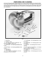
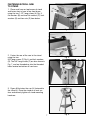
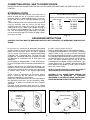
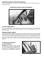
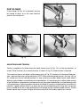
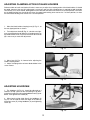
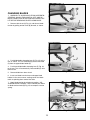
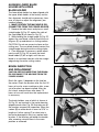
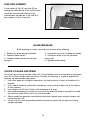
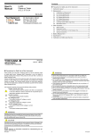
Quick
Quality
Quiet
DATED 11-25-98
1
PART NO. 1349463
© Delta International Machinery Corp. 1998
INSTRUCTION MANUAL
18" Variable Speed Scroll Saw
(Model 40-650, Type 2)
TABLE OF CONTENTS
SAFETY RULES..................................................................................................................................3
ADDITIONAL SAFETY RULES FOR SCROLL SAWS ........................................................................4
UNPACKING AND CLEANING ........................................................................................................5-6
ASSEMBLY INSTRUCTIONS..............................................................................................................6
Assembling Stand ..............................................................................................................................6
Fastening Scroll Saw To Stand ..........................................................................................................7
Assembling Rear Leg Height Extension ............................................................................................8
Assembling Holddown Foot ..............................................................................................................8
Rotating Table To 90 Degree Position ................................................................................................8
Assembling Table Insert ....................................................................................................................8
CONNECTING SCROLL SAW TO POWER SOURCE ........................................................................9
Extension Cords ................................................................................................................................9
Grounding Instructions ......................................................................................................................9
FASTENING STAND TO SUPPORTING SURFACE ..........................................................................10
OPERATING CONTROLS AND ADJUSTMENTS
On-Off Power Switch........................................................................................................................10
Variable Speed Control ....................................................................................................................10
Locking On-Off Switch In The “OFF” Position ................................................................................10
Dust Blower ......................................................................................................................................11
Adjusting Blade Tension ..................................................................................................................11
Adjusting Clamping Action Of Blade Holders ..................................................................................12
Adjusting Holddown ........................................................................................................................12
Changing Blades ..............................................................................................................................13
Tilting The Table................................................................................................................................14
Adjusting 90 And 45 Degree Positive Stops For Table ....................................................................14
Aligning Lower Blade Holder With Upper Blade Holder ..................................................................15
Brush Inspection And Replacement ................................................................................................15
Fuse Replacement............................................................................................................................16
BLADE BREAKAGE ..........................................................................................................................16
CHOICE OF BLADE AND SPEED ....................................................................................................16
2
3
ADDITIONAL SAFETY RULES
FOR SCROLL SAWS
1. WARNING: Do not operate your scroll saw until it is
completely assembled and installed according to the
instructions.
2. IF YOU ARE NOT thoroughly familiar with the operation of Scroll Saws, obtain advice from your supervisor, instructor or other qualified person.
3. YOUR SCROLL SAW STAND MUST be fastened to
the floor if there is any tendency for the stand to move
during operation.
4. THIS SCROLL SAW is intended for indoor use only.
5. MAKE SURE blade is properly tensioned before
operating saw.
Only feed the material fast enough so that the blade will
cut.
20. NEVER start the Scroll Saw with the stock pressed
against the blade.
21. WHEN cutting a large workpiece MAKE SURE the
material is supported at table height.
22. USE CAUTION when cutting material which is
irregular in cross section which could pinch the blade
before the cut is completed. A piece of moulding for
example must lay flat on the table and not be permitted to rock while being cut.
6. TO AVOID blade breakage ALWAYS adjust blade
tension correctly.
23. USE CAUTION when cutting round material such as
dowel rods or tubing. They have a tendency to roll
while being cut causing the blade to “bite.” Use a Vblock to control the piece.
7. MAKE SURE the blade teeth point downward
toward the table.
24. ALWAYS release blade tension before loosening the
blade holder.
8. NEVER turn the saw “ON” before clearing the table
of all objects (tools, scraps of wood, etc.).
25. MAKE CERTAIN table tilting lock is tightened before
starting the machine.
9. DO NOT cut material that is too small to be safely
supported.
26. NEVER reach under the table while the machine is
running.
10. AVOID awkward hand positions where a sudden
slip could cause a hand to move into the blade.
27. NEVER perform layout, assembly or set-up work on
the table while the saw is operating.
11. ALWAYS keep hands and fingers away from blade.
28. ALWAYS STOP the saw before removing scrap
pieces from the table.
12. ALWAYS adjust holddown foot for each new
operation.
13. DO NOT USE dull or bent blades.
14. DO NOT attempt to saw material that does not
have a flat surface, unless a suitable support is used.
15. MAKE “relief” cuts before cutting long curves.
16. NEVER attempt to cut a curve that is too tight for
the blade being used.
17. WHEN backing a blade out of a workpiece, the
blade may bind in the saw kerf. This is usually caused
by sawdust in the kerf. If this happens, turn “OFF” the
switch and remove plug from power source outlet.
Wedge open the kerf and back blade out of the workpiece.
18. ALWAYS hold the work firmly against the table.
19. DO NOT feed the material too fast while cutting.
4
29. SHOULD any part of your Scroll Saw be missing,
damaged or fail in any way, or any electrical component
fail to perform properly, shut off switch and remove
plug from power supply outlet. Replace missing, damaged or failed parts before resuming operation.
30. ADDITIONAL INFORMATION regarding the safe and
proper operation of this product is available from the
National Safety Council, 1121 Spring Lake Drive, Itasca,
IL 60143-3201, in the Accident Prevention Manual for
Industrial Operations and also in the Safety Data Sheets
provided by the NSC. Please also refer to the American
National Standards Institute ANSI 01.1 Safety Requirements for Woodworking Machinery and the U.S. Department of Labor OSHA 1910.213 Regulations.
31. SAVE THESE INSTRUCTIONS. Refer to them frequently and use them to instruct other users.
UNPACKING AND CLEANING
Your new scroll saw and stand is shipped complete in one container. Carefully unpack the saw, stand and all loose
items from the shipping container. Figure 2 illustrates the saw and all loose items and Figure 3 illustrates the stand
and all related parts. Remove the protective coating from the saw table surface. This coating may be removed with a
soft cloth moistened with kerosene (do not use acetone, gasoline or lacquer thinner for this purpose). After cleaning,
cover the table surface with a good quality paste wax. Buff out the wax thoroughly to prevent it from rubbing into
your workpieces.
14
11
1
13
12
10
9
18
5
2
3
7
6
4
Fig. 2
9 - Flat Washers - for fastening front of saw
to stand (4)
10 - Lockwashers - for fastening front of saw
to stand (2)
11 - Hex Nuts - for fastening front of saw to
stand (2)
12 - 5/8" Long Hex Head Screws - for fastening rear of saw to stand (2)
13 - Lockwashers - for fastening rear of saw
to stand (2)
14 - Flat washers - for fastening rear of saw to
stand (2)
1 - Scroll Saw
2 - Holddown Foot
3 - 1/2" Long Hex Socket Head Screw - for
fastening holddown foot to rod
4 - Lockwasher - for fastening holddown foot
to rod
5 - Flat Washer - for fastening holddown foot
to rod
6 - Table Insert
7 - 5mm Wrench
8 - 1-1/2" Long Hex Head Screws - for fastening front of saw to stand (2)
5
16
15
17
18
19
22
20
21
23
Fig. 3
15
16
17
18
19
-
Bottom Shelf
Legs (3)
Left Top Brace
Right Top Brace
Front Top Brace
20
21
22
23
-
Height Adjustment Bracket for rear leg
Flat Washers (28)
5/8" long (8mm) Carriage Bolts (28)
Hex Nuts (28)
ASSEMBLY INSTRUCTIONS
WARNING: FOR YOUR OWN SAFETY, DO NOT CONNECT THE SCROLL SAW TO THE POWER
SOURCE UNTIL THE MACHINE IS COMPLETELY ASSEMBLED AND YOU HAVE READ AND
UNDERSTOOD THE ENTIRE OWNERS MANUAL.
ASSEMBLING STAND
A
1. Assemble the stand, as shown in Fig. 4,
using the 24 carriage bolts, flat washers and
hex nuts. NOTE: The round holes on the top
of the two top braces (A) are to be positioned
toward the rear leg (B) and all three legs are
positioned outside the bottom shelf and top
braces. DO NOT TIGHTEN STAND MOUNTING HARDWARE AT THIS TIME.
B
A
6
Fig. 4
FASTENING SCROLL SAW
TO STAND
A
1. Place scroll saw on top braces of stand
and fasten front of saw to top front brace
using the two 1-1/2" long screws (A) Fig. 5,
flat washers (B) and two flat washers (C), lock
washers (D) and hex nuts (E) from below.
C
B
D E
A
B
Fig. 5
G
F
2. Fasten the rear of the saw to the stand
using the two
5/8" long screws (F) Fig. 6, and lock washers
(G). The 5/8" long screws (F) are also shown in
Fig. 7, and are threaded up into the threaded
holes located on bottom of saw base.
Fig. 6
F
F
Fig. 7
3. Figure 8 illustrates the saw (H) fastened to
the stand (J). Place the stand on a level surface and securely tighten all stand mounting
hardware.
H
J
7
Fig. 8
ASSEMBLING REAR LEG
HEIGHT EXTENSION
1. A height extension (A) Fig. 9, is supplied
with your stand and can be assembled to the
rear leg of the stand, as shown, using the four
carriage bolts (B), flat washers and nuts supplied. The height extension enables you to tilt
the saw forward during operation if desired.
Five holes are supplied in the extension (A) to
vary the degree of tilt.
B
A
ASSEMBLING
HOLDDOWN FOOT
1. With wrench supplied, assemble holddown
foot (A) Fig. 10, to rod (B) using 1/2² hex socket head screw (C)
with lockwasher and flat washer. Prongs of
holddown foot (A) should straddle blade.
2. Adjustment to holddown rod (B) Fig. 10,
can be made by loosening lock handle (D) and
raising or lowering rod (B). Tighten lock handle
(D). NOTE: Lock handle (D) Fig.10, is springloaded and can be repositioned by pulling
outward on the handle and repositioning it on
the stud located underneath the hub of handle
(D).
Fig. 9
A
D
C
B
Fig. 10
ROTATING TABLE TO
90 DEGREE POSITION
1. The saw is shipped with the table tilted 45
degrees to the right, as shown in Fig. 11. To
move the table to the 90 degree position,
loosen lock handle (A) and rotate table all the
way to the left. Then tighten lock handle (A).
NOTE: Lock handle (A) is spring-loaded and
can be repositioned by pulling out the handle
and repositioning it on the stud located underneath the hub of the handle.
A
Fig. 11
B
2. Fig. 12 illustrates the table (B) in the 90
degree position.
ASSEMBLING TABLE INSERT
C
1. Assemble the table insert (C) Fig. 12, to
opening in the center of the table (B) as
shown.
8
Fig. 12
CONNECTING SCROLL SAW TO POWER SOURCE
IMPORTANT: BEFORE CONNECTING THE SAW TO THE POWER LINE, MAKE SURE THE SWITCH IS IN THE “OFF”
POSITION.
EXTENSION CORDS
EXTENSION CORD SIZE
The use of any extension cord will cause some loss of
power. To keep this loss to a minimum, make sure the
extension cord is in good condition and is a 3-wire extension cord which has a 3-prong grounding type plug
and
a
3-pole receptacle which will accept the tool’s plug. When
using an extension cord, be sure to use one heavy
enough to carry the current of the scroll saw. An undersized cord will cause a drop in line voltage resulting in
loss of power and overheating. Fig. 13, shows the correct size to use depending on cord length. If in doubt,
use the next heavier gage. The smaller the gage number,
the heavier the cord.
LENGTH OF EXTENSION 120 VOLT WIRE SIZE REQUIRED
(AWG - American Wire Gage)
CORD IN FEET
0
26
51
101
-
25
50
100
150
18
16
16
14
AWG
AWG
AWG
AWG
Fig. 13
GROUNDING INSTRUCTIONS
CAUTION: THIS TOOL MUST BE GROUNDED WHILE IN USE TO PROTECT THE OPERATOR FROM ELECTRIC
SHOCK.
In the event of a malfunction or breakdown, grounding
provides a path of least resistance for electric current to
reduce the risk of electric shock. This tool is equipped
with an electric cord having an equipment-grounding
conductor and a grounding plug. The plug must be
plugged into a matching outlet that is properly installed
and grounded in accordance with all local codes and
ordinances.
Do not modify the plug provided - if it will not fit the outlet, have the proper outlet installed by a qualified electrician.
Improper connection of the equipment-grounding conductor can result in risk of electric shock. The conductor
with insulation having an outer surface that is green with
or without yellow stripes is the equipment-grounding
c
o
n
ductor. If repair or replacement of the electric cord or
plug is necessary, do not connect the equipment
grounding conductor to a live terminal.
Check with a qualified electrician or service personnel if
the grounding instructions are not completely understood, or if in doubt as to whether the tool is properly
grounded.
Use only 3-wire extension cords that have 3-prong
grounding type plugs and 3-hole receptacles that accept
the tool's plug, as shown in Fig. 14.
Repair or replace damaged or worn cord immediately.
If a properly grounded outlet is not available, a temporary
adapter, shown in Fig. 15, may be used for connecting
the 3-prong grounding type plug to a 2-prong receptacle.
The temporary adapter should be used only until a properly grounded outlet can be installed by a qualified electrician. The green colored rigid ear, lug, or the like
extending from the adapter must be connected to a permanent ground such as a properly grounded outlet box
cover. Whenever the adapter is used, it must be held in
place with a metal screw.
NOTE: In Canada, the use of a temporary adapter is
not permitted by the Canadian Electric Code.
CAUTION: IN ALL CASES, MAKE CERTAIN THE
RECEPTACLE IN QUESTION IS PROPERLY
GROUNDED. IF YOU ARE NOT SURE, HAVE A CERTIFIED ELECTRICIAN CHECK THE RECEPTACLE.
GROUNDED OUTLET BOX
GROUNDED OUTLET BOX
CURRENT
CARRYING
PRONGS
GROUNDING MEANS
ADAPTER
GROUNDING BLADE IS
LONGEST OF THE 3 BLADES
Fig. 14
Fig. 15
9
FASTENING STAND TO SUPPORTING SURFACE
If there is any tendency for the scroll saw to move during operation, the scroll saw stand must be
fastened to the floor.
OPERATING CONTROLS AND ADJUSTMENTS
C
A
B
Fig. 16
ON-OFF POWER SWITCH
The on-off switch (A) Fig. 16, is located on the top of the arm, as shown. To turn the saw “ON” push
down on the “ON” portion of the switch and to turn the saw “OFF” push down on the “OFF” portion of the switch.
VARIABLE SPEED CONTROL
Your scroll saw can be operated at speeds of 300 to 2000 cutting strokes per minute by rotating
control knob (B) Fig. 16. With the control knob (B) rotated all the way toward the front of the
machine the speed will be 300 cutting strokes per minute and with the control knob (B) rotated all
the way to the rear, the speed will be 2000 cutting strokes per minute. A series of numbers are provided on the control knob, as shown, and a witness line (C) is provided on the arm to be used for
reference.
LOCKING ON-OFF SWITCH
IN “OFF” POSITION
A
IMPORTANT: We suggest that when the scroll
saw is not in use, the on-off switch be locked in
the “OFF” position using a padlock (A), as
shown in Fig. 17. Available as an accessory
from Delta is the 50-325 padlock, shown at (A).
Fig. 17
10
DUST BLOWER
A dust blower (A) Fig. 18, is provided, and can
be moved to direct air to the most effective
point on the cutting line.
A
Fig. 18
A
A
Fig. 19
Fig. 20
ADJUSTING BLADE TENSION
Tension is applied to the blade when the blade tension lever (A) Fig. 19, is in the rear position, as
shown. When the lever (A) is moved forward, as shown in Fig. 20, blade tension is released.
To increase tension on the blade, rotate tension lever (A) Fig. 20, clockwise; to decrease blade tension, rotate tension lever counterclockwise. NOTE: When adjusting blade tension, the lever (A) Fig.
20, should be in the full forward position.It is only necessary to adjust blade tension knob when a
different type of blade is assembled to the blade holders. It is not necessary to adjust blade tension
when the blade is removed from and replaced in only the upper blade holder, as in performing inside
cutting operations. Adjusting proper tension on the blade is usually accomplished by trial and error;
however, a good method to use is to pluck the rear of the blade like guitar string after the tension
lever is moved to the rear. A high-pitched tone of the blade usually indicates proper tension. Thicker
blades require more tension (a higher pitched sound) while finer blades require less tension.
11
ADJUSTING CLAMPING ACTION OF BLADE HOLDERS
Different widths of scroll saw blades will make it necessary to adjust the clamping action of the blade holders. It should
be noted, however, that very little adjustment is necessary and very little clamping force is required to hold the blade
satisfactorily. As a rule of thumb, looking down at the table with the table insert slot in the 6 o’clock position, resistance
on the blade locking lever should be felt when the upper blade locking lever reaches the 7 o’clock position, or when
the lower blade locking lever reaches the 5 o’clock position.
1. Move the blade holder clamping lever (A) Fig. 21, to
the rear (open) position as shown.
2. Turn adjustment knob (B) Fig. 21, clockwise to tighten or counterclockwise to loosen the clamping action on
the blade holder. NOTE: Very little movement of the knob
(B) is necessary to make the adjustment.
Fig. 21
3. Move lever (A) Fig. 22, forward after adjusting the
blade clamping action.
4. Adjust clamping action on lower blade holder in the
same manner.
A
Fig. 22
ADJUSTING HOLDDOWN
1. The holddown (A) Fig. 23, should be adjusted so it
contacts the top surface of the work being cut by loosening lock handle (B) and moving holddown rod (C) up or
down. Then tighten lock handle (B).
C
A
B
2. When bevel cutting (table tilted), the holddown (A)
Fig. 23, can be tilted to match the angle of the table by
loosening screw (D), tilting holddown (A) and tightening
screw (D).
D
Fig. 23
12
CHANGING BLADES
B
1. WARNING: TO AVOID INJURY FROM ACCIDENTAL
STARTING, ALWAYS TURN SWITCH “OFF” AND REMOVE POWER CORD PLUG FROM ELECTRICAL OUTLET BEFORE REMOVING OR REPLACING BLADE.
A
2. Remove table insert (A) Fig. 24, and release blade
tension by pulling tension lever (B) forward, as shown.
Fig. 24
B
E
D
3. Push blade holder clamping lever (C) Fig. 25, to the
rear as shown. This will automatically release the blade
(D) from the upper blade holder (E).
C
4. Push lower blade holder clamping lever (F) Fig. 26,
to the rear. This will automatically release blade (D) from
lower chuck.
Fig. 25
5. Remove blade from lower chuck.
6. Insert new blade into the lower and upper blade
holders in the same manner, making certain the blade
teeth are pointing down toward the table.
7. Apply blade tension by referring to section, “ADJUSTING BLADE TENSION.” NOTE: NEVER push down
on blade tension knob (B) Fig. 25, to compress tension
spring.
D
F
Fig. 26
13
TILTING THE TABLE
1. The table on your scroll saw can be tilted up to 45
degrees to the right for bevel cutting operations by loosening table lock handle (A) Fig. 27. Tilt the table to the
desired angle and tighten lock handle (A). A scale and
pointer (B) Fig. 27, is provided to determine the angle of
tilt.
2. The table can also be tilted up to 15 degrees to the
left for bevel cutting operations by lowering the stop
block (C) Fig. 27, and tilting the table to the desired
angle, as shown in Fig. 28. Tighten lock handle (A).
C
A
B
Fig. 27
ADJUSTING 90 AND 45
DEGREE POSITIVE STOPS
FOR TABLE
1. Loosen table lock handle and move the table all the
way to the left and tighten table lock handle.
2. Using a square (A) Fig. 29, check to see if the table
is 90 degrees to the saw blade, as shown.
3. If the table is not at 90 degrees to the blade, adjust
the table accordingly, making certain screw (B) Fig. 30,
contacts bottom of table surface when table is 90
degrees to the blade. Screw (B) can be adjusted by
loosening nut (C), thread screw (B) in or out the desired
distance and tighten nut (C).
C
Fig. 28
4. Tilt table all the way to the right, as shown in Fig.
31,
and tighten table lock handle.
5. Using a square (D) Fig. 31, check to see if the table
is 45 degrees to the saw blade, as shown.
A
6. If the table is not at 45 degrees to the blade, adjust
the table accordingly, making certain screw (E) Fig. 30,
contacts side of base when the table is at 45 degrees
to the blade.
Fig. 29
D
B
E
C
Fig. 30
14
Fig. 31
ALIGNING LOWER BLADE
HOLDER WITH UPPER
BLADE HOLDER
E
The lower blade holder has been aligned with
the upper blade holder at the factory and further alignment should not be necessary; however, to check or adjust the alignment, proceed as follows:
1. MAKE CERTAIN THE MACHINE IS DISCONNECTED FROM THE POWER SOURCE.
2. Remove the table insert and place a small
straight edge (A) Fig. 32, against the side of
the saw blade (B) as shown in Fig. 32.
3. While holding the straight edge (A) Fig. 32,
against the saw blade, carefully move the cutting arm (E) up and down in a cutting motion.
CAUTION: Do not use excessive force on the
cutting arm. The saw blade should contact the
straight edge during the entire cutting stroke.
4. If an alignment is necessary, rotate adjustment screw (C) Fig. 33, to move the lower
blade holder (D) left or right, until the saw
blade is in consistent contact with the straight
edge during the entire cutting stroke.
B
A
Fig. 32
D
C
Fig. 33
BRUSH INSPECTION
AND REPLACEMENT
A
CAUTION: BEFORE INSPECTING THE BRUSHES, DISCONNECT THE MACHINE FROM THE
POWER SOURCE.
Brush life varies. It depends on the load on
the motor. Check the brushes after the first 50
hours of use for a new machine or after a new
set of brushes has been installed. After the
first check, examine them after about 10
hours of use until such time that replacement
is necessary.
Fig. 34
B
The brush holders, one of which is shown at
(A) Fig. 34, are located i-n the motor housing
opposite each other. Fig. 35 illustrates one of
the brushes removed for inspection. When the
carbon (B) on either brush is worn to 3/16" in
length or if either spring (C) or shunt wire is
burned or damaged in any way, replace both
brushes. If the brushes are found serviceable
after removing, reinstall them in the same
position as removed.
C
15
Fig. 35
FUSE REPLACEMENT
A fuse holder (A) Fig. 36, and fuse (B) are
located up under the rear of the machine and
should be removed and checked if the
machine does not operate. If the fuse (B) is
bad, replace it with a 4 amp fuse.
B
A
Fig. 36
BLADE BREAKAGE
Blade breakage is usually caused by one or more of the following:
1. Bending the blade during installation.
2. Improper blade tension.
3. Improper blade selection for the work
being cut.
4. Forcing the work into the blade too rapidly.
5. Cutting too sharp a turn for the blade
being used.
6. Improper blade speed.
CHOICE OF BLADE AND SPEED
Your scroll saw will accept a wide variety of 5" flat end blades and can be operated at any speed
from 300 to 2000 cutting strokes per minute. Consider the following as a general guideline for
selecting a blade and operating speed.
1. Use a finer blade for cutting thin workpieces, for hard materials, or when a smoother cut is
required.
2. Use a coarser blade for cutting thick workpieces, when making straight cuts or for medium
to soft materials.
3. Use a blade that will have 2 teeth in the workpiece at all times.
4. Most blade packaging is marked with the size of the wood the blade is intended to cut and
the minimum radius which can be cut with that blade.
5. Slower speeds are generally more effective than faster speeds when using thin blades and
making intricate cuts.
6. Always start at a slow speed and gradually increase the speed until the optimum cutting
speed is obtained.
16