1
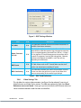
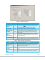
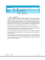
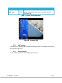
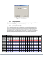
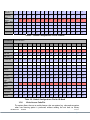
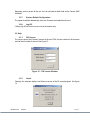
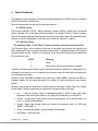
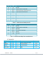
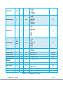
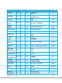
Software Manual The most important thing we build is trust. VETA Receiver Series 100-M0131X1A 02/10/10 Cobham Surveillance GMS Products 1916 Palomar Oaks Way Ste 100 Carlsbad, CA 92008 T: 760-496-0055 F: 760-496-0057 www.cobham.com/gms Table of Contents 1. Acronyms .................................................................................................................................................................... 5 2. Software Control Overview ............................................................................................................................ 7 2.1 System Requirements............................................................................................................................................... 7 2.2 Software Installation................................................................................................................................................. 7 2.3 Product Control & Status Monitoring Approach ......................................................................................... 8 2.4 VETA RX Configurator Functions ........................................................................................................................ 8 2.5 Access levels ................................................................................................................................................................. 9 2.6 Main Page Tab.............................................................................................................................................................. 9 2.6.1 The RF Parameters Group .............................................................................................................................. 9 2.6.2 Link Status Group ............................................................................................................................................ 10 2.6.3 Configuration Group ..................................................................................................................................... 11 2.6.4 Status Indicators ............................................................................................................................................. 12 2.6.5 BDC Set Up Button ........................................................................................................................................ 12 2.6.6 Video Settings Tab ......................................................................................................................................... 13 2.6.7 Security Tab ...................................................................................................................................................... 15 2.6.8 User Data Tab ................................................................................................................................................... 17 3. Pull-Down Menu Definitions ...................................................................................................................... 18 3.1 File................................................................................................................................................................................... 18 3.2 Options ......................................................................................................................................................................... 18 3.2.1 Special Setup .................................................................................................................................................... 19 3.2.2 BDC Settings ..................................................................................................................................................... 20 3.2.3 Polling Options ................................................................................................................................................. 20 3.2.4 Administrator Login ....................................................................................................................................... 21 3.2.5 Load Configuration File ............................................................................................................................... 21 3.2.6 Write License Code/File ............................................................................................................................... 22 3.2.7 Restore Default Configuration ................................................................................................................. 23 3.2.8 Log Off ................................................................................................................................................................. 23 3.3 Help ................................................................................................................................................................................ 23 3.3.1 FW Version ........................................................................................................................................................ 23 3.3.2 About .................................................................................................................................................................... 23 4. Control Protocols ............................................................................................................................................... 25 4.1 4.2 4.3 RS232 Control ........................................................................................................................................................... 25 Packet Structure ....................................................................................................................................................... 25 Command List ........................................................................................................................................................... 26 100-M0131X1A 02/10/10 2 of 31 www.cobham.com/gms List of Figures Figure 1 – VETA RX Configurator.......................................................................................................................................... 8 Figure 2 – VETA RX GUI Main Screen................................................................................................................................. 9 Figure 3 – BDC Settings Window ....................................................................................................................................... 13 Figure 4 – Video Settings Tab ............................................................................................................................................. 14 Figure 5 – Security Tab ........................................................................................................................................................... 16 Figure 6 – Security Tab in B-crypt Mode ....................................................................................................................... 16 Figure 7 – User Data Tab ....................................................................................................................................................... 17 Figure 8 – Options ..................................................................................................................................................................... 19 Figure 9 – Special Setup ......................................................................................................................................................... 19 Figure 10 – Standard OSD ..................................................................................................................................................... 20 Figure 11 – Polling Options ................................................................................................................................................... 21 Figure 12 – FW Version Window ....................................................................................................................................... 23 Figure 13 – About Box Window ......................................................................................................................................... 24 List of Tables Table 1 – RF Field Definitions .............................................................................................................................................. 10 Table 2 – Link Status Field Definitions ............................................................................................................................ 11 Table 3 – BDC Field Definitions .......................................................................................................................................... 13 Table 4– Video Selection Field Definitions ................................................................................................................... 14 Table 5 – Video Status ............................................................................................................................................................ 15 Table 6 – Encryption Field Definitions ............................................................................................................................ 17 Table 7 – User Data Field Definitions .............................................................................................................................. 18 Table 8 – Special Setup Parameters ................................................................................................................................. 20 Table 9 – Default Configurations File for LS-Band .................................................................................................... 22 Table 10 – Default Configurations File for CB-Band ................................................................................................ 22 Table 11 – Packet Structure Sending (from PC) ......................................................................................................... 26 Table 12 – Packet Structure Reply (from controlled device)................................................................................ 26 Table 13 – Commands for Tuners ..................................................................................................................................... 27 Table 14 – ‘g’ Commands ...................................................................................................................................................... 29 Table 15 – Decoder Configuration Commands .......................................................................................................... 29 Table 16 – Memory Configuration Commands .......................................................................................................... 30 Table 17 – Descrambling Commands .............................................................................................................................. 30 Table 18 – RS232 Data Pipe Commands ....................................................................................................................... 31 100-M0131X1A 02/10/10 3 of 31 www.cobham.com/gms Revision History Version Date X1 9-17-2009 Initial Release RM X1A 1-12-2010 Cobham branding DRF 100-M0131X1A 02/10/10 Main Changes from Previous version Edited by 4 of 31 www.cobham.com/gms 1. Acronyms This section lists and describes the various acronyms used in this document. Name 16QAM 16-state Quadrature Amplitude Modulation A/V Audio/Video AES Advanced Encryption System ABS Basic Encryption System (8 bit) C-OFDM Coded Orthogonal Frequency Division Multiplexing CSM Compact Surveillance Modem CVBS Composite Video BDC Block-Down Converter FEC Forward Error Correction GUI Graphical User Interface I/O Input/ Output KBaud Kilobaud per second Kbps Kilobits per second Mbps Megabits per second MER Modulation Error Rate MPEG Moving Picture Experts Group NTSC National Television System Committee PAL Phase Alternation Line QPSK Quadrature Phase Shift Keying QAM Quadrature Amplitude Modulation RF Radio Frequency RX Receiver S/N Signal-to-Noise Ratio THD Total Harmonic Distortion TX VDC 100-M0131X1A Meaning 02/10/10 Transmitter Volts (Direct Current) 5 of 31 www.cobham.com/gms 100-M0131X1A VDL VETA Digital Link VR VETA Receiver VT VETA Transmitter VDR VETA Digital Repeater VMT VETA Messenger Transmitter VNA VETA Network Adapter UDP User Datagram Protocol 02/10/10 6 of 31 www.cobham.com/gms 2. Software Control Overview This Software is used for all GMS products based on VETA Receivers, including VR, VMR, MVRD and MVMR. However each product uses specific control cable. Control cables, as well as connector pin outs, are described in details in corresponding product manual. Configuration, control and monitoring of the VETA Series Receivers are enabled through the use of GMS’ optional (sold separately) MS Windows-based VETA RX Configurator software program (GMS Part Number 630-SW0093*). This Graphical User Interface (GUI) program provides the end user with a straightforward way to interface with the VETA Receiver units (including VR, VMR, VDR RX, etc). During normal operation, once a VDL link is established, the VETA RX Configurator GUI can be used to monitor the link statistics as well as control the receiver. Monitoring the link statistics is an optional operation therefore, if desired, the VETA RX Configurator GUI does not need to be active and can be disconnected from the VETA RX unit after the link is established. 2.1 System Requirements The VETA RX Configurator program has been developed and tested on Windows 2000, Windows XP and Windows NT. Although the VETA RX Configurator program may work properly on other operating systems, no GMS support or assistance can be provided concerning other operating systems. 2.2 Software Installation The following instructions outline the installation process for the VETA RX Configurator program: Insert provided CD-ROM into computer. Click on ‘setup.exe’ file. This will launch the GMS_VR Setup program and several initial setup files will begin to be copied onto the computer. After the initial setup files are copied over, the GMS_VR Setup program will prompt the user to close any applications that are running. Once all other programs are exited, click on the ‘OK’ button. The GMS_VR Setup program will prompt the user to click on the ‘computer icon’ button to begin installation. If desired, the user can change the destination directory from the default. Click on the ‘computer icon’ button. The GMS_VR Setup program will then prompt the user to ‘Choose Program Group’. If desired, the user can change the program group from the default. Click on the ‘Continue’ button. After installing the VETA RX Configurator program, the GMS_VR Setup program will put up a window indicating that setup was completed successfully. Click ‘OK’. 100-M0131X1A 02/10/10 7 of 31 www.cobham.com/gms 2.3 Product Control & Status Monitoring Approach GMS Transmitters and Receivers provide programmable presets or configurations that can be set up through special programming software by Administrators. Configurations are selected by the user though M.S. Windows Application programs. The VETA products allow 16 configurations. Administrators define the configurations for specific applications. Each configuration completely defines all of the Unit parameters including center frequency, modulation parameters, Video, Audio, User data and encryption. Field personnel will select specific configuration via predetermined guidance from the Administrators. Matching the Transmitter operation to the Receiver operation is as simple as selecting the same configuration for both. For example: If the Transmitter is set to configuration #3, then the Receiver needs to be set to configuration #3 for them to operate together. 2.4 VETA RX Configurator Functions The VETA RX Configurator program provides the user access to many different configuration, control and monitoring options. When the VETA RX Configurator program is launched, the screen shown in Figure 1 is displayed. The user should first select the serial port their computer is connected to via the Serial Port Selector and Status region. If the selected serial port is valid, the gray-colored status box will show ‘Ready’. The Device Selector region allows the end user to choose to interface to a VETA RX (receiver) unit. To configure a VETA RX, select the ‘VR’ box in the Device Selector region. Once the ‘VR’ box is selected, the screen shown in Figure 2 is displayed. The VETA RX Configurator program contains function buttons and all the configurable settings available on a VETA Receiver Units. The following sections explain, in detail, the various options. Figure 1 – VETA RX Configurator 100-M0131X1A 02/10/10 8 of 31 www.cobham.com/gms Figure 2 – VETA RX GUI Main Screen 2.5 Access levels As was mentioned previously, VETA Control Software has 2 levels of access – User and Administrator. To have full access to the controls, it is necessary to enter password provided by GMS into the Administrator Login window, which is located under Options pull-down menu. The password can only be changed by the factory. User Level Access only allows changing the predefined configuration groups. 2.6 Main Page Tab The VETA Receiver Control Software consist of four tab indexes: Main Page, Video Settings, Security and User Data tabs (see Figure 2). It also has three pull-down menus consisting of the FILE, OPTIONS and HELP. Under the menus are pull down submenus and selections which are explained in detail later in this document. The Main Page tab consist of the RF Parameters group, the Link Status group, the Configuration Group and a shortcut button to the BDC (block down converter) Setup parameters. 2.6.1 The RF Parameters Group This group consists of the following fields as shown Table 1 below along with explanation of each. Keep in mind the column labeled “R/W”. Any field marked “R” indicates this is a “read’ only (a status indicator), it cannot be changed by the user. Any field marked “R/W” or Read/Write, indicates the value can be changed by the user. 100-M0131X1A 02/10/10 9 of 31 www.cobham.com/gms After changing any “R/W” field with a new value the user must click on the APPLY button for the change to take effect. Clicking on the CANCEL button (or Query button) will cancel the operation (previous values are restored). Field R/W Description R/W RF input frequency at BDC (block down converter) input. The receive frequency can be changed by entering the new desired frequency in this field. R/W This field displays the bandwidth of the received OFDM signal. It should be set to the same bandwidth of the transmitter selected from the following values: 6, 7 or 8 MHz or with optional narrow bands 1.25 or 2.5 MHz R/W User selects the guard interval which matches the transmitter. Guard interval sizes are selected from the following values 1/32, 1/16, 1/8 or ¼. When in narrow band (1.25 or 2.5 MHz) guard intervals are limited to either 1/16 or 1/8. FEC R This field displays the COFDM FEC (forward error correction) that is being demodulated at the receiver. FEC values are 1/2, 2/3, 3/4, 5/6. When in narrow band (1.25 or 2.5 MHz) FEC values are limited to 1/3 or 2/3. OFDM Mode R This field displays the COFDM constellation (QPSK, 16 QAM) that is being demodulated at the receiver. R/W This field displays whether OFDM signal is set to Normal or Inverted Spectrum. RF Freq (MHz) Bandwidth Guard Interval OFDM Polarity Table 1 – RF Field Definitions 2.6.2 Link Status Group This group consists of read only fields (status indicators) along with a “Polling Enabled” checkbox and an “Update Status” button. The indicators are for both receiver A and receiver B (diversity inputs). The fields are shown in Table 2 below with a description. Field Level SNR 100-M0131X1A 02/10/10 R/W Description R This field indicates the received signal level. Normal levels are around -15 to -90 dBm. Keep in mind signals greater than -15 dBm will overload the front end (BDC-s) and cause poor performance and signals less than -90 dBm may be too weak. The gain settings of the BDC-s will affect these readings R Input Signal-to-Noise Ratio. This read-only field conveys the SNR of the received signal as measured by the demodulator. Value expressed in dB. In QPSK: values greater than 13dB represent strong RF signals. In 16-QAM; values greater than 18dB represent strong RF signals 10 of 31 www.cobham.com/gms Field R/W Description R This read-only field conveys the BER (Bit Error Rate) of the received signal after Read-Solomon (Outer Code) Forward Error Correction (FEC) processing and before Viterbi (Inner Code) FEC processing in the receiver chain. Value expressed in 10-6. BER Post Viterbi R This read-only field conveys the BER (Bit Error Rate) of the received signal after performing all error correction techniques in the receiver chain. Value expressed in 10-6. Any numbers greater than 0 in this field indicate the presence of un-correctable errors in the received stream and may result in packet errors. Demod Lock Status R This read-only field indicates that the demodulator is locked onto incoming RF input signal. Values are locked or not locked. Packet Errors R Indication of the number of packet errors in the TS. Excessive packet errors will cause picture glitches and artifacts BER Pre Viterbi Table 2 – Link Status Field Definitions The above fields are only updated once when the control software is first initialized. They are not updated further unless the Polling Enabled check box is checked, in which case polling is turned ON continuously. Under the “Options” menu there is a menu called “Polling Options”. In this window the user can set the polling interval (in ms) Note: When making changes to Receiver OFDM parameters, polling should be disabled to prevent GUI interfering with User changes. If the Polling Enabled check box is not checked, an Update Status button appears; by pressing this button the link status parameters are updated (refreshed) each time the button is pressed. 2.6.3 Configuration Group The Configuration Group consists of a pull down box in which one of eight configurations can be selected along with a LOAD button. The VETA Receiver can store (in memory) 8 configurations. These are pre-configured before leaving the factory but can be changed by the user. These 8 configurations are also set to match the transmitter before leaving the factory. Warning: If a configuration group is changed, it may not match the transmitter configuration group and the digital link may no longer work. Keep in mind the receiver and transmitter configuration groups settings must match. What you should know about configuration groups: 100-M0131X1A 02/10/10 11 of 31 www.cobham.com/gms Any field which is an R/W (read/write) can be and is stored in a configuration group. A group is selected by choosing one of the 16 groups and then clicking on the LOAD button. This action loads all R/W fields (under any of the TABs or pull down menus, not just the MAIN PAGE TAB) with the stored values of that group. A group can be changed by editing an R/W field and then clicking on the APPLY button (“APPLY” also automatically saves). All R/W field values (under any of the TABS or pull down menus, not just the MAIN PAGE TAB) are stored to the current configuration group (the current selected group). For example, current group 1 is selected and the existing RF FREQ is set at 2300 MHz. User wants to change it to 2250 MHz. User changes RF FREQ field to 2250 and then clicks on the APPLY button. New frequency is automatically saved to the current group 1. 2.6.4 Status Indicators The Demod lock status indicates if the demodulators are successfully locked to the RF signal. The MPEG Decoder Lock Status is an indication that the Video Decoder is successfully locked to the incoming digital bit stream. Both indicators must be locked to decode the transport stream to display video. These indicators can be very helpful in troubleshooting. For example let’s say the demod lock status is locked and the OSD (on screen display) is reporting good SNR readings; however the MPEG Decoder lock status is not locked. This could be an indication that video at the transmitter end has problems (of course it could indicate other errors as well). Scrambling Status indicates that incoming signal is scrambled. 2.6.5 BDC Set Up Button This button on the main page tab is basically a shortcut to the BDC (block down converters) setup page. It also can be found under the pull down Options Menu\System Setup\BDC. See Table 3 for an explanation the fields. Keep in mind you must click on the APPLY button in order for new values to take effect. Warning: These values are pre-set at the factory for each configuration group. If the values are changed they can prevent the digital link from working. Ensure they are correct before changing. 100-M0131X1A 02/10/10 12 of 31 www.cobham.com/gms Figure 3 – BDC Settings Window Field LO (MHz) Down Converter LO side BDC Power BDC Gain Setting R/W Description R/W This field allows definition of the local oscillator FREQUENCY of the BDCs (block down converters). R/W This field allows definition of the local oscillator side. Values are either HIGH or LOW side injection. High side injection means the LO is at a higher frequency than the RF. So if ‘RF freq’ – ‘LO freq’ = IF freq, then the IF Freq will be negative or the spectrum will be inverted. The opposite is true for LOW side injection. Selection of these values depends on the BDC-s used. They will vary depending on manufacturer. R/W This field determines if DC power is supplied to the BDCs via the IF Cable. Values are On or OFF. Caution: Make sure that the IF cable is not shorted prior to enabling DC power. R/W This field allows different gain values to be entered for the BDCs. It does not affect the gain of the system. It only allows for a more accurate reading of the received signal strength. Table 3 – BDC Field Definitions 2.6.6 Video Settings Tab This tab allows for various video parameters (see Figure 4) to be selected. It consists of Video Selections and Video Status sections. The fields are explained in Table 4 and Error! Reference source not found.. Once again you must click on the APPLY button after new values have been selected in order for them to take effect. 100-M0131X1A 02/10/10 13 of 31 www.cobham.com/gms Figure 4 – Video Settings Tab Field R/W Description Power-up Video Format R/W This field allows user to select between PAL, NTSC or NTSC with a 7.5IRE pedestal. NOTE: The VMR will automatically switch to the video format that it is locked onto (PAL or NTSC). NTSC Format R/W This field has two choices NTSC and NTSC with pedestal R/W This field allows the user to select between a blue field video output (a YES value) or a freeze frame (a NO value) when no video is present. MPEG 4 deblocking filter R/W This field allows user to turn the filter ON or OFF. The receiver must have the 1.25 MHz BW option for this setting. (Only used in Narrow Band modes) On Screen Display R/W The OSD can be turned OFF, monitor channel A or monitor channel B. Polling functions may interfere with the OSD display. Blue Screen On No Video Table 4– Video Selection Field Definitions Field R/W Description Decoder Locked Status R This is a read-only indicator is letting the user know if video decoder is locked to the incoming video. This indicator is also contained on the main page tab. Receiving Line Standard R This read –only indicator shows the Video Standard of received signal. Received Video Type R Shows the standard of the incoming TS (MPEG-2 or MPEG-4) 100-M0131X1A 02/10/10 14 of 31 www.cobham.com/gms Field R/W Description TX Video Input Lock R Shows if incoming signal is locked on Video Video PID R Shows the Video PID of TS Audio PID R Shows the Audio PID of TS Table 5 – Video Status 2.6.7 Security Tab This tab allows administrator to enable or disable encryption, to choose type of encryption to be used and enter the encryption key; ABS (supplied with link) and optional AES or Bcrypt. AES and B-crypt have 4 sub selections: 128, 128+, 256 and 256+. 128 requires 32 hex symbols for the Key, while type 256 is more secure and requires 64 hex symbols. If the Receiver in simple 128 or 256 modes, then the incoming signal can be decoded if the keys are matched or the incoming signal is not encrypted. While the + modes allow decoding of incoming signal only if it is encrypted and the security keys in the TX and RX match. If encryption is turned Off, then the Security Key window is displayed as shown in Figure 5. Descrambling Mode pull-down list has all encryption modes, however if the unit doesn’t have corresponding license it will return value that is licensed in the unit. Security key field is different for different encryption modes. The modes that require 64 character key (AES, AES+, B-crypt, B-crypt+) have to two boxes for lower and upper parts of the key. See Figure 6. User must enter the correct key, which must match the key of the transmitter. Clicking on the OK button will notify user if incorrect number of characters have been entered and user will not be able to exit this window unless the CANCEL button is clicked on or the right amount of characters are entered. 100-M0131X1A 02/10/10 15 of 31 www.cobham.com/gms Figure 5 – Security Tab Figure 6 – Security Tab in B-crypt Mode 100-M0131X1A 02/10/10 16 of 31 www.cobham.com/gms Field R/W Description Encryption R/W This field allows user to select between OFF, ABS, AES 128, AES 128+, AES 256 or AES 256+. (AES 128 and 256 are optional). Key R/W This field allows user to enter the proper number of characters for the encryption key. Table 6 – Encryption Field Definitions 2.6.8 User Data Tab This tab (see Figure 7) allows user to turn USER DATA ON or OFF. If turned ON, the receiver extracts any User Data component that may be in the transmitted stream. The data is presented on the DATA output port of the receiver on pins 8 & 9 of the J2 connector (see corresponding manual 100-M0087*). The DATA BAUD RATE field is a read only and basically just reports the transmitted RS232 data baud rate. Figure 7 – User Data Tab 100-M0131X1A 02/10/10 17 of 31 www.cobham.com/gms Field R/W User Data Description R/W This field allows user to select between ON & OFF values. When the control is set to ON, the user can extract RS232 data from the data output port (J2 pins 8 & 9) of the receiver. R This is a read only field that reports the baud rate of the RS232 data component that is present in the transport stream. Data Baud Rate Data Parity R/W User can choose from None, Even or Odd. Data PID R/W Shows the Data PID of TS Table 7 – User Data Field Definitions 3. Pull-Down Menu Definitions This section discusses the Pull-Down Menus that include FILE, OPTIONS and HELP. 3.1 File This menu contains only one selection - EXIT. The EXIT selection closes and exits the PC control software. Alternatively, the X box in the upper right hand corner of the window can be used to exit the program. 3.2 Options The number of selections in this menu depends on login level. For user level, this menu contains four selections: Special Setup BDC Settings Polling Options Administrator login Administrator login (see Figure 8) adds the following selections: Load Configuration File Write License Code Write License File Restore Default Configuration Log Off 100-M0131X1A 02/10/10 18 of 31 www.cobham.com/gms Figure 8 – Options 3.2.1 Special Setup Special Setup is configured at the factory for specific application and for advanced operations only. Consult GMS before changing any of these parameters. This selection brings up a window with special parameters (see Figure 9). Selections are described in Table 8. Figure 9 – Special Setup Field R/W Input Mode R/W This field allows the user select between RF input and Chaining Input. Chaining Output Source R/W The selections are Demod and Chaining In, determines the source for chaining output. ASI Output R/W Allows to select ASI Output before or after Descrambling Auto Spectrum Detection R/W When On the receiver automatically detects Spectrum Polarity. This selection is valid for Narrowband only. AGC Meter Scale R/W The range for this AGC scale is 0 – 10. Decimal point is allowed. 100-M0131X1A 02/10/10 Description 19 of 31 www.cobham.com/gms Field R/W R/W OSD Mode Description The selections are Standard OSD (see Figure 10 ), Alarm OSD Banner (displayed only when receiver is not decoding), Others (Advanced OSD). Table 8 – Special Setup Parameters Figure 10 – Standard OSD 3.2.2 BDC Settings Clicking on this selection opens up the BDC Settings window. This window was previously discussed in section 2.6.5. 3.2.3 Polling Options In this window the user can set the polling interval (in ms). 100-M0131X1A 02/10/10 20 of 31 www.cobham.com/gms Figure 11 – Polling Options 3.2.4 Administrator Login Administrator Login allows the user to access more selections by entering password that can be obtained from GMS. The password cannot be changed. 3.2.5 Load Configuration File This is a special feature that allows the Administrator to change all the parameters of the unit at once. GMS provides Configuration File that can be modified before loading into the unit. Examples of Default Configurations File for VR-s are shown in Table 9 and Table 10. After desired changes are made in the file, save and close it. Ensure that no any Excel file is open during loading. Click Load Configuration File and select file from desired location. PARAMETER CONFIGURATIONS Config # 1 2 3 4 5 6 7 8 9 10 11 12 13 14 15 16 Unit Mode DVBT DVBT DVBT DVBT DVBT DVBT DVBT DVBT DVBT DVBT DVBT DVBT DVBT NB NB NB BDC LO 2550 2550 2550 2550 2550 2550 2550 2550 2550 2550 2550 2550 2550 2550 2550 2550 BDC Side High High High High High High High High High High High High High High High High BDC Gain 0 0 0 0 0 0 0 0 0 0 0 0 0 0 0 0 COFDM BW 8Mhz 8Mhz 8Mhz 8Mhz 8Mhz 8Mhz 8Mhz 8Mhz 8Mhz 8Mhz 8Mhz 8Mhz 8Mhz 2.5Mhz 2.5Mhz 2.5Mhz RF Frequency 1755 1802 1850 1755 1802 1850 2200 2300 2400 2200 2300 2400 2345 1802 2300 1802 Modulation GI 1/4 1/4 1/4 1/8 1/8 1/8 1/8 1/8 1/8 1/32 1/32 1/32 1/4 1/16 1/16 1/16 OFDM Polarity Normal Normal Normal Normal Normal Normal Normal Normal Normal Normal Normal Normal Normal Invert Invert Invert NTSC Format NTSC NTSC NTSC NTSC NTSC NTSC NTSC NTSC NTSC NTSC NTSC NTSC NTSC NTSC NTSC NTSC 100-M0131X1A 02/10/10 21 of 31 www.cobham.com/gms Blue Screen on no Video MPEG4 deblocking Filter On screen Display Yes Yes Yes Yes Yes Yes Yes Yes Yes Yes Yes Yes Yes Yes Yes Yes No No No No No No No No No No No No No No No Yes OFF OFF OFF OFF OFF OFF OFF OFF OFF OFF OFF OFF OFF OFF OFF OFF OFF OFF OFF OFF OFF OFF OFF OFF OFF OFF OFF OFF OFF OFF OFF OFF Descrambling OFF OFF OFF OFF OFF OFF OFF OFF OFF OFF OFF OFF OFF OFF OFF OFF LNB Power ON ON ON ON ON ON ON ON ON ON ON ON ON ON ON ON Power up Video Format 525 525 525 525 525 525 525 525 525 525 525 525 525 525 525 525 Auto Detect Spect Table 9 – Default Configurations File for LS-Band PARAMETER CONFIGURATIONS Config # 1 2 3 4 5 6 7 8 9 10 11 12 13 14 15 16 Unit Mode DVB-T DVB-T DVB-T DVB-T DVB-T DVB-T DVB-T DVB-T DVB-T DVB-T DVB-T DVB-T DVB-T NB NB NB BDC LO 5200 5200 5200 5200 5200 5200 5200 5200 5200 5200 5200 5200 5200 5200 5200 5200 BDC Side High High High High High High High High High High High High High High High High BDC Gain 0 0 0 0 0 0 0 0 0 0 0 0 0 0 0 0 COFDM BW 8 MHz 8 MHz 8 MHz 8Mhz 8Mhz 8Mhz 8Mhz 8Mhz 8Mhz 8Mhz 8Mhz 8Mhz 7Mhz 2.5Mhz 2.5Mhz 2.5Mhz RF Frequency 4400 4700 5000 4400 4700 5000 4400 4700 5000 4400 4700 5000 4400 4700 5000 4400 Modulation GI 1/4 1/4 1/4 1/8 1/8 1/8 1/8 1/8 1/8 1/32 1/32 1/32 1/16 1/16 1/16 1/16 OFDM Polarity Normal Normal Normal Normal Normal Normal Normal Normal Normal Normal Normal Normal Normal Normal Normal Normal NTSC Format NTSC NTSC NTSC NTSC NTSC NTSC NTSC NTSC NTSC NTSC NTSC NTSC NTSC NTSC NTSC NTSC Yes Yes Yes Yes Yes Yes Yes Yes Yes Yes Yes Yes Yes Yes Yes Yes No No No No No No No No No No No No No No No Yes OFF OFF OFF OFF OFF OFF OFF OFF OFF OFF OFF OFF OFF OFF OFF OFF OFF OFF OFF OFF OFF OFF OFF OFF OFF OFF OFF OFF OFF OFF OFF OFF Descrambling OFF OFF OFF OFF OFF OFF OFF OFF OFF OFF OFF OFF OFF OFF OFF OFF LNB Power ON ON ON ON ON ON ON ON ON ON ON ON ON ON ON ON Pwr up Video Format 525 525 525 525 525 525 525 525 525 525 525 525 525 525 525 525 Blue Screen on no Video MPEG4 deblocking Filter On screen Display Auto Detect Spect Table 10 – Default Configurations File for CB-Band 3.2.6 Write License Code/File This option allows the user to enable features that are optional, e.g. advanced encryption, when new licensing option is purchased, without sending the unit back to factory. 100-M0131X1A 02/10/10 22 of 31 www.cobham.com/gms Depending on the version of the unit, the user will need to load Code or File. Contact GMS for details. 3.2.7 Restore Default Configuration This option should be selected only after new Firmware was loaded into the unit. 3.2.8 Log Off Clicking Log Off will restrict access to User Parameters only. 3.3 Help 3.3.1 FW Version This menu contains the Firmware Version of the unit, FPGA Version number of the firmware and the Serial number of the unit. See Figure 12. Figure 12 – FW Version Window 3.3.2 About Choosing this selection displays the Software version of the PC control program. See Figure 13. 100-M0131X1A 02/10/10 23 of 31 www.cobham.com/gms Figure 13 – About Box Window 100-M0131X1A 02/10/10 24 of 31 www.cobham.com/gms 4. Control Protocols The following section describes the control protocol employed on the RS232 link for controlling the VETA transmitters and Receivers. Refer to corresponding manuals for low level commands list. 4.1 RS232 Control The physical interface is RS232. Normal operation involves sending a packet from the control device (normally a PC) to the device being controlled. If the packet satisfies an address integrity check, then the controlled device will action the command and send a reply. For compatibility with modems an ASCII style protocol is used. Ports are set for 8 bits, No parity, 1 stop bit. 4.2 Packet Structure The following Table 11 and Table 12 show the packet structure send and receive. The Sum check byte is the summation of all bytes in the packet, not including the start and end bytes. Higher order bytes are ignored and the final byte result is modified to prevent ASCII control characters being sent. Bit 7 (highest) is forced high. Status byte will indicate command performed OK, or indicate an error. ASCII Meaning 1 All OK E General error, Command could not be actioned. Typically E will be returned if the message is formatted incorrectly (separators in wrong place) or if commands are in upper case, or if commands do not match against the allowed list of commands, or if the checksum is wrong. Addresses in the range 0001 to 9998 are for general use. Address 0000 is reserved and 9999 is a broadcast address. I.e. any device will reply to this address. Its reply will contain its own specific address. All data in the transmitter and receiver is stored as one of 5 data types: Double, String, List, Integer or Hex Integer. The data type dictates the contents of the data section of the reply. List – 1 byte for sending. Value is hexadecimal coded as ASCII. 2 byte reply. Reply represents index into original choice list. E.g. Reply 02 indicates entry 2 in original list. Double - variable length. Reply always contains decimal point and 4 decimal places, can have 1 to 3 digits before decimal. Integer - 6byte reply. Integer value with stuffed with preceding zeros. e.g. GOP reply 000012 = GOP length 12 String - Variable length. Reply is string excluding null terminator Hex Integer – 8byte Hex reply 100-M0131X1A 02/10/10 25 of 31 www.cobham.com/gms ASCII Value STX 02h 0-9 30h-39h 4 byte unit address. In range 0-9999 R 20h-7Eh 1 byte command type. r read, w write or m misc I 20h-7E 1 byte indicator of internal data block ABC 20h-7Eh Command –three byte mnemonic ; 3Bh PQR 20h-7Eh ; 3Bh Separator X 20h-7Eh Sum Check ETX 03h Start byte Separator Data –Optional, variable length End byte Table 11 – Packet Structure Sending (from PC) ASCII Value STX 02h 0-9 30h-39h 4 byte unit address. In range 0-9999 Z 20h-7Eh Status Byte PQR 20h-7E Data –Optional, variable length ; 20h-7Eh Separator X 3Bh Sum Check ETX 20h-7Eh Start byte End byte Table 12 – Packet Structure Reply (from controlled device) 4.3 Command List R/W Block Command Input Frequency R/W 1 ipf Frequency received by the antenna. Decimal point allowed Double BDC LO R/W 1 dco Decimal point allowed Double BDC LO Side R/W 1 los 0=Low 1=High Description 100-M0131X1A 02/10/10 Data Sent Data Type List 26 of 31 www.cobham.com/gms OFDM BW OFDM Mode OFDM FEC OFDM Guard R/W R R NB R/W DVBT R wid 0=8 MHz 1=7 MHz 2=6 MHz 3=2.5 MHz 4=1.25 MHz List mod NB Mode 0=QPSK 1=16QAM DVBT Mode 0=QPSK 1=16QAM 2=64 QAM List fec NB Mode 1=2/3 2=1/3 DVBT Mode 0=1/2 1=2/3 2=3/4 3=5/6 4=7/8 List 1 gua NB Mode 1=1/16 2=1/8 DVBT Mode 0=1/32 1=1/16 2=1/8 3= 1/4 List List 1 1 1 OFDM Polarity R 1 pol 0=Normal 1=Inverted Input SNR A R 1 snr Input SNR in dB Double Input SNR B R 1 mer Input SNR in dB Double BER Pre Viterbi R 1 pre Pre Viterbi x 10-6 Int BER Post Viterbi R 1 pos Post Viterbi x 10-6 Int Packet Errors R 1 pkt Errors Int Lock Status R 1 loc 0=Locked 1=Not Locked List Input Level A R 1 ina Input Level in dBm Double Input Level B R 1 inb Input Level in dBm Double Table 13 – Commands for Tuners 100-M0131X1A 02/10/10 27 of 31 www.cobham.com/gms R/W Block Command Unit Mode R/W g udm 0=Narrow Band 1=DVBT List Input Mode R/W g mod 0=RF Input 1=Chaining Input List LNB Power R/W g lnb 0=OFF 1=ON List RS 232 Address R/W g add Unit Address 0000-9999 Integer Software version R g sof Software Version Number String FPGA Version R g fpg FPGA Version Number String Serial Number R g ser Serial Number Hex String License Code W g lco License number to enable certain features List On Screen Display R/W g osd 0=Off 1=Channel A 2=Channel B List Auxiliary Address R/W g aux Unit Address 0000-9999 Integer AGC Meter Scale R/W g agc Range 0 - 10.0 Decimal point allowed Double Daisy Chain RS232 Control R/W g cdc 0=OFF 1=ON List Auto Spectrum Detection (NB) R/W g asd 0=OFF 1=ON List Chaining Output Mode 1 R/W g cha 0=Demod 1=Chaining In List Chaining Output Mode 2 R/W g ch2 0=Pre descrambling 1=Post descrambling List R g lma Bit mask of licensed features Integer R/W g dcg Range -30.0 -+30.0.Decimal point allowed Double R g bty PCB Type String R/W g cfm 0=8 Configurations 1=16 Configurations Description License Mask BDC Gain Offset Board Type Number of configurations 100-M0131X1A 02/10/10 Data Sent Data Type List 28 of 31 www.cobham.com/gms Description OSD Type R/W Block Command R/W g osp Data Sent Data Type 0=Standard 1=Enhanced List Table 14 – ‘g’ Commands Description R/W Block Command Unit Number R/W e ser Index into list of programs Preferred unit Name R/W e def Preferred unit Name 525 Video Format R/W e 525 0=NTSC 1=NTSC no Ped List Locked R e loc 0=No 1=Yes List Line Standard R e lin 0=625 1=525 Integer Fail mode R/W e fai 0=Freeze 1=Blue List Power Up Line Standard R/W e pwr 0=625 1=525 List R e scr 0=Clear 1=Scrambled List MPEG-4 Deblocking Filter R/W e deb 0=Enable 1=Disable List Received Video Type R e vid 0=MPEG-2 1=MPEG-4 List TX Video Input Lock R e txv 0=Unlocked 1=Locked List Default Service Name match R e dsm 0=No Match 1=Match List Video PID R e vpi 13 bit PID Integer Audio PID R e api 13 bit PID Integer Data PID R e dpi 13 bit PID Integer R/W e fra 0=Received signal 1=Local/Internal Scrambling status Video Frame Lock mode Data Sent Data Type List String List Table 15 – Decoder Configuration Commands 100-M0131X1A 02/10/10 29 of 31 www.cobham.com/gms Command Data Sent Data Type Description R/W Block Store current configuration R/W d sto Config Address (1-16) Load Configuration into current R/W d loa Config Address (1-16) Restore default build R/W d def 0=No 1=Yes Read number of last configuration R d las Config Address Integer Integer List Integer Table 16 – Memory Configuration Commands Description R/W Block Command Data Sent Data Type R/W z des 0=Off 1=ABS 4=AES128 5=AES128+ 6=AES256 7=AES256+ 8=Bcrypt128 9=Bcrypt128+ 10=Bcrypt256 11=Bcrypt256+ ABS Scrambling Key W z ebs Basic scrambling Key 8 digit hex string Scrambling Key – lower 128 bits W z aes AES Scrambling Key – lower 128 bits 32 digit hex string Scrambling Key – upper 128 bits W z a25 AES Scrambling Key – upper 128 bits 32 digit hex string Descrambling List Table 17 – Descrambling Commands Description R/W Block Data On/OFF R/W t 100-M0131X1A 02/10/10 Command Data Sent dat 0=OFF 1=ON Data Type List 30 of 31 www.cobham.com/gms Description R/W Data Baudrate Data parity Block Command Data Sent R t bau 2=1200 Baud 3=2400 Baud 4=4800 Baud 5=9600 Baud 6=19200 Baud 7=38400 Baud 8=57600 Baud 9=115200 Baud R/W t par 0=None 1=Even 2=Odd Data Type Integer List Table 18 – RS232 Data Pipe Commands 100-M0131X1A 02/10/10 31 of 31 www.cobham.com/gms