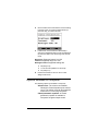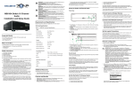
1
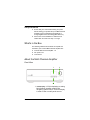
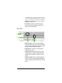
Disclaimer Control4® makes no representations or warranties with respect to this publication, and specifically disclaims any express or implied warranties of merchantability or fitness for any particular purpose. Control4 reserves the right to make changes to any and all parts of this publication at any time, without any obligation to notify any person or entity of such changes. Trademarks Control4, EZ ID, and the Control4 logo are trademarks or registered trademarks of Control4 Corporation. Other product and company names mentioned in this document may be the trademarks or registered trademarks of their respective owners. Copyright © 2009Control4. All rights reserved. Control4, the Control4 logo and Everyday Easy are registered trademarks or trademarks of Control4 Corporation in the United States and/or other countries. All other names or brands may be claimed as property by their respective owners. Pricing and specifications subject to change without notice. No part of this publication may be reproduced, photocopied, stored on a retrieval system, or transmitted without the express written consent of the publisher. Contact Us Control4 Corporation 11734 S. Election Road Salt Lake City, UT 84020 USA http://www.control4.com Multi Channel Amplifier - 16 Installation and User Guide Part Number: 200-00038 Rev C Hardware Model Number: C4-16AMP3-B 6/05/2009 Contents Preface Important Information .................................... 1 Graphical Symbols in this Guide............ 1 Graphical Symbols on the Device.......... 1 Safety Instructions ................................. 2 Additional Resources ............................. 3 Chapter 1 Introduction to Multi Channel Amplifier - 16... 5 Features and Benefits............................ 5 Requirements ........................................ 6 What’s in the Box ................................... 6 About the Multi Channel Amplifier ......... 6 Front View......................................... 6 Back View ......................................... 7 Chapter 2 Installing the Multi Channel Amplifier ............ 9 Plan Your Physical Layout ................... 10 Connect Audio Input Sources and Speakers.............................................. 11 Connect to the Network and Power ..... 12 Set Up Logical Connections ................ 12 Set Network Settings ........................... 13 Chapter 3 Using Multi Channel Amplifier ..................... 15 View Output Assignments.................... 15 Manage Amplifier Output Zones .......... 17 View or Change Output Settings .... 17 View or Change Input Settings ....... 19 View Network Settings ......................... 20 Set Display Preferences ...................... 20 Options Available in Composer ........... 21 Chapter 4 Regulatory Compliance ............................... 23 North America ...................................... 23 iii FCC Interference Statement........... 23 Industry Canada Statement ............ 23 Recycling Information ..................... 24 Warranty ......................................... 24 Index .....................................................................................25 iv PREFACE Important Information Graphical Symbols in this Guide Warning, Important, and Note paragraphs draw your attention to important safe practices and additional information which may help you avoid injury, death, or loss of material or time. WARNING! This indicates a potentially hazardous situation that, if not avoided, may result in death or serious injury. DO NOT IGNORE A WARNING! IMPORTANT! This indicates information that will help you avoid damage to your equipment, loss of materials, or loss of time. PAY ATTENTION TO THESE IMPORTANT STATEMENTS! NOTE: This indicates a note on related information about the current topic. Graphical Symbols on the Device The following information has been placed on the device: 1 Safety Instructions 1. Read these instructions. 2. Keep these instructions. 3. Heed all warnings. 4. Follow all instructions. 5. Do not use this apparatus near water. 6. Clean only with dry cloth. 7. Do not block any ventilation openings. Install in accordance with the manufacturer’s instructions. 8. Do not install near any heat sources such as radiators, heat registers, stoves, or other apparatus (including other amplifiers) that produce heat. 9. Do not defeat the safety purpose of the polarized or grounding-type plug. A grounding-type plug has two blades and a third grounding prong. The wide blade or the third prong are provided for your safety. If the provided plug does not fit into your outlet, consult an electrician for replacement of the obsolete outlet. 10. Protect the power cord from being walked on or pinched particularly at plugs, convenience receptacles, and the point where they exit from the apparatus. 11. Only use attachments/accessories specified by the manufacturer. 12. Use only with the cart, stand, tripod, bracket, or table specified by the manufacturer, or sold with the apparatus. When a cart is used, use caution when moving the cart/apparatus combination to avoid injury from tip-over. 13. Unplug this apparatus during lighting storms or when unused for long periods of time. 14. Refer all servicing to qualified service personnel. Servicing is required when the apparatus have been damaged in any way, such as power-supply cord or plug is damaged, liquid has been spilled or objects 2 have fallen into the apparatus, the apparatus has been exposed to rain or moisture, does not operate normally, or has been dropped. 15. Do not install in a cabinet that is smaller than 20” wide x 20” deep x 12” high. WARNING! Do not expose the apparatus to dripping or splashing. Do not place objects filled with liquids near the apparatus. WARNING! To reduce the risk of fire or electrical shock, do not expose this apparatus to rain or moisture. WARNING! Equipment must be connected to a Mains socket outlet with a protective earthing connection. WARNING! To reduce the risk of fire, do not install in a cabinet that is smaller than 20” wide x 20” deep x 12” high. If you do, the device may overheat. Additional Resources The following resources are available: Your Control4-authorized reseller Control4 Web Site: http://www.control4.com/ 3 4 CHAPTER 1 Introduction to Multi Channel Amplifier - 16 Control4 systems are uniquely configured for every customer and every site. A popular component among music lovers is the Control4 Multi Channel Amplifier. This chapter introduces the Control4 Multi Channel Amplifier - 16 and its features. Features and Benefits Receives up to eight stereo inputs with full audio switching on inputs. Outputs eight stereo class D amplified channels at 120 W per channel at 8 ohms or at 220 W per channel at 4 ohms (not all channels driven simultaneously). Adjustable gain, treble, and bass for each zone Master Volume Control for all outputs Control4 EZ ID™ LEDs for every I/O to make connections easy to identify Device chassis is three standard rack spaces and rack mountable using 4 standard rack spaces configuring to EIA 19” rack standards. The optional Control4 Rack Mount Kit (C4-4URMK-B) provides 1/2 U spacing above and below the chassis. If the Control4 Rack Mount Kit is not used, allow ½ rack space above and below the chassis for ventilation. Communicates via Ethernet 10/100 port and ZigBee mesh networking (IEEE 802.15.4). 5 Requirements Ensure that your home network wiring is in place before starting your system setup. The Multi Channel Amplifier can be controlled through Ethernet or through ZigBee mesh networking (IEEE 802.15.4). Device must not be installed in a cabinet that is smaller than 20” wide x 20” deep x 12” high. What’s in the Box The following hardware and software is required and included in your Control4 Multi Channel Amplifier box. Control4 Multi Channel Amplifier - 16 IEC power cord This manual About the Multi Channel Amplifier Front View 1 3 2 1. Front Display—LCD for displaying or setting Multi Channel Amplifier settings and navigating system menus. The front display is used to view or modify audio source 6 routing and zone settings for gain, bass, and treble. The display also shows zone activity. 2. Buttons—Provides access to menu options displayed on the LCD. 3. Select Dial—Rotate to scroll through list items and options displayed on the LCD. Press to make selections. Back View 1 2 3 4 1. Power Plug Port—For use with a standard IEC equipment power cord. Use the supplied power cord or ensure the power cord you are using is at least 18 AWG or larger. 2. Ethernet Port—RJ-45 for a 10/100 BaseT Ethernet connection 3. Audio Inputs 1-16—RCA jacks for 8 stereo analog sources, and their supporting light emitting diodes (LEDs) for EZ ID™ during setup 4. Amplifier Outputs 1-16—5-way binding post pair for 8 stereo class D amplified channels, and their supporting LEDs for EZ ID™ during setup 7 Technical Specifications Multi Channel Amplifier - 16 Table 1: Multi Channel Amplifier - 16 C4-16AMP3-B Multi Channel Amplifier - 16 Communications: Ethernet 10/100 base and Zigbee mesh networking Connections: 8 sets of stereo inputs 8 sets of amplifier outputs Dimensions: 5.25” x 17” x 16” Display: LCD screen Power requirements: 100-240 VAC, 50-60 Hz Shipping weight: approximately 28 lbs 8 CHAPTER 2 Installing the Multi Channel Amplifier This device operates as part of the Control4 home system, which requires physical connections and logical connections to function as designed. The essential setup tasks are: 1.Plan Your Physical Layout 2.Connect Audio Input Sources and Speakers 3.Connect to the Network and Power 4.Set Up Logical Connections 5.Set Network Settings This chapter describes, in general terms, how to set up the physical connections required for the Multi Channel Amplifier and all of the devices associated with it. To set up the logical connections required, refer to Control4 Composer User Guide software documentation. 9 Plan Your Physical Layout This section can help you plan your physical connections. Use a worksheet to plan your amplifier connections: Using the worksheet provided in Table 2-1 below, identify the connection you will use for all planned connections. 10 Output examples: Speakers 8 stereo channel outputs Amplifier Outputs— Input examples: CD changers, VCRs, TVs, DVD changers, or Media Controllers Audio Inputs— 8 stereo sources 1 A1B 2 A2B 3 A3B 4 A4B 5 A5B 6 A6B 7 A7B 8 A8B Table 2-1. Multi Channel Amplifier Connection Worksheet WARNING! Connecting speaker wires or input cables while the Multi Channel Amplifier is powered, may cause shock and could damage the amplifier. Connect Audio Input Sources and Speakers 1. Ensure the amplifier power cord is unplugged before connecting speakers and audio sources. 2. Connect up to eight stereo audio source devices to the RCA line level input jacks (the top row of connector on the back of your amp). Sources may include line level audio outputs from devices such as a Control4 Home Theatre Controller or Media Controller, tuners, CD or tape players, etc. Use the worksheet on the previous page to keep track of which source is connected to which amplifier input. 3. Connect speakers to the audio output jacks. Tighten the binding posts to ensure a good electrical connection to the speaker wires (even if you are using banana plugs, it is important to tighten the binding posts). Do not bridge outputs. The outputs on the C4-16AMP3 cannot be bridged. Do not connect black terminals together. Do not connect the black terminals to ground. The black terminals are not at ground potential and connecting them together or to ground can damage the amplifier. Use the work sheet on the previous page to keep track of which speaker zones are attached to which amplifier output channels. 11 Connect to the Network and Power 1. If you are using an Ethernet connection for the Multi Channel Amplifier, use a standard 10/100 Base T Ethernet cable to connect the Ethernet port on the amplifier to your network. NOTE: While the Multi Channel Amplifier can be controlled via either Zigbee or Ethernet networks, Control4 recommends that you use an Ethernet connection whenever possible as this will allow firmware upgrades to be performed on the product. The firmware on the amplifier cannot be upgraded over the Zigbee network. 2. Connect the power cord provided to the back of the Multi Channel Amplifier and to the power outlet. Once the power cord is connected, the Multi Channel Amplifier should power up. Set Up Logical Connections Physical and logical connections are required in order to control, navigate, and use the Multi Channel Amplifier as designed. Thus far you have set up the physical connections for the Control4 Multi Channel Amplifier. To complete the logical setup, use Control4 Composer Pro software (available to trained installers only) installed on a PC connected to the home network. For instructions, refer to the Control4 Composer Pro User Guide. 12 Set Network Settings 1. At the LCD screen, press the Network button. 2. On the Network Configuration screen, choose an Ethernet or ZigBee network by rotating and pressing the Select Dial. 3. If the amplifier is set to use a ZigBee network, the EUID, Gateway, and ZigBee channel number are displayed. The EUID and Gateway are static fields. The Zigbee channel number can be changed. Press the Select Dial to enter edit mode. Rotate the dial or use the Up or Down button to change the channel number. This screen has one menu option: Back: Returns to the Network Configuration screen. 4. If the switch is set to use an Ethernet network, the MAC, method of obtaining a network IP address, IP address, Mask, and GWay are displayed. The Audio Matrix Switch, by default, uses DHCP to obtain a network IP address. If the local area network does not support DHCP, you can configure the switch to use a Static IP address instead: 4a. Press the Select Dial to enter edit mode. 4b. Press the Down or Up button (or rotate the Select Dial) to choose Static IP. 13 4c. Press OK (or press the Select Dial). 4d. Press Save (or press the Select Dial). 4e. Edit the IP, Mask, and GWay fields for the Static IP network: Use the Select Dial to select a line, then press the dial. Use the Select Dial scroll the number up or down and edit as needed, then press the Select Dial to move to the next field within the number. 4f. When finished editing, press Save. 14 CHAPTER 3 Using Multi Channel Amplifier This chapter introduces the LCD user interface screens on the Multi Channel Amplifier and the common system tasks you can perform. Normal day-to-day tasks do not require manual control but instead are controlled using the Control4 user interface. View Output Assignments Once you complete the physical connections and logical connections (using the Composer software as needed), you can view or change your setup in the Multi Channel Amplifier front display. When you first power up the Multi Channel Amplifier, a System Status screen similar to the following one appears momentarily. The System Status screen is then replaced by the In to Out Assignments screen. The screen shows 8 output 15 zones and any assigned input sources (such as Input 1 as shown in the following screen). A shaded arrowhead indicates that a signal is present. The menu buttons on the front panel provide access to the following screen: Setup: Displays an output-specific screen, such as Output Zone 1. Network: Displays the Network Configuration screen. Display: Displays the Display Configuration Screen. NOTE: After leaving the Setup, Network, or Display menu and returning to the In to Out Assignments screen, you may need to wait for the screen to load before selecting another menu. 16 Manage Amplifier Output Zones View or Change Output Settings To view or change source settings: 1. On the In to Out Assignments screen, press the Setup button. The output settings of the default output screen (the last output screen accessed) are displayed. In the following example it is Output Zone 1. You can choose to view the settings for a different output screen by changing the output number (see Step 2). You can adjust the output settings by scrolling with the Select Dial, pressing the dial to edit, using the up or down button or the dial to change the setting, and pressing OK or the Select Dial to save changes. Input (number): If an input source is assigned, the Input source number is displayed (1 - 16). Gain (setting): Supported range: Mute INF 0 - 99 (-100 to 0 dB) NOTE: The gain setting cannot be larger than the volume limit. Limit: Set a volume limit. Options are 0 - 99 or off. Balance: Determine output balance. Options are Center, Left, Right, L-1 - L-19, or R-1 - R-19. 17 Menu buttons: Provide access to these screens: Inputs: Toggles view to a screen showing the gain for the currently assigned input. Tone: Displays the bass gain, bass frequency, treble gain, and treble frequency for this output. Exit: Returns to the In to Out Assignments screen. 2. (Conditional) View a different output number: If the output screen that you want to view is not displayed, use the Select Dial to select and change the output number at the top. 3. (Optional) Change an output setting: 3a. Using the Select Dial, highlight the Input, Gain, Limit, or Balance field and then press the Select Dial to enter Edit mode. 3b. Turn the Select Dial (or use the Up/Down buttons) to set a new number and then press the dial to save the setting. Input: 1-16 Gain: Mute, 0 - 99 (-100 to 0 dB) Limit: Off, 0-99 Balance: Center, Left, Right, L-1 - L-19, R1 - R-19 4. (Optional) Change a tone setting: 4a. From the Output screen, press the Tone button. Page 2 of the selected output screen is displayed. 4b. Rotate the Select Dial to highlight a tone setting. 18 Bass Gain: Supported range: -12 to +12 dB Bass Freq: Supported range: 40 to 315 Hz (in 1/3 octave increments) Treb Gain: Supported range: -12 to +12 dB Treb Freq: Supported range: 2500 to 16000 Hz (in 1/3 octave increments) If you choose to edit the Treb Freq field, a new menu is displayed at the bottom of the screen, which includes the options Down, Up, OK, and Cancel. You can use these menu options to change this setting or continue using the Select Dial as you have previously done. 4c. Press the Select Dial to enter Edit mode. 4d. Rotate the dial to change the setting. Press the dial to save the new setting and exit the Edit mode. To exit without saving, use the front panel button indicated to choose Cancel. 4e. Press a menu button to view a new screen: Outputs: Returns to the previous Output screen. Exit: Returns to the In to Out Assignments screen. View or Change Input Settings 1. On the In to Out Assignments screen, press the Setup button to display the Output screen. 2. From the Output screen, press the Inputs button to display the assigned Input screen (similar to the following screen). From here you can change the Gain setting or choose one of these menu options. Outputs: To toggle back to the Output screen Exit: To return to the In to Out Assignments 3. (Optional) Change the Gain on an input source in order to balance unequal source levels by reducing the levels of any louder sources: Use the Select Dial to highlight, select, and change this setting. This sets the input attenuation. Supported range is -6 to 0 dB. 19 4. (Optional) Press the Outputs button to toggle back to the last Output screen that was accessed. 5. Press the Exit button to return to the In to Out Assignments screen. View Network Settings 1. On the In to Out Assignments screen, press Network. To display the network settings, select Ethernet or Zigbee (depending on which the amp uses). 2. To edit these settings, see Set Network Settings on page 13. 3. Press the Back button to return to the In to Out Assignments screen. Set Display Preferences To set your viewing preferences for the front display: 1. On the In to Out Assignments screen, press the Display button. The Display Configuration screen is displayed. 20 2. Use the buttons or the Select Dial to choose a setting to change: Once you press the Select button (or press the dial), you enter Edit mode. 3. In Edit mode, use the buttons or Select Dial to change the highlighted setting. Press the OK button (or press the dial) to save the change and exit Edit mode. Brightness: Supported range: 0 to 100 Contrast: Supported range: 0 to 100 Backlight Timeout: Supported settings are Off (always off) 1 to 90 seconds (default is 10 seconds) On (always on) 4. Press the Exit button to return to the In to Out Assignments screen. Options Available in Composer The following options are available in Composer: Volume curve: The volume curve default follows the Control4 speaker-point volume curve. The volume curve can be changed to match the V1 curve using Composer. 5-band parametric equalizer: A 5-band parametric equalizer is available in Composer for tighter output control. 21 22 CHAPTER 4 Regulatory Compliance This product complies with the standards and practices referenced in this section for North America, Europe, or Australia/New Zealand. North America FCC Interference Statement This device complies with Part 15 of the FCC Rules. Operation is subject to the following two conditions: (1) This device may not cause harmful interference, and (2) this device must accept any interference received, including interference that may cause undesired operation. This equipment has been tested and found to comply with the limits for a Class B digital device, pursuant to Part 15 of the FCC Rules. These limits are designed to provide reasonable protection against harmful interference in a residential installation. This equipment generates, uses, and can radiate radio frequency energy and, if not installed and used in accordance with the instructions, may cause harmful interference to radio communications. However, there is no guarantee that interference will not occur in a particular installation. If this equipment does cause harmful interference to radio or television reception, which can be determined by turning the equipment off and on, the user is encouraged to try to correct the interference by one of the following measures: Reorient or relocate the receiving antenna. Increase the separation between the equipment and receiver. Connect the equipment into an outlet on a circuit different from that to which the receiver is connected. Consult the dealer or an experienced radio/TV technician for help. IMPORTANT! Changes or modifications not expressly approved by Control4 could void the user’s authority to operate the equipment. Industry Canada Statement This Class B digital apparatus complies with Canada ICES-003. Cet appareil numérique de la classe B est conforme à la norme NMB-003 du Canada. 23 Recycling Information For information on recycling, please go to www.control4.com/ recycling Warranty This device has a limited two (2) year warranty on parts from the date of purchase. Control4 will replace or repair any defective unit. Return unit to the place of purchase for replacement. For any damages incurred, the warranty will never exceed the purchase price of the device. This warranty does not cover installation, removal, or reinstallation cost. The warranty is not valid in cases where damage was incurred due to misuse, abuse, incorrect repair, or improper wiring or installation. It does not cover incidental or consequential damage. This warranty gives you specific legal rights, and you might also be entitled to other rights that vary from state to state. Some states do not allow limitations on how long an implied warranty lasts or the exclusion or limitation of incidental or consequential damages. In these cases, the above mentioned limitations might not apply to you. For complete warranty information, see www.control4.com/ warranty. 24 Index Numerics 5-Band Parametric Equalizer 21 A Additional Resources 3 Amplifier Outputs 7 Audio Input Connect Audio Input Sources and Speakers 11 Audio Inputs 7 Change Settings 19 Connect Audio Input Sources and Speakers 11 View Settings 19 B Backlight Timer 21 Balance 17 Bass Freq 18 Bass Gain 18 Brightness 21 Buttons 7 C Connections Connect Power 12 Connect to Power 12 Connect to the Network 12 Logical Connections 12 Contrast 21 25 D Display Set Preferences 20 Settings Backlight Timer 21 Brightness 21 Contrast 21 Display Button 16 E Ethernet 13 DHCP 13 Static IP 13 Ethernet Port 7 F Features and Benefits 5 Front Display 6 G Gain 17 I Importants 1 In to Out Assignments Screen Menu Buttons 16 Input 17 Installation Connect Audio Input Sources and Speakers 11 Connect to the Network and Power 12 Logical Connections 12 Network Settings 13 Physical Layout 10 26 L Limit 17 M Menu Buttons (Assignments Screen) 16 Display 16 Network 16 Setup 16 Menu Buttons (Output Screen) 18 Inputs 18 Tone 18 Menu Buttons (Output) Tone 18 Menu Buttons (Tone) Exit 19 Outputs 19 Multi Channel Amplifier 6 Amplifier Outputs 7 Audio Inputs 7 Back View 7 Buttons 7 Connection Worksheet 10 Ethernet Port 7 Front Display 6 Front View 6 Power Plug Port 7 Select Dial 7 Multi Channel Amplifier Connection Worksheet 10 N Network Connect to the Network 12 Ethernet 13 Settings 13 View Settings 20 Zigbee 13 27 Network Button 16 Notes 1 O Options Available in Composer 21 5-Band Parametric Equalizer 21 Volume Curve 21 Output Change Settings 17 Menu Buttons 18 Inputs 18 Tone 18 Settings Balance 17 Gain 17 Input 17 Limit 17 View Output Assignments 15 View Settings 17 P Power Plug Port 7 R Recycling Information 24 Regulatory Compliance 23 Requirements 6 S Safety Instructions 2 Select Dial 7 Setup Button 16 Speakers Connect Audio Input Sources and Speakers 11 Static IP 13 System Status Screen 15 28 T Tone Menu Buttons Exit 19 Outputs 19 Settings 18 Bass Freq 18 Bass Gain 18 Treb Gain 18 Treb Gain 18 V Volume Curve 21 Volume Limit 17 W Warnings 1 Warranty 24 What’s in the Box 6 Z Zigbee 13 29 30