1
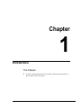
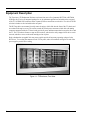
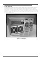
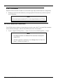
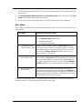
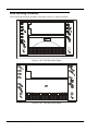
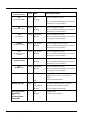
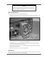
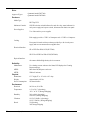
Installation and Operating Guide Tape Array 5 Rackmount Enclosure Copyright Notice Copyright ADIC 1998, 1999 The information contained in this document is subject to change without notice. This document contains proprietary information that is protected by copyright. All rights are reserved. No part of this document may be photocopied, reproduced or translated to another language without the prior written consent of ADIC™. ADIC shall not be liable for errors contained herein or for incidental or consequential damages (including lost profits) in connection with the furnishing, performance or use of this material whether based on warranty, contract, or other legal theory. Printed in the U.S.A. August 1999 Document Number 62-0115-01 Rev. D Corporate Headquarters: Advanced Digital Information Corporation Shipping Address: 11431 Willows Road NE Redmond, WA 98052 Mailing Address: P.O. Box 97057 Redmond, WA 98073-9757 Telephone: (425) 881-8004 Fax: (425) 881-2296 World-wide web: http://www.adic.com BBS: (425) 883-3211 ADIC Europe ZAC des Basses Auges 1 rue Alfred de Vigny 78112 - Fourqueux, FRANCE Telephone: 33 (0)1 30 87 53 00 Fax: 33 (0)1 30 87 53 01 ADIC Technical Assistance Center: (800) 827-2822 ADIC and ADIC Europe are trademarks of Advanced Digital Information Corporation. Quantum® is a registered trademark of Quantum Corporation. DLT™ and DLTTape™ are trademarks of Quantum Corporation. ii Copyright Notice (Europe) © Copyright ADIC Europe 1998, 1999 All rights reserved. No part of this document may be copied or reproduced in any form or by any means, without prior written permission of ADIC Europe™, ZAC des Basses Auges, 1 rue Alfred de Vigny, 78112 Fourqueux, FRANCE. ADIC Europe assumes no responsibility for any errors that may appear in this document, and retains the right to make changes to these specifications and descriptions at any time, without notice. This publication may describe designs for which patents are pending, or have been granted. By publishing this information, ADIC Europe conveys no license under any patent or any other right. ADIC Europe makes no representation or warranty with respect to the contents of this document and specifically disclaims any implied warranties of merchantability or fitness for any particular purpose. Further, ADIC Europe reserves the right to revise or change this publication without obligation on the part of ADIC Europe to notify any person or organization of such revision of change. Every effort has been made to acknowledge trademarks and their owners. Trademarked names are used solely for identification or exemplary purposes; any omissions are made unintentionally. iii EMI/RFI Compliance United States – FCC WARNING: This equipment has been tested and found to comply with the limits for a Class A digital device, pursuant to Part 15 of the FCC Rules. These limits are designed to provide reasonable protection against harmful interference in a residential installation. This equipment generates, uses, and can radiate radio frequency energy and, if not installed and used in accordance with the instructions, may cause harmful interference to radio communications. However, there is no guarantee that interference will not occur in a particular installation. If this equipment does cause harmful interference to radio or television reception (which can be determined by turning the equipment off and on) the user is encouraged to try to correct the interference by one or more of the following measures: • Re-orient or relocate the receiving antenna. • Increase the separation between the equipment and receiver. • Connect the equipment into an outlet on a circuit different from that to which the receiver is connected. • Consult the dealer or an experienced radio/TV technician for help. You may find the following booklet prepared by the Federal Communications Commission helpful: How to Identify and Resolve Radio-TV Interference Problems. This booklet is available from the U.S. Government Printing Office, Washington, DC 20402, Stock No. 004-000-00354-04. Canada – Department of Communications This digital apparatus does not exceed the Class A limits for radio noise emissions from digital apparatus as set out in the interference-causing equipment standard entitled "Digital Apparatus", ICES-003 of the Department of Communications. Cet appareil numérique respecte les limites de bruits radioélectriques applicables aux appareils numériques de Class B prescriptes dans la norme sur le matériel brouilleur: "Appareils Numériques", NMB-003 édictée par le ministre des Communications. Shielded Cables Shielded data cables are required in order to meet FCC emissions limits. The ADIC data cable meets this requirement. If you need a replacement cable, be sure to use an ADIC-approved shielded cable (to assure acceptability to FCC requirements). iv Declaration of Conformity according to EN 45014 Manufacturer’s Name: Advanced Digital Information Corporation Manufacturer’s Address: 11431 Willows Road NE Redmond, WA 98052 ZAC des Basses Auges 1 rue Alfred de Vigny 78112 - Fourqueux, France USA Type of equipment: External Digital Linear Tape Drive Enclosure Model No.: T5 Year of Manufacture: 1998 conforms to the following international specifications, as required by 89/336/EEC & 92/31/EEC: EMI: EN 50081-1, EN-55022 Class A EMC: EN 50082-1, IEC 801-2, IEC 801-3, IEC 801-4 Safety: EN 60950 Redmond, Washington USA 1 July 1998 Product Engineering Mgr. Location Date Signature/Title v Safety Warnings CAUTION RISK OF ELECTRIC SHOCK DO NOT OPEN This symbol should alert the user to the presence of "dangerous voltage" inside the product that might cause harm or electric shock. CAUTION : TO REDUCE THE RISK OF ELECTRIC SHOCK, DO NOT REMOVE COVER (OR BACK). NO USER-SERVICEABLE PARTS INSIDE. REFER SERVICING TO QUALIFIED SERVICE PERSONNEL. Caution All safety and operating instructions should be read before this product is operated, and should be retained for future reference. This unit has been engineered and manufactured to assure your personal safety. Improper use can result in potential electrical shock or fire hazards. In order not to defeat the safeguards, observe the following basic rules for its installation, use and servicing. vi 1. Heed Warnings - All warnings on the product and in the operating instructions should be adhered to. 2. Follow Instructions - All operating and use instructions should be followed. 3. Ventilation - The product should be situated so that its location or position does not interfere with proper ventilation. 4. Heat - The product should be situated away from heat sources such as radiators, heat registers, furnaces, or other heat producing appliances. 5. Power Sources - The product should be connected to a power source only of the type directed in the operating instructions or as marked on the product. 6. Power Cord Protection - The AC line cord should be routed so that it is not likely to be walked on or pinched by items placed upon or against it, paying particular attention to the cord at the wall receptacle, and the point where the cord exits from the product. 7. Object and Liquid Entry - Care should be taken to insure that objects do not fall and liquids are not spilled into the product’s enclosure through openings. 8. Servicing - The user should not attempt to service the product beyond that described in the operating instructions. All other servicing should be referred to qualified service personnel. Precautions • Do not use oil, solvents, gasoline, paint thinners or insecticides on the unit. • Do not expose the unit to moisture, to temperatures higher than 140ºF (60ºC) or to extreme low temperatures. • Keep the unit away from direct sunlight, strong magnetic fields, excessive dust, humidity, and electronic/electrical equipment, which generate electrical noise. • Hold the AC power plug by the head when removing it from the AC source outlet; pulling the cord can damage the internal wires. • Use the unit on a firm level surface free from vibration, and do not place anything on top of unit. vii Blank Page viii Table of Contents Copyright Notice ...............................................................................................................................................ii Copyright Notice (Europe) ...............................................................................................................................iii EMI/RFI Compliance ....................................................................................................................................... iv Safety Warnings................................................................................................................................................ vi Precautions ...................................................................................................................................................... vii Chapter 1 Introduction...............................................................................................................................................1 Equipment Description ......................................................................................................................................2 Rear Panel Connectors, Switches and Indicators.......................................................................................3 Power Supplies ..........................................................................................................................................4 Cooling ......................................................................................................................................................5 Chapter 2 Installation ................................................................................................................................................7 Unpacking and Inspecting .................................................................................................................................8 Installing Tape Drives........................................................................................................................................8 Installing SCSI Cables, Jumpers, and Terminators............................................................................................9 SCSI Cables and Jumpers ..........................................................................................................................9 SCSI Terminators ....................................................................................................................................10 SCSI ID Selection Switches ............................................................................................................................10 Installing in the Rack.......................................................................................................................................11 Chapter 3 Operation and Maintenance ....................................................................................................................13 Powering on the System ..................................................................................................................................16 Normal Operations ..........................................................................................................................................16 General Guidelines ..................................................................................................................................16 Drive(s) Power-on Self-Test ....................................................................................................................16 Drive Operating Conditions.....................................................................................................................18 DLT Media ..............................................................................................................................................21 Loading a Data Cartridge.........................................................................................................................22 Tape in Use..............................................................................................................................................23 Removing a Data Cartridge......................................................................................................................23 Normal Maintenance .......................................................................................................................................24 Cleaning the Drive Head..........................................................................................................................24 Cleaning the Enclosure ............................................................................................................................26 Power Supplies ........................................................................................................................................26 Chapter 4 Troubleshooting and Diagnostics............................................................................................................29 High Humidity.................................................................................................................................................32 When You Need Assistance ............................................................................................................................32 Appendix A Specifications ......................................................................................................................................33 ix Blank Page x Table of Contents Chapter 1 Introduction This Chapter. . . p provides a physical description of the switches, indicators and connectors on the rear panel of the T5 Enclosure. 1 Equipment Description The Tape Array (T5) Rackmount Enclosure can house from one to five Quantum® DLT7000 or DLT8000 SCSI tape drives in a well-integrated package for use in rackmount applications. Included on the rear panel of the T5, 10 HD68 SCSI connectors allow separate SCSI bus connections to each drive. Five drive SCSI ID selection switches are also included on the rear panel. The DLT tape drives are mounted in easily removed carriers, which slide into the front of the T5 chassis and are retained with captive screws. The carriers contain SCSI and power connectors which dock with mating connectors mounted inside the T5 chassis and provide all power and data connections between the drives and the T5. The T5 Enclosure features a snap on/off front bezel, which can be easily snapped off for drive carrier removal, and allows access to the media cartridges when in place. Dual, redundant hot-swappable 300-watt power supplies provide all necessary operating voltages for the DLT drives. Two cooling fans mounted on the T5 rear panel, and a self-contained cooling fan in each of the power supplies provide drive cooling. Front Bezel Figure 1-1: T5 Enclosure, Front View 2 Introduction Rear Panel Connectors, Switches and Indicators Drive SCSI ID Switches AC Power Connector PS Status Indicators Power Switch SCSI I/O Connectors Figure 1-2: T5 Rear Panel Rear Panel Connectors, Switches and Indicators Power Switch Turns on AC power to the T5 Enclosure. AC Power Connector Plug the T5 Enclosure AC power cord into this connector. SCSI I/O Connectors Connections for the interface cable, SCSI jumpers, and/or SCSI terminators, which are used to connect the T5 Enclosure to the host computer SCSI bus(ses) or to other devices on the SCSI channel. Ten HD68 connectors allow a separate SCSI bus connection to each drive installed in the T5 Enclosure. Drive SCSI ID Switches Sets the SCSI ID for each drive. Power Supply Status Indicators Illuminates when power is applied, and the power supply is operational. Extinguishes whenever the power supply becomes non-operational, or power is removed. Introduction 3 Power Supplies Two redundant hot-swappable 300-watt power supplies provide operating voltages for the DLT tape drives installed in the T5 Enclosure. The two supplies operate in parallel using proprietary power control and sharing modules. Each supply plugs into the rear of the T5 and can be removed or replaced while the other supply keeps the system fully operational. There is a normally green indicator on the T5 rear panel, at the top of each power supply module, which extinguishes whenever the associated power supply fails, is turned off, or is removed from the chassis. Power Supplies Figure 1-3: T5 Rear Panel 4 Introduction Cooling The T5 enclosure is cooled by four fans, two of which are contained in the power supply modules and whose status is reflected by the power supply status indicators. The other two fans are mounted on the chassis rear panel and are easily removed and replaced while the system remains in operation. Power Supply Fans Chassis Fans Figure 1-4: T5 Rear Panel Introduction 5 Blank Page 6 Introduction Chapter 2 Installation This Chapter. . . p explains the steps necessary to install your T5 enclosure. 7 Unpacking and Inspecting Unpack the T5 chassis and visually inspect for any damage that might have occurred during shipment. Retain the shipping carton in case reshipment is necessary. Remove the top cover of the chassis and inspect the power supplies and cabling for component damage. If any damage has occurred, notify ADIC immediately. Each shipping carton should contain the following: • A T5 Enclosure chassis with two removable power supply assemblies and internal SCSI data cables, as ordered. • Accessories box containing this Installation and Operating Guide, a right and a left side rack mount support bracket, and an accessory bag containing an AC power cord and hardware necessary to rack mount the enclosure. Installing Tape Drives 1. Insert each drive carrier assembly into the unit. Check the carrier to insure proper docking connections. 2. Fully tighten the captive screw at the top and bottom of the carrier to secure it in the T5 chassis. Caution When inserting a carrier, be sure that the orientation of the carrier is correct. The SCSI data cable connector should be nearest the top of the chassis. 8 Installation Installing SCSI Cables, Jumpers, and Terminators Follow the steps on the following pages to connect your T5 to one or more SCSI busses. This involves installing SCSI cables, jumpers (daisy chain cables), and terminator(s) onto the SCSI I/O connectors on the rear panel of the T5. Note The interface cable(s) must be shielded – ADIC can supply you with the correct type(s). The T5 Enclosure can contain up to five SCSI DLT tape drives. Listed below are the SCSI configurations supported by the T5 Enclosure: • Each DLT drive can be connected to a separate SCSI bus, or from two to five drives can be daisychained together and connected to the same SCSI bus. • Each SCSI bus can be either single-ended or differential. They must each match the SCSI host they are connected to. • Termination can be active or passive. ADIC recommends using active termination on a single-ended bus. • All termination must be external. Never use internal terminators to terminate the drives. SCSI Cables and Jumpers 1. Attach one end of the SCSI interface cable(s) to the connector(s) shown on the rear of your T5 Enclosure. Press firmly and secure the jackscrews. 2. Attach the other end of the SCSI interface cable(s) to the external connector(s) on the SCSI interface card(s). Press firmly and secure the jackscrews. Note The jackscrews at both ends of the SCSI cable must be securely fastened in order for the drives to communicate properly with the host computer. 3. If daisy-chaining two or more drives together for connection to a single SCSI bus, attach one end of the SCSI jumper cable to one of the drives. 4. Attach the other end of the SCSI jumper cable to the external connector on an adjacent drive. Installation 9 SCSI Terminators External SCSI bus terminators should be used with either single-ended or differential drive configurations. 1. Install any required external terminator(s) on the appropriate SCSI connector(s) on the rear panel of your T5 Enclosure. Note A drive should only be terminated if it is the last physical device on a SCSI bus. SCSI ID Selection Switches The SCSI ID selection switches are located at the top, near the center of the T5 rear panel. Each switch has sixteen positions (0 through 15) and the selected ID is shown in the switch window. 1. To select a higher SCSI ID, push the “+” button. To select a lower SCSI ID, push the “-” button. Notes 10 • Each device attached to an individual SCSI channel must be assigned a unique SCSI ID. • SCSI IDs are preset at the factory to the following: Drive 1 = 1, Drive 2 = 2, Drive 3 = 3, Drive 4 = 4, Drive 5 = 5. Installation Installing in the Rack Perform the following procedure to install your T5 Enclosure in a standard 19" rack: 1. Remove the hardware components from the accessories bag. 2. Verify that the following components are included: Quantity 3. Component 10 Captive nut (cage nut), 10-32, slip-on 10 Captive nut (cage nut), 10-32, snap-in 12 Screw, Phillips, 10-32 x ½” 12 Washer, flat, # 10 12 Washer, lock, # 10 Locate the left- and right-side rack mount support brackets. The rack mount support brackets are secured to your racks rear vertical rails with four 10-32 x ½” Phillips screws and 10-32 cage nuts. 4. Install two cage nuts in each of the racks rear vertical rails (as shown below) by either snapping them into, or slipping them into the holes in each rail. The cage nuts need to be vertically spaced to secure each support bracket using a lower and an upper mounting slot. Rear Vertical Rails Front of Rack Installation 11 5. Secure the right and left side rack mount support brackets to the racks rear vertical rails using a 10-32 x ½” Phillips screw in each cage nut as shown below. Front of Rack Support Brackets Rear Vertical Rails The T5 Enclosure is secured to your racks front vertical rails with four 10-32 x ½” Phillips screws and 10-32 cage nuts. 12 6. Install two cage nuts in each of the racks front vertical rails by either snapping them into, or slipping them into the holes in each rail. The cage nuts should be at the same vertical height as those securing the support brackets. 7. Remove the front bezel from the T5 Enclosure. It is held in place by four ball studs. Simply pull the bezel off of the ball studs and set it aside. 8. If necessary, obtain assistance to hold your T5 Enclosure chassis in the rack where it will be located. The rack mount support brackets are designed to support the rear of the T5 chassis. Place the T5 Enclosure so that it rests on the support brackets at the rear. Installation 9. Secure your T5 Enclosure to your racks front vertical rails using a 10-32 x ½” Phillips screw through each cage nut as shown below. Front of Rack 10. Secure the bezel to the T5 Enclosure by placing it over the ball studs and pushing firmly until it snaps into place. Installation 13 Blank Page 14 Installation Chapter 3 Operation and Maintenance This Chapter. . . p explains how to operate the T5 Enclosure. 15 Powering on the System 1. Plug the power cord into the back of your T5 Enclosure. 2. Plug the power cord from the T5 Enclosure into a grounded electrical outlet. Use caution when plugging the power cord into an electrical outlet. Hazardous voltages are present in the sockets of the outlet. 3. Plug the power cord from your host computer into a grounded electrical outlet. Turn on the power switch located on the rear panel of the T5 Enclosure. Turn on the host computer power. When the drives have completed their boot and initialization processes they are On-line on the appropriate SCSI bus(ses). Normal Operations General Guidelines Once your T5 Enclosure and your choice of application software are installed and configured, you can automatically perform backup and restore operations via the application software. You do not need to intervene unless the application software instructs you to exchange data cartridges. Always follow these general-operating guidelines: p Use only the recommended types of media cartridges described in this manual. p Clean each of the DLT drives once a month, or whenever the Use Cleaning Tape LED is illuminated on a drive front panel. Drive(s) Power-on Self-Test When you power up your T5 Enclosure, the DLT drives each perform a Power-on Self-Test (POST) while the library is performing the Power-Up Checks. The sequence of events for each drive is: 1. 16 The LEDs on the right front panel of the drive will turn on sequentially from top to bottom. All LEDs will remain ON for a few seconds. Operation and Maintenance 2. The LEDs on the left front panel of the drive will turn ON at the same time for about three seconds and then turn OFF. 3. The Operate Handle, Write Protected, and Use Cleaning Tape LEDs will turn OFF. The Tape in Use LED will blink while the tape drive initializes. 4 If your external SCSI bus terminator(s) have a Term Power LED it should also be illuminated. Drive Status After completion of the drive POST and initialization, each drive will be in one of the four states listed in the following table: Drive State 1. No cartridge is present Indicator Displays and Actions A. The Tape in Use LED turns OFF. B. The Operate Handle LED turns ON. C. The handle is unlatched. D. The drive beeps momentarily. 2. A cartridge is present and the handle is closed. The drive loads the cartridge. When the Tape in Use LED stops blinking and stays ON, the tape’s actual density lights. For example, if the actual tape density is 2.6, then the LED turns ON next to the 2.6 label. When the Density Override LED blinks, you can select a density. The drive is ready for use. 3. A cartridge is present, but the handle is open. The Tape in Use LED turns OFF. The Operate Handle LED flashes. When the Tape in Use LED stops blinking and stays ON, the tape’s actual density lights. For example, if the actual tape density is 2.6, then the LED turns ON next to the 2.6 label. When the Density Override LED blinks, you can select a density. The drive is ready for use. 4. The drive detects an error condition. Then all right or left side LEDs blink repeatedly. You may try to unload the tape and reinitialize the drive by pressing the Unload key or turn power OFF and then ON again. The right or left side LEDs stop blinking and the drive tries to reinitialize. The LEDs turn ON steadily again and then turn OFF if the test succeeds. The drive POST completes in about 13 seconds on each drive, and the drives will respond normally to all commands. However, it may take longer for the media to become ready. Operation and Maintenance 17 Drive Operating Conditions Use the following illustrations and tables to determine each drive’s operating condition: Figure 3-1 DLT 7000 Drive Front Panel Figure 3-2 DLT 7000 Drive Front Panel 18 Operation and Maintenance Color State Operating Condition Write Protected Orange ON OFF Tape is write-protected. Tape is write-enabled. Tape in Use Yellow Blinking Tape is moving. Tape is loaded; ready for use. Use Cleaning Tape Yellow LED Label (Right Indicator Panel) ON Operate Handle All Right Indicator Panel LEDs, or, All Left Indicator Panel LEDs Green Drive head needs cleaning, or the tape is bad. ON Cleaning attempted, but tape expired, so cleaning Remains on after unloading cleaning not performed. tape After cleaning, turns on again when reloading data cartridge Problem data cartridge. Try another cartridge. ON OFF OK to operate the Cartridge Insert/Release Handle. Do not operate the Cartridge Insert/Release Handle. ON Blinking POST is starting. An error has occurred. (continued on next page) Operation and Maintenance 19 LED Label (Left Indicator Panel) 2.6 Color State Operating Condition Yellow ON Tape is recorded in 2.6 format. (DLT4000,DLT7000) Blinking Tape is recorded in another density. You selected this density for a write from BOT. 6.0 Yellow (DLT4000,DLT7000) 10.0 Yellow (DLT4000 only) 10.0/15.0 Yellow (DLT7000, DLT8000) 20.0 Yellow (DLT4000, DLT7000, DLT8000) 35.0 Yellow (DLT7000, DLT8000) 40.0 Yellow (DLT8000 only) Compress Density Override All Right Indicator Panel LEDs, or, all Left Indicator Panel LEDs 20 Yellow Yellow ON Tape is recorded in 6.0 format. Blinking Tape is recorded in another density. You selected this density for a write from BOT. ON (default) Tape is recorded in 10.0 format. Blinking Tape is recorded in another density. You selected this density for a write from BOT. ON (default) Tape is recorded in 10.0/15.0 format. Blinking Tape is recorded in another density. You selected this density for a write from BOT. ON (default) Tape is recorded in 20.0 format. Blinking Tape is recorded in another density. You selected this density for a write from BOT. ON (default) Tape is recorded in 35.0 format. Blinking Tape is recorded in another density. You selected this density for a write from BOT. ON (default) Tape is recorded in 40.0 format. Blinking Tape is recorded in another density. You selected this density for a write from BOT. ON Compression mode enabled. (Compression available only in 10.0, 15.0, 20.0, and 35.0 density.) OFF Compression mode disabled. ON You selected a density from the front panel. OFF (default) The host will select density (automatic). Blinking You are in density selection mode. ON Beginning POST. Blinking A POST error has occurred. Operation and Maintenance DLT Media Data Protection Warning The Write-Protect switch on the data cartridge can be moved while the cartridge is loaded into the drive. The drive will turn on the Write Protected LED immediately. However, if the drive is writing to the tape, write protect does not take effect until the write operation completes. Before loading the data cartridge, if you move the Write-Protect switch to the left, the tape is writeprotected; the Write Protected LED (orange) is ON and data cannot be written to, or erased from, the tape. Before loading the data cartridge, if you move the Write-Protect switch to the right, the tape is writeenabled and data can be written to, or erased from, the tape (if it is not software write-protected). After loading the data cartridge and during operation, if you move the Write-Protect switch from the writeprotected position (to the left) to the write-enabled position (to the right), the tape becomes write-enabled after a variable amount of time (seconds). After loading the data cartridge and during operation, if you move the Write-Protect switch from the writeenabled position (to the right) to the write-protected position (to the left), the tape becomes write-protected after a variable amount of time (seconds). Orange Indicator Write-protect Switch Write-protected Write-enabled Figure 3-2 DLT Data Cartridge Operation and Maintenance 21 Notes • A small orange rectangle is visible whenever the cartridge is writeprotected (to the left). • The orange rectangle will not be visible whenever the cartridge is writeenabled (to the right). • Store data cartridges in a dry, cool environment. • Never reset or power down your computer or T5 Enclosure while a function is in process or a tape is moving. Loading a Data Cartridge 1. If you are planning to write data to, or erase data from, the cartridge, make sure the Write-Protect switch on the cartridge is in the write-enabled position (all the way to the right). Caution A data cartridge can only be loaded when the Operate Handle LED is ON. Do not attempt to open the Cartridge Insert/Release Handle unless this LED is ON steady. 22 2. Lift up on the Cartridge Insert/Release Handle. 3. Insert the data cartridge into the slot. 4. Push the cartridge into the drive. 5. Push the Cartridge Insert/Release Handle closed. The drive will go on-line. 4 A load sequence will initiate where the Operate Handle LED will turn OFF and the Tape in Use LED will blink while the drive moves the tape to BOT (Beginning of Tape). When the tape is at BOT, the Tape in Use LED will turn ON steady. Additionally, one of the compression Density LEDs on the Left Indicator Panel may be illuminated or blinking. The tape is now ready for use. Operation and Maintenance Tape in Use Whenever the Tape in Use LED (yellow) is ON steady, the tape is ready to use. When the tape is being read, written, or rewound, Tape in Use blinks. Use the following table to determine what is happening during cartridge use: Right Indicator Panel LED State Tape in Use ON steady Blinks irregularly Blinks regularly Meaning A cartridge is loaded, but the tape is not moving. This can mean no application is communicating with the controller, or that the application is communicating but is not delivering commands for tape motion. A read or write is in progress. Tape is loading, unloading, or rewinding. Operate Handle ON and beeper sounds Tape is unloaded into the cartridge and the cartridge can now be removed, or if the drive is unloaded, a cartridge can now be inserted. All LEDs Blinking An error has occurred during operation. Removing a Data Cartridge Caution Remove a cartridge from the drive before turning OFF host system power. Failure to remove a cartridge before turning OFF host system power can result in cartridge and drive damage. To unload a cartridge from the drive perform the following steps: 1. Push the Unload button. 4 The Tape in Use LED will blink as the tape rewinds. Caution A data cartridge can only be unloaded when the Operate Handle LED is ON. Do not attempt to open the Cartridge Insert/Release Handle unless this LED is ON steady. 2. When the Operate Handle LED is ON (and the beeper has sounded), pull the Cartridge Insert/Release Handle open to eject the cartridge from the drive. Operation and Maintenance 23 3. Remove the cartridge. 4. Push the Cartridge Insert/Release Handle closed. Caution When you remove the cartridge from the drive, return the cartridge to its plastic case to prolong the cartridge life. Normal Maintenance Cleaning the Drive Head Cleaning the head should always be performed as the first step if the Use Cleaning Tape LED is illuminated on the drive. Note The cleaning cartridge is exhausted after it has performed 20 cleanings. The cleaning tape includes a label with 20 small boxes printed on it. Always place a check mark in a box each time the tape performs a cleaning. Replace the cleaning cartridge when it has performed 20 cleanings (all boxes will be checked). No routine maintenance is required apart from periodically cleaning a drive head whenever the appropriate Use Cleaning Tape LED is illuminated. 24 Operation and Maintenance The following table tells you when to use the cleaning tape: If . . . It means . . . You should . . . 1. The drive head needs cleaning or the tape is bad Use the cleaning cartridge. Load the cleaning cartridge using the procedure in Loading the Data Cartridge in Chapter 3, Operations. While using a data cartridge, the Use Cleaning Tape LED illuminates. When cleaning is complete, the beeper will sound alerting you to remove the cleaning cartridge. Follow the Removing the Data Cartridge procedure in Chapter 3, Operations to remove the cleaning cartridge from the drive. Back up the data from this cartridge onto another cartridge, it may be damaged. A damaged cartridge may cause unnecessary use of the cleaning cartridge. 2. While using a data cartridge, the Use Cleaning Tape LED begins to blink. 3. Use Cleaning Tape LED Your data cartridge may be causing the problem still illuminates after you clean the drive head. Try another data cartridge. 4. Use Cleaning Tape LED Cleaning has not been accomplished and the cleaning illuminates after you load cartridge has no remaining the cleaning cartridge cycles available. Replace the cleaning cartridge. The data cartridge may be damaged Caution Using cloth swabs, cotton swabs, cleaning agents, or unapproved cleaning cartridges will void your warranty. To clean the head, use a cleaning cartridge. Insert the cleaning cartridge in the drive following the Loading the Data Cartridge procedure described earlier in this chapter. The drive will automatically clean the head. When the cleaning operation is complete, the drive will illuminate the Operate Handle LED alerting you to remove the cleaning cartridge. Caution Do not remove the cleaning cartridge before the drive sounds the beeper. Follow the Removing the Data Cartridge procedure described earlier in this chapter to remove the cleaning cartridge from the drive. Operation and Maintenance 25 Note If you load the cleaning cartridge into the drive after it has exhausted its cleaning cycles, it will not clean the head (the cycle is noticeably shorter) and the Use Cleaning Tape LED will be illuminated. Be sure to replace the cleaning cartridge when the cleaning cycle is noticeably shorter. Cleaning the Enclosure The outside of the enclosure can be cleaned with a damp towel. If you use a liquid all-purpose cleaner, apply it to the towel. Do not spray the enclosure. Power Supplies Introduction The T5 comes with two "hot-swappable" 300-watt power supplies. Each auto-sensing (90 to 230 VAC, 50 to 63 Hz) supply provides operating voltages of +5 V @ 30 A and +12 V @ 14 A. Either supply will power the chassis in the event that the other ceases to function. This is particularly important for DLTTM drives since data loss can occur as a result of a power failure. Under nominal operating conditions both power supplies provide approximately half of the chassis power, which results in extending each power supply’s mean-timebetween-failure (MTBF) rating. The power supplies are located at the rear of the T5 chassis. If either supply needs replacement, the entire power supply assembly should be unplugged and replaced. Power Supply Operation The T5 provides dual redundant power supplies, either of which can power the T5 chassis and its installed DLT drives. The power supplies normally operate in parallel and are controlled by proprietary power control and sharing circuits. In the event of a power supply failure, the surviving supply immediately assumes the full chassis load. The T5 power supplies are "hot-swappable" and can be individually removed or replaced while the system is operating. If a power supply fault occurs, or if a supply is removed or turned off, the corresponding indicator will extinguish. Note Do not operate the system with only a single power supply for any longer than is absolutely necessary. Doing so will not jeopardize the T5 in any way but it does leave all data stored on the currently loaded tapes subject to becoming unavailable. Power supply removal requires only the unfastening of three captive retaining screws. Pulling straight out on the handle will then de-couple the docking connectors and allow the supply to be taken directly out of the chassis. 26 Operation and Maintenance Caution Removal of the wrong power supply can threaten the security of stored data. Use the indicators on the rear panel of the T5 to be certain that the correct power supply is being removed. Power Supply Removal Follow this procedure below to remove a power supply module. 1. Unfasten the three captive screws that retain the supply module in the chassis. Refer to Figure 3-1 for the location of these screws. Power Supply Captive Retaining Screws Figure 3-3 Power Supplies 2. Use the handle on the module to pull the supply assembly from the chassis. The module docking connector will disengage from the chassis connector. 3. Replace the power supply module as soon as possible and make sure that the module connector mates firmly with the chassis connector. 4. Reattach the three captive screws to secure the supply module. Fan Removal Follow this procedure to remove and replace a chassis-mounted fan. The power supply fans are an integral part of the power supply modules and are not field-replaceable. Operation and Maintenance 27 1. Remove the two screws at the top of the fan, as shown in Figure 3.2 Figure 3.4 Fan Removal 2. 28 Gently pull the fan away from its mounting location. Reach inside the T5 chassis and disconnect the red DC power connectors, then remove the fan from the chassis. Operation and Maintenance DC power Connectors Figure 3.5 DC Fan Power Removal 3. Replace the fan as soon as possible making sure that the power connector on the fan is firmly mated with the DC power connector in the T5 chassis. 4. Reinstall the two screws to secure the fan to the T5 chassis. Operation and Maintenance 29 Blank Page 30 Operation and Maintenance Chapter 4 Troubleshooting and Diagnostics This Chapter. . . p describes the effects of high humidity on the T5 Enclosure. p explains what to do when you need technical support. 31 High Humidity If the drive detects high humidity, a warning is displayed by the drive LEDs. Any commands which are currently being executed are aborted, and any commands which access the tape are rejected with a CHECK CONDITION. In addition, the tape is unthreaded to prevent tape and head damage. As soon as the drive detects that the humidity is at an acceptable level, it will once again respond to commands which access the tape. To minimize the chance of condensation, please observe the following guidelines: • If you expose cartridges to temperatures outside the operating limits (5-40°C/40-113°F), stabilize them before you use them. To do this, leave the cartridges in the operating temperature for a minimum of two hours. • Avoid temperature problems by ensuring that the ventilator slots at the front of the drive and the grille on the side of the chassis are not obstructed so that the drive has adequate ventilation. • Position the drive where the temperature is relatively stable, for example, away from open windows, fan heaters, and doors. • Avoid leaving cartridges in severe temperature conditions, for example, in a car standing in bright sunlight. • Avoid transferring data (reading from and writing to cartridges) when the temperature is changing by more than 10°C per hour. When You Need Assistance When Calling the ADIC Technical Assistance Center Customer Support is provided free of charge to all ADIC customers during the ADIC Technical Assistqance Center (ATAC) hours of operation, 6:00 a.m. to 4:00 p.m. Pacific Time, Monday through Friday. Limited after hours emergency assistance is also available. Customers must provide serial numbers to qualify for this support. Warranty exchange service is available to all customers who have validated their warranty by returning the warranty card shipped with their unit, in accordance with the terms of the warranty. The following steps will help you take full advantage of your call to ADIC: 32 p Make certain that you have reviewed the documentation to solve any problems. Most questions are answered in your documentation. p Identify whether the software or hardware has worked properly at anytime before this call. Have you changed anything recently? p Pinpoint the exact location of your problem, if possible. Note the steps you took which led to the problem. Are you able to duplicate the same problem or is it a one-time occurrence? p Note any error messages displayed on your PC screen or file server. Write down the exact error message. p If at all possible, call while at your computer with your ADIC system installed and turned on. p If running on a network, have all information available (i.e., type, version #, network hardware, etc.). Troubleshooting and Diagnostics p Be prepared to provide the following information: • Your name • Company name • ADIC model number • Serial number of ADIC unit • Hardware configuration • Software configuration • A brief description of your problem • Where you purchased your ADIC system Having this information available when you call for customer support will enable ADIC to resolve your problem in the most efficient manner possible. p Call the ADIC Customer Assistance Center: (800) 827-2822. Note ADIC's telephone support services are not provided as a substitute for proper review and use of applicable ADIC user manuals. RMA (Return Material Authorization) When it has been determined that there is a hardware problem with an ADIC system, ADIC Customer Assistance Center will provide you with an RMA number. The warranty card must be completed and returned to ADIC before the warranty is valid. (Customers who have not completed warranty registration can fax the warranty card to ADIC. Call the ADIC Sales Department at (425) 881-8004 for details.) Warranty exchange service is provided at no charge to customers with validated warranties. If the item is NOT in warranty, the repairs will be billable. Therefore, we will need a PO number at the time the RMA number is issued. However, with first-time customers, it may be necessary to ship the system back C.O.D. for the first repair until credit information can be obtained by the accounting department. p Be sure all procedures in the ADIC user's manual have been checked and tried. p When calling for an RMA number have the exact ADIC model number, serial number, and a brief, descriptive explanation of the problem found. Be sure you give complete address information (e.g., any mail stops or special codes) at the time the RMA is issued. p Please send the complete ADIC system, i.e., interface cables, and the unit, if possible. A defective component as well as the unit may have caused problems itself. p The RMA number should be kept as a reference for calling to check on the status of an open RMA. It must also be written on the outside of the package for identification purposes. Troubleshooting and Diagnostics 33 Blank Page 34 Troubleshooting and Diagnostics Appendix A Specifications This Appendix . . . p contains specification information on the T5. 35 Drive: Approved Types: Quantum® model DLT7000 Quantum® model DLT8000 Enclosure Media Type: DLTTape™ IV Indicators/Controls: SCSI ID selection switch/indicator for each drive bay, status indicator for each power supply and a power switch, all mounted on chassis rear panel. Power Supplies: Two 300 watt drive power supplies Each supply provides +5 VDC at 30 amperes and +12 VDC at 14 amperes. Cooling: Front panel air intake with rear exhaust provided by a fan in each power supply and two rear-mounted hot-swappable fans. Electrical Interface: SE or HVD Fast Wide SCSI (DLT7000) SE/LVD or HVD Fast Wide SCSI (DLT8000) Physical Interface: 68-contact shielded high-density device connector Reliability Maintenance: MTBF: More than 200,000 power-on hours MTTR: Within 30 minutes Physical Dimensions: 8.75” high (5U) x 19” wide x 24” deep Weight: Approximately 185 lbs. Power Consumption: less than 40 watts Environment Electrical: 36 Use cleaning cassette whenever the Status LED displays the Cleaning Request message 90-230 vac, 50-63 Hz Temperature: 0 °C to 50° C (Operating) -20° C to 70° C (Storage/Shipping) Humidity: 20% to 80% (Operating) 0%to 95% (Storage/Shipping) Vibration: 0.25G (5-500 Hz) (Operating) 0.5G (5-500 Hz) (Storage/Shipping) Shock: 2G Operating 30G Storage/Shipping Specifications