1
Agilent 34405A
5 ½ Digit Multimeter
User’s and Service Guide
Agilent Technologies
Notices
© Agilent Technologies, Inc. 2006–2014
Warranty
No part of this manual may be reproduced in
any form or by any means (including electronic storage and retrieval or translation
into a foreign language) without prior agreement and written consent from Agilent
Technologies, Inc. as governed by United
States and international copyright laws.
The material contained in this document is provided “as is,” and is subject to being changed, without notice,
in future editions. Further, to the maximum extent permitted by applicable
law, Agilent disclaims all warranties,
either express or implied, with regard
to this manual and any information
contained herein, including but not
limited to the implied warranties of
merchantability and fitness for a particular purpose. Agilent shall not be
liable for errors or for incidental or
consequential damages in connection with the furnishing, use, or performance of this document or of any
information contained herein. Should
Agilent and the user have a separate
written agreement with warranty
terms covering the material in this
document that conflict with these
terms, the warranty terms in the separate agreement shall control.
Manual Part Number
34405-91000
Edition
Thirteenth Edition, July 3, 2014
Printed in Malaysia
Agilent Technologies, Inc.
3501 Stevens Creek Blvd.
Santa Clara, CA 95052 USA
Software Revision
This guide is valid for the firmware that was
installed in the instrument at the time of
manufacture. However, upgrading the firmware may add or change product features.
For the latest firmware and documentation,
go to the product page at:
www.agilent.com/find/34405A
Technology Licenses
The hardware and/or software described in
this document are furnished under a license
and may be used or copied only in accordance with the terms of such license.
Restricted Rights Legend
U.S. Government Restricted Rights. Software and technical data rights granted to
the federal government include only those
rights customarily provided to end user customers. Agilent provides this customary
commercial license in Software and technical data pursuant to FAR 12.211 (Technical
Data) and 12.212 (Computer Software) and,
for the Department of Defense, DFARS
252.227-7015 (Technical Data - Commercial
Items) and DFARS 227.7202-3 (Rights in
Commercial Computer Software or Computer Software Documentation).
II
Safety Notices
CAUTION
A CAUTION notice denotes a hazard. It calls attention to an operating procedure, practice, or the like
that, if not correctly performed or
adhered to, could result in damage
to the product or loss of important
data. Do not proceed beyond a
CAUTION notice until the indicated
conditions are fully understood and
met.
WA R N I N G
A WARNING notice denotes a
hazard. It calls attention to an
operating procedure, practice, or
the like that, if not correctly performed or adhered to, could result
in personal injury or death. Do not
proceed beyond a WARNING
notice until the indicated conditions are fully understood and
met.
34405A User’s and Service Guide
Safety Information
Do not defeat power cord safety ground feature. Plug in to a grounded (earthed) outlet.
Do not use product in any manner not specified by the manufacturer.
Do not install substitute parts or perform
any unauthorized modification to the product. Return the product to an Agilent Technologies Sales and Service Office for service
and repair to ensure that safety features are
maintained.
Safety Symbols
WA R N I N G
Main Power and Test Input Disconnect: Unplug instrument from
wall outlet, remove power cord,
and remove all probes from all
terminals before servicing. Only
qualified, service-trained personnel should remove the cover from
the instrument.
Earth Ground
WA R N I N G
Chassis Ground
Risk of electric shock
Line and Current Protection
Fuses: For continued protection
against fire, replace the line fuse
and the current-protection fuse
only with fuses of the specified
type and rating.
WA R N I N G
Protection Limits: To avoid instrument damage and the risk of electric shock, do not exceed any of
the Protection Limits defined in
the following section.
WA R N I N G
Do not exceed any of the measurement limits defined in the
specifications to avoid instrument damage and the risk of electric shock.
WA R N I N G
Refer to manual for additional safety information
CAT II (300V) IEC Measurement Category II.
Inputs may be connected to
mains (up to 300 VAC) under
Category II overvoltage conditions.
34405A User’s and Service Guide
IEC Measurement Category II. The
HI and LO input terminals may be
connected to mains in IEC Category II installations for line voltages up to 300 VAC. To avoid the
danger of electric shock, do not
connect the inputs to mains for
line voltages above 300 VAC. See
"IEC Measurement Category II
Overvoltage Protection" on the
following page for further information.
III
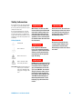
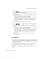
Protection Limits
The Agilent 34405A Digital Multimeter provides protection circuitry to prevent damage
to the instrument and to protect against the
danger of electric shock, provided that the
Protection Limits are not exceeded. To
ensure safe operation of the instrument, do
not exceed the Protection Limits shown on
the front panel, as defined below:
12A
Fused
V
HI
D
12A
rms
1000VDC
750VAC
500Vpk
1.2A
rms
A
LO
B
C
I
1.25A/500V FH
CAT II (300V)
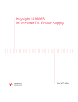
Note: The front-panel terminals and current
protection fuse are shown above.
Input Terminal Protection
Limits
Protection Limits are defined for the input
terminals:
Main Input (HI and LO) Terminals. The HI
and LO input terminals are used for voltage,
resistance, capacitance, and diode test
measurements. Two Protection Limits are
defined for these terminals:
LO to Ground Protection Limit. The LO
input terminal can safely "float" a maximum of 500 Vpk relative to ground. This is
Protection Limit "B" in the figure.
Although not shown on the figure, the Protection Limit for the HI terminal is a maximum of 1000 Vpk relative to the ground.
Therefore, the sum of the “float” voltage
and the measured voltage must not exceed
1000 Vpk
Current Input Terminal. The current input
("I") terminal has a Protection Limit of 1.2A
(rms) maximum current flowing from the LO
input terminal. This is Protection Limit "C"
in the figure. Note that the current input terminal will be at approximately the same
voltage as the LO terminal.
Note: The current-protection circuitry
includes a fuse on the front panel. To maintain protection, replace this fuse only with a
fuse of the specified type and rating.
12A Current Input Terminal. The 12A current input terminal has a Protection Limit of
12A (rms) maximum current flowing from
the LO input terminal. This is Protection
Limit "D" in the figure. Note that the current
input terminal will be at approximately the
same voltage as the LO terminal.
Note: The current-protection circuitry
includes an internal fuse. To maintain protection, service-trained personnel should
replace this fuse only with a fuse of the
specified type and rating.
IEC Measurement Category II
Overvoltage Protection
To protect against the danger of electric
shock, the Agilent 34405A Digital Multimeter provides overvoltage protection for
line-voltage mains connections meeting
both of the following conditions:
The HI and LO input terminals are connected to the mains under Measurement
Category II conditions, defined below, and
The mains are limited to a maximum line
voltage of 300 VAC.
IEC Measurement Category II includes electrical devices connected to mains at an outlet on a branch circuit. Such devices include
most small appliances, test equipment, and
other devices that plug into a branch outlet
or socket. The 34405A may be used to make
measurements with the HI and LO inputs
connected to mains in such devices, or to
the branch outlet itself (up to 300 VAC).
However, the 34405A may not be used with
its HI and LO inputs connected to mains in
permanently installed electrical devices
such as the main circuit-breaker panel,
sub-panel disconnect boxes, or permanently
wired motors. Such devices and circuits are
subject to overvoltages that may exceed the
protection limits of the 34405A.
Note: Voltages above 300 VAC may be measured only in circuits that are isolated from
mains. However, transient overvoltages are
also present on circuits that are isolated
from mains. The Agilent 34405A is designed
to safely withstand occasional transient
overvoltages up to 2500 Vpk. Do not use this
equipment to measure circuits where transient overvoltages could exceed this level.
HI to LO Protection Limit. The Protection
Limit from HI to LO ("A" in the figure at
left) is 1000 VDC or 750 VAC, which is
also the maximum voltage measurement.
This limit can also be expressed as 1000
Vpk maximum.
IV
34405A User’s and Service Guide
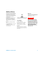
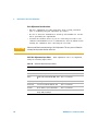
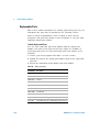
Additional Notices
Maintenance
This product complies with the WEEE Directive (2002/96/EC) marking requirement.
The affixed product label (see below) indicates that you must not discard this electrical/electronic product in domestic
household waste.
Product Category: With reference to the
equipment types in the WEEE directive
Annex 1, this product is classified as a
"Monitoring and Control instrumentation"
product.
Do not dispose in domestic household
waste.
To return unwanted products, contact your
local Agilent office, or see
www.agilent.com/environment/product
for more information.
If any portion of the Test Lead Set is worn or
damaged, do not use. Replace with a new
Agilent 34138A Test Lead Set.
The Agilent 34405A is provided with an Agilent 34138A Test Lead Set, described below.
Test Lead Ratings
Test Leads - 1000V, 15A
Fine Tip Probe Attachments - 300V, 3A
Mini Grabber Attachment - 300V, 3A
SMT Grabber Attachments - 300V, 3A
Operation
WA R N I N G
If the Test Lead Set is used in a
manner not specified by Agilent
Technologies, the protection provided by the Test Lead Set may be
impaired. Also, do not use a damaged or worn Test Lead Set.
Instrument damage or personal
injury may result.
The Fine Tip, Mini Grabber, and SMT Grabber attachments plug onto the probe end of
the Test Leads.
34405A User’s and Service Guide
V
Declaration of Conformity (DoC)
The Declaration of Conformity (DoC) for this instrument is available on the Web site. You can
search the DoC by its product model or description.
http://regulations.corporate.agilent.com/DoC/search.htm
NOTE
VI
If you are unable to search for the respective DoC, please contact your local Agilent
representative.
34405A User’s and Service Guide
Contents
1
2
34405A User’s and Service Guide
Getting Started Tutorial 11
Introducing the Agilent 34405A Multimeter 12
Checking the Shipping Contents 13
Connecting Power to the Multimeter 13
Adjusting the Handle 14
The Front Panel at a Glance 15
The Display at a Glance 16
The Rear Panel at a Glance 17
Remote Operation 18
Configuring and Connecting the USB Interface
SCPI Commands 18
Making Measurements 20
Measuring AC or DC Voltage 20
Measuring Resistance 21
Measuring AC (RMS) or DC Current up to 1.2A
Measuring AC (RMS) or DC Current up to 12A
Measuring Frequency 22
Testing Continuity 23
Checking Diodes 23
Measuring Capacitance 24
Measuring Temperature 24
Selecting a Range 25
Setting the Resolution 26
Features and Functions
Math Operations 28
Null 29
dBm 29
dB 30
Min/Max 30
Limit 31
Hold 31
18
21
22
27
VII
Contents
Math Annunciators 32
Using the Secondary Display 33
Measurement Functions and the Secondary Display
Math Operations and the Secondary Display 35
33
Using the Utility Menu 36
Changing Configurable Settings 37
Reading Error Messages 38
The Beeper 39
Editing Values in the Secondary Display 40
Selecting the Value to Edit 40
Editing Values 40
Storing and Recalling Instrument States 41
Storing a State 41
Recalling a Stored State 42
Reset/Power-On State 43
Triggering the Multimeter 45
VIII
3
Measurement Tutorial 47
DC Measurement Considerations 48
Noise Rejection 49
Resistance Measurement Considerations 51
AC Measurements 52
True RMS AC Measurements 53
Other Primary Measurement Functions 56
Frequency Measurement Errors 56
DC Current Measurements 56
Capacitance Measurements 57
Temperature Measurements 58
Other Sources of Measurement Error 59
4
Performance Tests and Calibration 63
Calibration Overview 64
Closed - Case Electronic Calibration 64
Agilent Technologies Calibration Services
Calibration Interval 64
Time Required for Calibration 65
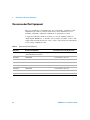
Recommended Test Equipment 66
64
34405A User’s and Service Guide
Contents
Test Considerations 67
Input Connections 67
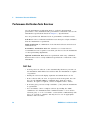
Performance Verification Tests Overview 68
Self -Test 68
Quick Performance Check 69
Performance Verification Tests 70
Zero Offset Verification 71
Gain Verification 73
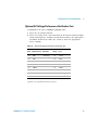
Optional AC Voltage Performance Verification Test 79
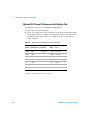
Optional AC Current Performance Verification Test 80
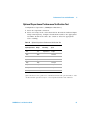
Optional Capacitance Performance Verification Test 81
Calibration Security 82
Unsecuring the Instrument for Calibration 83
Calibration Process 85
Using the Front Panel for Adjustments 86
Adjustments 88
Zero Adjustment 88
Gain Adjustments 89
DC Voltage Gain Adjustment Procedure 91
DC Current Gain Adjustment Procedure 92
AC Voltage Gain Adjustment Procedure 94
AC Current Gain Adjustment Procedure 95
Ohms Gain Adjustment Procedure 97
Frequency Gain Adjustment Procedure 98
Capacitance Gain Adjustment Procedure 99
Finishing the Adjustments 101
Calibration Message 102
To Read the Calibration Count 102
Calibration Errors 103
5
34405A User’s and Service Guide
Disassembly and Repair 105
Operating Checklist 106
Types of Service Available 107
Repackaging for Shipment 108
Cleaning 108
To Replace the Power Line Fuse 109
To Replace a Current Input Fuse 110
Electrostatic Discharge (ESD) Precautions
112
IX
Contents
Mechanical Disassembly
Replaceable Parts 120
Rack Mounting 121
6
Specifications 123
DC Specifications[1] 125
AC Specifications[1] 126
Temperature and Capacitance Specifications[1] 128
Operating Specifications 129
Supplemental Measurement Specifications 130
General Characteristics 134
To Calculate Total Measurement Error 136
Accuracy Specifications 137
Configuring for Highest Accuracy Measurements
Index
X
113
138
139
34405A User’s and Service Guide
Agilent 34405A 5 ½ Digit Multimeter
User’s and Service Guide
1
Getting Started Tutorial
Introducing the Agilent 34405A Multimeter 12
Checking the Shipping Contents 13
Connecting Power to the Multimeter 13
Adjusting the Handle 14
The Front Panel at a Glance 15
The Rear Panel at a Glance 17
Measuring AC or DC Voltage 20
Measuring Resistance 21
Measuring AC (RMS) or DC Current up to 1.2A 21
Measuring AC (RMS) or DC Current up to 12A 22
Measuring Frequency 22
Testing Continuity 23
Checking Diodes 23
Measuring Capacitance 24
Measuring Temperature 24
Selecting a Range 25
Setting the Resolution 26
This chapter contains a quick tutorial showing how to use
the front panel to make measurements.
Agilent Technologies
11
1
Getting Started Tutorial
Introducing the Agilent 34405A Multimeter
The multimeter’s key features are:
• 5 ½- digit dual display measurements
• Ten measurement functions:
• AC voltage
• DC voltage
• Two- wire resistance
• AC current
• DC current
• Frequency
• Continuity
• Diode Test
• Temperature
• Capacitance
• Six math functions:
• Null
• dBm
• dB
• Min/Max
• Limit
• Hold
• 4 ½- or 5 ½- digit measurements
• Dual display
• USB 2.0, USBTMC- USB488 device class
12
34405A User’s and Service Guide
Getting Started Tutorial
1
Checking the Shipping Contents
Verify that you have received the following items with your multimeter:
• One test lead kit
• One power cord
• One USB interface cable
• A Quick Start Guide
• A Certificate of Calibration (test report included)
• A CD- ROM containing the remote programming online help, online
manuals, application software, and instrument drivers
• An Agilent IO Library CD- ROM
If anything is missing, contact your nearest Agilent Sales Office.
Connecting Power to the Multimeter
Connect the power cord and press the Power switch to turn on the
multimeter.
The front- panel display illuminates while the multimeter performs its
power- on self- test. (If the multimeter does not power- on, refer “Operating
Checklist” on page 106).
The multimeter powers up in the DC voltage function with autoranging
enabled. If self- test is successful, the multimeter goes to normal operation.
If the self- test is not successful, Error is displayed on the left side of the
display and an error number is displayed in the upper right side of the
display. In the unlikely event that self- test repeatedly fails, contact your
nearest Agilent Sales Office.
NOTE
A more extensive self-test is available from the Utility menu see “Using the Utility
Menu” on page 36 for details.
34405A User’s and Service Guide
13
1
Getting Started Tutorial
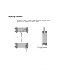
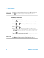
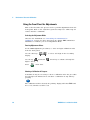
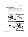
Adjusting the Handle
To adjust the handle, grasp the handle by the sides and pull outward.
Then, rotate the handle to the desired position.
Benchtop Positions
Carrying Position
14
34405A User’s and Service Guide
Getting Started Tutorial
1
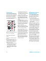
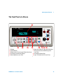
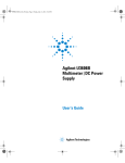
The Front Panel at a Glance
1
s
Agilent
34405A
5 ½ Digit Multimeter
12A
Fused
V
HI
mV DC
Range
12A
rms
1000VDC
750VAC
500Vpk
1.2A
rms
mV DC
LO
Power
Cont )))
DCV
4
DCI
Auto
Freq
ACV
ACI
Range
Digits 5
Temp
dB
dBm
Enter
Null
MnMx
Disp
Hold
Utility
Store
Recall
Limit
Edit
2
1
2
3
4
5
3
4
Display
On/Off Switch
Measurement Function and Resolution Keys
Autorange and Manual Range
Math Operations and Edit
34405A User’s and Service Guide
5
I
1.25A/500V FH
Shift
CAT II (300V)
Local
6
7
8
9
6 State Store/Recall, Utility and Edit Keys
7 Shift (selects blue shifted keys) and
Local key
8 Secondary Display Key
9 Input Terminals and Current Fuse
15
1
Getting Started Tutorial
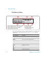
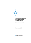
The Display at a Glance
5
6
7
Remote ManRng Hold Limit Null MnMx
°C °F dBm
Mk
Hz μnF
mVA DC AC
CAL
°C °F dBm
Mk Hz μnF
mVA DC AC
MaxMinAvgN Ref R Value
Range
Store Recall HiLo Limit
Shift
2
3
4
1
1
2
3
4
Primary Measurements and CAL Annunciator
Primary Measurement Function and Units
Math and State Storage Annunciators
Range and Shift Annunciators
5 System Annunciators
6 Secondary Display
7 Secondary Measurement
Function and Units
The System Annunciators (above the primary display) are described below
(see page 32 for Math Annunciators and Chapter 4 for the calibration
annunciator).
System Annunciator
Description
*
Sample annunciator--indicates readings being taken.
Remote
The multimeter is operating in the remote interface mode.
ManRng
Fixed range selected (autoranging disabled).
Hold
Reading hold function enabled.
Limit
Limit math feature enabled
Null
Null math feature enabled.
MnMx
Min/Max feature enabled.
Continuity test function selected.
Diode test function selected.
Shift
16
Shift key has been pressed.
34405A User’s and Service Guide
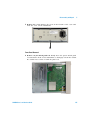
Getting Started Tutorial
1
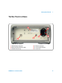
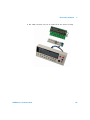
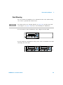
The Rear Panel at a Glance
2
6
4
1
1 USB Interface Connector
2 Model and Serial Number Label
3 Chassis Ground Lug
34405A User’s and Service Guide
5
3
4 AC Power Connector
5 AC Line Voltage Selector
6 AC Line Fuse
17
1
Getting Started Tutorial
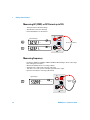
Remote Operation
The instrument automatically enters the Remote state whenever SCPI
commands are received over the USB bus interface. When in the Remote
state, pressing
Shift
returns the multimeter to front panel operation.
Local
Configuring and Connecting the USB Interface
There is nothing to configure on your instrument for a USB connection.
Just connect the instrument to your PC using the USB 2.0 cable included
with the instrument.
NOTE
To easily configure and verify an interface connection between the 34405A and your PC,
use the Automation–Ready CD, which is shipped with your 34405A. This CD includes the
Agilent IO Libraries Suite and the Agilent Connection Expert application. For more
information about Agilent's I/O connectivity software, visit www.agilent.com/find/iolib.
SCPI Commands
The Agilent 34405A complies with the syntax rules and conventions of
SCPI (Standard Commands for Programmable Instruments).
NOTE
18
For a complete discussion of 34405A SCPI syntax, refer to the Agilent 34405A
Programmer’s Reference Help, This help is provided on the Agilent 34405A Product
Reference CD-ROM that came with your instrument.
34405A User’s and Service Guide
Getting Started Tutorial
1
SCPI Language Version
You can determine the multimeter’s SCPI language version by sending the
SYSTem:VERSion? command from the remote interface.
• You can query the SCPI version from the remote interface only.
• The SCPI version is returned in the form “YYYY.V”, where “YYYY”
represents the year of the version, and “V” represents a version number
for that year (for example, 1994.0).
34405A User’s and Service Guide
19
1
Getting Started Tutorial
Making Measurements
The following pages show how to make measurement connections and how
to select measurement functions from the front panel for each of the
measurement functions.
For remote operation, refer to the MEASure Subsystem in the Agilent
34405A Online Programmer’s Reference online help.
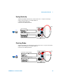
Measuring AC or DC Voltage
AC Voltage:
• Five Ranges: 100.000 mV, 1.00000 V, 10.0000 V, 100.000 V, 750.00 V
• Measurement Method: AC coupled true rms - measures the AC component with up to 400 VDC
bias on any range.
• Crest Factor: Maximum 5:1 at full scale
• Input Impedance: 1 MΩ ± 2% in parallel with <100pF on all ranges
• Input Protection: 750V rms on all ranges (HI terminal)
DC Voltage:
•
•
•
•
Five Ranges: 100.000 mV, 1.00000 V, 10.0000 V, 100.000 V, 1000.00 V
Measurement Method: Sigma Delta A-to-D converter
Input Impedance: ~10 MΩ all ranges (typical)
Input Protection: 1000V on all ranges (HI terminal)
12A
Fused
Typical ACV Display:
V
HI
mV
ACV
AC
Range
mV
12A
rms
1000VDC
750VAC
500Vpk
1.2A
rms
AC
LO
Typical DCV Display:
DCV
mV DC
-
I
mV DC
Range
+
AC or DC Voltage Source
1.25A/500V FH
CAT II (300V)
20
34405A User’s and Service Guide
Getting Started Tutorial
1
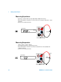
Measuring Resistance
• Seven Ranges: 100.000Ω, 1.00000 kΩ, 10.0000 kΩ, 100.000 kΩ, 1.00000 MΩ, 10.0000 MΩ, 100.000
MΩ
• Measurement Method: two-wire ohms
• Open-circuit voltage limited to < 5 V
• Input protection 1000 V on all ranges (HI terminal)
12A
Fused
Test
Current
V
Typical Display:
HI
12A
rms
1000VDC
750VAC
Range
Resistance
LO
1.2A
rms
500Vpk
I
1.25A/500V FH
CAT II (300V)
Measuring AC (RMS) or DC Current up to 1.2A
• Three AC Current or DC Current Ranges: 10.0000 mA, 100.000 mA, 1.00000 A
• Shunt Resistance: 0.1Ω to 10 Ω for 10mA to 1A ranges
• Input Protection: Front Panel 1.25A, 500V FH fuse for I terminal
12A
Fused
V
Typical ACI Display:
HI
ACI
mA
AC
Range
mA
1000VDC
750VAC
500Vpk
1.2A
rms
AC
LO
Typical DCI Display:
DCI
12A
rms
m A DC
I
AC or DC Current Source
+
Range
m A DC
1.25A/500V FH
CAT II (300V)
34405A User’s and Service Guide
21
1
Getting Started Tutorial
Measuring AC (RMS) or DC Current up to 12A
• 10 Amp AC Current or DC Current Range
• Shunt Resistance: 0.01 Ω for 10A range
• Internal 15A, 600V fuse for 12A terminal
12A
Fused
V
Typical ACI Display:
HI
A
ACI
12A
rms
AC
+
1000VDC
750VAC
Range
A
AC or DC Current Source
LO
AC
Typical DCI Display:
DCI
-
1.2A
rms
500Vpk
I
A DC
Range
1.25A/500V FH
A DC
CAT II (300V)
Measuring Frequency
• Five Ranges: 100.000 mV, 1.00000 V, 10.0000 V, 100.000 V, 750.00 V. Range is based on the voltage
level of the signal, not frequency.
• Measurement Method: Reciprocal counting technique.
• Signal level: 10% of range to full scale input on all ranges
• Gate Time: 0.1 second or 1 period of the input signal, whichever is longer.
• Input Protection: 750V rms on all ranges (HI terminal)
12A
Fused
V
Typical Display:
HI
Freq
Freq
V
Hz
12A
rms
AC
1000VDC
750VAC
Range
LO
500Vpk
Frequency
Source
1.2A
rms
I
1.25A/500V FH
CAT II (300V)
22
34405A User’s and Service Guide
Getting Started Tutorial
1
Testing Continuity
•
•
•
•
Measurement Method: 0.83 mA ± 0.2% constant current source, < 5 V open circuit voltage.
Response Time: 70 samples/ second with audible tone
Continuity Threshold: 10 Ω fixed
Input Protection: 1000 V (HI terminal)
Test
Current
12A
Fused
V
Open Circuit Display:
HI
Cont )))
12A
rms
Shift
1000VDC
750VAC
LO
Typical Closed Circuit Display:
Open or
Closed
Circuit
1.2A
rms
500Vpk
I
1.25A/500V FH
CAT II (300V)
Checking Diodes
• Measurement Method: Uses 0.83 mA ± 0.2% constant current source, < 5 V open circuit voltage.
• Response Time: 70 samples/ second with audible tone
• Input Protection: 1000 V (HI terminal)
12A
Fused
Reverse Bias or Open Diode Display:
HI
12A
rms
Shift
Freq
Freq
Test
Current
V
1000VDC
750VAC
Forward Bias
LO
Typical Forward Biased Diode Display:
500Vpk
1.2A
rms
I
V DC
1.25A/500V FH
CAT II (300V)
34405A User’s and Service Guide
23
1
Getting Started Tutorial
Measuring Capacitance
• Eight ranges: 1nF, 10nF, 100nF, 1µF, 10µF, 100µF, 1000µF, 10,000µF and autorange
• Measurement Method: Computed from constant current source charge time. Typical 0.2V - 1.4V AC
signal level
• Input Protection: 1000 V (HI terminal)
12A
Fused
Typical Display:
V
+
HI
μF
μF
12A
rms
1000VDC
750VAC
500Vpk
1.2A
rms
Range
LO
Capacitance
-
I
1.25A/500V FH
CAT II (300V)
Measuring Temperature
• -80.0°C to 150.0 °C, -110.0°F to 300.0 °F
• Auto-ranging measurement, no manual range selection
• Measurement Method: 2-wire Ohms measurement of 5 kΩ thermistor sensor (E2308A) with
computed conversion
• Input Protection: 1000 V (HI terminal)
12A
Fused
Typical Display:
Temp
Temp
Test
Current
V
HI
12A
rms
°C
1000VDC
750VAC
LO
500Vpk
5k Ohm
Thermistor
1.2A
rms
I
1.25A/500V FH
CAT II (300V)
24
34405A User’s and Service Guide
Getting Started Tutorial
1
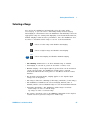
Selecting a Range
You can let the multimeter automatically select the range using
autoranging, or you can select a fixed range using manual ranging.
Autoranging is convenient because the multimeter automatically selects the
appropriate range for sensing and displaying each measurement. However,
manual ranging results in better performance, since the multimeter does
not have to determine which range to use for each measurement.
Selects a lower range and disables autoranging.
Selects a higher range and disables autoranging.
Auto
Shift
Selects autoranging and disables manual ranging.
• The ManRng annunciator is on when manual range is enabled.
• Autoranging is selected at power- on and after a remote reset.
• Manual ranging – If the input signal is greater than can be measured
on the selected range, the multimeter provides these overload
indications: OL from the front panel or “\9.9E+37” from the remote
interface.
• For frequency measurements, ranging applies to the signal’s input
voltage, not its frequency.
• The range is fixed for continuity (1 kΩ range) and diode (1 VDC range).
• The multimeter remembers the selected ranging method (auto or
manual) and the selected manual range for each measurement function.
• Autorange thresholds – The multimeter shifts ranges as follows:
Down range at <10% of current range
Up range at >120% of current range
• For remote operation, refer to the MEASure Subsystem in the Agilent
34405A Online Programmer’s Reference online help.
34405A User’s and Service Guide
25
1
Getting Started Tutorial
Setting the Resolution
You can select either 4½ or 5½- digit resolution for the DCV, DCI,
resistance, ACV, ACI and frequency measurement functions.
• 5½- digit readings have the best accuracy and noise rejection.
• 4½- digit readings provide for faster readings.
• The continuity and diode test functions have a fixed, 4½- digit display.
• Capacitance and temperature have a fixed 3½- digit display.
4
Shift
Selects 4½- digit mode.
5
Shift
Temp
Temp
Selects 5½- digit mode.
• For remote operation, refer to the MEASure Subsystem in the Agilent
34405A Online Programmer’s Reference online help.
26
34405A User’s and Service Guide
Agilent 34405A 5 ½ Digit Multimeter
User’s and Service Guide
2
Features and Functions
Math Operations 28
Using the Secondary Display 33
Using the Utility Menu 36
Editing Values in the Secondary Display 40
Storing and Recalling Instrument States 41
Reset/Power-On State 43
Triggering the Multimeter 45
This chapter contains detailed information on the multimeter
and how to use the front panel. It builds on information you
learned in the Quick Start Guide and the previous Getting
Started Tutorial Chapter.
Agilent Technologies
27
2
Features and Functions
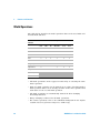
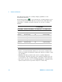
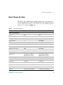
Math Operations
The table below describes the math operations that can be used with each
measurement function.
Measurement
Function
Allowed Math Operations
Null
dBm
dB
Min/Max
Limit
Hold
DCV
9
9
9
9
9
9
DCI
9
9
9
9
Ohms
9
9
9
9
ACV
9
9
9
9
ACI
9
9
9
9
Frequency
9
9
9
9
Capacitance
9
9
9
9
Temperature
9
9
9
9
9
9
Continuity
Diode
• All math operations can be toggled on and off by re- selecting the same
math operation.
• Only one math operation can be turned- on at a time. Selecting another
math operation when one is already on turns off the first operation and
then turns on the second math operation.
• All math operations are automatically turned- off when changing
measuring functions.
• Range changing is allowed for all math operations.
• For remote operation, refer to the CALCulate Subsystem in the Agilent
34405A Online Programmer’s Reference online help.
28
34405A User’s and Service Guide
Features and Functions
2
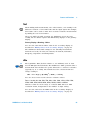
Null
Null
When making null measurements, also called relative, each reading is the
difference between a stored null value and the input signal. For example,
this feature can be used to make more accurate resistance measurements
by nulling the test lead resistance.
After you enable the Null operation, the multimeter stores the next
reading into the Offset register and immediately displays on the primary
display:
Primary Display = Reading - Offset
You can view and edit the Offset value in the secondary display as
described in “Editing Values in the Secondary Display” on page 40.
The multimeter allows Null settings for the following measurement
functions: DC Volts, AC Volts, DC Current, AC Current, Resistance,
Frequency, Capacitance and Temperature.
dBm
dBm
Shift
MnMx
The logarithmic dBm (decibels relative to one milliwatt) scale is often
used in RF signal measurements. The multimeter’s dBm operation takes a
measurement and calculates the power delivered to a reference resistance
(typically 50, 75 or 600W). The formula used for conversion from the
voltage reading is:
dBm = 10 x Log10 [ (Reading2 / RREF) / 0.001W ]
You can choose from several reference resistance values:
RREF = 2Ω, 4Ω, 8Ω, 16Ω, 50Ω, 75Ω, 93Ω, 110Ω, 124Ω, 125Ω, 135Ω, 150Ω,
250Ω, 300Ω, 500Ω, 600Ω, 800Ω, 900Ω, 1000Ω, 1200Ω, or 8000Ω.
Numeric results are in the range of ± 120.000 dBm with 0.01 dBm
resolution shown, independent of the number of digits setting.
You can view and select the RREF value in the secondary display as
described in “Editing Values in the Secondary Display” on page 40.
34405A User’s and Service Guide
29
2
Features and Functions
dB
dB
Shift
Null
Null
When enabled, the dB operation computes the dBm value for the next
reading, stores the dBm result into the dB Ref register and immediately
produces the following calculation. The first displayed reading is always
precisely 000.00 dB.
dB = 10 x Log10 [ (Reading2 / RREF) / 0.001W ] - dB Ref
• You can set dB Ref to any value between 0 dBm and \120.0000 dBm.
The default RREF is 0 dBm.
• Numeric results are displayed in the range of ± 120.000 dB with 0.01
dB resolution shown, independent of the number of digits setting.
You can view and edit the dB Ref Value in the secondary display as
described in “Editing Values in the Secondary Display” on page 40. The dB
Ref value is displayed on the secondary display in the range of ± 120.000
dBm with 0.001 dBm resolution shown.
Min/Max
MnMx
The Min/Max (Minimum/Maximum) operation stores the minimum and
maximum values, the average, and the number of readings during a series
of measurements.
When enabled, the Min/Max operation turns on the MnMx annunciator
and begins accumulating various statistics about the readings being
displayed.
Each time a new minimum or maximum value is stored, the instrument
beeps once (if the beeper is enabled) and briefly turns on the appropriate
Max or Min annunciator. The multimeter calculates the average of all
readings and records the number of readings taken since Min/Max was
enabled.
• Accumulated statistics are:
• Max- - maximum reading since Min/Max was enabled
• Min- - minimum reading since Min/Max was enabled
• Avg- - average of all readings since Min/Max was enabled
• N- - number of readings taken since Min/Max was enabled
30
34405A User’s and Service Guide
Features and Functions
2
When Min/Max is enabled, pressing Disp steps through the various Max,
Min, Avg, and N values in the secondary display. Count values display in
integer format until the maximum display value (120000) is reached after
which counts are displayed in scientific notation.
Limit
Limit
The Limit operation allows you to perform pass/fail testing against
specified upper and lower limits. You can set the upper and lower limits
to any value between 0 and \120% of the highest range for the present
function.
• You should specify the upper limit to always be a more positive number
than the lower limit. The initial factory setting for each limit is 0.
• The secondary display shows PASS when readings are within the
specified limits. The secondary display shows HI when the reading is
outside the high limit and LO when the reading is outside the low limit.
• When the beeper is ON (see “Using the Utility Menu” on page 36) the
beeper beeps on the transition from PASS to HI or PASS to LO or
when transitioning directly from HI to LO or LO to HI (no PASS in
between).
You can view and edit HI Limit and LO Limit values in the secondary
display as described in “Editing Values in the Secondary Display” on
page 40.
Hold
Hold
Shift
Limit
The reading hold feature allows you to capture and hold a stable reading
on the front panel display. When a stable reading is detected, the
multimeter emits a beep (if the beeper is enabled) and holds the reading
on the primary display. The secondary display shows the present reading.
When enabled, the Hold operation turns on the Hold annunciator and
begins evaluating readings using the rules described below:
Primary Display = ReadingN IF Max() - Min() ≤ 0.1% x ReadingN
34405A User’s and Service Guide
31
2
Features and Functions
The decision to update a new reading value in the primary display is
based upon the box- car moving statistics of the present reading and the
three previous readings as described below:
Max (ReadingN ReadingN-1 ReadingN-2 ReadingN-3)
Min (ReadingN ReadingN-1 ReadingN-2 ReadingN-3)
• Minimum delta value to trigger an update on held value : 0.1% of full scale
NOTE
• Minimum level to enable update on held value : 5% of full scale
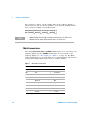
Math Annunciators
The math Hold, Limit, Null and MnMx annunciators are located above the
primary display and the dB/dBm annunciator is located right of the
primary display (see “The Display at a Glance” on page 16). The Math
Value Annunciators are located under the secondary display and assist in
viewing and editing math values in the secondary display.
Table 1
Math Value Annunciators
Math Operation When Viewing/Editing Editable
Null
Offset
9
Ref Value
dBm
RREF
9
Ref R Value
dB
dB Ref
9
Ref Value
MnMx
Maximum
Max
Minimum
Min
Average
Avg
Reading Count
N
Limit
32
Math Annunciator
HI Limit
9
Hi Limit
LO Limit
9
Lo Limit
34405A User’s and Service Guide
Features and Functions
2
Using the Secondary Display
Most measurement functions have predefined range or measurement
capabilities that can be displayed in the secondary display. All math
operations have predefined operations that are displayed on the secondary
display.
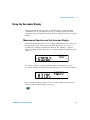
Measurement Functions and the Secondary Display
When making measurements, the secondary display allows you to show the
measurement range (for most measurement functions) or to select a
predefined secondary measurement function. For example, a typical
primary display showing DCV and a secondary display showing the DCV
range is:
mV DC
Range
mV DC
As another example, a typical primary display showing ACV and a
secondary display showing the measured frequency of the input signal is:
Hz
V
AC
The secondary display is based on the selected primary measurement
function and how many times you press:
Disp
34405A User’s and Service Guide
33
2
Features and Functions
The table below shows the secondary display capabilities for all
measurement functions.
Disp
Repeatedly pressing
cycles through the secondary display choices
for the present measurement function as shown in the table below. The
temperature, continuity and diode functions do not have secondary
displays.
.
Secondary Display
Primary Display Default Secondary Display Press Disp Key Once Press Disp Key Twice
DCV
DCV range
ACV
Off
DCI
DCI range
ACI
Off
Resistance
Resistance range
Off
Resistance Range
ACV
ACV range
Frequency
Off
ACI
ACI range
Frequency
Off
Frequency
AC Voltage Range
ACV
Off
Capacitance
Capacitance range
Off
Capacitance Range
Temperature
Off
Off
Off
Continuity
Off
Off
Off
Diode Test
Off
Off
Off
• When a second measurement function is selected, its resolution will
match the primary measurement setting and, whenever possible, it will
use autorange.
• Enabling any math operation turns off the secondary display for
measurements. All math operations offer predefined displays that can
be presented on the secondary display as described on the next page.
• For remote operation, refer to the DISPlay:WINDow2 commands in the
Agilent 34405A Online Programmer’s Reference online help.
34
34405A User’s and Service Guide
Features and Functions
2
Math Operations and the Secondary Display
When a math operation is selected, the secondary display shows the result
of the math operation or the value(s) being used by the math operation.
For example, a typical primary display showing the Limit math operation
for DCV measurements and a secondary display showing a HI limit
exceeded is:
Limit
mV DC
Disp
Repeatedly pressing
cycles through the secondary display choices
for the present math operation as shown in the table below. (Reading is
used in the table below to indicate the original measured reading value.)
Secondary Display
Math Operation Primary Display
Default Secondary Press Disp
Display
Key Once
Null
Nulled Reading
Reference Value
Off
dBm
dBm
Present Reading
RREF
Off
dB
dB
Present Reading
dB Ref (in
dBm)
Off
Min/Max
Reading
Max value
Min value
Avg value
N (count) value
Limit
Reading
PASS
HI
LO
HI Limit
LO Limit
Off
Hold
Held Reading
Present Reading
Off
34405A User’s and Service Guide
Press Disp
Key Twice
Press Disp
Press Disp
Key Three Times Key Four Times
Off
35
2
Features and Functions
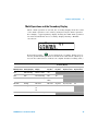
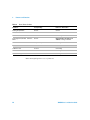
Using the Utility Menu
The Utility Menu allows you to customize a number of non- volatile
instrument configurations. It also displays error messages and hardware
revision codes. The contents of the Utility Menu are shown in the table
below.
Primary Display
Secondary
Display Settings
tESt
no
ºunit
Description
Remote Command
YES
IF YES, immediately execute self-test
upon next Store/Recall button push.
After self-test completes, returns to
normal instrument operation.
*TST? (self-test is executed
immediately)
ºC
ºF
Changes displayed units for temperature
measurements
UNIT:TEMPerature <units>
bEEP
On
OFF
Enable, disable Diode, Min/Max, Limit
Test, and Hold beep operations
SYSTem:BEEPer:STATe <mode>
P-On
rESEt
LASt
Enable or disable power-on recall of State
0 (last power-off instrument state). Note:
The multimeter always saves the
power-down state. This just determines
whether or not to recall the state at
power-on.
MEMory:STATe:RECall:AUTO <mode>
2.diSP
On
OFF
Turn the secondary display on or off.
DISPlay:WINDow2[:STATe] <mode>
StorE
On
OFF
Enable, disable all front panel state store
operation
MEMory:STATe:STORe <mode>
Edit
On
OFF
Enable, disable all math register editing
None
Error
nonE
nn.Err
See Reading Error Messages below.
SYSTem:ERRor?
CodE
1-dd.d
2-dd.d
Displays processor code revision
numbers.
1= Measurement processor revision.
2= IO processor revision.
*IDN? (from remote also returns
manufacturer's name, model number,
and the serial number)
UtitY
donE
Display donE on primary display for 1
second then return to normal operation
None
36
34405A User’s and Service Guide
Features and Functions
2
Changing Configurable Settings
The first seven items in the Utility Menu are configurable (Error and
CodE are not configurable).
Utility
1 To access the Utility Menu, press
Shift
Store
Store
Recall
Recall
.
2 The first Utility Menu selection (tESt) is shown in the primary display.
When stepping through the configurable items, the present setting for
each item is displayed in the secondary display.
3 To change the setting, use the
setting you want.
and
keys to select the
4 When the correct setting is displayed in the secondary
display, press
item.
NOTE
Edit
Store
Recall
Recall
to save the setting and advance to the next
If you set tESt to On, pressing Store/Recall immediately exits the Utility Menu and
executes self-test. If you set tESt to OFF, go on to the next step (step 5).
5 Repeat steps 4 and 5 for all items in the Utility Menu.
6 When you reach the end of the Utility Menu, the primary display shows
utitY and the secondary display briefly shows donE, after which the
multimeter returns to normal operation.
34405A User’s and Service Guide
37
2
Features and Functions
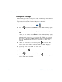
Reading Error Messages
The following procedure shows you to read error messages from the front
panel. For remote operation, refer to the SYSTem:ERRor? command in the
Agilent 34405A Online Programmer’s Reference online help.
Utility
1 To access the Utility Menu, press
2 Press
Edit
Store
Recall
Recall
Shift
Store
Store
Recall
Recall
seven times until Error is shown in the primary display.
3 If there are no errors in the error queue, the secondary display shows
nonE.
If there are one or more errors, Error is shown in the primary display
and nn.Err is shown flashing in the secondary display (where nn is the
total number of errors in the error queue). For example, if there are
three errors in the queue, 03.Err will flash in the secondary display.
Errors are numbered and stored in the queue in the order they
occurred.
4 If there are errors in the error queue, press
to read the first
error. The error number in the queue is shown in the primary display
and the actual error number is shown in the secondary display.
5 Repeat step 4 for all errors in the error queue
(you can also use
to view the previous error).
6 After reading all errors,
press
Edit
Store
Recall
Recall
twice to exit the Utility Menu.
7 The error queue is automatically cleared after
and the utility menu is exited.
38
has been pressed
34405A User’s and Service Guide
Features and Functions
2
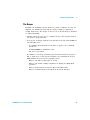
The Beeper
Normally, the multimeter beeps whenever certain conditions are met (for
example, the multimeter beeps when a stable reading is captured in
reading hold mode). The beeper is factory set to ON, but may be disabled
or enabled manually.
• Turning off the beeper does not disable the key click generated when
you press a front- panel key.
• A beep tone is always emitted (even with the beep state turned OFF) in
the following cases.
• A continuity measurement is less than or equal to the continuity
threshold.
• A SYSTem:BEEPer command is sent.
• An error is generated.
• In addition to the beep operations just described, when the beeper is
ON, a single beep occurs for the following cases (turning the beeper
OFF disables the beep for the following cases):
• When a new Min or Max value is stored
• When a new stable reading is updated on display for Math Hold
operation
• When a measurement exceeds the HI or LO Limit value
• When a forward- biased is measured in the Diode function
34405A User’s and Service Guide
39
2
Features and Functions
Editing Values in the Secondary Display
Many Math function values are editable in the secondary display. The
table below describes key operations during number editing. These rules
also apply for editing within the Utility menu.
You can edit the values used for the Null, Limit, dB or dBM math
function. For remote operation, refer to the CALCulate Subsystem in the
Agilent 34405A Online Programmer’s Reference online help.
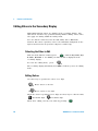
Selecting the Value to Edit
Disp
With the math function enabled, press
until the Ref Value, Ref
R Value, Hi Limit or Lo Limit you want to edit is displayed in the
secondary display.
To select the editing mode, press:
Limit
Edit
The secondary display will briefly show Edit to indicate you are in editing
mode.
Editing Values
Use these keys to position the cursor on a digit:
Limit
Edit
Edit
Store
Recall
Recall
Moves cursor to the left
Moves cursor to the right
When the cursor is positioned on a digit, use these keys to edit the value:
Increments digit
Decrements digit
When done editing, save the new value by pressing:
40
Disp
34405A User’s and Service Guide
Features and Functions
2
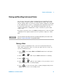
Storing and Recalling Instrument States
You can save and recall complete instrument states including all front
panel settings, all math registers, all Utility Menu settings, and all bus
specific settings. There are four user storage registers numbered 1 through
4. An additional state, state 0, is managed by the instrument and stores
the last power- down state. The instrument automatically saves the
complete instrument configuration to State 0 whenever a power- down
event occurs.
For remote operation, refer to the MEMory Subsystem, the *SAV, and *RCL
commands in the Agilent 34405A Online Programmer’s Reference online
help.
NOTE
The store function in the utility menu must be enabled (On) before you can store states.
Refer to “Using the Utility Menu” on page 36 for details.
Storing a State
Before storing an instrument state, select the measurement function,
range, math operations, and so on, that you want saved as a state. To
store the instrument state:
Store
Recall
1 Press Recall
flashing.
2 Press
3 Press
, the display Store and Recall annunciators will begin
until only the Store annunciator is flashing.
or
Store
Recall
Recall
again.
4 Press
or
until the state number (1- 4) you want to use is
shown flashing in the secondary display.
Store
5 Press Recall
to store the state. The secondary display briefly shows
donE when the state is successfully saved.
34405A User’s and Service Guide
41
2
Features and Functions
NOTE
To escape the recall operation without recalling a state, select ESC in step 4 above and
press
Store
Recall
Recall
to escape. After escaping, the secondary display briefly shows - - -
Recalling a Stored State
To recall an instrument state:
Store
Recall
1 Press Recall
flashing.
2 Press
3 Press
, the display Store and Recall annunciators will begin
until only the Recall annunciator is flashing.
or
Store
Recall
Recall
again.
4 Press
or
until the state number you want to recall is
shown flashing in the secondary display. You can select state 1 through
4 or LASt for the power- down state. To exit without recalling a state,
select ESC.
Store
Recall
5 Press Recall
to perform the recall (or ESC) operation. When finished,
the secondary display briefly shows donE.
NOTE
To escape the recall operation without recalling a state, select ESC in step 4 above and
press
42
Store
Recall
Recall
to escape. After escaping, the secondary display briefly shows - - -
34405A User’s and Service Guide
Features and Functions
2
Reset/Power-On State
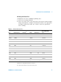
The table below summarizes the 34405A's settings as received from the
factory, following power cycling, and following the *RST command received
over the USB remote interface. Non- volatile, user customizable behavioral
differences are shown in BOLD type.
Table 2
Reset/Power-On State
Parameter
Factory Setting
Power-on / Reset State
Function
DCV
DCV
Range
AUTO
AUTO
Resolution
5-½ digits
5-½ digits
Temperature Units
°C
User setting
Math State, Function
Off, Null
Off, Null
Math Registers
Cleared
Cleared
dBm Reference Resistance
600Ω
User setting
Math Register Editing
On
User setting
Auto Trigger (Local Mode)
IMMediate (Remote Mode)
Auto Trigger (Local Mode)
IMMediate (Remote Mode)
Power-Down Recall
Disabled
User Setting
Stored States
0-4 cleared
No Change
Beeper
On
User Setting
Display
On
On
Remote/ Local State*
Local
Local
Keyboard*
Unlocked, Local key enabled
Unlocked, Local key enabled
Measurement Configuration
Math Operations
Trigger Operations
Trigger Source*
System-Related Operations
34405A User’s and Service Guide
43
2
Features and Functions
Table 2
Reset/Power-On State
Parameter
Factory Setting
Power-on / Reset State
Reading Output Buffer*
Cleared
Cleared
Error Queue*
Cleared
Cleared
Power-on Status Clear*
Last
User Setting
Status Registers, Masks & Transition
Filters*
Cleared
Cleared if power-on status clear
enabled; no change otherwise
Serial Number
Unique value per-instrument
No Change
Calibration state
Secured
User Setting
Calibration value
0
No Change
Calibration String
Cleared
No Change
Calibration
*State managed by IO Processor firmware.
44
34405A User’s and Service Guide
Features and Functions
2
Triggering the Multimeter
From the front panel (Local mode), the multimeter always auto–triggers.
Auto triggering takes continuous readings at the fastest rate possible for
the selected measurement configuration.
From the remote interface, triggering the multimeter is a three–step
process:
1 Configure the multimeter for the measurement by selecting the
function, range, resolution, and so on.
2 Specify the multimeter’s trigger source. Choices are a software (bus)
trigger from the remote interface or an immediate internal trigger
(default trigger source).
3 Ensure that the multimeter is ready to accept a trigger from the
specified source (called the wait–for–trigger state).
Immediate Triggering
The immediate triggering mode is available from the remote interface only.
In the immediate trigger mode, the trigger signal is always present. When
you place the multimeter in the wait–for–trigger state, the trigger is issued
immediately. This is the default trigger source for remote interface
operation.
• Remote Interface Operation: The following command selects the immediate
trigger source:
TRIGger:SOURce IMMediate
The CONFigure and MEASure? commands automatically set the trigger
source to IMMediate.
Refer to the Agilent 34405A Programmer’s Reference for complete
description and syntax for these commands.
Software (Bus) Triggering
The bus trigger mode is available from the remote interface only.
The bus trigger mode is initiated by sending a bus trigger command, after
selecting BUS as the trigger source.
• The TRIGger:SOURce BUS command selects the bus trigger source.
34405A User’s and Service Guide
45
2
Features and Functions
• The MEASure? command overwrites the BUS trigger and triggers the
DMM and returns a measurement.
• The READ? command does not overwrite the BUS trigger, and if
selected, generates an error. It will only trigger the instrument and
return a measurement when the IMMEdiate trigger is selected.
• The INITiate command only initiates the measurement and needs a
trigger (BUS or IMMEdiate) to make the actual measurement.
Refer to the Agilent 34405A Programmer’s Reference for complete
description and syntax for these commands.
46
34405A User’s and Service Guide
Agilent 34405A 5 ½ Digit Multimeter
User’s and Service Guide
3
Measurement Tutorial
DC Measurement Considerations 48
Noise Rejection 49
Resistance Measurement Considerations 51
True RMS AC Measurements 53
Other Primary Measurement Functions 56
Other Sources of Measurement Error 59
The Agilent 34405A multimeter is capable of making very
accurate measurements. In order to achieve the greatest
accuracy, you must take the necessary steps to eliminate
potential measurement errors. This chapter describes
common errors found in measurements and gives suggestions
to help you avoid these errors.
Agilent Technologies
47
3
Measurement Tutorial
DC Measurement Considerations
Thermal EMF Errors
Thermoelectric voltages are the most common source of error in low–level
DC voltage measurements. Thermoelectric voltages are generated when you
make circuit connections using dissimilar metals at different temperatures.
Each metal–to–metal junction forms a thermocouple, which generates a
voltage proportional to the junction temperature. You should take the
necessary precautions to minimize thermocouple voltages and temperature
variations in low–level voltage measurements. The best connections are
formed using copper–to–copper crimped connections, as the multimeter’s
input terminals are a copper alloy. The table below shows common
thermoelectric voltages for connections between dissimilar metals.
Copper to –
Cadmium-Tin Solder
Copper
Gold
Silver
Brass
Beryllium Copper
48
Approx. mV / °C
0.2
<0.3
0.5
0.5
3
5
Copper to –
Aluminum
Tin-Lead Solder
Kovar or Alloy 42
Silicon
Copper-Oxide
Approx. mV / °C
5
5
40
500
1000
34405A User’s and Service Guide
Measurement Tutorial
3
Noise Rejection
Rejecting Power–Line Noise Voltages
A desirable characteristic of integrating analog–to–digital (A/D) converters
is their ability to reject power–line related noise present with DC input
signals. This is called normal mode noise rejection, or NMR. The
multimeter achieves NMR by measuring the average DC input by
"integrating" it over a fixed period.
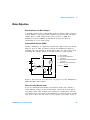
Common Mode Rejection (CMR)
Ideally, a multimeter is completely isolated from earth–referenced circuits.
However, there is finite resistance between the multimeter's input LO
terminal and earth ground, as shown below. This can cause errors when
measuring low voltages which are floating relative to earth ground.
HI
Ideal
Meter
Vtest
Vf = Float Voltage
Rs = DUT Source Resistance
Imbalance
Ri = Multimeter Isolation Resistance
(LO-Earth)
Ci = Multimeter Input Capacitance:
Rs
Error (v) =
LO
Vf
Ci
Vf x Rs
Rs + Ri
Ri
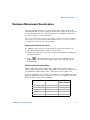
Refer to “Measurement Noise Rejection” on page 131 for the multimeter’s
NMR and CMR characteristics.
Noise Caused by Magnetic Loops
If you are making measurements near magnetic fields, take caution to
avoid inducing voltages in the measurement connections. You should be
especially careful when working near conductors carrying large currents.
Use twisted–pair connections to the multimeter to reduce the noise pickup
loop area, or dress the test leads as close together as possible. Loose or
34405A User’s and Service Guide
49
3
Measurement Tutorial
vibrating test leads will also induce error voltages. Tie down test leads
securely when operating near magnetic fields. Whenever possible, utilize
magnetic shielding materials or increased distance from magnetic sources.
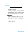
Noise Caused by Ground Loops
When measuring voltages in circuits where the multimeter and the device
under test are both referenced to a common earth ground, a ground loop
is formed. As shown below, any voltage difference between the two ground
reference points (Vground) causes a current to flow through the
measurement leads. This causes noise and offset voltage (usually
power–line related), which are added to the measured voltage.
RL
HI
Ideal
Meter
Vtest
RL
LO
Ri > 10 GΩ
Vground
RL = Lead Resistance
Ri = Multimeter Isolation Resistance
Vground = Voltage Drop on Ground Bus
The best way to eliminate ground loops is to isolate the multimeter from
earth by not grounding the input terminals. If the multimeter must be
earth–referenced, connect it and the device under test to the same
common ground point. Also connect the multimeter and device under test
to the same electrical outlet whenever possible.
50
34405A User’s and Service Guide
Measurement Tutorial
3
Resistance Measurement Considerations
When measuring resistance, the test current flows from the input HI
terminal through the resistor being measured. The voltage drop across the
resistor being measured is sensed internal to the multimeter. Therefore,
test lead resistance is also measured.
The errors mentioned earlier in this chapter for DC voltage measurements
also apply to resistance measurements. Additional error sources unique to
resistance measurements are discussed here.
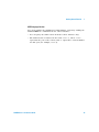
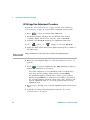
Removing Test Lead Resistance Errors
To eliminate offset errors associated with the test lead resistance in
2–wire ohms measurements, follow the steps below.
1 Connect the ends of the test leads together. The multimeter displays the
test lead resistance.
Null
2 Press
. The multimeter stores the test lead resistance as the
2–wire ohms null value, and subtracts that value from subsequent
measurements.
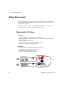
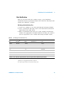
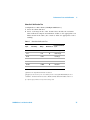
Minimizing Power Dissipation Effects
When measuring resistors designed for temperature measurements (or
other resistive devices with large temperature coefficients), be aware that
the multimeter will dissipate some power in the device under test.
If power dissipation is a problem, you should select the multimeter's next
higher measurement range to reduce the errors to acceptable levels. The
following table shows several examples.
Range
100 Ω
1 kΩ
1 mA
0.83 mA
DUT
Power at Full Scale
100 mW
689 mW
10 kΩ
100 mA
100 mW
100 kΩ
10 mA
10 mW
1 MΩ
34405A User’s and Service Guide
Test Current
900nA
810 nW
51
3
Measurement Tutorial
10 MΩ
205 nA
420 nW
100 MΩ
205 nA ||10 MΩ
35 nW
Errors in High Resistance Measurements
When you are measuring large resistances, significant errors can occur
due to insulation resistance and surface cleanliness. You should take the
necessary precautions to maintain a "clean" high–resistance system. Test
leads and fixtures are susceptible to leakage due to moisture absorption in
insulating materials and "dirty" surface films. Nylon and PVC are relatively
poor insulators (109 W) when compared to PTFE insulators
(1013 W). Leakage from nylon or PVC insulators can easily contribute a
0.1% error when measuring a 1 MW resistance in humid conditions.
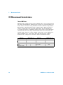
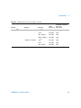
AC Measurements
Each single ACV or ACI measurement is computed based upon a RMS
(root- mean- square) value calculated on an array of 25 sequential A/D
converter samples acquired with constant sample- to- sample timing.
Samples are acquired at a rate very close to the maximum trigger- settle
rate for the A/D converter as shown below.
When configured for an ACV or ACI measurement, the multimeter acquires
an array of 25 sequential samples which comprise the AC reading data
set. The final AC reading result is computed from the acquired data set
as shown by the equation below:
AC Reading = √ Average [Data (1:25)]2
52
34405A User’s and Service Guide
Measurement Tutorial
3
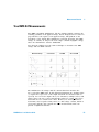
True RMS AC Measurements
True RMS responding multimeters, like the Agilent 34405A, measure the
"heating" potential of an applied voltage. Power dissipated in a resistor is
proportional to the square of an applied voltage, independent of the
waveshape of the signal. This multimeter accurately measures true RMS
voltage or current, as long as the wave shape contains negligible energy
above the instrument’s effective bandwidth.
Note that the 34405A uses the same techniques to measure true RMS
voltage and true RMS current.
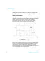
Waveform Shape
Crest Factor
AC RMS
AC + DC RMS
The multimeter's AC voltage and AC current functions measure the
AC–coupled true RMS value. In this Agilent instrument, the “heating value”
of only the AC components of the input waveform are measured (DC is
rejected). As seen in the figure above; for sinewaves, triangle waves, and
square waves, the AC–coupled and AC+DC values are equal, since these
waveforms do not contain a DC offset. However, for non–symmetrical
waveforms, such as pulse trains, there is a DC voltage content, which is
rejected by Agilent’s AC–coupled true RMS measurements. This can
provide a significant benefit.
34405A User’s and Service Guide
53
3
Measurement Tutorial
An AC–coupled true RMS measurement is desirable when you are
measuring small AC signals in the presence of large DC offsets. For
example, this situation is common when measuring AC ripple present on
DC power supplies. There are situations, however, where you might want
to know the AC+DC true RMS value. You can determine this value by
combining results from DC and AC measurements, as shown below:
For the best AC noise rejection, you should perform the DC measurement
at 5½- digits.
True RMS Accuracy and High–Frequency Signal Content
A common misconception is that "since an AC multimeter is true RMS, its
sine wave accuracy specifications apply to all waveforms." Actually, the
shape of the input signal can dramatically affect measurement accuracy,
for any multimeter, especially when that input signal contains
high–frequency components which exceed the instrument’s bandwidth.
Error in RMS measurements arise when there is significant input signal
energy at frequencies above the multimeter’s bandwidth.
Estimating High–Frequency (Out–of–Band) Error
A common way to describe signal waveshapes is to refer to their “Crest
Factor”. Crest factor is the ratio of the peak value to RMS value of a
waveform. For a pulse train, for example, the crest factor is approximately
equal to the square root of the inverse of the duty cycle.
Notice that crest factor is a composite parameter, dependent upon the
pulse–width and repetition frequency; crest factor alone is not enough to
characterize the frequency content of a signal.
Traditionally, DMMs include a crest factor derating table that applies at all
frequencies. The measurement algorithm used in the 34405A multimeter is
not inherently sensitive to crest factor, so no such derating is necessary.
54
34405A User’s and Service Guide
Measurement Tutorial
3
With this multimeter, as discussed in the previous section, the focal issue
is high–frequency signal content which exceeds the multimeter’s
bandwidth.
For periodic signals, the combination of crest factor and repetition rate
can suggest the amount of high–frequency content and associated
measurement error. The first zero crossing of a simple pulse occurs at
f1 =
1
tp
This gives an immediate impression of the high- frequency content by
identifying where this crossing occurs as a function of crest
factor: f = CF 2 ⋅ prf
1
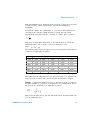
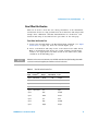
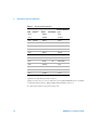
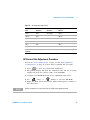
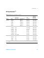
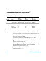
The following table shows the typical error for various pulse waveforms as
a function of input pulse frequency:
prf
200
1000
2000
5000
10000
20000
50000
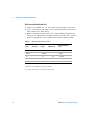
100000
Typical error for square wave, triangular wave, and pulse trains of CF=3, 5, or 10
square wave triangle wave
CF=3
CF=5
CF=10
–0.02%
0.00%
–0.04%
–0.09%
–0.34%
–0.07%
0.00%
–0.18%
–0.44%
–1.71%
–0.14%
0.00%
–0.34%
–0.88%
–3.52%
–0.34%
0.00%
–0.84%
–2.29%
–8.34%
–0.68%
0.00%
–1.75%
–4.94%
–26.00%
–1.28%
0.00%
–3.07%
–8.20%
–45.70%
–3.41%
–0.04%
–6.75%
–32.0%
–65.30%
–5.10%
–0.12%
–21.8%
–50.6%
–75.40%
This table gives an additional error for each waveform, to be added to the
value from the accuracy table provided in the Specifications chapter.
Example: A pulse train with level 1 Vrms, is measured on the 1 V range. It
has pulse heights of 3 V (that is, a Crest Factor of 3) and duration 111 ms.
The prf can be calculated to be 1000 Hz, as follows:
Thus, from the table above, this AC waveform can be measured with 0.18
percent additional error.
34405A User’s and Service Guide
55
3
Measurement Tutorial
Other Primary Measurement Functions
Frequency Measurement Errors
The multimeter uses a reciprocal counting technique to measure
frequency. This method generates constant measurement resolution for any
input frequency. All frequency counters are susceptible to errors when
measuring low–voltage, low–frequency signals. The effects of both internal
noise and external noise pickup are critical when measuring "slow" signals.
The error is inversely proportional to frequency. Measurement errors also
occur if you attempt to measure the frequency of an input following a DC
offset voltage change. You must allow the multimeter's input to fully settle
before making frequency measurements.
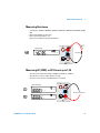
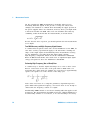
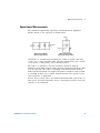
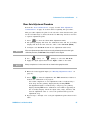
DC Current Measurements
When you connect the multimeter in series with a test circuit to measure
current, a measurement error is introduced. The error is caused by the
multimeter's series burden voltage. A voltage is developed across the
wiring resistance and current shunt resistance of the multimeter, as
shown below.
Rs
Vs
I
R
Vb
Ideal
Meter
LO
Vs = Source Voltage
Rs = DUT Source Resistance
Vb = Multimeter Burden Voltage
R = Multimeter Current Shunt
56
Error (%) =
-100% x Vb
Vs
34405A User’s and Service Guide
Measurement Tutorial
3
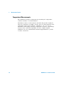
Capacitance Measurements
The multimeter implements capacitance measurements by applying a
known current to the capacitor as shown below:
Coffset
C
RP
Coffset
Vcharge
C
R'
d
Measurement Model
(during charge phase)
Measurement Model
(during discharge phase)
Capacitance is calculated by measuring the change in voltage (DV) that
occurs over a “short aperture” time, (Dt). The measurement cycle consists
of two parts: a charge phase and a discharge phase.
The values of capacitance and loss resistance measured with the
multimeter may differ from the values measured using an LCR meter. This
is to be expected, since this is essentially a DC measurement method,
while LCR measurement uses applied frequencies anywhere from 100 Hz
to 100 kHz. In most cases, neither method measures the capacitor at its
exact frequency of application.
For the best accuracy, take a zero null measurement with open probes, to
null out the test lead capacitance, before connecting the probes across the
capacitor to be measured.
34405A User’s and Service Guide
57
3
Measurement Tutorial
Temperature Measurements
The multimeter measures temperature by measuring the temperature
sensitive resistance of 5 kW thermistors.
Thermistors consist of semiconductor materials and provide roughly 10
times the sensitivity of an RTD. Because they are semiconductors, their
temperature range is more limited, commonly to –80 oC to 150 oC.
Thermistors have highly non–linear temperature–resistance relationships;
therefore their conversion algorithms are more complex. Agilent
multimeters use the standard Hart–Steinhart Approximation to provide
accurate conversions.
58
34405A User’s and Service Guide
Measurement Tutorial
3
Other Sources of Measurement Error
Loading Errors (AC volts)
In the AC voltage function, the input of the multimeter appears as a 1 MW
resistance in parallel with 100 pF of capacitance. The cabling that you use
to connect signals to the multimeter also adds capacitance and loading.
For low frequencies, the loading error is:
Error (%) =
-100 x Rs
Rs + 1 MΩ
At high frequencies, the additional loading error is:
Error (%) =
Rs = Source Resistance
F = Input Frequency
Cin = Input Capacitance (100 pF) Plus Cable
Capacitance
Measurements Below Full Scale
You can make the most accurate AC measurements when the multimeter is
at or near the full scale of the selected range. Autoranging occurs at 10%
(down–range) and 120% (up–range) of full scale. This enables you to
measure some inputs at full scale on one range and 10% of full scale on
the next higher range. In general, the accuracy is better on the lower
range; for the highest accuracy, select the lowest manual range possible for
the measurement.
High–Voltage Self–Heating Errors
If you apply more than 300 Vrms, self–heating occurs in the multimeter's
internal signal–conditioning components. These errors are included in the
multimeter's specifications.
Temperature changes inside the multimeter due to self–heating may cause
additional error on other AC voltage ranges.
34405A User’s and Service Guide
59
3
Measurement Tutorial
AC Current Measurement Errors (Burden Voltage)
Burden voltage errors, which apply to DC current, also apply to AC
current measurements. However, the burden voltage for AC current is
larger due to the multimeter's series inductance and your measurement
connections. The burden voltage increases as the input frequency
increases. Some circuits may oscillate when performing current
measurements due to the multimeter's series inductance and your
measurement connections.
Low–Level Measurement Errors
When measuring AC voltages less than 100 mV, be aware that these
measurements are especially susceptible to errors introduced by
extraneous noise sources. An exposed test lead acts as an antenna and a
properly functioning multimeter will measure the signals received. The
entire measurement path, including the power line, acts as a loop antenna.
Circulating currents in the loop create error voltages across any
impedances in series with the multimeter's input. For this reason, you
should apply low–level AC voltages to the multimeter through shielded
cables. You should connect the shield to the input LO terminal.
Make sure the multimeter and the AC source are connected to the same
electrical outlet whenever possible. You should also minimize the area of
any ground loops that cannot be avoided. A high–impedance source is
more susceptible to noise pickup than a low–impedance source. You can
reduce the high–frequency impedance of a source by placing a capacitor in
parallel with the multimeter's input terminals. You may have to
experiment to determine the correct capacitor value for your application.
Most extraneous noise is not correlated with the input signal. You can
determine the error as shown below.
Voltage Measured =
Vin2 + Noise2
Correlated noise, while rare, is especially detrimental. Correlated noise
always adds directly to the input signal. Measuring a low–level signal with
the same frequency as the local power line is a common situation that is
prone to this error.
60
34405A User’s and Service Guide
Measurement Tutorial
3
Pulse Measurement Error
You can use the DC measurement function to measure a pulse signal and
obtain its relevant average measurement quickly. The formula of the
equivalent DC average of a pulse signal is provided below.
--1- f ( x ) dx
T
∫
T
where f(x) is the function representing the signal waveform over a period
of T.
Error may occur when the pulse signal is measured at low voltage range
due to saturation of the multimeter’s analog- to- digital (ADC) rail voltage.
34405A User’s and Service Guide
61
3
Measurement Tutorial
THIS PAGE HAS BEEN INTENTIONALLY LEFT BLANK.
62
34405A User’s and Service Guide
Agilent 34405A 5 ½ Digit Multimeter
User’s and Service Guide
4
Performance Tests and Calibration
Calibration Overview 64
Recommended Test Equipment 66
Test Considerations 67
Performance Verification Tests Overview 68
Performance Verification Tests 70
Calibration Security 82
Calibration Process 85
Adjustments 88
Calibration Errors 103
This chapter contains performance test procedures and
calibration procedures. The performance tests procedures
allow you to verify that the multimeter is operating within
its published specifications.
The calibration procedures show how to make zero and gain
adjustments to the multimeter.
WA R N I N G
SHOCK HAZARD. Only service–trained personnel who are aware of the hazards
involved should perform the procedures in this chapter. To avoid electrical shock and
personal injury, make sure to read and follow all test equipment safey instructions.
Use only completely electrically insulated test lead sets with connectors that
prevent contact with test voltages.
Agilent Technologies
63
4
Performance Tests and Calibration
Calibration Overview
NOTE
Make sure you have read “Test Considerations” on page 67 before calibrating the
instrument.
Closed - Case Electronic Calibration
The instruments features closed- case electronic calibration. No internal
mechanical adjustments are required. The instrument calculates correction
factors based upon the input reference value you set. The new correction
factors are stored in non- volatile memory until the next calibration
adjustment is performed. Non - volatile EEPROM calibration memory does
not change when power has been off or after a remote interface reset
Agilent Technologies Calibration Services
When your instrument is due for calibration, contact your local Agilent
Service Center for a low- cost recalibration. The 34405A is supported on
automated calibration systems, which allow Agilent to provide this service
at competitive prices.
Calibration Interval
A 1- year interval is adequate for most applications. Accuracy
specifications are warranted only if adjustment is made at regular
calibration intervals. Accuracy specifications are not warranted beyond the
1- year calibration interval. Agilent does not recommend extending
calibration intervals beyond 2 years for any application.
64
34405A User’s and Service Guide
Performance Tests and Calibration
4
Time Required for Calibration
The 34405A can be automatically calibrated under computer control. With
computer control you can perform the complete calibration procedure and
performance verification tests in less than 30 minutes once the instrument
is warmed- up (see “Test Considerations” on page 67). Refer to the 34405A
Programmer’s Reference online help for more information.
34405A User’s and Service Guide
65
4
Performance Tests and Calibration
Recommended Test Equipment
The test equipment recommended for the performance verification and
adjustment procedures is listed below.If the exact instrument is not
available, substitute calibration standards of equivalent accuracy.
A suggested alternate method would be to use the Agilent 3458A 8½
- Digit Digital Multimeter to measure less accurate yet stable sources. The
output value measured from the source can be entered into the instrument
as the target calibration value.
Table 3
Recommended Test Equipment
Application
Recommended Equipment
Recommended Accuracy Requirements
Zero Calibration
Shorting Plug--Dual banana plug with copper wire
short between the two terminals
DC Voltage
Fluke 5520A
<1/5 instrument 1 year spec
DC Current
Fluke 5520A
<1/5 instrument 1 year spec
Resistance
Fluke 5520A
<1/5 instrument 1 year spec
AC Voltage
Fluke 5520A
<1/5 instrument 1 year spec
AC Current
Fluke 5520A
<1/5 instrument 1 year spec
Frequency
Fluke 5520A
<1/5 instrument 1 year spec
Capacitance
Fluke 5520A
<1/5 instrument 1 year spec
66
34405A User’s and Service Guide
Performance Tests and Calibration
4
Test Considerations
Errors may be induced by AC signals present on the input leads during a
self- test. Long test leads can also act as an antenna causing pick- up of AC
signals.
For optimum performance, all procedures should comply with the
following recommendations:
• Assure that the calibration ambient temperature is stable and between
18 °C and 28 °C. Ideally the calibration should be performed at 23 °C
±1 °C.
• Assure ambient relative humidity is less than 80%.
• Allow a 1- hour warm- up period with a Shorting Plug connected to the
HI and LO input terminals.
• Use shielded twisted pair PTFE- insulated cables to reduce settling and
noise errors. Keep the input cables as short as possible.
• Connect the input cable shields to earth ground. Except where noted in
the procedures, connect the calibrator LO source to earth ground at the
calibrator. It is important that the LO to earth ground connection be
made at only one place in the circuit to avoid ground loops.
Because the instrument is capable of making very accurate measurements,
you must take special care to ensure that the calibration standards and
test procedures used do not introduce additional errors. Ideally, the
standards used to verify and adjust the instrument should be an order of
magnitude more accurate than each instrument range full- scale error
specification.
Input Connections
Test connections to the instrument are best accomplished using the dual
banana plug with copper wire short between two terminals for
low- thermal offset measurement. Shielded, twisted- pair, PTFE interconnect
cables of minimum length are recommended between the calibrator and
the multimeter. Cable shields should be earth ground referenced. This
configuration is recommended for optimal noises and settling time
performance during calibration.
34405A User’s and Service Guide
67
4
Performance Tests and Calibration
Performance Verification Tests Overview
Use the Performance Verification Tests to verify the measurement
performance of the instrument. The performance verification tests use the
instrument's specifications listed in Chapter 6, “Specifications”.
You can perform four different levels of performance verification tests:
Self- Test A series of internal verification tests that give a high confidence
that the instrument is operational.
Quick Verification A combination of the internal self- tests and selected
verification test.
Performance Verification Tests An extensive set of tests that are
recommended as an acceptance test when you first receive the instrument
or after performing adjustments.
Optional Verification Tests Tests not performed with every calibration.
Perform these tests to verify additional specifications or functions of the
instrument.
Self -Test
• A brief power- on self- test occurs automatically whenever you turn on
the instrument. This limited test assures that the instrument is capable
of operation.
• During the self- test all display segments and annunciators are lit.
• If the self- test fails, an error is reported on the front panel. You can
also use the SYSTem: ERRor? command query from the remote
interface. If repair is required, contact an Agilent Service Center.
• If all tests pass, you have a high confidence (~90%) that the instrument
is operational.
• You can initiate a more complete self- test by sending the *TST?
command to the instrument. This command returns a "+0" if all the
self- tests pass, or a "+1" if a failure occurred. This command may take
up to 30 seconds to complete. You may need to set an appropriate
interface time- out value.
68
34405A User’s and Service Guide
Performance Tests and Calibration
4
Quick Performance Check
The quick performance check is a combination of internal self- test and an
abbreviated performance test (specified by the letter Q in the performance
verification tests). This test provides a simple method to achieve high
confidence in the instrument's ability to functionally operate and meet
specifications. These tests represent the absolute minimum set of
performance checks recommended following any service activity. Auditing
the instrument's performance for the quick check points (designated by a
Q) verifies performance for "normal" accuracy drift mechanisms. This test
does not check for abnormal component failures.
To perform the quick performance check, do the following:
• Perform a self- test as described in the preceding section.
• Perform only the performance verification tests indicated in the
following tables with the letter Q.
If the instrument fails the quick performance check, adjustment or repair
is required
34405A User’s and Service Guide
69
4
Performance Tests and Calibration
Performance Verification Tests
The performance verification tests are recommended as acceptance tests
when you first receive the instrument. The acceptance test results should
be compared against the 1- year test limits. After acceptance, you should
repeat the performance verification tests at every calibration interval.
If the instrument fails performance verification, adjustment or repair is
required.
Adjustment is recommended at every calibration interval. If adjustment is
not made, you must establish a 'guard band', using no more than 80% of
the specifications, as the verification limits.
NOTE
70
Make sure you have read “Test Considerations” on page 67 before doing the performance
verification tests.
34405A User’s and Service Guide
Performance Tests and Calibration
4
Zero Offset Verification
This test is used to check the zero offset performance of the instrument.
Verification checks are only performed for those functions and ranges with
unique offset calibration constants. Measurements are checked for each
function and range as described in the procedure on the next page.
Zero Offset Verification Test
1 Connect the Shorting Plug to the HI and LO input terminals. (see “Input
Connections” on page 67). Leave the current inputs open.
2 Select each function and range in the order shown in the table below.
Make a measurement and observe the result. Compare measurement
results to the appropriate test limits shown in the table below (table
continued on thefollowing page).
NOTE
Note that resistance measurements use the Null math function (Null reading taken with
test leads connected together) to eliminate test lead resistance.
Table 4
Input
Open
Zero Offset Verification Test
Function[1]
Range
DC Current
10mA
Error from Nominal
Quick Check 1 year
Q
±1.5µA
Open
100mA
±5 µA
Open
1A
±70µA
Open
10A
±0.7mA
1nF
±8pF
Open
10nF
±0.05nF
Open
100nF
±0.5nF
Open
1µF
±5nF
Open
10µF
±0.05µF
Open
100µF
±0.5µF
Open
Capacitance
34405A User’s and Service Guide
71
4
Performance Tests and Calibration
Table 4
Input
Zero Offset Verification Test
Function[1]
Range
Error from Nominal
Quick Check 1 year
Open
1000µF
±5µF
Open
10000µF
±0.05mF
100mV
±8 µV
Short
DC Volts
Short
1V
Short
10 V
±0.5 mV
Short
100 V
±5 mV
Short
1000 V
±50 mV
100 Ω
±8 mΩ [2]
Short
1 kΩ
±50 mΩ [2]
Short
10 kΩ
Short
100 kΩ
±7 Ω
Short
1 MΩ
±70 Ω
Short
10 MΩ
±500 Ω
Short
100 MΩ
±5 kΩ
Short
2-Wire Ohms
Q
Q
±60 µV
±600 mΩ [2]
[1] Select 5½- digit measurement resolution
[2] Specifications are for 2- wire ohms function using the Null math function enabled
to eliminate lead resistance. Without Null, add 0.2 Ω additional error.
Q = Quick performance verification test points
72
34405A User’s and Service Guide
Performance Tests and Calibration
4
Gain Verification
This test checks the full- scale reading accuracy of the instrument.
Verification checks are performed only for those functions and ranges with
unique gain calibration constants.
DC Voltage Gain Verification Test
1 Connect the calibrator to the front panel HI and LO input terminals.
2 Select each function and range in the order shown below. Provide the
input shown in the table below.
3 Make a measurement and observe the result. Compare measurement
results to the appropriate test limits shown in the table. (Be certain to
allow for appropriate source settling when using the Fluke 5520A.)
Table 5
Input
100mV
DC Voltage Gain Verification Test
Function[1]
DC Volts
Range
Quick Check
Error from Nominal
1 year
100mV
±33 µV
-100mV
100mV
±33 µV
1V
1V
-1V
1V
±0.31 mV
10V
10 V
±3.0 mV
100V
100 V
1000V
1000 V
Q
Q
±0.31 mV
±30 mV
±0.3 V
Caution: Set the calibrator output to 0V before disconnecting it from the multimeter input terminals.
[1] Select 5½- digit measurement resolution
Q = Quick performance verification test points
34405A User’s and Service Guide
73
4
Performance Tests and Calibration
DC Current Gain Verification Test
1 Connect the calibrator to the front panel I and LO input connectors.
2 Select each function and range in the order shown below. Provide the
input shown in the table below.
3 Make a measurement and observe the result. Compare measurement
results to the appropriate test limits shown in the table. (Be certain to
allow for appropriate source settling when using the Fluke 5520A.)
Table 6
DC Current Gain Verification Test
Input
Function[1]
10mA
DC Current
Range
Quick Check
10 mA
100mA
100 mA
1A
1A
Q
Error from Nominal
1 year
± 6.5µA
± 55µA
Q
± 2.07mA
Caution: Connect calibrator to multimeter’s 12A and LO terminals before applying 10A
10A
10 A
± 25.7mA
[1] Select 5½- digit measurement resolution
Q = Quick performance verification test points
74
34405A User’s and Service Guide
Performance Tests and Calibration
4
Ohms Gain Verification Test
Configuration: 2- Wire Ohms (CONFigure:RESistance)
1 Select the Ohms function.
2 Select each range in the order shown below. Provide the resistance
value indicated. Compare measurement results to the appropriate test
limits shown in the table. (Be certain to allow for appropriate source
settling.)
Table 7
Ohms Gain Verification Test
Input
Function[1]
100 Ω
2-Wire Ohms
Range
Error from Nominal
Quick Check 1 year
100 Ω
±58 mΩ [2]
1 kΩ
1 kΩ
Q
10 kΩ
10 kΩ
±5.6 Ω [2]
100 kΩ
100 kΩ
±57 Ω
1 MΩ
1 MΩ
±670 Ω
10 MΩ
10 MΩ
100 MΩ
100 MΩ
Q
±550 mΩ [2]
±25.5 kΩ
±2.005MΩ
[1] Select 5½- digit measurement resolution
[[2] Specifications are for 2- wire ohms function using the Null math function
enabled to eliminate lead resistance. Without Null, add 0.2 Ω additional error.
Q = Quick performance verification test points
34405A User’s and Service Guide
75
4
Performance Tests and Calibration
Frequency Gain Verification Test
Configuration: Frequency (CONFigure:FREQuency)
1 Select the Frequency function.
2 Select each range in the order shown below. Provide the input voltage
and frequency indicated. Compare measurement results to the
appropriate test limits shown in the table. (Be certain to allow for
appropriate source settling.)
Table 8
Voltage
Frequency Gain Verification Test
Input
Frequency Function[1]
200mVrms
1kHz
200mVrms
10kHz
Frequency
Range
Error from Nominal
Quick Check 1 year
1V
1V
Q
±0.23Hz
±2.3Hz
[1] Select 5½- digit measurement resolution
Q = Quick performance verification test points
76
34405A User’s and Service Guide
Performance Tests and Calibration
4
AC Voltage Verification Test
Configuration: AC Volts (CONFigure[:VOLTage]:AC)
1 Select the AC Voltage function.
2 Select each range in the order shown below. Provide the indicated input
voltage and frequency. Compare measurement results to the appropriate
test limits shown in the table. (Be certain to allow for appropriate
source settling.)
Table 9
Vrms
AC Volts Verification Test
Input Frequency
100mV
1kHz
100mV
Function[1]
AC Voltage
Range
Quick Check
Error from Nominal
1 year
100mV
± 0.3 mV
30kHz
100mV
± 1.8 mV
100mV
100kHz
100mV
± 5.3 mV
1V
1kHz
1V
1V
30kHz
1V
± 11 mV
1V
100kHz
1V
± 32 mV
10V
45Hz
10V
± 110 mV
10V
1kHz
10V
± 30 mV
10V
30kHz
10V
10V
100kHz
10V
100V
1kHz
100V
100V
30kHz
100V
± 1.1 V
100V
100kHz
100V
± 3.2 V
750V
1kHz
750V
± 2.25 V
Q
Q
± 3.0 mV
± 0.11 V
± 0.32 V
Q
± 0.3 V
Caution: Set the calibrator output to 0V before disconnecting it from the multimeter input terminals.
[1] Select 5½- digit measurement resolution
Q = Quick performance verification test points
34405A User’s and Service Guide
77
4
Performance Tests and Calibration
AC Current Verification Test
Configuration: AC Current (CONFigure:CURRent:AC)
1 Select the AC Current function.
2 Select each range in the order shown below. Provide the input current
and frequency indicated. Compare measurement results to the
appropriate test limits shown in the table. (Be certain to allow for
appropriate source settling.)
Table 10
Current
AC Current Verification Test
Input Frequency
Function[1]
AC Current
Range
10 mA
Quick Check
Q
Error from Nominal
1 year
10 mA
1 kHz
± 60 µA
10 mA
10 kHz
10 mA
± 220 µA
100 mA
1 kHz
100 mA
± 600 µA
100 mA
10 kHz
100 mA
± 2.2 mA
1A
1 kHz
1A
± 6 mA
1A
5 kHz
1A
± 22 mA
Caution: Connect calibrator to multimeter’s 12A and LO terminals before applying 10A
10 A
1 kHz
10 A
± 60 mA
2A
5 kHz
10 A
± 0.06 A
[1] Select 5½- digit measurement resolution
Q = Quick performance verification test points
78
34405A User’s and Service Guide
Performance Tests and Calibration
4
Optional AC Voltage Performance Verification Test
Configuration: AC Volts (CONFigure[:VOLTage]:AC)
1 Select the AC Voltage function.
2 Select each range in the order shown below. Provide the indicated input
voltage and frequency. Compare measurement results to the appropriate
test limits shown in the table. (Be certain to allow for appropriate
source settling.)
Table 11
Vrms
Optional AC Voltage Performance Verification Test
Input Frequency Function[1]
1V
45Hz
1V
AC Voltage
Error from Nominal
Range 1 year
1V
±11mV
1kHz
1V
±3mV
1V
10kHz
1V
±3mV
1V
30kHz
1V
±11mV
1V
100kHz
1V
±32mV
10V
1kHz
10V
±30mV
1V
1kHz
10V
±12mV
0.1V
1kHz
10V
±10.2mV
[1] Select 5½- digit measurement resolution
34405A User’s and Service Guide
79
4
Performance Tests and Calibration
Optional AC Current Performance Verification Test
Configuration: AC Current (CONFigure:CURRent:AC)
1 Select the AC Current function.
2 Select each range in the order shown below. Provide the indicated input
voltage and frequency. Compare measurement results to the appropriate
test limits shown in the table. (Be certain to allow for appropriate
source settling.)
Table 12
Current
Optional AC Current Performance Verification Test
Input Frequency Function[1]
10mA
20Hz
10mA
AC Current
Range
Error from Nominal
1 year
10mA
± 0.16mA
45Hz
10mA
± 0.16mA
10mA
1kHz
10mA
± 60µA
10mA
10kHz
10mA
± 0.22mA
1A
1kHz
1A
± 6mA
100mA
1kHz
1A
± 1.5mA
10mA
1kHz
1A
± 1.05mA
[1] Select 5½- digit measurement resolution
80
34405A User’s and Service Guide
Performance Tests and Calibration
4
Optional Capacitance Performance Verification Test
Configuration: Capacitance (CONFigure:CAPacitance)
1 Select the Capacitance function.
2 Select each range in the order shown below. Provide the indicated input
voltage and frequency. Compare measurement results to the appropriate
test limits shown in the table. (Be certain to allow for appropriate
source settling.)
Table 13
Optional Capacitance Performance Verification Test
Input Capacitance Range
Function[1]
Capacitance
Error from Nominal
1 year
1nF
1nF
± 28pF
10nF
10nF
± 0.15nF
100nF
100nF
± 1.5nF
1µF
1µF
± 15nF
10µF
10µF
± 0.15µF
100µF
100µF
± 1.5µF
1000µF
1000µF
± 15µF
10000µF
10000µF
± 0.25mF
[1] For the best accuracy, take a zero null measurement with open test leads, to null
out the test lead capacitance, before connecting the test leads to the calibrator.
34405A User’s and Service Guide
81
4
Performance Tests and Calibration
Calibration Security
The calibration security code prevents accidental or unauthorized
adjustments to the instrument. When you first receive your instrument, it
is secured. Before you can adjust the instrument, you must unsecure it by
entering the correct security code (see “Unsecuring the Instrument for
Calibration” on page 83).
The security code is set to AT34405 when the instrument is shipped from
the factory. The security code is stored in non- volatile memory, and does
not change when power is turned off or after a Factory Reset (*RST
command) or after an Instrument Preset (SYSTem:PRESet command).
NOTE
You can unsecure the instrument from the front panel, but you cannot enter a new security
code or change the security code from the front panel. The security code can only be
changed from the remote interface after the instrument has been unsecured. Refer to the
CAL:SEC:CODE command in the 34405A Programmer's Reference Help File for more details.
The security code may contain up to 12 alphanumeric characters. The first
character must be a letter. The remaining characters can be letters or
numbers. You do not have to use all 12 characters.
82
34405A User’s and Service Guide
Performance Tests and Calibration
4
Unsecuring the Instrument for Calibration
Before you can adjust the instrument, you must unsecure it by entering
the correct security code. The security code is set to AT34405 when the
instrument is shipped from the factory. The security code is stored in
non- volatile memory, and does not change when power has been off or
after a Factory Reset (*RST command).
Unsecuring from the Front Panel
Only five characters (the third through seventh characters) of the security
code are used to unsecure the instrument from the front panel. If there
are letters instead of digits in any of the third through seventh characters,
those letters will be represented as "0" from the front panel.
Example 1
Assume the calibration security code is the factory setting of AT34405.
When unsecuring from the front panel, the code length is five characters
and the first two characters are ignored. In our example, the code now
becomes:
34405
Example 2
Assume the calibration security code was set to AT01A405 from the
remote interface. When unsecuring from the front panel, the first two
characters and any characters after the eighth through twelfth character
are ignored. In our example, the code now becomes:
01A40
From the front panel, any letters (A in this example) are represented by 0.
Use this code to unsecure:
01040
34405A User’s and Service Guide
83
4
Performance Tests and Calibration
Example 3
Assume the calibration security code has been set to ATB1 through remote
interface. The first two characters (AT) are ignored. The B is represented
by a zero. The “1” is still used and trailing zeros fill in the remaining
characters. Use this code to unsecure:
01000
To Unsecure the Instrument from the Front Panel
DCV
Shift
1 Press
and
simultaneously to enter the Calibration
Security Code entry mode.
2 The primary display shows SECur and the secondary display shows _ _
_ _ .
Store
Recall
Recall
Limit
3 Use the editing keys
Edit
to step to each character
in the code.
Use the range keys
Range
to select each character.
Enter
4 Press
Disp
(Enter) when done.
5 If the correct security code was entered, the CAL annunciator
illuminates and the primary display briefly shows PASS.
84
34405A User’s and Service Guide
Performance Tests and Calibration
4
Calibration Process
The following general procedure is the recommended method to complete
a full instrument calibration.
1 Read “Test Considerations” on page 67.
2 Perform the verification tests to characterize the instrument (incoming
data).
3 Unsecure the instrument for calibration (see “Calibration Security” on
page 82). Once unsecured, the instrument will be in Adjustment Mode
as indicated by the illuminated CAL annunciator.
4 Perform the adjustment procedures (see “Adjustments” on page 88).
5 Secure the instrument against calibration.
6 Note the new security code and calibration count in the instrument's
maintenance records.
NOTE
Make sure to quit the Adjustment Mode then turn off the instrument.
34405A User’s and Service Guide
85
4
Performance Tests and Calibration
Using the Front Panel for Adjustments
This section describes the process used to perform adjustments from the
front panel. Refer to the 34405A Programmer's Reference online help for
remote interface commands.
Selecting the Adjustment Mode
Unsecure the instrument see “Unsecuring the Instrument for
Calibration” on page 83. Once unsecured, the display CAL annunciator
illuminates to indicate you are in Adjustment Mode.
Entering Adjustment Values
In the DMM adjustment procedures, to enter an input calibration value
from the front panel:
Use the edit keys
display.
Store
Recall
Recall
Limit
Edit
Use the up
and down
digits 0 through 9.
to select each digit in the Secondary
arrow keys to advance through the
Enter
Press
Disp
when done.
Aborting a Calibration in Progress
Sometimes it may be necessary to abort a calibration after the procedure
has already been initiated. You can abort a calibration at any time by
pressing:
Shift
The calibration will be aborted, the primary display will show FAIL and
Error 705, CAL Aborted will occur.
86
34405A User’s and Service Guide
Performance Tests and Calibration
CAUTION
4
If you abort a calibration in progress when the instrument is attempting
to write new calibration constants to EEPROM, you may lose all
calibration constants for the function. Typically, upon re–applying power,
the instrument will report error 742 through 748 (whichever is applicable).
If this occurs, you should not use the instrument until a complete
re–adjustment has been performed. A list of the possible calibration errors
is given on page 103.
34405A User’s and Service Guide
87
4
Performance Tests and Calibration
Adjustments
You will need a test input cable and connectors set, and a Shorting Plug
to adjust the instrument (see “Input Connections” on page 67).
NOTE
After each adjustment finishes successfully, the primary display briefly shows PASS. If the
calibration fails, the multimeter beeps, the primary display shows FAil and an error number
is shown in the secondary display. Calibration error messages are described on page 103. In
the event of a calibration failure, correct the problem and repeat the procedure.
Zero Adjustment
Each time you perform a zero adjustment, the instrument stores a new set
of offset correction constants for measurement functions and ranges. The
instrument will sequence through all required functions and ranges
automatically and store new zero offset calibration constants.
CAUTION
Never turn off the instrument during Zero Adjustment. This may cause ALL calibration
memory to be lost.
Zero Adjustment Procedure
Be sure to allow the instrument to warm up and stabilize for 2 hours
before performing the adjustments.
1 Follow the steps outlined below. Review “Test Considerations” on
page 67 before beginning this test.
2 After unsecuring the instrument, the instrument goes into the
Adjustment Mode (as indicated by the CAL annunciator) with the
secondary display showing Short. Connect the Shorting Plug (see
page 68) between the HI and LO front panel input terminals. Leave the
current inputs open.
NOTE
88
To minimize thermal effects wait at least 1 minute after connecting the Shorting Plug before
executing the zero adjustment.
34405A User’s and Service Guide
Performance Tests and Calibration
4
dB
Shift
Null
Null
3 Press
, the display CAL annunciator starts flashing to
indicate the calibration is in progress.
4 The display will show the measurement functions and ranges as the
adjustments progress.
• Successful completion of the adjustment is indicated by a short beep
and the primary display briefly showing PASS.
• An adjustment failure is indicated by a long beep, the primary
display showing FAiL and a calibration error number appearing in
the secondary display. Correct the problem and repeat this
procedure.
5 Remove the Shorting Plug from the input terminals.
Hold
6 Press
Shift
Limit
, the display CAL annunciator will start flashing.
7 The display will show the functions as the open input adjustments
progress.
• Successful completion of the adjustment is indicated by a short beep
and the primary display briefly showing PASS.
• An adjustment failure is indicated by a long beep, the primary
display showing FAiL and a calibration error number appearing in
the secondary display. Correct the problem and repeat this
procedure.
8 Perform the “Zero Offset Verification” on page 71 to check zero
calibration results.
Gain Adjustments
The instrument calculates and stores gain corrections for each input value.
The gain constant is computed from the calibration value entered for the
calibration command and from measurements made automatically during
the adjustment procedure.
Most measuring functions and ranges have gain adjustment procedures.
The 100 MΩ range does not have gain calibration procedures.
Adjustments for each function should be performed ONLY in the order
shown.
34405A User’s and Service Guide
89
4
Performance Tests and Calibration
Gain Adjustment Considerations
• The zero adjustment procedure must have been recently performed
prior to beginning any gain adjustment procedures.
• Be sure to allow the instrument to warm up and stabilize for 2 hours
before performing the adjustments.
• Consider the thermal effects as you are connecting test leads to the
calibrator and multimeter. It is recommended to wait one minute before
starting the calibration after connecting the test leads.
CAUTION
Never turn off the instrument during a Gain Adjustment. This may cause calibration
memory for the present function to be lost.
Valid Gain Adjustment Input Values
Gain adjustment can be accomplished
using the following input values.
Table 14
90
Valid Gain Adjustment Input Values
Function
Range
Valid Amplitude Input Values
DC Volts
100 mV, 1 V, 10 V, 100 V, 1000 V
0.9 to 1.1 x Full Scale
DC Current
10 mA, 100 mA, 1000 mA, 10 A
0.9 to 1.1 x Full Scale
Ohms
100 Ω, 1 kΩ, 10 kΩ, 100 kΩ, 1MΩ, 10 M
Ω
0.9 to 1.1 x Full Scale
Frequency
Autorange/1 kHz
Input ≥ 100 mV rms, 900 Hz to 1100 Hz
AC Current
1 mA, 10 mA, 100 mA, 1000 mA, 10 A
0.9 to 1.1 x Full Scale
AC Volts
10 mV, 100 mV, 1 V, 10 V, 100 V, 750 V
0.9 to 1.1 x Full Scale
Capacitance
0.4 nF, 1 nF, 10 nF, 100 nF, 1 µF, 10 µF,
100 µF, 1000 µF, 10000 µF
0.9 to 1.1 x Full Scale
34405A User’s and Service Guide
Performance Tests and Calibration
4
DC Voltage Gain Adjustment Procedure
Review the “Test Considerations” on page 67 and “Gain Adjustment
Considerations” on page 90 sections before beginning this procedure.
1 Press
DCV
to enter DC Voltage Gain Calibration.
2 The primary display will show the uncalibrated value and the
secondary display will show the reference value of the Cal Item.
3 Configure each Cal Item shown in the adjustment table below.
NOTE
If the zero adjustment procedure has been recently performed prior to the DC Voltage gain
calibration procedure, the Cal Item 'Short' can be neglected.
4 Use
(Auto) or
(Range) to select the Cal Item.
5 Apply the input signal shown in the "Input" column of the table.
NOTE
Always complete tests in the same order as shown in the appropriate table.
6 Enter the actual applied input (see “Entering Adjustment Values” on
page 86).
Disp
7 Press
to start the adjustment. The CAL annunciator flashes to
indicate the calibration is in progress.
• Successful completion of each adjustment value is indicated by a
short beep and the primary display briefly showing PASS.
• An adjustment failure is indicated by a long beep, the primary
display showing FAiL and a calibration error number appearing in
the secondary display. Check the input value, range, function, and
entered adjustment value to correct the problem and repeat the
adjustment step.
8 Repeat steps 3 through 7 for each gain adjustment point shown in the
table.
34405A User’s and Service Guide
91
4
Performance Tests and Calibration
9 Verify the DC Voltage Gain adjustments using the “DC Voltage Gain
Verification Test” on page 73.
Table 15
DC Voltage Gain Adjustment
Input
Function
Cal Item
Dual Banana Plug with copper wire short between 2 terminals
DC Voltage
Short
100 mV
100 mV
+1V
+1V
-1V
-1V
10 V
10 V
100 V
100 V
1000 V
1000 V
Caution: Set the calibrator output to 0V before disconnecting from the multimeter input
terminals.
DC Current Gain Adjustment Procedure
Review the “Test Considerations” on page 67 and “Gain Adjustment
Considerations” on page 90 sections before beginning this procedure.
1 Press
DCI
to enter DC Current Gain Calibration.
2 The primary display will show the uncalibrated value and the
secondary display will show the reference value of Cal Item.
3 Configure each Cal Item shown in the adjustment table below.
NOTE
If the zero adjustment procedure has been recently performed prior to the DC Current gain
calibration procedure, the Cal Item 'Open' can be neglected.
4 Use
(Auto) or
(Range) to select the Cal Item.
5 Apply the input signal shown in the "Input" column of the table.
92
34405A User’s and Service Guide
Performance Tests and Calibration
NOTE
4
Always complete tests in the same order as shown in the appropriate table.
6 Enter the actual applied input (see “Entering Adjustment Values” on
page 86).
Disp
7 Press
to start the adjustment. The CAL annunciator flashes to
indicate the calibration is in progress.
• Successful completion of each adjustment value is indicated by a
short beep and the primary display briefly showing PASS.
• An adjustment failure is indicated by a long beep, the primary
display showing FAiL and a calibration error number appearing in
the secondary display. Check the input value, range, function, and
entered adjustment value to correct the problem and repeat the
adjustment step.
8 Repeat steps 3 through 7 for each gain adjustment point shown in the
table.
9 Verify the DC Current Gain adjustments using the “DC Current Gain
Verification Test” on page 74.
Table 16
DC Current Gain Adjustment
Input
Function
Cal Item
Remove test leads from Input terminals
DC Current
Open
10 mA
10 mA
100 mA
100 mA
1000 mA
1000 mA
Caution: Connect calibrator to multimeter’s 12A and LO terminals before applying 10A
10 A
34405A User’s and Service Guide
10 A
93
4
Performance Tests and Calibration
AC Voltage Gain Adjustment Procedure
Review the “Test Considerations” on page 67 and “Gain Adjustment
Considerations” on page 90 sections before beginning this procedure.
1 Press
ACV
to enter AC Voltage Gain Calibration.
2 The primary display will show the uncalibrated value and the
secondary display will show the reference value of Cal Item.
3 Configure each Cal Item shown in the adjustment table below.
4 Use
(Auto) or
(Range) to select the Cal Item.
5 Apply the input signal shown in the Input and Frequency columns of
the table below.
NOTE
Always complete tests in the same order as shown in the appropriate table.
6 Enter the actual applied input (see “Entering Adjustment Values” on
page 86).
Disp
7 Press
to start the adjustment. The CAL annunciator flashes to
indicate the calibration is in progress.
• Successful completion of each adjustment value is indicated by a
short beep and the primary display briefly showing PASS.
• An adjustment failure is indicated by a long beep, the primary
display showing FAiL and a calibration error number appearing in
the secondary display. Check the input value, range, function, and
entered adjustment value to correct the problem and repeat the
adjustment step.
8 Repeat steps 3 through 7 for each gain adjustment point shown in the
table.
9 Verify the AC Voltage Gain adjustments using the “AC Voltage
Verification Test” on page 77.
94
34405A User’s and Service Guide
Performance Tests and Calibration
Table 17
4
AC Voltage Gain Adjustment
Input
Vrms
Frequency
Function
Frequency as 1kHz
Cal Item
10 mV
1kHz
AC Voltage
10 mV
100 mV
1kHz
100 mV
1V
1kHZ
1V
10V
1kHz
10 V
100 V
1kHz
100 V
750 V
1kHz
750 V
Caution: Set the calibrator output to 0V before disconnecting from the multimeter input
terminals.
AC Current Gain Adjustment Procedure
Review the “Test Considerations” on page 67 and “Gain Adjustment
Considerations” on page 90 sections before beginning this procedure.
1 Press
ACI
to enter AC Current Gain Calibration.
2 The primary display will show the calibration value and the secondary
display will show the reference value of the Cal Item.
3 Configure each Cal Item shown in the adjustment table below.
4 Use
(Auto) or
(Range) to select the Cal Item.
5 Apply the input signal shown in the Input and Frequency columns of
the table below.
NOTE
Always complete tests in the same order as shown in the appropriate table.
34405A User’s and Service Guide
95
4
Performance Tests and Calibration
6 Enter the actual applied input (see “Entering Adjustment Values” on
page 86).
Disp
7 Press
to start the adjustment. The CAL annunciator flashes to
indicate the calibration is in progress.
• Successful completion of each adjustment value is indicated by a
short beep and the primary display briefly showing PASS.
• An adjustment failure is indicated by a long beep, the primary
display showing FAiL and a calibration error number appearing in
the secondary display. Check the input value, range, function, and
entered adjustment value to correct the problem and repeat the
adjustment step.
8 Repeat steps 3 through 7 for each gain adjustment point shown in the
table.
9 Verify the AC Current Gain adjustments using the “AC Current
Verification Test” on page 78.
Table 18
AC Current Gain Adjustment
Input
Current
Frequency Function
1 mA
1kHz
10 mA
1kHz
10 mA
100 mA
1kHZ
100 mA
1000 mA 1kHz
Frequency as 1kHz
Cal Item
AC Current 1 mA
1000 mA
Caution: Connect calibrator to multimeter’s 12A and LO
terminals before applying the following 1A and 10A
96
1A
1kHz
1A
10 A
1kHz
10 A
34405A User’s and Service Guide
Performance Tests and Calibration
4
Ohms Gain Adjustment Procedure
Review the “Test Considerations” on page 67 and “Gain Adjustment
Considerations” on page 90 sections before beginning this procedure.
This procedure adjusts the gain for the two- wire ohms function. The gain
for the 100 MΩ range is derived from the 10 MΩ range and does not have
a separate adjustment point.
1 Press
to enter the Ohms Gain Adjustment Mode.
2 The primary display will show the calibration value and the secondary
display will show the first reference value of the Cal Item (Short).
3 Configure each Cal Item shown in the adjustment table below.
NOTE
If the zero adjustment procedure has been recently performed prior to the ohms gain
calibration procedure, the Cal Items Short and Open can be skipped.
4 Use
(Auto) or
(Range) to select the Cal Item.
5 Apply the input signal shown in the Input column of the table.
NOTE
Always complete tests in the same order as shown in the appropriate table.
6 Enter the actual applied input (see “Entering Adjustment Values” on
page 86).
Disp
7 Press
to start the adjustment. The CAL annunciator flashes to
indicate the calibration is in progress.
• Successful completion of each adjustment value is indicated by a
short beep and the primary display briefly showing PASS.
• An adjustment failure is indicated by a long beep, the primary
display showing FAiL and a calibration error number appearing in
the secondary display. Check the input value, range, function, and
entered adjustment value to correct the problem and repeat the
adjustment step.
8 Repeat steps 3 through 7 for each gain adjustment point shown in the
table.
34405A User’s and Service Guide
97
4
Performance Tests and Calibration
9 Verify the Ohm Gain adjustments using the “Ohms Gain Verification
Test” on page 75.
Table 19
Ohms Gain Adjustment
Input
Function
Cal Item
Dual Banana Plug with copper wire short between 2 terminals 2 - Wire Ohms Short
Input terminals open (remove any test leads or shorting plugs
from the input terminals)
Open
10 M Ω
10 MΩ
1MΩ
1 MΩ
100 k Ω
100 k Ω
10 k Ω
10 k Ω
1kΩ
1kΩ
100 Ω
100 Ω
Frequency Gain Adjustment Procedure
Review the “Test Considerations” on page 67 and “Gain Adjustment
Considerations” on page 90 sections before beginning this procedure.
1 Press
Freq
Freq
to enter Frequency Gain Calibration.
2 The primary display will show the calibration value and the secondary
display will show the reference value of Cal Item.
3 Configure each Cal Item shown in the adjustment table below.
4 Use
(Auto) or
(Range) to select the Cal Item.
5 Apply the input signal shown in the Input Voltage and Frequency
column of the table.
NOTE
98
Always complete tests in the same order as shown in the appropriate table.
34405A User’s and Service Guide
Performance Tests and Calibration
4
6 Enter the actual applied input (see “Entering Adjustment Values” on
page 86).
Disp
7 Press
to start the adjustment. The CAL annunciator flashes to
indicate the calibration is in progress.
• Successful completion of each adjustment value is indicated by a
short beep and the primary display briefly showing PASS.
• An adjustment failure is indicated by a long beep, the primary
display showing FAiL and a calibration error number appearing in
the secondary display. Check the input value, range, function, and
entered adjustment value to correct the problem and repeat the
adjustment step.
8 Repeat steps 3 through 7 for each gain adjustment point shown in the
table.
9 Verify the Frequency Gain adjustments using the “Frequency Gain
Verification Test” on page 76.
Table 20
Frequency Gain Adjustment
Input Voltage Frequency Function
1Vrms
1kHz
Voltage as 1Vrms
Cal Item
Frequency 1kHz
Capacitance Gain Adjustment Procedure
Review the “Test Considerations” on page 67 and “Gain Adjustment
Considerations” on page 90 sections before beginning this procedure.
1 Press
to enter Capacitance Gain Calibration.
2 The primary display will show the calibration value and the secondary
display will show the reference value of Cal Item.
3 Configure each Cal Item shown in the adjustment table below.
34405A User’s and Service Guide
99
4
Performance Tests and Calibration
NOTE
If the zero adjustment procedure has been recently performed prior to Capacitance gain
calibration procedures, the Cal Item 'Short' can be neglected.
4 Use
(Auto) or
(Range) to select the Cal Item.
5 Apply the input signal shown in the "Input" column of the table.
NOTE
Always complete tests in the same order as shown in the appropriate table.
6 Enter the actual applied input (see “Entering Adjustment Values” on
page 86).
Disp
7 Press
to start the adjustment. The CAL annunciator flashes to
indicate the calibration is in progress.
• Successful completion of each adjustment value is indicated by a
short beep and the primary display briefly showing PASS.
• An adjustment failure is indicated by a long beep, the primary
display showing FAiL and a calibration error number appearing in
the secondary display. Check the input value, range, function, and
entered adjustment value to correct the problem and repeat the
adjustment step.
8 Repeat steps 3 through 7 for each gain adjustment point shown in the
table.
9 Verify the Capacitance Gain adjustments using the “Optional
Capacitance Performance Verification Test” on page 81.
100
34405A User’s and Service Guide
Performance Tests and Calibration
Table 21
4
Capacitance Gain Adjustment
Input
Function
Cal Item
Input terminals open (remove any test leads or
shorting plugs from the input terminals)
Capacitance Open
0.4 nF
0.4 nF
1 nF
1 nF
10 nF
10 nF
100 nF
100 nF
1 μF
1 μF
10 μF
10 μF
100 μF
100 μF
1000 μF
1000 μF
10000 μF
10000 μF
Finishing the Adjustments
1 Remove all shorting plugs and connections from the instrument.
2 Reset the Calibration Message (see below).
3 Record the new Calibration Count (see page 102).
Shift
DCV
4 Press
and
simultaneously to exit the Adjustment Mode.
The instrument will be secured and returns to DC Voltage, autoranging
measurements.
34405A User’s and Service Guide
101
4
Performance Tests and Calibration
Calibration Message
The instrument allows you to store a message in calibration memory. For
example, you can store such information as the date when the last
calibration was performed, the date when the next calibration is due, the
instrument's serial number, or even the name and phone number of the
person to contact for a new calibration. The calibration message may
contain up to 40 characters.
You can record a calibration message only when the instrument is
unsecured. You can read the calibration message (from remote only)
whether the instrument is secured or unsecured.
To store a calibration message use the CALibration:STRing and
CALibration:STRing? commands from the remote interface.
To Read the Calibration Count
You can query the instrument to determine how many calibrations have
been performed. Note that your instrument was calibrated before it left
the factory. When you receive your instrument, read the count to
determine its initial value.
The count value increments by one for each calibration point, and a
complete calibration will increase the value by many counts. The
calibration count increments up to a maximum of 32767 after which it
rolls over to 0. The calibration count can be read either remotely or from
the front panel after the instrument has been unsecured. To read the
calibration count from remote, use the CALibration:COUNt? command. Use
the following procedure to read the calibration count from the front panel.
1 In Adjustment Mode (CAL annunciator illuminated)
press
MnMx
. The secondary display shows the calibration count.
2 Make note of the count.
3 Press
102
MnMx
again to exit the calibration count mode.
34405A User’s and Service Guide
Performance Tests and Calibration
4
Calibration Errors
The following errors indicate failures that may occur during a calibration.
Number
Description
Number
Description
702
Cal secured
726
Cal RES open out of range
703
Invalid secure code
742
Cal checksum failed DCV corrections
704
Secure code too long
743
Cal checksum failed DCI corrections
705
Cal aborted
744
Cal checksum failed RES corrections
706
Cal value out of range
745
Cal checksum failed ACV corrections
707
Cal signal measurement out of range
746
Cal checksum failed ACI corrections
720
Cal DCV offset out of range
747
Cal checksum failed FREQ corrections
721
Cal DCI offset out of range
748
Cal checksum failed CAP corrections
722
Cal RES offset out of range
34405A User’s and Service Guide
103
4
Performance Tests and Calibration
THIS PAGE HAS BEEN INTENTIONALLY LEFT BLANK.
104
34405A User’s and Service Guide
Agilent 34405A 5 ½ Digit Multimeter
User’s and Service Guide
5
Disassembly and Repair
Operating Checklist 106
Types of Service Available 107
Repackaging for Shipment 108
Cleaning 108
To Replace the Power Line Fuse 109
To Replace a Current Input Fuse 110
Self-Test Errors 111
Electrostatic Discharge (ESD) Precautions 112
Mechanical Disassembly 113
Replaceable Parts 120
This chapter will help you troubleshoot a failing multimeter.
It describes how to disassemble the multimeter, how to
obtain repair services, and lists replaceable parts.
Agilent Technologies
105
5
Disassembly and Repair
Operating Checklist
Before returning your multimeter to Agilent for service or repair check the
following items:
Is the multimeter inoperative?
q Verify the power line voltage setting.
q Verify the power line fuse is installed.
q Verify that the power cord is connected to the multimeter and to AC
line power.
q Verify the front panel power switch is depressed.
See page 109
Does the multimeter fail self–test?
q Remove all test connections to the multimeter and run the self–test
again.
Errors may be induced by AC signals present on the multimeter
input terminals during self–test. Long test leads can act as an
antenna causing pick–up of AC signals.
Is the mutimeter’s current input inoperative?
q Verify the current input fuse.
106
34405A User’s and Service Guide
Disassembly and Repair
5
Types of Service Available
If your instrument fails during the warranty period, Agilent Technologies
will repair or replace it under the terms of your warranty. After your
warranty expires, Agilent offers repair services at competitive prices.
Extended Service Contracts
Many Agilent products are available with optional service contracts that
extend the covered period after the standard warranty expires. If you have
such a service contract and your instrument fails during the covered
period, Agilent Technologies will repair or replace it in accordance with
the contract.
Obtaining Repair Service (Worldwide)
To obtain service for your instrument (in–warranty, under service
contract, or post–warranty), contact your nearest Agilent Technologies
Service Center. They will arrange to have your unit repaired or replaced,
and can provide warranty or repair–cost information where applicable.
To obtain warranty, service, or technical support information you can
contact Agilent Technologies at one of the following telephone numbers:
In the United States:
In Europe:
In Japan:
(800) 829–4444
31 20 547 2111
0120–421–345
Or use our Web link for information on contacting Agilent worldwide:
www.agilent.com/find/assist
Or contact your Agilent Technologies Representative.
Before shipping your instrument, ask the Agilent Technologies Service
Center to provide shipping instructions, including what components to
ship. Agilent recommends that you retain the original shipping carton for
use in such shipments.
34405A User’s and Service Guide
107
5
Disassembly and Repair
Repackaging for Shipment
If the unit is to be shipped to Agilent for service or repair, be sure to:
• Attach a tag to the unit identifying the owner and indicating the
required service or repair. Include the model number and full serial
number.
• Place the unit in its original container with appropriate packaging
material for shipping.
• Secure the container with strong tape or metal bands.
• If the original shipping container is not available, place your unit in a
container which will ensure at least 4 inches of compressible packaging
material around all sides for the instrument. Use static–free packaging
materials to avoid additional damage to your unit.
Agilent suggests that you always insure shipments.
Cleaning
Clean the outside of the instrument with a soft, lint–free, slightly
dampened cloth. Do not use detergent. Disassembly is not required or
recommended for cleaning.
108
34405A User’s and Service Guide
Disassembly and Repair
5
To Replace the Power Line Fuse
The power line fuse is located within the multimeter’s fuse–holder
assembly on the rear panel. The multimeter is shipped from the factory
with a power–line fuse installed. The supplied fuse is a time- lag,
low- breaking, 0.2A/ 250V, 5x20mm fuse, Agilent part number 2110- 1395. If
you determine that the fuse is faulty, replace it with one of the same size
and rating.
1 Disconnect power cord. Depress tabs 1 and
2 and pull fuse holder from rear panel.
2 Remove the line voltage selector from fuse
holder assembly.
2
1
3 Rotate line voltage selector and reinstall so
correct voltage appears in fuse holder
window.
4 Replace fuse holder assembly in rear
panel.
100, 120, 220 (230) or 240 Vac
34405A User’s and Service Guide
109
5
Disassembly and Repair
To Replace a Current Input Fuse
Both the 1.2A and the 12A current input terminals are fuse protected. The
fuse for the 1.2A input terminal is located on the front panel (see
page 15). The fuse is a 1.25A, 500V fuse, Agilent part number 2110- 1394.
If you determine that the fuse is faulty, replace it with one of the same
size and rating.
The fuse for the 12A current input terminal is located inside the
multimeter (see page 117) and requires partial disassembly of the
multimeter. The fuse is a 15A, 600V fast- acting fuse, Agilent part number
2110- 1396. If you determine that the fuse is faulty, replace it with one of
the same size and rating.
110
34405A User’s and Service Guide
Disassembly and Repair
5
Self-Test Errors
The following errors indicate failures that may occur during a self- test.
NOTE
On the remote interface, a self–test failure will generate SCPI error –330 and a
supplemental message indicating one of the test numbers shown below. On the front
panel, only the failing test is shown.
Table 22
Self-Test Error Numbers
Error Number
Description
626
I/O processor failed self-test
630
Unstable Oscillator
631
Program ROM checksum failed
632
Program RAM failed
633
Display board failed
634
ADC failed
635
Interface board failed
636
DC Path error
637
AC path attenuated error
638
AC path attenuated 100 error
639
AC path attenuated 1000 and amplified 10 error
640
Frequency measurement path failed
641
Constant Current 0.2V/1kohm error
642
Constant Current 0.2V/10kohm or amplification of 11 error
643
Constant Current 0.8V/100kohm or amplification of 11 error
644
Constant Current 1V/1.1Mohm or amplification of 11 error
34405A User’s and Service Guide
111
5
Disassembly and Repair
Electrostatic Discharge (ESD) Precautions
Almost all electrical components can be damaged by electrostatic discharge
(ESD) during handling. Component damage can occur at electrostatic
discharge voltages as low as 50 volts.
The following guidelines will help prevent ESD damage when servicing the
instrument or any electronic device.
• Disassemble instruments only in a static–free work area.
• Use a conductive work area to reduce static charges.
• Use a conductive wrist strap to reduce static charge accumulation.
• Minimize handling.
• Keep replacement parts in original static–free packaging.
• Remove all plastic, foam, vinyl, paper, and other static–generating
materials from the immediate work area.
• Use only anti–static solder suckers.
112
34405A User’s and Service Guide
Disassembly and Repair
5
Mechanical Disassembly
For procedures in this manual, the following tools are required for
disassembly:
• T20 Torx driver (most disassembly)
• Flat Blade screw driver
• #2 Pozi–drive screw driver
WA R N I N G
SHOCK HAZARD. Only service–trained personnel who are aware of the hazards
involved should remove the instrument covers. To avoid electrical shock and
personal injury, make sure to disconnect the power cord from the instrument before
removing the covers. Some circuits are active and have power applied even when
the power switch is turned off.
General Disassembly
1 Remove power and all cables from the instrument.
2 Remove the carrying handle by rotating the handle upright and pulling
out from the sides of the instrument.
34405A User’s and Service Guide
113
5
Disassembly and Repair
3 Remove the instrument bumpers. Pull from a corner and stretch the
bumpers off the instrument.
4 Remove the rear bezel. Loosen the two captive screws in the rear bezel
and remove the rear bezel.
114
34405A User’s and Service Guide
Disassembly and Repair
5
5 Remove the cover. Remove the screw in the bottom of the cover and
slide the cover off the instrument.
Front Panel Removal
6 Remove on/off switch push rod. Gently move the power switch push
rod toward the front of the instrument to disengage it from the switch.
Be careful not to twist or bend the push rod.
34405A User’s and Service Guide
115
5
Disassembly and Repair
7 Remove the two screws holding the front panel.
8 Disconnect the two ribbon cable connectors from the front panel.
116
34405A User’s and Service Guide
Disassembly and Repair
5
9 Disconnect the individual front panel wires shown below.
ite
Wh
ort
Sh
ck
Bla
12A
Cu
Fus rrent
e
ue
Bl
k
lac
B
ng
Lo
Br
ow
n
10 There is now enough play to allow the side of the front panel to be
pried from the chassis and removed as an assembly.
34405A User’s and Service Guide
117
5
Disassembly and Repair
Front Panel Disassembly
1 Remove the keyboard and display assembly. Using a flat blade
screwdriver, gently pry up on the circuit board tab (shown below) and
slide the board to disengage from the tabs. Lift the keyboard and
display assembly from the plastic housing.
Slide
b
Ta
118
34405A User’s and Service Guide
Disassembly and Repair
5
a The rubber keypad can now be pulled from the plastic housing.
34405A User’s and Service Guide
119
5
Disassembly and Repair
Replaceable Parts
This section contains information for ordering replacement parts for your
instrument. The parts lists are divided into the following sections.
Parts are listed in alphanumeric order according to their reference
designators. The parts lists include a brief description of each part with
applicable Agilent part number.
To Order Replaceable Parts
You can order replaceable parts from Agilent using the Agilent part
number. Note that not all parts listed in this chapter are available as
field–replaceable parts. To order replaceable parts from Agilent, do the
following:
1 Contact your nearest Agilent Sales Office or Service Center.
2 Identify the parts by the Agilent part number shown in the replaceable
parts list.
3 Provide the instrument model number and serial number.
Table 23
Replaceable Parts
Part Number Description
120
34405-81912
Keypad
34405-40201
Front Panel
34405-43711
Pushrod
34405-84101
Cover
34405-49321
Front Window
34401-86020
Kit-Bumpers
34401-45021
Front Handle
2110-1394
1.25A, 500V Fuse (I Input)
2110-1396
15A, 600V Fast Acting Fuse (12A Input)
2110-1395
0.2A, 250V, Time-Lag, Low-Breaking, Line Power Fuse
34405A User’s and Service Guide
Disassembly and Repair
5
Rack Mounting
You can mount the multimeter in a standard 19- inch rack cabinet using
one of three optional kits shown below.
NOTE
You must remove the carrying handle (see page 113) and the front and
rear bumpers (see page 114) before rack mounting the multimeter.
To rack mount a single instrument, order adapter kit 5063- 9240.
SAgilent
34405A
51/2 Digit Multimeter
To rack mount two instruments side- by- side, order lock- link kit 5061- 9694
and flange kit 5063- 9212.
SAgilent
34405A User’s and Service Guide
34405A
51/2 Digit Multimeter
SAgilent
34405A
51/2 Digit Multimeter
121
5
Disassembly and Repair
THIS PAGE HAS BEEN INTENTIONALLY LEFT BLANK.
122
34405A User’s and Service Guide
Agilent 34405A 5 ½ Digit Multimeter
User’s and Service Guide
6
Specifications
DC Specifications[1] 125
AC Specifications[1] 126
Temperature and Capacitance Specifications[1] 128
Operating Specifications 129
Supplemental Measurement Specifications 130
General Characteristics 134
This chapter describes the multimeter’s specifications and
operating specifications.
Agilent Technologies
123
6
Specifications
These specifications apply when using the 34405A multimeter in an
environment that is free of electromagnetic interference and electrostatic
charge.
When using the multimeter in an environment where electromagnetic
interference or significant electrostatic charge is present, measurement
accuracy may be reduced. Particularly note:
• The voltage measurement probes are not shielded and can act as
antennas, causing electromagnetic interference to be added to the signal
being measured.
• Electrostatic discharges of 4000 V or greater may cause the multimeter
to temporarily stop responding, resulting in a lost or erroneous reading.
NOTE
Specifications are subject to change without notice. For the latest specifications, go to the
product page:
www.agilent.com/find/34405A
124
34405A User’s and Service Guide
Specifications
6
DC Specifications[1]
Table 24
DC Accuracy ± (% of reading + % of range)
Input Impedance [13]
1 Year
23° C ± 5° C
Temperature
Coefficient
0° C - 18° C
28° C - 55° C
-
10MΩ ±2%
0.025+0.008
0.0015+0.0005
1.00000V
-
10MΩ ±2%
0.025+0.006
0.0010+0.0005
10.0000V
-
10.1MΩ ±2%
0.025+0.005
0.0020+0.0005
100.000V
-
10.1MΩ ±2%
0.025+0.005
0.0020+0.0005
1000.00V
-
10MΩ ±2%
0.025+0.005
0.0015+0.0005
-
0.05+0.008 [3]
0.0060+0.0008
0.0060+0.0005
Function
Range [2]
DC Voltage
100.000mV
Resistance
100.000Ω
Test Current or
Burden Voltage
1.0mA
1.00000kΩ
0.83mA
-
0.05+0.005 [3]
10.0000kΩ
100µA
-
0.05+0.006 [3]
0.0060+0.0005
100.000kΩ
10.0µA
-
0.05+0.007
0.0060+0.0005
1.00000MΩ
900nA
-
0.06+0.007
0.0060+0.0005
10.0000MΩ
205nA
-
0.25+0.005
0.0250+0.0005
100.000MΩ
205nA||10MΩ
-
2.00+0.005
0.3000+0.0005
10.0000mA
<0.2V
-
0.05+0.015
0.0055+0.0005
100.000mA
<0.2V
-
0.05+0.005
0.0055+0.0005
1.00000A
<0.5V
-
0.20+0.007
0.0100+0.0005
10.0000A
<0.6V
-
0.25+0.007
0.0150+0.0005
Continuity
1000Ω
0.83mA
-
0.05+0.005
0.0050+0.0005
Diode Test [4]
1.0000V
0.83mA
-
0.05+0.005
0.0050+0.0005
DC Current
34405A User’s and Service Guide
125
6
Specifications
AC Specifications[1]
WA R N I N G
Table 25
Exceeding the crest factor limit may result in an incorrect or a lower
reading. Do not exceed the crest factor limit to avoid instrument
damage and the risk of electric shock.
AC Accuracy ± (% of reading + % of range)
Temperature Coefficient
0° C - 18° C
28° C - 55° C
Function
Range [5]
Frequency
1 Year
23° C ± 5° C
True RMS AC Voltage[6]
100.000 mV
20 Hz - 45 Hz
1+0.1
0.02+0.02
45 Hz - 10 kHz
0.2+0.1
0.02+0.02
10 kHz - 30 kHz
1.5+0.3
0.05+0.02
30 kHz - 100 kHz [7]
5.0+0.3
0.10+0.02
20 Hz - 45 Hz
1+0.1 (14)
0.02+0.02
45 Hz - 10 kHz
0.2+0.1
0.02+0.02
10 kHz - 30 kHz
1+0.1
0.05+0.02
30 kHz - 100 kHz (7)
3+0.2 (15)
0.10+0.02
20 Hz - 45 Hz
1.5+0.1
0.02+0.02
0.5+0.1
0.02+0.02
2+0.2
0.02+0.02
1.00000 V to 750.00 V
True RMS AC Current
[8]
10.0000 mA to 10.0000 A
45 Hz - 1 kHz
1 kHz - 10 kHz
126
[9]
34405A User’s and Service Guide
Specifications
Table 26
Frequency Accuracy ± (% of reading + 3 counts)
Function
Frequency
6
[10]
Temperature Coefficient
0° C - 18° C
28° C - 55° C
Range [5]
Frequency
1 Year
23° C ± 5° C
100.000 mV to 750.00 V
<2Hz[17]
0.18+0.003
0.005
<20Hz
0.04+0.003
0.005
20Hz - 100kHz[11]
0.02+0.003
0.005
100kHz - 300kHz[12]
0.02+0.003
0.005
<2Hz[17]
0.18+0.003
0.005
<20Hz
0.04+0.003
0.005
20Hz - 10kHz[16]
0.02+0.003
0.005
10.0000 mA to 10.0000 A
34405A User’s and Service Guide
127
6
Specifications
Temperature and Capacitance Specifications[1]
Table 27
Temperature and Capacitance Accuracy ± (% of reading + % of range)
Function
Range
Probe Type
or Test Current
1 Year
23° C ± 5° C
Temperature Coefficient
0° C - 18° C
28° C - 55° C
Temperature
-80.0° C to 150°C
5 kΩ thermistor probe
Probe accuracy + 0.2 °C
0.002 °C
-110.0° F to 300.0° F
5 kΩ thermistor probe
Probe accuracy + 0.4 °F
0.0036 °F
1.000 nF
0.75 µA
2+0.8
0.02+0.001
10.00 nF
0.75 µA
1+0.5
0.02+0.001
100.0 nF
8.3 µA
1+0.5
0.02+0.001
1.000 µF - 100.0 µF
83 µA
1+0.5
0.02+0.001
1000 µF
0.83 mA
1+0.5
0.02+0.001
10,000 µF
0.83 mA
2+0.5
0.02+0.001
Capacitance
[1] Specifications are for 30 minutes warm-up, 5½-digit resolution and calibration temperature 18° C - 28° C.
[2] 20% over range on all ranges except 1000Vdc.
[3] Specifications are 2-wire ohms using Math Null. If without Math Null, add 0.2Ω additional error.
[4] Specifications are for the voltage measured at the input terminals only.
[5] 20% over range on all ranges except 750 VAC
[6] Specifications are for sinewave inputs > 5% of range. Maximum crest factor : 3 at full scale.
[7] Additional error to be added as frequency > 30kHz and signal input < 10% of range. 30kHz ~ 100kHz:
0.003% of full scale per kHz.
[8] For 12A terminal, 10A DC or AC rms continuous, > 10A DC or AC rms for 30 seconds ON and 30 seconds
OFF.
[9] Frequencies > 5 kHz are typical for all ranges.
[10] Specifications are for half-hour warm-up, using 0.1 second aperture. The frequency can be measured
up 1Mhz as 0.5V signal to 100mV/1V ranges.
[11] For 20Hz - 100kHz, the sensitivity is AC input voltage from 10% to 120% of range except where noted.
[12] For 100kHz ~ 300kHz, the sensitivity will be 12% ~ 120% of range except 750V range.
[13] Input Impedance is in parallel with capacitance < 120 pF.
[14] For input < 200V rms.
[15] For input < 300V rms.
[16] For 20Hz - 10kHz, the sensitivity is AC input current from 10% to 120% of range except where noted.
[17] Minimum measured frequency is 1 Hz.
128
34405A User’s and Service Guide
Specifications
6
Operating Specifications
Table 28
Function
DCV
DCI
ACV
ACI
FREQ[6]
Operating Specifications
Digits
Reading Speed [1] Function
Range
Auto
Reading Speed
Change (sec)[2] Change (sec)[3] Range (sec)[4] over USB/(sec)[5]
5.5
15 /s
0.3
0.3
<1.2
8
4.5
70 /s
0.2
0.2
<1.1
19
5.5
15 /s
0.4
0.4
<1.0
8
4.5
70 /s
0.3
0.3
<0.5
19
5.5
2.5 /s
1.3
1.7
<5.7
2
4.5
2.5 /s
1.2
1.5
<5.1
2
5.5
2.5 /s
1.8
2.2
<4.7
2
4.5
2.5 /s
1.5
1.9
<4.0
2
5.5
9 /s
2.8
2.8
<5.8
1
4.5
9 /s
2.5
2.5
<5.0
1
[1] Reading rate of the A/D converter.
[2] Time to change from 2-wire resistance to this specified function and to take at least one reading
using SCPI “FUNC” and “READ?” commands.
[3] Time to change from one range to the next higher range and to take at least one reading using
SCPI “FUNC” and “READ?” commands.
[4] Time to automatically change one range and to take at least one reading using SCPI “CONF AUTO”
and “READ?” commands.
[5] Number of measurements per second that can be read through USB using SCPI “ READ?”
command.
[6] Reading rate depends on signal frequency >10Hz.
34405A User’s and Service Guide
129
6
Specifications
Supplemental Measurement Specifications
Table 29
Supplemental Measurement Specifications
DC Voltage
• Measuring Method:
• Sigma Delta A-to-D converter
• Input Resistance:
• 10MΩ ± 2% range (typical)
• Input Protection:
• 1000V on all ranges (HI terminal)
Resistance
• Measurement Method:
• 2-wire Ohms
• Open-circuit voltage:
• Limited to < 5V
• Input Protection:
• 1000V on all ranges (HI terminal)
DC Current
• Shunt Resistance:
• 0.1Ω to 10Ω for 10mA to 1.2A ranges
• 0.01Ω for 12A range
• Input Protection:
• Front Panel 1.25A, 500V fuse for I terminal
• Internal 15A, 600V fuse for 12A terminal
130
34405A User’s and Service Guide
Specifications
Table 29
6
Supplemental Measurement Specifications
Continuity / Diode Test
• Measurement Method:
• Uses 0.83mA ± 0.2% constant current source, < 5V open circuit voltage
• Response Time:
• 70 samples/second with audible tone
• Continuity Threshold:
• 10Ω fixed
• Input Protection:
• 1000V (HI terminal)
Temperature
• Measurement Method:
• 2-wire Ohms measurement of 5kΩ thermistor sensor (YSI 4407) with computer conversion
• Auto-ranging measurement, no manual range selection
• Input Protection:
• 1000V (HI terminal)
Measurement Noise Rejection
• CMR (Common Mode Rejection) For 1kΩ unbalance LO lead
• DC 120 dB
• AC 70 dB
• NMR (Normal Mode Rejection) For 60 Hz (50 Hz) ± 0.1%
• 5½ digits 65 dB (55 dB)
• 4½ digits 0 dB
AC Voltage
• Measurement Method:
• AC coupled true-rms - measure the AC component with up to 400 VDC bias any range
34405A User’s and Service Guide
131
6
Specifications
Table 29
Supplemental Measurement Specifications
• Crest Factor:
• Maximum 5:1 at full scale
• Input Impedance:
• 1MΩ ± 2% in parallel with < 100pF of all ranges
• Input Protection:
• 750V rms on all ranges (HI terminal)
AC Current
• Measurement Method:
• DC coupled to the fuse and current shunt, AC coupled true rms measurement (measures the
AC component only)
• Shunt Resistance:
• 0.1Ω to 10Ω for 10mA to 1.2A range
• 0.01Ω for 12A range
• Input Protection:
• Externally accessible 1.25A, 500V FH fuse for I terminal
• Internal 15A, 600V fuse for 12A terminal
Frequency
• Measurement Method:
• Reciprocal counting technique. AC coupled input using AC voltage function.
• Signal Level:
• 10% of range to full scale input on all ranges
• Auto or manual range selection
• Gate Time:
• 0.1 second or 1 period of the input signal, whichever is longer.
• Input Protection:
• 750V rms on all ranges (HI terminal)
132
34405A User’s and Service Guide
Specifications
Table 29
6
Supplemental Measurement Specifications
Math Functions
• Null, dBm, dB, Min/Max/Avg, Hold, Limit Test
Triggering and Memory
• Single trigger, 1 reading memory
Remote Interface
• USB 2.0 full speed, USBTMC-USB488 device class
Programming Language
• SCPI, IEEE-488.1, IEEE-488.2
34405A User’s and Service Guide
133
6
Specifications
General Characteristics
Table 30
General Characteristics
Power Supply
• 100V/120V(127V)/220V(230V)/240V ± 10%
• AC line frequency 45Hz - 66Hz and (360Hz - 440Hz, 100/120V operation)
Power Consumption
• 16VA maximum, <11W average
Operating Environment
• Full accuracy at 0° C to 55° C
• Full accuracy to 80% RH at 30° C (non-condensing)
• Altitude up to 3000 meters
Storage Compliance
• - 40° C to 70° C
Safety Compliance
• Certified by CSA for IEC/EN/CSA/UL 61010-1 2nd Edition
Measurement Category
• CAT II, 300V: CAT I 1000Vdc, 750Vac rms, 2500Vpk transient over voltages
• Pollution degree 2
EMC Compliance
•
•
•
•
Certified to IEC61326-1: 2005 / EN61326-1:2006
CISPR 11:2003 / EN 55011:2007 Group 1 Class A
Canada: ICES-001:2004
Australia/New Zealand: AS/NZS CISPR 11:2004
Shock and Vibration
• Tested to IEC/EN 60086-2
Dimension (HxWxD)
• Rack: 88.5mm x 212.6mm x 272.3mm
134
34405A User’s and Service Guide
Specifications
Table 30
6
General Characteristics
• Bench: 103.8mm x 261.1mm x 303.2 mm
Weight
• 3.75 kg (8.27 lb.) approximate
Warm Up Time
• 30 minutes
Warranty
• 3 years
34405A User’s and Service Guide
135
6
Specifications
To Calculate Total Measurement Error
The multimeter's accuracy specifications are expressed in the form:
( % of reading + % of range ). In addition to the reading error and range
error, you may need to add additional errors for certain operating
conditions. Check the list below to make sure you include all measurement
errors for a given function. Also, make sure you apply the conditions as
described in the footnotes on the specification pages.
• If you are operating the multimeter outside the temperature range
specified, apply an additional temperature coefficient error.
• For AC voltage and AC current measurements, you may need to apply
an additional low frequency error or crest factor error.
136
34405A User’s and Service Guide
Specifications
6
Accuracy Specifications
Transfer Accuracy
Transfer accuracy refers to the error introduced by the multimeter due to
noise and short–term drift. This error becomes apparent when comparing
two nearly–equal signals for the purpose of "transferring" the known
accuracy of one device to the other.
1–Year Accuracy
These long–term accuracy specifications are valid at the calibration
temperature (Tcal) ± 5 °C temperature range. These specifications include
the initial calibration errors plus the multimeter's long–term drift errors.
Temperature Coefficients
Accuracy is usually specified at the calibration temperature (Tcal) ± 5 °C
temperature range. This is a common temperature range for many
operating environments. You must add additional temperature coefficient
errors to the accuracy specification if you are operating the multimeter
outside the ± 5 °C temperature range (the specification is per °C).
34405A User’s and Service Guide
137
6
Specifications
Configuring for Highest Accuracy Measurements
The measurement configurations shown below assume that the multimeter
is in its power–on or reset state. It is also assumed that auto–ranging is
enabled to ensure proper full scale range selection.
• Select 5½ digits.
• Null the test lead resistance for 2–wire ohms measurements, and to
remove any interconnection offset for DC voltage measurements.
138
34405A User’s and Service Guide
Index
A
AC Characteristics, 126
AC Current
Gain Adjustment Procedure, 95
Performance Verification Test, 80
Verification Test, 78
AC Current Measurements
Errors In, 60
AC Voltage
Gain Adjustment Procedure, 94
Performance Verification Test, 79
Verification Test, 77
AC Voltage Measurements
Errors In, 53
Loading Errors, 59
Accuracy, 138
Accuracy Specification Explained, 136
Adjusting the Handle, 14
Adjustments, 88
Adjustments, finishing, 101
Agilent Technologies Calibration
Services, 64
Autorange thresholds, 25
B
bEEP, 36
Beeper, 39
Burden Voltage, 60
Bus Triggering, 45
C
Calculate Total Measurement Error, 136
34405A User’s and Service Guide
Calibration
Count, 102
Errors, 103
Interval, 64
Message, 102
Overview, 64
Process, 85
Services, 64
Time required, 65
Capacitance
Characteristics, 128
Gain Adjustment Procedure, 99
Performance Verification Test, 81
Capacitance Measurements
Errors In, 57
Characteristics, operating, 129, 130
Checking Diodes, 23
Checking the Shipping Contents, 13
Cleaning, 108
Closed - Case Electronic Calibration., 64
CodE, 36
Configurable Settings, 37
Configuring and Connecting the USB
Interface, 18
Connecting Power to the Multimeter, 13
Current Input Fuse, 110
DC Voltage
Gain Adjustment Procedure, 91
Gain Verification Test, 73
DC Voltage Measurements
Errors In, 48
Thermal EMF Error, 48
Dimension (HxWxD), 134
Disassembly, 113
Display at a Glance, 16
D
F
dB, 30
dBm, 29
DC Accuracy, 125
DC Characteristics, 125
DC Current
Gain Adjustment Procedure, 92
Gain Verification Test, 74
DC Current Measurements
Errors In, 56
Frequency Gain Adjustment Procedure, 98
Frequency Gain Verification Test, 76
Frequency Measurements
Errors In, 56
Front Panel
Adjustments, 86
At a Glance, 15
Unsecuring, 84
E
Edit, 36
Editing Values, 40
Editing Values in the Secondary Display, 40
Edition, II
Electronic Calibration, 64
Electrostatic Discharge (ESD)
Precaution, 112
EMC Compliance, 134
Entering Adjustment Values, 86
Error, 36
Error Messages, 38
Errors, 111
Errors, calibration, 103
ESD Precautions, 112
139
Index
G
Gain
Adjustment Considerations, 90
Adjustment Procedure, 91
Adjustments, 89
Verification, 73
General Characteristics, 134
General Disassembly, 113
Ground Loops, 50
H
High Voltage Self-Heating Error, 59
Hold, 31
I
IEC Measurement Category II Overvoltage
Protection, IV
IMMediate Triggering, 45
Input Connections, 67
Input Terminal Protection Limits, IV
Input Values, 90
Integration TIme, 49
Interval, calibration, 64
Introducing the Agilent 34405A
Multimeter, 12
L
Limit, 31
Line Fuse, 109
Loading Errors, 59
M
Magnetic Loop Noise, 49
Making Measurements, 20
ManRng annunciator, 25
Manual Part Number, II
Math Annunciators, 32
Math Operations, 28
Math Operations and the Secondary
Display, 35
Measurement Category, 134
140
Measurement Error, 136
Below Full Scale, 59
Burden Voltage, 60
Ground Loops, 50
High Resistance Measurements, 52
Loading, 59
Low Level Measurements, 60
Magnetic Loops, 49
Noise, 49
Power Dissipation, 51
Self-Heating, 59
Test Lead Resistance, 51
Thermal EMF, 48
Measurement Functions and the Secondary
Display, 33
Measurement Noise Rejection, 131
Measuring
AC (RMS) or DC Current up to 1.2A, 21
AC (RMS) or DC Current up to 12A, 22
AC or DC Voltage, 20
Capacitance, 24
Frequency, 22
Resistance, 21
Temperature, 24
Mechanical Disassembly, 113
Min/Max, 30
Mounting, rack, 121
Multimeter
Triggering, 45
N
NMR, 49
Noise, 49, 50, 60
Null, 29
O
Ohms Gain Adjustment Procedure, 97
Ohms Gain Verification Test, 75
Operating Characteristics, 129
Operating Checklist, 106
Operating Environment, 134
Optional
AC Current Performance Verification
Test, 80
AC Voltage Performance Verification
Test, 79
Capacitance Performance Verification
Test, 81
Verification Tests, 68
Order Replaceable Parts, 120
ºunit, 36
P
Parts, 120
Performance Verification Tests, 68, 70
Performance Verification Tests
Overview, 68
Period Measurements
Errors In, 56
P-On, 36
Power
Consumption, 134
Dissipation, 51
Supply, 134
Power Line Fuse, 109
Power LIne Noise, Rejecting, 49
Power-On State, 43
Protection Limits, IV
Q
Quick Performance Check, 69
Quick Verification, 68
R
Rack Mounting, 121
Read the Calibration Count, 102
Reading Error Messages, 38
Rear Panel at a Glance, 17
Recalling a Stored a State, 42
Recommended Test Equipment, 66
Remote Operation, 18
Repackaging for Shipment, 108
34405A User’s and Service Guide
Index
Replace
Current Input Fuse, 110
Power Line Fuse, 109
Replaceable Parts, 120
Reset/Power-On State, 43
Resistance Measurements
Errors In, 51
High Resistance Errors, 52
Restricted Rights Legend, II
S
Safety
Compliance, 134
Information, III
Notices, II
Symbols, III
SCPI
Commands, 18
Language Version, 19
Secondary Display, 33
Selecting a Range, 25
Selecting the Adjustment Mode, 86
Self -Test, 68
Setting
Beeper, 39
Resolution, 26
Shock and Vibration, 134
Software Revision, II
Software Triggering, 45
Specifications, 137
Explained, 136
Transfer Accuracy, 137
Storage Compliance, 134
StorE, 36
Storing a State, 41
Storing and Recalling Instrument
States, 41
Supplemental Measurement
Characteristics, 130
T
Technology Licenses, II
34405A User’s and Service Guide
Temperature
And Capacitance Characteristics, 128
Temperature Coefficients (and
Accuracy), 137
Temperature Measurements
Errors In, 58
Test
Considerations, 67
Equipment, 66
tESt, 36
Test Lead Resistance, 51
Testing Continuity, 23
Thermal EMF Errors, 48
Time Required for Calibration, 65
Total Measurement Error, 136
Transfer Accuracy, 137
Triggering, 45
Bus, 45
Immediate, 45
Software, 45
Triggering the Multimeter, 45
True RMS, 53
Weight, 135
Z
Zero
Adjustment, 88
Offset Verification, 71
Offset Verification Test, 71
U
Unsecure the Instrument from the Front
Panel, 84
Unsecuring the Instrument for
Calibration, 83
USB Interface, 18
Using the Front Panel for Adjustments, 86
Utility Menu, 36
UtitY, 36
V
Valid Gain Adjustment Input Values, 90
Verification Tests, 70
Verification Tests Overview, 68
W
Warm Up Period, Calibration, 67
Warm Up Time, 135
Warranty, II, 135
141
Index
THIS PAGE HAS BEEN INTENTIONALLY LEFT BLANK.
142
34405A User’s and Service Guide
www.agilent.com
Contact us
To obtain service, warranty, or technical
assistance, contact us at the following
phone or fax numbers:
United States:
(tel) 800 829 4444
(fax) 800 829 4433
Canada:
(tel) 877 894 4414
(fax) 800 746 4866
China:
(tel) 800 810 0189
(fax) 800 820 2816
Europe:
(tel) 31 20 547 2111
Japan:
(tel) (81) 426 56 7832 (fax) (81) 426 56 7840
Korea:
(tel) (080) 769 0800 (fax) (080) 769 0900
Latin America:
(tel) (305) 269 7500
Taiwan:
(tel) 0800 047 866
(fax) 0800 286 331
Other Asia Pacific Countries:
(tel) (65) 6375 8100 (fax) (65) 6755 0042
Or visit the Agilent World Wide Web at:
www.agilent.com/find/assist
Product specifications and descriptions in
this document are subject to change
without notice. Always refer to the English
version at the Agilent Web site for the
latest revision.
© Agilent Technologies, Inc., 2006–2014
Thirteenth Edition, July 3, 2014
34405-91000
Agilent Technologies