1
Installation Guide
Series 4000 Badge Timeclock
Series 4000
Presents instructions for installing the Series 4000 badge
timeclock and performing basic configuration. Includes
instructions for troubleshooting installation-related problems.
®
Document Part Number: 4702126-002
Document Revision: B
The information in this document is subject to change without notice and should not be construed as a commitment
by ADP, Inc. ADP is not responsible for any technical inaccuracies or typographical errors which may be contained
in this publication. Changes are periodically made to the information herein, and such changes will be incorporated
in new editions of this publication. ADP may make improvements and/or changes in the product and/or the programs
described in this publication at any time without notice.
This document or any part thereof may not be reproduced in any form without the written permission of Kronos
Incorporated. All rights reserved. © 2001, Kronos Incorporated.
ADP provides this publication "as is" without warranty of any kind, either express or implied, including, but not limited
to, the implied warranties of merchantability or fitness for a particular purpose.
The ADP Logo is a registered trademark of ADP of North America, Inc. Enterprise eTIME is a trademark and eTIME
is a registered trademark of Automatic Data Processing, Inc.
CardSaver, Datakeeper, Datakeeper Central, Gatekeeper, Gatekeeper Central, Imagekeeper, Improving the
Performance of People and Business, Jobkeeper, Jobkeeper Central, Keep.Trac, Kronos, the Kronos logo,
ShopTrac, ShopTrac Pro, the ShopTrac logo, Solution In A Box, Start.Time, TeleTime, Timekeeper, Timekeeper
Central, TimeMaker, and VisionWare are registered trademarks of Kronos Incorporated. CommLink, Comm.Mgr,
DKC/Datalink, HyperFind, Kronos Connect, Kronos e-Central, Labor Plus, Prism, Smart Scheduler, Starter Series,
Start.Labor, Start.Quality, Start.WIP, Tempo, the Tempo logo, Timekeeper Decisions, Timekeeper Express,
Timekeeper Web, Workforce Activities, Workforce Accruals, Workforce Central, Workforce Central Suite logo,
Workforce Decisions, Workforce Express, Workforce Manager, Workforce Scheduler, Workforce Smart Scheduler,
Workforce TeleTime, Workforce Timekeeper, Workforce Genie, Workforce Professional, Workforce Mobile Time, and
Workforce Web are trademarks of Kronos Incorporated.
Adaptive Server is a trademark of Sybase, Inc. iSeries and WebSphere are trademarks, and AIX, AS/400, and IBM
are registered trademarks of International Business Machines Corporation. Lotus and 1-2-3 are registered
trademarks of Lotus Development Corporation. Carbon Copy and OpenVMS are trademarks of Compaq Computer
Corporation. pcAnywhere is a trademark of Symantec Corporation. Cognos, Impromptu, and PowerPlay are
registered trademarks, and PowerCube is a trademark of Cognos Incorporated. Crystal Reports is a registered
trademark of Crystal Decisions. Ethernet is a registered trademark of Xerox Corporation. HandLink is a trademark of
Time and Technology Systems. HandPunch is a trademark of Recognition Systems Corporation. INFORMIX-OnLine
is a registered trademark of Informix Software, Inc. INTERSOLV is a registered trademark of Intersolv, Inc. Java and
all Java-based trademarks and logos referenced in this document are trademarks or registered trademarks of Sun
Microsystems, Inc. in the United States and other countries. Microsoft and Windows NT are registered trademarks
and Windows 95 is a trademark of Microsoft Corporation in the United States and/or other countries. Netscape and
Netscape Navigator are registered trademarks of Netscape Communications Corporation in the United States and
other countries. Net8 is a trademark, and ORACLE, SQL*Net, and SQL*Plus are registered trademarks of Oracle
Corporation. NexTrak is a trademark of Intellisys Corporation. Corel and Quattro are registered trademarks of Corel
Corporation or Corel Corporation Limited. PeopleSoft is a registered trademark of PeopleSoft, Inc. Pervasive.SQL
is a registered trademark of Pervasive Software Inc. in the United States and/or other countries. Show N Tel is a
registered trademark of Brooktrout Technology, Inc. Solaris and Sun are registered trademarks of Sun
MicroSystems, Inc. in the United States and other countries. UNIX is a registered trademark in the United States and
other countries, licensed exclusively through X/Open Company Ltd. Velcro is a registered trademark of Velcro
Industries B.V. Visual DataFlex is a registered trademark of Data Access Corporation. All other trademarks are the
property of their respective owners.
When using and applying the information generated by ADP products, customers should ensure that they comply
with the applicable requirements of federal and state law, such as the Fair Labor Standards Act.
FCC Compliance
After testing, this equipment complies with the limits for a Class A digital device pursuant to Part 15 of FCC Rules.
These limits provide reasonable protection against harmful interference when this equipment is operated in a
commercial environment. This equipment generates, uses, and can radiate radio frequency energy. If it is not
installed and used in accordance with the instruction manual, it can cause harmful interference to radio
communications. Operation of this equipment in a residential area is likely to cause harmful interference, in which
case, the user, and not Kronos Incorporated, is required to correct the interference. In order to maintain compliance
with FCC regulations, shielded cables must be used with this equipment. Operation with non-approved equipment or
unshielded cables is likely to result in interference to radio and television reception.
Canadian DOC Compliance
This digital apparatus does not exceed the Class A limits for radio noise emissions from digital apparatus set out in
the Radio Interference Regulations of the Canadian Department of Communications.
Cet appareil numérique respecte les limites de rayonnement de bruits radioélectriques applicables aux appareils
numériques de classe A, prévues au Règlement sur le matériel brouilleur du ministère des Communications du
Canada.
EN 55022 (CISPR 22)
This product is a Class A product. In a domestic environment, it may cause radio interference in which case the user
may be required to take adequate measures.
Published by ADP, Inc.
ADP, Inc.
One ADP Bouldevard
Roseland, NJ 07068
For more information, see the following ADP, Inc. Web page:
http://www.adp.com
Document Revision History
Document Revision
Product Version
Release Date
A
1.0
September 2001
B
1.0
November 2001
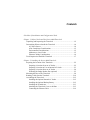
Contents
Checklist of Installation and Configuration Tasks
Chapter 1: Before You Install the Series 4000 Timeclock
Unpacking and Inspecting the Timeclock ..................................................1-2
Determining Where to Install the Timeclock .............................................1-4
AC Power Source .................................................................................1-4
ADA Compliance Considerations ........................................................1-5
Environmental Considerations .............................................................1-5
Adherence to Local Codes ...................................................................1-5
Ethernet Cabling Considerations .........................................................1-6
Tools Required to Install the Timeclock ....................................................1-7
Chapter 2: Installing the Series 4000 Timeclock
Preparing the Location of the Timeclock ...................................................2-2
Preparing a Location Over an AC Outlet .............................................2-2
Preparing a Location to Use an Internal AC Outlet .............................2-3
Preparing a Location Near an AC Outlet .............................................2-4
Widening the Badge Reader Slot (optional) ........................................2-5
Mounting the Base of the Timeclock .........................................................2-8
Running Cables Into the Timeclock .........................................................2-10
Assembling the Timeclock .......................................................................2-12
Installing the Optional Internal AC Outlet .........................................2-12
Installing the Optional Backup Battery ..............................................2-12
Installing the Transformer ..................................................................2-13
Attaching the Timeclock Cover to the Base ......................................2-15
Connecting the Ethernet Cable ..........................................................2-19
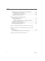
Contents
Supplying Power to the Timeclock and Verifying Operation .................. 2-21
Supplying Power to the Timeclock ................................................... 2-21
Verifying Operation of the Timeclock .............................................. 2-24
Closing and Locking the Timeclock ........................................................ 2-25
Chapter 3: Performing Local Configuration
Configuration Process Overview ............................................................... 3-2
Parts of the Timeclock ......................................................................... 3-2
Guidelines for Entering Information Using the Timeclock ................. 3-4
Completing Configuration Screens ............................................................ 3-5
Completing the Timeclock Configuration ................................................. 3-9
Other Series 4000 Documentation ........................................................... 3-10
Chapter 4: Troubleshooting Hardware and Operational Problems
Appendix A: Replacing a Series 400 Timeclock with a Series 4000
Timeclock
Read This First .......................................................................................... A-2
Disconnecting and Removing a Series 400 Timeclock ............................ A-3
Appendix B: Specifications and Optional Devices
vi
ADP, Inc.
Checklist of Installation and Configuration Tasks
_____
Unpack and inspect the Series 4000 badge timeclock. See page 1-2.
_____
Determine a suitable location for the Series 4000 timeclock. See page 1-4.
_____
Obtain communication settings to be used for the Series 4000 timeclock
from your network administrator. Settings include device ID, IP address, subnet
mask, and gateway.
_____
Plan access for Ethernet cable connections to and into the Series 4000
timeclock. See page 1-6.
_____
If necessary, widen the badge reader slot. See page 2-5.
_____
Prepare the location for the Series 4000 timeclock. See page 2-2.
_____
Mount the timeclock base. See page 2-8.
_____
Assemble the Series 4000 timeclock and connect all cables. See page 2-12.
_____
Remove the mylar strip from the lithium battery on the inside cover of the
timeclock. See page 2-21.
_____
Plug in the Series 4000 timeclock and verify that it is operating properly.
See page 2-21.
_____
Perform local configuration at the Series 4000 timeclock. See page 3-1.
_____
Add the Series 4000 timeclock as a device in your ADP system. For
guidance based on the host application you are using, see page 3-9.
_____
Test communication between the host application and the Series 4000
timeclock. For guidance based on the host application you are using, see
page 3-9.
_____
Perform remote configuration using installed ADP software. Includes
defining the badge timeclock’s features, functions and transactions. For
guidance based on the host application you are using, see page 3-9.
_____
Perform configuration at the ADP host application and download
information to the Series 4000 timeclock. For guidance based on the host
application you are using, see page 3-9.
Checklist of Installation and Configuration Tasks
viii
ADP, Inc.
Chapter 1
Before You Install the Series 4000 Timeclock
This chapter contains the following sections:
!
Unpacking and Inspecting the Timeclock
!
Determining Where to Install the Timeclock
!
Tools Required to Install the Timeclock
Chapter 1
Before You Install the Series 4000 Timeclock
Unpacking and Inspecting the Timeclock
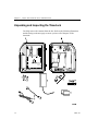
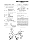
Carefully remove the contents from the box. Refer to the following illustration
and the listing on the next page to ensure you have all of the parts of the
timeclock.
1-2
ADP, Inc.
Unpacking and Inspecting the Timeclock
Number
Part
1
Cover assembly, including an integral bar code reader
2
Base of the timeclock and hinge
3
Power cord strain relief clip, with two screws and two nuts (packed
with other accessories in a plastic bag)
4
Security wrench, three pointed mounting screws, three anchors, and
two flat screws (not pointed)
5
Transformer
6
Plate and two nuts to convert square cable access opening in the
timeclock to a round opening (packed with other accessories in a
plastic bag)
7
Two power cords: 6 ft. (182.88 cm) to plug the timeclock into an
external AC outlet; 12 in. (30.48 cm) to plug in a timeclock mounted
over an AC outlet*
8
One supervisor badge, one maintenance badge (packed with other
accessories in a plastic bag)
* If you are located outside of the United States and Canada, your Series 4000 timeclock does not
include a power cord in the box. You must order an International Kit separately that contains the
appropriate power cord for use in your country.
A mounting template is also included to help you mark the position of the
timeclock.
Note
If you ordered either of the option kits (backup battery, internal AC outlet), they
are sent to you packaged separately in their own boxes, and with their own
installation instructions.
Series 4000 Badge Timeclock Installation Guide
1-3
Chapter 1
Before You Install the Series 4000 Timeclock
Determining Where to Install the Timeclock
Note
For instructions about how to replace an installed ADP Series 400 timeclock, see
Appendix A.
AC Power Source
The AC power source must be grounded 100 to 240 VAC, 50/60Hz input voltage.
The timeclock uses an integrated, autosensing, AC power transformer that
supports an IEC C-7 external power cord connection. This type of connection
allows the use of compatible international power cords.
Use one of the following methods to supply power to the Series 4000 timeclock.
The method you choose affects where and how you install the timeclock.
1-4
!
Mount over an AC outlet (recommended)—If you are mounting the
timeclock on drywall, this method secures the power connection inside the
timeclock. For instructions about determining the location of the AC outlet
and timeclock, see page 2-2.
!
Install an internal AC outlet—If you cannot mount the timeclock over an
AC outlet (for example, if you are mounting the timeclock on masonry), use
the internal AC outlet option (purchased separately from ADP). This method
secures the power connection inside the timeclock. For instructions about
preparing the location of the timeclock, see page 2-3.
!
Mount near an AC outlet—If you cannot mount the timeclock over an outlet
or use the internal AC outlet option, mount the timeclock near an AC outlet.
This method does not protect against the power cord from being deliberately
or inadvertently unplugged from the outlet. You must plug the timeclock
directly into the AC outlet; do not plug the timeclock into an extension cord
or power strip. For detailed instructions, see page 2-4.
ADP, Inc.
Determining Where to Install the Timeclock
ADA Compliance Considerations
Consider the following for compliance with the Americans with Disabilities Act
(ADA). These are the regulations in effect at the time this documentation was
written; if you are in doubt about the regulations, ADP recommends that you
check the current ADA requirements.
!
Plan the installation so that when you mount the timeclock, the top two
mounting screws are no higher than 54 and 3/8 inches (138.09 cm) above the
floor. This ensures that no part of the timeclock that personnel will physically
use (badge reader, keypad) will be higher than the limit set by ADA.
!
Devices mounted on a wall must not protrude more than 4 inches (10 cm)
from the wall. You must mount the timeclock directly to the wall.
Environmental Considerations
Consider the following when deciding where to install the Series 4000 timeclock:
!
The timeclock is designed for mounting on walls in typical office and indoor
manufacturing environments. Recommended wall surfaces are drywall
(sheetrock) and wood.
!
The timeclock can withstand the following temperature and humidity ranges:
!
–
Temperature ranges
Operating: 0 to 40 degrees Celsius (32 to 104 degrees Fahrenheit)
Storage: -20 to +70 degrees Celsius (4 to 158 degrees Fahrenheit)
–
Humidity range (operating and storage): 10% to 95% non-condensing
Install the timeclock in an area where the timeclock screen is not exposed to
direct sunlight or other high-intensity lighting that could make the screen
difficult to read.
Adherence to Local Codes
Installation of the Series 4000 timeclock, including all electrical wiring, must
comply with all applicable national, federal, state, and local codes and standards.
Series 4000 Badge Timeclock Installation Guide
1-5
Chapter 1
Before You Install the Series 4000 Timeclock
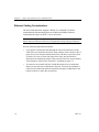
Ethernet Cabling Considerations
The Series 4000 timeclock supports 10BASE-T or 100BASE-T Ethernet
communication and autosensing between 10Mbit and 100Mbit. Ethernet
communication requires an RJ-45, 8-wire connection.
Note
Ensure that your Ethernet cable meets all applicable wiring code specifications.
Note the following important information:
!
If you plan to run Ethernet cable through the wall to the timeclock, run the
cable before you install the timeclock. Ensure that the cable exits the wall at a
point where it can enter the installed timeclock, and that you provide at least
20 inches (50.8 cm) of slack from the point of entry into the timeclock.
Instructions for marking the point of entry into the timeclock are presented in
“Preparing the Location of the Timeclock,” beginning on page 2-2.
!
1-6
To connect to an external wall jack, install the timeclock in a location that
allows an easy and secure connection to the jack. You must run an Ethernet
cable from its connection inside the timeclock, through a conduit hole in the
bottom of the base, and to the external jack.
ADP, Inc.
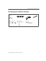
Tools Required to Install the Timeclock
Tools Required to Install the Timeclock
Tape
measure
Level
Electric drill
Phillips screwdriver
Security wrench
(ships with timeclock)
Keyhole saw
Series 4000 Badge Timeclock Installation Guide
Utility knife
1-7
Chapter 1
1-8
Before You Install the Series 4000 Timeclock
ADP, Inc.
Chapter 2
Installing the Series 4000 Timeclock
This chapter contains the following sections:
!
Preparing the Location of the Timeclock
!
Mounting the Base of the Timeclock
!
Assembling the Timeclock
!
Supplying Power to the Timeclock and Verifying Operation
Chapter 2
Installing the Series 4000 Timeclock
Preparing the Location of the Timeclock
This section explains how to mark and prepare the timeclock location, depending
on how you plan to supply AC power to the timeclock.
Preparing a Location Over an AC Outlet
This is the recommended method of mounting the timeclock.
Caution
You must have a licensed electrician install the AC outlet before you install the
Series 4000 timeclock.
The AC line that supplies power to the timeclock must be equipped with an
appropriate disconnect device (proper fuse or circuit breaker). Do not connect the
Series 4000 timeclock’s power line to circuits being used for electrical devices
that draw large amounts of power, such as air conditioning units, electrical
motors, and compressors. Also avoid running communications cable near devices
that interfere with data transmission.
Attention
Vous devez faire appel à un électricien agréé pour installer la prise c.a. avant
d’installer le terminal Series 4000.
La source utilisée pour alimenter le terminal doit être munie d’un dispositif de
disjonction adéquat (fusible ou disjoncteur de circuit). Ne branchez pas le
terminal Series 4000 sur les mêmes circuits que ceux qui alimentent des appareils
électriques qui consomment beaucoup de courant, comme les climatiseurs, les
moteurs et les compresseurs. En outre, assurez-vous que le cable de
communication ne passe pas près d’appareils électriques qui pourraient causer des
interférences et nuire à la transmission des données (par exemple, les gros
moteurs, les ballasts et les transformateurs).
2-2
ADP, Inc.
Preparing the Location of the Timeclock
1. Tape the mounting template at the desired height and location for the
timeclock. The top two mounting screws must be no higher than 54 and 3/8
inches (138.09 cm) above the floor, for ADA compliance.
2. Mark the location for the AC outlet and the mounting screw holes.
3. If you plan to run Ethernet cable through the wall to enter the timeclock from
the back, use the template to mark the point of entry.
4. Have a licensed electrician install the AC outlet.
5. If necessary, run the Ethernet cable through the wall and out the point of entry
into the timeclock. Provide 20 inches (50.8 cm) of slack.
Go to “Widening the Badge Reader Slot (optional)” on page 2-5 and then to
“Mounting the Base of the Timeclock” on page 2-8.
Preparing a Location to Use an Internal AC Outlet
1. Tape the mounting template at the desired height and location for the
timeclock. The top two mounting screws must be no higher than 54 and 3/8
inches (138.09 cm) above the floor.
2. Mark the location of the mounting screw holes.
3. If you will run an AC power line through the wall and into the timeclock,
mark the cable’s point of entry into the timeclock, as indicated on the
template.
You can also choose to run the AC power line externally, through conduit, and
in through the bottom of the timeclock. To do this, the AC power line must be
CL-2 or higher.
4. If you plan to run the Ethernet cable to enter the timeclock from the back, use
the template to mark the point of entry.
5. Run the AC power line and Ethernet cable to the timeclock location. For the
Ethernet cable, allow 20 inches (50.8 cm) of slack.
Go to “Widening the Badge Reader Slot (optional)” on page 2-5 and then to
“Mounting the Base of the Timeclock” on page 2-8. You will assemble and
connect the internal AC outlet after you install the base.
Series 4000 Badge Timeclock Installation Guide
2-3
Chapter 2
Installing the Series 4000 Timeclock
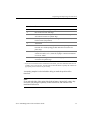
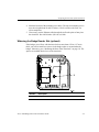
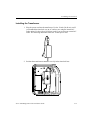
Preparing a Location Near an AC Outlet
Note
Use this method only if you cannot mount the timeclock over an AC outlet or use
the internal AC outlet option. This method does not protect against the AC power
cord from being deliberately or inadvertently unplugged from the outlet.
1. Select a location where the distance from the knockout for the power cable at
the bottom of the timeclock to the AC outlet is not more than 5 feet (152.40
cm). Also, the top two mounting screws must be no higher than 54 and 3/8
inches (138.09 cm) above the floor.
Maximum of
54 inches
(138.09 cm.)
from floor to
top mounting
screws
2. Tape the mounting template at the desired height and location.
3. If you plan to run the Ethernet cable through the wall to enter the timeclock
from the back, mark the point of entry as indicated on the template.
2-4
ADP, Inc.
Preparing the Location of the Timeclock
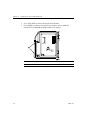
4. Mark the location of the mounting screw holes. The top two mounting screws
must be no higher than 54 and 3/8 inches (138.09 cm) above the floor, for
ADA compliance.
5. If necessary, run the Ethernet cable through the wall at the point of entry into
the timeclock. Provide 20 inches (50.8 cm) of slack.
Widening the Badge Reader Slot (optional)
If the badges you will use with the timeclock are more than .050 in (1.27 mm)
thick, you need to install two spacers in the badge reader to accommodate the
badges. Otherwise, go to “Mounting the Base of the Timeclock” on page 2-8. The
spacers are molded into the base of the timeclock.
Number
Description
1
Badge reader spacers molded into the base.
Series 4000 Badge Timeclock Installation Guide
2-5
Chapter 2
Installing the Series 4000 Timeclock
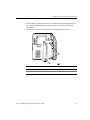
1. Use a utility knife to remove the spacers from the base.
2. Use a Phillips screwdriver to loosen the two captive screws inside the
timeclock cover that hold the badge reader cover in place.
2-6
Number
Description
1
Screws that hold the badge reader cover in place
ADP, Inc.
Preparing the Location of the Timeclock
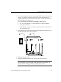
3. On the outside of the timeclock cover, press the two spacers onto the tops of
the channels that hold the screws for the reader cover. (See the following
illustration.)
4. Position the reader cover back into place and tighten the two screws.
Number Description
1
Badge reader spacers
2
Reader cover
Series 4000 Badge Timeclock Installation Guide
2-7
Chapter 2
Installing the Series 4000 Timeclock
Mounting the Base of the Timeclock
After you have properly prepared the location for the timeclock, use the following
procedure to mount the base of the timeclock to the wall:
1. If you are installing the timeclock over an AC outlet, remove the knockout in
the base of the timeclock. Do this by cutting the plastic tabs with a keyhole
saw. Refer to the following illustration for the location of the knockout.
2-8
Number
Description
1
Knockout for AC outlet (plastic tabs indicated by “X”)
ADP, Inc.
Mounting the Base of the Timeclock
2. If you are mounting the timeclock on wood, drill pilot holes for the mounting
screws. Use a drill or screwdriver to drive the top two mounting screws
(supplied with the timeclock) into the wall, leaving 1/4 inch (6 mm) between
the head of the screw and the wall.
If you are mounting the timeclock on drywall, do the following:
a. Use a 9/32 inch drill bit (7.1 mm) to drill holes for the wall anchors.
b. Install the wall anchors.
c. Install the top two screws, leaving 1/4 inch (6 mm) between the head of
the screw and the wall.
3. Align the top two screw holes in the base of the timeclock with the screws in
the wall, and gently set the base in position.
4. Tighten the top two screws.
5. Install and tighten the bottom screw to secure the base to the wall.
Note
Do not install the screws too tightly. If the wall surface is not smooth, you
could crack the housing by excessive tightening of the screws.
Series 4000 Badge Timeclock Installation Guide
2-9
Chapter 2
Installing the Series 4000 Timeclock
Running Cables Into the Timeclock
The base of the timeclock has cable access holes in the top right portion of the
base and in the metal plate at the bottom of the base. See the following illustration.
2-10
Number
Description
1
Access holes for running cables into the back of the timeclock
2
Access holes for running cables into and out of the timeclock
ADP, Inc.
Running Cables Into the Timeclock
Use the following guidelines and procedures when routing cables in and out of the
timeclock:
Routing cables through
the wall and into the
timeclock
For the Ethernet cable, ensure that there is at least 20 inches
(50.8 cm) of slack after the point of entry into the timeclock.
Routing an external
Use the round access holes in the metal plate at the bottom of
cable up through the
the timeclock as follows:
bottom of the timeclock 1. Remove a round knockout for conduit by pressing on it
firmly and carefully.
2. Install a cable clamp in the conduit opening.
3. Run the cable through the clamp, providing the following
slack:
! AC power line: 12 inches (30.48)
! Ethernet cable: 11 inches (27.94 cm)
4. Tighten the screws on the clamp to secure the cable.
The following illustration shows how your cable routing
should look. Callout 1 indicates the location of the cable clamp
assembly.
Routing the AC power
cord from inside the
timeclock to an external
AC outlet
Later in the installation procedure, you will use the rectangular
access hole in the metal plate at the bottom of the timeclock,
securing the cable with the strain relief assembly.
Note
If you want to run an AC power line through conduit, the line
must be CL-2 or higher.
Series 4000 Badge Timeclock Installation Guide
2-11
Chapter 2
Installing the Series 4000 Timeclock
Assembling the Timeclock
After you have mounted the base of the timeclock to the wall (see “Mounting the
Base of the Timeclock” beginning on page 2-8), you are ready to assemble and
connect the parts of the timeclock.
Note
The illustrations in these procedure show a timeclock installed directly over an
AC outlet. However, the procedure notes alternative steps if you are using the
internal AC outlet option or mounting the timeclock near a wall outlet.
Installing the Optional Internal AC Outlet
If this timeclock will use an internal AC outlet, refer now to the instructions in the
Internal AC Outlet Option Kit Installation Guide that you received with the option
kit. Before you begin the internal AC outlet installation, ensure that power to the
AC line is shut off.
When you finish installing the internal AC outlet, follow the instructions under
“What To Do Next” in that guide.
Installing the Optional Backup Battery
To install the backup battery, refer now to the instructions in the Backup Battery
Option Kit Installation Guide that you received with the option kit. When you
finish installing the backup battery, return to this guide to complete the installation
of the timeclock.
2-12
ADP, Inc.
Assembling the Timeclock
Installing the Transformer
1. Plug the power cord into the transformer. Use the 12-inch (30.48 cm) cord if
you mounted the timeclock over an AC outlet or are using the internal AC
outlet option. Use the 6-foot (182.88 cm) cord if you are using an external AC
outlet. The following illustration shows the 12-inch power cord.
2. Position the transformer behind the wire clip in the timeclock base.
Series 4000 Badge Timeclock Installation Guide
2-13
Chapter 2
Installing the Series 4000 Timeclock
Warning
Do not plug the power cord into the AC power source yet.
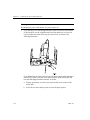
3. If you ran the power cord through the square cable access hole in the bottom
of the timeclock, use the supplied strain relief clip and screws to secure the
cord. Assemble the strain relief clip, nuts, and screws, as shown in the
following illustration.
If you did not use the square cable access hole in the bottom of the terminal to
run the power cable, cover the access hole using the square black plate and
two nuts that shipped with the terminal. To do this:
a. Slip the square plate over the screw posts located at two corners of the
access hole.
b. Screw the two nuts onto the posts to secure the plate in place.
2-14
ADP, Inc.
Assembling the Timeclock
Attaching the Timeclock Cover to the Base
1. Release the plastic hinge clip by squeezing the retainers at each hinge
position. Squeeze each retainer one at a time until you feel the clip release.
2. Rotate the hinge clip to the left.
Series 4000 Badge Timeclock Installation Guide
2-15
Chapter 2
Installing the Series 4000 Timeclock
3. Fit the two hinges on the cover into the corresponding areas molded in the
base.
2-16
Number
Description
1
Recessed areas in the timeclock base for seating the hinges
ADP, Inc.
Assembling the Timeclock
4. Carefully close the cover of the timeclock, making sure that the two hinges
remain properly seated in place.
Caution
After the cover is closed, continue to hold it securely in place as you perform
the next step.
Series 4000 Badge Timeclock Installation Guide
2-17
Chapter 2
Installing the Series 4000 Timeclock
5. Rotate the hinge clip forward until it snaps into place.
6. Open the cover and install the two small, flat (not pointed) screws to secure
the hinge clip, as shown in the following illustration.
2-18
ADP, Inc.
Assembling the Timeclock
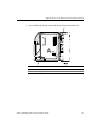
Connecting the Ethernet Cable
The following illustration shows how to connect the Ethernet cable if you ran the
cable through the wall and into the back of the timeclock. Use the hooks molded
into the base of the timeclock to secure the cable along its route. Also, avoid
excessive bending or crimping of the cable.
Number
Description
1
Ethernet cable (through the wall and into the back of the timeclock)
2
Ethernet connection to the timeclock’s main board
Series 4000 Badge Timeclock Installation Guide
2-19
Chapter 2
Installing the Series 4000 Timeclock
The following illustration shows how to connect the Ethernet cable if you ran the
cable through the bottom of the timeclock:
2-20
Number
Description
1
Ethernet cable
2
Ethernet connection to the timeclock’s main board
ADP, Inc.
Supplying Power to the Timeclock and Verifying Operation
Supplying Power to the Timeclock and Verifying
Operation
The illustrations in this section assume that you have installed the backup battery,
and that you ran the Ethernet cable through the wall and into the back of the
timeclock. However, the procedure in this section applies to all installation
scenarios.
Supplying Power to the Timeclock
1. Remove the mylar strip from the lithium battery located on the main board in
the cover of the timeclock.
Series 4000 Badge Timeclock Installation Guide
2-21
Chapter 2
Installing the Series 4000 Timeclock
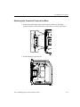
2. Connect the transformer cable to the timeclock’s main board. To do this, run
the cable up the left side of the transformer as shown in the following
illustration. Use the hooks molded into the base of the timeclock and the
channel along the top of the cover to secure the cable along its route.
2-22
Number
Description
1
Transformer cable
2
Hooks for routing the cable
3
Transformer connection to the main board (DC power)
ADP, Inc.
Supplying Power to the Timeclock and Verifying Operation
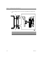
3. If you installed the battery, connect the charger board to the main board.
Number
Description
1
Battery charger board cable that connects to the main board
2
Charger board connection to the main board
Series 4000 Badge Timeclock Installation Guide
2-23
Chapter 2
Installing the Series 4000 Timeclock
4. Plug the transformer into the AC power source as shown. If you ran the power
line to an external AC outlet, plug the cord in now.
Over an AC outlet (top receptacle)
Using an internal AC outlet
Note
When the Series 4000 timeclock is first powered and running, the optional
backup battery is not yet charged. It takes approximately 24 hours for the
battery to fully charge itself.
5. Close the cover of the timeclock enough so that you can view the display
screen as the timeclock initializes itself.
2-24
ADP, Inc.
Supplying Power to the Timeclock and Verifying Operation
Verifying Operation of the Timeclock
When you supply power to the timeclock, it initializes itself, performs internal
diagnostics, and starts the operating system and timeclock application. This
process takes approximately one minute.
If the initialization completes successfully, the Communications Setting screen
appears. Go to page 2-26, then to Chapter 3, “Performing Local Configuration.”
Changing comm settings causes a reboot!
Device ID
IP Address
Gateway
Subnet Mask
If the Communication Setting screen does not appear, the timeclock did not
initialize successfully. Contact your TLM Representative.
Series 4000 Badge Timeclock Installation Guide
2-25
Chapter 2
Installing the Series 4000 Timeclock
Closing and Locking the Timeclock
When the timeclock is operating properly, close the timeclock cover and lock it
using the security wrench to tighten the security screw on the cover.
Caution
When you close the cover, ensure that you are not closing it on any of the cables
inside the timeclock. Do not force the cover when closing it.
Number
Description
1
Security screw
2
Security wrench
You are now ready to configure the timeclock. Go to Chapter 3, “Performing
Local Configuration.”
2-26
ADP, Inc.
Chapter 3
Performing Local Configuration
This chapter contains the following sections:
!
Configuration Process Overview
!
Completing Configuration Screens
!
Completing the Timeclock Configuration
Chapter 3
Performing Local Configuration
Configuration Process Overview
There are two basic tasks involved in configuring the Series 4000 timeclock:
!
Local configuration—Includes settings to establish communication with the
host application, Ethernet communication characteristics, time and date, and
the appearance of the display. You must perform local configuration first.
!
Remote configuration—Includes defining which functions and transactions
users can perform at the timeclocks. You use the host application to configure
the timeclock.
Note
This chapter explains how to perform local configuration only.
Parts of the Timeclock
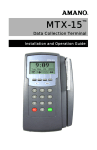
The following illustration shows the parts of the Series 4000 timeclock. Refer to
the table on the next page for descriptions of each part indicated.
3-2
ADP, Inc.
Configuration Process Overview
Number
Part
1
Numeric keypad for data entry—Use to enter information when
performing transactions and functions at the timeclock.
2
Navigational keys—Use to move within fields and scroll through lists.
3
Soft keys—Use to initiate transactions and functions at the timeclock.
You program each soft key using the Data Collection Manager (DCM)
if your host application is Enterprise eTIME, or Configuration Manager
if your host application is eTIME.
4
Display—1/4 VGA screen that displays soft key labels, possible
functions, transaction steps, and transaction output.
5
LEDs—Visual indicators:
The top LED is green and flashes when the timeclock successfully reads
a badge that is swiped by a user.
The middle LED is amber and flashes when the timeclock does not
successfully read a badge that is swiped by a user.
The bottom LED is amber and indicates whether the timeclock is
receiving power.
6
Badge reader (barcode)—Use to read employee, supervisor, and
maintenance badges when swiping in and out and performing
transactions and functions.
7
Security screw—Use to secure the timeclock’s cover. Use the supplied
security screw wrench to lock and unlock the cover.
8
Additional keys—ESC, Help, backspace and delete, CLEAR, and
ENTER.
Series 4000 Badge Timeclock Installation Guide
3-3
Chapter 3
Performing Local Configuration
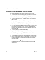
Guidelines for Entering Information Using the Timeclock
Use the following guidelines when entering information using the keypad:
!
To display settings for a menu item, press the soft key next to the menu item.
!
To save settings on a screen, press ENTER at the last prompt.
To cancel the transaction you are performing, press ESC at any time.
!
To move the cursor in a text field, use the left and right arrow keys directly
under the display.
!
To move the cursor to different text fields, use the up and down arrow keys
directly under the display.
!
The active text field (field in which the cursor is currently located) is
indicated by an outline of the text box and a flashing cursor.
!
If you enter characters in a field that already contains data, the existing data is
not overwritten; it is pushed to the right. To remove individual characters,
position the cursor immediately to the right of the characters, and press the
Backspace key (").
!
To clear all characters in a field, press the CLR key.
!
If you complete a field incorrectly and move to the next field, an error
message appears at the top of the display.
!
To save data that you entered, press the ENTER key at the last field on the
screen.
!
To restore the previous settings on a configuration screen, press the ESC key.
!
Black up and down arrows appear at the bottom middle of the screen if there
is additional information to display before or after the current screen. The
arrows look like this:
Use the up and down arrow keys directly under the screen to move to the
various screens.
3-4
ADP, Inc.
Completing Configuration Screens
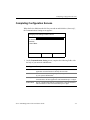
Completing Configuration Screens
When the Series 4000 timeclock is first powered on and initializes (“boots up”),
the Communications Setting screen appears:
Changing comm settings causes a reboot!
Device ID
IP Address
Gateway
Subnet Mask
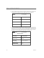
1. On the Communication Setting screen, complete the following fields, with
the help of your network administrator:
Settings
Description
Device ID
Enter an ID number (at least six digits) for the timeclock. The host
application uses this number to identify the timeclock.
IP Address
Enter the IP address, including the periods, assigned to the timeclock
by your system administrator.
Gateway
Enter the IP address, including the periods, of the default device that
forwards data to the host application. This field holds up to 15 digits.
Subnet Mask
Specify a number that identifies a subnetwork so that an IP address
can be found on a LAN. This field holds up to 15 digits.
Series 4000 Badge Timeclock Installation Guide
3-5
Chapter 3
Performing Local Configuration
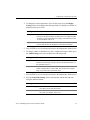
2. Press ENTER at the last prompt. The timeclock reboots itself so that the new
communications settings take effect, and then the idle screen appears:
2:03
PM
Fri 17–Aug–2001
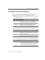
3. Swipe the Maintenance badge that came with the Series 4000 timeclock (the
badge has an “M” on the front). To do this, hold the badge so that the bar code
is positioned on the back left edge and swipe the badge up or down through
the reader’s slot. The Maintenance Mode menu screen appears:
2:03
PM
Fri 17–Aug–2001
Maintenance Mode
3-6
Comm Setting
Symbology Setting
Display Setting
Restart
Audio Setting
FACTORY DEFAULT
Date/Time Setting
More...
ADP, Inc.
Completing Configuration Screens
4. To change the current appearance of text on the screen, press the Display
Setting soft key and complete the following fields. To quickly set a field to its
minimum value, press CLR.
Settings
Description
Contrast
Use the + and - keys indicated at the bottom of the screen to
increase or decrease the degree of difference between light and dark
extremes of color on the timeclock’s display. The minimum value is
16; the maximum value is 22.
Brightness
Use the + and - keys indicated at the bottom of the screen to
increase and decrease the brightness of the timeclock display.
5. Press ENTER to save the settings and return to the Maintenance Mode screen.
6. To change, enable, or disable the key click, or adjust the beeper volume, press
the Audio Setting soft key and complete the following fields:
Settings
Description
Beeper volume Use the + and - keys indicated at the bottom of the screen to increase
and decrease the degree of beeper volume. The minimum value is 1;
the maximum value is 7.
Key click
Use the Off and On keys indicated at the bottom of the screen to
enable or disable the key click sound. The Off/On choices appear
when you position the cursor in this field.
7. Press ENTER to save the settings and return to the Maintenance Mode screen.
8. Press the Date/Time Setting soft key and enter the current date and time
using the indicated format.
Settings
Description
Date (mm/dd/yyyy) Enter the current month, day, and year. For the year, enter all
four digits. Do not enter the slashes.
Time (24 hour)
Enter the current time of day in 24-hour format. Do not enter
the colon. For example, enter 1730.
Series 4000 Badge Timeclock Installation Guide
3-7
Chapter 3
Performing Local Configuration
9. Press ENTER to save the settings and return to the Maintenance Mode screen.
10. Press the Symbology Setting soft key and use the On and Off soft keys to
indicate the type of bar codes used on your employees’ badges. This allows
the timeclock to read the badges properly.
Symbology Setting
Code 3-of-9:
12-of-5:
UPC-A:
UPC-E:
Code 128:
EAN-8:
EAN-13:
Codabar:
Off
On
Off
Off
Off
Off
Off
Off
On
Off
11. Press ENTER to save the settings and return to the Maintenance Mode screen.
12. To create a password that allows access to the Maintenance Mode screen in
the future, press the More soft key and then the Change Password soft key.
Complete the following fields:
Settings
Description
Old Password
Enter the old password, if there was one.
New Password
Enter the new password.
Verify Password
Enter the new password again to verify that you entered it
correctly.
13. Press ENTER to save the password and return to the Maintenance Mode
screen.
14. Press ESC to exit Maintenance Mode and return to the idle screen.
3-8
ADP, Inc.
Completing the Timeclock Configuration
Completing the Timeclock Configuration
This section lists the tasks necessary to finish configuring the timeclock, where in
the host software to perform each task, and documentation to reference.
!
!
Add the timeclock to your system configuration, and assign it to a domain and
a communication channel.
Host application
What to do
eTIME
Use Configuration Manager to add data collection timeclocks
(Timeclocks > Timeclocks > New). See the eTIME
Configuration Manager Reference and the online Help.
Enterprise eTIME
In DCM, use the Device Wizard or Advanced Device
Manager. See the Data Collection Manager System
Administrator’s Guide and the online Help.
Test communication between the host application and the timeclock.
Host application What to do
!
eTIME
Use Configuration Manager to test communication as part of
adding a timeclock. See the eTIME Configuration Manager
Reference and the online Help.
Enterprise eTIME
In DCM, use the Device Manager. See the Data Collection
Manager System Administrator’s Guide and the online Help.
Define the transactions you want users to be able to perform at the timeclock.
Host application
What to do
eTIME
Use Configuration Manager to define transactions that can
be performed at the timeclock (Timeclocks > Timeclocks,
select a timeclock, click the arrow next to the Open button,
and select Basic Configuration). See the eTIME
Configuration Manager Reference and the online Help.
Series 4000 Badge Timeclock Installation Guide
3-9
Chapter 3
Performing Local Configuration
Enterprise eTIME,
Workforce Smart
Scheduler
!
In DCM, use Device Manager. See the Data Collection
Manager System Administrator’s Guide and the online
Help.
Define what type of data to download from the host application to the
timeclock (for example, activity codes, pay codes, labor level entries).
Host application
What to do
eTIME
Use the Configuration Manager to download the necessary
data to the timeclock, based on the transactions you set up
(Timeclocks > Timeclocks, select a terminal, click the
arrow next to the Open button, and select Download
Options). See the eTIME Configuration Manager
Reference and the online Help.
Enterprise eTIME,
Workforce Smart
Scheduler
Use the Setup application to configure the features you
want to use. Refer to the online Help.
In DCM, use Device Manager to download the necessary
data to the timeclock, based on the transactions you set up
for the timeclock. See the Data Collection Manager System
Administrator’s Guide and the online Help.
Other Series 4000 Documentation
When you are ready to use the Series 4000 timeclock, refer to the Series 4000
Badge Timeclock User’s Guide. This document is not shipped with the timeclock;
you must order it separately.
3-10
ADP, Inc.
Chapter 4
Troubleshooting Hardware and Operational
Problems
This chapter presents instructions for troubleshooting and resolving problems
related to physically installing the timeclock and ensuring that it is operating
correctly.
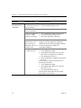
Symptom
Probable Causes
Corrective Action
The Series 4000
timeclock does not
power up, and the
power LED is not
turned on.
The transformer is not
plugged in properly to the
timeclock’s main board,
the AC outlet, or both.
Check the connections to the main board and the
AC outlet.
Important: If the power cord is not plugged into
the AC outlet, do not plug it in until you ensure that
the transformer is properly connected to the main
board.
For instructions, see “Supplying Power to the
Timeclock,” beginning on page 2-21.
The power LED is
turned on, but
nothing appears on
the screen.
The AC line is not live or Measure voltage at AC outlet and, if necessary,
is supplying improper
locate another power source.
voltage.
The display’s cable is not
connected to the main
board.
Contact your TLM Representative.
Chapter 4
Troubleshooting Hardware and Operational Problems
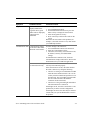
Symptom
Probable Causes
Corrective Action
Series 4000
timeclock fails to
read badges.
The badge is unreadable or 1. Inspect the badge for cleanliness.
does not meet the required 2. Clean the badge and badge reader.
badge specification.
The bar code on the badge Replace the badge.
is worn or scraped off.
You did not configure the 1. Access Maintenance Mode at the timeclock.
2. Press the Symbology Setting soft key.
timeclock to read the
3. Turn on the appropriate symbology.
symbology your badges
use.
The timeclock is not
enabled for the correct
badge reader type or
company ID code (if you
are using a code).
Correct the badge reader and company ID code
settings. If your host application is Enterprise
eTIME, use the Data Collection Manager (DCM);
if your host application is eTIME, use
Configuration Manager
The badge reader may not Run the Badge Test test at the timeclock:
be working correctly.
1. Access Maintenance Mode.
2. On the Maintenance Mode screen, press the
More soft key to display the test functions.
3. Press the Badge Test soft key.
4. Follow the prompts to conduct the test and note
the result.
If the test does not indicate the problem, run a
Reader Report as follows:
1. Access Maintenance Mode.
2. On the Maintenance Mode screen, press the
More soft key twice.
3. Press the Reader Report soft key.
Note the report results and contact your TLM
Representative for assistance.
4-2
ADP, Inc.
Symptom
Probable Causes
Corrective Action
Keypad fails to work. The timeclock did not
properly initialize the
keypad or the keypad’s
ribbon cable is improperly
connected to the
mainboard.
Run the Keypad Test test at the timeclock:
Communication fails. Communication settings
are incorrect either at the
timeclock or the host PC.
To check settings at the timeclock:
Communications cabling
is connected incorrectly.
1. Access Maintenance Mode.
2. On the Maintenance Mode screen, press the
More soft key to display the test functions.
3. Press the Keypad Test soft key.
4. Press various keys and note the results on the
screen.
Determine the exact nature of the problem (for
example, is the cable twisted or cut?), then contact
your TLM Representative.
1. Access Maintenance Mode at the timeclock.
2. Press the Comm Setting soft key.
3. Check and, if necessary, correct the Device ID,
IP Address, Gateway, and Subnet Mask
settings.
If communication continues to fail, check the
communication settings at the host PC. Refer to the
documentation for your ADP host application.
Ensure that all communications cables are routed
correctly and connected properly.
If the connections are secure, determine whether
the cable is defective by doing the following:
!
Check to see if the green communications LED
inside the Series 4000 timeclock is lit. Use the
security wrench to unlock and open the cover of
the timeclock. The green LED is located inside
the cover and to the left of the Ethernet
connection on the main board.
! Check to see if the green link light on the hub to
which the timeclock is connected.
If both lights are lit, the cable is not defective. The
problem may lie in the network configuration.
If both lights are not lit, the cable may be defective.
Consult with your system administrator to resolve
the problem.
Series 4000 Badge Timeclock Installation Guide
4-3
Chapter 4
4-4
Troubleshooting Hardware and Operational Problems
ADP, Inc.
Appendix A
Replacing a Series 400 Timeclock with a Series 4000
Timeclock
This appendix contains the following sections:
!
Read This First
!
Disconnecting and Removing a Series 400 Timeclock
Appendix A
Replacing a Series 400 Timeclock with a Series 4000 Timeclock
Read This First
Before you replace an installed Series 400 timeclock with a Series 4000 timeclock
at your site, note the following information:
!
Remember to collect data from the Series 400 timeclock using your host
application before you disconnect the timeclock.
!
The Series 4000 timeclock supports Ethernet communication only; it does not
support modem, token ring, twin axial, RS-485, or RS-232 communications.
Therefore, do not replace a Series 400 timeclock if it does not use Ethernet
communication and you want the timeclock at that location to continue using
one of the other methods.
!
The location of the mounting screw holes for both the Series 400 timeclock
and the Series 4000 timeclock are identical. You can install the Series 4000
timeclock in exactly the same location as the timeclock you are replacing.
However, ensure that the location satisfies the following requirements:
–
To comply with the Americans with Disabilities Act (ADA), the top of the
timeclock cannot be greater than 54 and 3/8 inches (138.09 cm) above the
floor.
–
If the Series 4000 timeclock will be plugged into a wall outlet away from
the timeclock (the timeclock is not mounted to cover an AC outlet), the
timeclock cannot be more than 5 feet (152.40 cm) away from the outlet.
Caution
If the Series 400 timeclock you are replacing uses an internal AC outlet, you must
have a licensed electrician disconnect the power line from the outlet.
Attention
Si le terminal de la série 4000 que vous remplacez est relié par une prise c.a.
interne, vous devez faire appel à un électricien agréé pour débrancher la prise de
la source d'alimentation.
A-2
ADP, Inc.
Disconnecting and Removing a Series 400 Timeclock
Disconnecting and Removing a Series 400 Timeclock
Caution
Before you begin, collect data from the Series 400 timeclock using your host
application. If you do not do this now, the data will be lost.
To disconnect and remove a Series 400 timeclock from the wall:
1. Collect data from the timeclock, using your host application. If you do not do
this now, the data will be lost.
2. Unlock the cover of the timeclock using the hex wrench that came with the
Series 400 timeclock to loosen the security screw on the left side of the cover.
3. Carefully open the cover of the timeclock.
4. Disconnect the timeclock from its AC power source. Depending on how the
timeclock was installed, do one of the following:
!
Unplug the power cord from an AC outlet external to the timeclock.
!
If the timeclock was mounted to cover an AC outlet, unplug the power
cord from that outlet.
!
If you used the internal AC outlet option, unplug the power cord from the
internal outlet.
5. If power was supplied to the timeclock using an internal AC outlet, have a
licensed electrician disconnect the power line from the outlet now.
Series 4000 Badge Timeclock Installation Guide
A-3
Appendix A
Replacing a Series 400 Timeclock with a Series 4000 Timeclock
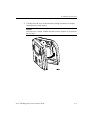
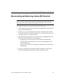
6. Disconnect the cable from the Ethernet board inside the cover of the
timeclock. See the following illustration.
Number
Description
1
Ethernet board
2
Main board
3
Ethernet connection
7. If the Ethernet cable was routed through the bottom of the timeclock, remove
the cable from inside the timeclock.
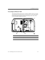
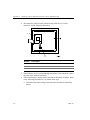
8. If the timeclock has a backup battery, disconnect the battery as follows. Refer
to the following illustration as you perform these steps.
a. Disconnect the battery charger board from the terminals on the backup
battery.
A-4
ADP, Inc.
Disconnecting and Removing a Series 400 Timeclock
b. Disconnect the battery charger board from the timeclock’s main board
(inside the cover).
2
1
3
Number
Description
1
Battery
2
Battery charger board connections to the backup battery
3
Battery charger board connection to the main board
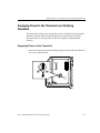
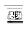
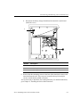
9. Remove the three mounting screws in the base of the timeclock to remove the
timeclock from the wall. The screws are located in the top left and right
corners, and the bottom middle of the base.
You are now ready to install the Series 4000 timeclock. For detailed instructions,
go to Chapter 2, “Installing the Series 4000 Timeclock.”
Series 4000 Badge Timeclock Installation Guide
A-5
Appendix A
A-6
Replacing a Series 400 Timeclock with a Series 4000 Timeclock
ADP, Inc.
Appendix B
Specifications and Optional Devices
Case:
Black, advanced polycarbonate/ABS resin, dust and moistureresistant
Dimensions:
Width: 10.75 inches (27.30 cm)
Height: 11.75 inches (29.85 cm)
Depth: 4 inches (10.16 cm)
Shipping weight:
5 lbs. (2.25 kg)
Keypad:
Silicon Elastomer numeric keypad and 8 programmable soft
keys
Power supply:
50/60 Hz 110/220 V transformer
Power requirements: 100 to 240V, 1.5A maximum
Display:
4 x 40 FSTN LCD
Host communicatons: 10/100 Mbit auto-sensing Ethernet
CPU:
Motorola MPC 860DT
Memory:
16 MB RAM, upgradable to 64 MB
8 MB Flash, ability to upgrade to 100 MB
Badge reader:
Integrated bar code badge reader
Battery backup:
Optional, 12 VDC lead acid battery to provide the timeclock up
to two hours of full functioning operation
Operating
environment:
Temperature: 0 to 40 degrees Celsius, 32 to 104 degrees
Fahrenheit
Humidity: 10% to 95% non-condensing
Shock resistance:
Withstands 40 G’s of force when packed in original shipping
carton
ESD protection:
Withstands 20 kV electrostatic discharge without failures
Appendix B
Specifications and Optional Devices
AC surge protection: Timeclock withstands AC power surges induced by lightning,
the local power company, or inductive switching transients as
tested in accordance with IEEE Standard 587
FCC:
Meets all Federal Communications Commission (FCC)
requirements for Class A computing device
Approvals:
Underwriter’s Laboratories (UL)
Canadian Standards Association (CSA)
European Conformity Mark (CE)
Optional Devices
The following are optional devices that you can order separately and connect to
the Series 4000 timeclock:
Device
Description
Backup Battery Option Rechargeable battery that you install to allow the Series 4000
timeclock to remain fully operational for up to two hours
Kit (part number
8601763-002)
without AC power. Transactions entered while the timeclock is
on backup battery power remain in the timeclock until power is
restored and the data is collected from the timeclock. Comes
with a Backup Battery Option Kit Installation Guide.
AC outlet you can install inside the timeclock and connect to an
Internal AC Outlet
AC power line. This allows you to secure the AC power
Option Kit (part
number 8601824-002) connection inside the timeclock. Comes with an Internal AC
Outlet Option Kit Installation Guide.
B-2
ADP, Inc.