1
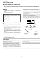
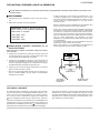
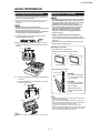
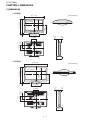
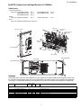
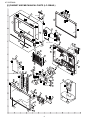
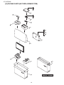
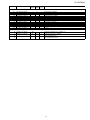
TopPage LC-32/37M44L SERVICE MANUAL No. S48J1LC32M44L LCD COLOR TELEVISION LC-32M44L LC-37M44L MODELS LC-32M44L LC-37M44L In the interests of user-safety (Required by safety regulations in some countries) the set should be restored to its original condition and only parts identical to those specified should be used. OUTLINE This model is based on the LC-32/37D44U and is changed some parts. This Service Manual covers the modifications alone. For the other points, refer to the LC-32D44U (No. SY7C1LC32D44U) and LC-37D44U (No. S18D7LC37D44U) Service Manual. CONTENTS OUTLINE AND DIFFERENCES FROM BASE MODEL OUTLINE.................................................................... i LIST OF CHANGED PARTS (LC-32M44L)................ i LIST OF CHANGED PARTS (LC-37M44L)............... ii SAFETY PRECAUTION IMPORTANT SERVICE SAFETY PRECAUTION...........................................................iii PRECAUTIONS A PRENDRE LORS DE LA REPARATION .......................................................... iv PRECAUTIONS FOR USING LEAD-FREE SOLDER ................................................................... v PRECAUTIONS IN SERVICING THE HDCPKEY ROM................................................................. vi CHAPTER 1. SPECIFICATIONS [1] SPECIFICATIONS .................................................1-1 CHAPTER 2. OPERATION MANUAL [1] OPERATION MANUAL ..........................................2-1 CHAPTER 3. DIMENSIONS [1] DIMENSIONS ........................................................3-1 Parts Guide Parts marked with " " are important for maintaining the safety of the set. Be sure to replace these parts with specified ones for maintaining the safety and performance of the set. This document has been published to be used for after sales service only. The contents are subject to change without notice. LC-32/37M44L LC-32/37M44L Service Manual OUTLINE AND DIFFERENCES FROM BASE MODEL OUTLINE This model is based on the LC-32/37D44U and is changed some parts. This Service Manual covers the modifications alone. For the other points, refer to the LC-32D44U (No. SY7C1LC32D44U) and LC-37D44U (No. S18D7LC37D44U) Service Manual. LIST OF CHANGED PARTS (LC-32M44L) Ref. No. Description LC-32D44U (No. SY7C1LC32D44U) PRINTED WIRING BOARD ASSEMBLIES R/C, LED Unit DUNTKE264FM02 KEY Unit DUNTKE266FM02 MAIN Unit DUNTKE450FM01 POWER/INVERTER Unit RUNTKA397WJQZ LC-32M44L (No. S48J1LC32M44L) Note ← ← DUNTKE450FM03 RUNTKA419WJQZ Some parts changed — Some parts changed — R1LK315T3GW20Z R1LK315T3GW30Z — R/C, LED Unit Q102 Transistor Q103 Transistor Q104 Transistor Q106 Transistor Q107 Transistor VS2SC3928AR-1Y VS2SC3928AR-1Y VS2SC3928AR-1Y VS2SC3928AR-1Y VS2SC3928AR-1Y VSKTC3875SG-1Y VSKTC3875SG-1Y VSKTC3875SG-1Y VSKTC3875SG-1Y VSKTC3875SG-1Y Change Change Change Change Change MAIN Unit D1306 D9003 IC1604 P2001 P9202 P9301 Q509 Q510 Q515 Q516 Q517 Q518 Q519 Q520 Q521 Q522 Q523 Q524 Q1101 Q1102 Q1307 Q2001 Q5414 Q9301 R9209 VHPGPFSV51T-1 RH-EX1234CEZZY VHiSii9185+-1Q QPLGN0060CEZZY QPLGNA144WJZZY QCNCWA562WJQZY VS2SA1530AR-1Y VS2SC3928AR-1Y VS2SA1530AR-1Y VS2SA1530AR-1Y VS2SA1530AR-1Y VS2SA1530AR-1Y VS2SA1530AR-1Y VS2SA1530AR-1Y VS2SA1530AR-1Y VS2SA1530AR-1Y VS2SA1530AR-1Y VS2SA1530AR-1Y VS2SC3928AR-1Y VS2SC3928AR-1Y VS2SA1530AR-1Y VSKRC404E++-1Y VS2SA1530AR-1Y VS2SA1530AR-1Y VRS-CZ1JF470JY VHPGPFSV51V-1 — VHiSii9185A-1Q — — — VSKTA1504SG-1Y VSKTC3875SG-1Y VSKTA1504SG-1Y VSKTA1504SG-1Y VSKTA1504SG-1Y VSKTA1504SG-1Y VSKTA1504SG-1Y VSKTA1504SG-1Y VSKTA1504SG-1Y VSKTA1504SG-1Y VSKTA1504SG-1Y VSKTA1504SG-1Y VSKTC3875SG-1Y VSKTC3875SG-1Y VSKTA1504SG-1Y — VSKTA1504SG-1Y VSKTA1504SG-1Y — Change Delete Change Delete Delete Delete Change Change Change Change Change Change Change Change Change Change Change Change Change Change Change Delete Change Change Delete LCD PANEL LCD Panel Module Unit Photo Diode Zener Diode IC Plug Plug Plug Transistor Transistor Transistor Transistor Transistor Transistor Transistor Transistor Transistor Transistor Transistor Transistor Transistor Transistor Transistor Transistor Transistor Transistor Resistor CABINET AND MECHANICAL PARTS Please refer to a Parts list PACKING PARTS AND ACCESSORIES Please refer to a Parts list i LC-32/37M44L LIST OF CHANGED PARTS (LC-37M44L) Ref. No. Description LC-37D44U (No. S18D7LC37D44U) PRINTED WIRING BOARD ASSEMBLIES R/C, LED Unit DUNTKE264FM02 KEY Unit DUNTKE266FM02 MAIN Unit DUNTKE450FM01 POWER Unit RDENCA272WJQZ INVERTER Unit RUNTKA418WJQZ LC-37M44L (No. S48J1LC32M44L) ← ← DUNTKE450FM03 RDENCA270WJQZ ← Note Some parts changed — Some parts changed — — LCD PANEL LCD Panel Module Unit ← R1LK370T3GW20Z — R/C, LED Unit Q102 Transistor Q103 Transistor Q104 Transistor Q106 Transistor Q107 Transistor VS2SC3928AR-1Y VS2SC3928AR-1Y VS2SC3928AR-1Y VS2SC3928AR-1Y VS2SC3928AR-1Y VSKTC3875SG-1Y VSKTC3875SG-1Y VSKTC3875SG-1Y VSKTC3875SG-1Y VSKTC3875SG-1Y Change Change Change Change Change MAIN Unit D1306 D9003 IC1604 P2001 P9202 P9301 Q509 Q510 Q515 Q516 Q517 Q518 Q519 Q520 Q521 Q522 Q523 Q524 Q1101 Q1102 Q1307 Q2001 Q5414 Q9301 R9209 VHPGPFSV51T-1 RH-EX1234CEZZY VHiSii9185+-1Q QPLGN0060CEZZY QPLGNA144WJZZY QCNCWA562WJQZY VS2SA1530AR-1Y VS2SC3928AR-1Y VS2SA1530AR-1Y VS2SA1530AR-1Y VS2SA1530AR-1Y VS2SA1530AR-1Y VS2SA1530AR-1Y VS2SA1530AR-1Y VS2SA1530AR-1Y VS2SA1530AR-1Y VS2SA1530AR-1Y VS2SA1530AR-1Y VS2SC3928AR-1Y VS2SC3928AR-1Y VS2SA1530AR-1Y VSKRC404E++-1Y VS2SA1530AR-1Y VS2SA1530AR-1Y VRS-CZ1JF470JY VHPGPFSV51V-1 — VHiSii9185A-1Q — — — VSKTA1504SG-1Y VSKTC3875SG-1Y VSKTA1504SG-1Y VSKTA1504SG-1Y VSKTA1504SG-1Y VSKTA1504SG-1Y VSKTA1504SG-1Y VSKTA1504SG-1Y VSKTA1504SG-1Y VSKTA1504SG-1Y VSKTA1504SG-1Y VSKTA1504SG-1Y VSKTC3875SG-1Y VSKTC3875SG-1Y VSKTA1504SG-1Y — VSKTA1504SG-1Y VSKTA1504SG-1Y — Change Delete Change Delete Delete Delete Change Change Change Change Change Change Change Change Change Change Change Change Change Change Change Delete Change Change Delete Photo Diode Zener Diode IC Plug Plug Plug Transistor Transistor Transistor Transistor Transistor Transistor Transistor Transistor Transistor Transistor Transistor Transistor Transistor Transistor Transistor Transistor Transistor Transistor Resistor CABINET AND MECHANICAL PARTS Please refer to a Parts list PACKING PARTS AND ACCESSORIES Please refer to a Parts list ii LC-32/37M44L LC-32/37M44L SAFETY PRECAUTION Service Manual IMPORTANT SERVICE SAFETY PRECAUTION Service work should be performed only by qualified service technicians who are thoroughly familiar with all safety checks and the servicing guidelines which follow: WARNING • 1. For continued safety, no modification of any circuit should be attempted. Use an AC voltmeter having with 5000 ohm per volt, or higher, sensitivity or measure the AC voltage drop across the resistor. • Connect the resistor connection to all exposed metal parts having a return to the chassis (antenna, metal cabinet, screw heads, knobs and control shafts, escutcheon, etc.) and measure the AC voltage drop across the resistor. 2. Disconnect AC power before servicing. All checks must be repeated with the AC cord plug connection reversed. (If necessary, a nonpolarized adaptor plug must be used only for the purpose of completing these checks.) C A U T I O N : F O R C O N T I N U E D PROTECTION AGAINST A RISK OF FIRE REPLACE ONLY WITH SAME TYPE FUSE. Any reading of 0.75 Vrms (this corresponds to 0.5 mA rms AC.) or more is excessive and indicates a potential shock hazard which must be corrected before returning the monitor to the owner. F7101 (250V 6.3A) F7102 (250V 1A) F7103 (250V 6.3A) DVM AC SCALE BEFORE RETURNING THE RECEIVER (Fire & Shock Hazard) 1.5k ohm 10W Before returning the receiver to the user, perform the following safety checks: 3. Inspect all lead dress to make certain that leads are not pinched, and check that hardware is not lodged between the chassis and other metal parts in the receiver. 0.15 µF TEST PROBE 4. Inspect all protective devices such as non-metallic control knobs, insulation materials, cabinet backs, adjustment and compartment covers or shields, isolation resistor-capacitor networks, mechanical insulators, etc. 5. To be sure that no shock hazard exists, check for leakage current in the following manner. • Plug the AC cord directly into a 110-240 volt 50/60Hz AC outlet. • Using two clip leads, connect a 1.5k ohm, 10 watt resistor paralleled by a 0.15µF capacitor in series with all exposed metal cabinet parts and a known earth ground, such as electrical conduit or electrical ground connected to an earth ground. TO EXPOSED METAL PARTS CONNECT TO KNOWN EARTH GROUND /////////////////////////////////////////////////////////////////////////////////////////////////////////////////////////////////////////////////////////////////////////////////////////////////////////////////////////////////////////// SAFETY NOTICE Many electrical and mechanical parts in LCD color television have special safety-related characteristics. For continued protection, replacement parts must be identical to those used in the original circuit. These characteristics are often not evident from visual inspection, nor can protection afforded by them be necessarily increased by using replacement components rated for higher voltage, wattage, etc. The use of a substitute replacement parts which do not have the same safety characteristics as the factory recommended replacement parts shown in this service manual, may create shock, fire or other hazards. Replacement parts which have these special safety characteristics are identified in this manual; electrical components having such features are identified by " " and shaded areas in the Replacement Parts List and Schematic Diagrams. /////////////////////////////////////////////////////////////////////////////////////////////////////////////////////////////////////////////////////////////////////////////////////////////////////////////////////////////////////////// iii LC-32/37M44L PRECAUTIONS A PRENDRE LORS DE LA REPARATION Ne peut effectuer la réparation qu' un technicien spécialisé qui s'est parfaitement accoutumé à toute vérification de sécurité et aux conseils suivants. AVERTISSEMENT • A l'aide de deux fils à pinces, brancher une résistance de 1.5 kΩ 10 watts en parallèle avec un condensateur de 0.15µF en série avec toutes les pièces métalliques exposées du coffret et une terre connue comme une conduite électrique ou une prise de terre branchée à la terre. 1. N'entreprendre aucune modification de tout circuit. C'est dangereux. 2. Débrancher le récepteur avant toute réparation. • Utiliser un voltmètre CA d'une sensibilité d'au moins 5000Ω/V pour mesurer la chute de tension en travers de la résistance. PRECAUTION: POUR LA PROTECTION CONTINUE CONTRE LES RISQUES D'INCENDIE, REMPLACER LE FUSIBLE • Toucher avec la sonde d'essai les pièces métalliques exposées qui présentent une voie de retour au châssis (antenne, coffret métallique, tête des vis, arbres de commande et des boutons, écusson, etc.) et mesurer la chute de tension CA en-travers de la résistance. Toutes les vérifications doivent être refaites après avoir inversé la fiche du cordon d'alimentation. (Si nécessaire, une prise d'adpatation non polarisée peut être utilisée dans le but de terminer ces vérifications.) La tension de pointe mesurèe ne doit pas dépasser 0.75V (correspondante au courant CA de pointe de 0.5mA). Dans le cas contraire, il y a une possibilité de choc électrique qui doit être supprimée avant de rendre le récepteur au client. F7101 (250V 6.3A) F7102 (250V 1A) F7103 (250V 6.3A) VERIFICATIONS CONTRE L'INCEN-DIE ET LE CHOC ELECTRIQUE Avant de rendre le récepteur à l'utilisateur, effectuer les vérifications suivantes. 3. Inspecter tous les faisceaux de câbles pour s'assurer que les fils ne soient pas pincés ou qu'un outil ne soit pas placé entre le châssis et les autres pièces métalliques du récepteur. DVM ECHELLE CA 4. Inspecter tous les dispositifs de protection comme les boutons de commande non-métalliques, les isolants, le dos du coffret, les couvercles ou blindages de réglage et de compartiment, les réseaux de résistancecapacité, les isolateurs mécaniques, etc. 1.5k ohm 10W 5. S'assurer qu'il n'y ait pas de danger d'électrocution en vérifiant la fuite de courant, de la facon suivante: • 0.15 µF SONDE D'ESSAI Brancher le cordon d'alimentation directem-ent à une prise de courant de 110-240V 50/60Hz. (Ne pas utiliser de transformateur d'isolation pour cet essai). AUX PIECES METALLIQUES EXPOSEES BRANCHER A UNE TERRE CONNUE ///////////////////////////////////////////////////////////////////////////////////////////////////////////////////////////////////////////////////////////////////////////////////////////////////////////////////////////////////////////// AVIS POUR LA SECURITE Pour assurer la protection, ces pièces doivent être identiques à celles utilisées dans le circuit d'origine. L'utilisation de pièces qui n'ont pas les mêmes caractéristiques que les pièces recommandées par l'usine, indiquées dans ce manuel, peut provoquer des électrocutions, incendies, radiations X ou autres accidents. De nombreuses pièces, électriques et mécaniques, dans les téléviseur ACL présentent des caractéristiques spéciales relatives à la sécurité, qui ne sont souvent pas évidentes à vue. Le degré de protection ne peut pas être nécessairement augmentée en utilisant des pièces de remplacement étalonnées pour haute tension, puissance, etc. Les pièces de remplacement qui présentent ces caractéristiques sont identifiées dans ce manuel; les pièces électriques qui présentent ces particularités sont identifiées par la marque " " et hachurées dans la liste des pièces de remplacement et les diagrammes schématiques. ///////////////////////////////////////////////////////////////////////////////////////////////////////////////////////////////////////////////////////////////////////////////////////////////////////////////////////////////////////////// iv LC-32/37M44L PRECAUTIONS FOR USING LEAD-FREE SOLDER Employing lead-free solder • “PWBs” of this model employs lead-free solder. The LF symbol indicates lead-free solder, and is attached on the PWBs and service manuals. The alphabetical character following LF shows the type of lead-free solder. Example: Indicates lead-free solder of tin, silver and copper. Indicates lead-free solder of tin, silver and copper. Using lead-free wire solder • When fixing the PWB soldered with the lead-free solder, apply lead-free wire solder. Repairing with conventional lead wire solder may cause damage or accident due to cracks. As the melting point of lead-free solder (Sn-Ag-Cu) is higher than the lead wire solder by 40 °C, we recommend you to use a dedicated soldering bit, if you are not familiar with how to obtain lead-free wire solder or soldering bit, contact our service station or service branch in your area. Soldering • As the melting point of lead-free solder (Sn-Ag-Cu) is about 220 °C which is higher than the conventional lead solder by 40 °C, and as it has poor solder wettability, you may be apt to keep the soldering bit in contact with the PWB for extended period of time. However, Since the land may be peeled off or the maximum heat-resistance temperature of parts may be exceeded, remove the bit from the PWB as soon as you confirm the steady soldering condition. Lead-free solder contains more tin, and the end of the soldering bit may be easily corroded. Make sure to turn on and off the power of the bit as required. If a different type of solder stays on the tip of the soldering bit, it is alloyed with lead-free solder. Clean the bit after every use of it. When the tip of the soldering bit is blackened during use, file it with steel wool or fine sandpaper. • Be careful when replacing parts with polarity indication on the PWB silk. Lead-free wire solder for servicing PARTS CODE ZHNDAi123250E ZHNDAi126500E ZHNDAi12801KE PRICE RANK BL BK BM PART DELIVERY J J J DESCRIPTION φ0.3mm 250g (1roll) φ0.6mm 500g (1roll) φ1.0mm 1kg (1roll) v LC-32/37M44L PRECAUTIONS IN SERVICING THE HDCP-KEY ROM Applied part: HDCP-KEY ROM IC8451 RH-IXC373WJQZY (updated ROM) The HDCP-KEY ROM shall be protected and managed for its information inside. In servicing this ROM, therefore, take the following information protection/management measures. 1) When disposing of the component parts and PWBs, destruct the IC itself in a proper way. (For repairing or replacing the component parts and PWBs as well as clearing those in stock) 2) In storing the component parts, protect and manage them against theft and disclosure. (For storing the service parts, service units, etc.) vi LC-32/37M44L CHAPTER 1. SPECIFICATIONS LC-32/37M44L Service Manual [1] SPECIFICATIONS Item Model: LC-32M44L LCD panel 32" screen size class Advanced Super View & BLACK TFT LCD (Diagonal Measurement : 311/ 2") Resolution 1,049,088 pixels (1,366 TV-standard (CCIR) TV Function Receiving Channel American TV Standard ATSC/NTSC System VHF 2-13ch, UHF 14-69ch CATV 1-135ch (non-scrambled channel only) Digital Terrestrial 2-69ch Broadcast (8VSB) Audio multiplex Audio out 1-135ch (non-scrambled channel only) BTSC System 10W Rear 37" screen size class Advanced Super View & BLACK TFT LCD (Diagonal Measurement : 37") 768) VHF/UHF Digital cable* (64/256 QAM) Terminals Model: LC-37M44L 2 INPUT 1 AV in, COMPONENT in INPUT 2 AV in, S-VIDEO in INPUT 3 COMPONENT in INPUT 4 HDMI in with HDCP INPUT 5 Audio in, HDMI in with HDCP INPUT 6 15-pin mini D-sub female connector, Audio in (Ø 3.5 mm jack) ANT/CABLE 75 Unbalance, F Type DIGITAL AUDIO OUTPUT Optical Digital audio output OUTPUT Audio out SERVICE Software update 1 for Analog (VHF/UHF/CATV) and Digital (AIR/CABLE) 1 (PCM/Dolby Digital) OSD language English/French/Spanish Power Requirement AC 110-240 V, 50/60 Hz Power Consumption 140 W (0.9 W Standby) 172 W (0.9 W Standby) TV + stand 29.8 lbs./13.5 kg 35.3 lbs./16.0 kg TV only 25.4 lbs./11.5 kg Weight Dimension (W H D) 30.9 lbs./14.0 kg TV + stand 9 30 / 16 41 22 / 64 9 / 16 inch 35 19/ 32 25 3/ 32 9 1/ 16 inch TV only 30 9/ 16 20 19/ 32 3 45/ 64 inch 35 19/ 32 23 1/ 32 3 3/ 4 inch Operating temperature 32°F to 1 104°F (0°C to 40°C) * Emergency alert messages via Cable are unreceivable. As part of policy of continuous improvement, SHARP reserves the right to make design and specification changes for product improvement without prior notice. The performance specification figures indicated are nominal values of production units. There may be some deviations from these values in individual units. 1–1 LC-32/37M44L CHAPTER 2. OPERATION MANUAL LC-32/37M44L Service Manual [1] OPERATION MANUAL Part Names TV (Front) Remote control sensor OPC sensor OPC indicator SLEEP indicator POWER indicator TV (Top/Rear) Channel buttons (CH / ) Volume buttons (VOL / ) MENU button INPUT button POWER button AC INPUT terminal AUDIO OUTPUT terminals DIGITAL AUDIO OUTPUT terminal INPUT 6 terminals (PC-IN) INPUT 5 terminals (HDMI) INPUT 4 terminal (HDMI) INPUT 1 terminals SERVICE terminal INPUT 2 terminals Antenna/Cable in INPUT 3 terminals The illustrations in this operation manual are for explanation purposes and may vary slightly from the actual operations. The examples used throughout this manual are based on the LC-32M44L model. 2–1 LC-32/37M44L Part Names Remote Control Unit 1 POWER: Switch the TV power on or enters standby. 2 CC: Display captions from a closed-caption source. 3 AUDIO: Selects the MTS/SAP or the audio mode during multi-channel audio broadcasts. 14 4 0_9: Set the channel. 15 6 FLASHBACK: Return to the previous channel or external input mode. 7 VIEW MODE: Select the screen size. 8 FREEZE: Set the still image. Press again to return to normal screen. 9 / / / screen. 11 12 1 2 3 4 13 16 5 6 7 8 17 18 19 20 (DOT): , ENTER: Select a desired item on the 10 EXIT: Turn off the menu screen. 11 DISPLAY: Display the channel information. 9 10 5 12 SLEEP: Set the sleep timer. 21 22 13 AV MODE: Select an audio or video setting. (When the input source is TV, INPUT 1, 2 or 3: STANDARD, MOVIE, GAME, USER, DYNAMIC (Fixed), DYNAMIC. When the input source is INPUT 4, 5 or 6: STANDARD, MOVIE, GAME, PC, USER, DYNAMIC (Fixed), DYNAMIC) 14 MUTE: Mute the sound. 15 VOL / : Set the volume. 16 CH : Select the channel. / 17 ENT: Jumps to a channel after selecting with the 0_9 buttons. 18 INPUT: Select a TV input source. (TV, INPUT 1, INPUT 2, INPUT 3, INPUT 4, INPUT 5, INPUT 6) 19 PC: Quickly access to PC mode. 20 MENU: Display the menu screen. 21 RETURN: Return to the previous menu screen. 22 FAVORITE CH A, B, C, D: Select 4 preset favorite channels in 4 different categories. While watching, you can toggle the selected channels by pressing A, B, C and D. When using the remote control unit, point it at the TV. 2–2 LC-32/37M44L QUICK REFERENCE Attaching/Detaching the Stand Setting the TV on the Wall Before attaching (or detaching) the stand, unplug the AC cord from the AC INPUT terminal. Before performing work spread cushioning over the base area to lay the TV on. This will prevent it from being damaged. CAUTION This TV should be mounted on the wall only with the AN-37AG5 (SHARP) wall mount bracket. The use of other wall mount brackets may result in an unstable installation and may cause serious injuries. Installing the TV requires special skill that should only be performed by qualified service personnel. Customers should not attempt to do the work themselves. SHARP bears no responsibility for improper mounting or mounting that results in accident or injury. CAUTION Attach the stand in the correct direction. Do not remove the stand from the TV unless using an optional wall mount bracket to mount it. Be sure to follow the instructions. Incorrect installation of the stand may result in the TV falling over. Using an optional bracket to mount the TV You can ask a qualified service professional about using an optional AN-37AG5 bracket to mount the TV to the wall. Carefully read the instructions that come with the bracket before beginning work. 1 Confirm that there are 9 screws and a hex key supplied with the stand unit. 2 Attach the supporting post for the stand unit onto the base using the box for the stand unit as shown below. Hanging on the wall AN-37AG5 wall mount bracket. (See the bracket instructions for details.) 3 Hex key Screws 2 Vertical mounting About setting the TV angle 1 0/5/10/15/20q 3 Ԙ Insert the stand into the openings on the bottom of the TV. LC-32M44L The center of the display: 11 / 64 inch (4.0 mm) under the "A" position. LC-37M44L The center of the display: 1 / 4 inch (6.0 mm) above the "A" position. ԙ Insert and tighten the 4 screws into the 4 holes on the rear of the TV. Hex key Angular mounting 2 Refer to the operation manual of AN-37AG5 for details. Screws Detach the cable clamp on the rear of the TV when using the optional mount bracket. Due to the terminal configuration on this TV, when you wall-mount this model, make sure there is enough space between the wall and the TV for the cables. To use this TV mounted on a wall, first remove the adhesive tape at the 4 locations on the rear of the TV, and then use the screws supplied with the wall mount bracket to secure the bracket to the rear of the TV. Soft cushion 1 To detach the stand, perform the steps in reverse order. 2–3 LC-32/37M44L Appendix Troubleshooting Problem Possible Solution No power Check if you pressed POWER on the remote control unit. If the indicator on the TV does not light up, press POWER on the TV. Is the AC cord disconnected? Has the power been turned on? Unit cannot be operated. External influences such as lightning, static electricity, may cause improper operation. In this case, operate the unit after first turning off the power of the TV or unplugging the AC cord and replugging it in after 1 or 2 minutes. Remote control unit does not operate. Are batteries inserted with polarity ( , ) aligned? Are batteries worn out? (Replace with new batteries.) Are you using it under strong or fluorescent lighting? Is a fluorescent light illuminated near the remote control sensor? Picture is cut off/with sidebar screen. Is the image position correct? Are screen mode adjustments such as picture size made correctly? Strange color, light color, or color misalignment Adjust the picture tone. Is the room too bright? The picture may look dark in a room that is too bright. Check the input signal setting. Power is suddenly turned off. Is the sleep timer set? Check the power control settings. The unit's internal temperature has increased. Remove any objects blocking vent or clean. No picture Is connection to other components correct? Is correct input signal source selected after connection? Is the correct input selected? Is picture adjustment correct? Is "On" selected in "Audio Only"? Is a non-compatible signal being input? No sound Is the volume too low? Is "Variable" selected in "Output Select"? Have you pressed MUTE on the remote control unit? The TV sometimes makes a cracking sound. This is not a malfunction. This happens when the cabinet slightly expands and contracts according to change in temperature. This does not affect the TV's performance. Troubleshooting-Digital Broadcasting The error message about reception of broadcast The example of an error message displayed on a screen Error code Possible Solution Failed to receive broadcast. E202 Check the antenna cable. Check that the antenna is correctly setup. No broadcast now. E203 Check the broadcast time in the program guide. Cautions regarding use in high and low temperature environments When the unit is used in a low temperature space (e.g. room, office), the picture may leave trails or appear slightly delayed. This is not a malfunction, and the unit will recover when the temperature returns to normal. Do not leave the unit in a hot or cold location. Also, do not leave the unit in a location exposed to direct sunlight or near a heater, as this may cause the cabinet to deform and the Liquid Crystal panel to malfunction. Storage temperature: 4°F to 140°F ( 20°C to 60°C) 2–4 LC-32/37M44L PC Compatibility Chart It is necessary to set the PC correctly to display XGA and WXGA signal. PC Resolution 720 x 400 Horizontal Frequency 31.5 kHz 31.5 kHz VGA 640 x 480 37.9 kHz 37.5 kHz 35.1 kHz 37.9 kHz SVGA 800 x 600 PC 48.1 kHz 46.9 kHz 48.4 kHz XGA 1024 x 768 56.5 kHz 60.0 kHz WXGA 1360 x 768 47.7 kHz *These 3 formats are not supported by the analog RGB terminal. Vertical Frequency 70 Hz 60 Hz 72 Hz 75 Hz 56 Hz 60 Hz 72 Hz 75 Hz 60 Hz 70 Hz 75 Hz 60 Hz DDC is a registered trademark of Video Electronics Standards Association. VGA and XGA are registered trademarks of International Business Machines Corp. 2–5 VESA Standard O O O O O O O O O O O * * * LC-32/37M44L CHAPTER 3. DIMENSIONS LC-32/37M44L Service Manual [1] DIMENSIONS LC-32M44L Unit: inch (mm) 13 5/ 64 (332) 27 17/ 32 (699.2) 15 1/ 2 (393.8) 20 19/ 32 (523) 2 1/ 16 (52) 22 41/ 64 (575) 30 9/ 16 (776) 15 27/ 32 (402) 2 59/ 64 (74) 3 45/ 64 (94) 7 7/ 8 (200) 4 11/ 32 (110) 7 7/ 8 (200) 9 1/ 16 (230) LC-37M44L 35 19/ 32 (904) Unit: inch (mm) 14 29/ 64 (367) 18 17/ 64 (463.8) 23 1/ 32 (585) 2 1/ 16 (52) 25 3/ 32 (637) 32 15/ 32 (824.4) 15 27/ 32 (402) 2 25/ 32 (71) 3 3/ 4 (95) 7 7/ 8 (200) 3 61/ 64 (100) 7 7/ 8 (200) 9 1/ 16 (230) 3–1 LC-32/37M44L PartsGuide PARTS GUIDE No. S48J1LC32M44L Note: The reference numbers on the PWB are arranged in alphabetical order. MODELS LC-32M44L LC-37M44L CONTENTS [1] PRINTED WIRING BOARD ASSEMBLIES [9] SUPPLIED ACCESSORIES [2] LCD PANEL (NOTE: THE PARTS HERE SHOWN ARE SUPPLIED AS AN ASSEMBLY BUT NOT INDEPENDENTLY.) [10] PACKING PARTS (NOT REPLACEMENT ITEM) [11] SERVICE JIG (USE FOR SERVICING) [3] DUNTKE264FM02 (R/C, LED Unit) [4] DUNTKE450FM03 (MAIN Unit) [5] NOTE (Conductive cloth tape/Gasket) (LC-32M44L) [6] CABINET AND MECHANICAL PARTS (LC-32M44L) [7] NOTE (Conductive cloth tape/Gasket) (LC-37M44L) [8] CABINET AND MECHANICAL PARTS (LC-37M44L) Parts marked with " " are important for maintaining the safety of the set. Be sure to replace these parts with specified ones for maintaining the safety and performance of the set. This document has been published to be used for after sales service only. The contents are subject to change without notice. LC-32/37M44L NO. PARTS CODE PRICE NEW RANK MARK DESCRIPTION PART DELIVERY [1] PRINTED WIRING BOARD ASSEMBLIES N N N N N N DUNTKE264FM02 DUNTKE266FM02 DUNTKE450FM03 RDENCA270WJQZ RUNTKA418WJQZ RUNTKA419WJQZ AP AG CD BQ BN BU N N N N X X R X X X R/C, LED Unit KEY Unit MAIN Unit POWER Unit (LC-37M44L) INVERTER Unit (LC-37M44L) POWER/INVERTER Unit (LC-32M44L) [2] LCD PANEL (NOTE: THE PARTS HERE SHOWN ARE SUPPLIED AS AN ASSEMBLY BUT NOT INDEPENDENTLY.) N N R1LK315T3GW30Z R1LK370T3GW20Z CW EC N N J J 32"LCD Panel Module Unit (LC-32M44L) 37"LCD Panel Module Unit (LC-37M44L) J J J J J Transistor Transistor Transistor Transistor Transistor R J R J R R R R R R R R R R J J R R R Photo Diode IC, SII9185ACTU Transistor Transistor Transistor Transistor Transistor Transistor Transistor Transistor Transistor Transistor Transistor Transistor Transistor Transistor Transistor Transistor Transistor [3] DUNTKE264FM02 (R/C, LED Unit) Q102 Q103 Q104 Q106 Q107 VSKTC3875SG-1Y VSKTC3875SG-1Y VSKTC3875SG-1Y VSKTC3875SG-1Y VSKTC3875SG-1Y AB AB AB AB AB [4] DUNTKE450FM03 (MAIN Unit) D1306 IC1604 Q509 Q510 Q515 Q516 Q517 Q518 Q519 Q520 Q521 Q522 Q523 Q524 Q1101 Q1102 Q1307 Q5414 Q9301 VHPGPFSV51V-1 VHISII9185A-1Q VSKTA1504SG-1Y VSKTC3875SG-1Y VSKTA1504SG-1Y VSKTA1504SG-1Y VSKTA1504SG-1Y VSKTA1504SG-1Y VSKTA1504SG-1Y VSKTA1504SG-1Y VSKTA1504SG-1Y VSKTA1504SG-1Y VSKTA1504SG-1Y VSKTA1504SG-1Y VSKTC3875SG-1Y VSKTC3875SG-1Y VSKTA1504SG-1Y VSKTA1504SG-1Y VSKTA1504SG-1Y AG AN AA AB AA AA AA AA AA AA AA AA AA AA AB AB AA AA AA N N N N N N N N N N N N N N N 2 LC-32/37M44L [5] NOTE (Conductive cloth tape/Gasket) (LC-32M44L) Added parts Conductive Cloth Tape ˴Parts code: ԘPSLDMB359WJZZ Q'ty 1 ԙPSLDMB360WJZZ ԚQEARZA123WJZZ Q'ty 3 ԛPSLDMB361WJZZ ԜPSLDMB362WJZZ Q'ty 2 Gasket ˴Parts code: ԝPMLT-A533WJZZ Q'ty 1 ԞPMLT-A534WJZZ Bond ˴Parts code: ԟZSLCN-098P2KE (One 150g tube) Q'ty 2 Q'ty 2 Q'ty 1 Apply bond to 1 location. Back Light Chassis 8 Apply bond to 1 location. 8 1 8 Apply bond to 1 location. 3 2 2 8 Apply bond to 1 location. LCD Panel Module 3 RA wire SP wire Main Shield 3 Main PWB Holder Main PWB Holder MAIN Unit 5 4 7 6 4 5 Attention When peeling off the conductive cloth tape/gasket for repair, please use the NEW conductive cloth tape/gasket. (When using the conductive cloth tape/gasket again, keep in mind the decrease in the adhesive power of the conductive cloth tape/gasket. The purpose of using the NEW conductive cloth tape/gasket is to prevent the conductive cloth tape/gasket from peeling off.) NO. PARTS CODE PRICE NEW RANK MARK DESCRIPTION PART DELIVERY [5] NOTE (Conductive cloth tape/Gasket) (LC-32M44L) 1 2 3 4 5 6 7 8 PSLDMB359WJZZ PSLDMB360WJZZ QEARZA123WJZZ PSLDMB361WJZZ PSLDMB362WJZZ PMLT-A533WJZZ PMLT-A534WJZZ ZSLCN-098P2KE AG AE AD AC AC AD AC BH N N N N N N X X X X X X X J Conductive Cloth Tape Conductive Cloth Tape, x2 Conductive Cloth Tape, x3 Conductive Cloth Tape, x2 Conductive Cloth Tape, x2 Gasket Gasket One 150g tube 3 LC-32/37M44L [6] CABINET AND MECHANICAL PARTS (LC-32M44L) 7 37 1 1-6 36 30 KEY Unit 37 36 3 1-1 1-5 32 31 1-6 1-8 1-5 38 35 1-7 38 1-4 46 R/C, LED Unit 1-3 1-7 1-2 6 42 2-2 27 49 48 45 49 20 40 42 26 2-1 50 33 12 45 45 29 10 25 22 51 28 21 46 23 51 14 5 45 46 43 15 19 21 44 14 45 9 17 43 POWER/INVERTER Unit 43 41 2 45 34 39 47 47-2 17 24 12 MAIN Unit 47-3 50 13 45 11 43 45 35 4 18 53 45 10 47-1 47-3 8 45 11 16 45 35 4 LC-32/37M44L NO. PARTS CODE PRICE NEW RANK MARK DESCRIPTION PART DELIVERY [6] CABINET AND MECHANICAL PARTS (LC-32M44L) 1 1-1 1-2 1-3 1-4 1-5 1-6 1-7 1-8 2 2-1 2-2 3 4 5 6 7 8 9 10 11 12 13 14 15 16 17 18 19 20 21 22 23 24 25 26 27 28 29 30 31 32 33 34 35 36 37 38 39 40 41 42 43 44 45 46 47 47-1 47-2 47-3 48 49 50 51 52 53 CCABAB985WJ34 Not Available Not Available Not Available HPNLSA172WJKA PSPAHB406WJZZ PSPAHB407WJZZ Not Available XJPSN30P08XS0 CCABBB237WJK1 Not Available HINDPC686WJSA R1LK315T3GW30Z GCOVAC612WJ3A HINDPB715WJSA HINDPC873WJSA JBTN-A718WJ3A LANGKB343WJZZ LANGKB346WJFW LANGKB364WJFW LANGKB365WJFW LANGTA476WJZZ LHLDWA133WJKZ LHLDWA143WJKZ LHLDWA151WJKZ LHLDWA175WJUZ LHLDZA928WJ3Z LHLDZA933WJKZ LHLDZA934WJKZ NSFTZ0134CEFW PCLICA004WJKZ PMLT-A534WJZZ PMLT-A533WJZZ PRDARA495WJFW PRDARA510WJFW PSLDMB275WJZZ PSPAKA237WJ00 PSPAZB086WJKZ PSPAZA917WJKZ QCNW-G724WJQZ QCNW-G725WJQZ QCNW-H283WJPZ QCNW-G727WJQZ QCNW-G728WJQZ QEARZA123WJZZ QPWBME512WJPZ RCORFA061WJZZ RSP-ZA310WJZZ Not Available XBPS830P06000 XEBS930P10000 XEBS940P16000 XEBSN40P10000 XHPS730P16WS0 XHPS830P06WS0 XHPS830P10WS0 CDAI-A441WJ03 Not Available Not Available Not Available PSLDMB359WJZZ PSLDMB360WJZZ PSLDMB361WJZZ PSLDMB362WJZZ ZSLCN-098P2KE TLABK0023TAZZ BM AR AC AC AA BH AG CW AK AF AE AF AR AH AC AC AQ AC AC AB AC AG AB AB AD AC AC AD AH AR AQ AA AD AH AF AK AL AK AG AD AN AG AQ AA AA AB AB AB AA AB BF AG AE AC AC BH AA N N N N N N N N N N N N N N N N N N N N N N N N N N N N N N N N N N N N N N N N N N N N X X X X J X X J X X X X X X X X X J J J J X J J J J X X X X X X J J X X X X X X X J X J J J J J J J X X X X X J J Front Cabinet Ass'y Front Cabinet Decoration Plate (Center) LED Decoration Speaker Net Spacer, x2 Spacer, x2 SP Spacer, x2 Screw, x3 Rear Cabinet Ass'y Rear Cabinet Terminal Label 32"LCD Panel Module Unit Bottom Cover Terminal Label Model Label Operation Button Stand Fix Angle Heat Sink Fix Angle LCD Fix Angle-A, x2 LCD Fix Angle-B, x2 VESA Angle, x2 Wire Holder Wire Holder, x2 Wire Holder Wire Holder, x4 Main PWB Holder, x2 Wire Holder Wire Holder Shaft, x2 Rivet, x4 Gasket Gasket Heat Sink Heat Sink Main Shield Spacer, x4 Spacer, x2 Cool Sheet Connecting Cord (KEY - MAIN) Connecting Cord (LED - MAIN) Connecting Cord (SP - MAIN) Connecting Cord (POWER - MAIN) Connecting Cord (INV - MAIN) Conductive Cloth Tape, x3 Connecting Cord (LCD-FPC-MAIN), x2 Core, x2 Speaker (L/R), x2 No. Label Screw (for HDMI), x2 Screw (for S-Terminal) Screw (for CAB A B), x6 Screw (for CAB A Panel), x4 Screw (for MAIN PWB2), x4 Screw (for MAIN PWB), x30 Screw (for CAB B Chassis), x3/(for MAIN PWB2), x2 Stand Unit Stand Base Ass'y Stand Support Ass'y Screw (for Stand), x9 Conductive Cloth Tape Conductive Cloth Tape, x2 Conductive Cloth Tape, x2 Conductive Cloth Tape, x2 One 150g tube Tray Label 5 LC-32/37M44L [7] NOTE (Conductive cloth tape/Gasket) (LC-37M44L) Added parts Conductive Cloth Tape ˴Parts code: ԘPSLDMB359WJZZ Q'ty 1 ԚPSLDMB276WJKZ Q'ty 1 ԜQEARZA123WJZZ Q'ty 1 ԞPSLDMB362WJZZ Q'ty 2 Gasket ˴Parts code: ԟPMLT-A533WJZZ Q'ty 1 Bond ˴Parts code: ԡZSLCN-098P2KE (One 150g tube) ԙPSLDMB360WJZZ ԛPSLDMB375WJKZ ԝPSLDMB361WJZZ Q'ty 1 Q'ty 1 Q'ty 2 ԠPMLT-A534WJZZ Q'ty 1 Apply bond to 1 location. 10 10 10 1 Apply bond to 1 location. 2 RA wire Apply bond to 1 location. 3 10 4 5 Apply bond to 1 location. 10 Apply bond to 2 locations. SP wire Main Shield Main PWB Holder Main PWB Holder MAIN Unit 7 6 9 8 6 7 Attention When peeling off the conductive cloth tape/gasket for repair, please use the NEW conductive cloth tape/gasket. (When using the conductive cloth tape/gasket again, keep in mind the decrease in the adhesive power of the conductive cloth tape/gasket. The purpose of using the NEW conductive cloth tape/gasket is to prevent the conductive cloth tape/gasket from peeling off.) NO. PARTS CODE PRICE NEW RANK MARK DESCRIPTION PART DELIVERY [7] NOTE (Conductive cloth tape/Gasket) (LC-37M44L) 1 2 3 4 5 6 7 8 9 10 PSLDMB359WJZZ PSLDMB360WJZZ PSLDMB276WJKZ PSLDMB375WJKZ QEARZA123WJZZ PSLDMB361WJZZ PSLDMB362WJZZ PMLT-A533WJZZ PMLT-A534WJZZ ZSLCN-098P2KE AG AE AE AF AD AC AC AD AC BH N N N N N N N X X X X X X X X X J Conductive Cloth Tape Conductive Cloth Tape Conductive Cloth Tape Conductive Cloth Tape Conductive Cloth Tape Conductive Cloth Tape, x2 Conductive Cloth Tape, x2 Gasket Gasket One 150g tube 6 LC-32/37M44L [8] CABINET AND MECHANICAL PARTS (LC-37M44L) 7 1 1-5 45 35 36 30 KEY Unit 37 36 1-5 1-1 37 INVERTER Unit 1-5 3 1-5 32 1-7 31 1-5 1-8 38 50 1-5 1-6 38 1-4 R/C, LED Unit 49 39 1-3 6 1-6 1-2 42 2-2 27 34 51 45 13 41 2 20 45 52 42 40 26 33 53 9 12 45 46 45 10 54 22 12 19 14 14 48 21 25 15 23 54 28 45 45 46 29 14 43 21 44 17 POWER Unit 5 2-1 47 47-2 17 24 47-3 53 MAIN Unit 18 43 45 11 45 4 56 45 11 43 10 16 47-1 47-3 8 45 43 16 45 16 7 LC-32/37M44L NO. PARTS CODE PRICE NEW RANK MARK DESCRIPTION PART DELIVERY [8] CABINET AND MECHANICAL PARTS (LC-37M44L) 1 1-1 1-2 1-3 1-4 1-5 1-6 1-7 1-8 2 2-1 2-2 3 4 5 6 7 8 9 10 11 12 13 14 15 16 17 18 19 20 21 22 23 24 25 26 27 28 29 30 31 32 33 34 35 36 37 38 39 40 41 42 43 44 45 46 47 47-1 47-2 47-3 48 49 50 51 52 53 54 55 56 CCABAB986WJ34 Not Available Not Available Not Available HPNLSA173WJKA PSPAHB408WJZZ Not Available Not Available XJPSN30P08XS0 CCABBB238WJK1 Not Available HINDPC686WJSA R1LK370T3GW20Z GCOVAC612WJ3A HINDPB715WJSA HINDPC874WJSA JBTN-A718WJ3A LANGKB343WJZZ LANGKB346WJFW LANGKB366WJFW LANGKB367WJFW LANGTA478WJZZ PSLDMB359WJZZ LHLDWA143WJKZ PSPAZB598WJKZ LHLDWA175WJUZ LHLDZA928WJ3Z LHLDZA933WJKZ LHLDZA934WJKZ NSFTZ0134CEFW PCLICA004WJKZ PMLT-A534WJZZ PMLT-A533WJZZ PRDARA495WJFW PRDARA510WJFW PSLDMB275WJZZ PSPAKA237WJ00 PSPAZB086WJKZ PSPAZA917WJKZ QCNW-G729WJQZ QCNW-G730WJQZ QCNW-H284WJPZ QCNW-G732WJQZ PSLDMB360WJZZ PSPAZB202WJKZ QPWBME513WJPZ RCORFA061WJZZ RSP-ZA310WJZZ Not Available XBPS830P06000 XEBS930P10000 XEBS940P16000 XEBSN40P10000 XHPS730P16WS0 XHPS830P06WS0 XHPS830P10WS0 CDAI-A441WJ03 Not Available Not Available Not Available Not Available XBPS940P10JS0 QEARZA123WJZZ PSLDMB276WJKZ PSLDMB375WJKZ PSLDMB361WJZZ PSLDMB362WJZZ ZSLCN-098P2KE TLABK0023TAZZ BL AS AC AA BQ AG EC AK AF AE AF AR AH AD AD AR AG AC AP AC AG AB AB AD AC AC AD AH AR AQ AA AD AH AF AK AL AM AE AB AQ AG AQ AA AA AB AB AB AA AB BF AB AD AE AF AC AC BH AA N N N N N N N N N N N N N N N N N N N N N N N N N N N N N N N N N N N N N N N X X X J X X J X X X X X X X X X X J X J X J J J J X X X X X X J J X X X X X J X J X J J J J J J J X J X X X X X J J Front Cabinet Ass'y Front Cabinet Decoration Plate (Center) LED Decoration Speaker Net Spacer, x6 SP Spacer, x2 Spacer Screw, x3 Rear Cabinet Ass'y Rear Cabinet Terminal Label 37"LCD Panel Module Unit Bottom Cover Terminal Label Model Label Operation Button Stand Fix Angle Heat Sink Fix Angle LCD Fix Angle-T, x2 LCD Fix Angle-B, x2 VESA Angle, x2 Conductive Cloth Tape Wire Holder, x3 Conductive Sheet, x2 Wire Holder, x3 Main PWB Holder, x2 Wire Holder Wire Holder, x6 Shaft, x2 Rivet, x4 Gasket Gasket Heat Sink Heat Sink Main Shield Spacer, x4 Spacer, x2 Cool Sheet Connecting Cord (KEY - MAIN) Connecting Cord (LED - MAIN) Connecting Cord (SP - MAIN) Connecting Cord (POWER - MAIN) Conductive Cloth Tape Spacer (for INV PWB) Connecting Cord (LCD-FPC-MAIN), x2 Core, x2 Speaker (L/R), x2 Serial No. Label (Back) Screw (for HDMI), x2 Screw (for S-Terminal) Screw (for CAB A B), x4 Screw (for CAB A PANEL), x4 Screw (for MAIN PWB), x4 Screw (for Heat Sink), x32 Screw (for MAIN PWB2), x2 Stand Unit Stand Base Ass'y Stand Support Ass'y Screw (for Stand), x9 Serial No. Label (Side) Screw (for CAB B Chassis), x6 Conductive Cloth Tape Conductive Cloth Tape Conductive Cloth Tape Conductive Cloth Tape, x2 Conductive Cloth Tape, x2 One 150g tube Tray Label 8 LC-32/37M44L [9] SUPPLIED ACCESSORIES X1 Cable Clamp X2 X3 AC Cord Remote Control Unit Operation Manual X4 X5 X6 "AAA" Size Battery NO. PARTS CODE X7 Stand Unit PRICE NEW RANK MARK DESCRIPTION PART DELIVERY [9] SUPPLIED ACCESSORIES ! X1 X2 X3 X4 X5 X6 X7 LHLDWA173WJKZ QACCZA076WJPZ RRMCGA667WJSA TINS-D737WJZZ TINS-D738WJZZ Not Available CDAI-A441WJ03 AE AR AP AE AE BF N N N N J X X X X X Cable Clamp AC Cord Remote Control Unit Operation Manual (English) Operation Manual (Spanish) "AAA" Size Battery Stand Unit 9 LC-32/37M44L [10] PACKING PARTS (NOT REPLACEMENT ITEM) S8 S9 S7 S7 S4 S5 S6 S10 S2 S3 S7 S7 S1 10 S11 LC-32/37M44L NO. PARTS CODE PRICE NEW RANK MARK DESCRIPTION PART DELIVERY [10] PACKING PARTS (NOT REPLACEMENT ITEM) S1 S1 S2 S3 S3 S4 S5 S6 S7 S7 S8 S9 S10 S11 SPAKCE283WJZZ SPAKCE285WJZZ SPAKCE206WJZZ SPAKPB045WJZZ SPAKPB046WJZZ SPAKPB053WJZZ SPAKPB054WJZZ SPAKAA373WJZZ SPAKXB803WJZZ SPAKXB804WJZZ SSAKA0101GJZZ SSAKAA032WJZZ SSAKHA042WJZZ TLABKA009WJZZ - N N N N N N N N N - Packing Case (LC-32M44L) Packing Case (LC-37M44L) Stand Case Wrapping Paper (LC-32M44L) Wrapping Paper (LC-37M44L) Mirror Mat Sup Mirror Mat Base Cover Sheet Packing Add. (LC-32M44L) Packing Add. (LC-37M44L) Polyethylene Bag Polyethylene Bag Polyethylene Bag for Screw No. Label J Connecting Cord (80pin FFC L=1000mm), x2 MAIN to LCD Panel Unit Connecting Cord (12pin L=1000mm) MAIN to POWER Unit (PD) Connecting Cord (7pin L=1000mm) MAIN to INVERTER Unit (LB) [11] SERVICE JIG (USE FOR SERVICING) N N N N N N QCNW-C222WJQZ AW QCNW-G906WJQZ BA N J QCNW-G907WJQZ AW N J 11 LC-32/37M44L COPYRIGHT 2008 BY SHARP CORPORATION ALL RIGHTS RESERVED. No part of this publication may be reproduced, stored in a retrieval system, or transmitted in any form or by any means, electronic, mechanical, photocopying, recording, or otherwise, without prior written permission of the publisher. SHARP CORPORATION Jun. 2008 TQ2534-S MI. KD AV Systems Group CS Promotion Center Yaita, Tochigi 329-2193, Japan