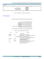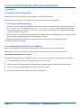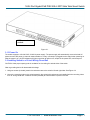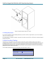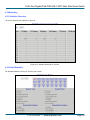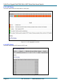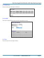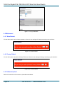
1
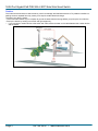
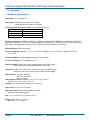
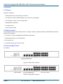
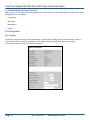
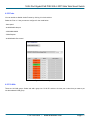
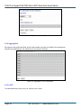
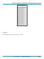
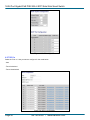
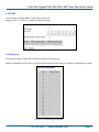
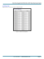
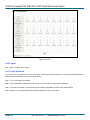
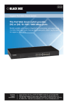
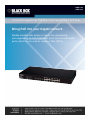
LPBG716A
LPBG724A
16-/24-Port Gigabit PoE PSE Web Smart Switch with 4 SFP Slots
Bring PoE into your Gigabit network.
Models available with sixteen or twenty-four autosensing,
auto-negotiating 10-/100-/1000-Mbps ports; four are dual-media
ports, which may be used for copper or fiber (SFPs).
16/24 Port Gigabit PoE PSE With 4 SFP Slots Web Smart Switch
Caution
Circuit devices are sensitive to static electricity, which can damage their delicate electronics. Dry weather conditions or
walking across a carpeted floor may cause you to acquire a static electrical charge.
To protect your device, always:
∞Touch the metal chassis of your computer to ground the static electrical charge before you pick up the circuit device.
∞Pick up the device by holding it on the left and right edges only.
∞ If you connect an outdoor device to the switch with cable, add an arrester on the cable between the outdoor device
and the switch.
Add an arrester between outdoor device and this switch
Page 2
724-746-5500 l www.blackbox.com
16/24 Port Gigabit PoE PSE With 4 SFP Slots Web Smart Switch
Federal Communications Commission and Industry Canada Radio Frequency Interference
Statements
This equipment generates, uses, and can radiate radio-frequency energy, and if not installed and used properly, that is, in strict
accordance with the manufacturer’s instructions, may cause interference to radio communication. It has been tested and found
to comply with the limits for a Class A computing device in accordance with the specifications in Subpart J of Part 15 of FCC
rules, which are designed to provide reasonable protection against such interference when the equipment is operated in a
commercial environment. Operation of this equipment in a residential area is likely to cause interference, in which case the user
at his own expense will be required to take whatever measures may be necessary to correct the interference.
Changes or modifications not expressly approved by the party responsible for compliance could void the user’s authority to
operate the equipment.
This digital apparatus does not exceed the Class A limits for radio noise emission from digital apparatus set out in the Radio
Interference Regulation of Industry Canada.
Le présent appareil numérique n’émet pas de bruits radioélectriques dépassant les limites applicables aux appareils
numériques de la classe A prescrites dans le Règlement sur le brouillage radioélectrique publié par Industrie Canada.
724-746-5500 l www.blackbox.com
Page 3
16/24 Port Gigabit PoE PSE With 4 SFP Slots Web Smart Switch
Normas Oficiales Mexicanas (NOM) Electrical Safety Statement
INSTRUCCIONES DE SEGURIDAD
1.
2.
3.
4.
5.
Todas las instrucciones de seguridad y operación deberán ser leídas antes de que el aparato eléctrico sea operado.
Las instrucciones de seguridad y operación deberán ser guardadas para referencia futura.
Todas las advertencias en el aparato eléctrico y en sus instrucciones de operación deben ser respetadas.
Todas las instrucciones de operación y uso deben ser seguidas.
El aparato eléctrico no deberá ser usado cerca del agua—por ejemplo, cerca de la tina de baño, lavabo, sótano
mojado o cerca de una alberca, etc..
6. El aparato eléctrico debe ser usado únicamente con carritos o pedestales que sean recomendados por el fabricante.
7. El aparato eléctrico debe ser montado a la pared o al techo sólo como sea recomendado por el fabricante.
8. Servicio—El usuario no debe intentar dar servicio al equipo eléctrico más allá a lo descrito en las instrucciones de
operación. Todo otro servicio deberá ser referido a personal de servicio calificado.
9. El aparato eléctrico debe ser situado de tal manera que su posición no interfiera su uso. La colocación del aparato
eléctrico sobre una cama, sofá, alfombra o superficie similar puede bloquea la ventilación, no se debe colocar en
libreros o gabinetes que impidan el flujo de aire por los orificios de ventilación.
10. El equipo eléctrico deber ser situado fuera del alcance de fuentes de calor como radiadores, registros de calor,
estufas u otros aparatos (incluyendo amplificadores) que producen calor.
11. El aparato eléctrico deberá ser connectado a una fuente de poder sólo del tipo descrito en el instructivo de
operación,
o como se indique en el aparato.
12. Precaución debe ser tomada de tal manera que la tierra fisica y la polarización del equipo no sea eliminada.
13. Los cables de la fuente de poder deben ser guiados de tal manera que no sean pisados ni pellizcados por objetos
colocados sobre o contra ellos, poniendo particular atención a los contactos y receptáculos donde salen del aparato.
14. El equipo eléctrico debe ser limpiado únicamente de acuerdo a las recomendaciones del fabricante.
15. En caso de existir, una antena externa deberá ser localizada lejos de las lineas de energia.
16. El cable de corriente deberá ser desconectado del cuando el equipo no sea usado por un largo periodo de tiempo.
17. Cuidado debe ser tomado de tal manera que objectos liquidos no sean derramados sobre la cubierta u orificios de
ventilación.
18. Servicio por personal calificado deberá ser provisto cuando:
A: El cable de poder o el contacto ha sido dañado; u
B: Objectos han caído o líquido ha sido derramado dentro del aparato; o
C: El aparato ha sido expuesto a la lluvia; o
D: El aparato parece no operar normalmente o muestra un cambio en su desempeño; o
E: El aparato ha sido tirado o su cubierta ha sido dañada.
Page 4
724-746-5500 l www.blackbox.com
16/24 Port Gigabit PoE PSE With 4 SFP Slots Web Smart Switch
European Community (CE) Electromagnetic Compatibility Directive
This equipment has been tested and found to comply with the protection requirements of European Emission Standard
EN55022/EN61000-3 and the Generic European Immunity Standard EN55024.
EMC:
EN55022 (2003)/CISPR-2 (2002): class A
IEC61000-4-2 (2001): 4KV CD, 8KV AD
IEC61000-4-3 (2002): 3V/m
IEC61000-4-4 (2001):1KV (power line), 0.5KV (signal line)
724-746-5500 l www.blackbox.com
Page 5
16/24 Port Gigabit PoE PSE With 4 SFP Slots Web Smart Switch
1. Specifications
1.1 Hardware Specifications
Certifications: FCC Class A, CE
Flow Control: IEEE802.3x compliant for full duplex;
Backpressure flow control for half duplex
Full Forwarding/Filtering Packet Rate: PPS (packets per second)
Forwarding Rate
148,8000PPS
148,800PPS
14,880PPS
Speed
1000Mbps
100Mbps
10Mbps
Standards Compliance: IEEE 802.3 10BASE-T, IEEE 802.3u 100BASE-TX, IEEE 802.3z 1000BASE-T, IEEE 802.3x
Flow Control, IEEE 802.3ad Trunk, IEEE 802.3af Power over Ethernet (PoE), IEEE 802.1Q VLAN, IEEE 802.1p QoS,
IEEE 802.1x Port-based Network Access Control, IEEE 802.1w Rapid Spanning Tree Protocol
Switching Method: Store and forward
Transmission Media: 10BASE-T CAT 3, 4, 5 UTP/STP; 100BASE-TX CAT 5 UTP/STP; 1000BASE-T CAT 5e,
6 UTP/STP
Transmission Mode: 10/100/1000Mbps support full or half duplex
Transmission Speed: 10/100/1000Mbps for TP
Network Interface: LPBG716A: 16-port 10/100/Gigabit with PoE (full power);
LPBG724A: 24-port 10/100/Gigabit with PoE (full power);
Connectors: LPBG716A: (16) RJ-45 including 4-port combo UTP/SFP Gigabit;
LPBG724A: (24) RJ-45 including 4-port combo UTP/SFP Gigabit
LED Indicators: Per Port: LINK/ACT
PoE Port: Act/ Status
Per Unit: Power
Temperature Tolerance: Operating: +32 to +131° F (0° to +55°C);
Storage: -4 to +194° F (-20° to + 90° C)
Humidity: 10 to 90% relative humidity (non-condensing)
Power Input: 100–240 VAC, 50–60 Hz
PoE Power Output: LPBG716A: 260 Watts maximum;
LPBG724A: 390 Watts maximum
Size: 1.7 H x 17.3 W x 8.7 D (4.4 x 44 x 22 cm)
Weight: LPBG716A: 7.9 lb. (3.6 kg);
LPBG724A: 1.7 lb. (3.9 kg)
Page 6
724-746-5500 l www.blackbox.com
16/24 Port Gigabit PoE PSE With 4 SFP Slots Web Smart Switch
1.2 Management Software Specifications
Port Management: Port Configuration, Port Mirroring, Broadcast Strom Control, PoE On/ Off Setting
VLAN Setting: Port-based/Tag-based, VLAN ID: 1–4094K
Trunking: 2 groups (1–4 ports for each group)
VLAN Function: Port-Base/802.1Q-Tagged, allowed up to 256 active VLANs in one switch
QoS Setting: Up to 4 queues
Security Filter: MAC address filtering
RSTP: Rapid Spanning Tree Protocol
IGMP Snooping V1/V2
Backup/Recovery Configuration
724-746-5500 l www.blackbox.com
Page 7
16/24 Port Gigabit PoE PSE With 4 SFP Slots Web Smart Switch
2. Overview
2.1 Features
Supports the following:
- Real-time status (link, speed, duplex) of each port
- Port setting for enable or disable operation (the 1st port can’t be disabled)
- Pport setting for N-Way or force mode operation
- Broadcast Storm Protection
- Port-based VLAN
- Priority queues for QoS
2.2 What’s Included
Your package should include the following items. If anything is missing or damaged, please contact Black Box Technical
Support at 724-746-5500.
(1) 16-Port or 24-Port 10/100/Gigabit PoE PSE Web Smart Switch
(1) Mounting Accessory (for 19” Rackmount)
(1) AC Power Cord
(1) CD-ROM containing this user’s manual
2.3 Front and Back Panels
Front Panels
LED Indicators
16 RJ-45 TP Ports
Figure 2-1 LPBG716A Front Panel
LED Indicators
24 RJ-45 TP Ports
Figure 2-2 LPBG724A Front Panel
Page 8
724-746-5500 l www.blackbox.com
16/24 Port Gigabit PoE PSE With 4 SFP Slots Web Smart Switch
Rear Panel
AC Power Input
Figure 2-3. LPBG716A or LPBG724A Rear Panel.
2.4 LED Indicators
Figure 2-4. LED Indicators on the LPBG724A.
LED
POWER
RESET
LINK/ACT
PoE
F1–F4
Color
Function
System LED
Lit when power is on and good
Reset button is for management system restore
10/100/Gigabit Ethernet TP Port 1 to 24 LEDs
Lit when connection with remote device is good
Green
Blinks when any traffic is present
Off when disconnected
Green
Lit when PoE Power is active
Green
Lit when connection with remote device is good
Blinks when any traffic is present
Off when disconnected
Green
724-746-5500 l www.blackbox.com
Page 9
16/24 Port Gigabit PoE PSE With 4 SFP Slots Web Smart Switch
3. Installation
3.1 Hardware and Cable Installation
CAUTION: Wear a grounding device to avoid damage from electrostatic discharge.
Be sure that the power switch is OFF before you connect the power cord to the power source.
3.1.1 TP Port and Cable Installation
1. The switch’s TP ports support Auto-MDI/MDI-X crossover, so you can use straight-through (Cable pin-outs for RJ-45
jack 1, 2, 3, 6 to 1, 2, 3, 6 in 10/100M TP and 1, 2, 3, 4, 5, 6, 7, 8 to 1, 2, 3, 4, 5, 6, 7, 8 in Gigabit TP) and crossedover (Cable pin-outs for RJ-45 jack 1, 2, 3, 6 to 3, 6, 1, 2). You don’t have to figure out if the cable is pinned straightthrough or crossover, just plug it in.
2. Connect one end of a CAT5 grade RJ-45 twisted-pair (TP) cable or above to a twisted-pair port on the switch. Connect
the other end to a network device, such as a workstation or a server.
3. Repeat the above steps, as needed, for each RJ-45 port to be connected to a 10/100/Gigabit TP device.
The switch is now ready to operate.
3.1.2 Installing Optional SFP Transceiver Module
NOTE: If you do not plan to install SFP fiber transceivers in the switch’s ports F1–F4, skip this section.
Slide the fiber transceiver module into one of the two open module slots in the switch as shown in Figure 3-1.
Connecting the SFP Module to the Chassis
The optional SFP modules are hot-swappable, so you can plug or unplug them before or after powering on the switch.
1.
2.
3.
4.
5.
6.
7.
Verify that the SFP module is the right model and conforms to the chassis.
Slide the module into the slot. Make sure that the module is properly seated against the slot socket/connector.
Connect the fiber optic network cable to the connector(s) on the module.
If you want to install a second module in the switch, repeat steps 1–3.
Page 10
724-746-5500 l www.blackbox.com
16/24 Port Gigabit PoE PSE With 4 SFP Slots Web Smart Switch
SFP transceiver
module
Figure 3-1.
3.1.3 Power On
The switch supports a 100–240 VAC, 50–60 Hz power supply. The power supply will automatically convert the local AC
power source to DC power. It does not matter whether or not any connection is plugged into the switch when powering on.
After the power is on, all LED indicators will light up and then all will turn off, except for the power LED, which stays on.
3.2 Installing Switch to a 19-Inch Wiring Closet Rail
CAUTION: Allow proper spacing and air ventilation for the cooling fan at both sides of the switch.
Wear a grounding device for electrostatic discharge.
1. Using two screws (included), attach the rackmount ears to the switch’s left and right sides. See Figure 3-2.
2. Line up the mounting holes on the switch assembly (the switch with rackmount ears installed) with the mounting holes
on a 19" wiring closet rack. Install two screws (included) to hold the switch in place in the rack.
724-746-5500 l www.blackbox.com
Page 11
16/24 Port Gigabit PoE PSE With 4 SFP Slots Web Smart Switch
Figure 3-2 Install the switch chassis in a 19"rack
3.3 Cabling Requirement
For successful installation and good network performance, use CAT5, CAT5e, or higher cable. If you use non-compliant
cables, the LAN will work poorly.
For a Fast Ethernet TP network connection, the grade of the cable must be CAT5 or CAT5e with a maximum length of
328 feet (100 meters).
3.4 Switch Cascading in Topology
Theoretically, the switch partitions the collision domain for each port in switch cascading so that you may uplink an
unlimited number of switches. In practice, the network extension (cascading levels and overall diameter) must comply with
the IEEE 802.3/802.3u and other 802.1 series protocol specifications, which limit the timing requirement from physical
signals defined by the Media Access Control (MAC) and PHY802.3 series specification, and timer from some OSI layer 2
protocols such as 802.1d, 802.1q, and LACP.
The TP cables, and devices’ bit-time (round-trip) delay are as described in Table 3-1.
100Base-TX TP
Cat. 5 TP Wire:
Round trip Delay: 512
1.12/m
TP to fiber Converter: 56
Bit Time unit: 0.01 s (1sec./100 Mega bit)
Table 3-1. Cable’s bit-time (round-trip) delay.
Page 12
724-746-5500 l www.blackbox.com
16/24 Port Gigabit PoE PSE With 4 SFP Slots Web Smart Switch
The sum of all elements’ bit-time delay and the overall bit-time delay of wires/devices must be within the required Round
Trip Delay (bit times) in a half-duplex network segment (collision domain). For full-duplex operation, this does not apply.
3.5 Set IP Address, Subnet Mask, and Default Gateway IP Address
First, configure your PC IP address or change the IP address of the switch. Next, change the default gateway’s IP
address and subnet mask.
For example, suppose your network address is 10.1.1.0, and subnet mask is 255.255.255.0. You can change the switch’s
default IP address 192.168.2.1 to 10.1.1.1 and set the subnet mask to be 255.255.255.0. Then, choose your default
gateway, for example, 10.1.1.254.
Default Value
LPBG716A/LPBG724A
Your Network Setting
IP Address
192.168.2.1
10.1.1.1
Subnet
Default Gateway
255.255.255.0
192.168.2.254
255.255.255.0
10.1.1.254
After completing these settings in the switch, it will reboot and the configuration will take effect. After this step, you can
operate the management through the network.
NOTE: There are no default DNS settings. DNS addresses are assigned by the network administrator.
Before you communicate with the switch, first finish the IP address configuration or make sure you know the switch’s IP
address. Then, follow the procedures listed below.
1. Set up a physical path between the configured the switch and a PC using a qualified UTP CAT 5 cable with RJ-45
connector.
NOTE: If a PC directly connects to the switch, you have to setup the same subnet mask between them. The subnet mask
may be different for the PC in the remote site. See the screen shown below for the switch’s default IP address information.
Figure 3-4. Type address in URL column.
Default IP address: 192.168.2.1
Default Password: admin
2. Run the Web browser and follow the menu.
724-746-5500 l www.blackbox.com
Page 13
16/24 Port Gigabit PoE PSE With 4 SFP Slots Web Smart Switch
Figure 3-5. Login Screen for Web.
Page 14
724-746-5500 l www.blackbox.com
16/24 Port Gigabit PoE PSE With 4 SFP Slots Web Smart Switch
4. Web-based Management Operation
This chapter instructs you how to configure and manage the switch through the Web user interface it supports. You can
access and monitor the switch’s status, including port activity, spanning tree status, port aggregation status, VLAN, and
priority status and so on from any one port on the switch.
The default values of the managed switch are listed in the table below:
IP Address: 192.168.2.1
Subnet Mask: 255.255.255.0
Default Gateway: 192.168.2.254
Password: admin
Type http://192.168.2.1 in the address row in a browser. It will show the following screen (Figure 4-1) and ask you to input
the ID and password to login and access authentication. The default ID and password are both “admin.” The first time you
login, please enter the default ID and password, then click the <OK> button. The login process now is completed.
Figure 4-1. Login Screen for Web.
724-746-5500 l www.blackbox.com
Page 15
16/24 Port Gigabit PoE PSE With 4 SFP Slots Web Smart Switch
4.1 Web Management Home Overview
After you login, you can select one of the configurations by clicking the icon in the configuration bar. There are four major
categories for your configuration.
-
Configuration
Monitoring
Maintenance
Logout
4.2 Configuration
4.2.1 System
The System Configuration screen shows system status, including: MAC address, system firmware version, and so on.
You can change the user name, the password, and IP address, and click “Apply” to confirm the new change.
Then, reset the switch by turning it off and then on again.
Figure 4-2 System configuration
Page 16
724-746-5500 l www.blackbox.com
16/24 Port Gigabit PoE PSE With 4 SFP Slots Web Smart Switch
4.2.2 Ports
You can enable or disable Jumbo Frames by clicking it in the check box.
Select the “Port no.” that you want to configure for the mode below:
- Auto speed
- enable/disable the port
- 10M/100M/1000M
- full/half-duplex
- enable/disable flow control
Figure 4-3. Ports configuration.
4.2.3 VLANs
There are 16 VLAN groups. Select and add a group into “VLAN ID” and then click the port number that you want to put
into the selected VLAN group.
724-746-5500 l www.blackbox.com
Page 17
16/24 Port Gigabit PoE PSE With 4 SFP Slots Web Smart Switch
Figure 4-4. VLAN configuration.
4.2.4 Aggregation
Set up port trunk groups and then click the port number you want to include in the same group.
Choose from eight groups. The maximum for one group is 24 ports.
Figure 4-5. Aggregation/ Trunk configuration.
4.2.5 LACP
To enable/disable the protocol for a port, select the port number.
Page 18
724-746-5500 l www.blackbox.com
16/24 Port Gigabit PoE PSE With 4 SFP Slots Web Smart Switch
Figure 4-6. LACP Port configuration.
4.2.6 RSTP
To enable/disable the protocol for a port, select the port number.
724-746-5500 l www.blackbox.com
Page 19
16/24 Port Gigabit PoE PSE With 4 SFP Slots Web Smart Switch
Figure 4-7 RSTP configuration
4.2.7 802.1x
Select the “Port no.” that you want to configure for the mode below:
- Auto
- Force Authorized
- Force Unauthorized
Figure 4-8. 802.1x configuration.
Page 20
724-746-5500 l www.blackbox.com
16/24 Port Gigabit PoE PSE With 4 SFP Slots Web Smart Switch
4.2.8 IGMP
You can enable or disable IGMP by clicking the checking box.
Select the “Port no.” for which you want to configure the mode.
Figure 4-9. IGMP configuration.
4.2.9 Mirroring
Port Mirroring mirrors the traffic from the Source port to the Destination port.
Select the Destination port from port 1 to port 24, and then select the Source port by clicking the corresponding checkbox.
Figure 4-10. Port Mirroring configuration.
724-746-5500 l www.blackbox.com
Page 21
16/24 Port Gigabit PoE PSE With 4 SFP Slots Web Smart Switch
4.2.10 Quality of Service
You can enable or disable QoS by clicking the checkbox.
If you enable QoS, you can select the class of service for each port.
Figure 4-11. QoS configuration.
4.2.11 Filter
Select the “Port no.” for which you want to enable/disable the filtering IP address.
Figure 4-12. Filter configuration.
Page 22
724-746-5500 l www.blackbox.com
16/24 Port Gigabit PoE PSE With 4 SFP Slots Web Smart Switch
4.2.12 Rate Limit
Select the “Port no.” for which you want to configure the speed.
Figure 4-13. Rate Limit configuration.
724-746-5500 l www.blackbox.com
Page 23
16/24 Port Gigabit PoE PSE With 4 SFP Slots Web Smart Switch
4.2.13 Storm Control
You can set up storm control by configuring the modes.
Figure 4-14. Storm Control configuration.
Page 24
724-746-5500 l www.blackbox.com
16/24 Port Gigabit PoE PSE With 4 SFP Slots Web Smart Switch
4.3 Monitoring
4.3.1 Statistics Overview
The screen below shows statistics for all ports.
Figure 4-15. Statistics Overview for all ports.
4.3.2 Detail Statistics
For detailed statistics of each port, click the port number.
Figure 4-16. Detailed Statistics for all ports.
724-746-5500 l www.blackbox.com
Page 25
16/24 Port Gigabit PoE PSE With 4 SFP Slots Web Smart Switch
4.3.3 LACP Status
The screen below shows the LACP status for LACP ports.
Figure 4-17. LACP Aggregation overview.
4.3.4 RSTP Status
The screen below shows RSTP status for RSTP ports.
Figure 4-18. RSTP VLAN Bridge overview.
Page 26
724-746-5500 l www.blackbox.com
16/24 Port Gigabit PoE PSE With 4 SFP Slots Web Smart Switch
4.3.5 IGMP Status
The screen below shows IGMP status for IGMP ports.
Figure 4-19. IGMP Status.
4.3.6 VeriPHY
Click the port number(s) and the mode to see VeriPHY cable status for a port(s).
Figure 4-20 VeriPHY Cable Diagnostics
4.3.7 Ping
Choose the mode to select the target IP address.
724-746-5500 l www.blackbox.com
Page 27
16/24 Port Gigabit PoE PSE With 4 SFP Slots Web Smart Switch
Figure 4-21. Ping Parameters.
4.4 Maintenance
4.4.1 Warm Restart
You can select yes/no to do the warm restart, and then the new settings will change according to your selection.
Figure 4-22. Warm Restart.
4.4.2 Factory Default
You can select yes/no to perform a Factory Default, and then the new settings will change according to your selection.
Figure 4-23. Factory Default.
4.4.3 Software Upload
Follow the instructions on the screen to upload the new software.
Page 28
724-746-5500 l www.blackbox.com
16/24 Port Gigabit PoE PSE With 4 SFP Slots Web Smart Switch
Figure 4-24. Software Upload.
4.4.4 Configuration File Transfer
Follow the instructions on the screen to upload and download the configuration.
Figure 4-25. Configuration Upload and Download.
4.4.5 PoE
Remotely access and monitor the attached PD (Powered Device) status by using the Enable/Disable function.
1. Enable: PoE of the port is able to supply power to the attached PD (Powered Device).
2. PSE Current and Minimum Output Power: The status of the port’s current and minimum output power.
3. POE class: each POE port will detect the class of the attached PD (Powered Device).
4. Click “Update” to confirm the setting.
724-746-5500 l www.blackbox.com
Page 29
16/24 Port Gigabit PoE PSE With 4 SFP Slots Web Smart Switch
Figure 4-26. PoE.
4.4.6 Logout
Click “Logout” to logout of the switch.
4.4.7 Forgot Password
If you forgot your IP or password, use the reset button for the factory default setting first. Then take the following steps to
reset the Web Smart Switch back to the original default:
Step 1: Turn on the Web Smart Switch.
Step 2: Press and hold the reset button continuously for 15 seconds then release the reset button.
Step 3: The switch will reboot for 20 seconds and the switch configuration will reset to the default setting.
Step 4: Now you can use the original factory default password to login to the switch.
Page 30
724-746-5500 l www.blackbox.com
LPBG716A, rev. 1
______________________________________________________________________
724-746-5500 l www.blackbox.com