1
FCC COMPLIANCE STATEMENT FOR AMERICAN USERS
This equipment has been tested and found to comply with the limits for a class B digital
device, pursuant to Part 15 of the FCC Rules. These limits are designed to provide
reasonable protection against harmful interference in a residential installation. This
equipment generates, uses and can radiate radio frequency energy and, if not installed and
used in accordance with the instructions, may cause harmful interference to radio or
television reception. However, there is no guarantee that interference will not occur in a
particular installation. If this equipment does cause interference to radio and television
reception, which can be determined by turning the equipment off and on, the user is
encouraged to try to correct the interference by one or more of the following measures:
.
Reorient or relocate the receiving antenna
.
Increase the separation between the equipment and receiver
.
Connect the equipment into an outlet on a circuit different from that to which the
receiver is connected
.
Consult the dealer or an experienced radio/TV technician for help.
WARNING
The connection of a non-shielded equipment interface cable to this equipment will
invalidate the FCC Certification of this device and may cause interference levels which
exceed the limits established by the FCC for this equipment. It is the responsibility of the
user to obtain and use a shielded equipment interface cable with this device. If this
equipment has more than one interface connector, do not leave cables connected to
unused interfaces.
Changes or modifications not expressly approved by Epson America, Inc., could void the
user’s authority to operate the equipment.
FOR CANADIAN USERS
This digital apparatus does not exceed the Class B limits for radio noise emissions from
digital apparatus as set out in the radio interference regulations of the Canadian
Department of Communications.
Le présent appareil numerique n'émet pas de bruits radioélectriques dépassant les limites
applicables aux appareils numériques de Classe B prescrites dans le règlement sur le
brouillage radioeléctriques édicté par le Ministère des Communications du Canada.
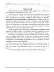
All rights reserved. No part of this publication may be reproduced, stored in a retrieval
system, or transmitted in any form or by any means, mechanical, photocopying,
recording, or otherwise, without the prior written permission of Epson America, Inc. No
patent liability is assumed with respect to the use of information contained herein. While
every precaution has been taken in the preparation of this book, Epson America, Inc.
assumes no responsibility for errors or omissions. Neither is any liability assumed for
damages resulting from the use of information contained herein.
Epson America, Inc. shall not be liable against any damages arising from the use of any
options other than those designated as Original Epson Products by Seiko Epson
Corporation.
Epson and Epson ESC/P are registered trademarks of Seiko Epson Corporation.
General Notice: Other product names used herein are for identification purposes only and
may be trademarks of their respective companies.
Copyright © 1991 by Epson America, Inc.
Torrance, California
ii
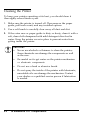
IMPORTANT SAFETY INSTRUCTIONS
1. Read all of these instructions and save them for later reference.
2. Follow all warnings and instructions marked on the product.
3. Unplug this product from the wall outlet before cleaning. Do
not use liquid cleaners or aerosol cleaners. Use a damp cloth for
cleaning.
4. Do not use this product near water.
5. Do not place this product on an unstable cart, stand, or table.
The product may fall, causing serious damage to the product.
6. Slots and openings in the cabinet and the back or bottom are
provided for ventilation; to ensure reliable operation of the
product and to protect it from overheating, these openings must
not be blocked or covered. The openings should never be
blocked by placing the product on a bed, sofa, rug, or other
similar surface. This product should never be placed near or
over a radiator or heat register. This product should not be
placed in a built-in installation unless proper ventilation is
provided.
7. This product should be operated from the type of power source
indicated on the marking label. If you are not sure of the type
of power available, consult your dealer or local power
company.
8. This product is equipped with a 3-wire grounding-type plug, a
plug having a third (grounding) pin. This plug will only fit into
a grounding-type power outlet. This is a safety feature. If you
are unable to insert the plug into the outlet, contact your
electrician to replace your obsolete outlet. Do not defeat the
purpose of the grounding-type plug.
9. Do not locate this product where the cord will be walked on.
iii
10. If an extension cord is used with this product, make sure that
the total of the ampere ratings on the products plugged into the
extension cord do not exceed the extension cord ampere rating.
Also, make sure that the total of all products plugged into the
wall outlet does not exceed 15 amperes.
11. Never push objects of any kind into this product through
cabinet slots, as they may touch dangerous voltage points or
short out parts that could result in a risk of fire or electric
shock. Never spill liquid of any kind on the product.
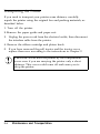
12. Except as specifically explained in the User’s Manual, do not
attempt to service this product yourself. Opening or removing
those covers that are marked “Do Not Remove” may expose you
to dangerous voltage points or other risks. Refer all servicing in
those compartments to service personnel.
13. Unplug this product from the wall outlet and refer servicing to
qualified service personnel under the following conditions:
iv
A.
When the power cord or plug is damaged or frayed.
B.
If liquid has been spilled into the product.
C.
If the product has been exposed to rain or water.
D.
If the product does not operate normally when the
operating instructions are followed. Adjust only those
controls that are covered by the operating instructions,
since improper adjustment of other controls may result in
damage and will often require extensive work by a qualified
technician to restore the product to normal operation.
E.
If the product has been dropped or the cabinet has been
damaged.
F.
If the product exhibits a distinct change in performance,
indicating a need for service.
Contents
Introduction
1
Features .....................................................................
Options .....................................................................
Finding Your Way Around ............................................
Warnings, Cautions, and Notes ......................................
Name of the Parts .......................................................
Where to Get Help ......................................................
1
1
2
2
3
4
Chapter 1 Setting Up the Printer
1-1
Unpacking the Printer ................................................
Choosing a Place for the Printer ..................................
Assembling the Printer ...............................................
Testing the Printer ....................................................
Connecting the Printer to Your Computer .....................
Setting Up Your Application Software ..........................
1-2
1-4
1-6
1-10
Chapter 2 Paper Handling
2-1
1-19
1-21
Using Single Sheets ................................................... 2-2
Using Continuous Paper ............................................. 2-6
Printing on Special Paper ........................................... 2-14
Chapter 3 Using the Printer
3-1
Operating the Control Panel .......................................
Setting the DIP Switches ............................................
Selecting Typestyles ...................................................
Selecting an International Character Set ........................
Choosing a Character Table ........................................
Data Dump Mode .....................................................
3-2
3-5
3-12
3-16
3-17
3-19
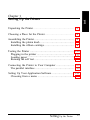
Contents v
Chapter 4 Using the Printer Options
4-1
Cut-Sheet Feeder.. . . . . . . . . . . . . . . . . . . . . . . . . . . . . . . . . . . . . . . . . . . . . . . . . . . . . . 4-2
Film Ribbon . . . . . . . . . . . . . . . . . . . . . . . . . . . . . . . . . . . . . . . . . . . . . . . . . . . . . . ...... 4-8
5-1
Cleaning the Printer .................................................. 5-2
Replacing the Ribbon ................................................. 5-3
Transporting the Printer ............................................. 5-4
Chapter 5 Maintenance and Transportation
6-1
Chapter 6 Troubleshooting
Problems and Solutions .............................................. 6-2
Power Supply .......................................................... 6-3
Printing ................................................................... 6-4
Paper Handling ........................................................ 6-8
Options ................................................................... 6-10
7-1
Printer Specifications ................................................. 7-2
Interface Specifications ............................................... 7-8
Initialization ............................................................. 7-12
Chapter 7 Technical Specifications
8-1
Using the Command Summary . . . . . . . . . . . . . . . . . . . . . . . . . . . . . . . . . . . . 8-2
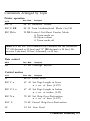
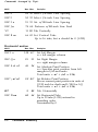
Commands Arranged by Topic . . . . . . . . . . . . . . . . . . . . . . . . . . . . . . . . . . . . 8-3
Chapter 8 Command Summary
Appendix
Character Tables . . . . . . . . . . . . . . . . . . . . . . . . . . . . . . . . . . . . . . . . . . . . . . . . . . . . . .
A-1
A-2
Glossary
GL-1
Index
IN-1
vi
Contents
Introduction
Your new Epson 24-pin dot matrix printer combines a compact
design and high performance with a wide range of features.
Features
In addition to the high-quality printing and ease of operation you
have come to expect from Epson printers, your printer offers the
following:
l
l
l
l
l
l
Easy paper handling, featuring automatic single sheet loading
Fast draft mode printing of up to 192 characters per second at
12 cpi
Seven built-in Letter Quality fonts for producing high-quality
documents
A convenient control panel design that allows direct selection of
fonts
Two paper slots (rear and bottom) for using a variety of paper
types
Compatibility with the Epson ESC/P® commands used by other
Epson LQ printers.
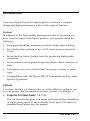
Options
You may choose a cut-sheet feeder or a film ribbon to enhance use
of your printer. For information on these options, see Chapter 4.
l
Single-bin Cut-Sheet Feeder ( # 7341)
The cut-sheet feeder gives you easier and more efficient handling
of single-sheet paper. It automatically feeds up to 100 sheets of
standard bond paper into the printer.
Introduction 1
Introduction
l
Film Ribbon Cartridge ( # 7768)
An optional film ribbon cartridge provides you with even higher
quality printing than the standard fabric ribbon.
Finding Your Way Around
This manual provides fully illustrated, step-by-step instructions for
setting up and operating your printer.
l
l
l
l
Chapter 1 contains information on unpacking, setting up,
testing, and connecting the printer. Be sure to read this chapter
first.
Chapters 2 and 3 include important information on paper
handling and day-to-day operation of your printer.
Chapter 6 contains troubleshooting information. If the printer
does not operate properly or the printed results are not what
you expect, see Chapter 6 for a list of problems and solutions.
Other chapters contain information on general maintenance,
specifications, and printer commands. There is also a glossary of
printer terms and an index.
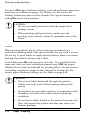
Warnings, Cautions, and Notes
WARNINGS must be followed to avoid bodily injury.
CAUTIONS must be observed to avoid damage to
your equipment.
Notes contain important information and useful tips on the
operation of your printer.
2
Introduction
Introduction
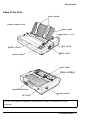
Name of the Parts
edge guides
paper release lever
paper guide
compartment cover
slot cover
printer cover
control panel
platen knob
print head
ribbon cartridge
parallel interface
power switch
AC inlet
Note: In some locations, the power cord is attached to the
printer.
Introduction 3
Introduction
Where to Get Help
A network of authorized Epson Customer Care Centers throughout
the United States offers customer support and service for Epson
products. Epson America provides product information and support
to its dealers and Customer Care Centers.
Call the Epson Consumer Information Center at 1-213-782-2606 for
the following referrals:
l
Your nearest Epson dealer
l
The nearest Customer Care Center for parts and service
l
4
Technical assistance.
Introduction
Chapter 1
Setting Up the Printer
Unpacking the Printer . . . . . . . . . . . . . . . . . . . . . . . . . . . . . . . . . . . . . . . . . . . . . . . . . 1-2
Choosing a Place for the Printer . . . . . . . . . . . . . . . . . . . . . . . . . . . . . . . . . . . 1-4
Assembling the Printer ................................................ 1-6
Installing the platen knob ......................................... 1-6
Installing the ribbon cartridge .................................... 1-6
Testing the Printer .....................................................
Plugging in the printer .............................................
Loading paper .........................................................
Running the self test ................................................
1-10
1-10
1-11
1-17
Connecting the Printer to Your Computer ...................... 1-19
The parallel interface ............................................... 1-19
Setting Up Your Application Software ........................... 1-21
Choosing from a menu ............................................ 1-21
Setting Up the Printer
1-1
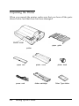
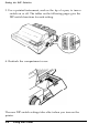
Unpacking the Printer
When you unpack the printer, make sure that you have all the parts
shown below and that none has been damaged.
tractor cover
paper guide
printer
1-2
paper rest
printer cover
platen knob
power cord
ribbon cartridge
Selec Type sticker
Setting Up the Printer
Unpacking the Printer
Note:
You’ll find the platen knob in a piece of the foam packing.
l
l
l
You’ll find the SelecType sticker inside the user’s manual. This
sticker is a useful reference for selecting fonts with the control
panel. You can put this sticker on either the printer cover or
the front cover provided with the optional cut-sheet feeder.
In some locations, the power cord is attached to the printer.
After removing the parts, store the packing materials in case you
ever need to transport your printer.
CAUTION: There are several different versions of the
printer designed for different electrical standards. It is not
possible to adjust the printer for use at another voltage.
The power supply type is shown on the label on the back
of the printer. If it does not show the correct voltage for
your country, contact your dealer.
Setting Up the Printer
1-3
Choosing a Place for the Printer
When selecting a place to set up your printer, be sure to keep the
following in mind:
l
l
l
Place the printer on a flat, stable surface.
Place the printer close enough to the computer for the printer
cable to reach.
Leave adequate room around the printer to allow for easy
operation and maintenance.
CAUTION: Avoid locations that are subject to direct
sunlight, excessive heat, moisture, or dust.
Use a grounded outlet; do not use an adapter plug.
Avoid electrical outlets controlled by wall switches or automatic
timers. Accidental disruption of power can wipe out information
in the memory of your computer or your printer.
Avoid outlets on the same circuit with large motors or other
appliances that might cause fluctuations in line voltage.
Keep the entire computer system away from potential sources of
electromagnetic interference such as loudspeakers or the base
units of cordless telephones.
1-4
Setting Up the Printer
Choosing a Place for the Printer
Note: If you plan to use a printer stand, follow these guidelines:
l
l
l
l
l
Use a stand that supports at least 30 lbs (14 kg), which is
twice the weight of the printer.
Never use a stand that tilts the printer at an angle of more
than 15 degrees from horizontal. If you install a cut-sheet
feeder, keep your printer absolutely level.
If you position the paper supply below the printer stand,
make sure that you allow enough clearance (one inch or 25
mm) to keep the paper from catching on the underside of the
stand. Also see that the distance between the stands supports
is at least 11 inches (280 mm), to accommodate any paper
size you may use.
Position your printer’s power cord and interface cable so that
they do not interfere with paper feeding. If possible, secure
the cables to the printer stand.
Position the paper stack even with the pull-tractor sprocket
units, so that the paper has a straight path into the printer.
Setting Up the Printer
1-5
Assembling the Printer
After choosing a good place for your printer, you install the platen
knob.
Installing the platen knob
You use the platen knob to manually feed paper in the printer when
the printer is turned off. You find the platen knob packed in an
indentation in the white foam packing material.
1. Insert the knob into the hole on the printer’s side and rotate it
until it slips onto the shaft.
2. Push firmly on the knob until it fits against the printer case.
Installing the ribbon cartridge
Before installing the ribbon cartridge, make sure that the printer is
not plugged into an electrical outlet.
1-6
Setting Up the Printer
Assembling the Printer
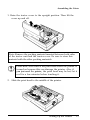
1. Raise the tractor cover to the upright position. Then lift the
cover up and off.
Note: Remove the packing material inserted between both sides
of the tractor unit and the tractor cover. Be sure to store this
material with the other packing materials.
CAUTION: Never move the print head while the printer is
turned on because this can damage the printer. Also, if
you just used the printer, the print head may be hot; let it
cool for a few minutes before touching it.
2. Slide the print head to the middle of the printer.
Setting Up the Printer
1-7
Assembling the Printer
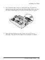
3.
Turn the ribbon-tightening knob in the direction of the arrow.
This removes any slack in the ribbon to make it easier to install.
4.
Hold the ribbon cartridge by its handle and push it firmly down
into position, making sure the plastic hooks fit into the slots.
Press lightly on both ends of the cartridge to be sure the hooks are
properly seated.
1-8
Setting Up the Printer
Assembling the Printer
5. Use a pointed object, such as a ball point pen, to guide the
ribbon between the print head and ribbon guide while you turn
the ribbon-tightening knob to help feed the ribbon into place.
6. Slide the print head from side to side to be sure it moves
smoothly. Also see that the ribbon is not twisted or creased.
Setting Up the Printer
1-9
Testing the Printer
Before connecting your printer to a computer, you use the built-in
self-test function to see that the printer is working properly.
Before running the self test, you need to connect your printer to an
electrical outlet and load paper.
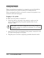
Plugging in the printer
1. Make sure the printer is turned off.
2. Check the label on the back of the printer to make sure the
power rating required by the printer matches that of your
electrical outlet.
CAUTION: If the rated voltage and your outlet voltage do
not match, contact your dealer for assistance. Do not plug
in the power cord.
3. If the power cord is not attached to the printer, connect it to the
AC inlet on the printer’s rear panel.
4. Plug the power cord into a properly grounded electrical outlet.
1-10
Setting Up the Printer
Testing the Printer
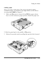
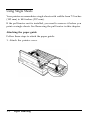
Loading paper
Next, you need to load paper. This section describes loading
continuous paper. If you wish to use single sheets, see the section
on using single sheets in Chapter 2.
1. Make sure the printer is turned off and that the paper release
lever is in the continuous paper position. Attach the paper rest.
2. Slide the print head to the middle of the printer.
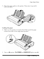
3. Release the sprocket units by pulling the sprocket locks forward.
Setting Up the Printer
1-11
Testing the Printer
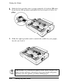
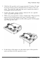
Slide the left sprocket unit to approximately 0.5 inches (12 mm)
from the far left position and push the lever back to lock it in
5. Slide the right sprocket unit to match the width of your paper,
but do not lock it.
CAUTION: Use continuous paper wider than 8 inches (200
mm) for the self test; otherwise, the print head will print
directly onto the platen, possibly damaging it.
1-12
Setting Up the Printer
Testing the Printer
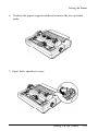
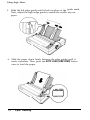
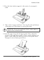
6. Position the paper support midway between the two sprocket
units.
7. Open both sprocket covers.
Setting Up the Printer
1-13
Testing the Printer
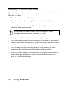
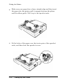
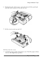
8.
Make sure your paper has a clean, straight edge and then insert
the paper into the printer until it emerges between the platen
and the ribbon guide. Pull it up to the sprocket units.
9.
Fit the holes of the paper over the tractor pins of the sprocket
units, and then close the sprocket covers.
1-14
Setting Up the Printer
Testing the Printer
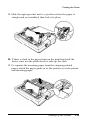
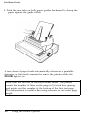
10. Slide the right sprocket unit to a position where the paper is
straight and not wrinkled; then lock it in place.
11. If there is slack in the paper between the print head and the
tractor unit, use the platen knob to take up the slack.
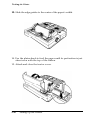
12. To separate the incoming paper from the outgoing printed
paper, attach the paper guide in its flat position over the printer
and incoming paper.
Setting Up the Printer
1-15
Testing the Printer
13. Slide the edge guides to the center of the paper’s width.
14. Use the platen knob to feed the paper until its perforation is just
about even with the top of the ribbon.
15. Attach and close the tractor cover.
1-16
Setting Up the Printer
Testing the Printer
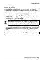
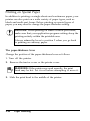
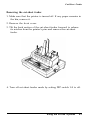
Running the self test
The self test runs in draft mode or Letter Quality (LQ) mode,
depending upon which button you hold down as you turn on the
printer.
1. Make sure the printer is turned off and paper is loaded.
2. While holding down the LINE FEED button (draft mode) or the
FORM FEED button (LQ mode), turn on the printer. After
printing starts, release the button.
CAUTION: After turning the printer off, always wait at
least five seconds before turning it back on. Turning the
power on and off rapidly can damage the printer.
3. The self test continues until the paper runs out or you press the
ON LINE button. When you wish to. stop the test, press the ON
LINE button.
Note: To resume the test, press the ON LINE button again.
Setting Up the Printer
1-17
Testing the Printer
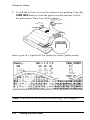
4. To end the self test, be sure the printer is not printing. Press the
FORM FEED button to feed the paper forward and tear it off at
the perforation. Then turn off the printer.
Here is part of a typical self test printed in Letter Quality mode.
Note: If the self test did not print satisfactorily, see Chapter 6.
1-18
Setting Up the Printer
Connecting the Printer to Your Computer
If the self test printed correctly, you are ready to connect your
printer to the computer. Most computers have a parallel interface.
Check your computer’s operating manual, if you are in doubt about
your computer’s interface. If it is parallel, use a suitable shielded
cable to connect your computer to your printer’s built-in parallel
interface, as described in the next section.
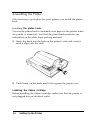
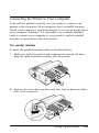
The parallel interface
Connect the parallel interface cable as described below:
1. Make sure both the printer and computer are turned off; then
plug the cable connector securely into the printer.
2. Squeeze the wire clips together until they lock in place on either
side of the connector.
Setting Up the Printer
1-19
Connecting the Printer to Your Computer
Note: If your cable has a ground wire, connect it to the ground
connector beneath the interface connector.
3. Plug the other end of the cable into the computer. (If there is a
ground wire at the computer end of the cable, attach it to the
ground connector at the back of the computer.)
1-20
Setting Up the Printer
Setting Up Your Application Software
Most application programs let you specify the type of printer you
use so that the program can take full advantage of the printer’s
features. Many of these programs provide an installation or setup
section that presents a list of printers.
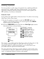
Choosing from a menu
Because the family of Epson printers shares a great many
commands, you can use an application program even if it does not
list your printer on its printer selection menu. Choose from the
following list (the printers are listed in the order of preference):
LQ-200
LQ-500
LQ-510
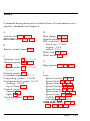
LQ-860(LQ-1060)
LQ-850(LQ-1050)
LQ-2550
LQ-2500
LQ-800(LQ-1000)
LQ-1500
If none of these printers is listed, select the first one available from
the following list: LQ, EX, FX, LX, RX, MX, Epson printer,
Standard printer, Draft printer.
To use all the features of your printer, however, it is best to choose
a program with one of the LQ printers on its menu. If your
program does not list one of these printers, contact the
manufacturer to see if an update is available.
Setting Up the Printer
1-21
Chapter 2
Paper Handling
Using Single Sheets ....................................................
Attaching the paper guide .........................................
Loading the paper ...................................................
Reloading during printing .........................................
2-2
2-2
2-3
2-5
Using Continuous Paper ............................................. .2-6
Installing the pull tractor .......................................... 2-6
Positioning your continuous-paper supply., ................. .2-8
Loading continuous paper ......................................... 2-8
Removing the pull tractor ......................................... 2-12
Printing on Special Paper ........................................... 2-14
The paper-thickness lever ......................................... 2-14
Mu1ti-part forms ..................................................... 2-15
Labels ................................................................... 2-16
Paper Handling 2-1
Using Single Sheets
Your printer accommodates single sheets with widths from 7.2 inches
(182 mm) to 10.1 inches (257 mm).
If the pull-tractor unit is installed, you need to remove it before you
print on single sheets. See Removing the pull tractor in this chapter.
Attaching the paper guide
Follow these steps to attach the paper guide:
1. Attach the printer cover.
2-2
Paper Handling
Using Single Sheets
2. Place the paper guide on the printer. Then raise it up until it
locks into place.
Loading the paper
1. Make sure the printer is turned off and then push the paper
release lever back to the single sheet position.
2. Turn on the printer. The POWER and PAPER OUT lights come on.
Paper Handling 2-3
Using Single Sheets
3.
4.
2-4
Slide the left edge guide until it locks in place at the guide mark.
Next, adjust the right edge guide to match the width of your
paper.
Slide the paper down firmly between the edge guides until it
meets resistance. Then press the AUTO LOAD (LINE FEED) button
once to load the paper.
Paper Handling
Using Single Sheets
Note: If the platen turns without loading the paper, completely
remove the paper and reinsert it more firmly. Then press the
AUTO LOAD button again.
CAUTION: Never advance the paper using the platen knob
while the printer is turned on.
5. Press the ON LINE button to set the printer on line.
To eject the paper, set the printer off line (by pressing the ON LINE
button) and then press the FORM FEED button.
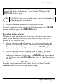
Reloading during printing
When you print a document of more than one page using single
sheet paper, there are two ways your software may leave your
printer at the end of a page:
l
l
If your software sends characters in a continuous stream, the
printer stops printing when it reaches the bottom of the paper.
When this happens, the page ejects and the ON LINE light goes
off automatically.
If your software handles printing page by page, it probably
stops sending characters at the end of a page and prompts you
to insert more paper. In this case, the ON LINE light may remain
on. If it does, press the ON LINE button once to take the printer
off line.
In either case, once the ON LINE light is off, remove the sheet that
has just been printed and load a new sheet as before. Press the
ON LINE button to start printing the next page.
Paper Handling 2-5
Using Continuous Paper
This printer’s paper-handling system allows you to load continuous
paper through either the rear or bottom paper slot depending upon
your paper supply location.
To print on continuous paper, you need to install the pull-tractor
unit. If the pull tractor is already installed, skip to Positioning your
continuous paper supply later in this section.
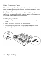
Installing the pull tractor
1. Turn off the printer and remove the printer cover and paper
guide.
2. Attach the paper rest to the rear of the printer.
3. Pull the paper-release lever forward to the continuous-paper
position. Open the slot cover for the tractor unit.
2-6
Paper Handling
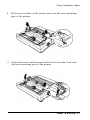
Using Continuous Paper
4. Fit the rear notches of the tractor unit over the rear mounting
pins of the printer.
5. Press the tractor unit forward until its front notches lock onto
the front mounting pins of the printer.
Paper Handling 2-7
Using Continuous Paper
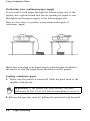
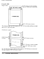
Positioning your continuous-paper supply
If you want to load paper through the bottom paper slot of the
printer, use a printer stand that has an opening for paper to run
through from the paper supply to the bottom paper slot.
Here are two ways to position your printer and supply of
continuous paper:
Make sure you align your paper supply with the paper loaded in
the tractor so that the paper feeds smoothly into the printer.
Loading continuous paper
1. Make sure the printer is turned off. Slide the print head to the
middle of the printer.
WARNING: If the printer was used recently, the print
head may be hot. Let it cool before attempting to move it.
2. Release the sprocket units by pulling the sprocket locks forward.
2-8
Paper Handling
Using Continuous Paper
3. Slide the left sprocket unit to approximately 0.5 inches (12 mm)
from the far left position and push the lever back to lock it in
place. Then slide the right sprocket unit to match the width of
your paper, but do not lock it.
4
Position the paper support midway between the two sprocket
units. Open both sprocket covers.
5
Make sure your paper has a clean, straight edge. Then insert the
paper into the desired paper slot (rear or bottom) until it
emerges between the platen and the ribbon guide. Pull the paper
up to the sprocket units.
6. Fit the holes of the paper over the tractor pins of the sprocket
units, and then close the sprocket covers.
Paper Handling 2-9
Using Continuous Paper
7. Slide the right sprocket unit to a position where the paper is
straight and not wrinkled; then lock it in place. If there is slack
in the paper between the print head and the tractor unit, use the
platen knob to take up the slack.
8. To separate the incoming paper from the outgoing printed
paper, attach the paper guide in its flat position over the printer
and incoming paper. Then slide the edge guides to the center of
the paper’s width.
9.
Use the platen knob to feed the paper until its perforation is just
about even with the top of the ribbon.
10. Attach and close the tractor cover.
11. Turn on the printer.
CAUTION: If you use the platen knob to feed the paper
2-10
Paper Handling
Using Continuous Paper
Setting the top of form position
You may need to set the top of the form to a certain position for
printing on ready-made forms.
To set the top-of-form position at the third line of the paper, for
example, mark the paper 4.1 inches (105 mm) above the
perforation. Then load the paper and align this mark with the mark
on the tractor unit, as shown below. The third line (0.42 inches or
10.6 mm) below the perforation becomes the top-of-form position.
You may have to experiment with setting the top of form position
several times to get this adjustment just right.
Paper Handling
2-11
Using Continuous Paper
Removing the pull tractor
1. If you have a printed document still in the printer, set the
printer off line and press the FORM FEED button to feed the
paper forward. Then tear off the document at the perforation.
2. Remove the paper guide.
3. Tear off the fresh supply at the perforation past the rear paper
slot or below the bottom paper slot.
4.
Press the FORM FEED button to feed the paper past the tractor
pins. If paper remains in the tractor unit, press the FORM FEED
button again.
5. Remove the tractor cover.
2-12
Paper Handling
Using Continuous Paper
6. Hold both ends of the tractor unit and slowly tilt the unit back
until the front notches of the unit are free.
7. Lift the tractor unit up and off.
8. Close the slot cover.
9. Install the paper guide and printer cover. Push the paper release
lever to the single sheet position.
Paper Handling
2-13
Printing on Special Paper
In addition to printing on single sheets and continuous paper, your
printer can also print on a wide variety of paper types, such as
labels and multi-part forms. Before printing on special types of
paper, you may need to change the paper-thickness setting.
CAUTION: When printing on labels or multi-part forms,
make sure that your application program settings keep the
printing entirely within the printable area.
Always return the lever to position 2 when you go back
to printing on ordinary paper.
The paper-thickness lever
Change the position of the paper-thickness lever as follows:
1. Turn off the printer.
2. Remove the tractor cover or the printer cover.
WARNING: If the printer was used recently, the print
head may be hot. Let it cool before attempting to move it.
3. Slide the print head to the middle of the printer.
2-14
Paper Handling
Printing on Special Paper
4. Set the paper-thickness lever to match the thickness of your
paper according to the table below.
Paper Type
Lever Position
2
Ordinary (single sheets or continuous)
Thin paper
2 or 1
Multi-part paper
2 sheets (original + 1 copy)
3 sheets (original + 2 copies)
3
4
4
Labels
Note: If the lever is set to position 4, the printing speed is
reduced.
5. Attach the tractor cover or printer cover.
Multi-part forms
With the pull-tractor unit installed, your printer can print on
continuous multi-part forms. You can use multi-part forms of up to
three parts (including the original). Make sure you set the paperthickness lever to the proper position using the table above.
Paper Handling
2-15
Printing on Special Paper
Except for the paper-thickness setting, you load multi-part paper the
same way as continuous paper. For details, see the section on
loading continuous paper in this chapter. Pay special attention to
setting the top-of-form position.
CAUTION:
l
l
Do not use multi-part forms with the single-sheet
feeding system.
When printing multi-part forms, make sure the
printing stays entirely within the printable area of the
forms.
Labels
When printing labels, always choose the type mounted on a
continuous backing sheet with sprocket holes for use with a tractor.
Do not try to print labels as single-sheets because labels on a shiny
backing sheet almost always slip a little.
Load labels from the bottom paper slot only. You load labels the
same way that you load continuous paper except that the paperthickness lever must be adjusted for printing labels. See the section
on loading continuous paper in this chapter for details. For the
correct paper-thickness setting, see the table on page 2-15.
CAUTION:
l
l
l
2-16
Never feed labels backward through the printer.
Labels can easily peel off the backing and jam the
printer.
Since labels are especially sensitive to temperature and
humidity, use them only under normal operating
conditions.
Do not leave labels loaded in the printer between jobs;
they curl around the platen and may jam when you
resume printing.
Paper Handling
Chapter 3
Using the Printer
Operating the Control Panel . . . . . . . . . . . . . . . . . . . . . . . . . . . . . . . . . . . . . . . .3-2
Lights . . . . . . . . . . . . . . . . . . . . . . . . . . . . . . . . . . . . . . . . . . . . . . . . . . . . . . . . . . . . . . . . . ..3- 2
Buttons ................................................................. 3-3
SelecType .............................................................. 3-4
Other control-panel features ...................................... 3-4
Setting the DIP switches .............................................. 3-5
Changing a DIP-switch setting ................................... 3-5
DIP-switch tables.. .................................................. 3-7
DIP-switch functions ............................................... 3-10
Selecting Typestyles .................................................... 3-12
Character fonts ....................................................... 3-12
Character spacing ................................................... 3-15
Selecting an International Character Set . . . . . . . . . . . . . . . . . . . . . . . . .3-16
Choosing a Character Table . . . . . . . . . . . . . . . . . . . . . . . . . . . . . . . . . . . . . . . . . 3-17
Data Dump Mode . . . . . . . . . . . . . . . . . . . . . . . . . . . . . . . . . . . . . . . . . . . . . . . . . . . . . . 3-19
Using the Printer 3-1
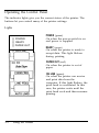
Operating the Control Panel
The indicator lights give you the current status of the printer. The
buttons let you control many of the printer settings.
Lights
POWER (green)
[ ] POWER
[ ] READY
[ ] PAPER OUT
[ ] ON LINE
On when the power switch is on
and power is supplied.
READY (green)
On when the printer is ready to
accept data. This light flickers
during printing.
PAPER OUT (red)
On when the printer is out of
paper.
ON LINE (green)
On when the printer can receive
and print data from the
computer. If this light flickers, the
print head is overheated. In this
case, the printer waits until the
print head cools and then resumes
printing.
3-2
Using the Printer
Operating the Control Panel
Buttons
ON LINE
POWER
READY
PAPER OUT
This button controls the printer’s
on line/off line status. When the
printer is on line, the ON LINE
light is on and the printer can
receive and print data from the
computer.
FORM FEED
When the printer is off line, press
this button to eject a single sheet
of paper or advance continuous
paper to the top of the next page.
When the printer is on line, press
this button to select the character
font. See the section in this
chapter on selecting a font with
SelecType.
LINE FEED/AUTO LOAD
When the printer is off line and
paper is loaded, press this button
to feed the paper one line, or hold
it down to feed paper continuously.
To load single-sheet paper, the
printer must be off line and the
PAPER OUT light on. Then insert a
sheet of paper and press the AUTO
LOAD button.
Using the Printer
3-3
Operating the Control Panel
SelecType
When the printer is on line, the FORM FEED button is used to select
the character font. The two orange indicator lights show which font
is currently selected. (See the description on the tractor cover label
or the SelecType sticker.) You can put the SelecType sticker on the
printer cover or the front cover provided with the optional cut-sheet
feeder. You’ll find the sticker inside the user’s manual.
SelecType
DRAFT
ROMAN
SANS SERIF
COURIER
ON
OFF
PRESTIGE
SCRIPT
OCR-B
ORATOR
BLINKING
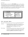
Other control-panel features
The control panel also gives you access to several special functions.
Self test:
The self test lets you check that your printer is
operating properly and gives you a printout of the
current DIP-switch settings. See the section on
testing the printer in Chapter 1 for more
information.
Data dump:
The data dump mode allows advanced users to find
the cause of communication problems between the
printer and application programs. The data dump
mode is explained at the end of this chapter.
3-4
Using the Printer
Setting the DIP Switches
By changing the settings of the two sets of DIP switches inside the
compartment on the right top and side of the printer, you can
control various printer features, such as the character set and page
length. These new settings become effective whenever the printer is
turned on, reset, or initialized.
Changing a DIP-switch setting
1. Make sure the printer is turned off.
2. Remove the compartment cover.
Using the Printer 3-5
Setting the DIP Switches
3. Use a pointed instrument, such as the tip of a pen, to turn a
switch on or off. The tables on the following pages give the
DIP-switch functions for each setting.
4. Reattach the compartment cover.
The new DIP-switch settings take effect when you turn on the
printer.
3-6
Using the Printer
Setting the DIP Switches
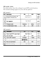
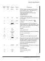
DIP-switch tables
The tables below show the settings for each DIP switch function.
The currrent settings appear on your self test printout.
DIP Switch 1
International character set/
Graphics character set
SeeTable1,2
Sea Table 3
DIP Switch 2
Using the Printer 3-7
Setting the DIP Switches
Table 1
international character sets (DIP switch 1-7 OFF)
When DIP switch 1-7 is off, PC 437 (United States) is the default graphics
character set.
Table 2
Graphics character sets (DIP switch 1-7 ON)
Settings not shown above select PC 437 (United States).
When DIP switch 1-7 is on, USA is the default international character set.
Table 3 Font selection
Font
SW1-4
SW1-5
SW1-6
OFF
OFF
OFF
Epson Roman
ON
OFF
OFF
Epson Sans Serif
OFF
ON
OFF
Epson Courier
Epson Prestige
ON
ON
OFF
Epson Script
OFF
OFF
ON
OCR-B
ON
OFF
ON
Epson Orator
OFF
ON
ON
Epson Draft
ON
ON
ON
3-8
Using the Printer
Setting the DIP Switches
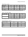
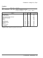
Table 4 Page length
Page length
SW2-1
SW2-2
SW1-8
11 inches
OFF
OFF
OFF
12 inches
ON
OFF
OFF
8.5 inches
OFF
ON
OFF
11.7 inches
ON
ON
OFF
When DIP switch 1-8 is off, A4 size (61 lines) is the default CSF page length.
Table 5 CSF page length
CSF page length
SW2-1
SW2-2
SW1-8
A4 size (61 lines)
OFF
OFF
ON
OFF
ON
ON
ON
OFF
ON
ON
ON
ON
Letter size (65 lines)
When DIP switch 1-8 is on, 11 inches is the default page length.
Table 6 Character spacing
Character spacing
SW2-7
SW2-8
10 cpi
OFF
OFF
12 cpi
ON
OFF
17 cpi
OFF
ON
20 cpi
ON
ON
Using the Printer 3-9
Setting the DIP Switches
DIP switch functions
This section describes the different features you can control with the
printer’s DIP switches.
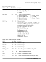
Page length and CSF page length
When DIP switch 1-8 is off (cut-sheet feeder mode is off), DIP
switches 2-1 and 2-2 let you select a page length of 8.5 inches (216
mm), 11 inches (279 mm), 11.7 inches (296 mm), or 12 inches (305
mm).
When DIP switch 1-8 is on (cut-sheet feeder mode is on), you can
select the CSF (Cut-Sheet Feeder) page length of A4- or Letter-size
paper by setting DIP switches 2-1 and 2-2.
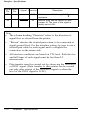
Auto line feed
When auto line feed is on (DIP switch 2-3 on), each carriage return
code (CR) is automatically accompanied by a line feed code (LF). If
your printer is double spacing, turn the DIP switch off. If each line
overprints the next, turn the DIP switch on.
Input buffer capacity
The input buffer stores data from your computer. If you want to
free your computer for other tasks while the printer prints, change
the setting to 8 Kbytes (DIP switch 2-4 on). Before defining userdefined characters, however, be sure to return the setting to 1 Kbyte
(DIP switch 2-4 off).
3-10
Using the Printer
Setting the DIP Switches
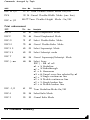
Print direction for graphics
The printer ordinarily prints text bidirectionally for speed and prints
graphics characters unidirectionally for precise vertical alignment.
You can, however, change text printing to unidirectional with the
software command ESC Ul.
If you want to increase printing speed, you can change graphics
character printing to bidirectional by turning DIP switch 2-5 on and
sending the ESC U0 command. If DIP switch 2-5 is off, graphics
character printing is unidirectional whether or not ESC U0 is used.
Skip-over-perforation
DIP switch 2-6 controls the skip-over-perforation function. If this
switch is on when you are using continuous paper, the printer
leaves a one-inch (25.4-mm) space between the last printed line on
one page and the first printable line on the next page so that the
printer skips over the perforation.
Most application programs take care of the top and bottom
margins. Do not turn on skip-over-perforation unless your program
does not provide these margins.
If you adjust your top-of-form position to the proper point, you
can get half of the space at the bottom of one page and half at the
top of the next page, as shown below.
Using the Printer
3-11
Selecting Typestyles
You can produce a wide range of typestyles by combining different
character fonts, widths, and other enhancements. You can select
typestyles using the SelecType feature on your control panel, the
DIP switches, or software commands.
Character fonts
Your printer has eight built-in character fonts. To select a font using
SelecType, follow these steps:
1. Be sure the printer is turned on and the ON LINE light is lit.
Check to see that the printer is not receiving data (the READY
light should not be flickering).
2. Press the FORM FEED button until the two SelecType lights match
the desired font, as shown below.
DRAFT selected
ROMAN selected
SANS SERIF selected
COURIER selected
PRESTIGE selected
SCRIPT selected
OCR-B selected
off
ORATOR selected
on
blinking
The tractor cover label and the SelecType sticker list the state of the
two orange indicator lights for each font. You can put the
SelecType sticker on either the printer cover or the front cover
provided with the optional cut-sheet feeder.
The font selected by SelecType remains effective until another font
is selected by a software command or until the printer is turned off,
reset, or initialized. Epson Courier is the default.
3-12
Using the Printer
Selecting Typestyles
Draft mode uses fewer dots per character for high-speed printing,
which makes it ideal for rough drafts and editing work.
Other SelecType settings are Letter Quality (LQ) fonts. Letter
Quality takes a little longer to print but produces fully-formed
characters for presentation-quality documents.
The following samples show the characters for each font.
Epson Draft
!”#$%&‘()*+,-./0123456789:;<=>?@ABCDEFGHIJK
LMNOPQRSTUVWXZ[\]^_ ‘ a b c d e f g h i j k l m n o p q r s t u v
w x y z { | } ~ Ç ü é â ä à å ç ê ë è ï ì Ä Å É æ Æ ô ö ò û ù ÿ Ö Ü ¢ £ ¥ P tƒ á í ó
Epson Roman
Epson Sans Serif
Epson Courier
Using the Printer
3-13
Selecting Typestyles
Epson Prestige
Epson Script
OCR-B
Note: The OCR-B font is read by an optical character reader
(also known as a document reader or image scanner) for input
into another computer. Print enhancements, such as bold and
underlining, are not read by an optical character reader.
Epson Orator
3-14
Using the Printer
Selecting Typestyles
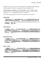
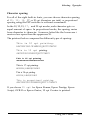
Character spacing
For all of the eight built-in fonts, you can choose character spacing
of 10, 12, 15, 17, or 20 cpi (characters per inch), or proportional
spacing using the DIP switches or software commands.
In the 10, 12, 15, 17, and 20 cpi modes, each character gets an
equal amount of space. In proportional mode, the spacing varies
from character to character. A narrow letter like the lowercase i
receives less space than the uppercase W.
The printout below compares the different types of spacing:
This is 10 cpi printing.
ABCDEFGHIJKLMNOPQRSTUVWXYZ
This is 12 cpi printing.
ABCDEFGHIJKLMNOFQRSTUVWXYZ
This is 15 cpi printing.
ABCDEPCHIJKLFlNOPQRSTUVUXYZ
Thie is 17 cpi printing.
ABCDEFGHIJKLMNOPQRSTUVWXYZ
This is 20 cpi priding.
ABCDEFGHIJKLMNOPQRSTUVWXYZ
This is proportional printing.
ARCDEFGHIJKLMNOPQRSTIJVWXYZ
If you choose 15 cpi for Epson Roman, Epson Prestige, Epson
Script, OCR-B or Epson Orator, 15 cpi Courier is printed.
Using the Printer
3-15
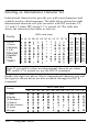
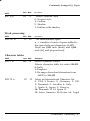
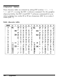
Selecting an International Character Set
International character sets provide you with some characters and
symbols used in other languages. The table below shows the eight
international character sets you can select with DIP switches 1-1,
1-2, and 1-3 when DIP switch 1-7 is turned off. The table also
shows the characters that differ in each set.
Country
DIP SW
ASCII code (hex)
23 24 40 5B 5C 5D 5E 60 78 7C 7D 7E
0 U.S.A.
1-1 1-2
1-3
ON
ON
OFF
ON
OFF
ON
OFF
ON
OFF
ON
ON
ON
ON
OFF
OFF
OFF
OFF
1 France
2 Germany
3 U.K.
4 Denmark
5 Sweden
6 Italy
7 Spain I
ON
OFF
OFF
ON
ON
OFF
OFF
Note: If you wish to select an international character set when
DIP switch 1-7 is turned on, use the ESC R command.
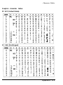
Besides the eight sets above, the six international character sets and
the legal set shown below are also available through the ESC R
command.
ASCII code (hex)
Country
23
24
8 Japan
9 Norway
10 Denmark II
11 Spain II
12 Latin America
13 Korea
64 Legal
3-16
Using the Printer
40
58
5C
50
5E
60
78
7C
70
7E
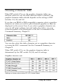
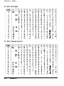
Choosing a Character Table
When DIP switch 1-7 is on, the graphics character tables are
selected; when it is off, the italic character table is selected. The
graphics character table selected depends on the settings of DIP
switches 1-1, 1-2, and 1-3.
If you have an IBM@ or IBM-compatible computer, select a graphics
character set when you wish to print character graphics as they are
displayed on the screen. Even if you select a graphics character set,
you can still print ordinary text and italics. For italics, see your
software manual or the description of the ESC 4 command in the
Command Summary, Chapter 8.
You can also select the italics character set or a graphics character
set using the ESC t command. See the Command Summary in
Chapter 8.
When DIP switch 1-7 is on, the graphics character table is
determined by the DIP switch 1-1, 1-2, and 1-3 settings.
Graphics character sets
Settings not shown above select PC 437 (United States)
Using the Printer
3-17
Choosing a Character Table
The characters in each character set are shown in the Appendix.
Note:
l
To change the setting of a DIP switch, first turn off the
printer. Then change the DIP switch and turn the printer back
on.
l
3-18
Use of the ESC 6 or ESC 7 commands lets you select whether
to print hex codes 90 to 9E and FF as characters (ESC 6) or
control codes (ESC 7).
Using the Printer
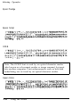
Data Dump Mode
Data dump mode is a special feature that allows experienced users
to find the cause of communication problems between the printer
and application programs. In data dump mode, the printer produces
an exact printout of the codes it receives.
To use data dump mode, follow these steps:
1.
Make sure that paper is loaded and the printer is off.
2. Hold down the FORM FEED and LINE FEED buttons and turn on
the printer.
3. Next, run either an application program or a program you have
written in any programming language. Your printer prints all
the codes it receives in hexadecimal format, as shown below.
Data
Dump
18 4 0
2 0 2 0
1B
5 4
Mode
5 2
6 8
0 0
6 9
1B
7 3
7 4
2 0
01 1B 36 12 18 50 20 20 20
6 9 7 3
2 0 6 1
6 E 2 0 6 5
7 8
6 1
6D 70 6C 65 20 6F 66 20 61 20 64 61 74 61 20 64
7 5 6 0 7 0 2 0 7 0
6 9 7 3 2 0 6 9 7 3
6 8 6 5 7 3 2 0 6 9
7 2 6 9 6 E 7 4 6 F 7 5 7 4 2 E 2 0 5 4 6 8
2 0 6 6 6 5 6 1 7 4 7 5 7 2 6 5 2 0 6 D 6 1
7 4 2 0 6 5 6 1 7 3 7 9 2 0 6 6 6 F 7 2 2 0
. @ . R . . t . . 6 . . P
This is an exa
mplo of a data d
ump p r i n t o u t . T h
is is f e a t u r e m a
kes it easy for
4. To turn off data dump mode, press the ON LINE button to take
the printer off line and then turn off the printer.
By reading the characters printed in the text field on the right
side of the data dump printout (see step 3) or the printout of
hex codes, you can check which codes are being sent to the
printer.
Using the Printer
3-19
Chapter 4
Using the Printer Options
Cut-Sheet Feeder .........................................................
Installing the cut-sheet feeder ......................................
Paper handling .........................................................
Removing the cut-sheet feeder .....................................
4-2
4-2
4-4
4-7
Film Ribbon . . . . . . . . . . . . . . . . . . . . . . . . . . . . . . . . . . . . . . . . . . . . . . . . . . . . . . . . . . . . . . 4-8
Using the Printer Options
4-1
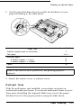
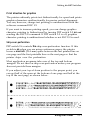
Cut-Sheet Feeder
The optional cut-sheet feeder ( # 7341) makes it possible to handle
single sheets of paper more easily and efficiently. It automatically
feeds up to 100 sheets of standard bond paper into the printer.
Installing the cut-sheet feeder
1.
Make sure the printer is turned off. Remove the paper guide and
printer cover. If the pull tractor is installed, remove it.
2. Turn on the cut-sheet feeder mode by setting DIP switch 1-8 on.
3. Push the paper-release lever back to the single sheet position and
open the slot cover.
4 2
Using the Printer Options
Cut-Sheet Feeder
4. Hold the assembled cut-sheet feeder in both hands and fit its
notches over the pins of the printer.
5. Two front covers are provided with the cut-sheet feeder. Attach
the one for the LQ-500. The cut-sheet feeder manual tells which
one this is.
6. Turn on the printer.
Using the Printer Options
4-3
Cut-Sheet Feeder
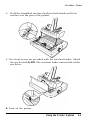
Paper handling
1.
Pull the left and right rear tabs on the cut sheet feeder forward
until the paper guides retract and lock open to allow for paper
loading.
2. Slide the left paper guide all the way to the left. Next, slide the
right paper guide to roughly match the width of your paper.
4-4
Using the Printer Options
Cut-Sheet Feeder
3. Move the front stacker support to the center of your paper’s
width.
4. Take a stack of paper and fan it. Next, tap the side and bottom
of the paper on a flat surface to even up the stack.
CAUTION: Do not use multi-part forms, carbon paper, or
labels in the cut-sheet feeder.
5. Insert the paper along the left paper guide. Then, adjust the
position of the right paper guide so that it closely matches your
paper’s width. Make sure that the position of the guide allows
the paper to move freely up and down.
Using the Printer Options
45
Cut-Sheet Feeder
6. Push the rear tabs on both paper guides backward to clamp the
paper against the guide rollers.
A new sheet of paper loads automatically whenever a printable
character or line-feed command is sent to the printer while the
ON LINE light is on.
Note: Run the self test in cut-sheet feeder mode. The printer
counts the number of lines on the page in l/6-inch line spacing
and prints out this number at the bottom of the first test page.
This information is useful when using software to set a new page
length.
4-6
Using the Printer Options
Cut-Sheet Feeder
Removing the cut-sheet feeder
1. Make sure that the printer is turned off. If any paper remains in
the bin, remove it.
2. Remove the front cover.
3. Tilt the back section of the cut-sheet feeder forward to release
its notches from the printer’s pins and remove the cut-sheet
feeder.
4. Turn off cut-sheet feeder mode by setting DIP switch 1-8 to off.
Using the Printer Options
4-7
Film Ribbon
The optional film ribbon (#7768) provides you with even higher
quality printing than the standard fabric ribbon.
Use the optional film ribbon only when you need especially high
quality printing. For everyday operation, use the standard ribbon.
Install the film ribbon the same way you install the standard
ribbon. See Chapter 1.
4-8
Using the Printer Options
Chapter 5
Maintenance and Transportation
Cleaning the Printer ..................................................... 5-2
Replacing the Ribbon .................................................. .5-3
Transporting the Printer ............................................... 5-4
Maintenance and Transportation
5-1
Cleaning the Printer
To keep your printer operating at its best, you should clean it
thoroughly several times a year.
1. Make sure the printer is turned off. Then remove the paper
guide, pull tractor unit, and any installed options.
2. Use a soft brush to carefully clear away all dust and dirt.
3. If the outer case or paper guide is dirty or dusty, clean it with a
soft, clean cloth dampened with mild detergent dissolved in
water. Keep the printer cover in place to prevent water from
getting inside the printer.
CAUTION:
l
Never use alcohols or thinners to clean the printer;
these chemicals can damage the components as well
as the case.
l
l
l
5-2
Be careful not to get water on the printer mechanism
or electronic components.
Do not use a hard or abrasive brush.
Do not spray the inside of the printer with lubricants;
unsuitable oils can damage the mechanism. Contact
your dealer or a qualified service person if lubrication
is needed.
Maintenance and Transportation
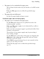
Replacing the Ribbon
When your printing becomes too faint, you need to replace the
ribbon. The Epson # 7753 standard fabric or # 7768 film
replacement ribbon cartridges are recommended. See Installing the
ribbon cartridge in Chapter 1.
Note:
l
Use the optional film ribbon only when you need especially
high quality printing. For everyday operations, use the
standard ribbon.
l
Do not use ribbons designed for nine-pin printers.
Maintenance and Transportation
5-3
Transporting the Printer
If you need to transport your printer some distance, carefully
repack the printer using the original box and packing materials, as
described below.
1. Turn off the printer.
2. Remove the paper guide and paper rest.
3.
Unplug the power cord from the electrical outlet; then disconnect
the interface cable from the printer.
4. Remove the ribbon cartridge and platen knob.
5.
If you have removed the pull tractor and the tractor cover,
replace them now according to the instructions in Chapter 2.
CAUTION: Never hold the printer by the compartment
cover even if you are carrying the printer only a short
distance. This cover could come off and cause you to
drop the printer.
5-4
Maintenance and Transportation
Chapter 6
Troubleshooting
Problems and Solutions . . . . . . . . . . . . . . . . . . . . . . . . . . . . . . . . . . . . . . . . . . . . . . .
6-2
Power Supply . . . . . . . . . . . . . . . . . . . . . . . . . . . . . . . . . . . . . . . . . . . . . . . . . . . . . . . . . . .
6-3
Printing . . . . . . . . . . . . . . . . . . . . . . . . . . . . . . . . . . . . . . . . . . . . . . . . . . . . . . . . . . . . . . . . . . . .
6-4
Paper Handling . . . . . . . . . . . . . . . . . . . . . . . . . . . . . . . . . . . . . . . . . . . .............
6-8
Options . . . . . . . . . . . . . . . . . . . . . . . . . . . . . . . . . . . . . . . . . . . . . . . . . . . . . . . . . . . . . . . . . . . .
6-10
Troubleshooting 6-1
Problems and Solutions
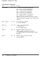
This chapter presents solutions to possible printer problems. If you
have difficulty achieving the desired printing result, first locate the
problem in the listing below and then see the appropriate page for
the solution. If these solutions do not solve your problem, see
Where to Get Help in the introduction.
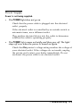
Power supply
l
Power is not being supplied.
See 6-3.
Printing
l
The printer does not print.
See 6-4.
l
The print is faint or uneven.
See 6-5.
Dots are missing in the printed characters or
graphics.
see 6-5.
l
Printed characters are not what you expect.
see 6-5.
l
The print position is not what you expected.
See 6-6.
l
Paper handling
l
Single sheets do not feed properly.
see 6-8.
l
Continuous paper does not feed properly.
see 6-9.
Options
l
6-2
When you use the cut-sheet feeder, the paper
does not feed properly.
Troubleshooting
see 6-10.
Power Supply
Power is not being supplied.
l
The POWER light does not go on.
Check that the power cable is plugged into the electrical
outlet properly.
If the electrical outlet is controlled by an outside switch or
automatic timer, use a different outlet.
Plug another electrical device into the outlet to determine
whether the outlet is operating properly.
l
The POWER light comes on briefly and then goes off. The light
stays off even when the power is turned on again.
Check that the printer’s voltage rating matches the voltage of
your electrical outlet. If the voltages do not match, unplug
the printer and contact your dealer immediately. Do not
reconnect the power cable to an electrical outlet.
Troubleshooting 6-3
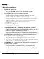
Printing
The printer does not print.
l
The ON LINE light is off.
Press the ON LINE button to put the printer on line.
l
The ON LINE light is on but nothing is printed.
Check that the software is installed properly for your
printer. Check the software’s printer settings.
Check both ends of the interface cable between the printer
and the computer. Make sure your interface cable meets
both the printer and computer specifications.
l
The PAPER OUT light is on.
Load paper in the printer.
l
The printer sounds like it is printing, but nothing is printed.
The ribbon cartridge may not be installed properly. See the
section on ribbon installation in Chapter 1.
The ribbon may be worn out. Replace the ribbon cartridge.
l
The printer makes a strange noise, the buzzer sounds several
times, and the printer stops abruptly.
Turn off the printer and check for paper jams or other
problems. If the printer still does not print correctly, contact
your dealer or a qualified service person.
l
The ON LINE light is flickering but the printer does not print, or
it stops printing abruptly.
The print head is overheated. Wait a few minutes; the
printer resumes printing automatically when the print head
cools.
64
Troubleshooting
Printing
The print is faint or uneven.
l
Printed characters have parts missing at the bottom.
The ribbon cartridge may not be installed properly. See the
section on ribbon installation in Chapter 1.
l
The printout is faint.
The ribbon may be worn out. Replace the ribbon cartridge.
Check that the paper-thickness lever is set correctly for the
paper you are using.
Dots are missing in the printed characters or graphics.
l
A line of dots is missing in the printout.
The print head is damaged. Stop printing and contact your
dealer or a qualified service person to have the printer
serviced.
l
Dots are missing in random positions.
There is either slack in the ribbon or the ribbon has come
loose. Reinstall the ribbon cartridge.
Printed characters are not what you expect.
l
The typestyle or characters that are set by your software cannot
be printed.
Check that the software is correctly installed for your
printer.
l
The font is selected in your software, but the characters are
printed in a different font.
Check that the correct font is selected in SelecType.
Troubleshooting 6-5
Printing
l
The font selected by SelecType does not print.
Your software may be overriding your SelecType setting.
Check the printing style set in your software.
l
The wrong characters are printed.
The wrong character table or the wrong international
character set may be selected. Check the DIP-switch settings.
See 3-16.
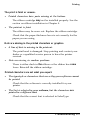
The print position is not what you expected.
l
Printing starts too high or too low on the page.
Adjust the top margin set by your application software.
l
All the text is printed on the same line.
Set DIP switch 2-3 on so that the printer automatically adds
a line-feed code to each carriage return.
l
The text is printed with an extra blank line in between.
Two line-feed signals are being sent. Set DIP switch 2-3 off.
l
Page length does not match the length of the paper.
Change the page-length setting with DIP switches 2-1 and
2-2. see 3-9.
Check the page length set by your application software and
adjust it if necessary.
l
Regular gaps occur in the printout.
One-inch skip-over-perforation may be set. Set DIP switch
2-6 off.
6-6
Troubleshooting
Printing
l
Skip-over-perforation is set, but the perforation does not fall in
the center of the skip.
Adjust the top of form position as described in Chapter 2.
Make sure the DIP-switch settings match your required
paper length. See 3-9.
If your application program is setting the top and bottom
margins, set DIP switch 2-6 off.
If the printer still does not print correctly, try the self test described
in Chapter 1. If the self test works properly, the printer is all right,
and the problem probably lies in the computer, the software, or the
cable. If the self test does not work, contact your dealer or a
qualified service person.
Troubleshooting 6 - 7
Paper Handling
The following section guides you through problems in handling
single sheets and continuous paper. If you are having problems
using the optional cut-sheet feeder, see the section on options
starting on 6-10.
Single sheets do not feed properly.
l
Printing starts too low on the page, or the bottom part of one
page is printed at the top of the next page.
Be sure to choose the correct printer when you choose a
printer from your application program’s menu. See
Chapter 1.
If possible, specify single sheet paper with your application
software.
Use your application software to reduce or eliminate the top
margin and to reduce the page length.
l
When you press the AUTO LOAD button, the platen does not
rotate and paper does not feed.
If the ON LINE light is on, press the ON LINE button once to
set the printer off line.
l
When you press the AUTO LOAD button, the platen rotates but
paper does not feed.
Check that the paper-release lever is pushed back to the
single-sheet position.
6-8
Troubleshooting
Paper Handling
l
The paper feed is crooked or the paper jams.
The cut-sheet feeder mode may be turned on. Set DIP switch
1-8 off.
Make sure the paper size is within the specified range.
see 7-3.
l
The paper does not fully eject.
See that the page-length setting is correct.
Continuous paper does not feed properly.
l
The paper feed is crooked or the paper jams.
See that the paper-release lever is pulled forward to the
continuous-paper position.
Make sure the paper supply is not obstructed by a cable or
some other object.
Make sure that your paper supply is positioned within 3 feet
(1 meter) of the printer.
The position of your paper supply may be preventing it
from feeding straight.
See that the holes on the sides of the paper are aligned with
each other. Also, make sure the sprocket units are locked
and their covers are closed.
Check that the paper-thickness lever is set correctly for the
paper you are using. See 2-15.
Check that the paper size is within the specified range.
see 7-3.
Troubleshooting 6-9
Options
When you use the cut-sheet feeder, the paper does not feed
properly.
l
When a print command is sent from the computer, the platen
rotates but paper does not feed.
Make sure DIP switch 1-8 is set on. See 3-7.
The cut-sheet feeder may be incorrectly installed on the
printer.
See that the paper-release lever is pushed back to the
single-sheet position. See 2-3.
Paper may be jammed near the print head.
You may have loaded too many sheets in the cut-sheet
feeder’s bin.
There may be only one sheet left in the bin. Add more
paper. See 4-4.
l
Two or more sheets feed at the same time.
You may have loaded too many sheets in the cut-sheet
feeder’s bin.
You may have forgotten to fan the stack of paper before
loading it into the bin. Remove the paper and fan it.
l
The paper feed is crooked.
The paper may be old or creased. Use only new, clean
sheets of paper.
There may be too much paper in the stacker.
Make sure that your paper is the proper sire and quality.
l
One page of printing has spread to two pages.
Check that the page-length setting is correct.
6-10
Troubleshooting
Chapter 7
Technical Specifications
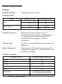
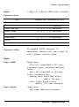
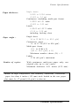
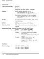
Printer Specifications .................................................
Printing .................................................................
Paper ....................................................................
Mechanical ............................................................
Electrical ...............................................................
Environmental ........................................................
.7-2
7-2
7-3
7-6
7-6
7-7
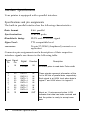
Interface Specifications ................................................ 7-8
Specifications and pin assignments ............................. 7-8
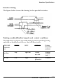
Interface timing .................................................... ..7-11
Printing enabled/disabled signals
and control conditions ........................................... ..7-11
Initialization ............................................................. -7-12
Default Settings ...................................................... 7-12
Technical
Specifications 7-1
Printer Specifications
Printing
Printing method:
24-pin impact dot matrix
Printing speed:
Quality
Character per inch
Characters/second/line
10
160
12
192
Draft
Letter Quality
10
53.3
12
64
Printing direction:
Bidirectional logic-seeking for text.
Unidirectional for graphics. (Bidirectional
for graphics can be selected with DIP
switch 2-5 and the proper software
command.)
Line spacing:
1/6
inch, or programmable in increments of
l/180 inch
Paper feed speed:
100 ms/line at l/6-inch line spacing with
intermittent feeding; 2.2 inches/second with
continuous feeding.
Printable columns:
Character sizes
Maximum printed characters
10 cpi
80
12 cpi
96
15 cpi
120
17 cpi
137
20 cpi
160
Proportional
7-2
Technical Specifications
69 (maximum-width character)
160 (minimum-width character)
Printer Specifications
1 Kbyte or 8 Kbytes (DIP-switch selectable)
Buffer:
Character fonts:
Font
Available sizes (characters per inch)
Epson Draft
10, 12, 15, 17, 20
Epson Roman
10, 12, 15, 17, 20, proportional
Epson Sans Serif
10, 12. 15, 17, 20, proportional
Epson Courier
10, 12, 15, 17, 20, proportional
Epson Prestige
10, 12. 15, 17, 20, proportional
Epson Script
10, 12, 15, 17, 20, proportional
OCR-B
10
Epson Orator
10
Character tables:
96 standard ASCII characters, 14
international character sets, and a legal set,
and 5 graphics character tables
Paper
Paper width:
Single sheet
7.2 to 10.1 inches (182 to 257 mm)
Continuous paper (including multi-part
forms)
4.0 to 10.0 inches (101 to 254 mm)
Labels (continuous only)
backing sheet: 4.0 to 10.0 inches
(101 to 254 mm)
label: 2 l/2 x 1 5 / 1 6 i n c h e s
(63.5 x 23.8 mm) minimum
Paper length:
Single sheet
14.3 inches (364 mm) maximum
Technical Specifications 7-3
Printer Specifications
Printable area:
Single sheet
0.12" (3 mm) or more on paper
that is 9" (229 mm) or less wide.
0.53” (13.5 mm) or more
The minimum right and left margins are 1.06” (27 mm) when printing on paper
that is 10.1" (257 mm) wide.
Continuous paper
0.35" (9 mm)
or more
0.35” (9 mm) or more
0.51" (13 mm) or more on paper
that is 9.5” (242 mm) or less
wide.
For 10” (254 mm) paper width, the left margin is 1.02" (28 mm) or more and
the right margin is 0.94” (24 mm) or more.
7-4
Technical Specifications
Printer Specifications
Paper thickness:
Single sheets
0.0025 to 0.004 inches
(0.065 to 0.1 mm)
Continuous (including multi-part forms)
0.0025 to 0.01 inches
(0.065 to 0.25 mm)
Labels
0.0063 to 0.0075 inches
(0.16 to 0.19 mm)
including backing sheet
Paper weight :
Single sheet
14 to 22 lb (52.3 to 82.0 g/m2)
Continuous paper
14 to 22 lb (52.3 to 82.0 g/m2)
Multi-part forms
[12 to 15 lb] x N
([40 to 58.2 g/m2] x N)
Maximum number sheets (N) = 3
Labels
17 lb (68 g/m 2 ) maximum
Number of copies:
With continuous multi-part paper only: one
original plus up to two copies.
Maximum thickness: 0.01 inches (0.25 mm)
N o t e : In high temperature and humidity conditions, continuous
paper less than 6 inches (152 mm) wide loaded in the rear paper
slot must be 17-pound (64 g/m 2 ) or heavier.
Technical Specifications
7-5
Printer Specifications
Mechanical
Paper-feed methods:
Friction
Pull tractor
Single-bin cut-sheet feeder (optional)
Ribbon:
Black ribbon cartridge #7753:
Life expectancy (in LQ, at 48
dots/character): 2 million characters
Film ribbon cartridge # 7768 (optional):
Life expectancy (in LQ): 0.2 million
characters
MCBF:
For all components (excluding print head):
3 million lines
MTBF:
4000 power on hours (25% duty)
Print head life:
200 million strokes per wire (with fabric
ribbon)
Dimensions and weight: (excluding knob and paper guide)
15.3 inches (390 mm)
Width:
12.6 inches (320 mm)
Depth:
5.2 inches (131 mm) without
Height:
pull tractor
5.9 inches (149.5 mm) with pull
tractor
Approx. 14.1 lb (6.4 kg)
Weight:
without pull tractor
Approx. 15.2 lb (6.9 kg) with
pull tractor
Electrical
Rated voltage:
7-6
AC 120 V (120 V model)
AC 220 V (220 V model)
AC 240 V (240 V model)
Technical Specifications
Printer Specifications
Input voltage range:
AC 103.5 to 132 V (120 V model)
AC 198 to 242 V (220 V model)
AC 216 to 264 V (240 V model)
Rated current:
1.8 A (120 V model)
0.9 A (220 V model, 240 V model)
Power consumption:
(during self
10 cpi)
Approx. 36
Approx. 38
Approx. 38
test printing in draft mode, at
W (120 V model)
W (220 V model)
W (240 V model)
Rated frequency range: 50 to 60 Hz
Input frequency range: 49.5 to 60.5 Hz
Insulation resistance:
Dielectric strength
(between AC line
and chassis):
10 M minimum (at DC 500 V between AC
power line and chassis)
120 V model:
AC 1.0 kV (rms), 1 minute
AC 1.2 kV (rms), 1 second
220 V model, 240 V model:
AC 1.25 kV (rms), 1 minute
AC 1.5 kV (rms), 1 second
Environmental
Temperature:
Operation: 41° to 95°F (5° to 35°C)
Storage:
-22° to 140°F (-30° to 60°C)
Humidity:
Operation: 10% to 80% RH without
condensation
Storage:
5% to 85% RH without
condensation
Technical Specifications 7-7
Interface Specifications
Your printer is equipped with a parallel interface.
Specifications and pin assignments
The built-in parallel interface has the following characteristics:
Data format:
8-bit parallel
Synchronization:
STROBE pulse
Handshake timing:
BUSY and ACKNLG signal
Signal level:
TTL compatible level
connector:
36-pin 57-30360 (Amphenol) connector or
equivalent
Connector pin assignments and a description of their respective
interface signals are shown in the following table.
Signal Signal
Pin
Pin
Signal
Direction
Description
1
19
STROBE
IN
STROBE pulse to read data. Pulse width
2
3
4
5
6
7
8
9
20
21
22
23
24
25
26
27
DATA 1
DATA 2
DATA 3
DATA 4
DATA 5
DATA 6
DATA 7
DATA 8
IN
IN
IN
IN
IN
IN
IN
IN
These signals represent information of the
1st to 8th bits of parallel data, respectively.
Each signal is at HIGH level when data is
logical 1 and LOW when it is logical 0.
10
10
ACKNLG
OUT
About an 11-microsecond pulse. LOW
indicates that data has been received and
that the printer is ready to accept more
data.
7-8
Technical Specifications
Interface Specifications
Signal
Pin
Return
Pin
Signal
Direction
11
29
BUSY
OUT
A HIGH signal indicates that the printer
cannot receive data. The signal goes
HIGH in the following cases:
1) During data entry (ea. char. time)
2) During printing
3) When off line
4) During printer-error state
12
30
PE
OUT
A HIGH signal indicates that the printer is
out of paper.
13
-
SLCT
OUT
Pulled up to +5 V through 3.3 K
resistance.
14
-
AUTO
FEED XT
IN
When this signal is LOW, the paper is
automatically fed 1 line after printing. (The
signal level can be fixed to this by setting
DIP switch 2-3 to ON.)
15
-
NC
-
Unused.
16
-
GND
-
Logic ground level.
17
-
CHASSIS
GND
-
Printer’s chassis ground, which is isolated
from the logic ground.
18
-
NC
-
Unused.
19-30
-
GND
-
Twisted-pair return signal ground level.
31
-
INIT
IN
When this level becomes LOW, the printer
controller is reset to its power-up state and
the print buffer is cleared. This level is
usually HIGH; its pulse width must be
more than 50 microseconds at the
receiving terminal.
32
-
ERROR
OUT
This level becomes LOW when the printer is:
1) in paper out state.
2) off line.
3) in error state.
33
-
GND
-
Same as for Pins 19-30.
34
-
NC
-
Unused.
Description
Technical Specifications 7-9
Interface Specifications
Signal Return
Pin
Pin
35
36
-
Signal Direction
-
OUT
SLCT IN
IN
Description
Pulled up to +5 V through 3.3 K
resistance.
Internal fixing can be carried out with
Jumper J6. The level of this signal is
factory-set to LOW.
Note:
l
The column heading “Direction” refers to the direction of
signal flow as viewed from the printer.
l
l
l
7-10
“Return” denotes the twisted-pair return, to be connected at
signal ground level. For the interface wiring, be sure to use a
twisted-pair cable for each signal and to complete the
connection on the return side.
All interface conditions are based on TTL level. Both the rise
and fall times of each signal must be less than 0.2
microseconds.
Data transfer must be carried out by observing the ACKNLG
or BUSY signal. (Data transfer to this printer can be carried
out only after receipt of the ACKNLG signal or when the
level of the BUSY signal is LOW.)
Technical Specifications
Interface Specifications
Interface timing
The figure below shows the timing for the parallel interface.
Printing enabled/disabled signals and control conditions
The table below shows the relationship between printing being
enabled or disabled and the on-line/off-line status.
ON LINE
(Indicator
on)
ERROR
BUSY
ACKNLG
Printing
(Disabled/
enabled)
on line
High
High/Low
Pulsed
ea. char.
Enabled
(normal
cond.)
off line
Low
High
Not
generated
Disabled
Technical Specifications
7-11
Initialization
There are three ways that the printer can be initialized (returned to
a fixed set of conditions).
Hardware initialization
1. The power is turned on.
2. The printer receives an INIT signal from the
parallel interface (pin 31 goes LOW).
Software initialization
3. Software sends the ESC @ (Initialize the printer)
command.
Default Settings
The table below shows the default conditions that become effective
when the printer is initialized.
Item
Default condition
Top of form position
Current paper position
Page length
The current DIP-switch setting
Left and right margins
Cancelled
Line spacing
1/6 inch
Vertical tab position
Cleared
Horizontal tab positions
Every eight characters
Font selection
Hardware: reset to current DIP switch setting.
Software: reset to the current
SelecType setting.
Special printing effects
Cancelled
User-defined character set
Hardware: cleared
Software: deselected only
In addition, hardware initialization clears the data buffer of all text.
7-12
Technical Specifications
Chapter 8
Command Summary
Using the Command Summary ........................................ 8-2
Commands Arranged by Topic .....................................
Printer operation ......................................................
Data control ...........................................................
Vertical motion ........................................................
Horizontal motion ....................................................
Overall printing style ...............................................
Print size and character width.....................................
Print enhancement ....................................................
Word processing ......................................................
Character tables .......................................................
User-defined characters..............................................
Graphics ................................................................
8-3
8-3
8-3
8-3
8-4
8-5
8-5
8-6
8-7
8-7
8-8
8-9
Command Summary
8-1
Using the Command Summary
The following section lists and describes all the commands by topic.
If a command has no parameters, it is merely listed. If it has
parameters, they are explained. The parameters are indicated by
lowercase italicized letters, usually n. The examples below show
how the parameters are indicated.
ESC @ is a command with no parameters.
ESC U 1/0 is a command that uses 1 to turn the feature on and 0
to turn it off.
ESC $ n1 n2 is a command with two parameters.
ESC D m is a command with a variable number of parameters.
8-2
Command Summary
Commands Arranged by Topic
Printer operation
ASCII
Dec. Hex.
Description
ESC @
64 40 Initialize Printer
ESC U 1/0
85 55 Turn Unidirectional Mode On/Off
ESC EM n
25 19 Control Cut-Sheet Feeder Mode
4: Turns mode on
R: Ejects a sheet
0: Turns mode off
Note: For the ESC EM command the variables are the characters
“0” (48 decimal or 30 hex) and “4” (52 decimal or 34 hex). Do
not use 0 decimal, 00 hex, 4 decimal, or 04 hex.
Data control
ASCII
CR
Dec. Hex.
Description
13 0D Carriage Return
Vertical motion
ASCII
Dec. Ha.
Description
FF
12 0C Form Feed
ESC C n
67 43 Set Page Length in Lines
n = no. of lines (1-127)
ESC C 0 n
67 43 Set Page Length in Inches
n = no. of inches (1-22)
ESC N n
78 4E Set Skip-Over-Perforation
n = no. of lines (1-127)
ESC 0
79 4F Cancel Skip-Over-Perforation
LF
10 0A Line Feed
Command Summary 8-3
Commands Arranged by Topic
ASCII
Dec. Hex.
Description
ESC 0
48 30 Select l/8-inch Line Spacing
ESC 2
50 32 Select l/6-inch Line Spacing
ESC 3 n
51 33 Set n/180-inch Line Spacing
ESC J n
74 4A Perform n/l80-inch Line Feed
VT
11 0B Tab Vertically
ESC B nn
66 42 Set Vertical Tabs
Up to 16 tabs; last n should be 0 (1-255)
Horizontal motion
ASCII
Dec. Hex.
Description
ESC 1 n
108 6 C
Set Left Margin
n = left margin column
ESC Q n
81
51
Set Right Margin
n = right margin column
ESC $ nl n2
36
24
Set Absolute Print Position
n = Specifies print position from left
margin in l/60-inch units
Total units = n1 + (n2 x 256)
ESC \ n1 n2
92 SC
HT
ESC D nn
8-4
Set Relative Print Position
Moves current print position in units of
l/120 inch for draft and l/180 for LQ
Total units = n1 + (n2 x 256)
9
09
Tab Horizontally
68
44
Set Horizontal Tabs
Up to 32 tabs (1-255) entered in
ascending order
Terminated by 0
Command Summary
Commands Arranged by Topic
Overall printing style
ASCII
Dec. Hex.
ESC x n
120
ESC k n
107
ESC ! n
33
78
6B
21
Description
Select Letter Quality or Draft
1: Letter Quality
0: Draft
Select Typestyle Family
0: Epson Roman
4: Epson Script
1: Epson Sans Serif
5: OCR-B
2: Epson Courier
7: Epson Orator
3: Epson Prestige
Master Select
To find the value of n add together the
numbers of the typestyles you want to
combine from the list below:
10 cpi: 0 decimal, 00 hex
12 cpi: 1, 01
proportional: 2, 02
condensed: 4, 04
emphasized: 8, 08
double-strike: 16, 10
double-width: 32, 20
italics: 64, 40
underline: 128, 80
Print size and character width
ASCII
Dec. Hex.
Description
ESC P
80
50
Select 10 cpi
ESC M
77 4D
Select 12 cpi
ESC g
103
67
Select 15 cpi
ESC p l/0
112
70
Turn Proportional Mode On/Off
SI
15
DC2
18
so
14
0F
12
0E
Select Condensed Mode
Cancel Condensed Mode
Select Double-Width Mode (one line)
Command Summary 8-5
Commands Arranged by Topic
ASCII
Dec. Ha.
Description
ESC W l/0
87 57 Turn Double-Width Mode On/Off
DC4
20 14 Cancel Double-Width Mode (one line)
ESC w l/0
119 77 Turn Double-Height Mode On/Off
Print enhancement
ASCII
Dec.
Hex.
Description
ESC E
69
45
Select Emphasized Mode
ESC F
70
46
Cancel Emphasized Mode
ESC G
71
47
Select Double-Strike Mode
ESC H
72
48
Cancel Double-Strike Mode
ESC S 0
83
53
Select Superscript Mode
ESC S 1
83
53
Select Subscript mode
ESC T
84
54
Cancel Superscript/Subscript Mode
ESC ( - nn
40
28
Select Score
ESC ( - 301 n1 n 2
n l = 1: Underline
n1 = 2: Strikethrough
n l = 3: Overscore
n 2 = 0: Cancel score line selected by n1
n2 = 1: Single continuous line
n2 = 2: Double continuous line
n2 = 5: Single broken line
n2 = 6: Double broken line
ESC - 1/0
45
2D Turn Underline Mode On/Off
ESC 4
52
34
Select Italic Mode
ESC 5
53
35
Cancel Italic Mode
8-6 Command Summary
Commands Arranged by Topic
ASCII
Dec. Hex.
ESC q n
113
71
Description
Select Character Style
0: Normal style
1: Outline
2: Shadow
3: Outline with shadow
Word processing
ASCII
Dec. Hex.
32
ESC SP n
20
Description
Set Intercharacter Space
n = number of units of space added to
the space between characters (1-127)
Units are l/120 inch (draft) and l/l80
inch (LQ and proportional)
Character tables
ASCII
Dec. Hex.
Description
ESC t n
116 74
Select Character Tables
Selects character table for codes 128-255
0: Italic
1: Graphics
2: Re-maps download characters from
O-127 to 128-255
ESC R n
82
52
Select an International Character Set
0: USA 1: France 2: Germany 3: UK
4: Denmark 5: Sweden 6: Italy
7: Spain 8: Japan 9: Norway
10: Denmark II 11: Spain II
12: Latin America 13: Korea 64: Legal
Command Summary 8-7
Commands Arranged by Topic
Userdefined characters
ASCII
Dec. Hex.
26
Description
ESC & nn
38
Define User-Defined Characters
ESC & 0 nl n2 d0 d1 d2 data
n1 = code for first character
n2 = code for last character
d0 = left space of character
dl = Body width of character
d2 = right space of character
data: 3 bytes required for each column;
super/subscripts require only 2 bytes per
column
ESC : 0 n 0
58 3A
Copy ROM to RAM
n = font family
ESC % n
37
25
Select User-Defined Set
0: Normal set
1: User-defined set
ESC 6
54
36
Enable Printable Characters
With graphics character sets this
command enables the printing of codes
128-159
ESC 7
8-8
55
37
Enable Upper Control Codes
Cancels ESC 6
Command Summary
Commands Arranged by Topic
Graphics
ASCII
ESC * m n1 n2
Dec. Hex.
42 2A
Description
Select Graphics Mode
Total columns = n1 + (n2 x 256)
Option
Singledensity
Double-density
High-speed double density’
Quadruple-density’
CRT I
CRT II
Single-density
Doubledensity
CRT Ill
Triple-density
Hex-density l
Pins
8
8
8
8
8
8
24
24
24
24
24
m Horiz. dots/inch
0
1
2
3
4
6
32
33
38
39
40
60
120
120
240
80
90
60
120
90
180
360
*Adjacent dots cannot be printed in this mode.
Command Summary 8-9
Appendix
Character Tables ........................................................ A-2
Italic character table ................................................. A-2
Graphics character tables .......................................... A-3
Appendix A - 1
Character Tables
These character tables are selected by setting DIP switches 1-1, 1-2,
1-3 and 1-7, or using the ESC t software command. For the graphics
character tables, the ESC 6 and ESC 7 software commands let you
select whether hex codes 80 to 9F are characters (ESC 6) or control
codes (ESC 7).
Italic character table
A-2
Appendix
Character Tables
Graphics character tables
PC 437 (United States)
PC 850 (Multilingual)
Appendix A-3
Character Tables
PC 860 (Portugal)
PC 863 (Canada-French)
A-4
Appendix
Character Tables
PC 865 (Norway)
Appendix A-5
Glossary
The following definitions apply specifically to printers.
application program
A software program that helps you carry out a particular task, such
as word processing or financial planning.
ASCII
American Standard Code for Information Interchange. A
standardized coding system for assigning numerical codes to letters
and symbols.
auto line feed
When this feature is selected using a DIP switch, each carriagereturn code (CR) is automatically followed by a line-feed (LF) code.
bidirectional printing
Printing in which the print head prints from left to right only on
every other line. On the other lines, it prints from right to left. This
increases the speed of printing because the head prints in both
directions.
bit
A binary dig.3 (0 or l), which is the smallest unit of information
used by a printer or computer.
byte
A unit of information consisting of eight bits.
character set
A collection of letters, numerals, and symbols.
Glossary
GL-1
character table
A portion of the printer’s standard ASCII character set that you use
for graphic symbols or italic characters.
characters per inch (cpi)
A measure of the size of text characters. Ten cpi is the printer’s
default setting.
continuous paper
Paper that has sprocket-feed holes on each side, is perforated
between pages, and is supplied in a folded stack. Also called fanfold
paper.
control code
Special codes used to control printer functions such as performing a
carriage return or line feed.
cpi
See characters per inch.
cut-sheet feeder (CSF)
An optional, detachable device that automatically feeds single sheets
of paper into the printer.
data dump
A troubleshooting feature that helps advanced users find the cause
of communication problems between the printer and the computer.
When the printer is in data dump mode, it prints each code it
receives in hexadecimal notation and ASCII code. Also called hex
dump.
default
A value or setting that takes effect when the equipment is turned
on, reset, or initialized.
GL-2 Glossary
DIP switches
Small switches in a printer that control various printer functions
and set the default status of the printer when it is turned on or
initialized. DIP stands for dual in-line package.
dot matrix
A method of printing in which each letter or symbol is formed by a
pattern (matrix) of individual dots.
double-height printing
Printing in which each character is twice as tall as normal.
double-strike printing
A way of producing bolder characters. Each character is printed
twice.
double-width printing
Printing in which each character is twice as wide as normal.
draft
One of two print qualities available on your printer. Draft uses a
minimum number of dots per character for high-speed printing. See
also Letter Quality.
emphasized printing
A way of producing darker characters. Each character is printed
twice, with the second slightly to the right of the first.
ESC/P
Abbreviation for Epson Standard Code for Printers. This system of
commands gives you software control of your printer from your
computer. It is standard for all Epson printers and supported by
most application software for personal computers.
font
A font is a style of type designated by a family name.
Glossary
GL-3
form feed
A control code and a panel button that advances the paper to the
next top of form position.
initialize
To establish the initial default status of the printer by turning on
the printer or sending an INIT signal.
interface
The connection between the computer and the printer. A parallel
interface transmits data one character or code at a time, and a serial
interface transmits data one bit at a time.
italics
A typestyle in which the characters slant. This sentence is italicized.
Also, a character table that contains italicized characters and
symbols.
Letter Quality (LQ)
One of two print qualities available on your printer. Letter Quality
provides better readability and appearance at a reduced print speed.
See also draft.
line feed
A control code and a panel button that advances the paper one line
space.
on line
When the printer is on line, it is in communication with the
computer connected to it. The ON LINE button controls the printer’s
on line/off line status.
parallel interface
See interface.
GL-4
Glossary
platen
The black roller that provides a backing for the paper during
printing.
proportional printing
Printing in which the width of the character varies from character
to character. For example, a capital W receives much more space
than a lowercase i. The result looks more like a typeset book than a
typewritten draft.
RAM
Random Access Memory. The portion of the printer’s memory used
as a buffer and for storing user-defined characters. All data stored
in RAM is lost when the printer is turned off.
reset
To return a printer to its defaults by sending a command or an
INIT signal or by turning the printer off and then back on.
self test
A method for checking the operation of the printer. When the self
test is run, the printer prints out its current DIP switch settings and
the characters that are stored in its ROM.
subscripts
Printing in which each character is printed at about two-thirds the
normal height in the lower part of the character space.
superscripts
Printing in which each character is printed at about two-thirds the
normal height in the upper part of the character space.
top of form
The position on the paper that the printer recognizes as the first
printable line. The printer feeds the paper to this position when it
loads the paper.
Glossary
GL-5
unidirectional printing
Printing in one direction only. Unidirectional printing is useful for
printing graphics because it allows more precise vertical alignment
than bidirectional printing.
user-defined characters
Characters that are defined and stored in the printer by the user.
Also known as download characters.
GL-6 Glossary
Index
Command descriptions are not indexed here. For information on a
specific command, see Chapter 8.
A
D
Auto line feed, 3-7, 3-10
AUTO LOAD button, 2-4, 3-3
C
Data dump, 3-4, 3-19
Default settings, 7-12
DIP switches, 3-5-11
functions, 3-10-11
setting, 3-5-6
tables, 3-7-9
Draft font, 3-8, 3-13
Draft mode, 1-17
Character fonts, 3-8, 3-12-14
Character spacing, 3-7, 3-9,
E
B
Buttons, control panel, 3-3
3-15
Character tables, 3-7, 3-17-18,
A-2-5
Cleaning printer, 5-2
Command summary, 8-1-9
Connecting printer, 1-19-20
Continuous-feed paper, 2-6-13
loading, 2-8-10
top of form, 2-11
Control panel, 3-2-4
buttons, 3-3
lights, 3-2
Cut-sheet feeder, 3-7, 3-10,
4-2-7
Edge guides, 1-16, 2-4, 2-10
F
Fonts
Epson Courier, 3-8, 3-13
Epson Draft, 3-8, 3-13
Epson Orator, 3-8, 3-14
Epson Prestige, 3-8, 3-14
Epson Roman, 3-8, 3-13
Epson Sans Serif, 3-8, 3-13
Epson Script, 3-8, 3-14
OCR-B, 3-8, 3-14
selecting, 3-4, 3-12-14
FORM FEED button, 1-17, 2-5,
2-10, 2-11, 3-3, 3-19
Index
IN-1
P
G
Graphics character sets, 3-7-8,
3-17-18, A-3-15
Page length, 3-7, 3-9
Paper
loading, 1-11-16, 2-3-5,
2-8-10, 4-4-6
I
Initialization, 7-12
Input buffer, 3-7, 3-10, 7-3
Interface specifications, 7-B-11
International character sets,
3-7-8, 3-16
Italic character table, 3-7-8,
3-17-18, A-2
multi-part forms, 2-15-16,
7-5
specifications, 7-3-5
top of form, 2-11
Paper guide
attaching, 1-15, 2-2, 2-10
continuous-feed paper, 1-15,
2-10
single sheet paper, 2-2
PAPER OUT light, 2-3, 3-2
L
Letter Quality fonts, 3-8
3-12-14
Letter Quality mode, 1-17
LINE FEED button, 1-17, 2-10,
3-3, 3-19
Line spacing, 7-2
Loading paper
continuous, 1-11-16, 2-8-10
single-sheet, 2-3-5
M
Multi-part forms, 2-15-16, 7-5
O
OCR font, 3-8, 3-14
ON LINE light, 3-2, 3-12, 4-6
ON LINE button, 1-17, 2-5, 3-3
IN-2
Index
Paper-release lever, 2-3, 2-6, 4-2
Paper rest, 1-11, 2-6
Paper-thickness lever, 2-14-15
Parallel interface
connecting, 1-19-20
specifications, 7-B-11
Platen knob, 1-6
POWER light, 2-3, 3-2
Printable area, 7-4
Print direction, 3-7, 3-11, 7-2
Printer
assembling, 1-6-9
cleaning, 5-2
cover, 1-2, 2-2
default settings, 7-12
specifications, 7-2-7
testing, 1-10-18
transporting, 5-4
unpacking, 1-2-3
voltage, 7-7
Print head, 7-6
Print speed, 7-2
Problems, see Troubleshooting
Proportional spacing, 3-15, 7-2
Pull tractor
installing, 2-6-7
removing, 2-12-13
R
READY light, 3-2
Ribbon cartridge
installing, 1-7-9
replacing, 5-3
specifications, 7-6
Tractor-unit slot cover, 2-6,
2-13
Transporting printer, 5-4
Troubleshooting, 6-2-10
Typestyles, see also Fonts
U
Unpacking printer, 1-2-3
V
Voltage, 7-7
S
SelecType, 3-4, 3-12-14
SelecType light, 3-4, 3-12
Self test, 1-17-18, 3-4
Single-sheet paper, 2-2-5
loading, 2-3-5
Skip-over-perforation, 3-7, 3-11
Specifications, 7-2-12
T
Technical specifications, 7-2-12
Testing printer, 1-10-18
Top-of-form position, 2-11
Tractor cover, 1-2, 1-7, 1-16,
2-10
Tractor unit
installing, 2-6-7
removing, 2-12-13
Index
IN-3
3000 KEY FEATURES:
n
Sharp Letter Quality Printing
n Fast 192 CPS Draft Print Speed
n
High-Resolution Graphics Capability
n
Seven Popular Built-In LQ Fonts
n
Multiple Paper Feed Paths
n
Versatile Paper Handling
n 8KB Input Buffer
n
Epson Two Year Limited Warranty
EPSON AMERICA, INC.
Printed in Japan 91.02-4.5
20770 Madrona Avenue
Torrance, California 90503