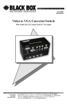
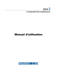
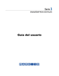
1
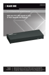
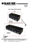
March 2005
AC1031A-2
AC1031A-4
2 and 4 Channel DVI Splitter / Extender
AC1031A-2
2-Channel
AC1031A-4
4-Channel
CUSTOMER
SUPPORT
INFORMATION
Order toll-free in the U.S. 24 hours, 7 A.M. Monday to midnight Friday: 877-877-BBOX
FREE technical support, 24 hours a day, 7 days a week: Call 724-746-5500 or fax 724-746-0746
Mail order: Black Box Corporation, 1000 Park Drive, Lawrence, PA 15055-1018
Web site: www.blackbox.com • E-mail: [email protected]
DVI Splitter
TRADEMARKS USED IN THIS MANUAL
BLACK BOX and its logo
Corporation.
are registered trademarks of Black Box
Apple and Macintosh are registered trademarks of Apple Computer, Inc.
IBM is a registered trademark of International Business Machines
Corporation.
SGI is a registered trademark of Silicon Graphics, Inc.
Sun and Sun Microsystems are registered trademarks of Sun Microsystems,
Inc. in the United States and other countries.
Any other trademarks mentioned in this manual are acknowledged to be
the property of the trademark owners.
1
Model AC1031A-2 and AC1031-4
FEDERAL COMMUNICATIONS COMMISSION
AND CANADIAN DEPARTMENT OF COMMUNICATIONS
RADIO FREQUENCY INTERFERENCE STATEMENTS
This equipment generates, uses, and can radiate radio frequency energy
and if not installed and used properly, that is, in strict accordance with
the manufacturer’s instructions, may cause interference to radio
communication. It has been tested and found to comply with the limits
for a Class A computing device in accordance with the specifications in
Subpart B of Part 15 of FCC rules, which are designed to provide
reasonable protection against such interference when the equipment is
operated in a commercial environment. Operation of this equipment in
a residential area is likely to cause interference, in which case the user
at his own expense will be required to take whatever measures may be
necessary to correct the interference.
Changes or modifications not expressly approved by the party
responsible for compliance could void the user’s authority to operate
the equipment.
This digital apparatus does not exceed the Class A limits for radio
noise emission from digital apparatus set out in the Radio Interference
Regulation of the Canadian Department of Communications.
Le présent appareil numérique n’émet pas de bruits radioélectriques
dépassant les limites applicables aux appareils numériques de la classe
A prescrites dans le Règlement sur le brouillage radioélectrique publié
par le ministère des Communications du Canada.
EUROPEAN UNION DECLARATION OF CONFORMITY
This product complies with the requirements of the European EMC
directive 89/336/EEC
2
DVI Splitter
Normas Oficiales Mexicanas (NOM)
Electrical Safety Statement
INSTRUCCIONES DE SEGURIDAD
1. Todas las instrucciones de seguridad y operación deberán ser leídas
antes de que el aparato eléctrico sea operado.
2. Las instrucciones de seguridad y operación deberán ser guardadas para
referencia futura.
3. Todas las advertencias en el aparato eléctrico y en sus instrucciones de
operación deben ser respetadas.
4. Todas las instrucciones de operación y uso deben ser seguidas.
5. El aparato eléctrico no deberá ser usado cerca del agua—por ejemplo,
cerca de la tina de baño, lavabo, sótano mojado o cerca de una alberca,
etc.
6. El aparato eléctrico debe ser usado únicamente con carritos o pedestales
que sean recomendados por el fabricante.
7. El aparato eléctrico debe ser montado a la pared o al techo sólo como
sea recomendado por el fabricante.
8. Servicio—El usuario no debe intentar dar servicio al equipo eléctrico
más allá a lo descrito en las instrucciones de operación. Todo otro
servicio deberá ser referido a personal de servicio calificado.
9. El aparato eléctrico debe ser situado de tal manera que su posición no
interfiera su uso. La colocación del aparato eléctrico sobre una cama,
sofá, alfombra o superficie similar puede bloquea la ventilación, no se
debe colocar en libreros o gabinetes que impidan el flujo de aire por los
orificios de ventilación.
10. El equipo eléctrico deber ser situado fuera del alcance de fuentes de
calor como radiadores, registros de calor, estufas u otros aparatos
(incluyendo amplificadores) que producen calor.
3
Model AC1031A-2 and AC1031-4
11. El aparato eléctrico deberá ser connectado a una fuente de poder sólo
del tipo descrito en el instructivo de operación, o como se indique en el
aparato.
12. Precaución debe ser tomada de tal manera que la tierra fisica y la
polarización del equipo no sea eliminada.
13. Los cables de la fuente de poder deben ser guiados de tal manera que no
sean pisados ni pellizcados por objetos colocados sobre o contra ellos,
poniendo particular atención a los contactos y receptáculos donde salen
del aparato.
14. El equipo eléctrico debe ser limpiado únicamente de acuerdo a las
recomendaciones del fabricante.
15. En caso de existir, una antena externa deberá ser localizada lejos de las
lineas de energia.
16. El cable de corriente deberá ser desconectado del cuando el equipo no
sea usado por un largo periodo de tiempo.
17. Cuidado debe ser tomado de tal manera que objectos liquidos no sean
derramados sobre la cubierta u orificios de ventilación.
18. Servicio por personal calificado deberá ser provisto cuando:
A: El cable de poder o el contacto ha sido dañado; u
B: Objectos han caído o líquido ha sido derramado dentro del aparato;
o
C: El aparato ha sido expuesto a la lluvia; o
D: El aparato parece no operar normalmente o muestra un cambio en su
desempeño; o
E: El aparato ha sido tirado o su cubierta ha sido dañada.
4
DVI Splitter
Contents
1. Introduction ...............................................................................page 6
1.1 General ................................................................................page 6
1.2 Features ...............................................................................page 6
2. Installation .................................................................................page 7
2.1 Cascade Operation ..............................................................page 8
3. Troubleshooting.........................................................................page 9
3.1 Problem Solving FAQ ..........................................................page 9
3.2 Calling Black Box ..............................................................page 10
3.3 Shipping & Packaging........................................................page 10
4. Specifications...........................................................................page 11
5
Model AC1031A-2 and AC1031-4
1. Introduction
1.1 General
The Black Box Model AC1031A-2 and Model AC1031-4 Splitters
allow routing of a single DVI equipped device (such as PC) to multiple
DVI displays (such as plasma or LCD screens). The Splitters support
single-link, DVI-I (integrated Analog and/or Digital) video signals at
resolutions of up to 1600x1200. The DVI Splitters feature front panel
LED indicator for power on state, plus they can be used to extend the
DVI output to 10 meters (33 ft). A DVI-I input cable is included with
the unit.
1.2 Features
6
•
Clear & sharp image at resolution up to 1600x1200 (including
1080i).
•
Supports both digital and analog DVI signals (DVI-I),
allowing you to connect a DVI-I equipped PC to monitors that
have DVI-I or legacy monitors with VGA inputs only (In this
case HD15 to DVI cableor adapter will be necessary)
•
Can be cascaded (2-levels deep) for more outputs
•
Installs in minutes
•
Compliant with the specification of DVI 1.0
•
Includes high quality DVI-I input cable
•
Includes Universal (110-220 Vac) Power supply
DVI Splitter
2. Installation
1.
Your package includes the Splitter box, a power supply, an input
cable, and this Manual. You may need to purchase additional long
DVI cables for connection your monitors. Black Box sells high
quality DVI cables and adapters at various lengths.
Figure 1.
Example of DVI Cable
Figure 2.
Example of DVI-to-VGA Adapter
Figure 3.
Basic DVI Connector Types
2.
3.
4.
Make sure the PC, the Splitter, and the monitors are all turned off
Plug the monitor’s cables into the DVI OUT ports of the Splitter
(Note that at least one monitor needs to be connected to the output
A of the Splitter)
Plug a male-to-male extension cable from PC’s DVI port to the
Splitter
(Note that a DVI-I input cable is provided with the Splitter.
Referring to figure 3, the DVI-I cable has the analog pins
surrounding the ground blade. Since the Splitter is DVI-I, its
connectors have all the sockets, and since most PCs have DVI-I
output connectors with all the pin sockets, in most cases you can
use the supplied cable to make the connection to your video
source. However, if your video source is purely digital DVI-D,
then the connector may not have the sockets for the additional
analog pins in which case you will not be able to use the supplied
7
Model AC1031A-2 and AC1031-4
cable as it cannot plug in to your PC’s output and you need to
purchase a DVI-D cable that does not have the extra analog pins.
The DVI-D cable can plug to the Splitter, it just does not have the
extra analog pins Furthermore, it does not make any difference if
the cable is Single or Dual Link. The Splitter is a Single-Link unit
but you can physically plug either a Dual-Link or a Single Link
cable into it)
5.
6.
7.
Plug the supplied power adapter to the unit (The green LED on the
front panel turns on)
Turn on the monitors.
Turn on the PC.
Figure 4.
Setup Block Diagram
2.1 Cascade Operation
For more outputs you can connect output #1 of the Splitter to the input
of a Slave Splitter. It is recommended to keep cascading to only 2levels deep.
8
DVI Splitter
3. Troubleshooting
3.1 Problem Solving FAQ
1.
What are the Cable Length Limitations?
The splitter can accept up to 5 meters of cable on its input and 10
meters on its output for a total of 15 meters (50 feet total). At long
distances if you start to experience video degradation, you should
turn the refresh rate and/or resolution of the video signal lower.
2.
What about HDCP (High-bandwidth Digital Content
Protection) in home entertainment systems?
The Splitter is designed to primarily work with PC’s with DVI outputs.
If you want to use it in a Home-Theatre setup with DVI connections, it
may or may not work. The splitters do not provide compatibility with
HDCP encoded video sources. For example if you have a DVD player
with DVI output, depending on the brand, or the DVD, it could enforce
HDCP content protection. If HDCP is not enforced, then the Splitter
will function well, however if HDCP is enforced, then at best the DVD
player will output at 480p mode, and at worst it will not output any
video on its DVI output instead a message will be displayed to use
another output!.
9
Model AC1031A-2 and AC1031-4
3.2 Calling Black Box
If you determine that your splitter is malfunctioning, do not attempt to
repair the unit. Contact Black Box Tech. Support at 724-746-5500.
Before you do, make a record of the history of the problem. We will be
able to provide more efficient and accurate assistance if you have a
complete description, including:
• The nature and duration of the problem;
• The components involved in the problem—that is, what type of
cable, makes and models of computers and monitors, etc.
• The results of any testing you’ve already done.
3.3 Shipping and Packaging
If you need to transport or ship your Splitter:
• Package it carefully. We recommend that you use the original
container.
• Before you ship the unit back to Black Box for repair or return,
contact us to get a Return Authorization (RA) number.
10
DVI Splitter
4. Specifications
Standards
DVI-I Single Link, Compliant with DDWG DVI 1.0
Standard
Resolutions
PC resolutions up to 1600x1200 @ 60 Hz & HDTV to
1080i
Temperature Operating: 32 to 122°F (0 to 50°C);
Storage: -40 to +185°F (-40 to +85°C)
Enclosure
Steel
MTBF
90,000 hours (calculated estimate)
Power
From utility-power (mains) outlet, through included
external power supply. Output Voltage: 9v DC CenterPositive at 1.7 A
Size (hxwxd) 2-Port: 1.38" x 7.80" x 2.7" 4-Port: 1.38" x 10.6" x 4"
Weight
2-Port: 1.4 pounds 4-Port: 2.2 pounds
DVI Connector pinout
N/U = Not Used
Pin
Signal name
Pin
Signal name
1
TMDS Data2–
13
TMDS Data3+ (N/U)
2
TMDS Data2+
14
+5V Power
3
TMDS Data2/4 Shield
15
Ground for +5V Power
4
TMDS Data4– (N/U)
16
Hot Plug Detect
5
TMDS Data4+ (N/U)
17
TMDS Data0–
6
DDC Clock
18
TMDS Data0+
7
DDC Data
19
TMDS Data0/5 Shield
8
Analog vertical sync
20
TMDS Data5– (N/U)
9
TMDS Data1–
21
TMDS Data5+ (N/U)
10
TMDS Data1+
22
TMDS Clock Shield
11
TMDS Data1/3 Shield
23
TMDS Clock+
12
TMDS Data3– (N/U)
24
TMDS Clock–
C1
Analog red
C4
Analog horizontal sync
C2
Analog green
C5
Analog ground
C3
Analog blue
11
© Copyright 2005. Black Box Corporation. All rights reserved.
1000 Park Drive
Lawrence, PA 15055-1018
724-746-5500
Fax 724-746-0746