1
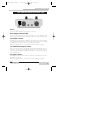
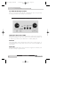
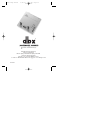
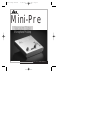
mini comp manual
8/16/01
1:48 PM
Page 1
®
Mini-Pre
Vacuum Tube
Microphone PreAmp
User Manual
mini comp manual
8/16/01
1:48 PM
Page 2
IMPORTANT SAFETY INSTRUCTIONS
WARNING FOR YOUR PROTECTION PLEASE READ THE FOLLOWING:
CAUTION
RISK OF ELECTRIC SHOCK
DO NOT OPEN
A T T E N T I O N : RISQUE DE CHOC ELECTRIQUE - NE PAS OUVRIR
W A R N I N G : TO REDUCE THE RISK OF FIRE OR ELECTRIC
SHOCK DO NOT EXPOSE THIS EQUIPMENT TO RAIN OR MOISTURE
The symbols shown above are internationally accepted symbols that warn of potential hazards with electrical products.
The lightning flash with arrowpoint in an equilateral triangle
means that there are dangerous voltages present within the
unit. The exclamation point in an equilateral triangle indicates that it is necessary for the user to refer to the owner’s
manual.
These symbols warn that there are no user serviceable parts
inside the unit. Do not open the unit. Do not attempt to service the unit yourself. Refer all servicing to qualified personnel. Opening the chassis for any reason will void the manufacturer’s warranty. Do not get the unit wet. If liquid is
spilled on the unit, shut it off immediately and take it to a
dealer for service. Disconnect the unit during storms to prevent damage.
NOTICE FOR CUSTOMERS IF YOUR UNIT IS EQUIPPED WITH A POWER CORD.
WARNING: THIS APPLIANCE MUST BE EARTHED.
CAUTION: EQUIPMENT IS NOT DISCONNECTED FROM MAINS WHEN SWITCH IS
IN THE OFF POSITION
The cores in the mains lead are coloured in accordance with the following code:
BLUE - Neutral
BROWN - Live
As colours of the cores in the mains lead of this appliance may not correspond with
the coloured markings identifying the terminals in your plug, proceed as follows:
• The core which is coloured green and yellow must be connected to the terminal in the plug marked with the letter E, or with the earth symbol, or
coloured green, or green and yellow.
• The core which is coloured blue must be connected to the terminal marked
N or coloured black.
• The core which is coloured brown must be connected to the terminal marked
L or coloured red.
This equipment may require the use of a different line cord, attachment plug, or
both, depending on the available power source at installation. If the attachment plug
needs to be changed, refer servicing to qualified service personnel who should refer
to the table below. The green/yellow wire shall be connected directly to the units
chassis.
CONDUCTOR
WIRE COLOR
Normal
L
LIVE
BROWN
N
NEUTRAL
BLUE
E EARTH GND GREEN/YEL
Alt
BLACK
WHITE
GREEN
WARNING: If the ground is defeated, certain fault conditions in the unit
or in the system to which it is connected can result in full line voltage
between chassis and earth ground. Severe injury or death can then
result if the chassis and earth ground are touched simultaneously.
2
WATER AND MOISTURE: Appliance should not be used
near water (e.g. near a bathtub, washbowl, kitchen sink,
laundry tub, in a wet basement, or near a swimming pool,
etc). Care should be taken so that objects do not fall and liquids are not spilled into the enclosure through openings.
POWER SOURCES: The appliance should be connected to
a power supply only of the type described in the operating
instructions or as marked on the appliance.
SAFETY INSTRUCTIONS
GREEN and YELLOW - Earth
KEEP THESE INSTRUCTIONS
HEED ALL WARNINGS
FOLLOW ALL INSTRUCTIONS
CLEAN ONLY WITH A DAMP CLOTH.
DO NOT BLOCK ANY OF THE VENTILATION OPENINGS.
INSTALL IN ACCORDANCE WITH THE MANUFACTURERS
INSTRUCTIONS.
DO NOT INSTALL NEAR ANY HEAT SOURCES SUCH AS RADIATORS, HEAT REGISTERS, STOVES; OR OTHER APPARATUS
(INCLUDING AMPLIFIERS) THAT PRODUCE HEAT.
ONLY USE ATTACHMENTS/ACCESSORIES SPECIFIED BY THE
MANUFACTURER.
UNPLUG THIS APPARATUS DURING LIGHTNING STORMS OR
WHEN UNUSED FOR LONG PERIODS OF TIME.
GROUNDING OR POLARIZATION: Precautions should be
taken so that the grounding or polarization means of an
appliance is not defeated.
POWER CORD PROTECTION: Power supply cords should
be routed so that they are not likely to be walked on or
pinched by items placed upon or against them, paying particular attention to cords at plugs, convenience receptacles,
and the point where they exit from the appliance.
SERVICING: To reduce the risk of fire or electric shock, the
user should not attempt to service the appliance beyond that
described in the operating instructions. All other servicing
should be referred to qualified service personnel.
FOR UNITS EQUIPPED WITH EXTERNALLY ACCESSIBLE FUSE RECEPTACLE:
Replace fuse with same type
and rating only.
MULTIPLE-INPUT VOLTAGE: This equipment may require
the use of a different line cord, attachment plug, or both,
depending on the available power source at installation.
Connect this equipment only to the power source indicated
on the equipment rear panel. To reduce the risk of fire or
electric shock, refer servicing to qualified service personnel
or equivalent.
POWER ON / OFF SWITCH: The Power Switch used in this
piece of equipment DOES NOT break the connection from
the Mains.
mini comp manual
8/16/01
1:48 PM
Page 3
IMPORTANT SAFETY INSTRUCTIONS
LITHIUM BATTERY
WARNING
CAUTION!
This product may contain a lithium battery.There is danger of
explosion if the battery is incorrectly replaced. Replace only
with an Eveready CR 2032 or equivalent. Make sure the battery is installed with the correct polarity. Discard used batteries according to manufacturer’s instructions.
ADVARSEL!
Lithiumbatteri - Eksplosjonsfare.Ved utskifting benyttes kun
batteri som anbefalt av apparatfabrikanten. Brukt batteri
returneres apparatleverandøren.
U.K. MAINS PLUG WARNING
A molded mains plug that has been cut off from the cord is unsafe.
Discard the mains plug at a suitable disposal facility. NEVER UNDER ANY
CIRCUMSTANCES SHOULD YOU INSERT A DAMAGED OR CUT MAINS
PLUG INTO A 13 AMP POWER SOCKET. Do not use the mains plug without the fuse cover in place. Replacement fuse covers can be obtained
from your local retailer. Replacement fuses are 13 amps and MUST be
ASTA approved to BS1362.
DECLARATION OF
CONFORMITY
ADVARSEL!
Lithiumbatteri - Eksplosionsfare ved fejlagtig håndtering.
Udskiftning må kun ske med batteri av samme fabrikat og
type. Levér det brugte batteri tilbage til leverandøren.
VAROITUS!
Paristo voi räjähtää, jos se on virheellisesti asennettu.Vaihda
paristo ainoastaan laitevalmistajan suosittelemaan tyyppin.
Hävitä käytetty paristo valmistajan ohjeiden mukaisesti.
VARNING!
Explosionsfara vid felaktigt batteribyte. Använd samma batterityp eller en ekvivalent typ som rekommenderas av apparattillverkaren. Kassera använt batteri enligt fabrikantens instruktion.
ELECTROMAGNETIC
COMPATIBILITY
This unit conforms to the Product
Specifications noted on the Declaration of
Conformity. Operation is subject to the following two conditions:
• this device may not cause harmful interference, and
• this device must accept any interference
received, including interference that may
cause undesired operation.
Operation of this unit within significant electromagnetic fields should be avoided.
• use only shielded interconnecting cables.
Manufacturer’s Name:
Manufacturer’s Address:
dbx Professional Products
8760 S. Sandy Parkway
Sandy, Utah 84070, USA
declares that the product:
Product name:
dbx Mini Tube Pre
Note: Product name may be suffixed by the letters EU, JA.
Product option:all (requires Class II power adapter that
conforms to the requirements of EN60065, EN60742, or
equivalent.)
conforms to the following Product Specifications:
Safety:
IEC60065 (1998)
EN 60065 (1993)
EMC:
EN 55013 (1990)
EN 55020 (1991)
Supplementary Information:
The product herewith complies with the
requirements of the Low Voltage
Directive 73/23/EEC and the EMC
Directive 89/336/EEC as amended by
Directive 93/68/EEC.
dbx Professional Products
Vice-President of Engineering
8760 S. Sandy Parkway
Sandy, Utah 84070, USA
June 7, 2001
European Contact:
Office or
Your Local dbx Sales and Service
Harman Music Group
8760 South Sandy Parkway
Sandy, Utah
84070 USA
Phone:(801) 568-7660 fax:(801) 568-7662
3
mini comp manual
Mini-Pre
8/16/01
1:48 PM
Page 4
Service Contact Information
Service Contact Information
If you require technical support, contact dbx Customer Service. Be prepared to
accurately describe the problem. Know the serial number of your unit - this is
printed on a sticker attached to the bottom of the unit. If you have not already
taken the time to fill out your warranty registration card and send it in, please do
so now.
Before you return a product to the factory for service, we recommend you refer
to the manual. Make sure you have correctly followed installation steps and
operation procedures. If you are still unable to solve a problem, contact our
Customer Service Department at (801) 568-7660 for consultation. If you need to
return a product to the factory for service, you MUST contact Customer Service
to obtain a Return Authorization Number.
No returned products will be accepted at the factory without a Return
Authorization Number.
Please refer to the Warranty below, which extends to the first end-user. After
expiration of the warranty, a reasonable charge will be made for parts, labor, and
packing if you choose to use the factory service facility. In all cases, you are
responsible for transportation charges to the factory. dbx will pay return shipping
if the unit is still under warranty.
Use the original packing material if it is available. Mark the package with the
name of the shipper and with these words in red: DELICATE INSTRUMENT,
FRAGILE! Insure the package properly. Ship prepaid, not collect. Do not ship
parcel post.
®
Mini-Pre User Manual
4
mini comp manual
8/16/01
1:48 PM
Page 5
Warranty Information
Mini-Pre
Warranty Information
This warranty is valid only for the original purchaser and only in the United
States.
1. The warranty registration card that accompanies this product must be mailed
within 30 days after purchase date to validate this warranty. Proof-of-purchase is
considered to be the burden of the consumer.
2. dbx warrants this product, when bought and used solely within the U.S., to be
free from defects in materials and workmanship under normal use and service.
3. dbx liability under this warranty is limited to repairing or, at our discretion,
replacing defective materials that show evidence of defect, provided the product
is returned to dbx WITH RETURN AUTHORIZATION from the factory, where all
parts and labor will be covered up to a period of two years. A Return
Authorization number must be obtained from dbx by telephone. The company
shall not be liable for any consequential damage as a result of the product's use
in any circuit or assembly.
4. dbx reserves the right to make changes in design or make additions to or
improvements upon this product without incurring any obligation to install the
same additions or improvements on products previously manufactured.
5. The foregoing is in lieu of all other warranties, expressed or implied, and dbx
neither assumes nor authorizes any person to assume on its behalf any obligation
or liability in connection with the sale of this product. In no event shall dbx or its
dealers be liable for special or consequential damages or from any delay in the
performance of this warranty due to causes beyond their control.
®
Mini-Pre User Manual
5
mini comp manual
Mini-Pre
8/16/01
1:48 PM
Page 6
Introduction and Features
Introduction and Features
Congratulations on your purchase of the dbx Mini-Pre! For 30 years, dbx has
been the industry leader in dynamics processing. With the introduction of the
MINI-PRE, we are now able to offer our superior dynamics processing technology
in a compact and affordable product design.
This manual will be your guide to understanding the full functionality of the MiniPre. After you have become familiar with the unit, we encourage you to experiment and find creative ways that the MINI-PRE can help you make a better sounding mix.
Mini-Pre Features•
•
•
•
•
•
•
•
•
•
•
•
Hand-Selected 12AX7 Pre Amp Tube
60 dB of Gain and -∞ to +10dB of Output Level
Input Gain Control
Output Gain Control
Phase Reverse
20dB Pad Switch
Selectable +48 volt Phantom Power
Balanced XLR Input and Output
Impedance-balanced 1/4” TRS Output
1/4” TS Input
Neutrik (locking) XLR connectors
SMT™ Technology
®
Mini-Pre User Manual
6
mini comp manual
8/16/01
1:48 PM
Page 7
Connections\Operation
Mini-Pre
Rear Panel Descriptions (from left to right)
Power Supply Connector
Connect the included PS 0913 power supply at this point.
Power Supply Cord Strain Relief
To prevent any untimely power supply interruptions, it is recommend that the
power supply cable be looped over the hook of the power supply cord strain relief.
XLR Output Connector
The XLR output of the Mini-Pre is balanced. The XLR output is ideal for running
from the Mini-Pre directly into the input of a XLR input of a mixing console. Note:
The XLR and 1/4” output connectors can be used simultaneously.
XLR Pin configuration: Pin 1 = Ground, Pin2 = Positive and Pin3 = Negative
1/4” Balanced TRS Output Connector
The 1/4” output connector of the Mini-Pre is impedance-balanced TRS. The 1/4”
output is ideal for running from the Mini-Pre directly into 1/4” inputs of mixing consoles and\or power amplifiers. Note: The XLR and 1/4” output connectors can be
used simultaneously.
XLR Input Connector
The XLR Input connector of the Mini-Pre is balanced. The XLR input is ideal for
microphone connections.
XLR Pin configuration: Pin 1 = Ground, Pin2 = Positive and Pin3 = Negative
®
Mini-Pre User Manual
7
mini comp manual
Mini-Pre
8/16/01
1:48 PM
Page 8
Connections\Operation
1/4” Balanced TRS Input Connector
The 1/4” input connector of the Mini-Pre is unbalanced TS. The 1/4” input is ideal
for running instrument cables directly into the Mini-Pre.
Front Panel Descriptions (from left to right)
Input Gain Control +24 to +60dB
Use the Input gain control to set the overall amount of input gain being fed into
the Min-Pre. Turning the Gain control clock wise will increase the gain from +24
to +60dB. Stages include: +24 to 60dB and +6 to +40dB (+20dB pad).
Peak LED
The red Peak LED is used to indicate that the input signal is severely clipping. It
is recommended that the Input Gain control be set so that the Peak LED occasionally lights.
Power LED
The green Power LED indicates that power has been supplied to the Mini-Pre, and
the unit is currently in operation mode.
®
Mini-Pre User Manual
8
mini comp manual
8/16/01
1:48 PM
Connections\Operation
Page 9
Mini-Pre
+48volt Switch
The +48 volt switch (pushed in) is used to supply power to any microphone that
requires +48volt phantom power.
+20dB Pad Switch
The +20dB Pad switch is used to select the desired gain range of the Mini-Pre.
When the switch is not depressed, the Mini-Pre is in normal +26 to 60dB mode.
When the +20dB Pad switch is pressed, the gain range of the Mini-Pre is +6 to
+40dB.
Phase Switch
The Phase switch of the Mini-Pre is used to adjust the phase output of the unit.
When the switch is depressed (out) the output is normal, or in phase. When the
Phase switch is engaged (pressed in), the output signal is out of phase.
Output Control -∞ to +10dB
The Output control of the Mini-Pre is used to set the overall output signal of the
Mini-Pre being sent to a receiving device. When the control knob is turned completely to the left, there is no output signal being sent to a receiving device.
Adjusting the control knob to clockwise, output signal is being increased. The
range is from -∞ to +10dB.
®
Mini-Pre User Manual
9
mini comp manual
8/16/01
1:48 PM
Mini-Pre
Page 10
Applications
Mini Tube Pre Applications
In addition to being designed specifically for portable desktop tube microphone
preamp applications, the Mini Tube Pre is also ideal to be used in numerous other
applications. These applications include the following:
Live Applications
The Mini-Pre is perfect for live vocal microphones and instruments. This is ideal
to use with a vocal mic’ or instrument to warm the tone that can sometimes be sterilized by mixing consoles.
Hard Disk Applications
You can also use the Mini-Pre as a direct interface for digital audio workstations.
The Mini-Pre is ideal because digital recorders are notorious for having sterile
sounding preamp sections.
The Mini-Pre as a direct box
You can also use the Mini-Pre as a direct interface for acoustic guitar applications.
Thanks to its portable chassis design, the Mini-Pre is the perfect tool for onstage
acoustic guitar applications.
®
Mini-Pre User Manual
10
mini comp manual
8/16/01
1:48 PM
Page 11
Mini-Pre
Specifications
Microphone Input
Connector:
Type:
Impedance:
Maximum Input Level:
CMRR:
Equivalent Input Noise:
Female XLR Pin 2 Hot
Electronically balanced/unbalanced
2kΩ
-10 dBu or +10 dBu with 20 dB pad engaged
Typically >80dB at 1kHz
Typically -125 typical dBu with a 150Ω source load
“A-weighted”
Line Input
Connector:
Type:
Impedance:
Maximum Input Level:
Gain
TS 1/4" Jack
Electronically unbalanced
>1 meg Ω
0 dBu or +20dBu with 20dB pad engaged
26dB to 60dB
Outputs
Connector:
Type:
Impedance:
Maximum Output Level:
Male XLR Pin 2 Hot and impedance balanced TRS 1/4"
Balanced/unbalanced
Balanced 600Ω, unbalanced 300Ω
(XLR) > +27dBu; (1/4”) > +21dBu
System Performance
Gain Control Range:
Output Level Control Range
Phantom Power:
PAD:
PHASE:
Frequency Response:
THD+Noise:
+26dB to +60dB for Mic Input
+16dB to +50dB for Line and Instrument Inputs
-∞ to +10dB
+48V
20dB pad
Reverses pins 2 and 3 of the output XLR
10Hz to 45kHz (-3dB points)
0.08% typical at -10dBu out, 1kHz, 30 dB gain
“A-weighted”
Power Supply
Operating Voltage:
JA:
DO:
EU:
100VAC 50/60Hz
120VAC 60Hz,
230VAC 50/60 Hz
Power Requirements:
9VAC 1300ma (12 watt typical power consumption)
®
Mini-Pre User Manual
11
mini comp manual
8/16/01
1:48 PM
Page 12
®
A Harman International Company
8760 South Sandy Parkway
Sandy, Utah 84070
Phone: (801) 568-7660 Fax (801) 568-7662
Int’l Fax: (801) 568-7583
E-mail us at: [email protected]
or visit our World Wide Web home page at: www.dbxpro.com
18-1304