1
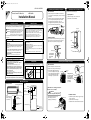
EN_3P214218-1.fm Page 1 Thursday, October 4, 2007 3:37 PM
3P214218-1 M07B111
Remote Control PC-Board Set
Removing and installing front panel
1)Place your fingers in the indentations on the main unit
(one each on the left and right sides), and open the panel
until it stops.
2)Continue to open the front panel further while sliding the
panel to the right and pulling it toward you in order to
disengage the rotating shaft on the left side. To
disengage the rotating shaft on the right side, slide the
panel to the left while pulling it toward you.
Safety Precautions
Outline/Features
• Read these Safety Precautions carefully to ensure correct installation.
This set is an interface that connects a wired remote controller to a
room air conditioner.
WARNING : Failure to follow WARNING is very likely to result in
such grave consequences as death or serious injury.
CAUTION : Failure to follow CAUTION may result in serious
injury or property damage, and in certain
circumstances, may result in a grave consequence.
Be sure to follow all the precautions below ; they are all important for
ensuring safety.
WARNING
• Starting and stopping the air conditioner and making mode and temperature
settings in the air conditioner through the wired remote controller (within a
range of 18˚C to 32˚C while in cooling mode, 14˚C to 30˚C while in heating
mode, but no temperature settings while in ventilation mode).
• Monitoring the operating conditions, occurrence of errors, and contents of
errors of the air conditioner through the wired remote controller.
• Restoring the operating condition of the air conditioner to the previous
condition at the time of power recovery in case of power failure.
Improper installation by yourself may cause malfunction, electrical shock, or fire.
• Install the set according to the instructions given in this manual.
Incomplete or improper installation may cause malfunction, electrical
shock, or fire.
• Be sure to use the standard attachments or the genuine parts.
Use of other parts may cause malfunction, electrical shock, or fire.
• Disconnect power to the connected equipment before
starting installation.
• Opening method
1)Remove the single screw of the service lid.
2)Pull out the service lid frontward.
Indentations on
the main unit
Service lid
• Installation method
Align the tabs of the front panel with the grooves, and push
all the way in. Then close slowly. Push the center of the
lower surface of the panel firmly to engage the tabs.
The set does not support the following functions.
• Installation should be left to the dealer or another qualified
professional.
The service lid is of removable type.
• Removal method
<KRP980B1>
Installation Manual
This manual classifies precautions into WARNING and CAUTION.
Opening service lid of indoor unit
• Group control (i.e., the control a number of indoor units through a single
remote controller)
• Monitoring of the following items:
Indoor temperature and operating conditions of thermo, compressor, indoor
fan, electric heater, and humidifier
• Control of the following items:
Forced thermo OFF, filter sign display and reset, and air-conditioner charge
management
• Energy-saving reference, low-noise reference, and demand reference
Screw
Rotating shaft
Push the rotating
shaft of the front
panel into the
groove.
Failure to do so may cause malfunction, electrical shock, or fire.
CAUTION
• An earth leakage circuit breaker should be installed.
If the breaker is not installed, electrical shock may occur.
• Do not install the set in a location where there is danger of
exposure to inflammable gas.
Gas accumulated around the unit at the worst may cause fire.
• To prevent damage due to electrostatic discharge, touch
your hand to a nearby metal object (doorknob, aluminum
sash, etc.) to discharge static electricity from your body
before touching this kit.
Components
Removing and installing front grille
Check that the set is provided with the following components.
Component
Quantity
Component
• Removal method
1)Remove front panel to remove the air filter.
Quantity
Upper hook
2)Remove the screws (2) from the front grille.
Main component
3)In front of the
mark of the front
grille, there are 3 upper hooks. Lightly
pull the front grille toward you with one
hand, and push down on the hooks
with the fingers of your other hand.
Static electricity can damage this kit.
• Lay this cable separately from other power cables to avoid
external electrical noises.
1
Installation Manual
1
• After installation is complete, test the operation of the PCB set to
check for problems, and explain how to use the set to the end-user.
Upper hook
Wiring
Mounting position of the set
Inside indoor unit
This set
Electrical
component box
S602
S601
<
When there is no work space because
the unit is close to ceiling
Option
BRC944A2B
>
CAUTION
S21
Be sure to wear protection gloves.
Flap
(in control of wind
directions upward
and downward)
Upper hook
Lightly pull the front
grille toward you with
one hand, and push
down on the hooks
with the fingers of your
other hand.
(3 locations)
Mounting Procedure
Mounting Position
Push
down.
mark area
(3 locations)
Place both hands under the center
of the front grille, and while
pushing up, pull it toward you.
Electrical
component box
S403
• Installation method
1) Push up.
1)Install the front grille and firmly engage the upper
hooks (3 locations).
2)Install 2screws of the front grille.
3)Install the air filter and then mount the front panel.
Mounting position
of the set
PCB of indoor unit
Note:
Wires indicated by
thick lines are
not provided to the set.
2) Pull toward you.
EN_3P214218-1.fm Page 2 Thursday, October 4, 2007 3:37 PM
Connecting electrical component (this set)
Removing electrical component cover
* Refer to the surface page for the removal of each part in detail.
1. Prepare the electrical component (this set).
Preparing the electrical component (this set).
Fig. 1
(See Fig. 1)
*1 Remove the front panel.
WARNING
*2 Remove the front grille.
*3 Remove the service lid of the indoor unit.
4 Remove the cover of the electrical component cover.
On completion of the connection of the
electrical component (this set), mount the
removed parts to the original positions.
1) Remove the electrical component cover
• Be sure to turn OFF the power at the time of
installation work.
Do not touch any electric parts with the power
turned ON. Otherwise, an electric shock may be
received.front panel.
of the set.
Electrical component
Remove the electrical
component cover.
Insert the cord
into the S403.
2) Insert the connection cord into the S21
connector (white) of the set.
Cut-outs
3) Route each connection cord through the
Disengage
the tab.
cut-out of the set and mount the electrical
Electric component cover
component cover to the original position.
4) Insert the connector of the set into the
S403 in the indoor unit electrical
*1
Route the connection
cord through the cut-out
(cut-out A).
component connector. Then route the
connection cord to the cut-out (cut-out A)
Electrical component box
in the indoor unit electrical component.
If there is a workspace on the right-hand side of
the indoor unit, the installation work can be
conducted without removing the electrical
component box.
Remove the tabs.
2. Mount the electrical component cover to
the original position. (See Fig. 2)
Electric component
cover
S21
Route each connection
cord through the cut-out.
*1 Connection cord cut-out
3. Mount the set. (See Fig. 2)
Cut-out A
S403 connection cut-out
1) Mount the set to the electrical component
box of the indoor unit.
Tab
Cut-out B
S403 connection cut-out
2) Route the connection cord as shown in
Mounting screw of electrical
component box.
Fig. 2 (Routing connection cord).
Cut-out C
Connection cord cut-out
Removing electrical component box
Installing electrical component
Fig. 2
If there is a workspace on the right-hand side of the indoor unit, the installation work can be conducted without removing
the electrical component box.
Install the electrical component cover
in its original position.
Install the electrical component.
Electric component cover
Place the connection cord to come
in contact with the protruding part.
1. Remove the flap (in control of wind directions upward and downward).
2. Disconnect the communication wiring (see Fig. 1).
3. Disconnect the S200 connector (see Fig. 2).
On completion of the connection of the
electrical component (this set), mount the
removed parts to the original positions.
4. Disconnect the heat changer from the thermistor (see Fig. 3).
Connection cord
5. Remove the mounting screw of the electrical component box, and remove the electrical component box (see Fig. 1).
Fig. 1
Positions of communication wiring and mounting
screw of electrical component box
Protruding part
Fig. 2
Position of each
connector
Fit in.
Electrical component
Fig. 3 Position of thermistor
Routing connection cord
Push the electrical component until it
snaps into engagement with the tab.
S200
Thermistor
S403 connection cord
Communication
wiring
Connection cord
Make sure that the mounting bracket
of the thermistor will not fall off.
Flap
Mounting screw of electrical
component box
Tab
3P214218-1