1
MONITOR AFx™ Director
User's Guide
V4.1
Contents
Using this Guide..................................................................................................................................... iv
Welcome .....................................................................................................................................................1
Introduction to Security Management .....................................................................................................2
Entering an Area & Disarming the System..............................................................................................7
Welcome to MONITOR AFx™ Director...................................................................................................8
Startup and Logging In.................................................................................................................8
Exiting, Logging Off, or Changing Operators..............................................................................10
The Desktop...............................................................................................................................12
System Management Primer ................................................................................................................14
Monitoring Activity, and Running Reports ............................................................................................17
Monitoring System Activity....................................................................................................................18
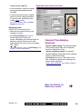
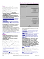
Visually Verifying Users (Photo-Verification).........................................................................................24
Photo-Verification.......................................................................................................................24
Setting up This Feature..............................................................................................................25
Time-and-Attendance Reporting ...........................................................................................................26
Required-Attendance Time-Periods ...........................................................................................30
Reporting on System & Personnel Activity............................................................................................32
Reporting on Previous Guard-Tours .....................................................................................................36
Reporting on User Access Authorities (by Area, Door, or Floor)...........................................................38
Reporting on Users, System/Device Settings, etc.................................................................................40
Reporting on Operator Audits or Panel Communications Logs.............................................................42
Working with the Report Viewer............................................................................................................44
Checking Status and Controlling Items .................................................................................................45
Guard-Tours .........................................................................................................................................46
Introduction to Guard Tours .......................................................................................................46
Activating and Monitoring Guard Tours (that have already been set up) ...................................48
Setting up (Configuring) Guard Tours ........................................................................................50
Maps and Video (Visual Monitoring & Status/Control) ..........................................................................52
Status and Control Using Visual Director ...................................................................................52
Controlling a Pan/Tilt/Zoom Camera..............................................................................55
Initial Set Up of Views and Maps ..........................................................................................................58
Checking Status & Controlling Items.....................................................................................................64
Introduction to Status & Control .................................................................................................64
Using the Status Toolbar............................................................................................................66
Panel Date and Time .................................................................................................................68
Resetting Users' Antipassback Status........................................................................................70
Checking the Status of Panels (Equipment)...............................................................................72
Checking the Status of Modules.................................................................................................74
Checking the Status of a Suite Security System ........................................................................76
Checking Status or Controlling Items by Area............................................................................78
Checking Status or Controlling Individual Doors ........................................................................82
Checking Status or Controlling Elevators ...................................................................................84
Checking Status or Controlling Floors ........................................................................................86
Checking Status or Bypassing Input Points (Sensors) ...............................................................88
Panel Communications and Updates....................................................................................................90
Panel Communications ..............................................................................................................90
Activating Communications and Transferring Panel Settings.....................................................92
Viewing the Status of Previous Communications Sessions........................................................98
500-9041 v4.1 (2002.09)
© 2002 CSG Security Inc. / Sécurité CSG Inc.
i
Correcting Communication/Update Errors ............................................................................... 100
Setting Communications to AutoStart when an Operator Logs In (Single-PC Systems) .......... 102
Administration and Maintenance.......................................................................................................... 105
Operators (People Who Can Use This Software) ............................................................................... 106
Changing an Operator's Password .......................................................................................... 108
Operator Permissions .............................................................................................................. 110
Schedules for User-Access and Area Automation .............................................................................. 114
Holidays and Time-Change Dates ...................................................................................................... 118
Users (Entrants / Panel Users) ........................................................................................................... 120
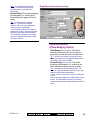
The Photo-Badging Option.......................................................................................................124
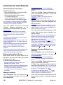
Authorities for Users/Entrants .................................................................................................. 128
Custom Information Categories for Users (Custom User Information) .................................... 134
Fall-Back Users (Can Enter During Comms Failure)................................................................ 136
System Maintenance Tasks................................................................................................................ 138
Password and Personal ID Number (PIN) Issues .................................................................... 138
Large Systems--Checking for Software vs. Panel Differences / Conflicts ................................ 140
Client/Server Systems: Checking to See Who Else is Logged onto the Database ................ 141
Checking / Repairing the MONITOR AFx Director Database Tables ....................................... 142
Backing up or Restoring the Database..................................................................................... 144
Exporting or Importing Activity or Audit Logs (Archive) ............................................................ 148
Removing old Activity or Audit Logs (Purge)............................................................................ 150
System Configuration............................................................................................................................ 151
Accounts and Account Folders (Multi-Account Systems) ................................................................... 152
Account-Wide Panel Settings (Feature-Set, Service PIN, etc.)........................................................... 154
Site/Account Location and Contact Information ....................................................................... 157
Alarm / Event Instructions ........................................................................................................ 158
Enabling Sounds (to be associated with event/alarm messages) ............................................ 160
Customizing How Events are Displayed (Event Priority).......................................................... 162
Panels, Panel Groups, and Connection Settings ................................................................................ 164
System Settings for each Panel.......................................................................................................... 170
System Security Settings for a Panel ....................................................................................... 170
Monitoring, Paging, & Remote Mgt. Settings ........................................................................... 172
System Card-Access Settings.................................................................................................. 176
Equipment Settings (Pseudo / Internal Inputs)......................................................................... 178
Understanding Access-Controlled Areas ............................................................................................ 180
Areas and Related Settings ................................................................................................................ 182
Expansion Modules ............................................................................................................................ 186
Suite-Security Keypads and Related Settings .................................................................................... 190
Doors, Readers, and Related Settings ............................................................................................... 194
Reader 1 & 2 Settings for a Door ............................................................................................. 198
Defining a ‘Required Attendance’ Zone ....................................................................... 198
Elevators (Lifts) and Associated Readers ........................................................................................... 202
Floors (Pertaining to Access-Controlled Elevators / Lifts) ................................................................... 208
Input Points—Monitored Sensors ....................................................................................................... 210
Input Points—Pre-Defined Sensor Types ................................................................................ 213
Input Points—Custom Point Types .......................................................................................... 214
Programmable Outputs (Signalling & Device-Switching) .................................................................... 218
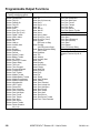
Programmable Output Functions ............................................................................................. 220
ii
MONITOR AFx™ Director V4.1 User's Guide
500-9041 v4.1
Installation and Technical Reference ...................................................................................................221
PC Issues and Software Installation ...................................................................................................222
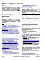
Welcome ..................................................................................................................................222
Recommended Computer Specifications .................................................................................222
Serial Port Installation and Set Up ...........................................................................................224
Windows Settings Required .....................................................................................................224
"Open Database" Option: User 'Logins' and Passwords: ........................................................225
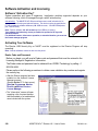
Software Installation for a Fresh/New System..........................................................................226
Upgrading from an Earlier Version of Software ........................................................................228
If You Need to Transfer the Database to a Different PC..............................................231
DCOM Setup (Required for Client-Server MONITOR AFx Director Systems):.........................232
Client/Server Start-up Issues ..............................................................................................................236
Software Activation and Licensing ......................................................................................................238
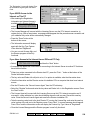
Activating Your Software ..........................................................................................................238
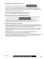
Upgrading Your Software (Adding Optional Features) .............................................................240
Client / Server Setup (Allowable Client List) .......................................................................................242
New Installation? Try the Wizard ! .....................................................................................................244
Panel Connection Overview................................................................................................................245
IP Connectivity .........................................................................................................................246
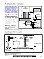
PC-to-Panel—Direct Connection..............................................................................................247
PC and Panels—Modem Connections .....................................................................................249
Serial Port / Modem Setup (Communications Software) ..........................................................254
Communication Pools for System Panels ................................................................................258
Setting Up a New System (Commissioning) .......................................................................................260
Customizing the MyTools Bar .............................................................................................................266
System Capacities ..............................................................................................................................269
Advanced Database Features ............................................................................................................275
The "Open Database" Feature (SQL Server) ...........................................................................275
User-Logins (Needed for: Database Query, and Open Database)..........................................276
Linking to the Database (Used for: Custom Query/Reporting; ERM Integration) ...................278
Automated User-Import (Used for: ERM Integration) ..............................................................282
Manually Importing User-Data From a Text File.......................................................................284
System / Hardware Reference............................................................................................................285
Desktop Reference .............................................................................................................................288
The Desktop.............................................................................................................................288
The Menu .................................................................................................................................290
The Toolbar..............................................................................................................................293
The Monitoring Window and Status Bar ...................................................................................295
The Tree Area (and 'right-click' menu) .....................................................................................296
The MyTools List / Bar .............................................................................................................299
The Forms View (and 'right-click' menu) .................................................................................300
The Grid View (and 'right-click' menu).....................................................................................302
Other Desktop Choices ............................................................................................................304
Index........................................................................................................................................................307
500-9041 v4.1 (2002.09)
© 2002 CSG Security Inc. / Sécurité CSG Inc.
iii
Using this Guide
Each topic that pertains to a specific
MONITOR AFx™ Director screen generally
shows how to do things on the left, and what
the available settings mean on the right. This
may pertain to a single page, or sets of 'facing
pages' as required for larger topics. A bold
double-line marks the end of each 'How-To'
section, and the 'selection-descriptions' for the
present screen follow thereafter.
Use the table of contents (at the front), or the
index (at the back) to find a desired topic. The
table of contents shows the topics as they
appear in each chapter, while the index lists
topic keywords alphabetically.
Tip: The bottom of each right-hand page shows you
which chapter you are presently 'in'. (These match the
topic-buttons across the top of the on-line help.)
To find specific information within a topic, skim
through the subheadings (on the left), or the
selection-descriptions for the specific screen
(on the right) to find what you're looking for.
Tip: Additional notes, and links to other applicable
sections are provided throughout. You can typically
avoid reading the note text unless you run into
problems or otherwise feel that you need more
information.
On-Line Help Tip: The on-line help is structured in the
same basic format as this User's Guide, with topic
buttons that match the chapters and navigation footers
in this guide. As you refer to the User's Guide, you are
already becoming familiar with the on-line help (and
vice-versa).
Copyrights and Trademarks
™ MONITOR AFx Director, G-Prox, and
Netvision are trademarks of CSG Security Inc. /
Sécurité CSG Inc.
™ Pentium is a trademark of Intel Corporation
™ ® Microsoft, MS-DOS, Windows, Windows98,
Windows NT, Windows 2000, and Windows XP,
are trademarks or registered trademarks of the
Microsoft Corporation.
© Copyright 2002
CSG Security Inc. / Sécurité CSG Inc.
All rights reserved.
Disclaimer
All software, firmware, drawings, diagrams,
specifications, catalogues, literature, manuals
and other supplied materials shall constitute
the
proprietary
information
of
the
manufacturer. In the interests of ongoing
improvement in quality and design, we reserve
the right to change product specifications
without prior notification.
Attention: Physical alteration of hardware
components or removal of electrical devices
may void warranties, and/or affect radiofrequency and electromagnetic emissions.
This document is not to be copied, decompiled, or re-distributed in any form without
prior written consent.
© Copyright 1995-2002 CSG Security Inc. /
Sécurité CSG Inc.
iv
MONITOR AFx™ Director V4.1 User's Guide
500-9041 v4.1
Welcome
500-9041 v4.1
Welcome
Report
Control
Admin
Sys Config
Tech-Ref
1
Introduction to Security Management
General Concepts and Features
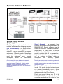
Seamlessly Integrated Security
The MONITOR AFx Director software provides
a seamless integration between managing
system security and controlling personnel
access at the facility. This provides assurance
that unauthorized access will be detected for
immediate attention, while allowing authorized
persons to enter at their designated doors and
times without triggering an alarm.
Feature-Rich Security
The monitoring of doors, windows, and areas
within the facility can be uniquely customized
to meet even the most stringent requirements
for a wide array of applications and situations.
The interweaving of characteristics for 'areas'
and individual devices, in conjunction with
authority assignments for groups of persons
provides a feature-rich environment for
monitoring activity, maintaining security, and
managing personnel.
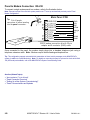
Access Control (Door and Elevator Controllers)
In its simplest sense, access control is the
management of WHO can go WHERE and
WHEN. With the addition of door (and/or
elevator) controller modules, user-access can
be controlled throughout a facility as desired.
Persons authorized to enter the facility are
(typically) given an access card or token,
which will allow access only to specific doors
at applicable times as per the person's
assigned authority profile. Each reader may
require entry of a PIN, and/or the presence of
an assigned escort (escort mode) or any
second valid user (dual custody) before the
door will unlock. Alternatively, entry can be
using a 4-10 digit number associated with each
person. Note: For access cards to be supported in
this case, the encoded card numbers must match this
value.
and area(s) can be set to disarm automatically
whenever specific persons are granted entry.
Elevator controllers provide an interface
between a reader in an elevator cab (lift), and
the floor 'call buttons'--allowing persons to
access only the floors that have been assigned
to them. Call buttons for specific floors can
also be activated based on a schedule-allowing anyone to access these floors during
specific days and times.
Visitors (and others) can: • Be given cards
that expire on a specific date and time;
• Be denied access unless accompanied by an
escort; • Have their card disabled when they
'badge' at a specific reader.
Activity Monitoring and Signalling
Activity that occurs at each site can be viewed
through the MONITOR AFx Director software,
and can also be transmitted to a Central
Monitoring Station.
The MONITOR AFx
Director monitoring window can be set to show
activity by date&time only, or all 'unresolved'
(and higher priority) events first. As well, the
window can be set to show all activity, or only
specific types of events (this is remembered
for each operator).
Events can be customized as to how they will be
displayed (priority, sound, colour, etc.). The event
log can be purged or archived to improve reporting
speed. With the archive feature, messages can be
re-imported when a report is needed on a date-range
that is no longer retained in the primary database.
How sensors are monitored--and events signalled, is
based on the settings for the specific device and its
associated "area", in conjunction with the arming
level that is presently in effect for each individual
area.
Dial up panels (with dedicated modems) can be set
to automatically dial-in and transfer alarms, or blocks
of activity messages to the MONITOR AFx Director
system. In other configurations, the alarms and
events are transmitted when a connection is made
with the specific panel(s)—either manually, or at
scheduled times.
Doors can also be set to unlock and re-lock or
change operating characteristics automatically
at desired times. Area characteristics can also
be automated based on a desired schedule,
2
MONITOR AFx™ Director V4.1 User's Guide
500-9041 v4.1
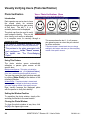
Photo Verification
Each operator can set a door to have the
stored photo for entrants displayed each time
someone gains access at that door. The last
1, 4, or 9 entrant's photos can be displayed.
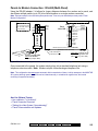
Centrally Monitored Systems
Centrally-monitored systems are connected to
a 24-hour ULC listed Monitoring Station for a
quick response when needed. When the
control panel detects an intrusion, fire, panic or
other alarm, it automatically signals the
Monitoring Station.
Emergency Response
Operators will notify the appropriate local
authorities in the area. Where by-laws require,
alarms will be verified before dispatch occurs.
A local alarm on your premises may not be
enough to scare away some intruders, so most
experts agree that a monitored system is a
required deterrent. As well, only a centrally
monitored system can provide this extra
measure of protection in the event of fire and
other emergencies.
Messages are transmitted to a monitoring station via
the 'Bell 103' (300 baud) modem/dialler built into
each main panel, and/or an IP connection (SIP
Reporting), or high-security communications (HSC).
(HSC is supported via Mark7 / DVACS service in
Canada). HSC modules also support a printer. SIP
Reporting is supported beginning with V3.30
MONITOR AFx Director software and panel firmware.
Photo Badging Feature (Optional)
With the optional photo-badging feature,
personnel photos can be captured directly in
the screen for each specific user, and then
printed onto the card when desired (along with
selected data). You can also design the layout
of elements to be printed onto the cards--for all
users, or have different designs for specific
blocks of users.
For details on supported video-capture devices and
card printers, refer to "For the Card Badging Option"
under "PC Issues and Software Installation".
500-9041 v4.1
Welcome
Report
Control
Maps and Live Video (Optional)
Beginning with V4.0, MONITOR AFx Director
includes a customizable visual interface for
viewing live cameras, monitoring alarms, and
controlling items.
We call this "Visual
Director".
Camera-viewing is supported through Netvision™
capture-stations.
Guard Tours
The routes taken by Guards can be initially set
up, and then monitored for a specific user
(guard) at any time. Each 'tour' will consist of
chosen
access-controlled
doors,
plus
additional guard tour stations (checkpoints)
that my be key-switches, or other types of
input points—along with the acceptable time
for the guard to arrive at each location.
Reporting
No security management system would be
complete without the ability to generate
reports. The MONITOR AFx Director software
provides an extensive list of customizable
reporting features, including: • Various Time
and Attendance reports; • Guard-Tour reports;
• Activity reporting (including Who went Where
and When); • User-access reports showing
persons who can access a specific area, door,
or floor during certain days and times;
• Printouts of the users and configured settings
for a specific account; • A record of changes
made by operators (audit reports).
These reports can be viewed and/or printed,
and many can be saved as a text file, or
archived in a viewable format.
Paging
The paging feature of MONITOR AFx Director
allows the triggering of certain outputs (up to
12 separate outputs per panel) to automatically
send a message to a numeric pager, letting the
wearer know that a certain event has occurred
(e.g., forced entry, communication failure, fire,
etc.). The specific events to be notified though
the pager can be customized as desired
through
the
programmable
outputs
configuration.
Admin
Sys Config
Tech-Ref
3
Device Control
Items can be controlled both by an authorized
user at an alarm keypad, and by an operator
using the MONITOR AFx Director software.
Some examples include bypassing sensors,
arming and disarming areas, and unlocking or
re-locking doors, or changing the operating
characteristics for doors (by 'area', or for
individual doors).
Actions can also be
scheduled to occur automatically at desired
times, or when a specific event occurs (such
as when an area is disarmed, or when a fire
alarm occurs, etc.).
Special-Use Features
A number of features are provided for special
applications, including:
• Visitors that Must be Escorted: Cards can
be set as 'escort-required'. This allows
tracking the movement of visitors, while
ensuring they cannot access controlled
areas without an escort.
• Card-Disable Readers: One reader can be
set to disable specific types of cards (e.g.
'escort required', 'temporary', etc.) instead of
causing a door to unlock.
• Master Override: A security officer can be
given the authority to enter doors that would
normally deny access (i.e., due to cards
being locked out, wrong time, etc.).
Exceptions: This will not override 'wrong area or
floor', card/PIN mode, 'strict APB', or door 'interlock'
issues.
• Panic Token: Wireless (RF) panic tokens
allow for locally or centrally-monitored
personal protection.
• Wandering Patient Control: Patients can be
equipped with 'smart' wristbands, allowing
their presence to be detected as they
approach exterior doors, or other locations
that may be of concern. An alarm can be
triggered, and the door can optionally lock as
the patient approaches. Specific staff
members can be given the authority to
cancel the alarm by presenting their token at
the specific door.
• Special Types of Input-Points: In addition to
allowing input-point monitoring to be fully
customized as desired, custom input-point
types can be set up to support
garage/extended-delay sensors, vault/safe
inputs, arm/disarm keyswitches, Guard-Tour
station inputs, and work-late buttons.
• Support for Suite-Security Keypads:
Depending on software licensing, up to 60
suite-security keypads with LED display are
supported per system panel, with 8 users
supported per suite/facility.
• Multiple-Tenant Support: User authorities
can be limited to working with a specific
range of users and user authorities. This
allows a multi-tenant facility to be managed
through a single system.
• High-Security Areas and Vault Auto-Arming:
Areas can be 'interlocked' so only one of
them can be disarmed at a time. Vault/safe
areas can be auto-armed when an attendant
closes the door.
• Door Interlock: Doors can be set to disallow
user access until up to 3 other specific doors
have been closed (and relocked) for a
specific period of time. This allows limiting
the number of persons who can enter in
close proximity, and/or the speed at which
persons can enter a specific area.
4
MONITOR AFx™ Director V4.1 User's Guide
500-9041 v4.1
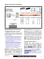
System Components and Software
System Software and Licensing
The MONITOR AFx Director Software
The MONITOR AFx Director software provides
a familiar Windows interface supporting these
easy-to use features:
• An authorized technician (service user) can configure
all aspects of the system for desired operation;
• Authorized administrative personnel have the ability
to easily manage personnel, monitor activity, and
perform typical maintenance tasks during the day-today operation of the system.
• Access to specific status and control features is
provided to authorized operators with applicable user
authorities, providing up-to-the-minute status and
manual-control ability on an area-by-area basis, or
for individual doors or sensors (input points).
• The software can be run on a single-PC, or across
multiple PCs in a client-server arrangement.
MONITOR AFx Director is compatible with
MONITOR AFx alarm systems—which in turn
support many types of expansion modules and
related hardware.
The MONITOR AFx
Director software (and the on-line help) run
under Windows9x/Me and Windows NT/2000.
500-9041 v4.1
Welcome
Report
Control
Easy to Set Up (Wizards and Tabbed Screens)
Beginning with V4.0, the MONITOR AFx
Director interface has been simplified to show
only the settings that apply to your installation
(per licensing, and account-type selections),
and screens have been neatly divided into
digestible topic-groupings. As well, the new
Tools menu includes handy Wizards that
provide a quick and easier way to set up a new
system, and enable panel communications.
Advanced Database Features
MONITOR AFx Director
provides
an
automated user import feature--allowing it to
be interfaced with a personnel management
system (Also called: "Enterprise Resource
Management").
Additionally, an "opendatabase" option allows your company's SQL
Server folks to take charge of the database.
Automated User Import: ≥V4.10 Director software with
"Elite+" licensing (Advanced Features).
Open Database: ≥V4.10 MONITOR AFx Director with
"Elite" or "Elite+" licensing (database query / advanced
features).
Admin
Sys Config
Tech-Ref
5
Customizable Desktop
The MONITOR AFx Director interface can be
set as desired by each individual operator.
This includes whether they prefer the MyTools
bar, or the Tree window, plus the sizing of the
desktop sections, and other settings. (The
MyTools bar can also be totally customized as
to the items it contains, what each item is
called, and the order (sequence) of the items.)
As well, the desktop will show only the features
and items that are available to each specific
operator (as per their assigned permissions).
Software Licensing and Activation Key
System capacities and types
of expansion / application
modules supported depends
on the software version and
licensing, which is managed
through the small 'activation key' provided with
the software.
Activation Key: The MONITOR AFx Director software
uses a small 'activation key' to manage software
licensing and optional features. This device must be
plugged onto the PC that contains the software
database (≥V4: USB connector; ≤V3.3.2:
Parallel/printer port; V3.3.3: Either).
Note: Director software ≥V4 will not start up if the
USB key is missing.
Software/Feature Activation: Refer to "Software
Activation and Licensing" to enable your software and
related capacities.
Multi-Language Support
The MONITOR AFx Director software supports
multiple languages including: English, French,
Spanish, Dutch, Russian, Simplified Chinese,
and Traditional Chinese.
Operators and users can then be set as to
their preferred language—allowing operator
screens, on-line help, and/or LCD-keypad
screens to appear in the appropriate language
for the person who is presently logged in.
Some of the capacities that follow also require
additional panel memory to be installed.
System upgrades may involve a combination
of upgrading software, hardware, and/or
licensing (refer to the instructions provided with
the upgrade kit).
Note: LCD keypads support English, French, Spanish,
and Dutch.
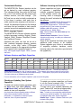
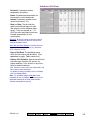
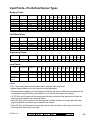
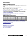
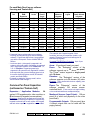
Software Versions and Basic Capacities
License
PCs;
COM
LAN (C/S) Ports
Accounts Doors
x Panels /pnl; /acnt
Modules; Elev.(Lift); Users;
Suite kypd Floors
Auth. Lvls
Prime
1; No
1
1x1
16; 16
24; 0 /panel 0; 0
1000; 100
Enterprise
8; Yes
3
10 x 60
32; 1920
24; 60
"
32; 124
4000; 100
Elite ≥v4.1 8; Yes
3
100 x 60
32; 1920
24; 60
"
32; 124
64000; 1000
Elite+ ≥v4.1 8; Yes
3
1000 x 60 32; 1920
24; 60
"
32; 124
64000; 1000
Maps & Photo
Video Badging
–
DB Query Auto
Open-DB (ERM)
–
–
–
Optional
–
–
–
Notes and Exceptions: • Adding panels allows for more areas, sensors, doors, etc.; • Elevator (lift) capacity is
shared with the door capacity--max. 32 total (per panel); • Floor capacity is the same per panel or account (124),
and can be for one building, or shared across multiple buildings; • Suite capacity is per panel, and is reduced by
5 for each (other type of) hardware module present.
For more information, refer to "System Capacities" (near the end of this guide).
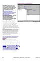
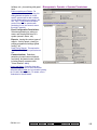
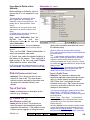
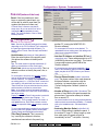
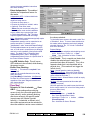
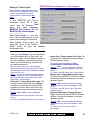
Checking or Updating Your System
Capacities
To check your present system capacities, open
the Help menu, and select [About]. Then,
click [License Info], and scroll within the small
window to view your capacities.
(Any three-letter acronyms typically pertain to different
types of door-controller modules, and other
peripherals.) For full details on maximum system
capacities, refer to "System Capacities".
6
-----------------------------------------------------------To update your system capacities, you'll need
to run the license manager utility. For details,
refer to "Software Activation and Licensing".
To make use of your available capacities, the
panel "Feature-Set" must be set appropriately.
For details, refer to "Account-Wide Panel Settings".
Note: To enable your new capacities, additional panel
memory may need to be installed. For details, refer to
the applicable table under "System Capacities".
Related Topic: "System / Hardware Reference" (near
the back of this guide).
MONITOR AFx™ Director V4.1 User's Guide
500-9041 v4.1
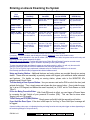
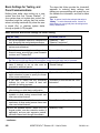
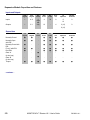
Entering an Area & Disarming the System
Reader/Door Mode
Area
Setting
Disarmed (Off)
Locked &
Card Only
Locked &
Card+PIN
Present card,
open the door
Locked &
Card or UID/PIN
Locked &
UID/PIN Only
Present card, enter PIN
open the door
Present card or enter
user no., enter PIN
open the door
Enter UID+PIN (or PIN
only), open the door
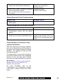
Armed & 'Auto
Disarm on Valid
Token'
Present card,
open the door
Present card, enter PIN
open the door
Present card or enter
user no., enter PIN
open the door
Enter UID+PIN (or PIN
only), open the door
Armed & 'PINOnly' or 'ID+PIN'
Present card, open the
door. Then log into
panel and disarm it.
Present card, enter PIN
open door. Then log
into the panel & disarm
it.
Present card or enter
user no., enter PIN
open door. Then log
into the panel & disarm
it.
Enter UID+PIN (or PIN
only), open the door.
Then log into panel and
disarm it.
Armed &
Dual Custody
Present card, open the
door. Then login with
two user PINs (or
ID+PIN), & disarm
area.
Present card, enter PIN
open door. Then login
with two user PINs (or
ID+PIN), & disarm
area.
Present card or enter
user no., enter PIN
open door. Then login
with two user PINs (or
ID+PIN), & disarm
area.
Enter UID+PIN (or PIN
only), open the door.
Then login with two
user PINs (or ID+PIN),
& disarm area.
If the door is unlocked, access is not controlled (simply open the door to enter the area).
Conversely, if the door is locked, and all cards are presently 'locked out', users will be unable to enter.
Card Number: As an alternative to the user ID number (UID), and/or access cards, the system can be set for entry and
login using the card number instead (4-10 digits).
Visitors that must be Escorted: Persons with a card set as "Visitor (Excort-Required)" must be escorted at each
controlled reader (valid escort or regular cardholder--depending on the system settings).
To enter at a controlled door and disarm the area, an entry delay must be in effect. As well, only the users with
authority to both enter the door at this time AND disarm the area will be granted entry.
The 'ID + PIN' or 'PIN Only' login requirement is determined by the 'Feature-Set' selection for the account.
Dual Custody (and Escort mode) is supported at individual readers as well.
Using an Arming Station: Additional features and entry options are provided through an arming
station. These units are essentially a proximity reader with keypad, plus additional status indicators
and features. For details on using an arming station, please refer to the MONITOR AFx
(panel/keypad) User's Guide.
To Enter using a Door-Opener Button: Use your access card and/or PIN to unlock the door (and
activate the button). Then, simply press and release the door-opener button. Once inside the area,
'log' in at an LCD keypad, and disarm the area if required (i.e., if NOT set for "Auto-Disarm on Valid
Token").
If You are Being Forced to Enter: With Card+PIN mode in effect, you can trigger a 'Duress' alarm
by reversing the last 2-digits of your personal ID number (PIN). This can also be done when
'logging' into an LCD keypad.
To Exit Using an RTE (REX) Button: Simply press and briefly hold the request-to-exit button.
If you Hold the Door Open: If the door is held open for 'too long', a 'Door Held Open' message will
be logged.
A person holding a door open, or indicating that they are being forced to enter may also trigger an alarm (depending on
the monitoring settings for the specific door).
500-9041 v4.1
Welcome
Report
Control
Admin
Sys Config
Tech-Ref
7
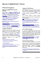
Welcome to MONITOR AFx™ Director
Startup and Logging In
Starting the MONITOR AFx Director
Software
Select Start, Programs, MONITOR AFx
Director V4, and MONITOR AFx Director,
and wait for the start-up screen to appear.
Activation Key: The MONITOR AFx Director software
uses a small 'activation key' to manage software
licensing and optional features. This device must be
plugged onto the PC that contains the software
database (≥V4: USB connector; ≤V3.3.2:
Parallel/printer port; V3.3.3: Either).
Note: Director software ≥V4 will not start up if the
USB key is missing.
Client/Server Systems: Take care to ensure that the
MONITOR AFx Director software is not already running
before attempting to start it. Troubleshooting Tip: If the
desktop is acting strangely, you may have two copies of
the software running (and you've run out of memory).
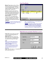
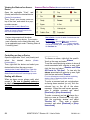
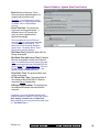
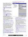
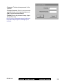
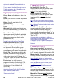
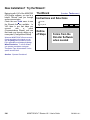
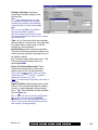
Logging In (Single-PC)
To gain access to your assigned items and
features, you must first perform a 'Login':
Select Login from the toolbar, and then enter
your name and password, pressing Tab in
between. Then, press Enter, or click Login.
If asked whether you want the "Communication
Application" started or not, select Yes
(typically).
Panel communications are required to:
• Update the monitoring window (live/real-time);
• Perform status & control tasks;
• Monitor guard-tours;
• Update panel(s) with changes.
Any previously active communications sessions (set to
"stay connected") will attempt to reconnect
automatically, once communications services are
running.
Logging In (Client/Server)
Select Login from the toolbar, and then enter
your name and password, pressing Tab in
between. (Ensure the "Server Location" is set
as well, if present.) Then, press Enter, or click
Login.
If a "Cannot Connect to Server" screen
appears, check that you have not mistyped the
"Server Location".
Note: The Director-server PC and software must be
running (this is the PC that includes "...DirectorServer.exe", and typically contains the database as
well. For additional things to check, refer to
"Client/Server Start-up Issues" (near the back of this
guide).
If you just upgraded for client/server (server location
missing on login screen): You may need to login once,
shut down the software (incl. the communications or
server module), then start the software and login again.
On-Line Help Language
For versions of MONITOR AFx Director that
include multi-language help files, the on-line
help will normally come up in the language
associated with your operator settings. You
can also select a different language-version if
desired (for this work-session).
Selecting a Different Help Language: Open the Help
menu, select Language, and then select from the
available choices.
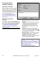
The Auto-Lockout Feature
If you do not use your keyboard for a specific
period of time, the software will automatically
go into 'lockout' mode to protect against an
unauthorized person viewing or changing
items. (For details, refer to the [Lockout]
description).
To set the period of time before the keyboard lockout
will occur (when you are logged in), refer to the section
on "Operators".
8
MONITOR AFx™ Director V4.1 User's Guide
500-9041 v4.1
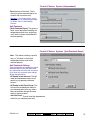
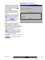
- Name: A valid operator's name.
- Password: The operator's assigned
password.
Default Operator Name & Password:
Operator, 1234
The default login name and password take effect
only until changed by a system administrator.
To protect against unauthorized access to the
software, the default password should be
changed right away.
If your login name and password are no longer
supported after upgrading from an earlier
software revision, refer to "Upgrading from an
Earlier Version of Software", paying special
attention to converting your previous database.
- Server Location: In a multi-PC (clientserver) installation, this allows you to
identify the MONITOR AFx Director server.
Select (or type in) the server "PC name" (or
its network "IP address").
Director-Server PC: This is the PC that includes
"...Director-Server.exe", and typically contains
the database as well.
This is typically entered once, and left as-is. The
initial default is your present PC. You can get
the actual value from your system administrator,
or 'browse' for the server PC on the network.
You can also go to that PC and check its
"Computer Name":
On the server PC, right-click Network
Neighborhood on the Windows desktop, select
Properties, and then the Identification tab.
To login at the server PC itself, use the PC
name (not the IP address).
(Single-PC, set to Auto-Start/Stop
Communications)
------------------------- [Login]: If the entered name and password
are valid, the operator will be provided
access to the items and features as
assigned in their operator permissions.
- [Lockout]: This shuts down the software
except for the status toolbar. (Tip: If the same
operator logs back in, the software will also
remember what account they were 'in'.)
The status toolbar requires that the software be
connected with the applicable panels. For details on
the status toolbar, or on establishing panel
communications, refer to "Checking Status and
Controlling Items".
- [Cancel]: Aborts the login request.
500-9041 v4.1
Welcome
Report
Control
- [Yes]: Auto-starts the panel communications
software.
- [No]: Continues to log you in without starting the
panel communications software.
Tip: To turn this prompt on or off (single-PC
installations), refer to "Setting Communications to
AutoStart When an Operator Logs In".
In all systems, you call connect with desired panel(s)
manually, when necessary. This is described in each
topic that requires panel communications.
Admin
Sys Config
Tech-Ref
9
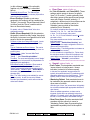
Exiting, Logging Off, or Changing
Operators
Shutting Down the MONITOR AFx
Director Software
To shut down the MONITOR AFx Director
software, click the X in the extreme upper-right
corner of the MONITOR AFx Director screen
(or open the File menu, and select Exit).
Tip: If you changed any desktop settings, and would
like to retain them, be sure to click the check-box
provided.
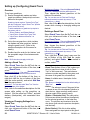
Then, select "Yes" on the confirmation screen.
If asked if you wish to shut down
communications as well (single-PC systems),
select Yes or No, as desired.
Attention: Shutting down communications while a
panel update is in progress is NOT recommended, as
this can leave panel database(s) in an unknown state.
Panel communications are required to:
• Update the monitoring window (live/real-time);
• Perform status & control tasks;
• Monitor guard-tours;
• Update panel(s) with changes.
Any active communications sessions (set to "stay
connected") will attempt to reconnect automatically, the
next time communications services are started.
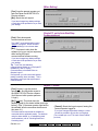
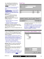
Logout or Lockout
To 'log' off, simply select Logout on the
toolbar (or open the File menu, and select
Logout).
Tip: If you changed any desktop settings, and would
like to retain them, be sure to click the check-box
provided.
Then, select Yes to 'logout', or No to put the
software in 'Lockout' mode. (See the 'Logout /
Lockout' screen descriptions for details.)
To protect against unauthorized access to the
MONITOR AFx Director software, it is always a good
idea to use the logout (or lockout) feature before
leaving your workstation. (For a related topic, see "The
Auto-Lockout Feature", previous.)
Changing Operators
Changing operators is simply a matter of one
operator logging out, and the second operator
logging in. (For details, see previous / above.)
10
MONITOR AFx™ Director V4.1 User's Guide
500-9041 v4.1
(When Exiting)
- [Yes]: Logs the present operator out,
and shuts down the MONITOR AFx
Director software.
- [No]: Aborts the exit request.
If you have changed any desktop settings,
a check-box will be provided to let you save
your settings.
(Single-PC, set to Auto-Start/Stop
Communications)
- [Yes]: Shuts down panel
communications services.
This is NOT recommended while a panel
update is in progress , as this can leave
panel database(s) in an unknown state.
- [No]: Continues to shut down the
software (or log you out) as requested,
while leaving the panel
communications software running.
If you have changed any desktop settings,
a check-box will be provided to let you save
your settings.
Tip: To turn the 'auto-start/stop
communications' feature on or off (single-PC
installations), refer to "Setting
Communications to AutoStart When an
Operator Logs In".
In all systems, you call connect with desired
panel(s) manually, when necessary. This is
described in each topic that requires panel
communications.
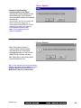
Logout / Lockout
- [Yes] (Logout): Logs the present
operator out, shutting down access to
the MONITOR AFx Director software.
(Until the next valid operator performs
a 'login'.)
- [No] (Lockout): This shuts down the
desktop except for the status toolbar (and login
button). (Tip: If the same operator logs back in,
the software will also remember what account
they were 'in'.)
The status toolbar requires that the software be
connected with the applicable panels. For details on
using the status toolbar, or on establishing panel
communications, refer to "Checking Status and
Controlling Items"
500-9041 v4.1
Welcome
Report
Control
- [Cancel]: Aborts the logout request, leaving the
present operator logged in.
If you have changed any desktop settings, a checkbox will be provided to let you save your settings.
(For a related topic, see "The Auto-Lockout Feature",
previous.)
Admin
Sys Config
Tech-Ref
11
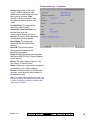
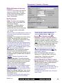
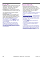
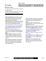
The Desktop
Welcome: This section contains a quick summary of
the desktop components, and how you can change the
look of your desktop.
For a detailed reference to the menu, toolbars, etc.,
refer to "Desktop Reference" (near the back of this
guide).
Your 'Window' to the System
The desktop is your interface to the MONITOR
AFx Director software, providing a familiar
Windows 'look and feel', with access to all
features and items assigned to you as a
MONITOR AFx Director operator.
The MONITOR AFx Director interface can be
set as desired by each individual operator.
This includes whether they prefer the MyTools
bar, or the Tree window, plus the sizing of the
desktop sections, and other settings.
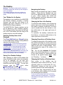
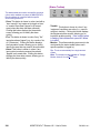
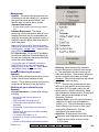
Selecting Desktop Items to be
Displayed
The [Tree], [MyTools] and [Events] buttons
on the toolbar allow viewing or hiding different
aspects of the desktop (try it!).
Your MyTools Bar: You can customize the look and
content of the MyTools bar to your own preferences.
For details, refer to "Customizing the MyTools Bar".
Account-Folders: For systems with single-account
licensing, only one account will appear in the tree. In
larger systems, [Account Folders] will be shown in the
tree for operators with multi-account permissions (or
that have the authority to edit account folders).
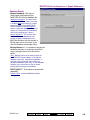
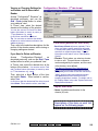
Saving Your Desktop Settings
After changing an aspect of the desktop (the
sizing, Forms/Grid mode, and/or which aspects
are to be displayed, you can save your
changes so the desktop appears in the same
format the next time you login. To save your
changes, open the View menu, select
Desktop Settings, and then Save.
Tip: You will also be asked if you want to save your
changes whenever you logout or exit from the software.
Navigating the Desktop
Many screens are divided into 'tabs' of related
settings. (Start with the 'Standard' tab, and
look in any additional tabs that are of interest
to you.)
Some screens also include the
familiar windows ‘scroll-bars’ whenever an item
is too large to fit on-screen.
Changing the Size of the Desktop
To resize the entire desktop, click and drag the
bottom right corner to the desired position. (If
the screen is presently 'maximized', you'll first
need to double-click the blue title-bar, or click
the middle button in the upper right corner of
the screen.)
To ‘maximize’ the desktop, double-click the
blue title-bar, or click the middle button in the
upper right corner of the screen.
Changing Proportions of Desktop Areas
To change the proportion of the desktop, move
the mouse to the edge of a screen area (such
as between the 'tree' and forms/grid area), and
watch for the cursor to change shape. Then,
click-and-drag the edge of the window to a
new location.
Tip: You can also maximize the form/grid
area, or the monitoring window (i.e., cause it to
fill the entire screen) by double-clicking the
title-bar for the specific window twice. (Also
see "Resetting...", to follow.)
Changing the Position of Desktop Items
Each portion of the desktop can be
repositioned, and/or viewed on its own. This is
especially useful on a multi-monitor PC (e.g.,
Windows98), allowing an item such as the
monitoring window to be viewed separately.
To relocate an item, 'drag-and-drop' the item
by its title-bar, while watching for the greyed
box indicating the new position.
To view an item 'full-screen' (such as the monitoring
window), double-click its title-bar twice. To access the
main desktop screen again, double-click the title-bar
once again.
12
MONITOR AFx™ Director V4.1 User's Guide
500-9041 v4.1
Resetting the Desktop
After moving and resizing areas of
the screen, you may wish to reset the
desktop to either your last saved
settings, or to the initial factory default
layout.
Last Saved Settings: Click Reset on
the toolbar (or open the View menu,
and select Desktop Settings, and
Reset).
Factory-Default Layout: Open the
View menu, and select Desktop
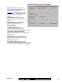
Settings, and Default).
Tip: If a window or portion of the desktop is
presently "maximized" (fills the entire
screen), you'll need to double-click its titlebar to access the menu or toolbar.
Note: If your desktop was accidentally
saved with the monitoring window
'undocked' and hidden behind the main desktop, follow
the preceding steps for "Factory Default Layout".
- The Menu: Provides access to some
miscellaneous features of the MONITOR AFx
Director software. Tip: The Tools menu
provides access to Wizards that simplify
setting up a new system, and/or enabling
communications with a panel.
- The Toolbar: Provides access to some
common tasks.
- The 'Tree' (optional): This is an expandable/
collapsible outline that allows selecting an
account, and provides access to most topics
including system configuration, management,
and status & control. Click [Tree] on the toolbar
- The Forms/Grid Area: This area shows
details on your present topic (as selected from
the tree or MyTools bar). This can be set for
either a forms view (typical / data entry), or
'grid' format (experienced persons / viewing
and sorting lists).
(Use the Form / Grid button on the toolbar to switch
views.)
- The Monitoring Window (optional): This
area shows recent events that have been
received (for a selected account).
Click [Events] on the toolbar to view or hide the
monitoring window.
to view or hide the 'tree'.
- The 'MyTools' Bar (optional): This is a
customizable list of tasks/items that can be
used as alternative to the 'tree'.
Click [MyTools] on the toolbar to view or hide the
MyTools list/bar.
You can customize the look and content of the
MyTools bar when you are logged in (View MyTools
Customize). For details, refer to "Customizing the
MyTools Bar".
500-9041 v4.1
Welcome
Report
Control
Multi-Account Systems: With multiple accounts, the
monitoring window shows the events for your present
account. (Select [Account Folders] in the tree, then
locate and double-click your desired account.)
To set the account to be monitored by the status
toolbar, click [Monitor] on the far-right end of the
toolbar.
- The Status Bar: This area (at the extreme
bottom of your desktop) shows whether or not
you are connected with a selected account
(i.e., associated panels), plus other
communications-related status messages.
Admin
Sys Config
Tech-Ref
13
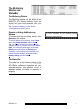
System Management Primer
System Management
The MONITOR AFx Director system provides
the flexibility to perform administration tasks
either locally, through a system keypad (with 2line LCD display), or through a MONITOR AFx
Director workstation (via direct-connect,
V3.3
modems, or IP ≥
). Persons with access to
a MONITOR AFx Director workstation will find
this the best place to start to perform the dayto-day management of the system.
Tip: Each operator will be able to see and use the
features and items as assigned to them through their
operator permissions.
Note: In a multi-PC system (client-server operation),
MONITOR AFx Director manages database changes
from multiple operators. If operators at two different
workstations try to make changes to the same item, the
last/second person to finish will be informed that
another operator has changed the item. (If this occurs,
click Refresh on the toolbar, scan the new settings, and
then perform any desired changes.)
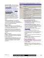
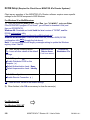
On a Typical Day
On typical day using the MONITOR AFx
Director software, will likely perform some (or
all) of these tasks:
For details, refer to "Users (Entrants / Panel
Users)", and/or "Authorities for
Users/Entrants".
• Set up a holiday (or the dates to switch
between standard-time and 'daylightsavings'. For details, refer to " Holidays and
Time-Change Dates".
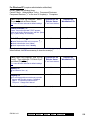
Locating Topics on the MONITOR
AFx Director Desktop
Using the MyTools List / Bar
• All tasks assigned to you can be accessed
through the MyTools list / bar.
• To open the MyTools bar, click [MyTools]
on the toolbar.
The look and content of the MyTools bar can be
customized to suit each specific operator. For details,
refer to "Customizing the MyTools Bar" (in the
reference topics).
These Topics are Available after
Clicking [Your Account] in the Tree:
(Multi-account systems: Select [Account Folders],
then double-click the account)
• "Control & Status" topics--including maps
and cameras ("Visual Director") if • Log into the software to gain access to your
available selections. For details, refer to
"Welcome to MONITOR AFx Director".
• Working with "Users" and their associated
"Authorities".
• Deal with any alarms indicated on the status
toolbar, or marked in red in the monitoring
window. For details, refer to "Monitoring
System Activity", "Maps and Video", and/or
"Checking Status and Controlling Items".
• Setting up a "Guard Tour", or using the
"Guard Tour Monitor".
• Run some reports on what occurred over the
past few days. For details, refer to "Timeand-Attendance Reporting", or "Reporting on
System & Personnel Activity".
• Check the status of a specific 'area' in the
facility, and/or control a door in an area.
For details, refer to "Maps and Video",
and/or "Checking Status & Controlling
Items".
• Enter (or change settings for) a visitor or new
employee (and/or associated authorities).
14
• "Schedule" and "Holiday"-related topics.
• "Account Information" including the mailing
address, event priorities and instructions,
and account-wide panel settings.
• System "Configuration" topics (for setting up
'Areas', and all devices (doors, monitored
sensors, etc.).
Multi-Panel Systems: With all "Control & Status" topics,
and "Configuration" topics (including "Areas",
panel/system settings, and readers/doors, monitored
sensors, etc.), you have a choice between having
topics shown in a single list, or on a panel-by-panel
basis. For details, refer to "Other Desktop Choices" in
the desktop reference.
MONITOR AFx™ Director V4.1 User's Guide
500-9041 v4.1
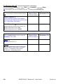
Other Portions of the Tree:
"What can be Done from Where"
• Management: This section includes
"Operators" and "Operator Permissions",
plus system/database management tasks.
For client-server systems, the list of
authorized clients is also accessed here.
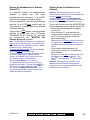
Adjusting the 'Closing' Time (Worklate) for an Active Schedule
The 'closing' time for a schedule can be
adjusted:
• By an authorized operator using the
MONITOR AFx Director software.
• Communications: This section contains
tasks regarding starting or stopping panel
communications, and viewing details on
previous sessions. Setting up
"Communications Pools" (part of the initial
system set up) is also included here.
• By an authorized user/entrant at a system
LCD keypad;
• By an authorized user/entrant at an 'arming
station' enhanced reader;
• Reports: This section allows running many
different types of reports pertaining to
personnel time-and-attendance, activity that
has occurred, and guard-tours that have
been run--in addition to printing or viewing
details on the items that have been set up in
the system.
• By pressing a 'worklate' button (inside the
controlled-access facility);
Work-late buttons are set up as custom input-point
types.
Arming / Disarming Areas
The arming and disarming of a system and/or
individual areas can be:
Selections that Require Panel
Communications:
For the following items, you must first start a
communications session with the panel(s).
(Multi-account systems: First click [Account Folders]
in the 'tree', and locate and double-click the account.
• Keeping the Monitoring window up-to-date
(for real-time monitoring);
• Performed by an authorized user/entrant at
an 'arming station' enhanced reader;
• Monitoring previous Guard-Tours (Guard
Tour Monitor under [Your Account] in the
tree);
• Updating panels with changes.
For details on setting up a panel communications
session, refer to "Panel Communications and Updates".
To set the account to be monitored by the status
toolbar, click [Monitor] on the right-hand end of the
toolbar.
Initial Set Up
For full details on the initial set up of a system,
refer to "Setting Up a New System
(Commissioning)".
See Also / Related Topics:
+ "New Installation? Try the Wizard!"
+ "Panel Connection Overview".
Welcome
Report
• Set to occur automatically at specific times
(Schedules and Area settings);
• Performed through the MONITOR AFx
Director software—by an authorized operator
(through "Control & Status" or a map-"Visual Director");
• Using the 'Status Toolbar' (Siren, Fire,
Alarm, Trouble);
• "Control & Status" topics (under [Your
Account] in the tree);
500-9041 v4.1
• Linked to an Event--such as when an exit
door closes (Area settings), or when an
authorized person is granted access
(Authority settings);
Control
• Performed locally through a system LCD
keypad by an authorized user (similarly, an
apartment/suite or facility can be armed and
disarmed through a suite-security keypad).
• Performed using a custom "arm/disarm
keyswitch" input-point.
Cardholder Administration
The administration of users/cardholders can be
done:
• Through this MONITOR AFx Director
Software (via modems or direct-connect);
• Locally through a system keypad (with 2-line
LCD display).
Admin
Sys Config
Tech-Ref
15
System Configuration
System/panel configuration can be done:
• By an authorized operator (with
"Configuration" permissions) through this
MONITOR AFx Director Software;
• Locally through an alarm system's keypad
module (by an authorized technician).
System configuration through the MONITOR AFx
Director software is supported through a direct-cableconnection or a dial-up (modem) connection to
associated panel(s).
All system configuration
requires knowledge of the 'Service PIN'.
Local user admin. (via keypad) is supported in all
systems, while local system configuration is
supported only in single panel systems set to
"Feature Set" 1, 2, 3, or 4. Exception: Keypad
programming is supported in all systems for any
'application' modules that require this due to custom
settings stored only at the module itself (HSC/printer
module, RF module, and Smart-PODs).
See Also (Related Topics):
+ Account Type and Feature-Set:
"Account-Wide Panel Settings".
+ Allowed Capacities: "Software Activation and
Licensing".
+ Maximum Capacities: "System Capacities".
+ Programming through an LCD Keypad:
Refer to your MONITOR AFx Commissioning
Reference Guide.
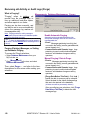
Avoiding False Alarms
No matter how full-featured, and reliable a
security system is, a number of steps must be
taken to absolutely minimize the likelihood of
false alarms occurring. These include:
1)
2)
3)
Ensuring the system's configuration
accurately reflects the requirements at the
site (regarding the working times and
movement of personnel during a typical
workweek, etc.).
Knowing how the police and fire departments
handle false alarms, and ensuring
appropriate procedures have been set up
with the monitoring station. For example,
identifying the types of alarms where an offsite security or maintenance person is to be
called either first, or instead of the police.
Ensuring all authorized persons know "where
they can go and when", and have received
appropriate training on the system. For
example, how to disarm the area, adjust the
'work late' time, and perform other basic
tasks through an LCD keypad.
Tip: To greatly minimize false alarms pertaining to
personnel entering an armed area, the system will:
• Allow persons to enter only if they have the authority
to disarm the applicable area, or:
• Disarm the area automatically when the person is
granted entry (optional / if set for this).
16
MONITOR AFx™ Director V4.1 User's Guide
500-9041 v4.1
Monitoring
Activity, and
Running Reports
500-9041 v4.1
Welcome
Report
Control
Admin
Sys Config
Tech-Ref
17
Monitoring System Activity
Alarm and Activity Monitoring
Alarm and Activity Monitoring through
the MONITOR AFx Director System
When the MONITOR AFx Director system is
connected with specific panel(s), all events
and alarms are transmitted for display in the
monitoring window, allowing the tracking of
guard tours, and to allow for various types of
report generation.
Dial up panels with dedicated external modems (one
panel per modem) can be set to automatically dial-in to
the MONITOR AFx Director system to transmit alarms
or blocks of activity messages. In other configurations,
the alarms and events are transmitted when a
connection is made with the specific panel(s)—either
manually, or at scheduled times.
Real-time monitoring (immediate reporting) through
MONITOR AFx Director requires that the software
remain connected with the specific panel(s).
Multi-Account Systems: The monitoring window is
activated for a specific account when you double-click
the account (under [Account Folders] in the tree).
For details on activating a panel connection, and the
"Stay Connected" setting, refer to "Panel
Communications and Updates".
To set a dial-up panel to automatically transfer alarms
or blocks of activity messages, refer to the configuration
topic: "Monitoring, Paging, & Remote Mgt. Settings".
Sites Monitored through a CentralMonitoring Station
Sites can additionally be monitored through a
dedicated central-monitoring facility. In this
case, you can set whether only the 'alarms' or
all activity is to be transmitted—on an area-byarea basis. As well, individual sensors (input
points) and monitored panel conditions
(equipment / pseudo-points) can be set as to
the area arming states for which each
condition will be reported to the central-station
(On, Stay, and/or Off).
Monitoring Station Connection: Central monitoring is
supported through:
• The panel's built-in dialler ('Bell 103', 300 baud
modem), and/or;
• An "IP" connection (LAN/WAN--if ≥ v3.3 panel &
software), or;
• A high-security Mark 7 / DVACS connection (Canada).
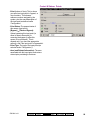
18
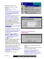
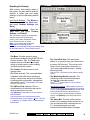
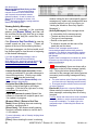
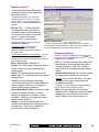
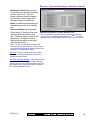
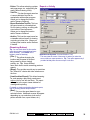
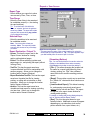
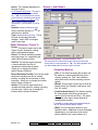
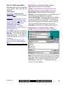
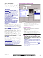
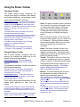
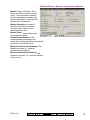
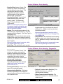
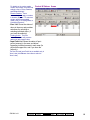
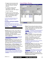
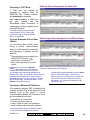
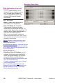
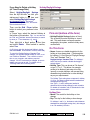
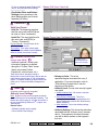
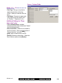
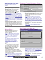
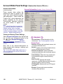
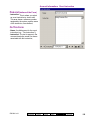
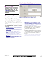
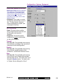
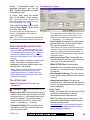
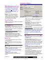
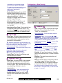
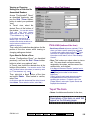
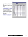
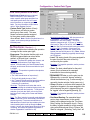
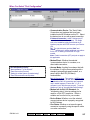
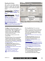
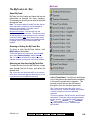
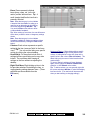
The System Monitoring Window
The monitoring window shows the alarms and
activity messages for the account selected in
the tree (double-click an account to select).
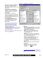
Tip: Alarms typically appear with a red box next to
them (click the red box to open a "Notes" window).
The top of the monitoring window shows either
the newest messages, or all 'unresolved' (and
higher priority) events first.
As well, the
window can be set to show all activity, or only
specific types of events (saved per operator).
For details, refer to "Limiting the Window to Show Only
Specific Messages", to follow/below).
Tip: You can customize how alarms and events will be
displayed, and assign a sound to specific events if
desired. For details, refer to the configuration topic:
"Customizing How Events are Displayed"
The scroll-bar on the right allows viewing
events that have been pushed off the bottom
of the screen.
Note: The 'heartbeat' icon in the bottom-right corner of
the screen will change to a red until you select
[Return to Real-Time Mode]. (While scrolling, new
messages will not appear in the window.)
Messages are transmitted the MONITOR AFx
Director software:
• When you connect with an associated panel
(such as when updating a panel with
changes, or to check the status of a device);
• When a (dial-up) panel calls in to transmit
messages.
The Archive and Purge features allow keeping the
activity log to a more manageable size.
See: "Exporting or Importing Activity or Audit Logs",
and "Removing old Activity or Audit Logs".
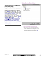
The Status Bar (bottom of the form)
The status area at the extreme bottom of the
screen shows whether or not the software is
presently connected with a specific panel,
and/or if an update is presently in progress.
Activity messages are held at the specific panel
whenever it is being updated/synchronized with the
software (the messages will be available for
transmission after the update is finished).
MONITOR AFx™ Director V4.1 User's Guide
500-9041 v4.1
Also See: (Topics Pertaining to Central Monitoring):
• "Primary Reporting" selections under "Monitoring,
Paging, & Remote Mgt. Settings".
• "Reporting" setting under "Areas and Related
Settings".
• "Inputs—Monitored Sensors", and the "Transmit"
selections under "Inputs—Pre-Defined Point Types",
"Inputs—Custom Point Types", and "Equipment
Settings (Pseudo/Internal Inputs)".
'Activating' and Using the
Monitoring Window
[Communications] in the 'tree', and
select Pending/OnLine.
4) Click the [+] at the bottom of the form, or
right-click the form, and select Add New
from the pop-up menu. Then, select the
desired panel(s) (double-click to select),
and set "Action" to "Normal", and
"Frequency" to "Stay Connected" ().
(Click OK when finished.)
5) Check that the connection is made, and
watch for the panel updates to occur.
Selecting an Account (Multi-Account
Systems)
Click [Account Folders] in the 'tree', and
locate and double-click the desired account.
The monitoring window will show the
messages for the account that have been
received.
(Click the 'Panel Group', and look for the status on
the right side of the screen.)
Note: Alarm and activity messages are transferred
after the panel updates (look for a connection state of
'Connected' and 'Idle State'.)
Also See (Related Topics):
+ "New Installation? Try the Wizard!"
+ "Panel Communications and Updates"
+ "Panel Connection Overview"
Tip: Your selected account will remain 'open' (e.g., for
the event monitoring window) until you select [Account
Folders] or [Management] in the 'tree'. Selecting an
account is typically not required for a single-account
system (single account license and/or operators without
authority to edit account folders).
Opening and Adjusting the Monitoring
Window
If the monitoring window is not visible, click
[Events] on the toolbar.
Connecting to the Associated Panel(s),
An Overview:
For the latest up-to-date messages, you must
be connected with the associated panel(s).
(Otherwise, you will see only messages that
were received previously).
1) See if you're already connected by
checking the status bar at the bottom of
the monitoring window.
Multi-account systems: Ensure your
desired account is selected
(click [Account Folders] in the tree, and
then double-click the specific account).
2) If not connected, check to ensure the
communication software is running on
the specific PCs (check the Windows
task-bar for an LCD/Telephone symbol).
Start up the software if necessary.
(From the Start menu, select: Programs,
MONITOR AFx Director V4, and
MONITOR AFx Director-Communications.)
3) Select Communications from your
MyTools bar, or click
500-9041 v4.1
Welcome
Report
Control
If nothing seems to happen, click [Reset] on the toolbar
(and click [Events] again if necessary). Note: If your
desktop was accidentally saved with the monitoring
window 'undocked' and hidden behind the main
desktop, open the View menu, select Desktop
Settings, and then Default.
To adjust the size of the monitoring window,
position the mouse cursor at the top of the
window, watching for the cursor to change
shape. Then, click-and-drag the top of the
window to the desired new position.
To maximize the size of the monitoring
window, double-click its title-bar twice.
To restore the MONITOR AFx Director desktop at any
time, simply click Reset on the toolbar.
(If the monitoring window is presently maximized,
double-click its title-bar first.)
Tip: With multi-monitor support (e.g., Windows 98),
you can place the monitoring window in a separate
screen: Double-click the monitoring window title-bar,
and then drag it onto the second screen.
Reminders: The monitoring window is updated only
when you are connected with the specific panel(s).
Muti-Account Systems: The monitoring window is
active only while you have a specific account 'open' in
the tree (select [Account Folders], and then doubleAdmin
Sys Config
Tech-Ref
19
click the account).
Monitoring Window Blank During or After
a Panel Update: The monitoring window
may take a minute or two to refresh at the
end of a panel communications session
(please be patient). As well, to ensure the
desired type of messages are shown, click
[Filter], and verify the filtering / sorting selections
(details in a following topic).
Viewing Activity Messages
To view older messages in the monitoring
window, click [Browse Offline], and then use
the scroll-bar on the right (click the up or down
arrows, or slowly drag the control bar in the
middle).
Click [Return to Real-Time Mode] to view the
newest events as they occur. (These will
appear at the top of the monitoring window.)
For longer messages, use the horizontal scrollbar (bottom-right) to view the end or beginning
of the desired message(s).
If you wish to print activity messages, refer to
"Reporting on System & Personnel Activity.
When alarms occur, ensure they are not ignored. Be
sure to dispatch someone to deal with any
conditions that require attention.
- Vertical Scroll-Bar (right-hand side): Allows
scrolling up and down to view older messages in
the monitoring window. (Click the up or down
arrow, or slowly drag the control bar.)
Note: You must first select [Browse Offline] at the
bottom (details to follow/below).
- Horizontal Scroll-Bar (bottom-right): Allows
scrolling to the left and right to view longer
messages. (Click the left or right arrow, or drag
and release the control bar.)
- Status Bar (bottom of screen): Shows if the
software is connected with a specific panel, and
if an update is in progress.
- [Browse Offline] / [Return to Real-Time
Mode]: Allows activating the event monitoring
window vs. scrolling inside it.
- [Show Photo]: This allows manually opening
the photo-verification window to view the last 1,
4, or 9 entrants.
window, limiting the list to show specific types of
messages only, and/or only messages that have
not been 'resolved' (see last 2 items below, plus
"Limiting the Window to Show Only Specific
Messages".);
- (Activity Messages): Each message shows:
•
•
•
•
•
A coloured bar for the message priority;
The date and time the event occurred;
The type of event/message;
Details on the specific event.
A reference number and the name of the
panel that sent the alarm;
"Session Code" messages pertain to panel
communications/update sessions being started or
completed. (For details on communications sessions
that have occurred, refer to "Panel Communications
and Updates".
"System Check" messages are for internal use, and/or
of interest only when working with your technical
support representative.
------------------------(coloured box): Alarms are shown with a
box/button on the left of the message (typically
red). Clicking the button allows entering a
comment for the message (and viewing previous
comments), and/or setting messages as being
'resolved';
:
The event has been set as 'Resolved' (dealt with).
(you'll see this only if displaying resolved events);
?: A comment has been entered, but the event was
not set as 'Resolved'.
- Resolve All (Right-click, or from the Edit Menu):
Allows entering a comment for all displayed
alarm messages, and setting them all as being
'resolved'.
TechTip: Alarms and events can be set as 'resolvable'
or not (i.e., whether or not the comment/resolution
screen will be available). For details, refer to the
configuration topic: "Customizing How Events are
Displayed".
For more information, refer to "Visually Verifying Users
(Photo-Verification)".
- [Filter]: Allows resorting the event / monitoring
20
MONITOR AFx™ Director V4.1 User's Guide
500-9041 v4.1
When you Click [Filter]
Limiting the Window to
Show Only Specific
Messages (Sorting and
Filtering)
The monitoring window can be set to
show:
•
•
•
•
All event messages for an account;
Only 'unresolved' events;
Events of a specific priority range;
Events pertaining to a specific door,
area, person, etc.
Tip: These selections are saved separately
for each operator.
You can also set the 'sort-order' for
messages. To determine the present
sort-order, and whether or not the list
is limited to specific events, look for
references in the title-bar of the
monitoring window.
To set the window to show only
specific types of messages, click
[Filter] at the bottom, and make your
selections from the pop-up window.
Tip: You can select [Clear] to remove your
present 'filters', and return to showing all
messages for the present account.
- Sort Order By: This allows listing messages in
order by date/time only, or showing 'unresolved'
(and higher priority) events first.
- Filter on Resolution: This lets you have the list
include events depending on whether or not
they have been 'resolved' (i.e., dealt-with).
All: This shows all events--including ones not
associated with the comment/resolution feature (i.e.,
not set as 'resolvable').
- Filter on Priority: This allows limiting the
window to show only events of a desired priority
value (or range).
- Filter on Custom Filter: This allows limiting the
window to show only events of a desired
'custom-filter' value (or range).
Also See: To assign priorities, 'Custom Filter' values,
and other parameters, refer to the configuration topic:
"Customizing How Events are Displayed".
- [Clear]: Removes all filters--i.e., returns to the
factory settings (and closes the 'filter' window).
[More] / [Hide]
- Filter on Item: For events pertaining to a
specific person or door, etc., select the desired
item here.
500-9041 v4.1
Welcome
Report
Control
Admin
Sys Config
Tech-Ref
21
Dealing with Alarms
(Comment / Resolve)
Alarm Notes / Comments
While responding to alarms, you can
enter a note for each alarm
describing what caused it, what was
done to correct the problem, etc. You
can also set the alarm as 'resolved' (
), or 'Keep Unresolved' ( ? ).
Tip: You can set the monitoring window to
show only alarms that either have, or have
not been 'resolved' (for details, refer to the
preceding topic).
Entering or Viewing Alarm
Comments
To enter (or view) an acknowledgement note
for an alarm, click the red area beside the
alarm. Then, enter the desired message and
select [Resolved], or [Keep Unresolved].
You can enter two or three short notes (saved
individually by clicking OK) or a single larger one for
each alarm as desired.
- Alarm Detail: Details on the alarm, and when it
occurred.
- Comments: Previously entered comments, plus
an area to enter new one(s). Tip: There is
enough space for two or three short notes
(saved individually by clicking OK), or a single
larger note.
- [Resolved]: Sets the event as having been
dealt-with. If the alarm/monitoring window is not
set to show only unresolved alarms, you'll see
the message with a "" beside it.
- [Keep Unresolved]: This saves your comment,
and displays the event with a "?" beside it to
indicate further resolution is needed.
- [Cancel]: This aborts any changes you entered
in the 'Alarm Acknowledge' screen.
TechTip:
Alarms and events can be set as
'resolvable' or not (i.e., whether or not the
comment/resolution screen will be available). As
well, if 'instructions' have been set up for the specific
type of alarm, they will appear here. For details, refer
to the configuration topics:
+ "Alarm/Event Instructions", and
+ "Customizing How Events are Displayed".
22
MONITOR AFx™ Director V4.1 User's Guide
500-9041 v4.1
When Messages Cannot be
Transmitted to the MONITOR AFx
Director Software
If the MONITOR AFx Director software is not
connected with the specific panel, messages
are not transmitted, and each individual panel
will retain up to 65,536 of the latest events that
occurred.
Exception: Remote (dial-up) panels with their own
dedicated external modem (i.e., one panel per modem)
can be set to automatically 'dial-in' and transmit
messages to the MONITOR AFx Director software.
These messages will appear in the monitoring window
when you access the associated account.)
For details, refer to "Monitoring, Paging, & Remote Mgt.
Settings".
Note: Panel connections require that the
communications software be running on the specific
PC.
The event-log capacity of each panel depends on the
panel's "Feature Set" selection.
For details, refer to "Account-Wide Panel Settings".
500-9041 v4.1
Welcome
Report
Control
Admin
Sys Config
Tech-Ref
23
Visually Verifying Users (Photo-Verification)
Photo-Verification
View Photo Verification Show
(or when a person enters at the specific door)
Introduction
Each operator can set a door to have
the stored photo for entrants
displayed whenever they gain access
at that door. The last 1, 4, or 9
entrant's photos can be displayed.
The photo can then be used to verify
each entrant's identity. This can be
done locally--such as by an attendant
in a reception area, or remotely through a
camera on a map.
This feature is configurable separately for each
operator (as described in a following section/below).
This pertains to the photo associated with
each card/person in the "Users" screen.
For details, see "The Photo-Badging
Option".
This screen shows the last 1, 4, or 9 persons
who gained access at a door that you selected
for photo-verification.
The photo window is cleared each time you change
settings for this feature, and when you select anything
outside of the specific account.
Using This Feature
The photo window opens automatically
whenever a person gains access at the
specific door.
Multi-Account Systems: This works only while the
specific account is selected. (Click [Account Folders]
in the 'tree', and double-click the specific account.)
You can also open the photo window manually
by clicking [Show Photo] at the bottom of the
monitoring window.
Window Empty: The photo window is cleared each
time settings are changed for this feature, and when
you select anything outside of the specific account.
Now, visually compare the displayed photo
with the person to verify their identity.
Setting the Window Position
To reposition the photo window, simply clickand-drag its title-bar to the new location.
Closing the Photo Window
To close the photo window at any time, click
the [X] in the upper-right corner.
24
MONITOR AFx™ Director V4.1 User's Guide
500-9041 v4.1
View Photo Verification Customize
Setting up This Feature
Each operator can set the photoverification feature to suit their
preferences.
Authorities: This feature is available to all
operators.
Steps:
1)
Multi-Account Systems: Ensure
you are 'in' the desired account.
(Click [Account Folders] in the
'tree', and double-click the specific
account.)
2)
From the View menu, select
Photo Verification
Customize.
3)
Refer to the selection-descriptions
for this screen while making your selections.
Photo Verification
- Disable: Photo verification will be turned off
while you are logged in (i.e., the present
operator);
- Enable for Current Account: Photo
verification will be turned on while you are
logged in (i.e., the present operator);
Doors
This area shows all main panels and doors
associated with your account, and allows
selecting a door to be associated with photoverification.
Photo View
This allows selecting the number of user photos
that will be visible at one time (1, 4, or 9);
Photo Display Duration
- Always Visible: The photo-verification window
will remain open for as long as you remain 'in'
the specific account;
- Duration Time (min): If you do not select
"Always Visible", this allows selecting how long
the photo window will remain open each time it
is activated (1-99 minutes).
Note: You can also close the photo window manually,
by clicking the [X] in the upper-right corner.
500-9041 v4.1
Welcome
Report
Control
Admin
Sys Config
Tech-Ref
25
Time-and-Attendance Reporting
Time and Attendance Reports
Cardholder time and attendance reporting
allows generating reports pertaining to the
presence (roll-call), tardiness, number of hours
at work, etc. for users pertaining to a specific
account.
These reports are extrapolated from entry and
exit (access granted) messages in the activity
log, and compared against a selected
"attendance-period" that defines when the
users are supposed to be inside the facility.
TechTip: Reports pertaining to past events are based
on the present event list, plus any archived data that
has been re-imported using the archive feature.
See: "Exporting or Importing Activity or Audit Logs".
For accurate attendance reporting:
• The site (account) must have a ‘Required
Attendance Zone’ defined by setting the "Area" as
"Outside" for all readers used to exit from this
zone.
For details, refer to "Reader 1 & 2 Settings for a
Door".
• Persons must use their access card / token
EVERY time they enter and exit the facility.
Required-Attendance Time Periods
To allow time & attendance reporting, each site
(account) must have required attendance time
periods set up that specify the days and blocks
of time that employees are supposed to be
inside the facility.
For details, refer to "Required-Attendance Time
Periods".
Running a Time and Attendance Report
1)
2)
Tip: This option appears only if you didn't already
have an account 'open' in the tree.
3)
For details, refer to "Exporting or Importing Activity or
Audit Logs", and "Removing old Activity or Audit Logs".
5)
Select the desired type of report (see the
"Report Type" description for details).
Select the "Attendance period" that specifies
when persons are supposed to be in the
facility.
Notes: An attendance period is not required for
"Arrival / Departure", "Roll-Call" or "In/Out Status"
reports. If a suitable attendance-period is not
listed, refer to "Required-Attendance Time
Periods" to set one up now.
6)
Areas set for Antipassback Checking: The "APB AutoReset" feature is generally not recommended where
Time & Attendance reporting functions will be used.
For details on the 'Antipassback' feature, and the "APB
Auto-Reset" selection, refer to the "Antipassback"
settings in the "Area" configuration topic.
Select the range of dates to be covered by
the report ("From" and "To"), and the time to
be used as the "Start of Day".
Tip: See the item-descriptions for more info.
4)
Attendance reports can take a full minute or longer to
appear--depending on the number of cards at the site,
and the number of activity messages being scanned.
For better performance, be sure to select the smallest
date-range that meets your requirements. Also, you
can keep the activity log to a suitable size via regular
use of the Archive and/or Purge features.
Select Time and Attendance Report from
your MyTools bar, or click [Reports] in the
'tree', and select Time and Attendance.
Multi-Account Systems: Select the desired
account near the centre of the screen.
7)
8)
To limit the report to a specific authority,
user, etc., click [Search For], and select the
desired criteria.
Tip: To clear a selection, select it and use your
Backspace or Delete key.
Tip: You can scroll within the form to view
additional items if necessary.
Select a report 'destination' (i.e., whether it is
to be viewed, printed, or saved as a file).
If you select "Archive" or a type of "File",
click [File...], set the location and filename
as desired, and click Save.
Click [Run], and respond to any additional
screen(s) that appear (details to follow).
For details on viewing and printing displayed reports,
refer to "Working with the Report Viewer".
26
MONITOR AFx™ Director V4.1 User's Guide
500-9041 v4.1
If Printing an Attendance Report
To print a report without viewing it first: Select
the type of report and other criteria as usual,
and select Printer as the destination. Then,
select Run, and click OK when the 'Print'
screen appears. Tip: To select a different
printer click Printer, and make your selection
from the 'Print Setup' screen that appears.
To view a report before printing: Select the
type of report and other criteria as usual,
and select 'Screen' as the destination.
Then, click Run.
For details on viewing and printing the
displayed report, refer to "Working with the
Report Viewer".
A sample screen and selectiondescriptions appear on the following
pages.
If Exporting an Attendance Report as a
File (Archive/TextFile/Report Emulation
File)
Select the type of report and other criteria as
usual, and the desired file-type as the
'destination'. Then, click [File...]. In the next
screen, set the location and filename as
desired, and click Save when finished. Then
click Run.
Viewing/Printing a Previously Saved
Attendance Report-Archive
Select Time and Attendance Report from
your MyTools bar, or click [Reports] in the
'tree', and select Time and Attendance.
Then, click [Load archived report] at the
bottom of the form (scroll down if necessary).
Multi-Account Systems: You do not have to select an
account since that was done when the report was
archived.
In the next screen, locate and select the
desired archived report (.raf), and click Open
(or simply double-click the file).
For details on viewing and printing displayed reports,
refer to "Working with the Report Viewer".
500-9041 v4.1
Welcome
Report
Control
Admin
Sys Config
Tech-Ref
27
Report Period
- From and To (date): The beginning and end
date from the event log to be checked for
cardholder activity. (Change the values
manually, or click the arrow to access a pop-up
calendar.)
Note: Roll-call and In/Out status reports use the
previous 48 hours as a date/time range (instead of the
"From" and "To" settings).
- Start of Day: This setting allows shifts that
span midnight to be handled properly. Leave
this as 12:00 AM for all work shifts that begin
and end on the same day. For a shift that spans
midnight, select a time at some midpoint
between the end of one shift and the beginning
of the next one (perhaps 1:00 PM).
Report Type
- Absentee: Persons absent during one or more
time intervals of the required-attendance period.
- Arrival/Departure: The time of the first arrival
and last departure for all persons present on
each day covered by the report.
- Early Departure: Persons who left before the
end of one or more time intervals of the
required-attendance period.
Persons who leave early at the end of the day, but
later return after-hours (on the same workday) are not
treated as an early departure.
- Late Arrival: Persons who arrived after the
beginning of one or more time intervals of the
required-attendance period.
- Totalization: The duration each person spent
inside the facility on each day during the
required-attendance times.
- Roll Call: All persons presently tracked as
being inside the facility's required-attendance
zone (see note);
- In/Out Status: A list of all users, showing
whether they are presently tracked as being
inside or outside of the facility's requiredattendance zone (see note).
Note: For details on setting up a ‘Required
Attendance Zone’, refer to "Reader 1 & 2 Settings for
a Door".
28
MONITOR AFx™ Director V4.1 User's Guide
500-9041 v4.1
Attendance Period
A time period (previously-defined) that
specifies when persons are required to
be inside the facility.
Reports Time and Attendance
An attendance period is not required for
"Arrival/Departure", "Roll-Call" or "In/Out
Status" reports. To set up an attendance
period, refer to "Required-Attendance Time
Periods".
[Search For] / [Clear Search]
- This displays or closes the centre of
the screen, which contains selections
for 'fine-tuning' the report to a specific
person, or users with a certain
authority-profile or other criteria.
(Multi-Account Systems: Account Selection 'Tree')
To clear a selection, select it and use your
- This area (near the centre of the screen) is where you select the
Backspace or Delete key.
account that your report pertains to. Tip: This option appears only if
Custom User Field: This pertains to
you didn't already have an account 'open' in the tree.
(optional) custom user information
categories that can appear at the bottom of
the 'User' screen.
(Remaining Buttons)
Past Employees Deleted from the System: You can
(You may need to scroll within the form and/or resize
type a name rather than selecting it. This allows
the window to view additional items. Click Reset on the
running a report on persons (and/or items) that have
toolbar to reset the desktop.)
been recently deleted.
Report Destination / Output To
- Screen: This has the report sent to the 'Report
Viewer' window for viewing and/or printing
desired pages;
- Printer: This allows selecting a printer and
page-range, etc., and printing the report (without
viewing it first);
- TextFile: This has the report saved as a
'comma-delimited' text file for manipulation with
another program. Allows you to change the
location and/or filename if desired.
- Report Emulation TextFile: This has the report
saved as a formatted text file for viewing,
printing, or editing with a text editor or word
processor. Allows you to change the location
and/or filename if desired.
- Archive: This has the report saved as a
viewable archived report for viewing or printing
at a later time. Allows you to change the
location and/or filename if desired.
500-9041 v4.1
Welcome
Report
Control
- [File...]: This allows changing the location and
file-name for a report being saved for future
viewing, printing, etc. Tip: Use a different
name each time to avoid overwriting previous
reports.
- [Load Archived Report]: This allows browsing
for, and opening a previously saved reportarchive (not for use with text files). The report
will appear in the report-viewer window for
viewing and/or printing.
For details on viewing and printing displayed reports,
refer to "Working with the Report Viewer".
- [Run]: This runs the report based on your
selected criteria. Additional screens will appear
depending on your selections (such as the
printer selection form, report viewer, etc.).
Admin
Sys Config
Tech-Ref
29
Required-Attendance Time-Periods
Attendance Periods
Attendance periods are weekly blocks of time
that allow time & attendance reports to 'know'
when users are supposed to be in the facility.
Schedules for cardholder access must span a larger
period of time than the applicable attendance period--to
let people enter the facility before their shift begins, and
leave after it ends.
Adding (Setting up) an Attendance
Period
Select Time & Attendance Schedule from
your MyTools bar, or click [Reports] in the
'tree', open the Time and Attendance branch,
and select Attendance Period.
Multi-Account Systems: Select the desired account
near the centre of the screen. Tip: This option
appears only if you didn't already have an account
'open' in the tree.
Now, click [+] at the bottom of the form, or
right-click the form, and select Add New from
the pop-up menu.
Alternative: You can also select a blank/grey item from
the list (bottom of the form). Note: Grid view does not
apply to this screen.
Viewing or Changing Settings for a
Required-Attendance Period
Select Time & Attendance Schedule from
your MyTools bar, or click [Reports] in the
'tree', open the Time and Attendance branch,
and select Attendance Period.
Multi-Account Systems: Select the desired account
near the centre of the screen.
Now, choose the desired attendance period
from the list (bottom of the form), and refer to
the selection-descriptions for this screen while
viewing and/or changing settings as desired.
Deleting an Attendance Period
Select Time & Attendance Schedule from
your MyTools bar, or click [Reports] in the
'tree', open the Time and Attendance branch,
and select Attendance Period.
Multi-Account Systems: Select the desired account
near the centre of the screen.
Now, choose the desired attendance period
from the list (bottom of the form). Then, rightclick a blank area near the bottom, and select
Delete. When asked to confirm, choose Yes.
The attendance period is shown graphically,
for Sunday through Saturday. Add a new timeinterval by right-clicking a specific day, and
selecting Create New Time Interval.
Then, drag the interval and/or its end-points to
the desired location. Tip: Copying, pasting,
and deleting is also allowed when you rightclick a specific time-interval.
Repeat this process until the desired times are
set up for all days in the attendance period.
(You can use up to 6 unique time intervals
throughout each schedule.)
Now refer to the selection-descriptions for this
screen for additional information.
Tip: You can copy all settings for an attendance
st
period, and paste them into another one: In the 1 one,
right-click near the bottom of the form, and select Copy.
Then, select a blank/new attendance period from the
list, right-click near the bottom of the form, and select
Paste. After 'pasting', change the name and any
settings as desired. Note: 'Copy' and 'Paste' are also
available from the Edit menu.
30
MONITOR AFx™ Director V4.1 User's Guide
500-9041 v4.1
Reports Time and Attendance Attendance Period
- Attendance Period (bottom of form):
This is where you select an attendance
period to view or edit. This area
shows a reference number assigned
by the system, and the name of the
attendance period, once defined;
- Name: A suitable name/description for
the attendance period, or its intended
use;
- Days of the Week (with Associated
Time-Intervals): The days of the week
showing the time intervals for each
day. (To add an interval, right-click the
specific day. To adjust an interval,
drag the interval and/or its end-points
to the desired position.)
(Multi-Account Systems: Account Selection 'Tree')
- This area (near the centre of the screen) is where you select the
account that your attendance-period pertains to. Tip: This option
appears only if you didn't already have an account 'open' in the tree.
Tips: You can copy and paste (or delete) time
intervals using the right-click menu. Up to 6 unique
time-intervals can be used as desired throughout the
weekdays in each attendance period.
Split Shift: Be sure to include an interval for after a
meal break—assuming the break is not part of the
'required attendance' times.
Work Shift that Spans Midnight: In this case, each day
will need two intervals for the times before and after
midnight, plus any other required intervals (such as for
after a meal break—assuming the break is not part of
the 'required attendance' times).
500-9041 v4.1
Welcome
Report
Control
Admin
Sys Config
Tech-Ref
31
Reporting on System & Personnel Activity
Activity Reports
Activity reporting allows viewing or printing a
listing of various types of events that have
occurred for a specific account. A date/time
range can be specified, and the report can also
be limited to a specific area, device, person,
etc.
TechTip: Reports pertaining to past events are based
on the present event list, plus any archived data that
has been re-imported using the archive feature.
See: "Exporting or Importing Activity or Audit Logs".
As well, activity reports can be viewed and/or
printed right away, saved for future reference,
or exported for manipulation with another
program.
For better performance, activity reports cover only the
latest 5000 messages in the activity log. For even
faster execution, keep the activity log to a suitable size
via regular use of the Archive and/or Purge features.
See: "Exporting or Importing Activity or Audit Logs",
and "Removing old Activity or Audit Logs".
Running an Activity Report
1) Select Activity Report from your MyTools
bar, or click [Reports] in the 'tree', and select
Activity.
2) Multi-Account Systems: Select the desired
account near the centre of the screen.
Tip: This option appears only if you didn't already
have an account 'open' in the tree.
3) Select the date/time range to be covered by
the report (under "From" and "To").
Tip: See the item-descriptions if you need help.
4) Select the types of events to be included in
the report (you must select at least one).
5) To limit the report to a specific person, area,
door, etc., click [Search For], and select the
desired criteria.
To clear an individual selection, select it and use
your Backspace or Delete key. To reset/clear all
selections, scroll down and click [Reset].
Tip: You can scroll within the form to view
additional items if necessary.
6) Select a report 'destination' (i.e., whether it is
to be viewed, printed, or saved as a file).
If you select "Archive" or a type of "File", click
[File...], set the location and filename as
desired, and click Save.
7) Click [Run], and respond to any additional
screen(s) that appear (details to follow).
For details on viewing and printing displayed reports,
refer to "Working with the Report Viewer".
32
MONITOR AFx™ Director V4.1 User's Guide
500-9041 v4.1
If Printing an Activity Report
To print a report without viewing it first: Select
the type of report and other criteria as usual,
and select Printer as the destination. Then,
select Run, and click OK when the 'Print'
screen appears. Tip: To select a different
printer click Printer, and make your selection
from the 'Print Setup' screen that appears.
To view a report before printing: Select the
type of report and other criteria as usual,
and select 'Screen' as the destination.
Then, click Run.
For details on viewing and printing the
displayed report, refer to "Working with the
Report Viewer".
If Exporting an Activity Report as a File
(Archive/TextFile/Report Emulation File)
Select the type of report and other criteria as
usual, and the desired file-type as the
'destination'. Then, click [File...]. In the next
screen, set the location and filename as
desired, and click Save when finished. Then
click Run.
Viewing/Printing a Previously Saved
Activity Report-Archive
Select Activity Report from your MyTools bar,
or click [Reports] in the 'tree', and select
Activity. Then, click [Load archived report]
at the bottom of the form (scroll down if
necessary).
Multi-Account Systems: You do not have to select an
account since that was done when the report was
archived.
In the next screen, locate and select the
desired archived report (.raf), and click Open
(or simply double-click the file).
For details on viewing and printing displayed reports,
refer to "Working with the Report Viewer".
A sample screen and selectiondescriptions appear on the following
pages.
500-9041 v4.1
Welcome
Report
Control
Admin
Sys Config
Tech-Ref
33
Event Period
- From and To (date and time): The beginning
and end date from the event log to be checked
for cardholder activity.
Tip: You can change the dates manually, or click the
arrow to access a pop-up calendar. To set the times,
click within the 'hours' or 'minutes', and use the
up/down arrow keys.
Event Type
- The various types of messages that can be
included in the report (select the ones that you
want included).
Note: You must select at least one event-type.
"Toggle All" allows selecting or de-selecting all eventtypes.
[Search For] / [Clear Search]
- This displays or closes the centre of the screen,
which contains selections for 'fine-tuning' the
report to a specific person, area, door, etc.
Custom User Field: This pertains to (optional) custom
user information categories that can appear at the
bottom of the 'User' screen.
Show on Resolution: This lets you have the list include
events depending on whether or not they have been
'resolved' (i.e., dealt-with). "All": This shows all
events--including ones not associated with the
comment/resolution feature.
For details on resolving events, refer to "Dealing with
Alarms (Comment / Resolve)" in the section on
monitoring activity (previous).
Show on Priority: This allows limiting the window to
show only events of a desired priority value (or range).
Show on Custom Filter: This allows limiting the
window to show only events of a desired 'custom-filter'
value (or range).
Also See: To assign priorities or 'Custom Filter'
values, refer to the configuration topic: "Customizing
How Events are Displayed".
Tip: To clear an individual selection, select it and use
your Backspace or Delete key. To reset/clear all
selections, click the [Reset] button at the bottom of
the form (scroll down if this button is not visible).
Past Employees Deleted from the System: You can
type a name rather than selecting it. This allows
running a report on persons (and/or items) that have
been recently deleted.
Report Destination / Output To
- Screen: This has the report sent to the 'Report
Viewer' window for viewing and/or printing
desired pages;
34
MONITOR AFx™ Director V4.1 User's Guide
500-9041 v4.1
- Printer: This allows selecting a printer
and page-range, etc., and printing the
report (without viewing it first);
- TextFile: This has the report saved as
a 'comma-delimited' text file for
manipulation with another program.
Allows you to change the location
and/or filename if desired.
- Report Emulation TextFile: This has
the report saved as a formatted text
file for viewing, printing, or editing with
a text editor or word processor.
Allows you to change the location
and/or filename if desired.
- Archive: This has the report saved as
a viewable archived report for viewing
or printing at a later time. Allows you
to change the location and/or filename
if desired.
Reports Activity
(Remaining Buttons)
Tip: You can scroll within the form and/or
resize the window to view additional items
when necessary. (Click Reset on the
toolbar to reset the desktop.)
(Multi-Account Systems: Account Selection 'Tree')
- This area (near the centre of the screen) is where you select the
- [File...]: This allows changing the
account that your report pertains to. Tip: This option appears only if
location and file-name for a report
you didn't already have an account 'open' in the tree.
being saved for future viewing,
printing, etc. Tip: Use a different
name each time to avoid overwriting previous
reports.
- [Reset]: This provides a quick way to reset/clear
the "Search for" criteria and other selections on
the form.
- [Load Archived Report]: This allows browsing
for, and opening a previously saved reportarchive (not for use with text files). The report
will appear in the report-viewer window for
viewing and/or printing.
For details on viewing and printing displayed reports,
refer to "Working with the Report Viewer".
- [Run]: This runs the report based on your
selected criteria. Additional screens will appear
depending on your selections (such as the
printer selection form, report viewer, etc.).
500-9041 v4.1
Welcome
Report
Control
Admin
Sys Config
Tech-Ref
35
Reporting on Previous Guard-Tours
Guard Tour Reports
Guard tour reports allow viewing or printing a
listing of events pertaining to previous guard
tours for a specific account. A date/time range
can be specified, and the report can also be
limited to specific items such as guard tour
alarms, or the guard arriving early or late.
TechTip: Reports pertaining to past events are based
on the present event list, plus any archived data that
has been re-imported using the archive feature.
See: "Exporting or Importing Activity or Audit Logs".
Active Guard Tours: For details on monitoring a guardtour, refer to "Guard Tours".
As well, guard tour reports can be viewed
and/or printed right away, saved for future
reference, or exported for manipulation with
another program.
For better performance, activity and guard-tour reports
cover only the latest 5000 messages in the activity log.
For even faster execution, keep the activity log to a
suitable size via regular use of the Archive and/or
Purge features.
See: "Exporting or Importing Activity or Audit Logs",
and "Removing old Activity or Audit Logs".
Running a Guard Tour Report
1) Select Guard Tour Report from your
MyTools bar, or click [Reports] in the 'tree',
and select Guard Tour.
2) Multi-Account Systems: Select the desired
account near the centre of the screen.
Tip: This option appears only if you didn't already
have an account 'open' in the tree.
3) Select the date/time range to be covered by
the report (under "From" and "To").
Tip: See the item-descriptions if you need help.
4) Select the types of events to be included in
the report (you must select at least one).
5) Select a report 'destination' (i.e., whether it is
to be viewed, printed, or saved as a file).
If you select "Archive" or a type of "File", click
[File...], set the location and filename as
desired, and click Save.
6) Click [Run], and respond to any additional
screen(s) that appear (details to follow).
If Printing a Guard Tour Report
To print a report without viewing it first: Select
the type of report and other criteria as usual,
and select Printer as the destination. Then,
select Run, and click OK when the 'Print'
screen appears. Tip: To select a different
printer click Printer, and make your selection
from the 'Print Setup' screen that appears.
To view a report before printing: Select the
type of report and other criteria as usual,
and select 'Screen' as the destination.
Then, click Run.
For details on viewing and printing the
displayed report, refer to "Working with the
Report Viewer".
If Exporting a Guard Tour Report as a
File (Archive/TextFile/Report Emulation
File)
Select the type of report and other criteria as
usual, and the desired file-type as the
'destination'. Then, click [File...]. In the next
screen, set the location and filename as
desired, and click Save when finished. Then
click Run.
Viewing/Printing a Previously Saved
Guard Tour Report-Archive
Select Guard Tour Report from your MyTools
bar, or click [Reports] in the 'tree', and select
Guard Tour. Then, click [Load archived
report] at the bottom of the form.
Multi-Account Systems: You do not have to select an
account since that was done when the report was
archived.
In the next screen, locate and select the
desired archived report (.raf), and click Open
(or simply double-click the file).
For details on viewing and printing displayed reports,
refer to "Working with the Report Viewer".
For details on viewing and printing displayed reports,
refer to "Working with the Report Viewer".
36
MONITOR AFx™ Director V4.1 User's Guide
500-9041 v4.1
Reports Guard Tour
Event Period
- From and To (date and time): The
beginning and end date from the event
log to be checked for guard-tour
events.
Tip: You can change the dates manually,
or click the arrow to access a pop-up
calendar. To set the times, click within the
'hours' or 'minutes', and use the up/down
arrow keys.
Event Type
- The various guard tour events to be
included in the report (the guard
arriving late, etc.). Select the ones
that you want included).
Note: You must select at least one eventtype. "Toggle All" allows selecting or deselecting all event-types.
Report Destination / Output To
- Screen: This has the report sent to the
'Report Viewer' window for viewing
and/or printing desired pages;
- Printer: This allows selecting a printer
and page-range, etc., and printing the
(Multi-Account Systems: Account Selection 'Tree')
report (without viewing it first);
- This area (near the centre of the screen) is where you select the
account that your report pertains to. Tip: This option appears only if
- TextFile: This has the report saved as
you didn't already have an account 'open' in the tree.
a 'comma-delimited' text file for
manipulation with another program.
Allows you to change the location and/or
(Remaining Buttons)
filename if desired.
- [File...]: This allows changing the location and
- Report Emulation TextFile: This has the report
file-name for a report being saved for future
viewing, printing, etc. Tip: Use a different
saved as a formatted text file for viewing,
name each time to avoid overwriting previous
printing, or editing with a text editor or word
reports.
processor. Allows you to change the location
and/or filename if desired.
- [Reset]: This provides a quick way to reset/clear
- Archive: This has the report saved as a
all selected items on the screen.
viewable archived report for viewing or printing
- [Load Archived Report]: This allows browsing
at a later time. Allows you to change the
for, and opening a previously saved reportlocation and/or filename if desired.
archive (not for use with text files). The report
will appear in the report-viewer window for
viewing and/or printing.
For details on viewing and printing displayed reports,
refer to "Working with the Report Viewer".
- [Run]: This runs the report based on your
selected criteria. Additional screens will appear
depending on your selections (such as the
printer selection form, report viewer, etc.).
500-9041 v4.1
Welcome
Report
Control
Admin
Sys Config
Tech-Ref
37
Reporting on User Access Authorities (by Area, Door, or Floor)
User Access Reports
User-access reports provide a list of the
persons with authority to access a specific
area, door, or floor on specific weekdays and
times.
Tip: This is a powerful report that checks more than
schedules and area assignments. It also checks things
like "Master Override", scheduled door unlockings, etc.
Note: This report pertains to users who are intended
to have access based on system configuration. (It
cannot allow for things such as manual door
unlockings.)
User-access reports can be viewed and/or
printed right away, saved for future reference,
or exported for manipulation with another
program.
Running a User-Access Report
1)
Select User Access Report from your
MyTools bar, or click [Reports] in the 'tree',
and select User Access.
2)
Multi-Account Systems: Select the desired
account near the centre of the screen.
Tip: This option appears only if you didn't already
have an account 'open' in the tree.
3)
4)
Refer to the selection-descriptions for this
screen while setting up your report as
desired.
Click [Run], and respond to any additional
screen(s) that appear (details to follow).
For details on viewing and printing displayed reports,
refer to "Working with the Report Viewer".
If Printing a User-Access Report
To print a report without viewing it first: Select
the type of report and other criteria as usual,
and select Printer as the destination. Then,
select Run, and click OK when the 'Print'
screen appears. Tip: To select a different
printer click Printer, and make your selection
from the 'Print Setup' screen that appears.
To view a report before printing: Select the
type of report and other criteria as usual,
and select 'Screen' as the destination.
Then, click Run.
For details on viewing and printing the
displayed report, refer to "Working with the
Report Viewer".
If Exporting a Report as a File
(Archive/TextFile/Report Emulation File)
Select the type of report and other criteria as
usual, and the desired file-type as the
'destination'. Then, click [File...]. In the next
screen, set the location and filename as
desired, and click Save when finished.
Then click Run.
Viewing/Printing a Previously Saved
Report-Archive
Select User Access Report from your
MyTools bar, or click [Reports] in the 'tree',
and select User Access. Then, click [Load
archived report] at the bottom of the form
(scroll down if necessary).
Multi-Account Systems: You do not have to select an
account since that was done when the report was
archived.
In the next screen, locate and select the
desired archived report (.raf), and click Open
(or simply double-click the file).
For details on viewing and printing displayed reports,
refer to "Working with the Report Viewer".
38
MONITOR AFx™ Director V4.1 User's Guide
500-9041 v4.1
Reports User Access
Report Type
- Select whether your report is to show
user-access by Door, Floor, or Area.
Time Range
- Select the time of day to be examined
for cardholder access (i.e., the starting
time and end time).
Tip: To set the times, click within the
'hours' or 'minutes', and use the up/down
arrow keys. Note: The report will include
everyone with access during any portion
of your selected time range.
Selected Days
- Select the weekdays to be examined
for cardholder access.
Note: You must select at least one
weekday. Note: The report will include
everyone with access on any of the days
you select.
Report Destination / Output To
(Multi-Account Systems: Account Selection 'Tree')
- This area (near the centre of the screen) is where you select the
account that your report pertains to. Tip: This option appears only if
you didn't already have an account 'open' in the tree.
- Screen: This has the report sent to the
'Report Viewer' window for viewing
and/or printing desired pages;
- Printer: This allows selecting a printer and
page-range, etc., and printing the report (without
viewing it first);
- TextFile: This has the report saved as a
'comma-delimited' text file for manipulation with
another program. Allows you to change the
location and/or filename if desired.
- Report Emulation TextFile: This has the report
saved as a formatted text file for viewing,
printing, or editing with a text editor or word
processor. Allows you to change the location
and/or filename if desired.
- Archive: This has the report saved as a
viewable archived report for viewing or printing
at a later time. Allows you to change the
location and/or filename if desired.
(Remaining Buttons)
Tip: You can scroll within the form and/or resize the
window to view additional items when necessary.
(Click Reset on the toolbar to reset the desktop.)
- [File...]: This allows changing the location and
file-name for a report being saved for future
viewing, printing, etc. Tip: Use a different
name each time to avoid overwriting previous
reports.
- [Reset]: This provides a quick way to reset/clear
the "Search for" criteria and other selections on
the form.
- [Load Archived Report]: This allows browsing
for, and opening a previously saved reportarchive (not for use with text files). The report
will appear in the report-viewer window for
viewing and/or printing.
For details on viewing and printing displayed reports,
refer to "Working with the Report Viewer".
- [Run]: This runs the report based on your
selected criteria. Additional screens will appear
depending on your selections (such as the
printer selection form, report viewer, etc.).
500-9041 v4.1
Welcome
Report
Control
Admin
Sys Config
Tech-Ref
39
Reporting on Users, System/Device Settings, etc.
Customizable Reports
The MONITOR AFx Director software allows
viewing or printing a listing of programmed
information in your system. This includes
settings for the system, areas, devices, panel
users, etc.
These reports show a list of your selected
items, in a customizable format:
• Set the fields/settings to appear in the report,
and the order of these 'columns';
• Include only the users/items that match
specific criteria;
• Set the sort order for the listed users/items.
Tip: These reports can also be saved as a 'commadelimited' text file for manipulation with another
program.
Running these Types of Reports
1a) To view or print a customizable list of users,
select User Report from your MyTools bar,
or click [Reports] in the 'tree', and select
Users .
1b) For a customizable list of other programmed
items, select Panel Configuration Report
from your MyTools bar, or click [Reports] in
the 'tree', and select Panel Configuration.
2) Multi-Account Systems: Select the desired
account in the account selection 'tree' near
the centre of the screen.
Tip: This option appears only if you didn't already
have an account 'open' in the tree.
3)
4)
5)
Panel Configuration Reports: Select the
"Type" of report (e.g., list settings for areas,
doors, schedules, etc.).
Select the columns of items to be included in
the report ( ).
Tip: For more information, refer to "Columns" in
the selection-descriptions.
Select a report 'destination' (i.e., whether the
report is to be viewed, or printed without
viewing it first).
Tip: If saving a report as a text file, click [File...],
set the location and filename as desired, and click
Save.
6)
If Printing one of These Reports
To print a report without viewing it first: Select
the type of report and other criteria as usual,
and select Printer as the destination. Then,
select Run, and click OK when the 'Print'
screen appears. Tip: To select a different
printer click Printer, and make your selection
from the 'Print Setup' screen that appears.
To view a report before printing: Select the
type of report and other criteria as usual,
and select 'Screen' as the destination.
Then, click Run.
For details on viewing and printing the
displayed report, refer to "Working with the
Report Viewer".
If Exporting one of these Reports as a
Text File
Select "User", and set the 'destination' as
"TextFile". Then, click [File...]. In the next
screen, set the location and filename as
desired, and click Save when finished.
Then click Run.
Tip: The report will be saved as a 'comma-delimited'
text file that can be manipulated with another program
as desired.
Viewing/Printing a Previously Saved
Report-Archive
Select the desired type of report as described
previously ("Users", or "Panel Configuration").
Then, click [Load archived report] at the
bottom of the form.
Multi-Account Systems: You do not have to select an
account since that was done when the report was
archived.
In the next screen, locate and select the
desired archived report (.raf), and click Open
(or simply double-click the file).
For details on viewing and printing displayed reports,
refer to "Working with the Report Viewer".
Click [Run], and respond to any additional
screen(s) that appear (details to follow).
For details on viewing and printing displayed reports,
refer to "Working with the Report Viewer".
40
MONITOR AFx™ Director V4.1 User's Guide
500-9041 v4.1
Reports Users;
Reports Panel Configuration
- Type (Panel Config. Reports only):
The desired topic to be covered by the
report (areas, doors, etc.).
Note: Reports pertaining to "Areas" and
physical devices (modules, doors, etc.) are
available only for operators with the
applicable 'Configuration' permissions.
- (Columns): Data fields/settings to be
included in the report.
Tip: The "Group" column in panel config.
reports pertains to the "Panel Group" (e.g.,
location) for the specific panel.
Set the Column Order: To change the
(Multi-Account Systems: Account Selection 'Tree')
position of a column, click the column once
- This area (near the centre of the screen) is where you select the
to select it, and then click-and-drag it to the
account that your report pertains to. Tip: This option appears only if
new location. Tip: You can use the
you didn't already have an account 'open' in the tree.
horizontal scroll-bar to view additional
columns.
(Remaining Buttons)
Select Desired Columns: Click the check-box for
- [File...]: This allows changing the location and
each column to appear in the report ( ). Tip: You
will be notified if you selected more than can fit in the
file-name for a report being saved for future
space available (de-select some if required).
viewing, printing, etc. Tip: Use a different
Setting the Sort-Order: To sort the report by any one
name each time to avoid overwriting previous
value (such as last name), open the 'sort' box for the
reports.
desired column (click the down arrow), and select the
[Reset]: This provides a quick way to reset/clear
desired sort order (ascending or descending).
all selected items on the screen.
Limiting to People/Items that match some Criteria:
To limit the report to persons/items that match a
- [Load Archived Report]: This allows browsing
specific value (authority, custom user category, etc.),
for, and opening a previously saved reportopen the 'filter' box for the desired column (click the
archive (not for use with text files). The report
down arrow), and select an item from the list. Tip:
will appear in the report-viewer window for
You can filter on multiple columns if desired.
- [Select All Data] and [Clear All Data]: These
buttons allow selecting or deselecting all
fields/columns for the report.
Report Destination / Output To
- Screen: This has the report sent to the 'Report
Viewer' window for viewing and/or printing
desired pages;
- Printer: This allows selecting a printer and
page-range, etc., and printing the report (without
viewing it first).
- TextFile (for User reports): This has the report
saved as a 'comma-delimited' text file for
manipulation with another program. Allows you
to change the location and/or filename if
desired.
viewing and/or printing.
- [Run]: This runs the report based on your
selected criteria. Additional screens will appear
depending on your selections (such as the
printer selection form, report viewer, etc.).
For details on viewing and printing displayed reports,
refer to "Working with the Report Viewer".
Note: Any custom user categories (department,
position, etc.) set as the "Memo" data type (multi-line
edit) will be omitted.
500-9041 v4.1
Welcome
Report
Control
Admin
Sys Config
Tech-Ref
41
Reporting on Operator Audits or Panel Communications Logs
Audit Reports
Audit reporting allows viewing or printing a
listing of changes made by operators, or
records of panel communications sessions. A
date/time range can be specified, and the
report can also be limited to desired criteria.
TechTip: Reports pertaining to past events are based
on the present event list, plus any archived data that
has been re-imported using the archive feature.
See: "Exporting or Importing Activity or Audit Logs".
As well, audit reports can be viewed and/or
printed right away, saved for future reference,
or exported for manipulation with another
program.
For better performance, be sure to select the smallest
date-range that meets your requirements. Also, you
can keep the audit log to a suitable size via regular use
of the Archive and/or Purge features.
See: "Exporting or Importing Activity or Audit Logs",
and "Removing old Activity or Audit Logs".
Running an Audit Report
1) Select Audit Report from your MyTools bar,
or click [Reports] in the 'tree', and select
Audit Report.
2) Select the date/time range to be covered by
the report (under "From" and "To").
Tip: See the item-descriptions if you need help.
3) Select the desired criteria for the report.
To view a report before printing: Select the
type of report and other criteria as usual,
and select 'Screen' as the destination.
Then, click Run.
For details on viewing and printing the
displayed report, refer to "Working with the
Report Viewer".
If Exporting an Audit Report as a File
(Archive/TextFile/Report Emulation File)
Select the type of report and other criteria as
usual, and the desired file-type as the
'destination'. Then, click [File...]. In the next
screen, set the location and filename as
desired, and click Save when finished.
Then click Run.
Viewing/Printing a Previously Saved
Audit Report-Archive
Select Audit Report from your MyTools bar,
or click [Reports] in the 'tree', and select
Audit Report. Then, click [Load archived
report] at the bottom of the form.
In the next screen, locate and select the
desired archived report (.raf), and click Open
(or simply double-click the file).
For details on viewing and printing displayed reports,
refer to "Working with the Report Viewer".
(Refer to the details under "Search Criteria".)
4) Select a report 'destination' (i.e., whether it is
to be viewed, printed, or saved as a file).
If you select "Archive" or a type of "File", click
[File...], set the location and filename as desired,
and click Save.
5) Click [Run], and respond to any additional
screen(s) that appear (details to follow).
For details on viewing and printing displayed reports,
refer to "Working with the Report Viewer".
If Printing an Audit Report
To print a report without viewing it first: Select
the type of report and other criteria as usual,
and select Printer as the destination. Then,
select Run, and click OK when the 'Print'
screen appears. Tip: To select a different
printer click Printer, and make your selection
from the 'Print Setup' screen that appears.
42
Log Period
- From and To (date and time): The beginning
and end date from the audit log to be scanned
for the report.
Tip: You can change the dates manually, or click the
arrow to access a pop-up calendar. To set the times,
click within the 'hours' or 'minutes', and use the
up/down arrow keys.
Client/Server Systems: Times are stored as GMT in
the database, and adjusted for correct display in the
time-zone at each specific workstation.
Search Criteria
- Log Type: Select "Operator" for configuration
changes made by operator(s), or
"Communication" for panel update sessions.
- Account: Select a specific account, or "All"
accounts.
MONITOR AFx™ Director V4.1 User's Guide
500-9041 v4.1
- Action: This changes depending on
the type of report:
Reports Audit Report
For an Operator audit report: The type of
action that was performed (add, delete,
etc.). "All" is recommended here, unless
you're looking for something more specific.
For a Communications Log Report: The
type of communications session
(normal/sync , get from panel, or send to
panel).
- Operator (operator audit report only):
Select a desired operator, or "All" for
audits by any operator.
- Topic (operator audit report only): This is
the type of information that was
changed. Select "All" for changes
made to any topic.
Report Destination / Output To
- Screen: This has the report sent to the
'Report Viewer' window for viewing
and/or printing desired pages;
- Printer: This allows selecting a printer
and page-range, etc., and printing the
(Multi-Account Systems: Account Selection 'Tree')
report (without viewing it first);
- The area (near the centre of the screen) is where you select the
- TextFile: This has the report saved as
account that your report pertains to. Tip: This option appears only if
a 'comma-delimited' text file for
you didn't already have an account 'open' in the tree.
manipulation with another program.
Allows you to change the location
(Remaining Buttons)
and/or filename if desired.
- [File...]: This allows changing the location and
- Report Emulation TextFile: This has the report
file-name for a report being saved for future
saved as a formatted text file for viewing,
viewing, printing, etc. Tip: Use a different
printing, or editing with a text editor or word
name each time to avoid overwriting previous
processor. Allows you to change the location
reports.
and/or filename if desired.
- [Reset]: This provides a quick way to reset the
- Archive: This has the report saved as a
search criteria (to "Operator" audit report, and
viewable archived report for viewing or printing
find "All" audits).
at a later time. Allows you to change the
[Load Archived Report]: This allows browsing
location and/or filename if desired.
for, and opening a previously saved reportarchive (not for use with text files). The report
will appear in the report-viewer window for
viewing and/or printing.
For details on viewing and printing displayed reports,
refer to "Working with the Report Viewer".
- [Run]: This runs the report based on your
selected criteria. Additional screens will appear
depending on your selections (such as the
printer selection form, report viewer, etc.).
500-9041 v4.1
Welcome
Report
Control
Admin
Sys Config
Tech-Ref
43
Working with the Report Viewer
The Report Viewer
When Viewing a Report
When a report is set to be viewed, it
appears with a toolbar allowing:
• Viewing different pages of the report;
• Setting the portion of each page that
will be visible at one time (zooming in
or out);
• Selecting a printer, and/or setting the
pages to be printed;
• Printing the report.
Setting the Size / Visible Portion
of a Report
To change the size/visible portion of a
report:
• Select one of the pre-set magnification levels (page symbols), or;
• Enter a desired magnification in the
"%" box, and press Enter.
Viewing Different Pages
To view a different page:
(Report Viewer Toolbar)
• Use the 'browse' buttons to find a page
(typical), or;
• Enter a desired page-number into the
'current page' box.
Printing a Report
To print the report that is presently on-screen,
click the print button (printer symbol). When
the next screen appears, select your desired
page-range, etc., and click OK. Tip: To select
a different printer click Printer, and make your
selection from the 'Print Setup' screen that
appears.
MONITOR AFx Director automatically sets the
preferred page orientation for each report (portrait or
landscape). This setting should be left as-is.
Closing a Displayed Report and
Returning to the Main Screen
To close the report viewer window, and return
to the main desktop, click [Close] on the
report-viewer toolbar, or click the 'X' in the topright corner of the report viewer window.
44
- Print (printer symbol): This allows selecting
and/or setting up a printer, and printing either
the whole report, or a specific range of pages.
- Pre-set Magnifications (page symbols):
These selections allow viewing an entire page at
a time, or the page width, or viewing each page
actual-size (100% magnification);
- Zoom (xx%): This area shows the present
magnification level for the displayed report, and
allows entering a different value.
- |< < > >| (browse buttons): These buttons
allow moving to the first, previous, next, or last
page respectively.
- Current Page (xx): This area shows the page
number that is presently displayed, and allows
jumping to a different page by entering the page
number directly.
- [Close]: This closes the report viewer, returning
you to the MONITOR AFx Director desktop.
(This is the same as clicking the X in the topright corner of the screen.)
MONITOR AFx™ Director V4.1 User's Guide
500-9041 v4.1
Checking Status
and Controlling
Items
500-9041 v4.1
Welcome
Report
Control
Admin
Sys Config
Tech-Ref
45
Guard-Tours
Introduction to Guard Tours
Guard Tours
A guard-tour can be thought of as either:
• A path that must be completed by a guard in
a certain amount of time—including stations
(checkpoints) along the way, or;
• The process of the guard making his/her way
through the assigned route.
Note: A guard tour cycles through the defined 'stations'
(checkpoints) and then stops (it does not automatically
restart at the beginning).
Each 'station' can be a reader/door (that will be
monitored for a specific user), or a physical
input-point (key-switch, etc.) that is operated
by the guard.
Once defined guard tours can be activated
and/or monitored by anyone with the
appropriate permissions. As well, reports can
be generated on guard tours that occurred
previously.
Guard Tour Monitoring
When any guards are to begin their assigned
routes, the associated "Guard Tours" can be
activated, thus allowing an operator to monitor
each guard's progress, and respond if needed.
Guard Tour Events: Activity messages pertaining to
guard-tours (and guard-tour stations) are not
transmitted to a central monitoring facility.
Guard Tour Setup: Before a guard-tour can be
monitored, it must first be defined as per the stations
(checkpoints) along the way, and the allowable times
between stations. (Details appear in a following section
/ below.)
46
MONITOR AFx™ Director V4.1 User's Guide
500-9041 v4.1
Connecting to the Associated Panel(s),
An Overview:
1) See if you're already connected by
checking the status bar at the bottom
of the monitoring window.
Multi-account systems: Ensure your desired
account is selected (click [Account Folders]
in the tree, and then double-click the specific
account).
2) If not connected, check to ensure the
communication software is running
on the specific PCs (check the
Windows task-bar for an
LCD/Telephone symbol). Start up
the software if necessary.
(From the Start menu, select: Programs,
MONITOR AFx Director V4, and
MONITOR AFx Director-Communications.)
3) Select Communications from your
MyTools bar, or click
[Communications] in the 'tree', and
select Pending/OnLine.
4) Click the [+] at the bottom of the
form, or right-click the form, and
select Add New from the pop-up
menu. Then, select the desired
panel(s) (double-click to select), and
set "Action" to "Normal", and
"Frequency" to "Stay Connected" ().
(Click OK when finished.)
5) Check that the connection is made, and
watch for the panel updates to occur.
(Click the 'Panel Group', and look for the status on
the right side of the screen.)
Note: Guard-tour monitoring features will be available
after the panel updates have finished (look for a
connection state of 'Connected' and 'Idle State'.)
Also See (Related Topics):
+ "New Installation? Try the Wizard!"
+ "Panel Communications and Updates"
+ "Panel Connection Overview"
500-9041 v4.1
Welcome
Report
Control
Admin
Sys Config
Tech-Ref
47
Activating and Monitoring Guard
Tours (that have already been set up)
Activating a Guard Tour
(Adding it to the Guard Tour Monitor)
Initiate a connection with the associated
panel(s) as described previously / above.
Then, select Guard Tour Monitor from the
MyTools bar, or click your site/account button
in the tree, and select Guard Tour Monitor.
Multi-Account Systems: First select [Account Folders]
in the 'tree', and double-click the desired account.
Now, use the Grid / Form toolbar-button to
select your preferred view-mode.
Forms view: Status for one guard-tour at a time;
Grid View: All active tours in a list.
In 'Forms' view, right-click the form, and select
Start Tour (or Add New). (For 'Grid' view,
click the [...] beside the word "Start".)
Then, refer to the selection-descriptions for this
screen while selecting a "Guard Tour", "Start
Point", and "User". (Click OK when finished.)
Monitoring Guard Tours in Progress
Select Guard Tour Monitor from the MyTools
bar, or click your site/account button in the
tree, and select Guard Tour Monitor.
Multi-Account Systems: First select [Account Folders]
in the 'tree', and double-click the desired account.
Tip: To view additional items, you can use the scrollbar at the bottom of the window.
Note: Guard tour monitoring will be suspended if the
panel connection is dropped for any reason. (You can
check your connection status simply by checking the
status bar at the extreme bottom of the desktop.)
Stopping the Monitoring of a Guard Tour
(Deleting it from the Guard Tour Monitor)
Select Guard Tour Monitor from the MyTools
bar, or click your site/account button in the
tree, and select Guard Tour Monitor.
Multi-Account Systems: First select [Account Folders]
in the 'tree', and double-click the desired account.
Then, use the Grid / Form toolbar-button to
select your preferred view-mode.
In forms view, you can select a 'tour' at the
bottom of the window, or right-click the form
and select Find to search for a guard-tour by
name (or the 1st few characters--e.g., nam∗).
Then, right-click the form and select End Tour
(or Delete). When asked to confirm, select
Yes.
(In Grid view, click the (Stop) [...] on the row
for the desired tour. When asked to confirm,
select Yes.)
Then, use the Grid / Form toolbar-button to
select your preferred view-mode.
In forms view, you can select a 'tour' at the
bottom of the window, or right-click the form
and select Find to search for a guard-tour by
name (or the 1st few characters--e.g., nam∗).
Refer to the selection-descriptions for this
screen while monitoring the specific guard
tour. Be sure to dispatch someone promptly if the
need arises.
48
MONITOR AFx™ Director V4.1 User's Guide
500-9041 v4.1
Guard Tour Monitor
- Monitor Tour (bottom of form): This is
where you select an active guard tour
to view its progress/status. This area
shows the name of the guard tour (as
defined under "Guard Tour");
- General: This area shows the 'tour'
being monitored, plus the name of the
guard (user), and the defined action to
occur if the guard is late or absent at
any of the stations (checkpoints).
- Station Status: This area lists the
stations (checkpoints) in the selected
tour being monitored, plus the status,
elapsed time, and other items for each
checkpoint;
Not Initialized: A status of 'Not Initialized' refers to a
guard-tour station that occurs later in the tour (i.e.,
after the next / pending station).
Tip: To view additional items, you can use the scrollbar at the bottom of the window.
Grid View: In Grid view, you will see a list of all active
guard-tours, showing the tour names, guard (user)
names, present status, and the present (last) station
accessed. Selections are also provided to Stop the
monitoring of an active tour, or Start (activate) a tour.
Right-click screen, and select "Start Tour" (Add New)
- Guard Tour: This is where you select
a (previously defined) guard tour to
begin monitoring;
- Start Point: This allows starting the
tour at any station / checkpoint (select
the station that the guard will begin
with).
Notes: For the station selected as the
'Starting Point', the min/max times are
relative to the tour activation time (i.e.,
when you click OK).
A guard tour cycles through the defined
'stations' (checkpoints) and then stops (it
does not automatically restart at the
beginning).
- User: This is the "user" (i.e., the guard) to be
performing the guard tour.
500-9041 v4.1
Welcome
Report
Control
Admin
Sys Config
Tech-Ref
49
Setting up (Configuring) Guard Tours
Multi-Account Systems: First select [Account Folders]
in the 'tree', and double-click the desired account.
Overview
To set up a guard-tour:
1)
Ensure the applicable readers and other
guard-tour stations (checkpoints) have been
defined in the system.
Guard tour inputs require a "Custom Point Type"
with the "Preprocess" set as "Guard Tour" (and the
"Level" set as "24 hours").
To add a reader/door or guard-tour input-point to
the system, refer to:
• "Doors, Readers, and Related Settings",
• "Input Points—Custom Point Types", and
• "Input Points—Monitored Sensors", as
applicable.
2)
3)
Set up the new guard-tour, which includes
the readers and other guard-tour 'stations'
along the guard's route. (Refer to the
selection-descriptions for this screen for
details);
Double-check the order for the 'stations', and
the acceptable range of time between each
location.
Note: "Grid" view does not apply to this topic.
Adding a Guard Tour
Select Guard Tours from the MyTools bar, or
click your site/account button in the tree, and
select Guard Tours.
Multi-Account Systems: First select [Account Folders]
in the 'tree', and double-click the desired account.
Now, click [+] at the bottom of the form, or
right-click near the top or bottom of the form
(not the centre portion), and select Add New
from the pop-up menu.
Alternative: You can also select "New Tour" from the
list at the bottom of the window.
Now, refer to the selection-descriptions for this
screen while setting up the guard-tour as
desired. (Set the name and "Action", and add
stations (checkpoints), with associated timeranges).
Viewing or Changing Settings for a
Guard Tour
Select Guard Tours from the MyTools bar, or
click your site/account button in the tree, and
select Guard Tours.
50
Then, choose the desired guard-tour at the
bottom of the window.
Tip: You can also use the 'Find' and 'Find Next'
st
buttons (binoculars) to search by name (or 1 few
characters--e.g., nam∗).
Now, refer to the selection-descriptions for this
screen while viewing or changing settings as
desired.
Deleting a Guard-Tour
Select Guard Tours from the MyTools bar, or
click your site/account button in the tree, and
select Guard Tours.
Multi-Account Systems: First select [Account Folders]
in the 'tree', and double-click the desired account.
Now, choose the desired guard-tour at the
bottom of the window.
Tip: You can also use the 'Find' and 'Find Next'
st
buttons (binoculars) to search by name (or 1 few
characters--e.g., nam∗).
Then, right-click a blank (grey) area near the
top or bottom of the form (not the centre
portion), and select Delete. When asked to
confirm, select Yes.
- Guard Tour (bottom of form): This is where you
select a guard tour to view or edit (or "New
Tour" to add a new one). This area shows a
reference number assigned by the system, and
the name of the guard tour, once defined;
- Name: A suitable name / description for the
guard-tour.
Tip: Be sure to change this from the default setting of
"New Tour".
- Action: The actions to occur if the guard is late
or absent at one of the checkpoints (whether to
abort the tour, trigger an alarm, and/or sound
the siren output on the specific panel);
- (Station / Checkpoint List): The main portion
of this screen shows the stations (checkpoints)
for the selected guard-tour, in the order they
occur. The minimum and maximum times are
also shown (both since the previous checkpoint,
and the total).
- [Select Station]: Click this to allow adding
doors and guard-tour input-points to this guard-
MONITOR AFx™ Director V4.1 User's Guide
500-9041 v4.1
tour, and setting the allowable timerange for the guard to arrive from the
previous station / checkpoint (in
minutes);
Guard Tours
This is the same as right-clicking the centre
portion of the form and selecting "Add
New".
Multi-Panel Systems: Items to be added to
a guard-tour can be set to display either as
a single list, or on a panel-by-panel basis.
For details on these choices, refer to "Other
Desktop Choices".
- [Remove]: Click this to remove a
selected checkpoint (door or inputpoint) from the guard-tour;
- [Edit]: Click this to allow changing an
existing checkpoint:
+ Selecting a different door or guard-tour
input-point, and/or;
+ Changing the allowable time-range for
the guard to access this checkpoint;
- [Up]: Moves a selected checkpoint up to an
earlier position in the guard-tour, while leaving
the time-range values as-is;
- [Down]: Moves a selected checkpoint down to a
- Doors and Input Points (top of the form): This
is where you select the specific door or inputpoint pertaining to the guard-tour station being
added or changed;
later position in the guard-tour, while leaving the
time-range values as-is.
After changing the position of any stations (checkpoints)
in a guard-tour, be sure to always re-check the min/max
time values. (To change the times, select the item in
the guard-tour, click [Edit], and make your desired
changes, clicking [Ok] when finished.)
Guard Tours [Select Station] (or [Edit] )
To be available here, the specific doors and inputpoints must already be defined in the system. As well,
guard tour inputs must be set as a "Custom Point
Type" with the "Preprocess" set as "Guard Tour" (and
the "Level" set as "24 hours"). For details, refer to:
• "Doors, Readers, and Related Settings",
• "Input Points—Custom Point Types", and
• "Input Points—Monitored Sensors", as applicable.
- Minimum Time: The minimum allowable time
for the guard to reach this station (from the
previous one);
- Maximum Time: The maximum allowable time
for the guard to reach this station (from the
previous one);
st
Note: For the 1 station (i.e., the "Start Point"
selected under "Guard Tour Monitor"), the time is from
when the guard tour is activated (i.e., when the guard
tour is 'added' to the Guard-Tour monitor screen).
500-9041 v4.1
Welcome
Report
Control
Admin
Sys Config
Tech-Ref
51
Maps and Video (Visual Monitoring & Status/Control)
Status and Control Using Visual Director
Welcome to Visual Director
(Map/Camera Views)
Beginning with V4.0, MONITOR AFx Director
includes a customizable visual interface for
viewing live cameras, monitoring alarms, and
controlling items.
We call this "Visual
Director".
Software Licensing: This is an optional feature
(requires suitable software licensing). For details on
activating purchased features, refer to "Software
Activation and Licensing".
Camera Support: Cameras are supported through
Netvision™ capture stations. For more information,
refer to the on-line help or documentation provided with
the Netvision software.
Grid view: Due to its visual nature, this feature uses
'forms' view only.
Initial Set Up: The following section covers using
'Visual Director' to perform monitoring, status, and
control tasks. For details on initial set-up, refer to
"Initial Set Up of Views and Maps".
Items to be available under Control & Status depend on
the authorities associated with the user ID and PIN
entered when logging into "Control & Status". If you
were not asked to enter a user ID and PIN, then one
has been set up for automatic entry in your operator
settings. For details, refer to the section on
"Operators".
Status monitoring (either manually, or through the
status toolbar), requires that the MONITOR AFx
Director system be connected with the specific panel(s),
and the specific devices must be communicating.
Also See (≥ V4.0):
+ For Form-based Status & Control:
"Checking Status and Controlling Items"
+ To Set up Panel Communications for a New System:
"Try the Communication Wizard"
Connecting to the Associated Panel(s),
An Overview:
For a View that Contains only Cameras: You do not
need to initiate a panel connection (you can skip these
steps).
1) See if you're already connected by
checking the status bar at the bottom of
the monitoring window.
Multi-Account systems: Ensure your desired
account is selected (click [Account Folders] in the
tree, and then double-click the specific account).
2) If not connected, check to ensure the
communication software is running on the
specific PCs (check the Windows taskbar for an LCD/Telephone symbol). Start
up the software if necessary.
(From the Start menu, select: Programs,
MONITOR AFx Director V4, and MONITOR AFx
Director-Communications.)
3) Select Communications from your
MyTools bar, or click [Communications]
in the 'tree', and select Pending/OnLine.
4) Click the [+] at the bottom of the form, or
right-click the form, and select Add New
from the pop-up menu. Then, select the
desired panel(s) (double-click to select),
and set "Action" to "Normal", and
"Frequency" to "Stay Connected" ().
(Click OK when finished.)
5) Check that the connection is made, and
watch for the panel updates to occur.
(Click the 'Panel Group', and look for the status on
the right side of the screen.)
Note: Control & Status features will be available after
the panel updates have finished (look for a connection
state of 'Connected' and 'Idle State'.)
Also See (Related Topics):
+ "New Installation? Try the Wizard!"
+ "Panel Communications and Updates"
+ "Panel Connection Overview"
52
MONITOR AFx™ Director V4.1 User's Guide
500-9041 v4.1
Accessing This Feature (Visual Director)
See if you're already connected with the
panel(s) by checking the status bar at the
bottom of the monitoring window. Multi-Account
Systems: First select [Account Folders] in the 'tree',
and double-click the desired account.
If not presently connected, initiate a connection
as described previously/above.
Exception: For a 'view' that contains only cameras, you
do not need to initiate a panel connection.
Topic Locator:
Using the MyTools Bar:
Select "Visual
Director" from the MyTools bar (and login with
your user ID and PIN if prompted for this).
Using the Tree: Click your site/account button
in the tree, open Control & Status (click the
"+"), and login with your user ID and PIN if
prompted for this.
Then, select "Visual
Director" under "Control & Status".
Multi-Panel Systems: Maps are not limited to individual
panels (and cameras are not related to panels).
Automatic Login: To set the 'login' to occur
automatically for a specific operator, refer to the section
on "Operators".
Selecting Views
When 'in' the visual-director screen, defined
map/camera 'views' appear on the "views
toolbar". (Default Position: Top-right corner of the
screen).
Views that contain alarms are
indicated with a flashing alarm-clock.
To open a desired 'view', select it on the
toolbar.
If you see a small down-arrow on the end of the toolbar,
you can click it to access additional map/camera views.
Note: If your display mode is set to 800x600, you may
need to hide the view-names on the toolbar to allow
accessing the down-arrow. (Right-click the "Views"
toolbar, and deselect Show Button Captures.)
The bars on the left end of the toolbar allow you to drag
it to a new position if desired (in a fixed location, or
floating above the desktop). Tip: If you 'drop' it in an
undesired location, click [Restore] on the main toolbar.
Welcome
Report
(Method 2: Right-click the link, and select Go to Link.)
When you're ready to go back to the previous
map, click [Return].
If Area/Device Icons are Grey in Colour: This means
you are not connected with the specific panel or
account. For details, see: "Connecting to the
Associated Panel(s), An Overview" (previous/above).
If Camera(s) are Not Available: This may mean that the
applicable Netvision™ capture station is not running.
Camera Image Size/Quality: Operators with
permission to "Configure Visual Director" can set
camera-image format for optimal viewing. For details,
refer to "Setting Camera-Image Quality" in Step 2 under
"Initial Set Up of Views and Maps" (in a following
section).
-------------------------
If this feature is not present: This feature is available
only to operators with permission to access ALL
configuration topics. You may also need to upgrade
your software licensing.
Related
+ "Operator Permissions".
Topics:
+ "Software Activation and Licensing".
500-9041 v4.1
Moving Around and 'Zooming' In or Out
To enlarge a map or camera image, doubleclick the image (a blank area). To return to the
previous size, click [Return].
Similarly, if your maps include links to cameras
and/or other maps, you can double-click a link
to
view
the
image.
Control
Full-Screen: To make the Visual Director
window fill the whole screen, double-click its
title-bar twice. (To return to normal, doubleclick the title-bar once again, and click [Reset]
on the main toolbar.)
To zoom in or out on a map, you have 4
st
choices. (1 click the desired map.) Then:
• Use your mouse scroll wheel, or;
• Use the (+) / ( - ) (magnifying glass) buttons at
the bottom, or;
• Use the 'slider bar' on the right edge of the
screen, or;
• Right-click a blank portion of the map. Then,
select Zoom, and your desired action.
To move around (scroll) within a map, you
st
have 3 choices. (1 click the desired map.)
Then:
• Click-and-drag a blank area on the map
(hold the mouse button down), or;
• Use the scroll bars provided, or;
• Use the "Universal Scroll" feature of your
mouse (if it is set up for this).
Tips: The map will automatically shift to display the
selected item. For status & control details, see a
following section / below.
Sample screens and selection-descriptions
appear on the following pages.
Admin
Sys Config
Tech-Ref
53
The 'Views' Toolbar
Locating Items on a Complex
Map, and Filtering to Show Fewer
Items at a Time
The "Views" toolbar provides access to all map/camera
To temporarily limit a map to show
views that are presently set up.
only a specific type of devices /
To show or hide the view-name text in the toolbar:
objects:
1)
2)
Click within the desired map.
Click the small down-arrow to the
right of "Filter:".
Note: This is at the bottom of the map
window (NOT the [Filter] button at the
bottom of the event/monitoring window).
Right-click within the title-bar, and select "Show Button
Captions".
Also See: "Initial Set Up of Views and Maps"
Item Legend
3) Select your desired topic from
the pop-up menu.
An Area (including all associated devices);
Then, scan the map for your item(s)
of interest. If you cannot find the
desired item on the map, look for
(and select) it in the item-list at the
bottom of the map window.
An Input Point (sensor);
(If you still can't find it, ensure the desired
item is not filtered-out accidentally.)
Tip: The map will automatically shift to display the selected item. For status & control
details, see a following section / below.
- Item (bottom of the form): This allows
you to find a specific item on a
complex map;
Tip: Making selections here is well-suited
for complex maps. For simpler maps, you'll
likely prefer to scan the map visually. For
status & control details, see a following
section / below.
A Door and associated reader(s);
An Expansion Module;
An Elevator (lift) and associated reader;
A Suite-Security Keypad;
A link to a live camera, or another Map.
Flashing Green Box: This indicates a 'selected' item on a
map. (This pertains to navigating using the browse buttons at
the bottom of the screen.)
To show or Hide Item-Names on a Map: Right-click a blank
area on the map. Then select "View", and "Show Item Text"
from the pop-up menu.
Control & Status Visual Director
- Filter: This allows temporarily limiting
a selected map to show specific types
of devices only (click the small downarrow to see the available choices).
Tip: Do not confuse this with the [Filter]
button at the bottom of the event/monitoring
window. Note: The filtering stays in effect
only until you select a different map (or any
topic outside of Visual Director).
- (+) / ( - ) (magnifying glass symbols) and
the 'slider bar' on the right edge of the
screen: These allow zooming in or out
on a selected map.
To show or Hide the Slider Bar: Right-click
a blank area on the map. Then select
"View", and "Show Zoom Slider" from the
pop-up menu.
54
MONITOR AFx™ Director V4.1 User's Guide
500-9041 v4.1
(When Viewing a PTZ Camera)
Controlling a Pan/Tilt/Zoom
Camera
When you open a 'View' that contains
any PTZ cameras, the Director
software will automatically try to
access the capture station's PTZ
control function.
Tip: You will be informed if PTZ control is
not presently available. Only one person
can use PTZ control at a time. Who will get
access is based on:
• The username assigned to the camera
during initial set up (Customize Views);
• PTZ user priorities defined at the capture
station (for each PTZ username).
Note: For PTZ support, cameras must be
identified as supporting PTZ during initial
set-up.
-------------------------
To 'aim' the camera, move your
mouse around the camera-view,
and watch for the cursor to change
to an arrow or magnifying glass.
Then, click-and-hold the image with the
cursor showing the desired action. To zoom
in, click-and-hold near the centre of the
screen (magnifying glass). To zoom out,
right-click-and-hold instead.
PTZ Speed: To adjust the PTZ speed, click once within
the camera image, and then use the slider bar on the
right.
500-9041 v4.1
Welcome
Report
Control
- For cameras that support pan-tilt-zoom (PTZ)
control, your mouse cursor will change to
indicate different pan-tilt-zoom directions as you
move around the camera-view. (Right-click-andhold with the mouse indicating the desired action.)
To zoom out: Right-click-and-hold near the centre of
the screen (magnifying glass).
- Slider Bar: When you select a PTZ cameraimage, the slider bar on the right changes to a
PTZ speed control (try it!).
Admin
Sys Config
Tech-Ref
55
Area and Device Status (Mouse hovered over an item)
Viewing the Status of an Area or
Device
Open the applicable "View", and
(locate) and select the desired device
(Details: Previous/above).
Then, 'hover' your mouse cursor on
top of the item, and watch for a popup status screen.
Jumping to the Control & Status Form:
Right-click the area or device and select
"Switch to Control & Status Screen for this
Item" from the pop-up menu.
Various status aspects will be shown
for the specific area or device. If you require
more information on the listed information, look
for an applicable topic under "Checking Status &
Controlling Items".
Controlling an Area or Device
Open the applicable "View", and (locate) and
(Details:
select
the
desired
device
Previous/above).
Then, right-click the device and select your
desired action from the pop-up menu.
Jumping to the Control & Status Form: Right-click
the area or device and select "Switch to Control &
Status Screen for this Item" from the pop-up menu.
Dealing with Alarms
When an alarm occurs, always verify what
caused it. Be sure to dispatch someone
to deal with any conditions that require
attention.
56
User's Guide: Look in the table of contents near the
front of the manual.
On-Line Help: Open the Help menu, and select
"Topics" (and ensure the Contents tab is selected).
If the Help is already open, select [Topics], and then
the Contents tab.
-------------------------
To silence an alarm, right-click the specific
'Area' on the map, and select Silence.
To set the event/monitoring window to show all
events associated with a device or area, rightclick the item and select "Resolve and Show
All Events for This Item". To view only the
alarms associated with a device or area, rightclick the item and select "Resolve".
For more information on working with the monitoring
window, refer to "Monitoring System Activity".
-------------------------
To enter a comment and set a single-alarm
as having been resolved (or not), click the
coloured box on the left of the alarm
message. When the small screen appears,
enter a suitable comment and select
[Resolved] or [Keep Unresolved].
To enter a comment and set all alarms for a
device or area as 'Resolved' (or not), rightclick the monitoring window and select
"Resolve All".
Then, enter a suitable
comment, and select [Resolved] or [Keep
Unresolved].
MONITOR AFx™ Director V4.1 User's Guide
500-9041 v4.1
___________________________________________
___________________________________________
Common Commands--All Items
Door Commands (After right-clicking a Door)
(After right-clicking the item)
------------------------------------------------------------------------ Resolve (when alarms present): Sets the
Also See: "Common Commands", previous/above.
-------------------------------------------------------------------------
event/monitoring window to show only the
present alarms for the selected area or device;
- Resolve and Show all Events for This Item
(when alarms present): Sets the event/monitoring
window to show all alarms and events for the
selected area or device;
To return the Event/Monitoring Window to Its Previous
State: Click [Return to Previous Filter] at the
bottom of the window.
- Switch to Control & Status screen for this
Item: This jumps you to the form-based
"Control & Status" screen for the selected item.
___________________________________________
Area Commands (After right-clicking an Area)
- Lock: This locks (re-locks) the specific door.
- Unlock: This unlocks the specific door.
- Momentary Normal Unlock: This unlocks the
door for a duration equal to the standard "unlock
duration". This is the same as someone gaining
entry with an access card or token.
- Momentary Extended Unlock: This unlocks
the door for a duration equal to the "extended
unlock duration". This is the same as a user
who is set for "extended unlock/challenged"
gaining entry with an access card or token.
- Pending Unlock: This is an unlock command
that waits for one person to enter the facility at
the specific door.
Also See: "Common Commands", previous/above.
-------------------------------------------------------------------------
___________________________________________
- Off / Stay / On: These selections allow
manually arming or disarming the area (i.e.,
setting the arming level);
(After right-clicking a Sensor)
Also See: "Common Commands", previous/above.
-------------------------------------------------------------------------
Tip: If any input points (sensors) are presently tripped
or bypassed, you will be guided though the steps to
deal with this first (bypass / acknowledge).
- Silence (when an item is in 'alarm'): This shuts off
the sounding of present alarms (i.e., shuts off
the system siren output, and LCD keypad
sonalerts).
- Worklate: This allows adjusting the area's
scheduled closing time in increments of 30
minutes.
- Lock All Doors in this Area: This locks all
doors with at least one reader associated with
the specific area;
- Unlock all Doors in this Area: This unlocks all
doors with at least one reader associated with
the specific area;
Input-Point Commands
- Bypass / Remove Bypass: "Bypass" allows
arming an area with a tripped or faulty input
point (sensor). "Remove Bypass" allows
monitoring the input point again (for a sensor
that is "OK").
___________________________________________
Elevator Commands
(After right-clicking an Elevator)
Also See: "Common Commands", previous/above.
-------------------------------------------------------------------------
- Secure / Desecure: This allows applying or
removing controlled-access for all floors as
accessed from the specific elevator (lift).
(Secure: An access card or token provides access to
specific floors;
Desecure: Anyone can access any floor without a
card or token.
Controlling a Floor (as accessed from all cabs): Refer
to "Checking Status or Controlling Floors".
500-9041 v4.1
Welcome
Report
Control
Admin
Sys Config
Tech-Ref
57
Initial Set Up of Views and Maps
Introduction to Map/Camera Set Up
"Views" and "Maps" must be set up before
visual monitoring and/or status & control tasks
can be performed.
Notice: It is extremely useful to familiarize yourself
with the operation of this feature, and plan how you
want your views and maps set up before you begin.
Grid view: Due to its visual nature, this feature uses
'forms' view only.
Permissions: Setting up maps, cameras, and 'views'
requires an operator with permission to "Configure
Visual Director". This permission is also required to
change camera image quality/sizing (right-click menu).
Supported Map File Formats
Map images to be used with this feature must
have been saved in one of these file-formats:
• Vector/Drawing Formats: WMF, EMF
• Bitmap/Photo Formats: BMP, JPG
Requirements for Camera Viewing
Camera viewing (and PTZ control) is
supported
through
Netvision™
capture
stations.
Required Items:
• TCP/IP protocol must be installed and set up
on your PC (this is typically done automatically
as part of the MS Windows installation);
• You must have an available connection to a
network, the internet, or "dial-up networking"
to allow connecting with the capture station;
(And the capture station PC and software must be
running.)
• The IP address (or name) of each specific
capture station PC must be known;
• The capture station "Video Server" must be
set to allow anyone to view cameras (through
the Windows Control Panel);
• The desired camera number should be
known;
• For control of PTZ cameras (pan-tilt-zoom),
you will need to have a valid PTZ username
for each specific capture station.
For details on setting up a Netvision™ capture station,
refer to the on-line help or other documentation
provided with the Netvision software.
58
MONITOR AFx™ Director V4.1 User's Guide
500-9041 v4.1
Step 1a: Define Source Maps
Map image files need to be identified
to the system before they can be
displayed.
Topic Locator:
MyTools Bar: Customize Views,
(login with a user name & ID if needed),
select the Maps .
In the Tree: Click your site/account button
in the tree, open Control & Status (click
the "+"), (login with a user name & ID if
needed), open Visual Director (+),
Customize Views, Maps .
Multi-Account Systems: First select
[Account Folders] in the 'tree', and doubleclick the desired account.
Click [Add] to set up a new map, or
right-click an existing one and select
Edit Map. Then, set the name as
desired, and click [ . . . ] to browse for
a desired image file (select the file and
click [Open] ).
Visual Director Customize Views Maps - [Add]: Allows identifying a new map image;
- [Delete]: Allows deleting an existing map from the list.
After Right-clicking an Existing Map in the List
- Add New Map: Allows identifying a new map image;
- Edit Map: Allows changing the name or source file for a map
that has already been identified to the system;
- Create Duplicate Map: When areas and devices are added
to a specific map (step 3, to follow/below), all views that use
the same map will show the same items. "Create Duplicate
Map" allows setting up maps based on the same image file
that will have different areas and devices on the map.
- Delete Map: Allows deleting an existing map from the list.
Visual Director Customize Views Maps [Add]
(or right-click a map in the list, and select "Edit Map")
See the selection-descriptions for more
information (especially "Create Duplicate
Map").
- Name: Enter a suitable name for the map. (This will typically
refer to the location or department associated with the image.)
- Image File: This is the location (path) and filename of the
map image file. Tip: Click [ . . . ] to browse for the file.
(Select the file and click [Open] ).
500-9041 v4.1
Welcome
Report
Control
Admin
Sys Config
Tech-Ref
59
Step 1b: Define Cameras
Cameras need to be identified before they can
be displayed by the Director software.
Topic Locator:
MyTools Bar: Customize Views, (login with a
user name & ID if needed), select Cameras .
In the Tree: Click your site/account button in the
tree, open Control & Status (click the "+"), (login
with a user name & ID if needed), open Visual
Director (+), Customize Views, Cameras .
Multi-Account Systems: First select [Account
Folders] in the 'tree', and double-click the desired
account.
Click [Add] to identify a new camera, or rightclick an existing one and select Edit Camera.
Then, refer to the selection-descriptions while
entering values for this camera.
Visual Director Customize Views
Cameras - [Add]: Allows identifying a camera to the
system.
- [Delete]: Allows deleting an existing camera
from the list.
After Right-clicking an Existing Camera
in the List
- Add New Camera: Allows identifying a camera
to the system.
- Edit Camera: Allows changing the name and
other information for a camera that has already
been identified to the system.
- Create Duplicate Camera: This saves some
time for additional cameras from the same
capture station (i.e., you won't have to re-type
the capture station IP address). After using this
selection, right-click "Copy of CameraName" in
the list, select "Edit Camera", and set the name
and camera number as desired.
- Delete Camera: Allows deleting an existing
camera from the list.
Visual Director Customize Views
Cameras [Add] (or right-click a camera in the
list and select "Edit Camera")
- Name: Enter a suitable name for the camera.
- Server Name or IP: This is the IP address (or
PC name) of the specific Netvision™ capture
station;
Note: To view cameras, a connection must be
available. If unsure, go to a command prompt and try
'pinging' the IP address.
- Camera: This is the camera number/ID as seen
from its capture station;
- Camera Supports Pan/Tilt/Zoom: Select this
to allow PTZ control for a camera that supports
this;
Tip: To allow viewing a PTZ camera without using
PTZ control, add or edit a camera for this, and ensure
this feature is NOT selected.
- PTZ User: Enter a valid "PTZ User" name as
set up at the specific capture station (through the
Windows Control Panel).
60
MONITOR AFx™ Director V4.1 User's Guide
500-9041 v4.1
Visual Director Customize Views
Step 2: Set up Views
"Views" are definable layouts for
maps and camera images. These
must be set up to allow viewing maps
and/or cameras.
Topic Locator:
MyTools Bar: Customize Views, and
(login with a user name & ID if needed).
In the Tree: Click your site/account button
in the tree, open Control & Status (click
the "+"), (login with a user name & ID if
needed), open Visual Director (+), and
select Customize Views.
Multi-Account Systems: First select
[Account Folders] in the 'tree', and doubleclick the desired account.
Tip: For additional space, it's a good idea to
turn off the event/monitoring window when
setting up 'Views'. (Click [Events] on the
main toolbar.)
-------------------------
Creating a New View: Click [+] at the
bottom of the form, or right-click the form,
and select Add New View from the pop-up
menu. Alternative: You can also select "New
View" from the list (bottom of the window).
Changing an Existing View: Select the
desired "View" from the pop-up list at the
bottom of the window.
Searching for an Existing View: Click on
the 'binoculars' symbol. Then, enter the
name (or the first few characters + "∗" ), and
click [Find].
Then, refer to the selection-descriptions for
this screen while viewing or changing
settings as desired.
- View (bottom of the form): This allows
selecting an existing 'View' (or select "New
View" to set up a new one).
On This Form
- Name: This is a description for the displayed
map/camera view;
- Style: This is a basic layout style for the
displayed map/camera view (the centre of the
screen will change per your selection);
Maps and Cameras These 'tabs' show a list of the presently defined
Maps and Cameras. Click-and-drag items to the
desired location.
To Copy an Entire View: Right-click, "Copy View";
right-click, "Add New View"; right-click, "Paste View".
Then, change the name and other items as desired.
If you Need to Delete a View: Right-click a blank
area on the view, and select "Delete View".
To remove an item from a 'view', drag the item back
into the list (or drag to item called "No Selection" to the
item's location).
Note: Each map and camera can appear only once
within a single view.
Note: The software will attempt to connect with
cameras right-away.
500-9041 v4.1
Admin
Welcome
Report
Control
Sys Config
Tech-Ref
61
Setting Camera-Image Quality:
You can set camera image format for optimal
viewing quality. (This is selected and retained
separately for each camera. ) To set the
image format/quality for a camera, right-click
the camera-image, and make your selection
from the pop-up menu:
Auto Size: Maximizes the image size (for a 4:3
aspect ratio);
Fixed Size (NTSC): Four standard/fixed sizes
for NTSC cameras;
Fixed Size (Pal): Four standard/fixed sizes for
PAL cameras.
Tip: Try different settings to see what looks
best.
Note: If NOT using "Auto Size", an image
displayed in different sized windows may
require a different setting for each window.
This would require returning to Step 1B, and
setting up duplicates of each applicable
camera to be used in the various windows.
62
MONITOR AFx™ Director V4.1 User's Guide
500-9041 v4.1
Step 3: Place Items onto Maps
Visual Director Customize Maps
(Doors, Sensors, etc.)
Customizing maps pertains to placing
objects on specific maps to enable
visual monitoring, and status/control
features.
Attention: Items added to a specific map
here will appear on that map in every 'view'
that contains it.
Topic Locator:
MyTools Bar: Customize Maps, and
(login with a user name & ID if needed).
In the Tree: Click your site/account button
in the tree, open Control & Status (click
the "+"), (login with a user name & ID if
needed), open Visual Director (+), and
select Customize Maps.
Multi-Account Systems: First select
[Account Folders] in the 'tree', and doubleclick the desired account.
Then, refer to the details for this
screen while viewing or changing settings as
desired.
This screen shows your selected view with its
associated maps and cameras, along with the
areas and devices that have been placed on
each map (so far).
To select (or search for) a desired 'view', see step 2
(previous/above).
Navigating: You can enlarge (double-click),
and zoom/scroll within maps as desired.
For details on: What the Device Icons mean, and
how to scroll and zoom within a map, refer to:
"Moving Around and 'Zooming' in or Out" (under
"Maps and Video (Visual Monitoring &
Status/Control)", previous).
To position objects on a map: Drag the
symbol for your desired item-type (upper
left) to the desired location on each specific
map. When you 'drop' the item in place,
you'll be asked to select the specific area or
device.
500-9041 v4.1
Welcome
Report
Control
Creating a Link to a Camera or Another
Map: The 'link' icon (arrow) allows linking
to a camera or other map, and setting the
location it will appear. When you drop the
link icon in place, a form will appear
showing defined maps and cameras, with a
copy of the present view. To complete the
link, drag the item to the desired location
(or select the item, then the location).
Then, click [OK].
Removing an Item from a Map: Right-click
the item, and select Delete from the pop-up
menu.
Note: If the menu does not include a "Delete"
selection, right-click the item again.
Admin
Sys Config
Tech-Ref
63
Checking Status & Controlling Items
Introduction to Status & Control
The Status and Control Feature
MONITOR AFx Director can monitor the status
of most system, area, and device aspects, and
allows controlling the system on an area-byarea basis, or for individual doors or input
points.
Also See (≥ V4.0):
+ Visual Status and Control (Maps and Cameras)
+ To Connect: "New Installation? Try the Wizard
The status for individual items at specific site
can be checked manually, as desired. As well,
the status toolbar allows monitoring a desired
account for various items (sirens, fire alarms,
other alarms, and trouble conditions), and
provides a quick way to view the details for
each item.
Items to be available under Control & Status depend on
the authorities associated with the user ID and PIN
entered when logging into "Control & Status". If you
were not asked to enter a user ID and PIN, then one
has been set up for automatic entry in your operator
settings. For details, refer to the section on
"Operators".
Status monitoring (either manually, or through the
status toolbar), requires that the MONITOR AFx
Director system be connected with the specific panel(s),
and the specific devices must be communicating.
If an item is listed as 'Off-Line', this typically indicates
either a communications problem, or a set-up error
(such as an incorrect module/POD serial number).
If all items on a screen are grey in colour, this generally
means that you are either not connected with the
specific panel, or the applicable module is 'off-line' (not
communicating).
Items changed through 'Control & Status' (such as
unlocking a door, or locking-out cards, etc.) remain in
effect until changed by another person or by a
scheduled Configuration setting.
64
Connecting to the Associated Panel(s),
An Overview:
1) See if you're already connected by
checking the status bar at the bottom
of the monitoring window.
Multi-Account systems: Ensure your desired
account is selected (click [Account Folders]
in the tree, and then double-click the specific
account).
2) If not connected, check to ensure the
communication software is running
on the specific PCs (check the
Windows task-bar for an
LCD/Telephone symbol). Start up
the software if necessary.
(From the Start menu, select: Programs,
MONITOR AFx Director V4, and
MONITOR AFx Director-Communications.)
3) Select Communications from your
MyTools bar, or click
[Communications] in the 'tree', and
select Pending/OnLine.
4) Click the [+] at the bottom of the
form, or right-click the form, and
select Add New from the pop-up
menu. Then, select the desired
panel(s) (double-click to select), and
set "Action" to "Normal", and
"Frequency" to "Stay Connected" ().
(Click OK when finished.)
5) Check that the connection is made, and
watch for the panel updates to occur.
(Click the 'Panel Group', and look for the status on
the right side of the screen.)
Note: Control & Status features will be available after
the panel updates have finished (look for a connection
state of 'Connected' and 'Idle State'.)
Also See (Related Topics):
+ "New Installation? Try the Wizard!"
+ "Panel Communications and Updates"
+ "Panel Connection Overview"
MONITOR AFx™ Director V4.1 User's Guide
500-9041 v4.1
Accessing the Control and Status
Topics for a Panel
See if you're already connected with the
panel(s) by checking the status bar at the
bottom of the monitoring window.
Multi-Account Systems: First select [Account
Folders] in the 'tree', and double-click the desired
account.
If not presently connected, initiate a connection
as described previously/above.
Then, access your desired topic:
Using the MyTools Bar: Select the desired Control
and Status topic from the MyTools bar (and login with
your user ID and PIN if prompted for this).
Using the Tree: Click your site/account button in the
tree, open Control & Status (click on the "+"), and
login with your user ID and PIN if prompted for this.
Then, select your desired topic in the 'tree' (under
"Control & Status").
If 'Panel-Groups' and 'Panels' are Listed Under Control
& Status: Select (open), your desired panel-group and
panel if these are listed in the 'tree'. Tip: "Control &
Status" (and configuration) topics can be set to display
either as a single list, or on a panel-by-panel basis.
(To change the view: Right-click "Control & Status",
and select or deselect Logical Tree View). For more
information, refer to "Other Desktop Choices".
500-9041 v4.1
Welcome
Report
Control
-------------------------
Use the Grid / Form toolbar-button to select
your preferred view-mode (forms view is
generally recommended for Control & Status
topics).
Then, refer to the topic associated with your
desired Control & Status topic.
Note: If the status window appears blank, or
unavailable (items are grey in colour), this means you
are not connected with the specific panel or account.
To initiate a connection, refer to "Connecting to the
Associated Panel(s), An Overview" (previous/above).
Automatic Login: To set the 'login' to occur
automatically for a specific operator, refer to the section
on "Operators".
If "Cannot Log In to Control and Status due to a
Conflict" appears: This means the same data may
have been changed through the software and locally
through a keypad. When an operator with configuration
permissions accesses the 'configuration' topic for the
mentioned item, they will be prompted to correct the
conflict. For details, refer to "Correcting
Communication / Update Errors".
Admin
Sys Config
Tech-Ref
65
Using the Status Toolbar
The Status Toolbar
The status toolbar allows monitoring for
various items (sirens, fire alarms, other alarms,
and trouble conditions), and provides a quick
way to view the details for each item.
Multi-Account Systems: You can set the account to be
monitored by the status toolbar (when each operator is
logged in) by clicking [Monitor] on the far-right end of
the toolbar. This can also be set in the screen for each
operator. For details, refer to the section on
"Operators".
The status toolbar is active only when the system is
connected with the specific panel(s).
The status toolbar will remain active when the software
is in lockout mode (operator/keyboard lockout). This
allows continuous monitoring of an account while
blocking access to other features.
For details on the lockout feature, refer to "Exiting,
Logging Off, or Changing Operators".
Also See (≥ V4.0):
+ Visual Status and Control (Maps and Cameras)
+ To connect: "New Installation? Try the Wizard"
Using the Status Toolbar
See if you're already connected with the
panel(s) by checking the status bar at the
bottom of the monitoring window.
Multi-Account Systems: First select [Account
Folders] in the 'tree', and double-click the desired
account.
If not presently connected, initiate a connection
with the desired panel(s).
For details, refer to "Connecting to the Associated
Panel(s), An Overview" (under "Checking Status &
Controlling Items", previous).
Multi-Account systems: To verify which account is
being monitored by the status toolbar, click the button
on the far-right end of the toolbar.
-------------------------
Then, refer to the selection-descriptions for this
screen while selecting an item from the
toolbar.
If the software is presently in 'lockout' mode (with only
the status toolbar available), you'll be asked to login
with your operator name and password when you click
the toolbar.
Similarly, if you are not presently 'logged' into 'Control &
Status', you'll be asked to enter your user ID and PIN.
66
The Status Toolbar
- Siren: This button is shown in colour (and with a
'siren' sound) if any inputs set to trigger a 'siren'
or 'sonalert' have been 'tripped' in an armed
area (unless the alarm has been silenced).
Clicking this button displays the Area status
screen, allowing you to identify the alarm(s)
quickly.
- Fire: This button is shown in colour if any "fire"
inputs have been 'tripped' (e.g., by a smoke, fire,
or CO detector). Clicking this button displays
the Area status screen, allowing you to quickly
identify the area(s) that may need to be
evacuated.
- Alarm: This button is shown in colour if any
input points (monitoring sensors) have been
'tripped' in an armed area. Clicking this button
displays the Area status screen, allowing you to
identify the alarm(s) quickly.
- Trouble: This button is shown in colour if any
'equipment' conditions are active (i.e., panel or
module in trouble). Clicking this button displays
the Equipment status screen, allowing you to
locate the problem(s) quickly. If the 'trouble'
button is flashing, this indicates that an ACfailure is in effect at the panel.
- Monitor: This allows selecting the account to
be monitored by the status toolbar (for the
operator who is presently logged in).
(If you change this, you can save your changes by
opening the View menu, selecting Desktop Settings,
and then Save).
The toolbar is active only when the MONITOR AFx
Director software is connected with the associated
panel(s).
This does not effect the account to be monitored in
the monitoring window. (The monitoring window
pertains to the account that is selected (doubleclicked) in the 'tree.)
MONITOR AFx™ Director V4.1 User's Guide
500-9041 v4.1
Monitor (from the Status Toolbar)
Selecting the Account to be Monitored
by the Status Toolbar
For systems with multiple accounts, you can
set the account to be monitored by the status
toolbar (for each operator who is logged in):
Click Monitor on the far-right end of the
toolbar (or open the View menu, and select
Change Monitor Account). Then, select
your desired account, and click OK.
When finished, save your changes by
opening the View menu, selecting Desktop
Settings, and then Save.
This does not effect the account to be monitored in
the monitoring window. (The monitoring window
pertains to the account that is selected (doubleclicked) in the 'tree.)
The status toolbar is active only when the MONITOR
AFx Director software is connected with the
associated panel(s).
(Account Folders and Accounts)
- The account to be monitored by the status
toolbar (identified with a small green square).
Select the desired account, and click OK.
500-9041 v4.1
Welcome
Report
Control
Admin
Sys Config
Tech-Ref
67
Set the Date/Time for a Panel, or Reset APB Status for Users
Panel Date and Time
MONITOR AFx Director lets you check the
date and time stored at a system panel,
compare it with that at the host computer, and
adjust the panel's date / time to match the
computer, if necessary.
Initiate a Connection, and Access this
Topic
See if you're already connected with the
panel(s) by checking the status bar at the
bottom of the monitoring window.
Checking or Changing the Date / Time
To 'read' the date and time from the panel,
click [Get Panel Time]. Then, check the
'difference' value to see if the panel date and
time need to be changed.
If you need to set the date and time at the
panel to match the MONITOR AFx Director
computer, click [Set Panel Time with Server
Time].
Multi-Account Systems: First select [Account
Folders] in the 'tree', and double-click the desired
account.
If not presently connected, initiate a connection
with the desired panel(s).
For details, refer to "Connecting to the Associated
Panel(s), An Overview" (under "Checking Status &
Controlling Items", previous).
-------------------------
Then, select Control & Status - System from
the MyTools bar, or select System under
Control & Status in the 'tree'.
Using the Tree: Click your site/account button in the
tree, and open Control & Status (click on the "+").
Login with your user ID and PIN if prompted for
this.
Panel Groups and Panels: Open your specific panel
group and panel if these are listed in the 'tree'. Tip:
The 'tree' can be set to show Control & Status topics in
a single list (logical tree view), or on a panel-by-panel
basis. For details, refer to "Other Desktop Choices".
If the status screen is blank or inactive (or if you'd like
more information), refer to "Accessing the Control and
Status Topics for a Panel" (under "Checking Status &
Controlling Items", previous).
When the screen appears, use the Grid /
Form toolbar-button to select your preferred
view-mode (forms view is recommended here).
Multi-Panel Systems: Select the desired panel at the
bottom of the form (if not shown/selected in the 'tree').
68
MONITOR AFx™ Director V4.1 User's Guide
500-9041 v4.1
Control & Status System (Date/Time Portion)
-Panel (bottom of the form): This is
where you select a desired panel (for
systems with more than one).
Alternative: You can also set the 'tree' to
list status topics on a panel-by-panel basis.
For details, refer to "Other Desktop
Choices".
- Panel Time Zone: This shows the
'time zone' for the specific panel. If
different from the PC/server time
zone, any clock updates will be
adjusted accordingly.
This will be different from the PC/server
time zone only for remote panels managed
via modem or wide area network. The
panel time zone is set through the panelgroup screen. For details, refer to "Panel
Groups and Connection Settings".
- [Get Panel Time]: Reads the date and time
setting at the panel.
- [Set Panel Time with Server Time]: Changes
the time at the panel to match the computer.
Note: In multi-PC (client-server) systems, the panel
time is synchronized with that of the MONITOR AFx
Director server PC. Director-Server PC: This is the
PC that includes "...Director-Server.exe", and
typically contains the database as well.
- Panel Date / Time: The present date & time
setting at the panel.
- PC Server Date / Time: The present date &
time setting at the MONITOR AFx Director
computer (server if applicable).
- Difference (Approximate): The approximate
time-difference between the panel and the
computer.
If necessary, you can set the date and time for the
computer through the windows 'Control Panel' (select
Start, Settings, Control Panel, and Date/Time).
When finished, be sure to synchronize the panel clock
(i.e., "Set Panel Time...").
500-9041 v4.1
Welcome
Report
Control
Admin
Sys Config
Tech-Ref
69
Resetting Users' Antipassback Status
Antipassback (APB): A feature that blocks individual
cards from being used to:
+ Re-enter the same area, or;
+ Re-enter the facility from 'outside', and/or;
+ (Optional): Enter other areas;
…Unless they are recorded as exiting first--i.e., each
person must use their card/token at every reader they
encounter (that is set to "Detect Antipassback"). Tip:
This helps to protect against unauthorized card usage.
Enabling the Antipassback Feature: To enable
antipassback tracking for specific areas and doors,
refer to the "Antipassback" selections under "Areas and
Related Settings", and the "Detect Antipassback"
selection under "Reader 1 & 2 Settings for a Door".
Antipassback Reset
From time-to-time, a person may be unable to
enter a door due to an antipassback violation
(such as if they entered or exited when the
system unlocked a door for someone else).
This can be corrected by resetting the
antipassback status for the specific user, or all
users, as desired.
Reset APB Status by Area: You can also reset user
antipassback status on an area-by-area basis. For
details, refer to "Checking Status or Controlling Items
by Area" (in a following section).
70
Resetting Antipassback Status
Initiate a connection with the panel(s), and
access the "System" Control & Status topic as
described previously/above.
Multi-Panel Systems: Select the desired panel at the
bottom of the form (if not shown/selected in the 'tree').
If the status screen is blank or inactive (or if you'd like
more information), refer to "Accessing the Control and
Status Topics for a Panel" (under "Checking Status &
Controlling Items", previous).
Then, click [Anti-Passback Reset]. In the
next screen, select an individual user, or "All
Users", and the panel(s) to be affected by the
reset (i.e., the ones associated with the
specific areas and doors).
When finished, click OK, and respond to any
additional messages that appear.
MONITOR AFx™ Director V4.1 User's Guide
500-9041 v4.1
Control & Status System (Antipassback)
-Panel (bottom of the form): This is
where you select a desired panel (for
systems with more than one).
Alternative: You can also set the 'tree' to
list status topics on a panel-by-panel basis.
For details, refer to "Other Desktop
Choices".
Anti-Passback
- [Anti-Passback Reset]: This opens a
small screen that allows resetting the
antipassback status for a single user,
or all users for doors associated with
selected panel(s).
Control & Status System [Anti-Passback Reset]
-User: This allows selecting a specific
user, or "All Users" to have their
antipassback status reset at the
selected panel(s).
Anti-Passback Settings
These choices allow you to select the panels
associated with the user APB status-reset
(for systems that have more than one panel).
(If you have only one panel, these settings
all have the same effect.)
- All Panels in this Account: This will
reset the antipassback status for all
panels in your presently-selected
account.
- All Panels in this Panel Group: This
will reset the antipassback status for
your selected panel, plus any others
that communicate through the same
cable or remote modem.
- Just this Panel: This will reset the antipassback
status for your selected panel only.
500-9041 v4.1
Welcome
Report
Control
Admin
Sys Config
Tech-Ref
71
Checking the Status of Panels (Equipment)
Panel Status (Equipment)
Conditions Monitored for Each Panel
Various conditions (such as low battery,
tampering, etc.) can be monitored for each
panel. This helps to maintain the integrity of
each system panel.
Working with This Screen
When the status screen appears, use the Grid
/ Form toolbar-button to select your preferred
view-mode.
Items to be Monitored: To set the conditions to be
monitored for a panel, refer to "Equipment Settings
(Pseudo / Internal Inputs)".
Also See (≥ V4.0):
+ Visual Status and Control (Maps and Cameras)
+ To connect: "New Installation? Try the Wizard"
Multi-Panel Systems: Select the desired panel at the
bottom of the form (if not shown/selected in the 'tree').
Initiate a Connection, and Access this
Topic
See if you're already connected with the
panel(s) by checking the status bar at the
bottom of the monitoring window.
Multi-Account Systems: First select [Account
Folders] in the 'tree', and double-click the desired
account.
If not presently connected, initiate a connection
with the desired panel(s).
Forms view: All equipment topics on a graphical
screen;
Grid View: A list of monitored equipment topics.
Then, refer to the selection-descriptions for this
screen while viewing the available status
information.
Tip: Any alarm conditions that are in effect will be
shown in colour. Be sure to dispatch someone to
deal with any conditions that require attention.
Individual items that are grey in colour are not presently
being monitored by the system.
To block the monitoring of a specific condition:
Go to "Configuration System Equipment" for the
specific panel, and set the "Preprocess" for the desired
item to "Undefined". For details, refer to "Equipment
Settings (Pseudo/Internal Inputs)".
For details, refer to "Connecting to the Associated
Panel(s), An Overview" (under "Checking Status &
Controlling Items", previous).
-------------------------
Then, select Control & Status - Equipment
from the MyTools bar, or select Equipment
under "Control & Status: System" in the 'tree'.
Using the Tree: Click your site/account button in the
tree, and open Control & Status, and then System
(click on the "+" beside each topic).
Alternative: You can also click Trouble on the status
toolbar.
Login with your user ID and PIN if prompted for
this.
Panel Groups and Panels: Open your specific panel
group and panel if these are listed in the 'tree'. Tip:
The 'tree' can be set to show Control & Status topics in
a single list (logical tree view), or on a panel-by-panel
basis. For details, refer to "Other Desktop Choices".
If the status screen is blank or inactive (or if you'd like
more information), refer to "Accessing the Control and
Status Topics for a Panel" (under "Checking Status &
Controlling Items", previous).
72
MONITOR AFx™ Director V4.1 User's Guide
500-9041 v4.1
Control & Status System Equipment
-Panel (bottom of the form): This is
where you select a desired panel (for
systems with more than one).
Alternative: You can also set the 'tree' to
list status topics on a panel-by-panel basis.
For details, refer to "Other Desktop
Choices".
- (top of screen): Status of various
items pertaining to a specific account
or site.
- Fuse: Whether any of the fuses on
this system panel has failed.
- Reporting (Alarm
Communications): Status of
communications links (phone and
high-security HSC line), and whether or not this
has affected an alarm transmission.
- System Configuration: Panel programming
issues/errors.
- Module Status: Items pertaining to an
expansion module (door controller, point
expansion module, etc.).
- [Detail Module Status]: Jumps to the
module/POD status window (grid-view), so you
can quickly locate the device that is in trouble.
500-9041 v4.1
Welcome
Report
Control
Admin
Sys Config
Tech-Ref
73
Checking the Status of Modules
Module Status
The module status screen shows the status of
various items pertaining to each system
module (keypad, door controller, etc.).
Working with This Screen
Use the Grid / Form toolbar-button to select
your preferred view-mode.
Also See (≥ V4.0):
+ Visual Status and Control (Maps and Cameras)
+ To connect: "New Installation? Try the Wizard"
Forms view: Details for one module at a time;
Grid View: All modules in a list.
Initiate a Connection, and Access this
Topic
See if you're already connected with the
panel(s) by checking the status bar at the
bottom of the monitoring window.
Tip: In 'forms' view, you can select a module at the
bottom of the form, or use the 'Find' and 'Find Next'
st
buttons (binoculars) to search by name (or 1 few
characters--e.g., nam∗).
Multi-Account Systems: First select [Account
Folders] in the 'tree', and double-click the desired
account.
If not presently connected, initiate a connection
with the desired panel(s).
Select a desired module in the list.
Then, refer to the selection-descriptions for this
screen while viewing the available status
information.
Tip: Any alarm conditions that are in effect will be
shown in colour. Be sure to dispatch someone to deal
with any conditions that require attention.
For details, refer to "Connecting to the Associated
Panel(s), An Overview" (under "Checking Status &
Controlling Items", previous).
-------------------------
Then, select Control & Status - Modules from
the MyTools bar, or select Modules in the
'tree' under "Control & Status: System:
Equipment".
Using the Tree: Click your site/account button in the
tree, and open Control & Status, System, and
Equipment (click on the "+" beside each topic).
Alternative: You can also select [Detail Module
Status] in the equipment status screen.
Login with your user ID and PIN if prompted for
this.
Panel Groups and Panels: Open your specific panel
group and panel if these are listed in the 'tree'. Tip:
The 'tree' can be set to show Control & Status topics in
a single list (logical tree view), or on a panel-by-panel
basis. For details, refer to "Other Desktop Choices".
If the status screen is blank or inactive (or if you'd like
more information), refer to "Accessing the Control and
Status Topics for a Panel" (under "Checking Status &
Controlling Items", previous).
74
MONITOR AFx™ Director V4.1 User's Guide
500-9041 v4.1
Control & Status System Equipment Modules
- Module (bottom of the form): This is
where you select a module to view its
status. This area shows a reference
number assigned by the system, plus
the name/description of the module as
defined under 'Configuration'.
- Module Information: Information
pertaining to the selected module
(version number, maximum and
present baud rate, etc.).
- Module Status: Various status topics
for the selected module.
- Communication Statistics: This
shows information pertaining to the
module bus communications success rate with
this device over a period of time.
- [Refresh Communication Statistics]: This
updates the screen (i.e., rechecks
communications statistics).
- [Reset Communication Statistics]: This
restarts the counters ('i.e., resets the statistics
values to zero).
500-9041 v4.1
Welcome
Report
Control
Admin
Sys Config
Tech-Ref
75
Checking the Status of a Suite Security System
Status of an Apartment/Suite or Facility
The 'Suite Security' status screen shows the
status of various items pertaining to each
apartment or facility associated with a suitesecurity keypad (2-zone or 8-zone).
Working with These Screens
Use the Grid / Form toolbar-button to select
your preferred view-mode.
Also See (≥ V4.0):
+ Visual Status and Control (Maps and Cameras)
+ To connect: "New Installation? Try the Wizard"
Select a desired suite-security keypad in the
list.
Initiate a Connection, and Access
this Topic
See if you're already connected with the
panel(s) by checking the status bar at the
bottom of the monitoring window.
Multi-Account Systems: First select [Account
Folders] in the 'tree', and double-click the desired
account.
Forms view: Details for one suite/facility at a time;
Grid View: All defined suites in a list.
Tip: In 'forms' view, you can select a suite-security
keypad at the bottom of the form, or use the 'Find' and
'Find Next' buttons (binoculars) to search by name (or
1st few characters--e.g., nam∗)
Then, refer to the selection-descriptions for this
screen while viewing the status topics for the
desired suite(s).
Tip: Active status items and available buttons are
displayed in colour. Be sure to dispatch someone to
deal with any conditions that require attention.
If not presently connected, initiate a connection
with the desired panel(s).
For details, refer to "Connecting to the Associated
Panel(s), An Overview" (under "Checking Status &
Controlling Items", previous).
-------------------------
Then, select Control & Status - Suite
Security from the MyTools bar, or select Suite
Security under "Control & Status" in the 'tree'.
Diagnostics Screen: A second screen is available as
Control & Status - Suite Security Diagnostics in the
MyTools bar, or Diagnostics under "Suite Security " in
the 'tree'.
Using the Tree: Click your site/account button in the
tree, and open Control & Status (click on the "+").
Login with your user ID and PIN if prompted for
this.
Panel Groups and Panels: Open your specific panel
group and panel if these are listed in the 'tree'. Tip:
The 'tree' can be set to show Control & Status topics in
a single list (logical tree view), or on a panel-by-panel
basis. For details, refer to "Other Desktop Choices".
If the status screen is blank or inactive (or if you'd like
more information), refer to "Accessing the Control and
Status Topics for a Panel" (under "Checking Status &
Controlling Items", previous).
76
MONITOR AFx™ Director V4.1 User's Guide
500-9041 v4.1
Control & Status Suite Security
- Security Suite (bottom of form): This
is where you select a suite/facility to
view the status of various items. This
area shows a reference number
assigned by the system, plus the
name/description of the module as
defined under 'Configuration'.
- Security Suite State: These buttons
show the arming level of the suite
security system: Off (Disarmed);
Stay: (Perimeter Armed); or ON
(Fully armed).
Note: Since each keypad typically pertains
to a separate, privately-owned dwelling, this
screen does not allow changing the armingstate of a suite security system.
- Alarms: This area shows any alarms for the
suite/facility (fire, tripped sensors, or someone
tampering with the keypad). The "Siren Type" is
indicated as well.
- Input Points: This area lists the suite security
keypad's input points, and shows the status of
each one (i.e., whether or not each sensor has
been 'tripped').
Eight-zone keypads support 8 input points, while 2zone keypads support inputs 1 and 2.
keypad's panic keys, and shows the status of
each one (i.e., whether or not any panic keys
have been pressed).
Eight-zone keypads support 3 panic keys, while 2zone keypads support panic key #1 only (triggered by
pressing # and ∗ ).
- Output Points: This area lists the suite security
keypad's outputs, and shows the status of each
one (i.e., whether or not any of the outputs have
been fired).
Eight-zone keypads support 2 programmable outputs,
while 2-zone keypads support output #1 only.
- Panic Keys: This area lists the suite security
Control & Status Suite Security Diagnostics
- Security Suite (bottom of form): This
is where you select a suite security
keypad to view diagnostic information.
This area shows a reference number
assigned by the system, plus the
name/description of the suite/facility as
defined under 'Configuration'.
- Security Suite Information:
Information pertaining to the selected
suite (version number, maximum and
present baud rate, etc.).
- Security Suite Status: Various status
topics for the selected keypad.
- Communication Statistics: This shows
information pertaining to the module bus
communications success rate with this device
over a period of time.
500-9041 v4.1
Welcome
Report
- [Refresh Communication Statistics]: This
updates the screen (i.e., rechecks
communications statistics).
- [Reset Communication Statistics]: This
restarts the counters ('i.e., resets the statistics
values to zero).
Control
Admin
Sys Config
Tech-Ref
77
Checking Status or Controlling Items by Area
Control & Status by Area
The area status screen shows the status of
items associated with each system 'Area', and
allows controlling many things (arm or disarm
an area, unlock doors, etc.)
Permissions/Authorities: This feature can be used by
operators with "Control and Status" permission, when
they log into 'Control & Status' as a user with the
authority to perform the specific tasks.
Also See (≥ V4.0):
+ Visual Status and Control (Maps and Cameras)
+ To connect: "New Installation? Try the Wizard"
Initiate a Connection, and Access
this Topic
See if you're already connected with the
panel(s) by checking the status bar at the
bottom of the monitoring window.
Multi-Account Systems: First select [Account
Folders] in the 'tree', and double-click the desired
account.
If not presently connected, initiate a connection
with the desired panel(s).
For details, refer to "Connecting to the Associated
Panel(s), An Overview" (under "Checking Status &
Controlling Items", previous).
-------------------------
Then, select Control & Status - Areas from
the MyTools bar, or select Areas under
"Control & Status" in the 'tree'.
Using the Tree: Click your site/account button in the
tree, and open Control & Status (click on the "+").
Login with your user ID and PIN if prompted for
this.
Panel Groups and Panels: Open your specific panel
group and panel if these are listed in the 'tree'. Tip:
The 'tree' can be set to show Control & Status topics in
a single list (logical tree view), or on a panel-by-panel
basis. For details, refer to "Other Desktop Choices".
If the status screen is blank or inactive (or if you'd like
more information), refer to "Accessing the Control and
Status Topics for a Panel" (under "Checking Status &
Controlling Items", previous).
Viewing the Status of an Area
Use the Grid / Form toolbar-button to select
your preferred view-mode ('forms' view is
recommended here).
78
Select a desired Area in the list.
Tip: In 'forms' view, you can select an item at the
bottom of the form, or use the 'Find' and 'Find Next'
buttons (binoculars) to search by name (or 1st few
characters--e.g., nam∗).
Then, refer to the selection-descriptions for this
screen while viewing the status topics for items
in the desired area.
Silencing Alarms: You can use the [Silence] button
to silence an alarm that is presently in effect (if you
have this authority).
Tip: Active status items and available buttons are
displayed in colour, and door and input-point alarms are
shown in red at the bottom of the form. Be sure to
dispatch someone to deal with any conditions that
require attention.
Arming or Disarming an Area
While 'in' the area status screen, you can
change the 'arming level' of a desired area by:
• Selecting the desired area, and;
• Clicking [Off], [Stay], or [On], as applicable
(and wait briefly for the change to occur).
Arming Wizard: If the area has an open door, or input
point that is 'in alarm', you will be prompted to deal with
this before finishing the area arming-change.
Bypassing a Sensor: For details on bypassing a sensor
(input-point), refer to "Checking Status or Bypassing
Input Points (Sensors)".
Areas can be set to disarm to either 'Off' or 'Stay'
automatically when a user/entrant is granted access at
a door in that area. This is set up jointly under "Areas
and Related Settings", and "Authorities for
Users/Entrants".
Extending / Suspending an Area
Schedule
You can suspend an area's schedule, or
set/delay the closing time (Worklate) when
necessary.
To suspend or resume the
schedule, select the desired Area, and click
[Suspend] or [Resume] as applicable. To
adjust the closing time, click [Worklate], set
the closing time as desired, and click OK.
Tip: To adjust the time in 30 min. increments, use '<'
or '>' respectively. For 1 hour adjustments, use '<<' or
'>>'.
For more permanent changes, you can adjust the
schedule itself, and/or change assignments for the
specific area.
MONITOR AFx™ Director V4.1 User's Guide
500-9041 v4.1
• Click [APB Reset] near the left side of the
screen;
• Respond to any additional messages that
appear.
For details, refer to "Schedules for User Access and
Area Automation", and "Areas and Related settings".
Controlling all Doors in a Specific Area
Tip: Reader commands pertain to the readers that
allow entering the selected area.
• Ensure you are in the 'Forms' view (click
Form on the toolbar);
• Select the desired area (bottom of window);
• Use one of the four buttons in the centre of
the screen to select your desired action.
Refer to the selection-descriptions if you'd like
more information. (And wait while the changes
take effect).
Elevator Readers: These commands do not apply to
readers in elevator (lift) cabs. To control an elevator
and/or its associated reader, refer to "Checking Status
or Controlling Elevators".
Controlling a Door in a Specific Area
• Ensure you are in the 'Forms' view (click Form
on the toolbar);
• Select the desired "Area" (bottom of window),
and locate the specific door in the list;
• Find your desired door in the list near the
bottom left corner of the screen. Then, click
the small button in the 'state' column for the
door, and select from the list that appears.
(Wait briefly for any changes to take effect).
If the button is not present, this means you do not have
'Door Control' authority. If card-access is presently
'locked-out', you may need to use an 'area-wide'
command to reinstate card-access before the door can
be unlocked. Locking-out cards automatically causes
the door to lock.
Doors can be set to unlock and re-lock at certain times
and/or in-sync with the arming state for the associated
area. For details, refer to "Areas and Related Settings",
and "Doors, Readers, and Related Settings".
Resetting the Antipassback Status for
Users in a Specific Area
From time-to-time, persons may be unable to
enter an area due to an antipassback violation
(such as if they entered or exited when the
system unlocked a door for someone else).
This can be corrected by resetting the
antipassback status for a specific area.
• Ensure you are in the 'Forms' view (click
Form on the toolbar);
• Select the desired area (bottom of window);
500-9041 v4.1
Welcome
Report
Antipassback (APB): A feature that blocks individual
cards from being used to:
+ Re-enter the same area, or;
+ Re-enter the facility from 'outside', and/or;
+ (Optional): Enter other areas;
…Unless they are recorded as exiting first--i.e., each
person must use their card/token at every reader they
encounter (that is set to "Detect Antipassback"). Tip:
This helps to protect against unauthorized card usage.
Resetting APB Status for an Individual and/or SystemWide: You can also reset the antipassback status for
an individual and/or for all areas associated with
selected panel(s). For details, refer to "Resetting
Users' Antipassback Status" (previous).
Enabling the Antipassback Feature: To enable
antipassback tracking for specific areas and doors, refer
to the "Antipassback" selections under "Areas and
Related Settings", and the "Detect Antipassback"
selection under "Reader 1 & 2 Settings for a Door".
Bypassing an Input Point in a Specific
Area
To bypass an input point in a specific area,
allowing the area to be armed, or remove a
'bypass', allowing the sensor to be monitored:
• Ensure you are in the 'Forms' view (click
Form on the toolbar);
• Select the desired area (bottom of window),
and locate the specific input-point in the list;
• Click the small button on the right of the
input-point status, and select from the list
that appears. (Wait briefly for the change to
take effect).
If the button is not present, this means either that the
input-point is not of a 'bypassable' type, or you do not
the authority to bypass input-points.
A user's authorities can be set to automatically remove
any 'bypasses' that are in effect when they enter an
area (to help ensure that any faulty sensors are not
forgotten). For details, refer to the "Auto Remove
Bypass" setting under "Authorities for Users/Entrants".
A sample screen and selection-descriptions
appear on the following page(s).
Control
Admin
Sys Config
Tech-Ref
79
- Area (bottom of form): This is where you select
an area to view its status or control items. This
shows a reference number assigned by the
system, plus the name/description of the area as
defined under 'Configuration'.
- [Off], [Stay], and [On]: These buttons indicate
the present arming-level of the area, and allow
arming/disarming an area as desired (if you
have this authority). Note: If an item is in
'alarm' or 'trouble', this should be corrected
before you proceed. (The system will typically
prompt you to deal with the situation).
- Fire / Alarm: Whether or not any fire-type inputs
and/or other inputs in the area have been
'tripped'.
[Silence]: This allows silencing alarms that are in
effect as desired—if you have this authority.
- Ready, etc.: Various misc. status aspects for
the specific area (if the area is ready to be
armed, or if doors are open, etc.).
- Schedule-Related Items: Whether or not the
area is scheduled, plus schedule-related status
topics. Buttons are provided to set/delay the
closing time [Work Late], or [Suspend] (or
Resume) the schedule (if you have the
authority).
- Door Reader Commands for all Doors of the
Area (four buttons): Allows controlling all doors
in the selected area (if you have the authority).
[APB Reset]: This allows resetting the antipassback
status pertaining to the selected area, for all users.
For more information, refer to "Resetting the
Antipassback Status for Users in a Specific Area"
(to follow/below).
[Lock All Doors]: This locks / re-locks all doors
pertaining to the selected area (i.e., all doors with one
of its readers set to this area);
[Unlock All Doors]: This unlocks all doors pertaining
to the selected area (i.e., all doors with one of its
readers set to this area);
[Advanced]: This button provides access to
additional reader/door commands. Selections include
unlock/relock the doors, lockout or reinstate card
access, and/or change various modes at the doors.
"Momentary" pertains to the defined "Unlock Duration"
(such as when a person uses their access card), and
"Pending" means the command will be held until after
one valid user gains entry at the door.
Reader commands pertain to all readers that allow
entering (or remaining within) the specific area.
Readers that allow exiting from the area will be set to
either a different area, or "outside".
80
MONITOR AFx™ Director V4.1 User's Guide
500-9041 v4.1
For details on the various reader
modes, card modes, and class map
settings, refer to "Doors, Readers,
and Related Settings".
Elevator Readers: These
commands do not apply to readers
in elevator (lift) cabs. To control an
elevator and/or its associated
reader, refer to "Checking Status or
Controlling Elevators".
Control & Status Areas
- Door List: Shows the status of
doors in the area, and provides
selections for unlocking or
relocking individual doors (if
you have the authority).
Pending Unlock: This is an
"unlock" that waits until someone
gains entry at the specific door.
- Input Point List: Shows the status of input
points (sensors) in the area, and allows
bypassing individual sensors in each area (for
points that support this, and if you have the
authority).
The Door-List and Input-Point List are available only in
'forms' view (click Form on the toolbar to switch to
'forms' view).
500-9041 v4.1
Welcome
Report
Control
Admin
Sys Config
Tech-Ref
81
Checking Status or Controlling Individual Doors
Door Status and Control
The door status screen shows the status of
doors in the system, and allows controlling
various parameters for each door (unlock a
door, change operating characteristics, etc.)
Viewing the Status of Specific Doors
Use the Grid / Form toolbar-button to select
your preferred view-mode.
Elevator Readers: Door control does not apply to
readers in elevator (lift) cabs. To control an elevator
and/or its associated reader, refer to "Checking Status
or Controlling Elevators".
Permissions/Authorities: This feature can be used by
operators with "Control and Status" permission, when
they log into 'Control & Status' as a user with the
authority to control the specific items.
Also See (≥ V4.0):
+ Visual Status and Control (Maps and Cameras)
+ To connect: "New Installation? Try the Wizard"
Now, select a desired door in the list.
Initiate a Connection, and Access
this Topic
See if you're already connected with the
panel(s) by checking the status bar at the
bottom of the monitoring window.
Multi-Account Systems: First select [Account
Folders] in the 'tree', and double-click the desired
account.
If not presently connected, initiate a connection
with the desired panel(s).
For details, refer to "Connecting to the Associated
Panel(s), An Overview" (under "Checking Status &
Controlling Items", previous).
-------------------------
Then, select Control & Status - Doors from
the MyTools bar, or select Doors under
"Control & Status" in the 'tree'.
Using the Tree: Click your site/account button in the
tree, and open Control & Status (click on the "+").
Forms view: Details for one door at a time;
Grid View: All defined doors in a list.
Tip: In 'forms' view, you can select an item at the
bottom of the form, or use the 'Find' and 'Find Next'
buttons (binoculars) to search by name (or 1st few
characters--e.g., nam∗).
Then, refer to the selection-descriptions for this
screen while viewing the status topics for the
desired door(s).
Tip: Active status items, and available buttons are
displayed in colour. Be sure to dispatch someone to
deal with any conditions that require attention.
Controlling a Specific Reader or Door
To unlock or re-lock a door, or change one of
its operating parameters:
• Select the desired door (forms view: bottom
of the window);
• Then select the desired command from one
of the drop-down lists on the screen.
In 'Grid' view, use the small button to the right of your
desired topic to select a command.
If button(s) are not available, this means you do not
have 'Door Control' authority. If cards are presently
'locked-out', you'll need to reinstate card-access before
unlocking the door. Locking-out cards automatically
causes the door to lock.
Doors can be set to unlock and relock at certain times
and/or in-sync with the arming state for the associated
area. For details, refer to "Areas and Related Settings",
and "Doors, Readers, and Related Settings".
Login with your user ID and PIN if prompted for
this.
Panel Groups and Panels: Open your specific panel
group and panel if these are listed in the 'tree'. Tip:
The 'tree' can be set to show Control & Status topics in
a single list (logical tree view), or on a panel-by-panel
basis. For details, refer to "Other Desktop Choices".
If the status screen is blank or inactive (or if you'd like
more information), refer to "Accessing the Control and
Status Topics for a Panel" (under "Checking Status &
Controlling Items", previous).
82
MONITOR AFx™ Director V4.1 User's Guide
500-9041 v4.1
Control & Status Doors
- Door (bottom of form): This is where
you select a door to view its status or
issue commands. This shows a
reference number assigned by the
system, plus the name/description of
the door as defined under
'Configuration'.
If some Door numbers are missing:
Elevator and door numbering is shared (1 32), but the elevators will not be listed here.
- Door Command: Shows the status of
the selected door, and provides
selections for unlocking/relocking it (if
you have the authority).
If cards are presently 'locked-out', you'll need to
reinstate card-access before unlocking the door. (Set
the "Reader State" as "Normal".)
Tip: "Momentary" pertains to the defined "Unlock
Duration" (such as when a person uses their access
card), and "Pending" means the command will be held
until after one valid user gains entry at the door.
- Door Status, Door Alarm, and "Wandering
Patient": The present status of the door, and
whether or not this is considered to be an 'alarm'
(i.e., 'not OK'), plus whether or not the
"wandering Patient" feature is in effect for this
door.
500-9041 v4.1
Welcome
Report
Control
- Tamper: Whether or not tampering has been
detected for the RTE (REX) circuit, the main
reader, or the auxiliary reader.
- Reader 1 / Reader 2 In Area X: Status topics
for the selected reader and its associated area,
plus selections for controlling each reader (if
you have the authority). Selections include
lockout or reinstate card access, and/or change
various operating characteristics.
Locking-out cards automatically causes the door to
lock.
For details on the various reader modes, card modes,
and class map settings, refer to "Doors, Readers, and
Related Settings".
Admin
Sys Config
Tech-Ref
83
Checking Status or Controlling Elevators
Elevator (Lift) Status and Control
The elevator status screen shows the status of
elevators in the system, and allows changing
the operating characteristics for elevator
readers. Selections are also provided to apply
or remove access-control for all floors or
individual floors--as accessed from a specific
elevator (lift) cab.
Permissions/Authorities: This feature can be used by
operators with "Control and Status" permission, when
logged into 'Control & Status' as a user who has "door
command" authority, and will affect only the floors they
have the authority to access.
Tip: You can also secure or desecure floors as
accessed from all elevator (lift) cabs. For details, refer
to "Viewing Status or Controlling Floors".
Also See (≥ V4.0):
+ Visual Status and Control (Maps and Cameras)
+ To connect: "New Installation? Try the Wizard"
Status/Command Reference:
Secure (controlled access): Access to the floor (or all
floors from this cab) is controlled (i.e., the floor callbutton(s) are initially de-activated). To access the
floor(s), persons with appropriate authority must
present their access card and/or enter their PIN.
Desecure (free access): Access to the floor (or all
floors from this cab) is NOT controlled (floor callbutton(s) are activated).
Partially De/secured: Floors that presently have free
access through some elevator (lift) cabs, while access
is controlled though some other cabs (and/or where
some floor relays are offline, and the status isn't
known).
Return to Auto: This re-applies any defined
scheduling for the elevator and its associated flooraccess.
Offline: This indicates a relay board that is unable to
communicate with the elevator controller.
Initiate a Connection, and Access
this Topic
See if you're already connected with the
panel(s) by checking the status bar at the
bottom of the monitoring window.
Multi-Account Systems: First select [Account
Folders] in the 'tree', and double-click the desired
account.
If not presently connected, initiate a connection
with the desired panel(s).
84
For details, refer to "Connecting to the Associated
Panel(s), An Overview" (under "Checking Status &
Controlling Items", previous).
-------------------------
Then, select Control & Status - Elevators
from the MyTools bar, or select Elevators
under "Control & Status" in the 'tree'.
Using the Tree: Click your site/account button in the
tree, and open Control & Status (click on the "+").
Login with your user ID and PIN if prompted for
this.
Panel Groups and Panels: Open your specific panel
group and panel if these are listed in the 'tree'. Tip:
The 'tree' can be set to show Control & Status topics in
a single list (logical tree view), or on a panel-by-panel
basis. For details, refer to "Other Desktop Choices".
If the status screen is blank or inactive (or if you'd like
more information), refer to "Accessing the Control and
Status Topics for a Panel" (under "Checking Status &
Controlling Items", previous).
Viewing the Status of Specific Elevators
Use the Grid / Form toolbar-button to select
your preferred view-mode. (Forms view is
recommended here.)
Now, select a desired elevator in the list.
Tip: In 'forms' view, you can select an item at the
bottom of the form, or use the 'Find' and 'Find Next'
buttons (binoculars) to search by name (or 1st few
characters--e.g., nam∗).
Then, refer to the selection-descriptions for this
screen while viewing the status topics for the
desired elevator(s).
Tip: Active status items, and available buttons are
displayed in colour. Be sure to dispatch someone to
deal with any conditions that require attention.
Secure/Desecure Floors, or Control
Access Requirements for an Elevator
(Lift) Cab
Use the Grid / Form toolbar-button to select
your preferred view-mode. (Forms view is
recommended here.)
Select the desired elevator (forms view:
bottom of the window).
Refer to the item-descriptions for this screen
while selecting your desired command:
MONITOR AFx™ Director V4.1 User's Guide
500-9041 v4.1
Control & Status Elevators
• To apply or remove access-control
for all floors from this elevator cab,
refer to the "Elevator Command"
selections.
• To change the reader access
requirements or operating
characteristics, refer to the "Reader 1
in Area X" selections.
• To apply or remove access-control
(secure or desecure) for an individual
floor--as accessed from a specific
cab, refer to the "Elevator Floor
Status" selections.
In 'Grid' view, use the small button to the
right of your desired topic to select a
command.
If commands or button(s) are not available,
this means you do not have the authority to
control elevators.
Elevators and/or specific floors can be set to
desecure and resecure in-sync with a desired schedule.
For details, refer to the configuration topic for elevators
and/or floors.
Fire Bypass: This indicates if a fire has been detected
(i.e., whether or not the fire input has been tripped).
Panic: This pertains to an "emergency" call-button in
the elevator (lift) cab.
- Elevator (bottom of form): This is where you
select an elevator to view its status or issue
commands. This shows a reference number
assigned by the system, plus the
name/description of the elevator as defined
under 'Configuration'.
If some Elevator numbers are missing: Elevator and
door numbering is shared (1 - 32), but the doors will
not be listed here.
- Elevator Command: Shows the status of the
selected elevator, and provides selections to
secure or de-secure all floors as accessed from
this elevator cab only (via appropriate authority).
- Elevator Status, and Elevator Bypass: These
areas show the basic status of the selected
elevator (lift) cab, and whether or not the manual
override (bypass) input has been tripped.
Manual Override (bypass) Input: Triggering the
manual override (bypass) input on the elevator
controller (typically connected through a key-switch)
will desecure all floors as accessed from this cab (this
is the same as selecting "desecure" for the elevator
command).
500-9041 v4.1
Welcome
Report
- Alarms: This area shows the status of various
alarm conditions (inputs) for the specific elevator
controller, plus whether or not the relay boards
are communicating (on-line).
Control
- Reader 1 in Area X: This shows status topics
for the selected elevator reader, and provides
selections for controlling it (if you have the
authority). Selections include lockout or
reinstate card access, and/or change various
operating characteristics.
For details on the various reader modes, card modes,
and class map settings, refer to the elevator
configuration topic.
- Elevator Floor Status: This area shows a list of
the controlled floors that can be accessed
through this elevator (lift) cab, plus the status of
each floor, and provides selections to secure or
desecure each floor (as accessed from this
elevator / lift cab).
RBA and Relay: This identifies the elevator controller
relay associated with the specific floor (Relay Board
Address 0 - 15, and Relay 1 - 8).
- Relay Board Online: This lists the floor-relay
board(s) for your selected elevator (lift) cab, and
indicates any that are offline.
Admin
Sys Config
Tech-Ref
85
Checking Status or Controlling Floors
Floor Status and Control
The floor status screen shows the status of
access-controlled floors in the system, and
allows applying or removing access-control for
specific floor(s)--as accessed from all elevator
(lift) cabs in the system.
Permissions/Authorities: This feature can be used by
operators with "Control and Status" permission, when
logged into 'Control & Status' as a user who has "door
command" authority, and the ability to access the
specific floors.
Tip: You can also secure or desecure all floors as
accessed from a specific elevator (lift) cab. For details,
refer to "Viewing Status or Controlling Elevators".
Also See (≥ V4.0):
+ Visual Status and Control (Maps and Cameras)
+ To connect: "New Installation? Try the Wizard"
Status/Command Reference:
Secure (controlled access): Access to the floor is
controlled (i.e., elevator floor call-button(s) are initially
de-activated). To access the floor, persons with
appropriate authority must present their access card
and/or enter their PIN.
Desecure (free access): Access to the floor is NOT
controlled (elevator floor call-buttons are activated).
Partially De/secured: Floors that presently have free
access through some elevator (lift) cabs, while access
is controlled though some other cabs (and/or where
some floor relays are offline, and the status isn't
known).
Return to Auto: This re-applies any defined
scheduling for the specific floor (as accessed from all
elevator cabs).
Offline: This indicates that a relay board is unable to
communicate with the elevator controller (or the
elevator controller module has lost communications
with the panel).
Initiate a Connection, and Access
this Topic
See if you're already connected with the
panel(s) by checking the status bar at the
bottom of the monitoring window.
Multi-Account Systems: First select [Account
Folders] in the 'tree', and double-click the desired
account.
If not presently connected, initiate a connection
with the desired panel(s).
For details, refer to "Connecting to the Associated
Panel(s), An Overview" (under "Checking Status &
Controlling Items", previous).
-------------------------
Then, select Control & Status - Floors from
the MyTools bar, or select Floors under
"Control & Status" in the 'tree'.
Using the Tree: Click your site/account button in the
tree, and open Control & Status (click on the "+").
Login with your user ID and PIN if prompted for
this.
Panel Groups and Panels: Open your specific panel
group and panel if these are listed in the 'tree'. Tip:
The 'tree' can be set to show Control & Status topics in
a single list (logical tree view), or on a panel-by-panel
basis. For details, refer to "Other Desktop Choices".
If the status screen is blank or inactive (or if you'd like
more information), refer to "Accessing the Control and
Status Topics for a Panel" (under "Checking Status &
Controlling Items", previous).
Note: Grid view does not apply to this topic.
Viewing the Status of Controlled Floors
Access the "Floor" status topic as described
previously/above.
Then, visually skim through the list of floors to
find your desired one(s). (For details on the
displayed information, refer to the selectiondescriptions for this screen.)
Tip: If floor relays are off-line, be sure to dispatch
someone to correct the problem.
86
MONITOR AFx™ Director V4.1 User's Guide
500-9041 v4.1
Secure/Desecure Floors (Remove Control & Status Floors
or Apply Access-Control to
Floor(s)
Access the "Floor" status topic as
described previously/above.
Then, refer to the item-descriptions
for this screen while selecting your
desired command:
• To apply or remove access-control
for all floors as accessed from all
elevator (lift) cabs, refer to the "Floor
Command for All Floors and All
Elevators" selections.
• To apply or remove access-control
for (i.e., secure or desecure) an
individual floor--as accessed from all
elevator (lift) cabs, refer to the "Floor
and Elevator Status" selections.
If commands or button(s) are not available, this means
you do not have the authority to control elevators.
Elevators and/or specific floors can be set to desecure
and resecure in-sync with a desired schedule. For
details, refer to the configuration topic for elevators
and/or floors.
- Floor Command for All Floors and All
Elevators: This allows applying or removing
access-control for all floors and all elevators at
the same time (requires appropriate authority).
- Legend: This shows what the various colours
can mean pertaining to floor and elevator status.
No C&S: This means that no status information is
available because you are not connected to the
specific panel (i.e., a different panel within a multipanel account).
- Floor and Elevator Status: This area shows a
list of all controlled floors in the system, plus the
status of each floor, and provides selections to
secure or desecure each floor (as accessed
from all elevator / lift cabs in the system).
Elevator (lift) numbers (1 - 32): These columns
indicate the status of the associated floor selection
relay for each individual elevator (lift) cab.
Tip: If floor relays are off-line, be sure to dispatch
someone to correct the problem.
500-9041 v4.1
Welcome
Report
Control
Admin
Sys Config
Tech-Ref
87
Checking Status or Bypassing Input Points (Sensors)
Status of Monitored Sensors
(Input Points)
The 'point' status screen shows the status of
monitored sensors, and lets you bypass a
faulty sensor to allow arming an area.
Viewing the Status of a Specific Sensor
Use the Grid / Form toolbar-button to select
your preferred view-mode.
Permissions/Authorities: This feature can be used by
operators with "Control and Status" permission, when
they log into 'Control & Status' as a user with the
authority to bypass input points.
Also See (≥ V4.0):
+ Visual Status and Control (Maps and Cameras)
+ To connect: "New Installation? Try the Wizard"
Select a desired sensor (input-point) in the list.
Initiate a Connection, and Access
this Topic
See if you're already connected with the
panel(s) by checking the status bar at the
bottom of the monitoring window.
Multi-Account Systems: First select [Account
Folders] in the 'tree', and double-click the desired
account.
If not presently connected, initiate a connection
with the desired panel(s).
For details, refer to "Connecting to the Associated
Panel(s), An Overview" (under "Checking Status &
Controlling Items", previous).
-------------------------
Then, select Control & Status - Points from
the MyTools bar, or select Points under
"Control & Status" in the 'tree'.
Using the Tree: Click your site/account button in the
tree, and open Control & Status (click on the "+").
Login with your user ID and PIN if prompted for
this.
Forms view: Details for one sensor at a time;
Grid View: All defined sensors in a list.
Tip: In 'forms' view, you can select an item at the
bottom of the form, or use the 'Find' and 'Find Next'
buttons (binoculars) to search by name (or 1st few
characters--e.g., nam∗).
Then, refer to the selection-descriptions for this
screen while viewing the status topics for the
desired input point(s).
Tip: Active status items, and available button(s) are
displayed in colour. Be sure to dispatch someone to
deal with any conditions that require attention.
Bypassing a Specific Input-Point
To bypass a specific input-point, allowing its
area to be armed, or remove a 'bypass',
allowing the sensor to be monitored:
• Select the desired input-point (bottom of the
'forms' window);
• Click [Bypass] or [Remove Bypass] as
applicable;
If the button is not present, this means either that the
input-point is not of a 'bypassable' type, or you do not
the authority to bypass input-points.
A user's authorities can be set to automatically remove
any 'bypasses' that are in effect when they enter an
area (to help ensure that any faulty sensors are not
forgotten). For details, refer to the "Auto Remove
Bypass" setting under "Authorities for Users/Entrants".
Panel Groups and Panels: Open your specific panel
group and panel if these are listed in the 'tree'. Tip:
The 'tree' can be set to show Control & Status topics in
a single list (logical tree view), or on a panel-by-panel
basis. For details, refer to "Other Desktop Choices".
If the status screen is blank or inactive (or if you'd like
more information), refer to "Accessing the Control and
Status Topics for a Panel" (under "Checking Status &
Controlling Items", previous).
88
MONITOR AFx™ Director V4.1 User's Guide
500-9041 v4.1
Control & Status Points
- Point (bottom of form): This is where
you select an input-point to 'bypass', or
view its status. This shows a
reference number assigned by the
system, plus the name/description of
the input-point as defined under
'Configuration'.
- Point Status: The present status of
this sensor (input-point).
- [Bypass] or [Remove Bypass]:
Allows bypassing this input-point (to
allow its area to be armed), or
removing the bypass (to allow this
sensor to be monitored). This is
allowed only if you have the appropriate
authority, and if the input-point is 'bypassable'.
- Point Type: The type of the input-point (as
selected under 'Configuration').
- Area (and Related Information): The area
associated with this input-point, and various
status topics pertaining to that area.
500-9041 v4.1
Welcome
Report
Control
Admin
Sys Config
Tech-Ref
89
Panel Communications and Updates
Beginning with V4.0 MONITOR AFx Director, you can
use the Communications Wizard to set up and initiate
communications with a panel. For more information,
refer to "New Installation? Try the Wizard!"
The initial topics in this section provide general
information on panel communications.
For an overview of the steps required to connect with a
panel, refer to the installation topic "Panel Connection
Overview".
To go directly to the steps required to start a panel
communications session, browse forward to the
heading entitled "Connecting with a Panel...".
Panel Communications
About Panel Communications
Panel communications allows transmitting
changes to panel(s), plus maintaining a
connection to allow:
• Updating the monitoring window;
• Tracking a guard-tour;
• Checking the status of items, and/or
controlling items in a specific location.
A panel communications session can be
initiated right away, scheduled for some time in
the future, or set to a rotating schedule (hourly,
daily, or weekly). In a single-PC system,
communications can also to set to start
automatically (details appear in a following
section).
Panelsoftware updates can be:
• Normal (bi-directional / synchronize);
• Send to Panel (downloads MONITOR AFx
Director settings to the specific panels);
• Get from Panel (uploads settings from the
panel into MONITOR AFx Director).
In each case the connection can either be
dropped at the end of the session, or the
software can "Stay Connected" for on-going
data synchronization, event transmission,
and/or checking status or controlling items.
90
If a connection is maintained (Stay Connected), any
ongoing admin. & configuration changes are synchronized automatically when you save your changes, or
move to a different screen.
This also allows the software to reconnect with the
panel(s) whenever communication services are
restarted (i.e., manually, or if prompted for this during
start-up).
For a failed communication session that is set to "Stay
Connected", the software will continue trying to initiate
a connection, and list the results for each new attempt.
Software vs. Panel Conflicts (esp. large systems):
Differences between the software database and
settings entered locally through an LCD keypad can be
identified by selecting "Check Database for Conflicts"
from the View menu. For details, search for that topic
in the index.
As well, partial panel updates are indicated in the user
list (grid view) with special colours: Yellow: Partial
updates pending (some panels have not been
updated); Green: Data for the user has been changed
while partial updates were pending (the user's settings
at the panels will be overwritten on next update). For
details on the "user" screen, refer to the topic on Users.
Am I Connected? (Check Status)
Account Connection Status:
The status bar at the extreme bottom of the
screen continually shows the connection status
for your selected account, and whether or not
specific updates are in progress.
So, to check the communications status of an
account, simply check the status at the bottom
of the screen.
Multi-Account Systems: First select [Account
Folders] in the 'tree', and double-click the desired
account.
Status of a Current Communications Session:
For more information on an active communications
session, refer to "Checking the Status of your
Connection...", to follow.
Status of a Previous (or failed) Session:
To check the status of a previous communications
session or attempt (for example to see if it was
successful, or failed), refer to "Viewing the Status of
Previous Communications Sessions", to follow.
MONITOR AFx™ Director V4.1 User's Guide
500-9041 v4.1
The Cable or Modem Link
Each panel connects through either a physical
cable, or via dial up access using standard
modems. Any workstation associated with
your MONITOR AFx Director system can be
used for panel communications. This requires:
• A proper physical connection (cable or modems);
• Settings as required for MS Windows and this
software;
• The MONITOR AFx Director communications
component being installed (and running) on each
applicable PC.
Note: With smaller sites (Single-panel / 300 users),
remote management is also supported through the
built-in dialler (Bell 103, 300 baud modem) on each
panel.
With IP connections (≥ v3.3 software), a
"Panel Group" can include any 1-30 panels
within an account--whether they share the
same connection or not. In this case, panel
groups will typically be set up based on
geographic location, or network characteristics.
The MONITOR AFx Director software will be
able to communicate with any number of
panels within the group using only one port (IP
Device) on the specific PC.
Setting up an IP Connection: This is documented
separately. For details, refer to the installation guide
provided with the IP interface (may also be in PDF
format on your Director CD).
Settings Required for Panel
Communications
Various items must be set correctly to allow
panel communications (including the panel
version). To set up an initial panel connection,
refer to "New Installation? Try the Wizard!", or
"Panel Connection Overview".
The Communications Software
All panel communications are handled through
the communications software that is included
with MONITOR AFx Director. This must be
run on the PC that is associated with each
specific panel (and/or modem).
For a single-PC installation, communications
can be set to start automatically when an
Welcome
Report
For a multi-PC (client-server) installation, the
communications software must be started
manually on each applicable PC (unless it has
been added to the Windows "Startup" folder).
Multi-PC (client-server) system: The server PC and
software must be running, and available on (logged
onto) the network. Director-Server PC: This is the PC
that includes "...Director-Server.exe", and typically
contains the database as well.
For related topics, refer to "Software Activation and
Licensing", and "Client/Server Start-up Issues".
IP Connections:
500-9041 v4.1
operator logs in.
For details, refer to "Setting Communications to
AutoStart when an Operator Logs In", to follow.
Control
Ensure the Communications Software is
Running on the Specific PC(s)
At each PC associated with the specific panel
connection(s):
• Check the Windows task bar for an
LCD/Telephone symbol near the right-hand
end. (If present, the communications
software is already running);
• If the LCD/telephone symbol is not present,
start the communications software:
From the Start menu, select Programs,
MONITOR AFx Director V4, and MONITOR AFx
Director-Communication.
To ensure the software started: Re-check the task-bar
for the LCD/Telephone symbol on the right.
Note: If you are prompted for something you are not
familiar with, or if an error message appears, refer to
"Serial Port / Modem Setup (Communications
Software)".
To set the communications software to start-up and
shut-down automatically in a single-account system,
refer to "Setting Communications to AutoStart when an
Operator Logs In", to follow.
Manually Shutting Down the
Communications Software:
On
the
specific PC,
right-click
the
LCD/Telephone symbol near the right-hand
end of the task-bar, and select Exit. If asked
Note: This will
to confirm, select Yes.
disable communications for panels associated
with this PC until the communications software
is restarted.
Attention: Shutting down communications while a
panel update is in progress is NOT recommended, as
this can leave panel database(s) in an unknown state.
Admin
Sys Config
Tech-Ref
91
Activating Communications and Transferring Panel Settings
Panel Communications Sessions
The Communications Pending/Online screen
shows details on panel communications
sessions (panel updates) that are either
presently active, or scheduled for some time in
the future.
For communications / update sessions that have
completed successfully, plus any attempts that may
have failed, see "Viewing the Status of Previous
Communications Sessions", to follow.
Connecting with a Panel (Setting up a
Panel Communications Session)
1) See if you're already connected by
checking the status bar at the bottom
of the monitoring window.
Multi-Account systems: Ensure your desired
account is selected (click [Account Folders]
in the tree, and then double-click the specific
account).
2) If not connected, check to ensure the
communication software is running
on the specific PCs (check the
Windows task-bar for an
LCD/Telephone symbol). Start up
the software if necessary.
(From the Start menu, select: Programs,
MONITOR AFx Director V4, and MONITOR
AFx Director-Communications.)
3) Select Communications from your
MyTools bar, or click
[Communications] in the 'tree', and
select Pending/OnLine.
Then, use the Grid / Form toolbar-button to
select your preferred view-mode.
Forms view: Details for one communications
session at a time; Grid View: All current sessions
in a list.
4) Click the [+] at the bottom of the
form, or right-click the form, and
select Add New from the pop-up
menu.
You can also select a blank/new item from the list
(Forms view: bottom of the window), and then click
[Edit].
5) Then, select (double-click) the desired
panel(s) on the left side of the form.
92
Similarly, you can double-click again to deselect a
panel.
Multi-Account Systems: If the desired account is
not listed (that you have permissions for), open the
account in the tree (click [Account Folders], then
double-click the account). Then, return to
"Communications", and "Pending/Online" in the tree
(and perform step 5).
6) When the next screen appears (Edit
Communications), refer to the
selection-descriptions for it while
making additional selections. (Click
OK when finished.)
7) Check that the connection is made, and
watch for the panel updates to occur.
(Click the 'Panel Group', and look for the status on
the right side of the screen.)
Note: If minor conflicts exist during a communications
session, you will be prompted to correct them. If major
conflicts exist, the update will fail (for details, see
"Correcting Errors..." to follow).
Also See (Related Topics):
+ "New Installation? Try the Wizard!"
+ "Panel Connection Overview"
Checking the Status of your Connection
(Communications Session)
(Select Communications from your MyTools bar, or
click [Communications] in the 'tree', and select
Pending/OnLine.)
If the desired communication session is not
presently on-screen, select it from the list.
Tip: In 'forms' view, you can select a session at the
bottom of the form, or use the 'browse' buttons to move
through the list.
Select the specific 'panel group' in the 'tree'
near the centre of your screen. Then, check
the 'status' and 'results' areas on the right.
You should either see updates being
processed, or "Connected" and "Idle State".
If the desired communications session is not listed, this
means that it has either completed successfully, or
failed (and/or was not set to "Stay Connected").
Tip: To view the status of any completed
communications session (or attempt), see "Viewing the
Status of Previous Communications Sessions", to
follow.
MONITOR AFx™ Director V4.1 User's Guide
500-9041 v4.1
If status listed as "Pending" for a long time:
• Try shutting down and restarting the communications
software, and recheck your connection status. Tip:
For a single-PC system which is set to auto-start
communications, simply logout, log back in, and
recheck your connection status.
Reminder: LCD/telephone symbol on the taskbar,
and "... Director-Communications.exe". For more
information, refer to "Ensure the Communications
Software is Running on the Specific PC(s)" near the
beginning of the panel communications topic.
• Try powering down and restarting the PC (and/or
modem), and recheck your connection status.
• Check to ensure that the 'Communication Pool' being
used for the connection is properly set up. For
details, refer to "Communication Pools for System
Panels".
Update Requests Initiated from a Panel
Update requests can be initiated from a
remote/dial-up panel (≥ V2.0). This can be for
a new panel that has not been programmed
(known as being in 'cold boot' state). A service
technician at a system keypad can also
request a remote synchronization at any time.
For details on initiating a remote update request from a
keypad at a remote site, refer to the MONITOR AFx
Commissioning Reference Guide.
For a new system: The software must be fully set up
with the desired settings, and a scheduled
communications session must be set up for the account
with the Schedule "Type" set to "On Next Call".
To set up an initial panel connection, refer to "New
Installation? Try the Wizard!", or "Panel Connection
Overview".
Cancelling / Dropping a Connection
Click [Communications] in the 'tree', and
select Pending/Online. Then, use the Grid /
Form toolbar-button to select your preferred
view-mode.
Select the desired communications session in
the list. Tip: In 'forms' view, you can select a
session at the bottom of the form, or use the
'browse' buttons to move through the list.
Check to ensure that associated panels are
not presently being updated: Find / select the
'panel group' near the centre of the screen,
and check the "Results" on the right.
Note: Disconnecting is NOT recommended while
panel(s) are being updated.
500-9041 v4.1
Welcome
Report
Control
Now, right-click the session/form, and select
Disconnect. If prompted to confirm, select
Yes.
Viewing or Changing Settings for a
Communications Session that is Not
Presently On-Line
If Presently Connected (Transaction Locked): You
cannot edit a communications session while connected
with the associated panel(s). (Clicking [Edit] will
produce a "Transaction Locked" message.)
For a session that is either scheduled for some
time in the future, or that is off-line due to a
disconnection, you can check and/or change
the present date/time and other settings as
desired:
Click [Communications] in the 'tree', and
select Pending/Online. Then, use the Grid /
Form toolbar-button to select your preferred
view-mode.
Select the desired communications session in
the list. Tip: In 'forms' view, you can select a
session at the bottom of the form, or use the
'browse' buttons to move through the list.
Details for the selected session will be shown
at the top of the screen.
If the desired communications session is not listed, this
means that it has either completed successfully, or
failed (and/or was not set to "Stay Connected").
Tip: To view the status of a completed
communications session (or attempt), see "Viewing the
Status of Previous Communications Sessions", to
follow.
To change a scheduled time, or other settings
for a communications session, click [Edit], and
refer
to
the
details
for
the
"Edit
Communications" screen while viewing and/or
changing settings as desired. (Click OK when
finished.)
Tip: To select or deselect a panel, locate and doubleclick the specific panel (under the applicable account).
To select or deselect all panels for an account, rightclick the account, and select "Add Account" or "Remove
Account" as desired.
Sample screens and selection-descriptions
appear on the following pages.
Admin
Sys Config
Tech-Ref
93
Communications Pending/Online
-Transaction Time (bottom of the
form): This area allows selecting a
communications session that is either
presently in effect, or scheduled to
occur sometime in the future.
Tip: Completed sessions (and failed
attempts) can be viewed under
"Completed" in the tree (see "Viewing the
Status of Previous Communications
Sessions", to follow.).
-Transaction Information: The top of
this screen shows the type of
connection, and scheduling
information for your selected / current
communications session.
-Account / Panel Group 'Tree': The
left side of this form (centre of your
screen) shows the account(s) and panel
group(s) associated with the selected
communications session. Tip: Selecting a
'panel group' allows viewing the connection
status and other information (see the next two
items).
-Panel Group Information: This area shows
the connection status and other information
for a panel group that you select in the tree.
-Panel List: The lower-right portion of the
screen shows all panels in a 'panel group'
(after you select one).
Tip: Panels associated with the communications
session will have coloured icons beside them.
(Buttons)
- [Edit]: This allows setting up a panel
communications session, or editing settings
for a scheduled session.
If Presently Connected (Transaction Locked): You
cannot edit a communications session while
connected with the associated panel(s). To
disconnect: Right-click the session/form, and select
Disconnect. If prompted to confirm, select Yes or No
as desired. Attention: Disconnecting is NOT
recommended while panel(s) are being updated.
(Find / select the panel group near the centre of the
screen, and check the "Results" on the right.)
94
MONITOR AFx™ Director V4.1 User's Guide
500-9041 v4.1
Communications Pending/Online [ Edit ]
(Communications Session Details)
-Account / Panel / Group 'Tree' : The
left side of this form shows the panel
group(s) and panels to be associated
with a communications session (find
the desired panel, and then doubleclick to select it).
Note: This area lists only the panels that
are not presently connected or otherwise
associated with a current communications
session.
Action
- Normal: The software will
automatically attempt to synchronize
settings stored in the software, and at
the panel(s).
Tip: This is commonly used when
connecting only to update the monitoring
window, or check status or control items.
(This setting cannot be used after installing
a panel upgrade, or if you change the
"Feature-Set" value for a panel.)
- Send to Panel: Settings stored in the
software will be downloaded to the
panel(s), overwriting any previous settings
stored there. (This is normally used for new
panels, or after making a large number of
changes in the system.)
The "Service PIN" can be changed only through the
MONITOR AFx Director software (the value at the
panel is ignored / over-written).
For details on "Master Panel", "Feature-Set", or
"Service PIN", refer to "Account-Wide Panel Settings".
This selection is also required if you changed the
'Feature-Set' value for a panel. For details on the
feature-set parameter, refer to "Account-Wide Panel
Settings".
For details on updating / synchronizing the clock (date
and time) for a panel, refer to "Set the Date/Time for a
Panel, or Reset APB Status for Users".
- Get from Panel: Settings at the panel(s) will
be updated into the software. (This is useful
when adding MONITOR AFx Director to a
system that was programmed by other
means, or in the event of the MONITOR AFx
Director (software) database being
accidentally cleared —with no 'backup' copy
available.)
For a multi-panel account, settings that are accountwide (e.g., Users, schedules, etc.) are taken from one
panel set as the "Master Panel". This panel must
therefore be available during the transfer.
Local user admin. (via keypad) is supported in all
systems, while local system configuration is supported
only in single panel systems set to "Feature Set" 1, 2,
3, or 4.
500-9041 v4.1
Welcome
Report
Control
- Stay Connected: MONITOR AFx Director will
maintain a 'Normal' connection after
transferring or synchronizing settings, to allow
for real-time monitoring (through the
monitoring window), and checking status of
items, or controlling items (through "Control &
Status" in the tree).
Auto-Connect to Panel: If "Stay Connected" is used
with a single-PC installation that is set to "AutoStart
communications", the software will attempt to reconnect
when an authorized operator logs in. This:
+ Removes the necessity to manually connect to the
panel (especially useful for a single-panel
installation);
+ Keeps data (users and all settings) at the panel and
software in sync;
+ Ensures the monitoring window and activity reports
will be up-to-date.
For details on the "Autostart" feature, refer to "Setting
Communications to AutoStart when an Operator Logs
In", to follow.
Admin
Sys Config
Tech-Ref
95
Schedule
- Type: Whether the connection / update is to
occur only once, or as per a rotating schedule
(hourly, daily, or weekly).
On next Call: This pertains to the next time a
connection is initiated. Tip: This can be set up ahead
of time, allowing a technician at a new site to request
a 'remote update' once the installation is complete.
- Start Date: The date that the communications
session is to occur. (The default is 'today').
- Start Time: The time that the session is to
occur. (The default is 'now/immediate'.)
Client/server Systems: The date and time are as per
the MONITOR AFx Director server PC. If this is
different relative to your workstation, you may to need
to compensate. Director-Server PC: This is the PC
that includes "...Director-Server.exe", and typically
contains the database as well.
- Stay Connected: Whether or not the
connection is to be maintained after the
panel(s) have been updated.
Tip: This selection is used with Real-time monitoring
(through the monitoring window), and checking status
of items, or controlling items ("Control & Status" in the
tree).
96
MONITOR AFx™ Director V4.1 User's Guide
500-9041 v4.1
500-9041 v4.1
Welcome
Report
Control
Admin
Sys Config
Tech-Ref
97
Viewing the Status of Previous Communications Sessions
Tip: The most common reason for a failed
communications session is a faulty physical connection,
or incorrect communications settings. For details on
initially setting up a panel connection, refer to "New
Installation? Try the Wizard!", or "Panel Connection
Overview".
Completed Communications Sessions
The "Communications Completed" screen
shows details on previous (and/or failed) panel
communications sessions (panel updates).
This allows you to check which connections or
update sessions were successful, and/or look
into why a session may have failed.
For details on communications / update sessions that
are either presently active, or scheduled for some time
in the future, see "Activating Communications and
Transferring Panel Settings", previous.
98
Viewing Details on a Previous Update
Session or Attempt
Select Communications from your MyTools
bar, or click [Communications] in the 'tree',
and select Completed).
Then, use the Grid / Form toolbar-button to
select your preferred view-mode.
Forms view: Details for one communications session at
a time; Grid View: All current sessions in a list.
Select the desired communications session in
the list.
Tip: In 'forms' view, you can select a session at the
bottom of the form, or use the 'browse' buttons to move
through the list. The status details and other
information will be shown for your selected
communications record.
Each communications session produces multiple log
entries. (Click " " to browse through the previous few
entries to see all information for each communications
session.) Multi-Account Systems: In forms view,
sessions are listed in order--regardless of which
account they pertain to. To find a session for a specific
account, switch to Grid view, and locate/select the
session (and return to Forms view if desired).
Note: Session #1 is the most recent, while the highest
numbered session is the oldest.
If the desired communications session is not listed, this
means that it has not yet started (i.e., scheduled for
some time in the future). Tip: For details on
communications / update sessions that are either
presently active, or scheduled for some time in the
future, see "Activating Communications and
Transferring Panel Settings", previous.
MONITOR AFx™ Director V4.1 User's Guide
500-9041 v4.1
Communications Completed
- Comms Log (bottom of the form):
This is a relative number for each
update session, plus the date and time
that each one occurred. Note:
Session #1 is the most recent, while
the highest numbered session is the
oldest.
- Log Date/Time: The date and time
when the session finished.
- Transaction Issue Date/Time: The
date and time when the
communication session was set up.
- Account: The account/site associated
with the panel(s) being updated.
- Panel Group: The panel group
associated with the panels being
updated.
- DeviceID: The communications
device-pool associated with the
panel(s) being updated.
- Origin: Whether the session was requested
through the MONITOR AFx Director software,
or from a panel.
- Action: The type of session ('Normal', 'Get
from Panel', or 'Send to Panel').
- Status: Whether or not the session completed
successfully (or if it is still in progress).
- Results: A brief description on an action that
occurred, and/or what may have caused it to
fail (details to follow).
Note: For a failed communication session that is set
to "Stay Connected", the software will continue trying
to initiate a connection, and list the results for each
new connection attempt.
500-9041 v4.1
Welcome
Report
Control
Admin
Sys Config
Tech-Ref
99
Correcting Communication/Update Errors
Tip: The most common reason for a failed
communications session is a faulty physical connection,
or incorrect communications settings. To set up an
initial panel connection, refer to "New Installation? Try
the Wizard!", or "Panel Connection Overview".
Panel Version Mismatch: If you get an error due to a
"Panel Version Mismatch", ensure your panel version is
set correctly under:
AccountName Account Information
(Standard tab) "Panel Version".
About Communication Errors
Sometimes, the MONITOR AFx Director
software
will
be
unable
to
start
communications with the panel, or unable to
synchronize the data between the software
and the panel. This can be due to:
Critical / Failure Errors:
• A serial cable / modem wiring or connection
problem;
• An incorrect serial port selection, or incorrect
serial communications settings;
• A 'TAPI' communications error;
• A 'referential' data error (assignments to
certain items that don't exist either at the
panel or in the software);
Non-Critical
Errors
during
a
'Normal'
Communications Session (You'll be Asked to
Correct These):
• The same value being assigned to two
different items (e.g., two users with the same
card number);
• Different settings for a single item (e.g., the
software says user 8 has card number 1234,
and the panel says user 8 has a different
card number).
These types of errors are typically caused by the same
item being edited through the software and by a local
admin. person at a system keypad.
Software vs. Panel Conflicts (esp. large systems):
Differences between the software database and
settings entered locally through an LCD keypad can
be identified by selecting "Check Database for
Conflicts" from the View menu. For details, search
for that topic in the index.
As well, partial panel updates are indicated in the
user list (grid view) with special colours:
Yellow: Partial updates pending (some panels have
not been updated);
Green: Data for the user has been changed while
partial updates were pending (the user's settings at
the panels will be overwritten on next update). For
details on the "user" screen, refer to the topic on
Users.
Correcting a 'Data Reception' Error
A "reception", "not responding", or "failed to
communicate" error can occur if the system
panel (or modem) has been powered down, or
if there is a problem with the serial cable, or
the serial/COM port selection or settings.
Troubleshooting Tip: If the status is listed as "Pending"
for an extended period of time, this may mean:
• The communications software is not running on the
PC associated with the panel or modem. To check
for this, refer to "Ensure the Communications
Software is Running on the Specific PC(s)", previous.
Reminder: LCD/telephone symbol on the taskbar,
and "... Director-Communications.exe". For more
information, refer to "Ensure the Communications
Software is Running on the Specific PC(s)" near the
beginning of the panel communications topic.
• The serial port on the specific PC is not responding.
In this case, try shutting down and restarting the PC.
Then, recheck your connection.
For a new system: Ensure the panel connection is
properly set up. For details, refer to "New
Installation? Try the Wizard!", or "Panel Connection
Overview".
Getting Details on an Update Error
To find out why a communications session
may have failed, view the details for the
specific session as described under "Viewing
the Status of Previous Communications
Sessions", previous.
100
MONITOR AFx™ Director V4.1 User's Guide
500-9041 v4.1
Different Values Assigned to the Same User
Correcting a 'TAPI' Error
A 'TAPI' error can normally be
corrected by shutting down the
MONITOR AFx Director software,
and restarting the computer.
With a new installation, a 'TAPI' error
can
also
indicate
that
the
'Direct/Serial Cable Connection' or
modem was not been properly set up
under MS Windows.
For details on setting up windows serial
communications, refer to "Direct-Cable
Connection Setup" or "Windows Modem
Setup", as appropriate.
If you are Prompted to Fix a Data
Conflict
If a non-critical data conflict occurs
during a 'normal' communications
session, you'll be asked to correct the
error right away. In general, you'll be
asked to:
Same Unique Value Assigned to two Different Users
• Choose between using a setting from
MONITOR AFx Director, or a
conflicting one at the panel, or;
• Edit a value right-away to correct a
conflict.
Note: Updates done at a system panel (through an LCD keypad) while
Sometimes, you can choose to [Decide
conflicts are being resolved will be ignored.
Later] on what data to use. In this case, the
software data is retained, and the item (user,
contacting the (keypad) user/admin. person, and/or;
etc.) will appear with that setting highlighted in a
different colour. Tip: To correct any conflicts that had
• Refer to "Viewing the Status..." (previous), to
been selected as "Decide Later", simply select the
determine the type of items that are in conflict, and
applicable area in the tree (such as User), and follow
then access the panel to locate and correct the
the 'Conflicting Data...' screens that appear. (Click
discrepancy (e.g., assign a valid 'authority' to the
Refresh or press F5 if required.)
specific user, etc.).
Correcting a 'Referential' Data Error
If, for example, authority 'ABC' is deleted in the
software, yet User 'Zig' is still assigned to that
authority level at the panel, a 'normal'
communications session will produce an error,
and the update will not occur.
To correct this you can either:
• Find and correct the error, or;
• Issue a "Send to Panel" to overwrite the
panel's settings with those at the software.
To determine what is causing a 'referential' conflict:
• Find out what was changed at the panel by
500-9041 v4.1
Welcome
Report
Control
Admin
Sys Config
Tech-Ref
101
Setting Communications to
AutoStart when an Operator Logs
In (Single-PC Systems)
The Auto-Start Communications Option
For a single-PC installation, you can have
operators asked during login if they want the
panel communications software to start
automatically.
Note: This feature is available for systems that do not
include client-server licensing. For a client-server
system, refer to "Client / Server Alternative" to follow.
(For details on software licensing, refer to "Software
Activation and Licensing".)
This streamlines the process of initiating a
panel connection to allow:
• Updating changes to a panel;
• Bringing the monitoring window up-to-date
(and the activity logs for reporting);
• Checking status or controlling an item.
When started in this way, the operator will also be
asked (when logging out, or shutting down the
MONITOR AFx Director software) if they wish to shut
down the communications software as well.
Auto-Connect to Panel: If an active / current
communications session is set to "Stay Connected" and
"AutoStart communications" is enabled, the software
will attempt to reconnect automatically when an
authorized operator logs in. For details on the "Stay
Connected" selection, refer to "Activating
Communications and Transferring Panel Settings",
previous / above.
Enabling the Auto-Start Feature
Open the Tools menu, and select Options.
Then, ensure Prompt to AutoStart/Stop
Communication to the Panel is selected, and
click OK.
Note: If "Options" is not available in the "View" menu,
this means that your MONITOR AFx Director software
version/licensing supports client-server operation. (See
"Client/Server Alternative", to follow.)
102
Selecting (or Testing) the Auto-Start
Option During Login
With "Prompt to AutoStart..." enabled:
• Exit from the software (open the File menu,
select Exit, and respond to any additional
prompts that appear);
• Restart MONITOR AFx Director, and
perform a 'login';
• Respond with Yes when asked if you want to
Auto-Start the communications software.
You should now be able to initiate a panel
connection (as described previously / above).
Tip: If an active communications session had been set
to "Stay Connected", the software will typically attempt
to reconnect automatically.
Client / Server Alternative
In a client-server system, panels can connect
through any MONITOR AFx Director
workstation. As such, there is no way to start
communications when an operator logs in.
To ensure the 'server' and 'communications'
software is available in a multi-PC system, you
can create 'Shortcuts' to these files, and place
them
under
"C:\Windows\Start
Menu\
Programs\Startup" on each applicable PC.
The "MONITOR AFx Director-Server.exe" file, and
"MONITOR AFx Director-Communication.exe" file can
typically be found under C:\Program Files\MONITOR
AFx Director V4.
(Right-click the file, select "Send To", and then
"Desktop (Create Shortcut)". Then, go to the
Windows desktop, locate the shortcut, and position
and rename it as desired.)
Tip: The communications software can also be started
manually at any time (on the specific PC): From the
Start menu, select Programs, MONITOR AFx Director
V4, and MONITOR AFx Director-Communication.
MONITOR AFx™ Director V4.1 User's Guide
500-9041 v4.1
Tools Options
- Prompt to AutoStart/Stop
Communication to the Panel:
Selecting this causes operators to be
asked during login if they wish the
communications software to be started
automatically.
When started in this way, the operator will
also be asked (when logging out, or
shutting down the MONITOR AFx Director
software) if they wish to shut down the
communications software as well.
Note: This is supported only with
single-PC installations.
(During Startup)
- Yes: Select this to have the
communication software started
automatically (now), and closed
automatically when you exit from the
MONITOR AFx Director software.
- No: Select this to work without panel
communications for now.
Tip: You can manually start the communications
software at any time: From the Start menu, select
Programs, MONITOR AFx Director V4, and
MONITOR AFx Director-Communication.
500-9041 v4.1
Welcome
Report
Control
Admin
Sys Config
Tech-Ref
103
104
MONITOR AFx™ Director V4.1 User's Guide
500-9041 v4.1
Administration
and Maintenance
500-9041 v4.1
Welcome
Report
Control
Admin
Sys Config
Tech-Ref
105
Operators (People Who Can Use This Software)
Operators
An operator is a person who has been given
the authority to use the MONITOR AFx
Director software. Each operator is given a
'login' name and password that provide access
to specific items and features.
The permission-set assigned to each operator
determines what features they can use, and which
items will be shown on the desktop.
Also See: "Operator Permissions" (to follow).
Each operator can also select which main aspects of
the desktop will be in-view when they are logged in.
(See "Show Tree / Events / MyTools" in the selectiondescriptions for this screen.)
Adding/Setting up a New Operator
Select Operator from your MyTools bar, or
click [Management] in the 'tree', open the
Operator branch, and select Operator.
Then, use the Grid / Form toolbar-button to
select your preferred view-mode.
Forms view: Details for one operator at a time;
Grid View: All defined operators in a list.
Now, click [+] at the bottom of the form, or
right-click the form, and select Add New from
the pop-up menu.
You can also select "New Operator" from the bottom of
the window (in forms view), or select the blank / grey
operator at the bottom of the list in 'grid' view.
Then, refer to the selection-descriptions for this
screen while entering and selecting your
desired settings.
Viewing or Changing Settings for an
Operator
Select Operator from your MyTools bar, or
click [Management] in the 'tree', open the
Operator branch, and select Operator.
Then, use the Grid / Form toolbar-button to
select your preferred view-mode.
In 'Forms' view, select the desired operator at
the bottom of the window. Tip: You can also use
the 'Find' and 'Find Next' buttons (binoculars) to search
st
by name (or 1 few characters--e.g., nam∗).
(In Grid view, scan the list as desired. Tip: You can
resize or maximize the window as desired, or use the
bottom scroll-bar to view additional columns.)
Then, refer to the selection-descriptions for this
screen while viewing or changing settings as
desired.
Deleting an Operator
Select Operator from your MyTools bar, or
click [Management] in the 'tree', open the
Operator branch, and select Operator.
Then, use the Grid / Form toolbar-button to
select your preferred view-mode.
In 'Forms' view, select the desired operator at
the bottom of the window. Then, right-click a
blank portion of the form and select Delete.
When asked to confirm, select Yes.
(In Grid view, right-click the desired operator in the list,
and select Delete. When asked to confirm, select Yes.)
106
MONITOR AFx™ Director V4.1 User's Guide
500-9041 v4.1
Management Operator Operator
Pick-List (bottom of the form)
- Operator: This is where you select an
operator to view or edit. This area
shows a reference number assigned
by the system, and the operator's
name, once defined;
On This Form
- Name: The name to be used when
this person 'logs' into the MONITOR
AFx Director software.
- Password [ ... ]: Allows setting or
changing the password that this
operator will have to enter during login.
This must be at least 4 chars/digits
(e.g., go4it).
Be sure to select a memorable password, and/or have
the operator change it right away to something they
will remember.
- Language: The language to be used in menus,
screens, and reports while this operator is
logged in. (Languages are determined during
installation--based on availability.)
This setting also determines which language-version
of the help file will normally appear, although this can
be changed if desired (for the current work-session).
For details, look for the Language selection from the
Help menu in the "Desktop Reference".
- Permissions: This is a (previously defined)
permission-set to be associated with this
operator. This determines the features that will
be displayed and/or available when this person
is logged in.
Also See: "Operator Permissions" (to follow).
- Lockout Time (min.): This sets the duration
that the keyboard can remain untouched before
the system will automatically lock-out operator
access. (This helps to protect against
unauthorized access to the system).
Note: A selection of zero (0) will disable this feature.
Lockout Mode Details: Refer to "Exiting, Logging
Out, or Changing Operators" in the Welcome section.
------------------------- Show Tree / Events / MyTools: These set the
desktop portions that will appear initially when
this operator logs in.
The operator who is logged in can save any such
desktop changes by opening the View menu,
selecting Desktop Settings, and then Save.
Auto-Login to Control and Status
- Account [ ... ]: When "Control and Status" is
selected in the tree for a specific account, the
operator is normally required to 'login' with a
user ID and PIN. If an account is selected here,
this operator will be automatically logged in as
the user selected below when they open
"Control & Status" for this specific account.
Tip: For a system with only one account, this
selection is automatically set for you. Note: This
selection is not supported with the default highestlevel operator ("Operator").
- User: The auto-login feature will log the
operator into "Control & Status" as the user
selected here. (Select the user-record
pertaining to this specific operator.)
Account Monitoring for Status Toolbar
- Monitor Account [ ... ]: This sets the account to
be monitored by the status toolbar when this
specific operator is logged in.
This selection can also be changed at any time
through the [Monitor] button on the toolbar. Tip: For
a system with only one account, this selection is
automatically set for you.
For details on the status toolbar, refer to "Using the
Status Toolbar".
Each operator can change this (after logging in) by
selecting the desired items on the main toolbar.
500-9041 v4.1
Welcome
Report
Control
Admin
Sys Config
Tech-Ref
107
Changing an Operator's Password
Quickly Changing Your Password
Open the File menu, and select Change
Password. Then, enter the new password,
press Tab, enter the password a second time,
and press Enter (or click OK).
Changing the Password for any
Operator
Select Operator from your MyTools bar, or
click [Management] in the 'tree', open the
Operator branch, and select Operator.
Then, use the Grid / Form toolbar-button to
select your preferred view-mode.
In 'Forms' view, select the desired operator at
the bottom of the window. Tip: You can also use
the 'Find' and 'Find Next' buttons (binoculars) to search
st
by name (or 1 few characters--e.g., nam∗).
(In Grid view, locate the desired operator in the list.)
Now, click the [ ... ] next to "Password". When
the next screen appears, enter the new
password, press Tab, enter the password
again, and press Enter (or click OK).
If the desired operator is not listed, this means you do
not have the authority to change their password.
108
MONITOR AFx™ Director V4.1 User's Guide
500-9041 v4.1
- Password: The desired/new password for the
operator.
- Re-enter Password: Enter the same password
again (this helps protect against typing errors).
- [Ok]: Confirms the new password.
- [Cancel]: Aborts the password-change (keeps
the previous one).
Be sure to select a memorable password, and/or have
the operator change it again to something they will
remember.
500-9041 v4.1
Welcome
Report
Control
Admin
Sys Config
Tech-Ref
109
Operator Permissions
In the same way that user authorities
determine what users can do, "operator
permissions" determine the items and features
that groups of operators will be able access.
Tip: Some suitable 'templates' (permission types) are
provided to give you a quick starting-point.
Permission to Use the Wizards: To use the
configuration and communications Wizards (Tools
menu), your operator permissions must grant
"Permission Type: All permissions" for the specific
account folder.
Also See: "New Installation? Try the Wizard!"
Technical Note: An operator cannot edit their own
permissions, or assign settings they don't have to
another operator. Items that are not available will either
be not displayed, or grey in colour.
Muti-Account Systems: Operator permissions are
associated with account folders. Accounts and account
folders need to be set up appropriately.
For details, refer to "Accounts and Account Folders"
(near the beginning of the Configuration section).
Creating a New Operator PermissionSet
Select Operator Permissions from your
MyTools bar, or click [Management] in the
'tree', open the Operator branch, and select
Operator Permissions.
Then, use the Grid / Form toolbar-button to
select your preferred view-mode. (Forms view
is recommended here.)
Now, click [+] at the bottom of the form, or
right-click the form, and select Add New...
from the pop-up menu.
You can also select "New Permissions" from the bottom
of the window (in forms view), or select the blank / grey
operator permission at the bottom of the list in 'grid'
view.
Then, refer to the selection-descriptions for this
screen while entering and selecting your
desired settings.
(Use your mouse to scroll through the settings
in the lower right-hand portion of the screen.)
Tip: You can use the 'right-click' menu to copy and
paste selections between operator permission-sets.
Multi-Account Systems: Right-clicking an account
folder pertains to the selected folder only, while rightclicking in the form pertains to the entire permission-set.
Note: The 'Delete' and 'Cut' selections from the rightclick menu in the 'tree' cause the permissions for an
account folder to revert to the main / parent folder.
110
MONITOR AFx™ Director V4.1 User's Guide
500-9041 v4.1
Viewing or Changing Operator
Permission Settings
Select Operator Permissions from your
MyTools bar, or click [Management] in the
'tree', open the Operator branch, and select
Operator Permissions.
Then, use the Grid / Form toolbar-button to
select your preferred view-mode. (Forms view
is recommended here.)
Select the desired 'operator permission' at the
bottom of the window. Tip: You can also use the
'Find' and 'Find Next' buttons (binoculars) to search by
st
name (or 1 few characters--e.g., nam∗).
(In Grid view, scan the list as desired. Tip: You can
resize or maximize the window as desired, or use the
bottom scroll-bar to view additional columns.)
Then, refer to the selection-descriptions for this
screen while viewing or changing settings as
desired.
Tip: To view the desired settings, use your mouse to
scroll the screen to the applicable section.
If you Need to Delete an Operator
Permission
Before attempting to delete an 'operator
permission', you must first check to ensure that
it is not assigned to any operators (and assign
a different one as necessary.)
The simplest way to do this is to:
• Go to/select the Operator portion of the 'tree':
Select Operator from your MyTools bar, or
click the Management button, open the
Operator branch, and select Operator.
• Switch to 'Grid' view (click Grid on the toolbar).
• Scan through the list, checking for the specific
operator-permission in the list;
• Assign a different permission group to any
operators as required.
Now, select Operator Permissions from your
MyTools bar, or in the tree--and use the Grid /
Form toolbar-button to select your preferred
view-mode.
In 'Forms' view, select the desired permissionset at the bottom of the window. Then, rightclick a blank portion of the screen and select
Delete. When asked to confirm, select Yes.
(In Grid view, right-click the desired 'Operator
Permission' in the list, and select Delete. When asked
to confirm, select Yes.)
Sample screens and selection-descriptions
appear on the following pages.
500-9041 v4.1
Welcome
Report
Control
Admin
Sys Config
Tech-Ref
111
Pick-List (bottom of the form)
- Operator Permissions: This is where you
select a permission-set to view or edit. This
area shows a reference number assigned by the
system, and the name of the permission-set,
once defined;
On This Form
- Name: A suitable name/description for this
operator permission group (such as "Daily
Admin")
Common Permissions
- These are permissions pertaining to the entire
system (such as editing operators, backing up the
database, etc.);
Multi-Account Systems: These selections are always
present—regardless of which account folder is
presently selected.
Permission Type (Sample Templates)
- Name: This provides sample permission
'templates' as a starting point for common types
of operators.
Tip: Make your selection here first. Then use your
mouse to scroll through the individual selections
(lower-right portion of the screen), and make any
changes as desired. (Your permission template name
will change to 'Custom' when you start making
changes.)
To allow Using the Wizards (Tools menu): Select "All
Permissions" (and [Save] without making any
changes).
Specific Permissions (lower-right portion
of the screen)
The remaining selections pertain to the specific account
folder selected. Tip: Use your mouse to 'scroll' through
the settings.
(Multi-Account Systems) Account Selection Area:
For a multi-account system, the bottom-left portion of
this form allows selecting an account folder to be
associated with groups of permission selections.
If nested account folders have been set up, subfolders
start out with the same permissions as the 'parent'
folder, and can be changed manually, as desired (a
green square indicates changes have been made).
Inherited settings for subfolders (not shown with a
green square) can be changed simultaneously by
changing settings for the top-level folder.
------------------------- Global Account Permissions: Management
tasks such as editing users, schedules,
112
MONITOR AFx™ Director V4.1 User's Guide
500-9041 v4.1
holidays, etc., plus working with guard
tours.
Management Operator Operator Permissions
Edit Accounts/Account Folders: For
systems with multi-account licensing, this
setting determines whether or not the
specific operators will be able to edit the
account folders and account names in the
tree. Tip: To hide the account-folders
portion of the 'tree' for operators with
permission for only one account, ensure
this is NOT selected.
- Panel Configuration Permissions:
Selections pertaining to setting up
areas, and the physical items in a
system (sensors, doors, etc.)
- Reports: Issuing the various types of
reports: Activity reports, viewing or
printing programmed settings (panel
config.), etc.
Panel Config. Reports: This requires the
specific panel configuration permissions as
well.
- Communications: Selections
pertaining to panel communications,
monitoring, and status/control (which
includes maps & cameras under
"Visual Director" ≥V4.0).
Control and Status: Controlling items also
requires the specific device control authorities
associated with the user you log in as when opening
the "Control & Status" feature. For details, refer to
"Authorities for Users/Entrants".
500-9041 v4.1
Welcome
Report
Control
Admin
Sys Config
Tech-Ref
113
Schedules for User-Access and Area Automation
Schedules
Schedules are customizable time-windows for
an account that can:
• Allow areas to 'open' (disarm), and 'close'
(arm) automatically;
• Set times when authorized entrants will be
able to enter assigned areas;
• Allow doors to unlock & relock, and/or
change their operating criteria
automatically.
On defined holidays, schedules can be blocked, or
customized to meet your specific needs. If custom
times are desired, additional schedule(s) must be set
up. (See the "Holiday Schedules" description for
details.)
For 24-hr access (including holidays), select this
directly in the authority profile for applicable users
(there is no need to set up a "24-hr" schedule. For
details, refer to "Authorities for Users/Entrants".
Adding a Schedule
Select Schedules from the MyTools bar, or
click your site/account button in the tree, and
select Schedules.
Viewing or Changing Settings for a
Schedule
Select Schedules from the MyTools bar, or
click your site/account button in the tree, and
select Schedules.
Multi-Account Systems: First select [Account
Folders] in the 'tree', and double-click the desired
account.
Then, use the Grid / Form toolbar-button to
select your preferred view-mode.
In 'Forms' view, select the desired schedule at
the bottom of the window. Tip: You can also use
the 'Find' and 'Find Next' buttons (binoculars) to search
st
by name (or 1 few characters--e.g., nam∗).
(In Grid view, scan the list as desired. Tip: You can
resize or maximize the window as desired, or use the
bottom scroll-bar to view additional columns.)
Then, refer to the selection-descriptions for this
screen while viewing or changing settings as
desired.
Multi-Account Systems: First select [Account
Folders] in the 'tree', and double-click the desired
account.
Then, use the Grid / Form toolbar-button to
select your preferred view-mode.
Forms view: Details for one schedule at a time;
Grid View: All defined schedules in a list.
Now, click [+] at the bottom of the form, or
right-click the form, and select Add New from
the pop-up menu.
Alternative: You can also select a blank/grey item from
the list (Forms view: bottom of the window). If no grey
ones are listed (or the form is blank), click Filter on the
toolbar, and re-check the listing.
Now, refer to the selection-descriptions for this
screen while entering and/or selecting your
desired settings.
Tip: You can copy all settings for a schedule, and
st
paste them into another one: Right-click the 1 one
(near the bottom if in 'Forms' view), and select Copy.
Then, select a blank/new schedule from the list, rightclick again, and select Paste. After 'pasting', change
the name and any settings as desired. Tip: 'Copy' and
'Paste' are also available from the Edit menu.
114
MONITOR AFx™ Director V4.1 User's Guide
500-9041 v4.1
Working in the Forms View
In forms view, the schedule is shown graphically, for Sunday through Saturday. Add a
new time-interval by right-clicking a specific
day, and selecting Create New Time Interval.
Then, drag the interval and/or its end-points to
the desired location. Tip: Copying, pasting,
and deleting is also allowed when you rightclick a specific time-interval.
Repeat this process until the desired times are
set up for all days in the schedule. (You can
use up to 6 unique time intervals throughout
each schedule.)
Working in the 'Grid' View
In 'Grid' view, the focus is on the separate
time-intervals, and the days each one is used.
For each required time interval, enter the start
and end time, and then select the days it will
be used (tab & space-bar, or mouse-click).
Tip: Times can be entered as 0010-2350 (the
colon and leading zeros are inserted
automatically for your convenience).
Repeat this process until all required time
intervals have been set up.
If you Need to Delete a Schedule
Before attempting to delete a schedule, first
check to ensure that it is NOT assigned to any
'Doors', 'Areas' or 'Authorities', and that it is not
assigned to the 'Holiday' portion of another
schedule.
This can be done by viewing the topics for "Areas",
"Doors", "Authorities", and "Schedules" in 'grid' view,
and checking all "Schedule" columns for the specific
one. For details, refer to "Areas and Related Settings",
"Doors, Readers, and Related Settings", and
"Authorities for Users/Entrants".
Alternatively, you can issue "Area", "Door, "Authority",
and "Schedule" reports, and check for the specific
Schedule in the listing. For details, refer to the table of
contents for the desired 'Reporting' topic(s).
Now, select Schedules from the MyTools bar,
or click your site/account button in the tree,
and select Schedules.
Multi-Account Systems: First select [Account
Folders] in the 'tree', and double-click the desired
account.
Then, use the Grid / Form toolbar-button to
select your preferred view-mode.
In 'Forms' view, select the desired schedule at
the bottom of the window. Then, right-click a
blank portion of the form and select Delete.
When asked to confirm, select Yes.
(In Grid view, right-click the desired schedule in the list,
and select Delete. When asked to confirm, select Yes.)
Sample screens and selectiondescriptions appear on the following
pages.
500-9041 v4.1
Welcome
Report
Control
Admin
Sys Config
Tech-Ref
115
Schedules (Forms View)
Pick-List (bottom of the form)
- Schedule (bottom of form): This is
where you select a schedule to view or
edit. This area shows a reference
number assigned by the system, and
the name of the selected schedule,
once defined;
On This Form
- Name: A suitable name/description for
the schedule, or its intended use;
- Days of the Week (with Associated
Time-Intervals): The days of the week
showing the time intervals for each day. (To
add an interval, right-click the specific day. To
adjust an interval, drag the interval and/or its
end-points to the desired position.)
Tips: You can copy and paste (or delete) time
intervals using the right-click menu. Up to 6 unique
time-intervals can be used as desired throughout the
weekdays in each schedule.
Split Shift: Be sure to include an interval for after a
meal break—assuming the break is not part of the
'required attendance' times.
Work Shift that Spans Midnight: It's simplest to use grid
view, entering the start and stop times in the order they
occur. (Refer to "Work Shift that Spans Midnight" in the
'Grid View' descriptions.)
Holiday Schedules
- Schedule on Type 1/2/3 Holidays: How the
schedule will treat each type of holiday (No
access / as regular weekday / 24 hr access,
or as per the times in another schedule).
Tip: Pause the mouse cursor over a Schedule in the
list to view the associated times.
For details on setting up holidays, refer to "Holidays
and Time-Change Dates).
Note: For schedules assigned only within other
schedules (for use on holidays), the times set for the
applicable weekday will be used (nested holidayschedule settings will be ignored).
116
MONITOR AFx™ Director V4.1 User's Guide
500-9041 v4.1
Schedules (Grid View)
- Schedule: A reference number
assigned by the system;
- Name: A suitable name/description for
the schedule, or its intended use;
- Interval: A reference number for the
unique time interval (1-6);
- Start and Stop: The time that the
specific time-interval begins or ends
(the interval is 'active' between these
times). Times are entered as 00102350 (the colon and leading zeros are
inserted automatically for your
convenience);
Split Shift: Be sure to include an interval for after a
meal break—assuming the break is not part of the
'required attendance' times.
Work Shift that Spans Midnight: Enter the start and
stop times in the order they occur (e.g., Start time:
23:00, Stop time: 07:00).
- Days of the Week: The weekdays during
which the time interval will take effect. (Use
space-bar to toggle; Tab to select next.)
- Holiday 1/2/3 Schedule: How the schedule will
treat each type of holiday (No access / as
regular weekday / 24 hr access, or as per the
times in another schedule).
Tip: Pause the mouse cursor over a Schedule in the
list to view the associated times.
For details on setting up holidays, refer to "Holidays
and Time-Change Dates).
Note: For schedules assigned only within other
schedules (for use on holidays), the times set for the
applicable weekday will be used (nested holidayschedule settings will be ignored).
500-9041 v4.1
Welcome
Report
Control
Admin
Sys Config
Tech-Ref
117
Holidays and Time-Change Dates
Holidays
Holidays are defined dates for an account that:
• Automatically change the system time
between Daylight Savings Time and
Standard Time on the applicable days, or;
• Allow blocking or setting different times for
scheduled features on these dates (area
openings, user access to doors, and
automated door unlockings).
Exception: Users with "24-hr" access and 'disarm'
authority for the specific area can gain entry on
holidays. For details, refer to "Authorities for
Users/Entrants".
MONITOR AFx Director supports 32 'holidays', with the
st
1 two reserved as the dates to switch between
'Daylight-Savings' and 'Standard Time' (optional).
Setting the Dates for Daylight-Savings
and Standard-Time (Optional)
Select Holiday/Daylight Savings from the
MyTools bar, or click your site/account button
in the tree, and select Holiday/Daylight
Savings.
Multi-Account Systems: First select [Account
Folders] in the 'tree', and double-click the desired
account.
Then, use the Grid / Form toolbar-button to
select your preferred view-mode.
Forms view: Details for one item at a time;
Grid View: All defined items in a list.
Choose Holiday 1 for Daylight Savings, or
Holiday 2 for Standard Time. (Forms view:
bottom of the window).
Tip: If these items are not listed, click Filter on the
toolbar, and re-check the listing.
Then, refer to the selection-descriptions for this
screen while viewing or changing settings as
desired.
Adding a Holiday
Select Holiday/Daylight Savings from the
MyTools bar, or click your site/account button
in the tree, and select Holiday/Daylight
Savings.
Multi-Account Systems: First select [Account
Folders] in the 'tree', and double-click the desired
account.
Then, use the Grid / Form toolbar-button to
select your preferred view-mode.
Forms view: Details for one item at a time;
Grid View: All defined items in a list.
Now, click [+] at the bottom of the form, or
right-click the form, and select Add New from
the pop-up menu.
Alternative: You can also select a blank/grey item from
the list (Forms view: bottom of the window). If no grey
ones are listed (or the form is blank), click Filter on the
toolbar, and re-check the listing.
Then, refer to the selection-descriptions for this
screen while viewing or changing settings as
desired.
Viewing or Changing Settings for a
Holiday
Select Holiday/Daylight Savings from the
MyTools bar, or click your site/account button
in the tree, and select Holiday/Daylight
Savings.
Multi-Account Systems: First select [Account
Folders] in the 'tree', and double-click the desired
account.
Then, use the Grid / Form toolbar-button to
select your preferred view-mode.
In 'Forms' view, select the desired Holiday at
the bottom of the window. Tip: You can also use
the 'Find' and 'Find Next' buttons (binoculars) to search
st
by name (or 1 few characters--e.g., nam∗).
Then, refer to the selection-descriptions for this
screen while viewing or changing settings as
desired.
118
MONITOR AFx™ Director V4.1 User's Guide
500-9041 v4.1
If you Need to Delete a Holiday
Holiday/Daylight Savings
(or Time-Change Date)
Select Holiday/Daylight Savings
from the MyTools bar, or click your
site/account button in the tree, and
select Holiday/Daylight Savings.
Multi-Account Systems: First select
[Account Folders] in the 'tree', and doubleclick the desired account.
Then, use the Grid / Form toolbarbutton to select your preferred viewmode.
In 'Forms' view, select the desired Holiday at
the bottom of the window. Tip: You can also use
the 'Find' and 'Find Next' buttons (binoculars) to search
st
by name (or 1 few characters--e.g., nam∗).
Then, right-click a blank portion of the form
and select Delete. When asked to confirm,
select Yes.
(In Grid view, right-click the desired Holiday in the list,
and select Delete. When asked to confirm, select Yes.)
To cancel the Daylight-Savings / Standard-Time
changes, you can either delete Holiday #1 or #2, or set
one of them as "Disabled". Then, check the current
time on your computer, and make any required
changes. If the PC time had to be changed, be sure to
update your accounts as well. For details, refer to
"Checking Status and Controlling Items".
Pick-List (bottom of the form)
- Holiday/Daylight Savings (bottom of form):
This is where you select a holiday to view or
edit. This area shows a reference number
assigned by the system, and the holiday name,
once defined;
On This Form
- Name: A name or suitable description for the
holiday or time-change date. (The description
for holidays 1 & 2 are fixed as "Daylight Savings
Time" and "Standard Time").
Daylight-Savings / Standard Time: For holidays 1
and 2, this lets you enable or disable the daylightsavings feature.
- Holiday Type: This can be set as "No Access",
or type 1, 2, or 3. This allows, for example,
access to be blocked (and areas to be fully
'armed') on certain holidays, with access being
allowed during limited times on other holidays,
as per your requirements.
The 'Holiday Type' setting does not appear for holiday
1 & 2 (i.e., the dates to switch between standard-time
and daylight-savings time).
How Type 1, 2, and 3 holidays are handled is
determined by the holiday settings for each schedule.
For details on schedules, refer to "Schedules for User
Access and Area Automation".
Holiday Date
- Month: The month for the holiday or time
change.
- Day: The day for the holiday or time-change.
For holidays 1 and 2 (i.e., the dates to switch between
standard-time and daylight-savings time), this changes
to an "Xth weekday" selection.
500-9041 v4.1
Welcome
Report
Control
Admin
Sys Config
Tech-Ref
119
Users (Entrants / Panel Users)
Users
Users are the persons authorized to use
system keypads and/or gain entry to controlled
areas. Each user can have unique authorities,
keypad language, etc.
The user topic includes information pertaining
to each user, and provides access to the
optional card-badging feature.
The number of users to be supported depends on your
software version and licensing.
For details, refer to "Software Activation and Licensing",
and "System Capacities".
Additional users (and authorities) would typically need
to be set up for a 'Panic Token' application. For
details, see the "Special Attributes" selections under
"Authorities for Users / Entrants".
Visitor-Related Features
A number of features are provided for handling
visitors in your facility:
• Authority profiles can be set up to determine
the doors and features the visitors will be
able to access;
• Each card can be assigned an activation and
expiry date and time;
• Cards can be set as "Escort Required" to
allow tracking them without providing access
to controlled areas on their own;
• You can leave a visitor's PIN blank to block
access to LCD keypads;
• Reader(s) can be set to disable different
types of cards when presented.
Suite-Security Keypad Users
Users to be associated with a suite-security
keypad (monitored apartment or facility) are
assigned in a special way. Blocks of 8 users
are reserved for each keypad, as per
appropriate 'offset' values defined through the
'Suite Security' screen.
These users must be defined within the
appropriate user-ID range associated with their
suite security keypad.
To check (or set) the user-ID range for a specific suitesecurity keypad refer to "Suite-Security Keypads and
Related Settings".
120
Tip: For details on the
photo-badging option,
refer to the next topic.
Multi-Tenant
Facilities
A facility with multiple tenants (such as a row
of shops) can be managed as a single
account. This requires that blocks of user-IDs
and authorities be reserved for the users in
each tenant facility.
The authority to edit specific blocks of users
and user-authorities can be set within each
user-authority profile. This allows persons
within each facility to use an LCD keypad to
edit their own users, without allowing them to
edit users in other facilities.
For details, refer to "Authorities for Users / Entrants".
Users who can Enter During
Communications-Failure'
Up to 10 users can be set up for door-access
in the event of any door control module(s)
being unable to communicate with the system
panel. If using this feature, be sure to make a
list of the No./ID the system assigns to these
users as you go along.
For details, refer to "Door Fall-back Mode" under "System
Card-Access Settings", and the section on "Fall-Back
Users".
Elevator (Lift) Cabs: This feature is also supported for
individual elevator (lift) cabs. To enable "Fallback Mode"
for an elevator, refer to "Elevators (Lifts) and Associated
Readers".
Viewing and Sorting a List of Users
Select Users from the MyTools bar, or click
your site/account button in the tree, and select
Users.
Multi-Account Systems: First select [Account
Folders] in the 'tree', and double-click the desired
account.
If the screen shows only one user (forms
view), click Grid on the toolbar to see a full
listing of the users (Grid view). If any column
headings are red, right-click within that column
and select Remove Column Filter. Now, you
can:
• Click on one of the column headings to sort
the list by that item (user name, etc.);
• Scroll through the list as desired;
MONITOR AFx™ Director V4.1 User's Guide
500-9041 v4.1
• Select an individual user and click the Form
toolbar-button to access that user's form;
• Limit the list to show an individual user, or
groups of users (details to follow).
Now, click [+] at the bottom of the form, or
right-click the form, and select Add New from
the pop-up menu.
Alternative: You can also select a blank/grey item from
the list (Forms view: bottom of the window). If no grey
ones are listed (or the form is blank), click Filter on the
toolbar, and re-check the listing.
Tip: You can use the scroll-bar at the bottom of the
window to view additional columns to the right.
Additional fields can be defined for users (such as
Position, Department, etc.). For details, refer to
"Custom Information Categories for Users".
Green or Yellow Rows in Grid View: Partial panel
updates are indicated in the user list with special
colours: Yellow: Partial updates pending (some
panels have not been updated); Green: Data for the
user has been changed while partial updates were
pending (the user's settings at the panels will be
overwritten on next update).
Checking for Database Conflicts (esp. large
systems):
Differences between the software
database and settings entered locally through an
LCD keypad can be identified by selecting "Check
Database for Conflicts" from the View menu. For
details, search for that topic in the index.
Limiting the List to Show Specific User(s)
Access the user-list (Grid view) as described
above.
Then, right-click within a specific
column (such as "Name"), and select "Filter
on Column" from the pop-up menu. Now,
enter or select the desired criteria, and press
Enter.
Tip: You can search for user names
that begin with certain letter(s) by entering the
letter(s) and an asterisk (e.g., " s∗ ").
To return the listing to include all users /
entrants, click Refresh from the toolbar, or
right-click within any column(s) that are red,
and select Remove Column Filter.
Adding a User/Entrant to the System
Select Users from the MyTools bar, or click
your site/account button in the tree, and select
Users.
Multi-Account Systems: First select [Account
Folders] in the 'tree', and double-click the desired
account.
Then, use the Grid / Form toolbar-button to
select your preferred view-mode.
Forms view: Details for one user at a time;
Grid View: All defined users in a list.
Now, refer to the selection-descriptions for this
screen while entering and/or selecting your
desired settings.
Viewing or Changing Settings for a
User/Entrant
Sample screens
Select Users from the
and
selectionMyTools bar, or click your
descriptions
appear on the
site / account button in the
following pages.
tree, and select Users.
Multi-Account Systems:
First select [Account Folders] in the 'tree', and doubleclick the desired account.
Then, use the Grid / Form toolbar-button to
select your preferred view-mode.
In 'Forms' view, select the desired User at the
bottom of the window.
Searching for a Specific User: To search for a
specific card number, or for a person's first or last name
st
(or the 1 few characters): Click on the 'binoculars'
symbol, enter your search criteria, and click [Find].
(Use the "∗" symbol for partial name searches--e.g.,
nam∗.)
(In Grid view, view and sort the list as desired. Tip:
You can resize or maximize the window as desired, or
use the bottom scroll-bar to view additional columns.)
Then, refer to the selection-descriptions for this
screen while viewing or changing settings as
desired.
Deleting a User/Entrant
Before deleting User, check to ensure that they
are not assigned under Fallback Users.
This can be done by viewing the "Fallback Users" topic
in 'grid' view, and checking the "Name" column for the
specific user. For details, refer to "Fall-Back Users...".
Alternatively, you can issue a 'Fallback User' report,
and check for the specific User in the listing.
For details, refer to the table of contents for the desired
'Reporting' topic(s).
Now, select Users from the MyTools bar, or
click your site/account button in the tree, and
select Users.
Multi-Account Systems: First select [Account
500-9041 v4.1
Welcome
Report
Control
Admin
Sys Config
Tech-Ref
121
Folders] in the 'tree', and double-click the desired
account.
Then, use the Grid / Form toolbar-button to
select your preferred view-mode.
In 'Forms' view, select the desired User at the
bottom of the window. Then, right-click a blank
portion of the form and select Delete. When
asked to confirm, select Yes.
(In Grid view, right-click the desired User in the list, and
select Delete. When asked to confirm, select Yes.)
Forms View or Grid View?
Grid view is best for viewing a list
of users, and/or searching for users
with a specific assigned value.
Forms view is best for adding a
new user, or viewing or changing
settings for one user at a time.
Pick-List (bottom of the Form)
- User: This is where you select a user to view or
edit. This area shows a reference number (ID)
assigned by the system, and the user's name,
once defined;
The user ID number is required to gain access at a
system keypad, and to use any "status & control"
features of this software. (The user's PIN number is
also required. See "Change PIN", to follow.);
Top of the Form
- First Name: The user's first name (given name),
or a description of the card/token;
- Last Name: The user's last name (family name);
Standard - System Authority: The 'authority' profile to be
assigned to the user. This determines what
keypad features the person will be able to use,
and/or when and where they can gain entry.
Tip: Pause the mouse cursor over an 'Authority'
in the list to view the associated settings.
For details on setting up authorities, refer to "Authorities
for Users / Entrants".
- [Change PIN]: Allows setting or changing the
122
Personal Identification Number which allows the
user to perform tasks at a system keypad,
and/or enter at a controlled door (4 or 5 digits).
The last two digits of each PIN must be different
numbers. (This allows users to indicate they are being
forced to login at a keypad (duress) by reversing the
last two digits of their PIN.)
To Block a Visitor from Using LCD Keypads: Leave
their PIN blank.
User PINs pertaining to a single suite-security
keypad must be unique (different).
For details on setting whether PINs are to be 4 or 5
digits, and whether or not duress signalling is to be
supported, refer to "Account-Wide Panel Settings".
- Language: The language for user prompts at
LCD keypads when accessed by this user;
Languages are determined during installation—based
on availability.
Card Number: The card ID number embedded
within this user's access card or token
(1 - 4 294 967 295).
Logon via Card Number: The system can be set for
keypad and door access using this number (typically
where the card number matches a fixed health
number or employee number).
Related Topics: Under "Account-Wide Panel
Settings", look for " Setup ", then
"User Logon Mode".
Firmware revisions needed for card IDs with more
than 7 digits: ≥ V3.2 panel firmware, and ≥ V1.5
door/elevator controller firmware.
: V3.2 panels: MaxID=999999999;
≥V3.31 Panels: MaxID=As above.
- Card Version: This is the version number for
this user's card;
This optional field allows fixed-ID cards to be re-issued
if lost or stolen. For more information (or to enable
this feature), refer to "System Card-Access Settings".
(Tip: Look for "AutoUpdate Card Version", and "Card
Version".)
This feature requires ≥ V3.2 panel firmware, and ≥
V1.5 door/elevator controller firmware.
- Extended Delay/Challenged: Whether or not
the 'extended' door unlock (and 'held-open')
settings should apply when this user is granted
access at a controlled door.
- LCD Name: A condensed version of the name
to be displayed at LCD keypads. This is
assigned automatically, and can also be
changed if desired (max. 12 chars., plain text).
Exception: For panel memory-configurations
(feature-sets) that do not support user names, the
LCD name will appear as "U00xx" as per the user-ID.
MONITOR AFx™ Director V4.1 User's Guide
500-9041 v4.1
To view or change the panel "Feature-Set",
refer to "Account-Wide Panel Settings".
Users (Grid View / User-List)
------------------------- (Cardholder Photo and Related
Settings): Items pertaining to the
photo-badging option are covered
separately (to follow).
Validation Valid User Period
- Valid On: The beginning date/time
that this user's card, and ID/PIN can
be used (or "Now / Immediate").
- Invalid On: The expiry date/time for
this user's card, and ID/PIN (or
"Forever / Permanent").
Users (Forms View / Individual User Forms)
Pop-up Calendar: Click the button to the
right of the date to use this.
Time Values: Time values (hours) apply
only with specified validation and invalidation
dates for periods of less than 6 months.
Custom (systems with
custom user-fields) For details on the
photo-badging option,
refer to the next topic.
Additional (optional / custom) user
information categories as defined
through the "Custom Fields" screen
(these may include Position,
Department, vehicle license, etc.).
These items can be used when sorting or
filtering lists of users (In Grid View), and can also be
referenced by various types of Time & Attendance
reports. For details on setting up these custom user
fields, refer to "Custom Information Categories for
Users".
- Belongs to Suite: This is the
apartment/keypad associated this user (if
applicable). For more information, refer to
"Suite-Security Keypad Users" near the
beginning of this section.
- Authority Level: Pre-set suite-security keypad
user types:
Suite (systems w/suite-security keypads)
Authority Level Settings
Note: Support for suite-security keypads is optional
(enabled through the license-manager software). This
feature also requires going to "Account Information" in
the tree, and selecting "feature-set" 5 or higher, and
'suite security'.
Related Topics:
+ "Software Activation and Licensing".
+ "Account-Wide Panel Settings".
500-9041 v4.1
Welcome
Report
Control
+ System Authority Only: No access to the suitesecurity system;
+ Suite-Security Unassigned: This is for a
pending/reserved user. (No keypad access, but
can be changed by a person with "Suite-Security
Master" authority.)
+ Other selections: As per the authority settings
shown on-screen.
- Authority Settings: This shows the authorities
associated with the "Authority Level" selected
above. These pertain to the tasks that each
user will be able to perform at the keypad in
their unit.
Admin
Sys Config
Tech-Ref
123
The Photo-Badging Option
user as desired.
With the photo-badging feature, personnel
photos (and signatures) can be captured and
included on the screen for each user.
Selections are also provided for printing photos
and other information on cards, as well as
designing the layout for the information and
graphics to appear on sets of cards.
File Types Supported: Most common types of image
files are supported--including BMP, PCX, JPG, etc.
Exception: "LZW"-style TIFF files are not supported
(due to licensing issues).
For reasonable results, the image files should be 100kb
or larger. Note: To improve performance, image
resolution is adjusted when each file is imported.
The ability to capture or link images is a standard
feature, while designing and printing cards is optional-subject to your software licensing.
This feature works with many common types of capture
devices and card printers (as discussed in the computer
requirements section).
Note: To allow using the photo-badging option, the
card printer and any capture devices must be installed
as per the manufacturer's instructions (download the
latest drivers if you have access to the internet).
Licensing is managed through the small 'activation key'
plugged onto the PC that contains the software
database--in conjunction with the license manager
software included with MONITOR AFx Director. For
details on upgrading, refer to "Software Activation and
Licensing".
• Find the user form for the specific person as
described previously/above;
Capturing a person's Photo:
Tip: The following steps can also be used to
photograph a person's pre-written signature (select
[Capture Signature Image] instead of [Capture
Image] ).
• Find the user form for the specific person as
described previously/above;
• Click the 1st button (face symbol) under the
photo area on the right side of the screen;
• With the person in front of the camera, click
[Capture Image]. Adjust the camera (or
person) as needed, and click Capture
Image when ready.
• In the next screen, make any desired
adjustments, and click OK when finished.
For more information, refer to the [Capture Image]
item-description.
Linking to Existing Image Files
(such as photos taken with a digital camera):
Tip: The following steps can also be used to link the
photo of a person's signature (select [Capture
Signature Image] instead of [Capture Image] ).
Photo-images that are already available on
your PC can be linked to each applicable
124
Steps:
• Click the 1st button (face symbol) under the
photo area on the right side of the screen;
• Click Select Capture Profile;
• Ensure "Load Image from File" is selected
as your capture-device, and click [OK];
• Now, click [Capture Image], and locate and
select your desired photo-image;
• Click [Open]. When the next screen
appears, make any desired adjustments, and
click OK when finished.
For more information, refer to the [Capture Image]
item-description.
Creating a Signature Image:
Tip: This can be done using a writing tablet
(recommended), or your mouse.
• Find the user form for the specific person as
described previously/above;
• Click the 1st button (face symbol) under the
photo area on the right side of the screen;
• With the specific person seated in front of
the PC, select [Sign Signature].
• Have them sign their name using the writing
tablet or mouse.
For more information, refer to the [Sign Signature]
item-description.
Printing a Card
(Requires the Photo-Badging Option)
• Find the user form for the specific person as
described previously/above;
• Ensure the displayed image and other
settings are correct;
• Click [Print Badge] (printer symbol) -- bottomright portion of the user screen. Then, locate
and double-click your previously saved card
MONITOR AFx™ Director V4.1 User's Guide
500-9041 v4.1
design template (.gdr file).
Right-Hand side of the User Form
• In the next screen, select your printer
(plus any desired properties) and
click OK.
• In the print preview window, magnify
and/or view your sample as desired.
To print the card, click Print on the
toolbar (printer symbol).
For more information, refer to the [Print
Badge] item-description.
Designing Cards
(Requires the Photo-Badging Option)
• Open the User screen with any user
showing on-screen;
• Click [Create Badge] (tools symbol) -bottom-right portion of the user
screen, and design your new card layout as
desired, or open a previous one to edit.
When finished, be sure to save your settings
(File, Save).
Standard Photo-Badging
Selections
For more information, look for "[Create Badge] (tools
symbol)" in the item-descriptions.
- (person's photo-image): The captured image
of the specific person (this can be captured
directly, or linked from a file);
- (person's signature-image): The person's
captured signature image (this can be captured
directly, or linked from a file);
- [1st button] (face symbol): This opens a form
with a number of selections for capturing user
photos and/or signatures;
Printer, and Tools buttons: See "Optional Features..."
to follow/below.
When You Click the 1st
Button (face symbol)
500-9041 v4.1
Welcome
Report
Control
Admin
Sys Config
Tech-Ref
125
When You Click the 1st Button (face symbol)
Image
- Current Capture Device: This shows your
presently-selected image-capture device (or
"load image from file");
- (image area): This shows your tentativelyselected user photo;
- [Select Capture Profile]: This allows
selecting a different image capture device (or
"load image from file");
- [Capture Image]: This allows capturing the
person's photo, or linking to an image file (e.g.,
from a handheld digital camera);
If prompted to select a capture profile: Select your
image-capture device (or "Load Image from File")
and click OK.
Settings Details: For information on the settings in
this screen, press F1. Tip: You can drag the dotted
border to reframe your image.
- [Clear Image]: This removes any image from
the image area (e.g., to remove a person's
image from the user screen);
- [Image Setup]: Allows you to change various
technical aspects of the specific image file. This
can be used to set the 'aspect ratio' (height-towidth ratio) of the captured and printed images.
(In general, leave other settings as-is.)
Tip: Click Image Setup, select "Photograph" and click
[Edit] ).
Signature
Current Capture Device: This shows your
presently-selected image-capture device (or
"load image from file");
- (image area): This shows your tentativelyselected signature;
- [Select Capture Profile]: This allows selecting
a different image capture device (or "load image
from file");
- [Capture Signature Image]: This allows
photographing the person's signature, or linking
to an image file (e.g., from a handheld digital
camera);
If prompted to select a capture profile: Select your
image-capture device (or "Load Image from File") and
click OK.
Settings Details: For information on the settings in this
screen, press F1. Tip: You can drag the dotted
border to reframe your image.
- [Sign Signature]: This allows using a writing
126
tablet (recommended), or your mouse to enter
your signature.
(signature area): This shows your signature as you
enter it. Tip: It is best to watch the screen while
signing (may take a little practise).
[Clear]: Click this to clear the screen and try signing
your name again;
[Cancel]: Click this to abort the task, leaving the
presently assigned signature in place (if present);
[Done]: Click this to insert your new signature onto
the user form.
- [Clear Signature]: This removes any image
from the signature area (e.g., to remove a
person's signature from the user screen);
- [Image Setup]: Allows you to change various
technical aspects of the specific image file. This
can be used to set the 'aspect ratio' (height-towidth ratio) of the captured and printed images.
(In general, leave other settings as-is.)
Tip: Click Image Setup, select "Signature" and click
[Edit] ).
- [Print Badge]: This allows selecting a cardlayout file, and printing the person's photo and
data onto an access card;
Tip: The printer setup button in the print-preview
window provides access to additional settings (after
you select a printer and click OK).
MONITOR AFx™ Director V4.1 User's Guide
500-9041 v4.1
Note: Your card printer (and related
'drivers') must have been previously
installed as per the manufacturer's
instructions.
Right-Hand side of the User Form
- [Create Badge]: This allows designing
card templates (i.e., setting up the
layout and data to appear on sets of
cards).
Tips: This launches as a separate
program. For details on using this
software, refer to its on-line help and/or
printed manual (as applicable).
You can create a new layout, or open an
existing one to edit. Look to the right of K
O near the right-hand end of the toolbar.
This field allows inserting (or converting)
common user-data fields instead of plain
text via the T button.
Optional Features
(Photo-Badging Option)
- [Print Badge] (printer symbol): This allows
selecting a card-layout file, and printing the
person's photo and data onto an access card;
Tip: The printer set-up button in the print-preview
window provides access to additional settings (after
you select a printer and click OK).
- [Create Badge] (tools symbol): This allows
designing card templates (i.e., setting up the
layout and data to appear on sets of cards).
Tips: This launches as a separate program. For
details on using this software, refer to its on-line help
and/or printed manual (as applicable).
You can create a new layout, or open an existing one
to edit.
Look to the right of K O near the right-hand end of the
toolbar. This field allows inserting (or converting)
common user-data fields instead of plain text via the T
button.
500-9041 v4.1
Welcome
Report
Control
Admin
Sys Config
Tech-Ref
127
Authorities for Users/Entrants
User-Authorities for an Account
Authorities determine:
• When and where blocks of users will be able
to enter controlled areas, and;
• Which tasks they will be able to perform:
+ At system keypads, and;
+ In the "Control & Status" screens, and;
+ Per items on maps (Visual Director) ≥V4.0.
For an operator to control items through this software,
they must also have "Control and Status" permission.
For details, refer to "Operator Permissions".
Up to four 'profiles' can be set up for each
authority, allowing permissions to be
customized across different area groupings.
Reference Notes:
Authorities also determine which Control & Status
selections will be accessible to each operator (since
'Control & Status' requires entering a valid user
ID+PIN).
For details on assigning authorities to users/entrants,
refer to the section on "Users".
Suite-Security Keypad authorities are selected in the
screen for each specific user. For details, refer to the
section on "Users".
Additional authorities (and users) would typically need
to be set up for a 'Panic Token' application. For
details, refer to the descriptions under "Special
Attributes".
For an overview on how user-authority settings operate
relative to area settings and door settings, refer to
"Understanding Access-Controlled Areas".
Working in the Authority Screen
Within each 'Profile' tab, select areas on the
left side of the form, and make your desired
selections on the right.
To see more of the on-screen form:
• Ensure the monitoring window is hidden (click
[Events] on the toolbar), and/or;
• Enlarge the centre of the screen by dragging the thin
bar between the "Authority-selection" box, and the
monitoring window title-bar downwards.
(To restore the screen when finished, click Reset on
the toolbar.)
Adding an Authority
Select Authorities from the MyTools bar, or
click your site/account button in the tree, and
select Authorities.
128
Multi-Account Systems: First select [Account
Folders] in the 'tree', and double-click the desired
account.
Then, use the Grid / Form toolbar-button to
select your preferred view-mode. (Forms view
is recommended here.)
Forms view: Details for one authority at a time;
Grid View: All defined authorities in a list.
Now, click [+] at the bottom of the form, or
right-click the form, and select Add New from
the pop-up menu.
Alternative: You can also select a blank/grey item from
the list (Forms view: bottom of the window). If no grey
ones are listed (or the form is blank), click Filter on the
toolbar, and re-check the listing.
Now, refer to the selection-descriptions for this
screen while entering and/or selecting your
desired settings.
Tips: You can select, clear, or 'invert' all settings using
the right-click menu from within your specific 'profile'
tab). You can also copy all settings for an Authority,
and paste them into another one:
st
Right-click the 1 one (a blank area above the 'tabs' if in
'Forms' view), and select Copy. Then, select a
blank/new authority from the list, right-click again, and
select Paste. After 'pasting', change the name and any
settings as desired. Note: 'Copy' and 'Paste' are also
available from the Edit menu.
Viewing or Changing Settings for an
Authority
Select Authorities from the MyTools bar, or
click your site/account button in the tree, and
select Authorities.
Multi-Account Systems: First select [Account
Folders] in the 'tree', and double-click the desired
account.
Then, use the Grid / Form toolbar-button to
select your preferred view-mode.
In 'Forms' view, select the desired Authority at
the bottom of the window. Tip: You can also use
the 'Find' and 'Find Next' buttons (binoculars) to search
st
by name (or 1 few characters--e.g., nam∗).
(In Grid view, scan the list as desired. Tip: You can
resize or maximize the window as desired, or use the
bottom scroll-bar to view additional columns.)
Then, refer to the selection-descriptions for this
screen while viewing or changing settings as
desired.
MONITOR AFx™ Director V4.1 User's Guide
500-9041 v4.1
If you Need to Delete a UserAuthorities (for users)
Authority
Before deleting an Authority, check to
ensure that it is not assigned to any
Users.
This can be done by viewing the "Users"
topic in 'grid' view, and checking the
"Authority" column for the specific one. For
details, refer to "Users (Entrants / Panel
Users)".
Alternatively, you can issue a 'User' report,
and check for the specific Authority in the
listing.
For details, refer to the table of contents for
the desired 'Reporting' topic(s).
Now, select Authorities from the
or
MyTools
bar,
click
your
site/account button in the tree, and
select Authorities.
Multi-Account Systems: First select [Account
Folders] in the 'tree', and double-click the desired
account.
gaining entry at readers associated with one of
the selected areas).
Then, use the Grid / Form toolbar-button to
select your preferred view-mode.
In 'Forms' view, select the desired Authority at
the bottom of the window. Then, right-click a
blank portion of the form and select Delete.
When asked to confirm, select Yes.
(In Grid view, right-click the desired Authority in the list,
and select Delete. When asked to confirm, select Yes.)
(Within a 'profile' tab, select the desired area(s).
Then, select all authority settings to be associated with
the chosen areas.)
Tip: To help manage multiple profiles for sites with a
large number of areas, any areas that are presently
selected in another profile (within the same user
authority) will appear with a 'grey' check-box. As well,
for profiles with any areas selected, the 'profile' tab will
appear in bold.
Multi-Panel Systems: Area choices can be displayed
as a single list, or on a panel-by-panel basis. For
details, refer to "Other Desktop Choices".
Pick-List (bottom of the Form)
Top of a Profile Form
- Authority: This is where you select a userauthority to view or edit. This area shows a
reference number assigned by the system, and
the name of the selected authority, once
defined;
- Schedule: The schedule to determine the
days/times applicable users will be able to gain
entry† to (and/or disarm) the selected areas.
With "Follow Area", the schedule for each
individual area is used. Tip: Pause the mouse
cursor over a schedule in the list to see the
settings for that schedule.
Top of the Form
- Name: A suitable name or description for the
authority (e.g., Manager);
Profile 1-4 Area Window on the Left
- Areas (left side of form): This is where you
select the areas to be accessible by persons
assigned to this authority. (This pertains to area
& device control, logging in at a keypad, and/or
500-9041 v4.1
† Door-access scheduling is actually tied to the "Door
Class" feature. The DEFAULT settings for "out"
readers (reader 2 for each door), provide 24-hr egress
for all valid cards.
Related Topics: "Door Class ", to follow/below.
Areas set to "Allow Out of Schedule Opens" can be
entered after-hours if the user has the applicable
'Disarm' authority.
Selecting "24 hour" as the schedule provides access
to enter and/or disarm the selected area(s) 24 hrs/7
days per week, including holidays. To enter an area
that is armed during their assigned times, users must
Welcome
Report
Control
Admin
Sys Config
Tech-Ref
129
also have the applicable 'Disarm' authority for the
specific area.
To set an area to 'Allow Out of Schedule Opens' (or
not), refer to "Areas and Related Settings".
To define a schedule, refer to "Schedules for User
Access and Area Automation".
---------------------------------------------------------- "Permissions (within a Profile) - Silence Alarm: Acknowledging an alarm at a
panel.
- Status: View status for the system and points in
the area(s);
- History: View the event history for the
applicable area(s);
- Test: Perform a system test from an LCD
keypad;
- Work Late: Ability to delay a 'scheduled close'
time for the selected area(s). (This is done in ½
hour increments.)
- Bypass Points: Telling the panel to
ignore/bypass specific points in the applicable
areas (and/or remove the 'bypass' later). This
allows arming an area with a faulty sensor,
broken window, etc.
This is supported only if the point-type is 'bypassable'.
For details, refer to the sections on "Input Points".
- Suspend Schedule: Indefinitely suspend
schedule(s) for the applicable area(s).
- Auto-Remove Bypass: Automatically removes
any 'bypasses' that are in effect when an
associated user is granted entry. This helps to
ensure that any faulty sensors are not forgotten;
- Service Test: This provides the ability to edit
the panel date and time through a system LCD
keypad. Also, when a user with this authority
views system status at an LCD keypad, the
"Verify User" option can be used to clear alarms
(similar to the 'service user'.
- Function Key: The ability to use the
programmed hot-keys (function keys) 6, 7, 8, 9,
or 0 for an area that requires this authority
(function keys 1-5 are available for all
users/areas);
Whether or not an area requires this authority is set
through the "Require Function Key PIN" selection
under "Areas and Related Settings".
What each function key does is set up under
"Programmable Outputs".
130
---------------------------------------------------------- Arming (within a Profile) - In Schedule (Off / Stay / On): The
arming/disarming levels that applicable users
will be able to invoke while the schedule is
active (or 24 hr if not scheduled);
- Out of Schedule (Off / Stay / On): The
arming/disarming levels that applicable users
will be able to invoke outside of the schedule
(applies only if the authority is scheduled
above);
Off: Only 24-hr and life/safety sensors monitored;
Stay: Perimeter doors / sensors monitored (plus 24 hr
/ life-safety);
On: All sensors monitored (including interior motion
detection).
- Auto Disarm on Valid Token: This allows
customizing the "Auto-Disarm" feature for an
area—depending on who is entering (i.e.,
persons assigned to this 'Authority'). Selections
are provided for "the area being entered" vs. "all
areas assigned to this authority", and Disarm to
"Stay" or "Off".
If the authority is scheduled (above), a different
selection can be in effect when the schedule is active,
versus outside of the chosen schedule.
This feature must also be enabled for each specific
area. For details, refer to "Areas and Related
Settings".
---------------------------------------------------------- Access (within a Profile) - Area access is permitted: The area arming
levels for which the assigned users will be able
to enter the selected areas. (i.e., when the area
is Off, armed to Stay, and/or fully armed to ON).
- Master Override: This allows a person such as
a security officer to enter at any door that would
normally deny access.
Items Overridden: 'Wrong time' (and door class
settings), 'cards locked-out', APB (if NOT set for strict
enforcement), readers in 'dual-custody' or 'escort'
mode (and allows the person to act as an escort).
Items NOT Overridden: 'Wrong area or floor',
card/PIN mode, 'strict APB', and door 'interlock'
issues.
- Manual Door Command In Schedule: Ability to
command doors through LCD-keypads (or this
software) while the schedule is active (or 24-hr if
not scheduled).
- Manual Door Command out of Schedule:
Ability to command doors through LCD-keypads
MONITOR AFx™ Director V4.1 User's Guide
500-9041 v4.1
(or this software) outside of the schedule
(applies only if the authority is scheduled
above).
---------------------------------------------------------- Door Class (within a Profile) Elevators/Lifts and Floors: The "Manual Door
Command" selections apply to elevator (lift) and floor
control as well (if applicable).
- Escort Privilege: Whether or not users
assigned to this authority will be considered as
"Escorts" (for use with "Escort-Required Visitors"
(to follow), and the "Escort" reader mode for
doors in the selected areas).
For details, refer to "Reader Mode" in the door
configuration section.
- Visitor (Escort Required): With this selection,
the person is tracked as they 'badge' throughout
the facility, but access is not granted until a valid
escort's card is also presented.
To Block a Visitor from Using LCD Keypads: Locate
them in the 'Users' screen, and ensure their PIN is
blank.
Type of Cards that can Escort Visitors: This can be
changed as desired (the present setting is shown onscreen in blue).
Related Topics: Under "Account-Wide Panel
Settings", look for
"Setup ", then "Escort-Required Mode".
Turnstiles: The escort would typically have to 'badge'
a second time to let themselves in (antipassback not
supported for this application).
Escort/Dual-Custody for Readers: Escort mode is
also supported for all cards at specific readers.
"Visitor" cards are denied access at readers set for
"Dual Custody". Related Topics: "Reader Mode" in
the reader configuration section for doors and/or
elevators (lifts).
Misc: The 'visitor' setting is not available for escorts
(and vice-versa). As well, do not select "Master
Override" (previous/above)--as this will override the
visitor/escort feature.
- In / Out of Schedule, and Class A/B/C): These
settings restrict access to doors of a specific
'class' (A, B, and/or C), and/or optionally block
after-hours access to the specific areas (except
users with 'Master Override' authority). If
scheduled, a different set of door-classes can be
in effect when the schedule is active (In
Schedule) versus outside of the chosen
schedule (Out of Schedule).
For 'ordinary' scheduled door access, select "In
Schedule" A , B , C ; and "Out of Schedule"
None. For 24-hr access, either select
A , B , C for "Out of Schedule" as well, or set the
schedule to 24-hr.
Door class restrictions can also be customized for
individual readers.
Related Topics: "Enable Class Checking", and
"[Class Map]" in the reader configuration section for
doors and/or elevators (lifts).
Elevators (Lifts): This setting pertains to elevators as
well (controlled floor access).
If a user-schedule is not specified (i.e., Follow Area),
the selections remain in effect 24 hrs (subject to the
users' ability to access each area at a specific time).
Related Topics: "Schedule", previous/above.
---------------------------------------------------------- Special (within a Profile) - Panic Token: This designates associated user
'access tokens' as being a panic / duress
indication (instead of an access request).
In this case, the applicable 'access tokens' will
typically be separate wireless (RF) pushbuttons (with
appropriate detectors in the required areas). This is
typically used for areas such as parking garages.
- Wandering Patient: Sets associated users to
be tracked as they approach exterior doors, or
other areas of concern.
With this type of 'user', the 'access token' will typically
be a wireless wristband (with appropriate detection in
door frames).
When the patient approaches, an alarm can be
triggered, and the door can optionally lock as they
approach. For details, refer to the "Special" tab near
the end of "Doors, Readers, and Related Settings".
- Reset Door Alarm: Provides associated staff
members with the authority to cancel a
'Wandering Patient' alarm by presenting their
(applicable/compatible) token at the specific
door.
500-9041 v4.1
Welcome
Report
Control
Admin
Sys Config
Tech-Ref
131
LCD Floor Maps - LCD Name: A shorter version of the name to be
displayed at LCD keypads. This is assigned
automatically, and can also be changed if
desired (max. 12 chars., plain text).
- User Ranges: This is the range of users to be
accessible/editable through system keypads (by
users associated with this specific authority
being edited). (See note.)
- Authority Ranges: This is the range of user
authorities to be accessible/editable through
system keypads (by users associated with this
specific authority being edited). (See note.)
(systems with elevators and floors)
Tip: To provide 'edit' authority for all user or
authority-ranges, click the [...] button, right-click the
screen that appears, and click "Select All". When
finished, click [Ok].
Note: The 'User Range' and 'Authority Range'
settings allow a facility with multiple tenants (e.g.,
row of shops) to be managed as a single account.
This requires that the selected blocks of user-IDs and
authorities be appropriately reserved for the users in
each tenant facility.
132
- Systems with elevator controllers provide
controlled access to system floors. You can
select up to four sets of floors (floor maps), and
assign a schedule to each one to determine
when the associated users will be able to
access each set of floors.
(Select a floor map tab and a schedule, and then click
the floors to be accessible during the applicable
times.)
Panel Revision Requirements: ≥ V3.2 panel firmware
is recommended. Panels with V3.0 firmware support
the first floor profile only, and the schedule selection
will be ignored. With V3.0x panels, floor access can
be scheduled only via:
+ The schedule associated with the area-profile
(previous/above);
+ Schedules in the area and reader configuration;
+ Desecure schedules in the elevator and floor
configuration.
For floor access, the area for the elevator reader(s)
must be included in at least one of the "Profile" tabs
(see previous/above), and access will be provided
only when the schedule for the elevator's area AND
the assigned floor schedule are satisfied.
MONITOR AFx™ Director V4.1 User's Guide
500-9041 v4.1
500-9041 v4.1
Welcome
Report
Control
Admin
Sys Config
Tech-Ref
133
Custom Information Categories for Users
(Custom User Information)
Custom User Fields
Custom user-fields allow creating up to 20
additional
categories
for
users
(e.g.,
Department, Position, etc.).
Note: Custom user information categories pertain to all
users for a specific account.
These allow sorting lists of users by
Department, etc. when working in "Grid" view,
and can also be referenced when issuing time
and attendance or activity reports.
Viewing or Entering These Settings
Select Custom Fields from the MyTools bar,
or click your site/account button in the tree,
open Users (click the "+"), and select Custom
Fields.
Multi-Account Systems: First select [Account
Folders] in the 'tree', and double-click the desired
account.
Now, refer to the selection-descriptions while
viewing or entering your desired settings.
Note: Grid view is not supported for this topic.
Tip: Your settings will be saved automatically when
you move to a different screen or topic.
Checking the User Screen for the New
Fields
Select Users from the MyTools bar, or click
your site/account button in the tree and select
Users.
Multi-Account Systems: First select [Account
Folders] in the 'tree', and double-click the desired
account.
Now, select the Custom tab to view any
defined custom fields.
Deleting (Hiding) Custom User Fields
Select Custom Fields from the MyTools bar,
or click your site/account button in the tree,
open Users (+), and select Custom Fields.
Multi-Account Systems: First select [Account
Folders] in the 'tree', and double-click the desired
account.
Now, select the 'tab' for the item you wish to
have removed from the 'User' screen, and set
the "Field Type" to "None". (See "Field Type"
if you need more information.)
Tip: Your changes will be saved automatically when
you move to a different screen or topic.
134
MONITOR AFx™ Director V4.1 User's Guide
500-9041 v4.1
Users Custom Fields
Field 1, 2, 3, ...10 (Select the tab for the
new/desired field)
- Field Type: The type of new field to
appear at the bottom of the User
screen. (Make your selection from the
list.);
- Field Name: The name to appear next
to the field on the User screen (such
as "Position", "Department", etc.);
(Additional Settings for "Dropdown Lists" only)
- List of Available Items: Available
selections that have been entered and "Added"
(see the following items);
- Enter a New Item: A selection to be added to
the list of choices. (Enter your text in place of
"Enter a New Item", and click [Add].)
- [Add]: Adds an entered item to the list;
- [Delete]: Deletes a selected item. (Select the
item in the list, and then click [Delete].)
500-9041 v4.1
Welcome
Report
Control
Admin
Sys Config
Tech-Ref
135
Fall-Back Users (Can Enter During Comms Failure)
Fall-Back Users for a Panel
At each panel, various card-access modes are
supported for use in the event of a
communications failure (i.e. a door or elevator
controller
module
being
unable
to
communicate with the system panel). This
feature (door fallback mode), includes a
selection for letting up to 10 specific users gain
entry during the 'comms failure'. These users
are known as "Fall-Back Users".
Elevator (Lift) Cabs: This feature is also supported for
individual elevator (lift) cabs. See: Elevators (Lifts) and
Associated Readers
Accessing the "System Access" Topic
(Multi-Account Systems: Click [Account Folders] in
the 'tree', and locate and double-click the desired
account.)
Select System Access from the MyTools bar,
or click your site/account button in the tree,
open "Configuration" (+), and "System" (+),
and select Access. (Under the specific panel group
and panel--if listed in the 'tree'.)
Panel Groups and Panels: The 'tree' can be set to
show configuration topics in a single list (logical tree
view), or on a panel-by-panel basis (best for multi-panel
systems). For details, refer to "Other Desktop
Choices".
Enabling 'Fall-Back User' Mode
Access "ConfigurationSystemAccess" as
described previously, and ensure you are in
"Forms" view (Form / Grid toolbar-button).
Select the "Special" tab, and then ensure
Door Fallback mode is set as "10 fallback
users". When finished, click [Save].
"Fallback User" will now appear at the bottom of the
'Configuration' area of the tree (for the specific panel).
To enable "Fallback Mode" for an elevator (lift) cab,
refer to "Elevators (Lifts) and Associated Readers".
Accessing the "Fallback Users" Topic
(Multi-Account Systems: Click [Account Folders] in
the 'tree', and locate and double-click the desired
account.)
Select Fallback Users from the MyTools bar,
or click your site/account button in the tree,
open "Configuration" (+), and select Fallback
136
Users. (Under the specific panel group and panel--if
listed in the 'tree'.)
Panel Groups and Panels: The 'tree' can be set to
show configuration topics in a single list (logical tree
view), or on a panel-by-panel basis (best for multi-panel
systems). For details, refer to "Other Desktop
Choices".
Assigning a New fall-Back User
Access "ConfigurationFallback Users" as
described previously, and use the Grid / Form
toolbar-button to select your preferred 'view'.
Forms view: Details for one fallback user at a time;
Grid View: All assigned fallback users in a list.
Now, click [+] at the bottom of the form, or
right-click the form, and select Add New from
the pop-up menu.
Alternative: You can also select a blank/grey item from
the list (Forms view: bottom of the window). If no grey
ones are listed (or the form is blank), click Filter on the
toolbar, and re-check the listing.
Now, refer to the selection-descriptions for this
screen while entering and/or selecting your
desired settings.
Viewing or Changing Fall-Back User
Assignments
Access "ConfigurationFallback Users" as
described previously, and use the Grid / Form
toolbar-button to select your preferred 'view'.
In 'Forms' view, select the desired person at
the bottom of the window. Tip: You can also use
the 'browse' buttons to scan through the defined FallBack Users.
Then, refer to the selection-descriptions for this
screen while viewing or changing settings as
desired.
Deleting / Cancelling a Fall-Back User
Assignment
Access "ConfigurationFallback Users" as
described previously, and use the Grid / Form
toolbar-button to select your preferred 'view'.
In 'Forms' view, select the desired person at
the bottom of the window. Then, right-click a
blank portion of the form and select Delete.
When asked to confirm, select Yes.
MONITOR AFx™ Director V4.1 User's Guide
500-9041 v4.1
(In Grid View, right-click the desired person
in the list, and select Delete. When asked to
confirm, select Yes.)
Note: This does NOT delete the user from
the system, but rather de-selects them as a
'fall-back' user.
To delete a user from the system, refer to
"Users (Entrants / Panel Users)".
Configuration System Access Special - Door Fallback Mode: Cards to be
granted access if the door controller
module is unable to communicate with
the main panel. (Set this to "10
Fallback Users").
Configuration Fallback Users
Pick-List (bottom of the form)
- FallBack User: This is where you
select a fallback user to view or edit.
This area shows a reference number
assigned by the system (1-10), plus
the user No./ID once the user has
been assigned.
Remaining Settings
On This Form
- User Number: The user No. / ID as assigned by
the system when the specific user was set up.
Tip: After entering the user ID, click elsewhere
on the form to see the details on that user.
Exception: For a "User Logon Mode" set to "Card #",
this field will be asking you to enter the Card Number
instead.
Related Topics: Under "Account-Wide Panel
Settings", look for
" Setup ", then "User Logon Mode".
- The rest of this form contains details on the
specific user (as 'read-in' from the Users
screen).
For details on setting up Users, refer to "Users
(Entrants / Panel Users)".
500-9041 v4.1
Welcome
Report
Control
Admin
Sys Config
Tech-Ref
137
System Maintenance Tasks
Password and Personal ID Number (PIN) Issues
Default Password
This software includes a default operator
password that should be changed right away
to ensure only authorized persons will be able
to access the system.
Default Operator Name & Password: Operator, 1234
Default Service PIN
Similarly, each account will have a default
service PIN that allows a service technician to
perform various tasks through a system
keypad. This should be changed for each
account, and updated to the specific panels.
Changing the default operator
password
Changing the Default Service PIN for an
Account
• Log in as the default operator;
• Open the File menu, and select Change
Password;
• Enter the new password, press Tab, and
enter the password again.
• When finished, press Enter once again (or
click Ok).
• Log in as the default operator (or anyone
with permission to change the service PIN);
• Select Account Information from the
MyTools bar, or click your site/account
button in the tree, and select Account
Information.
• Select the "Service PIN" tab.
Be sure to select a password that will be easy for you to
remember.
Multi-Account Systems: First select
[Account Folders] in the 'tree', and
double-click the desired account.
• Click [Change Service PIN] on the form.
• Enter the new service PIN, press Tab, and
enter the PIN again.
• When finished, press Enter once again (or
click Ok).
Tip: Select a service PIN that will be easy for you to
remember, and be sure to make any service
technicians for the specific accounts aware of this
change.
For details on updating the panel(s) with the
new
service
PIN,
refer
to
"Panel
Communications and Updates".
138
MONITOR AFx™ Director V4.1 User's Guide
500-9041 v4.1
The File Menu
- Password: The desired/new
password for the operator.
- Re-enter Password: Enter the new
password again (this helps protect
against typing errors).
- [Ok]: Confirms (sets) the new
password.
- [Cancel]: Aborts the passwordchange (keeps the previous one).
File Change Password
Be sure to select a password that will be
easy for you to remember.
Tip: Be sure to stress the importance of
keeping passwords a secret to all operators.
Account Information Service PIN - PIN: The desired/new service PIN.
- Re-enter PIN: Enter the new PIN
again (this helps protect against typing
errors).
- [Ok]: Confirms (sets) the new service
PIN.
- [Cancel]: Aborts the PIN-change
(keeps the previous one).
Tip: Select a service PIN that will be easy
for you to remember, and make any service
technicians for the specific accounts aware
of this change. As well, be sure to remind all
users about the importance of keeping their
PIN a secret (especially service technicians).
Note: Local configuration through an LCD
keypad is supported in single-panel systems
set to "Feature-Set" 1 – 4 (up to 1000 users).
The service PIN, however, can be changed
only through the software (any changes
done locally will be ignored / overwritten).
For details on the "Feature-Set" parameter,
refer to "Account-Wide Panel Settings",
and/or "System Capacities".
500-9041 v4.1
Welcome
[Change Service PIN]
Report
Control
Admin
Sys Config
Tech-Ref
139
Large Systems--Checking for Software vs. Panel Differences / Conflicts
Differences between the
Tools (Menu) Check Database for Conflicts
Database and Individual Panels
Especially with large systems that
may communicate infrequently with
the individual sites, panels can
become out of sync with the software
database as time goes on.
Checking for Database Conflicts
To check for database vs. panel
conflicts, open the Tools menu, and
Check
Database
for
select
Conflicts. Then, refer to the itemdescriptions for this screen while
viewing the list.
Finding an Account (by ID), and
Correcting Conflicts
To locate an account by ID-number,
select [Account Folders] in the 'tree'.
If you have multiple Account Folders: Rightclick a blank area in the right-hand side of
the screen, and ensure "Show All Accounts
Under this Node" is selected.
[Account Folders] (in the 'tree')
This screen shows a list of conflicts between the
software database, and settings stored at the
individual sites/panels.
- Form name, Account ID: Listed items pertain
to the topic/form that contains a conflict, and the
ID number of the specific account (NOT the
item/user ID).
Then, locate (and double-click) the account in
the list on the right-hand side of the screen.
To correct a conflict, select the specific topic
through the 'tree' or MyTools bar (such as
"User"), and follow the conflict resolution
screen(s) that appear.
Panel vs. software conflicts should be corrected
before you proceed with any additional database
maintenance steps.
For details on responding to an individual conflict
resolution screen, click the specific screen and then
press F1 (or check the index for a topic on correcting
conflicts).
Updating/Synchronizing Panels: For details on
setting up a communications session with a panel, and
transferring or synchronizing data, refer to "Panel
Communications and Updates".
140
MONITOR AFx™ Director V4.1 User's Guide
500-9041 v4.1
Client/Server Systems:
Checking to See Who Else is Logged onto the Database
To check/repair the system database, all Tools (Menu)
'copies' of the MONITOR AFx Director
software,
and
panel
communications
software must be shut down (i.e., on all
MONITOR AFx Director PCs).
You can check to see if any other operators
are presently logged onto the central
database by opening the Tools menu, and
selecting Who is Logged In).
Who Is Logged In
Details on shutting down the MONITOR AFx Director
software, and 'backing up', restoring, or repairing the
database are included in the topics that follow
- This screen shows a list of all operators who are
presently logged onto the central MONITOR
AFx Director database (including yourself).
All 'copies' of the MONITOR AFx Director software
and panel communications software must be shut
down to run the database repair utility.
500-9041 v4.1
Welcome
Report
Control
Admin
Sys Config
Tech-Ref
141
Checking / Repairing the MONITOR AFx Director Database Tables
The Database Check/Repair Utility
In the event of power failure, or improper shut
down, etc., the MONITOR AFx Director
database can become damaged, resulting in
unusual or cryptic error messages.
The database table repair utility provided with
MONITOR AFx Director can check the
database for errors, and can usually correct
any problems that it finds. As well, this utility
compresses the database so it takes up less
space.
Shutting Down Communication
Modules
At each PC that connects to system panels or
modems:
• Open the task bar (move your mouse to the
bottom-right of the screen);
• Check for a telephone/communication
symbol on the right-hand side;
• If present, right-click this symbol, and select
Exit from the pop-up menu.
• Select Yes when asked to confirm.
Tip: If a database cannot be repaired, you can also
revert to a previous copy (i.e., restore a backup). This
is described in a following section.
Checking / Repairing the MONITOR AFx
Director Database
In a client-server MONITOR AFx Director
system, the database/table repair utility is
available only through the server PC.
Ensure that all copies of the MONITOR AFx Director
software (and associated server and communications
components) are shut down.
Director-Server PC: This is the PC that includes
"...Director-Server.exe", and typically contains the
database as well.
Before checking/repairing the MONITOR AFx
Director database, first:
1) Client-server systems: Ensure that no copies
of the MONITOR AFx Director (or
communications) software are logged into the
database (Tools menu, "Who is logged In"-see previous topic for details).
2) Shut down Your MONITOR AFx Director
(and communications) software (details
follow).
Note: The communications software pertains to PCs
that connect with system panels--via cable, modem, or
IP-LAN/WAN (≥V3.3).
At your MONITOR AFx Director workstation
(server PC if client-server) open the Windows
Start menu, and select Programs, MONITOR
AFx Director V4, and MONITOR AFx
Director-Repair.
-------------------------
Under Repair Database , click [Repair
Database], and wait until the 'success'
confirmation screen appears. Then, click [OK]
to close the confirmation screen, and click the
[x] in the upper-right corner of the 'DirectorRepair' screen to close the database
check/repair utility.
Tip: For details on copying the database (backup), or
reverting to a previous copy (restoring), refer to the next
section / below.
Shutting Down the MONITOR AFx
Director Software
At the MONITOR AFx Director server, and
each client PC (that uses this main database):
• Open the File menu;
• Select Exit;
• Select Yes when asked to confirm.
142
MONITOR AFx™ Director V4.1 User's Guide
500-9041 v4.1
MONITOR AFx Director-Repair.exe Repair Database Database Repair
- [Repair Database]: Click here to
check/repair (and compress) the
MONITOR AFx Director database file.
Client-Server Systems: In a client-server
MONITOR AFx Director system, this utility
is available only at the server PC, and all
associated copies of the MONITOR AFx
Director software must be shut down to
repair or restore the database. (To check if
anyone else is connected to the database,
refer to the preceding topic / above.)
Director-Server PC: This is the PC that
includes "...Director-Server.exe", and
typically contains the database as well.
- [x]: When finished, click this symbol in
the top-right corner of the form to exit
from the database check/repair utility.
- Backup/Restore : For details on copying the
database (backup), or reverting to a previous
copy (restoring), refer to the next section /
below.
Note: 'Backups' can be done directly through the
MONITOR AFx Director software, or through the
database repair utility. Repairing the database, or
restoring a previous 'backup' can be done only
through the database repair utility. As well, database
'backups' (only) can be done on-the-fly, without
shutting down any Director workstations.
------------------------- User Logins : This feature is documented
separately.
Related Topics: Advanced Database Features
500-9041 v4.1
Welcome
Report
Control
Admin
Sys Config
Tech-Ref
143
Backing up or Restoring the Database
Database 'Backups'
Backing up the database means making a
copy to protect against data loss or corruption
due to hard drive failure, power loss, etc.
Tip: A database 'backup' is also compressed so it
takes up less space (≥ v3.30 MONITOR AFx Director).
Database back-ups must be done on a
regular basis to protect against hard drive
failure and/or data corruption. (Copies should
be stored on multiple drives/media, and
additional copies should be stored off-site, to
be available in the event of fire, etc.)
Client/Server Systems: Beginning with MONITOR AFx
Director v3.30, Database 'backups' can be performed
from any MONITOR AFx Director workstation 'on-line'-without being concerned if client PCs are logged in.
Note: This is true for the database backup feature
only--not repairing the database, or restoring a backup
using the separate database repair utility.
After Upgrading the MONITOR AFx Director software:
Each new version of the MONITOR AFx Director
software will typically use an updated database format.
As such, a new 'backup' must also be done after the
software has been upgraded (which includes converting
the database for use with the new software).
Preparation Steps
Before making a 'backup' copy of the
database, you should typically:
1) Ensure the software database and panels
are in-sync. (for details, refer to "Panel
Communications and Updates", and/or a
preceding section on checking for panel
differences).
2) Optional: Run the check/repair utility as
described in the preceding topic / above.
Tip: The backup feature will check the
database for errors, and prompt you if you
need to repair it first.
Backing up to a Shared Network Drive: If
you are unable to access a shared network
drive, additional set up may be required. For
details, refer to "Windows NT/2000/XP
Authorities" (under "PC Issues and Software
Installation").
144
Making a Database 'Backup' Using the
Director Software
Go to the desired workstation, and 'login' to the
MONITOR AFx Director software.
To access the database 'backup' feature:
• Select Database Maintenance from your
MyTools bar, or;
• Click [Management] in the tree, and select
Database Maintenance.
On the "Backup" tab, ensure the "Backup
Folder" and "Number of Backups to Keep"
values are set as desired.
For details, refer to the item-descriptions for this screen.
Client-server MONITOR AFx Director systems: See the
notice for the "Backup Folder" setting.
Then, click [Backup Database Now] on the
form.
Wait for a 'success' confirmation
message, and then click [OK].
Notice: Beginning with V3.3, the 'backup' creates two
files (.BAK and .XDF). Both of these files are needed to
restore the database.
Making a Database 'Backup' Using the
Table Repair Utility
With software ≥V3.30, you can perform a
backup using the Database Repair utility on
your MONITOR AFx Director workstation
(server PC if client-server).
Attention: The "Backup Folder" and "# to Keep"
values as set through the Director software will be
used. To view or change these settings, refer to the
preceding topic / above.
Client/Server Systems: Beginning with MONITOR AFx
Director v3.30, Database 'backups' can be performed
'on-line'--without being concerned if client PCs are
logged in.
To use this method:
• Open the Windows Start menu, and select
Programs, MONITOR AFx Director V4, and
MONITOR AFx Director-Repair.
• Under Backup/Restore , click
[Backup Database].
• Wait for a 'success' confirmation message,
and then click [OK].
• Click the [x] in the upper-right corner of the
'Director-Repair' screen to close the
database check/repair utility.
MONITOR AFx™ Director V4.1 User's Guide
500-9041 v4.1
Notice: Beginning with V3.3, the 'backup'
creates two files (.BAK and .XDF). Both of
these files are needed to restore the
database.
Management Database Maintenance Backup - [Backup Folder]: The folder/location
for database copies to be placed
(enter the desired location, or click the
button, and select the desired one).
Client-server Notice: In a client-server MONITOR
AFx Director system, the 'backup' actually occurs at
the MONITOR AFx Director server PC. As such, the
location entered here must be as if you were sitting
at that PC. Director Server PC: This is the PC that is
running "...Director-Server.exe", and will also include
the database in typical systems (i.e., 'closed database'
systems).
- Number of Backups to Keep: Once this many
'backups' have been created (over time), new
'backups' will start replacing the oldest ones in
the folder. Enter your desired number of files to
be retained (1 - 52).
- [Backup Database Now]: Click here to make a
'backup' copy of the MONITOR AFx Director
database file.
Note: 'Backups' can also be done through the
database repair utility. Database restorals can be
done only through the database repair utility. (server
PC if client-server MONITOR AFx Director system).
Tip: For details on reverting to a previous copy of the
database (restoring), refer to a following topic / below.
------------------------- User Import : This feature is documented
separately.
Related Topics: Advanced Database Features
MONITOR AFx Director-Repair.exe
Backup/Restore [ Backup Database ]
Database Backup
- [Backup Database]: Click here to
make a copy of the database (i.e.,
perform a 'backup').
Note: The "Backup Folder" and "# to Keep"
values as set through the Director software
will be used. To view or change these
settings, refer to the preceding topic /
above.
Tip: Database 'backups' can also be done
directly through the MONITOR AFx
Director software. As well, database
'backups' (only) can be done on-the-fly,
without shutting down any Director
software.
- [x]: When finished, click this symbol in
the top-right corner of the form to exit
from the database check/repair utility.
- [Restore Database] and Repair
Database : Details on
checking/repairing the database appear
previous/above. For details on reverting to a
previous copy of the database (restoring), refer
to the next topic / below.
Note: Repairing the database, or restoring a backup
copy can be done only through the database repair
utility. Client-server systems: In a client-server
500-9041 v4.1
Welcome
Report
Control
MONITOR AFx Director system, this utility is available
only at the Director-server PC. Director-Server PC:
This is the PC that includes "...Director-Server.exe",
and typically contains the database as well.
------------------------- User Logins : This feature is documented
separately.
Related Topics: Advanced Database Features
Admin
Sys Config
Tech-Ref
145
Reverting to (Restoring) a Backup Copy
of the MONITOR AFx Director Database
If the MONITOR AFx Director database
becomes corrupted (such as due to lightning
or power failure), or lost (such as due to hard
drive failure), you can revert to a copy that was
created previously using the 'backup' feature.
In a client-server MONITOR AFx Director
system, the database restore feature is
available only through the server PC.
A database backup can be restored only for the same
version of the Director software that created the backup
(you can upgrade thereafter if desired).
-------------------------
Before restoring the MONITOR AFx Director
database, first:
1) Optional: Try running the check/repair utility on
your present database as described in a previous
topic / above (you may not need to revert to a
backup-copy).
2) Client-server systems: Ensure that no copies of
the MONITOR AFx Director (or communications)
software are logged into the database (Tools
menu, "Who is logged In");
3) Shut down Your MONITOR AFx Director (and
communications) software.
More: For details on these tasks, refer to the topic on
checking & repairing the database (previous / above).
Note: The communications software pertains to PCs
that connect with system panels--via cable, modem, or
IP-LAN/WAN (≥V3.3).
Restoring an Entire PC
In the event of a hard drive failure or other
'catastrophe', you'll need to:
1)
2)
3)
Have the computer repaired back into a
reliable state.
Reinstall MS Windows, and all of your
software as necessary--including MONITOR
AFx Director (the same version that you had
been running).
If required, transfer a current backup of the
database onto any suitable folder on the
hard drive, and perform a restoral as
described in the preceding section.
Notice: Beginning with V3.3, the 'backup' creates
two files (.BAK and .XDF). Both of these files
are needed to restore the database.
Since older versions of the MONITOR AFx Director
software have a different database file-format, you
cannot use an outdated 'backup' copy to restore a
new installation directly. Backups must be kept upto-date!
-------------------------
At your MONITOR AFx Director workstation
(server PC if client-server) open the Windows
Start menu, and select Programs, MONITOR
AFx Director V4, and MONITOR AFx
Director-Repair.
Under Backup/Restore , click [File], and
locate and select your desired ".BAK" file
(double-click the file, or select it, and click [Open] ).
Then, click [Restore Database]. When the
'success' confirmation screen appears, click
[OK] to close the confirmation screen, and
click the [x] in the upper-right corner of the
'Director-Repair' screen to close the database
check/repair utility.
146
MONITOR AFx™ Director V4.1 User's Guide
500-9041 v4.1
- [File]: Click here to locate and select
your desired 'backup' file (i.e., a BAK
file that was created previously). Tip:
Double-click the file, or select the file
and click [Open].
- [Restore Database]: Click here to
revert to your selected database file.
MONITOR AFx Director-Repair.exe
Backup/Restore [ Restore Database ]
(You'll be informed when the restoral is
finished.)
Reminder: In a client-server MONITOR
AFx Director system, this utility is available
only at the server PC, and all associated
copies of the MONITOR AFx Director
software must be shut down to repair or
restore the database. (To check if anyone
else is connected (logged in) to the
database, refer to a preceding topic /
above.)
- [x]: When finished, click this symbol in
the top-right corner of the form to exit
from the database check/repair utility.
- [Backup Database] and Repair Database :
For details on these features, refer to the
preceding topics/above.
Note: 'Backups' can be done directly through the
MONITOR AFx Director software, or through the
database repair utility. Repairing the database, or
restoring a previous 'backup' can be done only
through the database repair utility.
------------------------- User Logins : This feature is documented
separately.
Related Topics: Advanced Database Features
500-9041 v4.1
Welcome
Report
Control
Admin
Sys Config
Tech-Ref
147
Exporting or Importing Activity or Audit Logs (Archive)
What is Archiving?
The archive feature allows moving message
logs out of the main database (to improve
performance), or re-importing them for use
with activity and audit reports.
Note: Archiving pertains to activity messages and/or
panel communications and database-update logs (from
all defined accounts). V4.1x software also supports /
converts v4.0x archives as well.
Also See: "Reporting on System & Personnel
Activity", and "Reporting on Operator Audits or Panel
Communications Logs"
Tip: For message logs that will NOT be needed for
future reports, use the purge feature instead (to
follow).
148
Archiving Messages (Import or Export)
To access the 'Archive' screen:
• Select Database Maintenance from your
MyTools bar, or;
• Click [Management] in the tree, and select
Database Maintenance.
Then, select Archive , and refer to the itemdescriptions for this screen while making your
selections.
MONITOR AFx™ Director V4.1 User's Guide
500-9041 v4.1
Management Database Maintenance Archive - [Archive Folder]: This is the location
where the archived data will be stored.
Client-server Notice: In a client-server
MONITOR AFx Director system, the
archiving actually occurs at the MONITOR
AFx Director server PC. As such, the
location entered here must be as if you
were sitting at that PC.
Director-Server PC: This is the PC that
includes "...Director-Server.exe", and
typically contains the database as well.
- [Clear Events Archive]: This clears
any event messages that had been
previously re-imported from an archive
(does not affect the external archive
data);
- [Clear Logs Archive]: This clears any
communication/operator logs that had been
previously re-imported from an archive (does not
affect the external archive data);
Archive Action
- Export: Select this to have messages/logs
moved from the database to the external archive
file (improves system performance);
- Import: Select this to have messages/logs
moved from the external archive file back into
the database (for inclusion in activity or audit
reports);
Data to Archive
- Events: Messages pertaining to activity that
occurred in the facility (access granted/denied,
sensor tripped, etc.);
- Communication and Operator Logs: Logs
pertaining to panel communications/update
sessions, and database changes made by
operators;
500-9041 v4.1
Welcome
Report
Control
(If you are Exporting Data)
- Data Date Range: Date range of all
messages/logs in the database (not including
any imported archive data);
- Archive Data Before This Date: Select the
date for the oldest messages/logs that are to be
retained in the database. (All older ones will be
moved to the external archive file.)
Pop-up Calendar: Click the [ ] beside the date to
access a calendar.
- Archive File Name: The filename is set
automatically (to indicate the date-range of the
data being archived). You can change this if
desired.
Note: An archive-type reference will be added to the
end of the filename.
- [Export]: After re-confirming your selections,
click this to export the data.
(If you are Importing Data)
- [Archive File Name]: Select this to browse for
the desired archive file. (Locate/select the file,
and click [OK].)
- [Import]: After re-confirming your selections,
click this to re-import all messages/logs from the
chosen file.
Admin
Sys Config
Tech-Ref
149
Removing old Activity or Audit Logs (Purge)
What is Purging?
Management Database Maintenance Purge "Purging" refers to deleting old
records from the message logs, to
free up additional hard-drive space,
and allow reports to run faster.
Purging can be done manually, and
can also be set to occur automatically
(when the message log reaches an
unmanageable size).
Note: Purging pertains to activity messages
and/or panel communications and database-update
logs (from all defined accounts).
Tip: To have the data available for running reports in
the future, use the archive feature instead (previous /
above).
Purging (Deleting) Messages, or Setting
up Automatic Purging
To access the 'Purge' selections:
• Select Database Maintenance from your
MyTools bar, or;
• Click [Management] in the tree, and select
Database Maintenance.
Then, select Purge , and refer to the itemdescriptions for this screen while making your
selections.
Enable Automatic Purging
Automatic purging automatically deletes older
activity/audit messages when the file reaches an
unmanageable size.
- Event: Messages pertaining to activity that
occurred in the facility (access granted/denied,
sensor tripped, etc.);
- Communication and Operator Logs: Logs
pertaining to panel communications/update
sessions, and database changes made by
operators;
Manual Purging / Data to Purge
- Events: Messages pertaining to activity that
occurred in the facility (access granted/denied,
sensor tripped, etc.);
- Communication and Operator Logs: Logs
pertaining to panel communications/update
sessions, and database changes made by
operators;
- [Purge Data Before This Date]: Click the [ ]
beside the date to access a pop-up calendar.
Select the date for the oldest messages/logs
that are to be retained in the database.
(All older ones will be permanently deleted.).
After re-confirming your selections, click [Purge
Data Before This Date] to delete the older
messages/logs.
150
MONITOR AFx™ Director V4.1 User's Guide
500-9041 v4.1
System
Configuration
Beginning with V4.0 MONITOR AFx Director, you
can use the Configuration Wizard to set up a new
system. For more information, refer to "New
Installation? Try the Wizard!".
500-9041 v4.1
Welcome
Report
Control
Admin
Sys Config
Tech-Ref
151
Accounts and Account Folders (Multi-Account Systems)
Account Folders, and account-selection issues pertain only for systems with multi-account licensing (or operators
with the authority to edit account folders). Beginning with V4.0 MONITOR AFx Director, you can use the
Configuration Wizard to set up a new system. For more information, refer to "New Installation? Try the Wizard!".
Accounts and Account Folders
An account represents a site, or collection of
sites that will share a common set of users,
authorities, schedules, etc. In general, this will
typically be a single company or customer.
Account folders, on the other hand, provide a
method for organizing accounts.
Your desired account must be 'opened' in the
tree (double-click) to provide access to
account-specific tasks.
Tip: Account folders are referenced by "operator
permissions" to determine which accounts will be
available to each operator. Be sure to set up your
folders with this in mind.
Single Account Systems/Licensing: With singleaccount licensing, the account/folders 'tree' will NOT
appear.
For systems that support multiple accounts that
presently have only one defined, the "Edit Accounts /
Account Folders" authority determines whether or not
[Account Folders] will appear in the tree. For details,
refer to "Operator Permissions".
Panels per Account: Each account can include a total
of up to 60 system panels.
Setting Accounts to Appear in the Tree
Account folders appear in the 'tree' (left side of
your screen), while accounts are listed in the
centre portion of the screen, and can optionally
be set to appear in the tree as well.
To set accounts to appear in the 'tree', click
[Account Folders] in the 'tree'. Then, rightclick within the 'Account Folder' portion of
the tree, and ensure that Show Accounts in
Tree is selected.
Tip: This selection is also available in the View
menu when you are 'in' the Account Folders portion
of the tree.
Opening an Account, or Switching to a
Different Account (for Monitoring, Status
& Control, User Admin., etc.)
Click [Account Folders] in the 'tree'. Then,
browse through any account folders, and
152
double-click the desired account (either in the
tree, or the centre portion of the screen).
Your selected account will remain 'open' (e.g., for the
event monitoring window) until you select [Account
Folders] or [Management] in the 'tree'.
Single-account license: In this case, account folders
are not shown in the 'tree'. (To access your account,
simply click on your site/account button in the tree.)
Renaming an Account Folder
Let's suppose you'd like to rename the default
account folder as "All Accounts":
Click
[Account Folders] in the 'tree', right-click the
desired folder, and select Rename. Then,
type the new name as desired, and press
Enter.
Renaming an Account
Accounts can be renamed either in the 'tree',
or in the "Account Information" screen for the
account.
Renaming an account using the tree: Click
[Account Folders] in the 'tree'. Then, locate
and right-click the specific account in the tree,
and select Rename. Now, type the new name
as desired, and press Enter.
Renaming an account through the Account
Information screen : Click [Account Folders]
in the 'tree'. Then, locate and double-click the
specific account using the 'tree' and/or main
window.
Exception (Single-account licensing):
Click on [Your Account] in the tree.)
When the Account Information screen
appears, change the name as desired.
Tip: Your settings will be saved automatically when
you select a different screen or topic.
Adding an Account Folder
Let's suppose you want to add
folder called "Remote Sites"
Accounts".
Click [Account Folders] in the
click the desired location for the
MONITOR AFx™ Director V4.1 User's Guide
an account
under "All
'tree', rightnew folder,
500-9041 v4.1
and select Add Account Folder. Then, type
the desired name, and press Enter.
Adding a New Account
Let's suppose you want to add a new account
"Site ABC" in a folder called "Remote Sites".
Click [Account Folders] in the 'tree', rightclick the desired folder for the new account,
and select Add Account. Then, type the
desired name, and press Enter.
Tip: There are numerous items that can be set up
for each account. For a suggested procedure,
refer to "Setting up a New System
(Commissioning)".
[Account Folders] (in the 'tree')
After Right-Clicking within the 'Account
Folder' Portion of the Tree (applicable topics)
Moving an Account (or Folder) Into a
Different Location
Accounts and account folders can be moved
as desired using the familiar drag-and-drop
approach: Click [Account Folders] in the
'tree'. Then, locate the desired account or
folder, and use your mouse to drag the item
into the desired location.
Note: The target folder may not be highlighted. Simply
'drop' the item when the mouse cursor is on top of the
desired folder.
Multi-Account Systems: If you need to
Delete an Account (or Account Folder)
Before deleting an account, first check to
ensure that it is not assigned to any operators:
Select [Management] in the tree, open the
Operator branch, and select Operator. Then,
use the Grid / Form toolbar-button to switch to
'grid' view, and scroll through the operator list,
checking the "Account" and "Monitor Account"
columns for the specific one. Be sure to reset
any as needed as you go along (click [...] ).
- Add Account Folder: Select this to add a new
folder for organizing your accounts.
- Add Account: Select this to add a new
account.
- Show Accounts in Tree: Shows ( ) or hides
accounts in the tree window.
- Expand All Branches: Shows all account
folders in the tree.
- Collapse All Branches: Hides / closes all
account folders in the tree (except for the
highest-level / root folder).
Note: To allow deleting an account folder, you must
ensure that it is not assigned within any operatorpermissions screens.
After Right-Clicking within the Account /
Group Selection Window (Middle of Screen)
-------------------------
Then, click [Account Folders] in the 'tree',
and locate your desired account (or folder).
Now, right-click the account or folder and
select Delete. When asked to confirm, read
the warning message. Choose Yes only if you
are certain you are not deleting an active
account.
500-9041 v4.1
Welcome
Report
Control
- Open: Opens a selected account or folder (i.e.,
the item that you right-clicked).
- Show all Accounts under this Node: Shows
all accounts within the selected folder—including
all sub-folders, as if all of these accounts were in
the 'root' of the selected folder.
Admin
Sys Config
Tech-Ref
153
Account-Wide Panel Settings (Feature-Set, Service PIN, etc.)
Account Information (Standard, Setup, & Service PIN )
Account Information:
(technical settings)
These screens allow setting the
site/account name (to appear in the
'tree'), plus various technical systemwide parameters. These include the
"Feature Set", which determines the
system capacities for the account.
"Account-type" selections determine
the items (fields) to appear onscreen.
Note: Which 'Feature Sets' are supported
(and associated capacities) is based on the
software licensing, which is managed
through the 'activation key' on the PC that
contains the software database ( ≥V4: USB
connector; ≤V3.3x: Parallel/printer port).
Viewing or Entering These Settings
Select Account Information from the MyTools
bar, or click your site/account button in the
tree, and select Account Information.
Standard Multi-Account Systems: First select [Account
Folders] in the 'tree', and double-click the desired
account.
Account Type
Now, refer to the selection-descriptions for
these screens while viewing or entering your
desired settings.
Tip: You can use the Grid / Form toolbar-button to
select your preferred screen format (Forms view is
recommended here).
154
- Account Name: A name/description for the
site/account. Tip: This also appears in the 'tree'.
-Intrusion: Systems with monitored sensors, but
no access-controlled doors;
-Access: Systems with access-controlled doors,
but no monitored sensors or 'Areas';
-Intrusion and Access: Systems with both
access-controlled doors and monitored sensors.
-----------------------------Central Station: Select this if any panel(s) will
be monitored through a central monitoring
facility;
-Suite Security: Systems that include
apartments / facilities being monitored by suitesecurity keypads (2-zone or 8-zone);
-LCD Keypads: Systems with any LCD keypad
modules;
-Elevator: Systems with access-controlled
elevators (lifts) and floors.
MONITOR AFx™ Director V4.1 User's Guide
500-9041 v4.1
Feature Set Information
Setup (formerly "Memory Model")
-Panel Version: Set this to match the actual
panel (firmware) revision level for panels
associated with this account (all panels for each
account must be at the same firmware revision
level).
If this is set incorrectly, you will be unable to
communicate with the panel(s). Panel firmware
information can be found on the system (general)
st
configuration screen after the 1 communication
attempt. System Configuration: See "System Settings
for each Panel" (in a following section).
Panel Communications: See "Panel Communications
and Updates" (in a previous section).
Note: Some features may be supported only after
upgrading to the latest firmware revision (typically to
match the software revision).
-Feature Set Model: The memory configuration
to use with all panels associated with this
site/account. This determines the system
capacities for this account (see "Items Listed...",
to follow/below).
Suites, Elevators: Support for suite-security keypads
and/or elevator controllers requires a 'feature set'
selection of 5 or higher (via Enterprise software
licensing).
Bell 103 Connections: For panels that will connect
through their built-in dialler (Bell 103 300 baud
modem), the feature-set must be 1-3 (single panel
system, up to 300 users). This also requires a USR
Sportster 56K modem at the PC (for compatibility with
the initialization string).
-(Items Listed near the Bottom of the form):
The system capacities associated with the
selected "Feature Set". For more information,
refer to "System Capacities".
If you cannot select a specific 'feature set', this means
that it is not supported by your software licensing. For
details, refer to "Software Activation and Licensing".
Panel Memory: With 'feature set' 8-14, panels require
additional memory.
Master Panel
- [Change Master Panel]: For a multi-panel
account, this identifies one panel to be
referenced for common panel settings (users,
etc.) during a "Get From Panel" database
update.
For details on transferring settings, refer to "Panel
Communications and Updates".
Global Account Options
-Five Digit PIN: Whether user-PINs (for use at
reader keypads, and system (LCD/LED)
keypads will be five digits long ( ), or four
digits long;
-Display Card Number: This shows the card
number for each user (and/or hides user-ID
references) in event messages, reports, and
other locations (e.g., fallback users screen);
-------------------------Allow PIN Duress: Whether or not users will
have the option (at system keypads, and
readers set for card / UID +PIN entry) to indicate
they are being forced to enter by reversing the
last two digits of their PIN. This will be logged
as a duress alarm.
-User Logon Mode: This determines whether
users must enter their ID number or card
number when logging onto LCD keypads, and/or
gaining entry at doors (e.g., ID + PIN mode).
User-number selections include the number of
digits--which should be set to support the largest
card number used at the site.
-Escort Required Mode: The type of cards/users
who will be able to escort "Visitor (EscortRequired)" users throughout the facility.
Escort User: Valid users/cards with "Escort Privilege"
authority;
Permanent User: Valid users/cards that do not have
an expiry date;
Any User: Any valid users/cards--either permanent or
temporary.
Note: In each case, escorts CANNOT be set as
"Visitor (Escort-Required)" themselves.
Related Settings:
• Users, Validation , Invalid On.
See: Users (Entrants/Panel Users).
• Authorities, Profile 1-4 , Access , Escort
Privilege, and
Visitor (Escort Required)
See: Authorities for Users / Entrants.
Descriptions pertaining to additional
'tabs' appear in the next section.
500-9041 v4.1
Welcome
Report
Control
Admin
Sys Config
Tech-Ref
155
Service PIN - [Change Service PIN]: Allows changing the
PIN required for a service person (user 00) to
access the panels in this account.
After changing the Service PIN, ensure the panel is
updated right away. For details, refer to "Panel
Communications and Updates".
Configuring a panel through an LCD keypad is
supported only in single-panel accounts set to "Feature
Set" 1-4 (see previous). Exception: Programming of
modules that require keypad programming (HSC/printer
module, RF module, & Smart-PODs, plus associated
I/O set-up) is supported in all systems.
156
MONITOR AFx™ Director V4.1 User's Guide
500-9041 v4.1
Site/Account Location and Contact Information
Account Information
Account Information:
(Site/Mailing Address
(address/contact info.)
, and
Contact
)
These screens provide a place to
identify the location and/or mailing
address for an account.
Viewing or Setting the Address
or Contact Information
Select Account Information from the
or
MyTools
bar,
click
your
site/account button in the tree, and
select Account Information.
Multi-Account Systems: First select [Account
Folders] in the 'tree', and double-click the desired
account.
Now, refer to the selection-descriptions for
these screens while viewing or entering your
desired settings.
Tip: You can use the Grid / Form toolbar-button to
select your preferred screen format (Forms view is
recommended here).
Site Address and
Mailing Address - Name: The name/description for the
site/account (as set through the "Standard"
tab).
- Address: The address/location of the
site/account.
- [Copy Site Address to Mailing Address]:
This sets the "Mailing Address" to match the
present "Site Address".
Contact - Phone: The voice/contact phone number for
the person who looks after the system.
- Contact: The on-site contact person for the
site/account.
- Comments: Additional information pertaining to
this site / account (optional).
500-9041 v4.1
Welcome
Report
Control
Admin
Sys Config
Tech-Ref
157
Alarm / Event Instructions
Introducing Event Instructions
Event instructions are text instructions that can
be set to appear in the comment/resolution
window when an operator is acknowledging an
alarm.
Setting Up Event Instructions
Select Event Instruction from the MyTools
bar, or click your site/account button in the
tree, open Account Information (click the "+"),
and select Event Instruction.
Also See: To assign instructions to alarm messages,
refer to "Customizing How Events are Displayed (Event
Priority)".
Multi-Account Systems: First select [Account
Folders] in the 'tree', and double-click the desired
account.
Then, use the Grid / Form toolbar-button to
select your preferred view-mode.
Forms view: Details for one instruction at a time;
Grid View: All defined instructions in a list.
Choose one of the following tasks, and then
refer to the selection-descriptions for this
screen as needed.
-------------------------
Entering a New Instruction: Click [+] at
the bottom of the form, or right-click the
form, and select Add New from the pop-up
menu.
Alternative: You can also select a blank/grey item from
the list (Forms view: bottom of the window).
Viewing/Changing an Existing One:
In
'Forms' view, select an 'instruction' from the
pop-up list at the bottom of the window.
Searching for an Instruction: Click on the
'binoculars' symbol. Then, enter the name (or
the first few characters + "∗" ), and click [Find].
If you Need to Delete an Instruction:
1) Look under "Event Priority" to ensure it is not
assigned to an event (and change
assignments as needed).
2) Return to "Event Instruction", and
open/select the desired one.
3) Right-click a blank area on the form (grid
view: right-click the item in the list), and select
"Delete".
158
MONITOR AFx™ Director V4.1 User's Guide
500-9041 v4.1
Account Information Event Instruction
Pick-List (bottom of the Form)
- Instruction: This is where you select
an event instruction to view or edit.
This area shows a reference number
assigned by the system, and the name
of the instruction, once defined;
On This Form
- Name: A suitable name for the event
instruction (e.g., "Fire Instructions");
- Instruction: The text to appear in the
comment/resolution screen for alarms
associated with this instruction;
500-9041 v4.1
Welcome
Report
Control
Admin
Sys Config
Tech-Ref
159
Enabling Sounds (to be associated with event/alarm messages)
Sounds to be Associated with Specific
Events and Alarms
Sounds can be associated with specific alarms
and events. Before sound can be associated
with an event, it must be activated here.
Enabling Sounds
Select Sound from the MyTools bar, or click
[Management] in the tree and select Sound.
Then, use the Grid / Form toolbar-button to
select your preferred view-mode.
File Format: MONITOR AFx Director supports
standard Windows sound (WAV) files. Up to 20
different sounds can be used (system-wide / for all
accounts).
Also See: To assign sounds to alarm messages, refer
to "Customizing How Events are Displayed (Event
Priority)".
Forms view: Details for one sound at a time;
Grid View: All enabled sounds in a list.
Choose one of the following tasks, and then
refer to the selection-descriptions for this
screen as needed.
-------------------------
Activating a New Sound: Click [+] at the
bottom of the form, or right-click the form,
and select Add New from the pop-up menu.
Alternative: You can also select a blank/grey item from
the list (Forms view: bottom of the window).
Viewing/Changing an Existing One:
In
'Forms' view, select a sound from the pop-up
list at the bottom of the window.
Searching for a Sound: Use the 'binoculars'
at the bottom, or switch to grid view and scan
the list.
If you Need to Remove a Sound:
1) Look under "Account Information->Event
Priority" to ensure it is not assigned to an
event (and change assignments as needed).
2) Return to "Management->Sound", and
open/select the desired one.
3) Right-click a blank area on the form (grid
view: right-click the item in the list), and select
"Delete".
160
MONITOR AFx™ Director V4.1 User's Guide
500-9041 v4.1
Management Sound
Pick-List (bottom of the Form)
- Sound: This is where you select a
sound to rename, or associate with a
different WAV file. This area shows a
reference number assigned by the
system, and the name of the sound,
once defined;
On This Form
- Name: A suitable name for the sound
(e.g., "Fire Alert");
- File: This is the location (path) and filename of
the sound file (.WAV). Tip: Click [ . . . ] to
browse for the file, Then, select the file and click
[Open].
- [ ]: Select this to listen to a sample of your
selected sound.
500-9041 v4.1
Welcome
Report
Control
Admin
Sys Config
Tech-Ref
161
Customizing How Events are Displayed (Event Priority)
Introducing Event Priorities
You can customize how specific events and
alarms will be displayed, and assign custom
colours, and sounds. These selections can be
system-wide, or for events occurring in a
specific area.
Customizing Events
Select Event Priority from the MyTools bar, or
click your site/account button in the tree, open
Account Information (click the "+"), and
select Event Priority.
Multi-Account Systems: First select [Account
Folders] in the 'tree', and double-click the desired
account.
Now, refer to the selection-descriptions for this
screen while viewing or entering your desired
settings.
Tip: This feature uses a special view style (the Grid /
Form button will be disabled).
162
MONITOR AFx™ Director V4.1 User's Guide
500-9041 v4.1
Account Information Event Priority
Top of the Form
- View: The type of events you are
viewing (global and/or custom events
associated with specific areas;
- Event Types: This allows limiting your
event priority screen to specific
event/alarm topics only;
Buttons at the Bottom of
the Form
Columns (Event Criteria)
- [Add]: When viewing custom events (i.e., "By
Area"), this creates a blank 'row' to allow setting
up a new custom event;
- [Delete]: This allows deleting a custom event
(when viewing "By Area");
- [Customize for Area]: When viewing "System
Wide" events, this allows quickly creating a
custom (area-specific) version of a selected
event;
- Area: This is the area associated with the
specific event (either "All Areas", or a specific
area);
- Custom Filter: This field can be used by
specific operators to limit the messages they will
see in the monitoring window (i.e., only
messages set to specific 'custom filter' values);
- Priority: This affects the sort order in the
monitoring window, and can also be used by
operators to limit the messages they will see in
the monitoring window;
- Resolution Allowed: This determines whether
or not the comment/resolution screen will be
available for each specific event (when working
in the event/monitoring window);
- Instruction: This allows assigning instruction
text to appear in the comment/resolution screen
when an operator is acknowledging a specific
alarm;
Note: To be available here, instructions must be
defined first:
MyTools: Event Instruction
Tree: Account Information Event Instruction.
- Media: This allows assigning a colour and a
sound to each event/alarm message. Click [...]
to assign a sound and/or colour to an event. (In
the next screen, you can click [ ] to hear your
selected sound.)
Note: To be available here, sounds (WAV files) must
st
be activated 1 :
MyTools: Sound
Tree: [Management] Sound.
500-9041 v4.1
Welcome
Report
Control
Admin
Sys Config
Tech-Ref
163
Panels, Panel Groups, and Connection Settings
Panel Groups and Connection Settings
Panel Groups
• Pertain to individual panels, or groups of
panels sharing a connection (up to 30 panels
per group/connection). Tip: Each connection
pertains to a physical cable, or a dial-up modem
and phone number.
IP Exception:
With IP connections (≥ v3.3
software), a "Panel Group" can include any 1-30
panels within an account--whether they share the
same connection or not. In this case, panel
groups will typically be set up based on
geographic location, or network characteristics.
The Director software can communicate with any
number of panels within the group through a single
port (IP Device) on the specific PC. More on IP:
Refer to the installation guide provided with the IP
interface (may also be in PDF format on your
Director CD).
• Identify the 'communication pool' to be used
to manage communications to and from the
panel(s).
See Also (Related Topics):
+ Panel Connection Overview.
Reference Notes:
Panels per Account: Each account can include a total
of up to 60 system panels.
A panel group must be set up for each directconnection and (remote) modem, even where only one
panel is using the connection. Tip: A panel group is
set up automatically for your first (or only) system panel.
Multi-panel support depends on your software
licensing. For details, refer to "Software Activation and
Licensing".
Dial-up panels with their own dedicated external
modem (or IP interface--if ≥ v3.3 software) can be set to
automatically dial-in to the MONITOR AFx system and
transmit either alarms, or blocks of 256 events. This
would require setting up each panel with its own 'Panel
Group' (one panel per group). Otherwise, the
MONITOR AFx Director system is updated whenever a
connection is initiated with the panel(s).
To set a dial-up panel to automatically transfer alarms
or blocks of activity messages, refer to "Monitoring,
Paging, & Remote Mgt. Settings".
The transmission of messages to a central monitoring
station is not related to panel groups, or the
connections used to communicate with the MONITOR
AFx Director system.
Monitoring Station Connection: Central monitoring is
supported through:
• The panel's built-in dialler ('Bell 103', 300 baud
modem), and/or;
• An "IP" connection (LAN/WAN--if ≥ v3.3 panel &
software), or;
• A high-security Mark 7 / DVACS connection
(Canada).
164
MONITOR AFx™ Director V4.1 User's Guide
500-9041 v4.1
Adding a Panel Group
Click your site/account button in the tree.
(Multi-Account Systems: Click [Account Folders] in
the 'tree', and locate and double-click the desired
account.)
Open Configuration in the 'tree', and ensure
"Logical Tree View" is not in effect.
st
If "System" is the 1 item under "Configuration", rightclick Configuration, and de-select Logical Tree View.
Now, right-click Configuration, and select
Add Panel Group. Then, select your "New
Panel Group" in the tree.
Use the Grid / Form toolbar-button to select
your preferred screen format (Forms view is
recommended here).
Then, refer to the selection-descriptions for this
screen while entering and/or selecting the
name/location, and other settings as desired.
Viewing or Changing Settings for a
Panel Group (Location and Connection
Type)
Click your site/account button in the tree.
(Multi-Account Systems: Click [Account Folders] in
the 'tree', and locate and double-click the desired
account.)
Open Configuration in the 'tree', and ensure
"Logical Tree View" is not in effect.
If you need to Delete a Panel Group
Before deleting panel group, ensure that it
does NOT contain any panels and related
devices that you wish to retain. A deleted
panel (and associated devices) can be
recovered only if a current database 'backup' is
available.
Tip: You can use the right-click menu to copy and
paste panels and related settings from one panel group
to another.
Click your site/account button in the tree.
(Multi-Account Systems: Click [Account Folders] in
the 'tree', and locate and double-click the desired
account.)
Open Configuration in the 'tree', and ensure
"Logical Tree View" is not in effect.
st
If "System" is the 1 item under "Configuration", rightclick Configuration, and de-select Logical Tree View.
Select your desired panel group (under
Configuration), and check that it does not
contain any panels and related devices that
you wish to keep.
Then, right-click the panel-group and select
Delete. When asked to confirm, read the
warning message. Choose Yes only if you are
certain you are not deleting any desired panels
and related devices.
st
If "System" is the 1 item under "Configuration", rightclick Configuration, and de-select Logical Tree View.
Select your desired panel group (under
Configuration), and then use the Grid / Form
toolbar-button to select your preferred screen
format (Forms view is recommended here).
Now, refer to the selection-descriptions for this
screen while viewing or changing your settings
as desired.
Sample screens and selection-descriptions
appear on the following pages.
500-9041 v4.1
Welcome
Report
Control
Admin
Sys Config
Tech-Ref
165
166
MONITOR AFx™ Director V4.1 User's Guide
500-9041 v4.1
When You Select a Panel Group (under Configuration)
Location Settings pertaining to the location of
the panel(s), plus the local time zone
for the specific location. Tip: The
Time Zone setting causes any panel
clock updates to be adjusted
accordingly.
Connection These settings pertain to panel
communications sessions that are initiated
by the software.
Quick Tip: "Logical tree View" must not be in effect.
- Communication Pool: The serial
cable or modem(s) that can be used when
communicating with specific panel(s) from the
PC. For details on setting up communication
pools, refer to "Communication Pools for System
Panels".
- PC Connection Type: The type of PC-to-panel
connection:
+ Direct Cable Connection: A direct connection (RS232 or RS-485);
+ Regular Modem: A 56K modem installed at the PC
and panel(s);
+ Bell 103: A 56K modem installed at the PC,
connecting through the built-in dialler (300 baud
modem) at the panel (see 'Bell 103' below);
+ IP: An IP (LAN/WAN) connection (≥ V3.3 Director
software);
(More on IP): Refer to the installation guide
provided with the IP interface (may also be in PDF
format on your Director CD).
500-9041 v4.1
Welcome
Report
Control
(Bell 103): Due to speed considerations, the "Bell
103" setting (300 baud) is supported only in smaller
systems ("Feature Set" 1, 2, or 3: Single-panel
account, with up to 300 users). To set the feature-set,
refer to "Account-Wide Panel Settings".
- Speed (for a direct-cable connection): This is
the speed at which the system will attempt to
communicate with the panel(s).
- Telephone Number (for a modem connection):
This is the phone number to dial when initiating
a communications session with the specific
panel(s).
This phone number can include numeric digits only,
plus commas--to insert brief pauses if necessary.
Admin
Sys Config
Tech-Ref
167
System Panels and Displayed
Item-Numbers
System Panels
System panels, the core of each installation,
provide data storage, communication, and
other functions for all associated expansion
modules and related peripherals (doors,
sensors, etc.). An installation may pertain to a
single panel, or multiple panels in various
locations.
Reference Notes:
Panels per Account: Each account can include a total
of up to 60 system panels.
Multi-panel support depends on your software
licensing. For details, refer to "Software Activation and
Licensing".
There are numerous items that are set up for each
panel (in addition to the settings in this section). For
details, refer to the "Configuration" chapter in the table
of contents (at the front of this guide). The system
identifies each panel based on its serial number. This
is set in the "System Communication" screen. For
details, refer to Monitoring, Paging, & Remote Mgt.
Settings
Adding a New Panel
Click your site/account button in the tree.
(Multi-Account Systems: Click [Account Folders] in
the 'tree', and locate and double-click the desired
account.)
Open Configuration in the 'tree', and ensure
"Logical Tree View" is not in effect.
st
If "System" is the 1 item under "Configuration", rightclick Configuration, and de-select Logical Tree View.
Under Configuration, locate and right-click
the panel-group for the new panel, and select
Add Panel.
Use the Grid / Form toolbar-button to select
your preferred screen format (Forms view is
recommended here).
Then, refer to the selection-descriptions for this
screen while entering the name/location, and
other settings as desired.
168
Viewing or Changing the Location or
'Offsets' for a Panel
Click your site/account button in the tree.
(Multi-Account Systems: Click [Account Folders] in
the 'tree', and locate and double-click the desired
account.)
Open Configuration in the 'tree', and ensure
"Logical Tree View" is not in effect.
st
If "System" is the 1 item under "Configuration", rightclick Configuration, and de-select Logical Tree View.
(Tip: Open = Click the "+".)
Then:
Open: + Configuration
+ Specific Panel Group
...and
...and select: + Your Desired Panel.
...to access the panel set-up screen.
Use the Grid / Form toolbar-button to select
your preferred screen format (Forms view is
recommended here).
Then, refer to the selection-descriptions for this
screen while viewing or changing your settings
as desired.
If a System Panel is Replaced
If a defective or damaged panel is replaced, be
sure to identify the new panel "Serial
Number" to the software.
For details, refer to "Monitoring, Paging, & Remote Mgt.
Settings".
-------------------------
Then, issue a "Send to Panel" communications
session to transfer all settings to the new
panel.
For details, refer to "Panel Communications and
Updates".
MONITOR AFx™ Director V4.1 User's Guide
500-9041 v4.1
When You Select a Panel (under Configuration)
If you need to Delete a System
Panel
Before deleting a panel, ensure that it
does NOT contain any related
devices that you wish to retain. A
deleted panel (and associated
devices) can be recovered only if a
current
database
'backup'
is
available.
Tip: You can use the right-click menu to
copy and paste devices and related settings
from one panel group to another.
Click your site/account button in the
Quick Tip: "Logical tree View" must not be in effect.
tree.
(Multi-Account Systems: Click [Account
Folders] in the 'tree', and locate and double-click the
desired account.)
Open Configuration in the 'tree', and ensure
"Logical Tree View" is not in effect.
st
If "System" is the 1 item under "Configuration", rightclick Configuration, and de-select Logical Tree View.
(Tip: Open = Click the "+".)
Then, open:
+ Configuration
+ Specific Panel Group
+ Your Desired Panel
...and verify that this is the panel you wish to
delete. Tip: Device settings can be copied to other
panels if desired (right-click, copy; right-click, paste).
Then, right-click the panel, and select Delete.
When asked to confirm, choose Yes only if you
are certain about deleting the panel.
- Location: A suitable name or location for the
specific system main panel;
- Display Offsets (Repeating vs. Unique ItemNumbers): With the default setting of "1", the
areas, doors, etc. for each panel will be
st
numbered the same (e.g., 1 Panel, Area 1, 2,
nd
3,… 2 Panel, Area 1, 2, 3,… etc.). This allows
for accounts that span multiple buildings.
Setting the 'offsets' allows item-numbers to be
unique / sequential (e.g., Area 1, 2, 3, ...17, 18,
etc.)—which is useful for multiple panels in the
same building.
Elevators: Door and elevator numbering is shared (1 32). As such, the 'Door' offset applies to elevators as
well. Floors: Floors are identified by name only. As
such, 'offsets' do not apply.
Setting Item-Numbers to Be Sequential: For each
item (area, door, etc.), check the item-range
from the preceding panel, and then set the
'offset' for the panel to the lowest available*
number.
* To allow for Future Expansion: You can set the
'offsets' as if each panel had all items defined (areas,
doors, etc.). Tip: Be sure to add "1", to obtain the
next available number. Refer to the system capacities
for the number of items supported per panel.
- Panel Display Offsets: This shows the 'Display
Offsets' for all panels pertaining to an account,
plus the resulting item-range for each panel
based on the present "Display Offsets".
500-9041 v4.1
Welcome
Report
Control
Admin
Sys Config
Tech-Ref
169
System Settings for each Panel
System Security Settings for a
Panel
The System Screen
The System screen provides access to various
security settings pertaining to a specific panel.
Viewing or Changing these Settings
(Multi-Account Systems: Click [Account Folders] in
the 'tree', and locate and double-click the desired
account.)
Select System from the MyTools bar, or click
your site/account button in the tree, open
"Configuration" (+), and select System. (Under
the specific panel group and panel--if listed in the 'tree'.)
Panel Groups and Panels: The 'tree' can be set to
show configuration topics in a single list (logical tree
view), or on a panel-by-panel basis (best for multi-panel
systems). For details, refer to "Other Desktop
Choices".
Use the Grid / Form toolbar-button to select
your preferred screen format (Forms view is
recommended here).
Then, refer to the selection-descriptions for this
screen while viewing or changing your settings
as desired.
170
MONITOR AFx™ Director V4.1 User's Guide
500-9041 v4.1
Configuration System
Pick-List (bottom of the form)
-Panel: If the tree is not set to show
items on a panel-by-panel basis, you
will be able to select a panel here (for
systems that have more than one).
A "Panel Group" reference may also be
shown here, or you can set the 'tree' to list
configuration topics separately for each
panel. For more information, refer to "Other
Desktop Choices".
On This Form
- Panel (firmware) and File Versions:
Revision information for the panel
(which is read-in during each communication
attempt);
- SNAPP Baud Rate: This is the speed this main
panel communicates with the modules
connected to it.
To allow panel communications, the panel version
must be set correctly through the "Account
Information" screen.
Account Information: See the section entitled
"Account-Wide Panel Settings" (previous).
Panel Communications: See the section entitled
"Panel Communications and Updates" (previous).
Note: Some features may be supported only after
upgrading to the latest firmware revision (typically to
match the software revision).
The higher speed (38400) is recommended in all
systems (especially with door and/or elevator
controllers), and required with suite-security
keypads. Note: Trouble-free communications
requires proper (shielded) cabling, and adherence to
wiring guidelines covered in your systemcommissioning guide.
- Siren Time: This is the duration for any siren
activations for the entire system/panel.
The Siren Feature: This pertains to monitored sensors
(input points), system/equipment conditions, and/or
panic/emergency keys that have been set to trigger a
siren condition—as signalled by a programmable
output set to activate on a system or area "siren"
condition. Also see:
• Equipment Settings (Pseudo / Internal Inputs)
• Input Points—Monitored Sensors
Emergency keys: Pertains to 1st 3 inputs on an
LCD keypad.
• Input Points—Pre-Defined Sensor Types
• Input Points—Custom Point Types
• Programmable Outputs (Signalling & DeviceSwitching)
- AC Synchronization: Frequency of AC source
to sync with for panel time display accuracy.
Note: With an unstable AC service, select "No
Sync--AC Power Detection" (AC failure will be
reported if the frequency drops below 12.5 Hz);
500-9041 v4.1
Welcome
Report
Control
- System Message: A greeting of up to 16
characters to appear at LCD displays (alternates
with the time, and alarm conditions).
- Input Point Fast Restore: Whether or not a
point restoral (return to normal) is to be sent
within 1 minute (versus only at siren time-out);
- Ring Back Required on Arming: Whether or
not the monitoring station will cause a keypad
tone and short siren squawk to confirm each
time an area is armed--as required for UL-listed
systems.
LCD Keypad Only
- Prompt for Entry Delay on LCD Keypad:
Whether or not the user will be asked if they
want the optional entry delay each time any area
is set to STAY. (An entry delay provides time
for an authorized entrant to disarm the area.)
- Arm/Disarm Local Area Only: This limits a
system LCD keypad to allow arming and
disarming of only the area associated with the
keypad. (Otherwise, users can arm any area
as per their assigned authority).
Admin
Sys Config
Tech-Ref
171
Monitoring, Paging, & Remote Mgt. Settings
The System Communication screen
This screen provides access to miscellaneous
security settings that pertain to a specific
panel.
Tip: Beginning with MONITOR AFx Director V4.0, you
can use Wizards to set up a new system, and initiate
communications with panels. (Look in the Tools
menu).
Viewing or Changing these Settings
(Multi-Account Systems: Click [Account Folders] in
the 'tree', and locate and double-click the desired
account.)
Select System Communication from the
MyTools bar, or click your site/account button
in the tree, open "Configuration" (+), and
"System" (+), and select Communication.
(Under the specific panel group and panel--if listed in
the 'tree'.)
Panel Groups and Panels: The 'tree' can be set to
show configuration topics in a single list (logical tree
view), or on a panel-by-panel basis (best for multi-panel
systems). For details, refer to "Other Desktop
Choices".
Use the Grid / Form toolbar-button to select
your preferred screen format (Forms view is
recommended here).
Then, refer to the selection-descriptions for this
screen while viewing or changing your settings
as desired.
Setting a Panel to Automatically Dial-In
and Transmit Messages to MONITOR
AFx Director
Panels with their own dedicated external
modem (or IP interface--if ≥ v3.3 Director) can
be set to automatically dial-in and transmit
messages to the MONITOR AFx Director
system.
(In other configurations, the messages are transmitted
when a connection is made with the specific
panel/account—either manually by an operator, or
through a scheduled/repeating communications session
that was set up previously.)
First, check that the "Panel Groups" for each
applicable panel contain no other panels (one
panel per 'Panel Group').
For details, refer to "Panel Groups and Connection
Settings".
-------------------------
Then, access "ConfigurationSystemCommunication" for the specific panel as described
previously.
Now, refer to the descriptions for first tab while
setting:
• The "Connection Type" to support two-way
communications, and;
• The "Reporting Mode" as desired.
IP Connectivity (≥ v3.3): Setting up an IP connection
is documented separately. For details, refer to the
installation guide provided with the IP interface (may
also be in PDF format on your Director CD).
172
MONITOR AFx™ Director V4.1 User's Guide
500-9041 v4.1
Configuration System Communication
Pick-List (bottom of the form)
-Panel: If the tree is not set to show
items on a panel-by-panel basis, you
will be able to select a panel here (for
systems that have more than one).
A "Panel Group" reference may also be
shown here, or you can set the 'tree' to list
configuration topics separately for each
panel. For more information, refer to "Other
Desktop Choices".
Configuration (PC/Panel ID, Host Reporting)
Note: Some of the following settings will be hidden
depending on the "PC Connection Type" selected for
the 'panel group' associated with this panel. For
details, refer to "Panels, Panel Groups, and Related
Settings".
- Serial Number (also known as "Host Address"):
Enter the serial number of the specific panel
(this allows the software to identify each
panel).
Tip: The serial number is typically hand-written (5
digits) on a small sticker on the circuit board.
- Panel Code (also known as Account UID): This is a
reference number to identify the panel, site, or
account.
For a new panel, this can be any non-zero number,
and can be the same for all panels per site or per
account if desired. For settings to be uploaded from
an existing panel (i.e., a "Get from Panel" communications session), the panel itself must have a non-zero
"Panel Code" set up by an authorized service person,
and that number must also be entered here.
Note: In the unlikely event of two panels having the
same serial number, the "Panel Code" numbers would
have to be unique.
Paging Feature: The Panel Code number is used with
the numeric paging feature (see "Paging ", to
follow/below). For the paging feature to be used in a
multi-panel account, Panel Code numbers must be
unique, or sequential / offset output-numbers must be
set up.
To set up sequential output numbers for a multi-panel
account, refer to the "Display Offsets" values under
"System Panels and Displayed Item-Numbers".
- Third Party Password: This is a security
‘key’ used by the software to block an
unauthorized connection to the panel (e.g.,
500-9041 v4.1
Welcome
Report
Control
another PC running the MONITOR AFx
Director software).
For a new panel, this can be set as desired. To
upload data from an existing panel, this setting must
match the one stored at the panel.
------------------------- Interface IP Address and Interface IP Port (IP
connections only): These settings pertain to an IP
(LAN/WAN) connection to a panel. This feature
is supported beginning with V3.30 of the
Director software.
IP connections are documented separately. More:
Refer to the installation guide provided with the IP
board (may also be in PDF format on your Director
CD).
------------------------- Director Phone Number (modem connections
only): The phone number to be used whenever
this panel initiates a connection with the
computer—to transmit alarms, and for a
'Forced Configuration Callback' (details to
follow);
- Number of Rings (built-in Bell 103 modem): The
number of rings before this panel answers the
phone when a connection attempt is initiated
from a remote PC.
An external modem is set up using physical switches
and/or terminal communications software. For details,
refer to the installation topic: "Windows Modem
Setup".
- Answering Machine Defeat (built-in Bell 103
modem): When calling to update the panel, if
the remote PC rings 1-2 times, hangs-up, and
then calls again, the panel will pick up
nd
immediately on the 2 call (within 1 minute);
Admin
Sys Config
Tech-Ref
173
- Force Configuration Callback (built-in Bell
103 modem): When a connection attempt is
issued from a remote PC, the panel will hangup and redial to connect with the computer at
the expected location (phone #).
Note: A Bell 103 connection is supported only in
smaller systems ('Feature Set' 1, 2, or 3, one panel
per account, up to 300 users). To set the 'Feature
Set', refer to "Account-Wide Panel Settings".
------------------------- Connection Type: This sets whether or not
panel-initiated communications will be available
(where supported by the physical type of
connection).
Director Calls Panel Only: This is available with all
connection types, and fixed/pre-set with the following
connections:
+ A direct-cable-connection, or;
+ Using the panel's built-in dialler (Bell 103, 300 baud
modem), or
+ Any type of multi-panel (shared) connection.
(Alarms / events will be transmitted to the MONITOR
AFx system each time a connection is initiated to
update/sync panels.)
Panel and Director can call each Other: This is
supported when each panel has its own dedicated
(external) modem--via 8 wire serial connection (or IPinterface--if ≥ V3.3 Director software). Alarms and
events will be transmitted as per the "Reporting Mode"
(to follow), plus each time a connection is initiated to
update/sync panel settings.
Tip: The basic connection type is set for the "Panel
Group" associated with this panel. For details, look for
the "PC Connection Type" setting under "Panels,
Panel Groups, and Related Settings".
- Reporting Mode: With two-way
communications (see prev. item), you can set
how the panel will transmit messages to the
MONITOR AFx Director software (None, blocks
of 256 events, or individual alarms as they
occur).
Tip: Reporting to a central monitoring facility is set
through
SIA/CID or
SIP (to follow / below).
SIA/CID (Central Monitoring Facility)
- Digital Account ID: This is a number used by
the receiver at the monitoring station to
identify this panel (0-9999).
Note: If the 'Format' is set as 'SIA', this value
can be 0-999999. (See "Format", to follow.)
- Mode: The operation of a Bell-103 connection
to a central monitoring facility (built-in 300
baud modem/dialler):
+ No Reporting: Bell 103 reporting disabled;
+ Digital On: Bell 103 enabled;
+ Digital as Backup: Bell 103 only as backup if
HSC (or IP) failure.
(IP Connection--if ≥ V3.3 panel and software): IP
connections (SIP reporting) are documented separately.
For details, refer to the manual included with the IP
board (may also be in PDF format on your Director CD).
(HSC): An HSC connection requires a high-security
communications module, and Mark-7 / DVACS service
(Canada). HSC modules require some set-up locally
through an LCD keypad (for details, refer to your
system commissioning reference guide).
- Format: The format of messages transmitted
to the monitoring station (SIA, or Contact ID).
For details on which messages are to be reported for
each area, refer to the "Reporting" selection near the
end of “Areas and Related Settings”.
- Phone Number: This is the typical number
that this panel will use to transmit messages
to the monitoring station.
- Backup Phone Number: This is an
alternative line that the panel will use if it is
unable to get through on the primary phone
number.
Pertaining to phone numbers, these characters can be
included: T=Tone; P=Pulse (default); D=Pause 2 sec.;
A=Star key, #=Pound key, W=Wait for second dial-tone
(A & # only via Tone).
- Call Sequence: This is the dialling sequence
for the primary and backup numbers ('ULC',
'UL', 'Long', or 'Fx Standard').
(In Canada, select ULC or FX Standard.)
If you need more information, look for "S001:00" in the
Commissioning Guide for your system.
174
MONITOR AFx™ Director V4.1 User's Guide
500-9041 v4.1
Communication Test
Paging - Frequency (and Time/Day Settings): The
length of time between (and time of
occurrence for) automated trials on the
reporting channels (HSC and/or dialler--as per
the "Report Mode" above).
This allows 'staggering' the communications test times
for multiple panels. With "Automatic", the time will be
random from 1:00 - 4:00 AM.
UL Listed Systems: This must occur at least daily.
SIP (Central Monitoring via IP)
- SIP Mode and SIP Address: These settings
pertain to reporting to a central monitoring
facility through an IP (LAN/WAN) connection.
This feature is supported beginning with V3.30
Director software, and requires ≥ V3.30 panel
firmware. Note: The "SIP Address" (if used) is
obtained from your central station rep.
Setting up Central Monitoring via IP (SIP Reporting):
This is documented separately. For details, refer to
the installation guide provided with the IP interface
(may also be in PDF format on your Director CD).
A Bell 103 (300 baud) connection can be used as
backup if desired (see "Mode" under SIA/CID ;
previous/above). With SIP reporting, an HSC/printer
module can be used only for printer functions.
SIP Reporting and Auto-Dial-Out to MONITOR AFx
Director: With SIP reporting to a central monitoring
facility, the "Reporting Mode" (see previous/above) is
supported only through an "IP" connection. With a
modem connection to a Director PC, alarms / events
will be transmitted each time a connection is initiated
through this software.
500-9041 v4.1
Welcome
Report
Control
(Signal a Numeric Pager)
- Enable Paging: This enables or disables the
paging feature.
- Pager Phone Number: This is the phone
number of the (numeric) pager to be notified
when any of the paging outputs are triggered.
- Output Trigger Mode: This sets the
programmable outputs to be monitored for
paging (outputs 5-8, or 5-8 and 121-128).
- Format: This selects the (numeric) paging
format:
1 (N.A. w/handshake): North American with
hand-shaking (typical/common setting).
2 (N.A. blind): North American without
handshaking.
3 and 4: Future use.
The specific events to trigger the pager are defined
under "Configuration Output Points" (i.e., the settings
for outputs 5-8, or 5-8 and 121-128). For details, refer
to "Programmable Outputs".
The message to be sent to the pager will be the "Panel
Code" (or "Account UID"), and an output-reference
number (1= 005, 2=006, ...12=128).
It is very useful to print out a small alarm/output
reference (wallet or pager-size), for each system that
has paging set-up.
Admin
Sys Config
Tech-Ref
175
System Card-Access Settings
The System Access Screen
Facilities that include Door Control modules
provide integrated access-control (who can go
where and when) as a seamless adjunct to
security and monitoring features. The System
Access screen contains card-format settings,
and other card-access settings for a panel.
Two card types can be set up, allowing either Wiegand
/ Prox and Magstripe/barcode, or two types of Wiegand
/ Prox cards to be used with each specific panel.
Viewing or Changing these Settings
(Multi-Account Systems: Click [Account Folders] in
the 'tree', and locate and double-click the desired
account.)
Select System Access from the MyTools bar,
or click your site/account button in the tree,
open "Configuration" (+), and "System" (+),
and select Access. (Under the specific panel group
and panel--if listed in the 'tree'.)
Panel Groups and Panels: The 'tree' can be set to
show configuration topics in a single list (logical tree
view), or on a panel-by-panel basis (best for multi-panel
systems). For details, refer to "Other Desktop Choices".
Use the Grid / Form toolbar-button to select
your preferred screen format (Forms view is
recommended here).
Then, refer to the selection-descriptions for this
screen while viewing or changing your settings
as desired.
Disabling Odd or Even Parity-Checking
If odd or even parity-checking is not desired, or
the position and start values are not known:
• Ensure 'position' and 'start' are set to any
non-zero value (1-40);
• Set the length to 0 (zero).
-------------------------------------------------Settings Needed for C2000 Units (UK)
•
•
•
•
•
Token Type: Wiegand;
Card ID--Position and Length: Ignored;
Card ID--Bits per Card: 32;
Odd parity--Position/Start/Length: 32/14/18;
Even parity--Position/Start/Length: 1/2/18.
Pick-List (bottom of the form)
-Panel (optional): If the tree is not set to show
items on a panel-by-panel basis, you will be
able to select a panel here (for systems that
have more than one).
A "Panel Group" reference may also be shown here,
or you can set the 'tree' to list configuration topics
separately for each panel. For more information, refer
to "Other Desktop Choices".
Standard and Alternate st
nd
(for 1 & 2 card formats to be used at the same time)
Two card types can be set up, allowing either Wiegand
/ Prox and Magstripe/barcode, or two types of Wiegand
/ Prox cards to be used with each specific panel.
All length values refer to number of characters for
magnetic stripe cards (MS), or number of bits for
Wiegand technology (W).
- Token Format: This allows defining
parameters for the basic card/token types (as
selected for each specific reader).
"Wiegand" pertains to cards/tokens for readers with
Wiegand data-format (Wiegand, Proximity, etc.).
Similarly, "Magstripe" pertains to cards for readers
with magstripe output (magstripe, bar-code, etc.).
------------------------- [Wiegand 26]: This automatically sets the cardformat values for the standard 26-bit Type-A
Wiegand format.
- [Wiegand 36]: This automatically sets the cardformat values for the proprietary 36-bit Wiegand
format.
Card Site (Site/System Code)
- Site Required: This enables/disables site code
checking. If selected, cards without one of the
specified site codes will be denied access.
- Site Code 1, 2, 3: If site-code checking is
enabled, only cards encoded with one of these
site codes will be allowed access at this site
(e.g., 0004, 1234, 9999).
- Position: The start position of the site code (140);
- Length: The length of the site code (MS: 1-4;
W: 1-20).
-------------------------------------------------176
MONITOR AFx™ Director V4.1 User's Guide
500-9041 v4.1
Card Version (Version-Number)
This feature requires ≥ V3.2 panel firmware
and ≥ V1.5 door/elevator controller module
firmware. For an additional setting, refer to
"AutoUpdate Card Version", under
Special
(to follow).
Configuration System Access
- Version Required: This
enables/disables version number
checking (allows fixed-ID cards to be
re-issued if lost or stolen).
- Position: The starting position of the
version number (1-40).
- Length: The length of the version
number (MS: 1-2; W: 1-20).
Card ID
- Position: The starting position of card ID
number (1-40);
- Length: The length of card ID number (MS: 4-9;
W: 1-32).
32-Bit Cards: Supported with panel firmware ≥ V3.2,
and door/elevator controller module firmware ≥ V1.5
(prev. 20 bit / 6 digits).
V3.2 panels: MaxID=999999999; ≥V3.31 Panels:
MaxID=4 294 967 295.
- Bits per Card: The length of the card data in
bits (Wiegand), or characters (magnetic stripe).
This can be up to 40.
- Bits per Character (magstripe only): The number
of bits used to identify each character of data on
a magstripe card (future use; fixed as 4).
Odd Parity
These settings pertain to odd-parity checking, which
helps to identify card 'misreads'.
- Position: The position of the odd-parity
'checksum' (1-40);
- Start: The starting position of the data being
checked for odd-parity (1-40);
- Length: The number of digits being checked for
odd-parity (1-40).
Even Parity
These settings pertain to even-parity checking, which
helps to identify card 'misreads'.
- Position: The position of the even-parity
'checksum' (1-40);
- Start: The starting position of the data being
checked for even-parity (1-40);
- Length: The number of digits being checked for
even-parity (1-40).
500-9041 v4.1
Welcome
Report
Control
Special (Miscellaneous Items)
- Door Fallback Mode: Cards to be granted
access if the door controller module is unable
to communicate with the main MONITOR AFx
panel database:
• None: No cards/tokens accepted;
• Valid Token Format: All readable
cards/tokens accepted;
• Valid Site Code: All cards/tokens with the
correct site code will be granted access;
• 10 Fall-back Users: Only the users who are
assigned as 'FallBack Users'. For details,
refer to "Fall-Back Users...".
- Unlock All Doors On Fire Alarm: If selected,
all doors in all areas associated with this
panel will automatically unlock when a fire
alarm is detected by this panel.
- AutoUpdate Card Version: For fixed-ID
cards with a version number, this sets how reissued cards are to be handled.
= Grant access to a card with higher version
number, and update the version number for the
specific user automatically;
= Only cards that match the version number for
each user will be granted access (must update
manually when a card is re-issued).
To set the initial/actual version number for specific
card(s), refer to the section on "Users".
For additional related settings, refer to "Card Version"
(previous). Panel Version: This feature requires ≥ V3.2
panel firmware.
Admin
Sys Config
Tech-Ref
177
Equipment Settings (Pseudo / Internal Inputs)
Equipment Settings for a Panel
The Equipment screen includes monitoring /
signalling settings pertaining to various events
associated with a specific panel (and/or
expansion modules).
These can also be
thought of as 'pseudo' or 'internal' input points.
Accessing the "Equipment"
Configuration Topic
(Multi-Account Systems: Click [Account Folders] in
the 'tree', and locate and double-click the desired
account.)
Select System Equipment from the MyTools
bar, or click your site/account button in the
tree, open "Configuration" (+), and "System"
(+), and select Equipment. (Under the specific
panel group and panel--if listed in the 'tree'.)
Panel Groups and Panels: The 'tree' can be set to
show configuration topics in a single list (logical tree
view), or on a panel-by-panel basis (best for multi-panel
systems). For details, refer to "Other Desktop
Choices".
Viewing or Changing These Settings
Access "ConfigurationSystemEquipment"
as described previously, and use the Grid /
Form toolbar-button to select your preferred
'view'.
Forms view: Details for one equipment topic at a time;
Grid View: All monitored conditions in a list.
In 'Forms' view, select the desired item at the
bottom of the window. You can also use the
'browse' buttons to scan through the defined items.
(In Grid View, scan the list as desired. Tip: You can
resize or maximize the window as desired, or use the
bottom scroll-bar to view additional columns.)
Then, refer to the selection-descriptions for this
screen while viewing or changing settings as
desired.
For a list of the specific events, refer to the
Equipment screen in the MONITOR AFx Director
software.
Blocking Certain Events from Being
Monitored by the System
Equipment settings cannot be deleted, but they
can be set as ‘disabled’ if you want the system
to ignore them.
To do this, first access "Configuration Equipment" as described
System
previously, and use the Grid / Form toolbarbutton to select your preferred 'view'.
In 'Forms' view, select the desired item at the
bottom of the window. You can also use the
'browse' buttons to scan through the defined items.
(In Grid View, scan the list as desired.)
Now, set ‘Preprocess’ to “Disabled” (the first
selection at the top of the list). When finished,
repeat this process for any other ‘Equipment’
selections that you want the system to ignore.
178
MONITOR AFx™ Director V4.1 User's Guide
500-9041 v4.1
Configuration System Equipment
Pick-Lists (bottom of the form)
-Panel Group & Panel references (optional):
This is where you select a specific panelgroup and panel in a multi-panel system
where the 'tree' is not set to show items on
a panel-by-panel basis. For more
information on this feature, refer to "Other
Desktop Choices".
- Equipment: This is where you select
an internally monitored item to view or
edit. This area shows a reference
number assigned by the system, plus
a description of the item;
On This Form
- Name: The event / alarm condition
being configured (these names are set
by the system, and cannot be
changed).
- Preprocess: The duration that the
condition must remain in effect before
an alarm will be audited.
Transmit
- Off / Stay / On: The (applicable area’s) arming
levels for which a message of the event will be
transmitted to the monitoring station;
Sonalert
- Off / Stay / On: The (applicable area’s) arming
levels for which keypad sonalerts will be
sounded for 1 second when the alarm occurs;
Siren
- Off / Stay / On: The (applicable area’s) arming
levels for which siren outputs will be sounded
when the alarm occurs. (The “Siren Time” is set
through the System screen.) For details, refer
to "System Security Settings for a Panel".
500-9041 v4.1
Welcome
Report
Control
Admin
Sys Config
Tech-Ref
179
Understanding Access-Controlled Areas
Access-Controlled Areas
Personnel access can be fully customized to
meet a wide array of applications—based on
settings for individual doors, and broader
'areas', in conjunction with the authorities
assigned to blocks of users.
An overview of some of the common features
is provided here.
Control of Personnel Entry (AccessControl)
In its simplest sense, access-control can be
thought of as "Who can go where and When".
Now, add "What must they do to gain entry",
and "What happens when they enter", and
you're beginning to understand the choices
available to you.
Blocks of users are given access to specific
areas based on settings in their assigned
"Authority".
User-authorities also allow
scheduling when persons can enter, and for
what area arming-levels this will be allowed.
The four 'profiles' supported for each
"Authority" allow selections to be customized
for up to 4 different areas, or blocks of areas,
as desired.
Additional "Door Class" settings for each userauthority and individual door, provide an
additional control where access to specific
doors is to be limited to persons with higherauthority—either all of the time, or on a
scheduled basis.
Whether a card only, or card and/or PIN will be
needed to gain entry is set separately for each
reader. This can be all of the time, or with
different requirements based on a repeating
schedule.
Each reader can also be set as to whether a
second valid user (or designated 'Escort') will
be required to gain entry (all of the time, or
based on a schedule).
Note: Users are given "Escort" status through their
authority assignments.
180
MONITOR AFx™ Director V4.1 User's Guide
500-9041 v4.1
Area Arming / Disarming
The area(s) that blocks of users will be able to
arm and disarm through a system keypad is
based of the "Authority" assigned to each user.
As well, individual areas can be scheduled to
either remind persons to arm the area, and/or
have the area arm automatically at the
scheduled time.
Areas can also be scheduled to switch
between the "Off" and "Stay" arming level at
desired times.
In addition, specific areas can be set to disarm
(or have all areas disarm) when users with the
appropriate authority are granted access.
Door Unlocking & Relocking
User-authorities can optionally allow users to
manually unlock doors in specific areas during
their scheduled times (through a keypad or this
software).
Doors can also be set to unlock in sync with a
schedule and/or the arming level for the
area(s) associated with the door.
Scheduled door unlockings can also be held
until the first valid user gains entry (after the
scheduled unlock time).
Monitoring of Doors and Sensors in an
Area
Monitoring settings can be customized as
desired—both on an area-by-area basis, and
for each individual reader/door and monitored
sensor.
Area and device monitoring is primarily based
on the present arming-level for the area:
On: All sensors monitored;
Stay: Area perimeter sensors and doors, fire/safety (24
hr) sensors, and tampering;
Off: Only fire/safety (24 hr) sensors, and tampering.
The authority assigned to each user
determines who can disarm each area, and
when.
As well, users can be given the
authority to check status, and perform other
tasks through a system keypad.
Tip: This helps to maintain security in the event of a
key person being delayed due to a storm, vehicle
breakdown, etc.
See Also (Related Topics)
• "Users (Entrants / Panel Users)"
• "Authorities for Users / Entrants",
• "Areas and Related Settings",
• "Schedules for user-Access and Area
Automation"
• "Doors, Readers, and Related Settings"
• "Elevators (Lifts) and Associated Readers"
• "Floors (Pertaining to Access-Controlled
Elevators / Lifts)"
• "Input Points—Monitored Sensors"
500-9041 v4.1
Welcome
Report
Control
Admin
Sys Config
Tech-Ref
181
Areas and Related Settings
Areas and Related Settings
Areas allow setting up monitoring and
operating characteristics for all sensors and/or
readers in a common location (associated with
a specific panel). Dividing a system into
"areas" also allows user-authorities to be set
up on an area-by-area basis.
Elevators and Floors: It is best to set up unique area(s)
for use with elevators and the associated access
hallways. This allows the authority to control elevators
and floors to be separated from other features, and also
helps to identify activity/alarm messages pertaining to
elevator readers. (The authority to control elevators
and floors pertains to the "Door Control" authority
selection for the specific area.)
For an introduction to access-controlled areas relative
to user-authority settings and door settings, refer to
"Understanding Access-Controlled Areas".
Area scheduling can:
• Cause areas to arm and disarm
automatically at the desired times;
• Have user's reminded to arm the area,
and/or have an alarm transmitted to the
monitoring station if users fail to do so.
• Provide automatic Stay-to-Off, and
Off-to-Stay arming at scheduled times.
For details on setting up schedules, refer to "Schedules
for User Access and Area Automation".
Accessing the Area Configuration Topic
(Multi-Account Systems: Click [Account Folders] in
the 'tree', and locate and double-click the desired
account.)
Select Areas from the MyTools bar, or click
your site/account button in the tree, open
"Configuration" (+), and select Areas. (Under
the specific panel group and panel--if listed in the 'tree'.)
Panel Groups and Panels: The 'tree' can be set to
show config. topics in a single list (logical tree view), or
on a panel-by-panel basis (best for multi-panel systems). For
details, refer to "Other Desktop Choices".
Adding (Defining) a New Area
Access "ConfigurationAreas" as described
previously, and use the Grid / Form toolbarbutton to select your preferred 'view'.
Forms view: Details for one 'area' at a time;
Grid View: All defined 'areas' in a list.
182
If you change any value for an area, this will cause
that area to be reset to its default / scheduled state
and arming level (this allows configuration updates
to be managed properly). To check or re-set status
aspects, refer to the "Area" status/control topic.
Now, click [+] at the bottom of the form, or
right-click the form, and select Add New from
the pop-up menu.
Alternative: You can also select a blank/grey item from
the list (Forms view: bottom of the window). If no grey
ones are listed (or the form is blank), click Filter on the
toolbar, and re-check the listing.
Now, refer to the selection-descriptions for this
screen while entering and/or selecting your
desired settings.
Tip: You can copy all settings for an Area, and paste
st
them into another one: Right-click the 1 one (a blank
portion if in 'Forms' view), and select Copy. Then,
select a blank/new Area from the list, right-click again,
and select Paste. After 'pasting', change the name and
any settings as desired. Note: 'Copy' and 'Paste' are
also available from the Edit menu.
Viewing or Changing Settings for an Area
Access "ConfigurationAreas" as described
previously, and use the Grid / Form toolbarbutton to select your preferred 'view'.
In 'Forms' view, select the desired Area at the
bottom of the window. Tip: You can also use the
'Find' and 'Find Next' buttons (binoculars) to search by
st
name (or 1 few characters--e.g., nam∗).
(In Grid view, scan the list as desired. Tip: You can
resize or maximize the window as desired, or use the
bottom scroll-bar to view additional columns.)
Then, refer to the selection-descriptions for this
screen while viewing or changing settings as
desired.
If you Need to Delete an Area
Before deleting an area, check to ensure that it
is not assigned to any items (Modules, suitesecurity keypads, Input Points, Output Points,
or Doors).
This can be done by viewing the topics for each of
these items in 'grid' view, and checking the "Area"
column for the specific one. For details, refer to the
"System Configuration" chapter in the table of contents
(at the front of this guide).
Alternatively, you can issue reports on each of these
items, and check for the specific 'Area' in the listings.
For details, refer to the table of contents for the desired
'Reporting' topic(s).
MONITOR AFx™ Director V4.1 User's Guide
500-9041 v4.1
Access "ConfigurationAreas" as Configuration
described previously, and use the
Grid / Form toolbar-button to select
your preferred 'view'.
In 'Forms' view, select the desired
Area at the bottom of the window.
Areas
Tip: You can also use the 'Find' and 'Find
Next' buttons (binoculars) to search by name
st
(or 1 few characters--e.g., nam∗).
Then, right-click a blank portion of the
form and select Delete. When asked
to confirm, select Yes.
(In Grid view, right-click the desired Area in
the list, and select Delete. When asked to
confirm, select Yes.)
Note: The 1st area for each panel cannot be deleted
(i.e., each panel must have at least one area set up).
This is typically for smaller facilities where you can
easily determine if others are still present. For a
larger site, area scheduling is recommended (see
" Scheduling ", to follow/below).
Pick-Lists (bottom of the Form)
Visitor cards set to require an escort cannot be used
with Dual Custody. Dual custody is also supported
pertaining to gaining entry at individual readers. For
details, look for the "Reader Mode" setting in the doorconfiguration section.
-Panel Group & Panel references (optional): This is
where you select a specific panel-group and panel
in a multi-panel system where the 'tree' is not set to
show items on a panel-by-panel basis. For more
information on this feature, refer to "Other Desktop
Choices".
- Auto Arm on Door Close: The area will arm
automatically when any 'door' point in this area
closes (typ. used with bank vaults).
------------------------- Alarm on Fail to Exit: An alarm will be
transmitted if the user fails to exit after arming
the area (i.e., if an entry/exit door in the area is
not opened);
- Siren Squawk On Arming: The 'siren' outputs
for this area will be pulsed briefly when the area
is armed;
- Disarm Interlock Group: Sets this as an
interlocked area. Of all areas with this selected,
only one can be disarmed at a time (except by a
service technician).
- Area: This is where you select an area to view
or edit. This shows a reference number
assigned by the system, and the name of the
selected area, once defined;
"Offset" values for each panel determine whether
multi-panel sites will have consecutive versus
repeating area numbers. For details, refer to the
"Display Offsets" value under "System Panels and
Displayed Item-Numbers".
Top of the Form
- Name: A suitable name for the area (e.g.,
"Warehouse").
Intrusion (systems with monitored sensors)
- Stay on Fail to Exit: The area will automatically
switch to 'Stay' mode if the user fails to exit after
arming the area (i.e., if an entry/exit door in the
area is not opened). This cannot be used in
conjunction with 'Auto Arm on Fail to Close'
(under " Scheduling ", to follow);
- Terminate Exit Delay: The 'exit delay' will be
truncated when the door closes after the user
arms the area and exits.
500-9041 v4.1
Welcome
Report
- Dual Custody: Disarming this area will require
two authorized user's to enter their ID and/or
PIN (only one needed for arming).
Control
Delay Times
- Entry: The duration that the monitoring of 'Entry'
points will be held/delayed to allow an
authorized entrant to disarm the area;
- Exit: The duration that the monitoring of 'Exit'
points will be held/delayed to allow the user to
exit after arming the area.
UL-Listed Systems: These must be 45 seconds or
less for residential installations, and 60 seconds or
less for commercial installations.
------------------------Admin
Sys Config
Tech-Ref
183
- Pre-Alarm: This is the duration that the system
will wait before transmitting alarms from this
area to the central monitoring station. During
the delay, keypad sonalert(s) will be sounded,
giving an authorized user time to "Silence" the
alarm at a keypad. (Selecting "Verify User" will
cancel the alarm transmission.)
This setting works only with sensors (input-points) that
support "Pre-Alarm Warning". For details, refer to
"Input Points—Custom Point Types".
To assign an area to be monitored by a specific
keypad, refer to "Expansion Modules".
- Extended: The duration that the monitoring of
'Extended' points will be held/delayed to allow
an authorized entrant to disarm the area;
This pertains to a sensor that is set as a 'Custom Point
Type' with the 'pre-process' defined as "Extended".
For details, refer to "Input Points--Monitored Sensors",
and "Input Points--Custom Point Types".
Central Station
- Reporting: Whether only alarms are to be
reported to the monitoring station, or all activity
(incl. area arm/disarm, etc.).
This setting does NOT limit events to appear in the
monitoring window or to be available for activity
reporting.)
The area arming-levels for which detected activity at
individual sensors will be transmitted is based on the
input-point 'type' (or Equipment settings for 'pseudo'
points). How the messages are transmitted is based
on selections in the System Communications screen.
For details, refer to "Input Points—Monitored
Sensors", "Equipment Settings (Pseudo / Internal
Inputs)", and/or "Monitoring, Paging, & Remote Mgt.
Settings".
Access (systems with access-controlled doors)
- Auto Disarm on Valid Token: The area will
automatically disarm when a person with disarm
(Off) authority is granted entry to this area. This
feature can be customized for groups of users
as per their assigned 'authority' profile. For
details on user authorities, refer to "Authorities
for Users/Entrants".
Antipassback
Antipassback (APB): A feature that blocks individual
cards from being used to:
+ Re-enter the same area, or;
+ Re-enter the facility from 'outside', and/or;
+ (Optional): Enter other areas;
…Unless they are recorded as exiting first--i.e., each
184
person must use their card/token at every reader they
encounter (that is set to "Detect Antipassback"). Tip:
This helps to protect against unauthorized card usage.
Note: Antipassback-controlled areas typically require
'Exit' readers on the inside (at each door).
- Strict Entry/Exit Enforcement: This enables
antipassback checking between areas.
This setting is used with high-security areas--such as
a cash room. With this setting, persons who do not
'badge out' of the area will be denied access to all
areas--even at readers not set for antipassback.
Without "Strict APB", persons who do not 'badge out'
of APB-controlled areas will only be blocked against
re-entering their last known area, or re-entering the
facility from 'outside' (see next setting).
- Ignore Outside to Inside Area Check: This
setting causes readers (that are set to "Detect
Antipassback") to allow entry from outside for
persons who did not 'badge out' of the facility.
Tip: This is typically for a parking garage 'area'
without an exit reader.
This does not override other APB conditions. The
area being entered cannot be their last known area
("APB auto-reset" will override this--see next setting),
and they must still 'badge out' of any areas that are set
for "Strict APB Enforcement" (see previous setting).
- Auto-Reset: This allows selecting whether APB
checking will be on-going, or for a set duration
only (see details).
None: Antipassback restrictions will be enforced on a
continual basis;
xx Min/Hrs: The antipassback restriction will be
limited to a fixed period of time after each person is
granted access to a specific area. (Each user's APB
status will be reset, avoiding undesired 'APB
violations'.)
APB Auto-Reset (especially of short duration) is not
recommended with Time and Attendance reporting
applications (including "Roll-Call").
Antipassback must also be enabled for each specific
reader. To do this, refer to "Reader 1 & 2 Settings for
a Door" ("Detect Antipassback" selection).
The antipassback status can be reset for a specific
user, or for all users in a specific area (to allow their
next entry or exit regardless of their previous APB
status). For details, refer to "Resetting Users'
Antipassback Status", and/or "Resetting the
Antipassback Status for Users in a Specific Area" in
the Control & Status Chapter.
Scheduling Arm/Disarm Scheduling
- Schedule: The open/close schedule to be
associated with this area (or ‘none’). At the
MONITOR AFx™ Director V4.1 User's Guide
500-9041 v4.1
scheduled 'closing' time, area keypads will beep
to remind staff to either arm the area and exit, or
delay the closing time (worklate). If neither of
these actions occur, an alarm can be
transmitted, and/or the area can be armed
automatically (as per settings to follow).
Tip: Pause the mouse cursor over a schedule in the
list to see the settings for that schedule.
To define a schedule, refer to "Schedules for User
Access and Area Automation".
A programmable output can be set to signal when the
area closing time is approaching. For details, refer to
"Programmable Outputs".
- Out of Schedule: The length of time before the
area will automatically 're-close' after an
'emergency off' is performed
(i.e., being disarmed outside of the schedule).
This limits the time that an "Emergency Off" can
remain in effect.
- In Schedule: The length of time before the area
will automatically 're-close' after being disarmed
inside of the schedule. This allows limiting the
time that authorized users can remain in the
area during the schedule (e.g., cash machines,
vaults, etc.).
- Work Late Input: When someone presses a
work-late button in this area (during the 'pre-arm
cycle), the scheduled closing time with be set as
{value selected here} from the present time.
Note: A worklate button is a custom input point with
its 'pre-process' set as "Worklate". To define a 'work
late' input-point, refer to "Input Points—Custom Point
Types", and "Input Points—Monitored Sensors".
- Limit Work Late to Midnight: User's ability to
'Work Late' (i.e., override the scheduled 'Close'
time) for this area will be limited to not extend
beyond midnight.
- Transmit Fail to Close: Transmit a "Fail-toClose" to the monitoring station if the area has
not been armed at the scheduled closing time.
- Auto Arm on Fail to Close: The area will autoarm at the scheduled closing time. This cannot
be used in conjunction with 'Stay on Fail to Exit'
(described above).
------------------------- Allow Out of Schedule Opens: Whether or not
users without '24-hr' authority will be able to
gain entry and/or disarm this area outside of its
open/close schedule, and/or adjust the area
closing time (i.e., 'worklate') after their schedule
has expired. (For a non- scheduled area, this
500-9041 v4.1
Welcome
Report
Control
concept does not apply, since only 'Disarm'
authority would be required.) For details on user
authorities, refer to "Authorities for
Users/Entrants".
Stay-Off-Stay Scheduling
- Schedule: A schedule to be associated with
automated stay/off/stay arming in this area (also
see next setting).
Tip: Pause the mouse cursor over a schedule in the
list to see the settings for that schedule.
- Auto Stay Mode: Specifies that the area will
automatically switch from 'Stay' to 'Off', and then
'Off' to 'Stay', in-sync with schedule chosen
above. This will not occur if the area is fully
armed (ON) at the applicable times.
+ None: Disables this feature (same as selecting
"None" for the schedule.
+ Non secure Disarm to Off: The area will disarm
(e.g., at the start of the day) if it is in 'stay' mode at
the specific time;
+ Secure Disarm to Off: For the area to be
disarmed (to off) at the scheduled time, the area
must be armed to 'Stay', and it must have been fully
armed once since the last cycle (ensures someone
was in the facility to arm the area at some time);
+ Disarm to Off Pending First Valid User: The area
will disarm to off if it is in 'stay' mode at the
scheduled time, but the change will not occur until a
valid user is granted access into the area.
Miscellaneous - LCD Name: A shorter version of the name to be
displayed at LCD keypads. This is assigned
automatically, and can also be changed if
desired (max. 12 chars., plain text).
- Require Function Key PIN: Whether or not the
programmable hot-keys 6-9 & 0 will require a
user with "Function Key" authority to be logged
in. (Function keys 1-5 do not require ID/PIN
entry, except at a portable/wireless arming
keypad).
Tip: This setting is recommended to help protect
against false alarms.
For details on using the function keys on a system
LCD keypad, refer to the MONITOR AFx
(panel/keypad) User's Guide.
What each function key does is set up under
"Programmable Outputs".
To enable function-key authority for a user, refer to the
"Function Keys" setting under "Authorities for
Users/Entrants".
Admin
Sys Config
Tech-Ref
185
Expansion Modules
Suite-Security Keypads:
To set up a suite-security keypad, refer to
"Suite-Security Keypads and Related Settings".
Expansion Modules and Related
Settings
Expansion modules are devices that provide
support for additional inputs, outputs, and/or
special features. Some examples include:
• System LCD keypads;
• Suite-security keypads. (Although these are
set up separately under Suite Security.)
• Door Controller (2 doors / 4 readers);
• Elevator / Lift Controller (2 cabs, with one
reader per cab; max. 124 floors);
• Point Expander (8 or 16 input points;
and 4 programmable outputs);
• RF / Wireless Point Expansion (32 inputs);
• Fire Supervision module;
• Map/Graphic Annunciator;
• High-security communications module
(uses Mark7 / DVACS service in Canada).
For each panel, up to 24 modules can be set up (or up
to 60 suite-security keypads), including support for up
to 32 doors.
Converted TDC/PDC Door Controller Modules: Up to
10 (combined) per system panel.
Note: To initially set up a system module, you will need
to know its serial number. This is typically hand-written
on a small sticker on the circuit board).
Accessing the Module Configuration
Topic
(Multi-Account Systems: Click [Account Folders] in
the 'tree', and locate and double-click the desired
account.)
Select Modules from the MyTools bar, or click
your site/account button in the tree, open
"Configuration" (+), and select Modules .
(Under the specific panel group and panel--if
listed in the 'tree'.)
Panel Groups and Panels: The 'tree' can be set to
show configuration topics in a single list (logical tree
view), or on a panel-by-panel basis (best for multi-panel
systems). For details, refer to "Other Desktop
Choices".
Adding a New Module
Access "ConfigurationModules" as described
previously, and use the Grid / Form toolbarbutton to select your preferred 'view'.
Forms view: Details for one 'module' at a time;
Grid View: All defined 'modules' in a list.
Now, click [+] at the bottom of the form, or
right-click the form, and select Add New from
the pop-up menu.
Alternative: You can also select a blank/grey item from
the list (Forms view: bottom of the window). If no grey
ones are listed (or the form is blank), click Filter on the
toolbar, and re-check the listing.
Now, refer to the selection-descriptions for this
screen while entering and/or selecting your
desired settings.
Note: Some modules (HSC/printer module,
RF/wireless module, and Smart POD) require additional
programming locally, through a system keypad. For
details, refer to your MONITOR AFx Commissioning
Reference Guide.
186
MONITOR AFx™ Director V4.1 User's Guide
500-9041 v4.1
Viewing or Changing Settings for a
Module
Access "ConfigurationModules" as described
previously, and use the Grid / Form toolbarbutton to select your preferred 'view'.
In 'Forms' view, select the desired Module at
the bottom of the window. Tip: You can also use
the 'Find' and 'Find Next' buttons (binoculars) to search
st
by name (or 1 few characters--e.g., nam∗).
(In Grid View, scan the list as desired. Tip: You can
resize or maximize the window as desired, or use the
bottom scroll-bar to view additional columns.)
Then, refer to the selection-descriptions for this
screen while viewing or changing settings as
desired.
If a Module is Replaced
If a defective or damaged module is replaced,
be sure to identify the new module's "Serial
Number" to the software. (See the "Serial
Number" description for details.)
-------------------------
Then, issue a "Send to Panel" communications
session to transfer all settings to the
associated panel.
For details, refer to "Panel Communications and
Updates".
If you Need to Delete a Module
Attention: If a module is deleted, or changed with
respect to the number of points or outputs, the I/O
range adjusts accordingly. As such, all points/outputs
pertaining to this expansion-module number and higher
will need to be reconfigured.
As well, before deleting a Module, you'll need
to check that it's not associated with any
Doors (delete the doors or correct their
module association first).
This can be done by viewing the "Door" topic in 'grid'
view, and checking the "Module" column for the specific
one. For details, refer to "Doors, Readers, and Related
Settings".
Alternatively, you can issue a Door report, and look for
the specific module in the listing.
For details, refer to the table of contents for the desired
'Reporting' topic(s).
Access "ConfigurationModules" as described
previously, and use the Grid / Form toolbarbutton to select your preferred 'view'.
In 'Forms' view, select the desired Module at
the bottom of the window. Tip: You can also use
the 'Find' and 'Find Next' buttons (binoculars) to search
st
by name (or 1 few characters--e.g., nam∗).
Then, right-click a blank portion of the form
and select Delete. When asked to confirm,
select Yes.
(In Grid View, right-click the desired Module in the list,
and select Delete. When asked to confirm, select Yes.)
For details on reconfiguring the input points and
programmable outputs, refer to "Input Points—
Monitored Sensors", and/or "Programmable Outputs".
Sample screens and selection-descriptions
appear on the following pages.
500-9041 v4.1
Welcome
Report
Control
Admin
Sys Config
Tech-Ref
187
188
MONITOR AFx™ Director V4.1 User's Guide
500-9041 v4.1
Configuration Modules
Pick-Lists (bottom of the Form)
-Panel Group & Panel references (optional):
This is where you select a specific panelgroup and panel in a multi-panel system
where the 'tree' is not set to show items on
a panel-by-panel basis. For more
information on this feature, refer to "Other
Desktop Choices".
- Module: This is where you select a
module to view or edit. This area
shows a reference number assigned
by the system, and the name of the
selected module, once defined;
Note: Outputs on a "Map" module pertain to firing the
LEDs on the module itself rather than triggering
external devices.
Top of the Form
- Name: A suitable name / location for the module
(up to 30 characters).
Standard - Serial Number: The actual serial number of the
expansion module. Tip: The serial number is
typically hand-written (5 digits) on a small sticker
on the circuit board.
Converted TDC/PDC Door Controllers: Enter the
'address' of the door controller (as set via jumpers or
switches on the board).
- Monitor Communications and Tamper
Sensors: Whether or not module communications, and the module housing tamper sensor
are to be monitored (recommended);
Module Type
- This area allows selecting the type of module
you are setting up.
Tip: During each communications session with the
panel, the module types are checked and displayed
here as well.
Note: The first 3 inputs on a system LCD keypad
pertain to the built-in emergency keys rather than
external sensors.
- Outputs: The number of outputs
(programmable electronic switches) on the
device;
Report
Keypad
(settings for LCD Keypads)
- Assigned to Area: The 'area' that this keypad is
associated with;
- Exit Delay When Arming: Whether or not an
exit delay is to be in effect when arming the
keypad's area to 'Stay' and/or 'On'. (Arming any
other areas from this keypad will be immediate).
- Entry and Exit Tones on Stay Mode: Whether
or not Entry/Exit tones are to be sounded at this
keypad while the associated area is set to the
STAY arming level.
- Annunciation (List of Areas): This portion of
the screen allows selecting the area(s) to be
monitored by this keypad (i.e., the areas for
which any associated alarms will be signalled at
the sonalert built into this keypad).
- Inputs: The number of input points (monitored
sensors) supported by this module;
Welcome
Input and Output Range: The Number-Range for inputs
& outputs is based on the number of inputs and outputs
supported by each module, and the order the modules
are installed--plus the "Display Offset" settings for the
specific panel. For details on the "Display Offset"
value, refer to "System Panels and Displayed ItemNumbers".
'Stay' pertains to 'perimeter' sensors being monitored,
and 'On' pertains to all sensors in the area being
monitored.
I/O (for modules that support inputs and outputs)
500-9041 v4.1
------------------------- Input Range: The input point numbers to be
associated with this expansion module.
- Output Range: The range of programmable
output-point numbers to be associated with this
expansion module.
Control
Admin
Sys Config
Tech-Ref
189
Suite-Security Keypads and Related Settings
If you change any value for a suite-security keypad, this will cause that unit to be reset to its default / scheduled
state and arming level (this allows configuration updates to be managed properly). As such, configuration changes
to active units should be done only by arrangement with the occupant.
Suite-Security Keypads
Suite-security
keypad
modules
provide
security and monitoring features for individual
apartments facilities (up to 60 per main panel).
There are two types of suite-security keypads:
• 8-zone: This version supports 8 monitored
sensors (inputs), 2 programmable outputs, and 3
'panic keys'.
• 2-zone: The more affordable 2-zone units support
2 monitored sensors/inputs, one panic key, and
one programmable output.
Two-zone units require panel firmware V3.2 or higher.
With 8-zone units, panel firmware v2.7 or V3.2 (or
higher) is recommended.
Suite-security keypads can be mixed with other
modules if desired (the suite capacity is reduced by 5
for each system LCD keypad, and each other
expansion / application module added.
Support for suite-security keypads requires a 'featureset' selection of 5 or higher (via Enterprise software
licensing).
For details, refer to "Account-Wide Panel Settings", and
"Software Activation and Licensing".
Notice: Suite-security keypads are not associated with
any system 'Areas' or related schedules or settings. As
well, these units are NOT associated with the module
screen. All settings that affect suite-security-keypad
operation are defined here.
Accessing this Topic
(Multi-Account Systems: Click [Account Folders] in
the 'tree', and locate and double-click the desired
account.)
Select Suite Security from the MyTools bar,
or click your site/account button in the tree,
open "Configuration" (+), and select Suite
Security. (Under the specific panel group and panel-if listed in the 'tree'.)
Panel Groups and Panels: The 'tree' can be set to
show configuration topics in a single list (logical tree
view), or on a panel-by-panel basis (best for multi-panel
systems). For details, refer to "Other Desktop
Choices".
Adding a New Suite-Security Keypad
Access "ConfigurationSuite Security" as
described previously, and use the Grid / Form
toolbar-button to select your preferred 'view'.
Forms view: Details for one suite/facility at a time;
Grid View: All defined suites in a list.
Now, click [+] at the bottom of the form, or
right-click the form, and select Add New from
the pop-up menu.
Alternative: You can also select a blank/grey item from
the list (Forms view: bottom of the window). If no grey
ones are listed (or the form is blank), click Filter on the
toolbar, and re-check the listing.
Now, refer to the selection-descriptions for this
screen while entering and/or selecting your
desired settings.
Tip: The 'Standard' tab typically includes all settings
required for basic operation (and additional tabs contain
more advanced features).
190
MONITOR AFx™ Director V4.1 User's Guide
500-9041 v4.1
Viewing or Changing Settings for a
Suite-Security Keypad
Access "ConfigurationSuite Security" as
described previously, and use the Grid / Form
toolbar-button to select your preferred 'view'.
In 'Forms' view, select the desired suite at the
bottom of the window. You can also use the 'Find'
and 'Find Next' buttons (binoculars) to search by name
st
(or 1 few characters--e.g., nam∗).
(In Grid View, scan the list as desired. Tip: You can
resize or maximize the window as desired, or use the
bottom scroll-bar to view additional columns.)
Then, refer to the selection-descriptions for this
screen while viewing or changing settings as
desired.
If a Suite-Security Keypad is Replaced
If a defective or damaged unit is replaced, be
sure to identify the new keypad's "Serial
Number" to the software. (See the "Serial
Number" description for details.)
-------------------------
Then, issue a "Send to Panel" communications
session to transfer all settings to the
associated panel.
For details, refer to "Panel Communications and
Updates".
If you Need to Delete a Suite / Keypad
Attention: If a suite-security keypad is deleted, the
'user offsets' pertaining to this suite/facility number and
higher may need to be reconfigured. (See the
description for "First User Access" for details.)
Access "ConfigurationSuite Security" as
described previously, and use the Grid / Form
toolbar-button to select your preferred 'view'.
In 'Forms' view, select the desired suite at the
bottom of the window. You can also use the 'Find'
and 'Find Next' buttons (binoculars) to search by name
st
(or 1 few characters--e.g., nam∗).
Then, right-click a blank portion of the form
and select Delete. When asked to confirm,
select Yes.
(In Grid View, right-click the desired unit in
the list, and select Delete. When asked to confirm,
select Yes.)
Now, access each of the other suite-security
keypads, and check that the "User Access
Range" is set correctly, making any necessary
changes as you go along.
Tip: If desired, you can automatically reset the users
for all defined keypads (or up to a desired one) to the
default of consecutive blocks of 8: Select the highest
numbered keypad to be affected. Then, right-click
anywhere on its form, and select Auto Fill User Offset.
When asked to confirm, select Yes.
Sample screens and selection-descriptions
appear on the following pages.
500-9041 v4.1
Welcome
Report
Control
Admin
Sys Config
Tech-Ref
191
Pick-Lists (bottom of the Form)
-Panel Group & Panel references (optional): This is
where you select a specific panel-group and panel
in a multi-panel system where the 'tree' is not set to
show items on a panel-by-panel basis. For more
information on this feature, refer to "Other Desktop
Choices".
- Suite: This is where you select a suite-security
keypad to view or edit. This area shows a
reference number assigned by the system, and
the name of the 'suite' or keypad, once defined;
"Offset" values for each panel determine whether
multi-panel sites will have consecutive versus
repeating keypad ID-numbers. For details, refer to the
"Display Offsets" value under "System Panels and
Displayed Item-Numbers".
Top of the Form
- Name: A suitable name/location to be
associated with the suite or keypad (such as the
suite number and/or occupant);
Standard - Serial Number: The actual serial number of the
suite-security keypad. Tip: The serial number
is typically hand-written (5 digits) on a small
sticker on the circuit board.
- Keypad Type: Two-zone (compact) versus 8zone (full-featured);
- Last Communicated: During each communications
session, the software will check the keypad type, and
display it here.
- First User Access: Users with access to suite
st
keypads are reserved in blocks of 8 (such as 1
nd
suite: users 1-8, 2 suite: users 9-16, etc.).
This value is the lowest user-ID to pertain to this
suite/keypad. This number must be a multiple of
8, plus 1.
To set up the person associated with each user-ID,
refer to "Users (Entrants / Panel Users)".
Tip: If desired, you can automatically reset the users
for all defined keypads (or up to a desired one) to the
default of consecutive blocks of 8: Select the highest
numbered keypad to be affected. Then, right-click
anywhere on its form, and select Auto Fill User
Offset. When asked to confirm, select Yes.
- User Access Range: This shows the range of
user ID numbers to pertain to this suite/keypad,
192
based on the 'First User Access' value (prev.).
- Floor: The is the floor associated with the
suite/facility (or the lower of two for suites that can be
accessed from two floors).
- Additional Floor: Select this if the suite/facility
can be accessed from two floors.
- LCD Name: A shorter version of the name to be
displayed at LCD keypads. This is assigned
automatically, and can also be changed if
desired (max. 12 chars., plain text).
Extended - Entry Delay: The duration that the monitoring of
'Entry' points will be held/delayed to allow an
authorized entrant to disarm the suite-security
system;
- Exit delay: The duration that the monitoring of
'Exit' points will be held/delayed to allow the
user to exit after arming the keypad.
- Extended Point Delay: The duration that the
monitoring of 'Extended-Delay' points will be
held/delayed to allow an authorized entrant to
disarm the keypad.
- Siren Time: This sets the duration for siren
activations for this suite-security keypad.
The Siren Feature: This pertains to keypad inputs
(and panic keys) set to trigger a siren condition—as
signalled by output #1 (must be set to one of the
"Area: Siren Fire" selections--which also sets the
'cadence').
Also see: Inputs , Outputs , and Panic
(to follow), and: "Input Points—Custom Point Types"
- Stay on Fail to Exit: The suite-security
system will be automatically switched to 'Stay'
mode if the user fails to exit after arming (i.e.,
if a door opening is not detected).
- Transmit on Fail to Exit: An alarm message
will be transmitted to the monitoring station if
the occupant fails to exit after arming the
system (i.e., if a door opening is not detected).
- Terminate Exit Delay: The 'exit delay' will be
truncated when the door closes after the user
arms the keypad and exits.
- Require Function Key PIN: Whether or not use
of the keypad function-keys will require a valid
keypad user to be logged in.
Tip: This setting is recommended to help protect
against false alarms.
For details on using the function keys (special
MONITOR AFx™ Director V4.1 User's Guide
500-9041 v4.1
commands) on a suite-security keypad,
refer to the user's guide for the keypad.
To enable function-key authority for a suite
occupant, refer to the "Function Keys"
setting under "Authorities for
Users/Entrants".
Configuration Suite Security
- Enable Quick Arming: If this is NOT
selected, keypad arming functions will
require entering your PIN (person with
appropriate authority). If this IS
selected, the keypad arming functions
will NOT require PIN entry;
- Allow Forced Arm: Whether or not
the suite-security system can be
armed while any sensors are tripped
(i.e., Not OK).
- Auto Arm on Door Close: The keypad will arm
automatically when the door is closed. This
would be used only for a separate keypad that
is monitoring a safe/vault or 'valuables' locker.
Inputs - Point Type: The type of sensor/monitoring to be
used with each input connection (E/E door, PIR,
etc.), and whether or not the sensor is on the
perimeter of the suite/facility.
Tip: Pause the mouse cursor over a point-type in the
list to view its characteristics. Note: Use the 'Entry/Exit
Door' input-point type for doors (door sensors /
contacts) on the perimeter of the suite/facility.
Two-zone Keypads: These units support input points 1
and 2 only.
Custom Point Types can be set up for special
applications (including extended delay).
See: "Input Points--Custom Point Types".
- Circuit Type: The type of circuit/wiring used
with the input point / sensor;
Keypad Panic - Point Type: The type of alarm to be generated
(E/E door, PIR, etc.) when someone presses
each of the three panic-key pairs on the suitesecurity keypad. Tip: Pause the mouse cursor
over a point-type in the list to view its
characteristics.
Outputs - Type: The general type of event that will trigger
the output. These include "Area" (suite),
'"Point", or "Function Key";
Two-Zone Keypads: These units support output #1
only.
Function keys: Rem: 8-zone keypad: ƒ+1 or ƒ+2;
Two-zone: ∗+5. These can be assigned as positive or
negative—indicating whether the output will be set to
+12V (positive) or 0V/Gnd (negative) when the
function keys are pressed. Exception: 2-zone = Neg.
(0V/Gnd) only.
Area (Suite) Siren Applications: Use output #1 for
this.
'Toggle' Function: To have a function key 'toggle' the
state of output #1 (only), use the following settings:
Type
Function
Delay
Function Key (Positive Logic) Function Key 1 (or 2) None
- Point No. (for 'point' type functions): A specific
point to be monitored for the "Function" selected
below.
- Function: The specific event/action that will
trigger the output;
- Delay (for function keys): Function keys can be
set to either ‘toggle’ the state of the output
(activate/deactivate), or to trigger the output for
a set period of time (from 1 second to 1 week).
The maximum number of delayed function keys that
can be set up for each panel is 35 (i.e., that are not set
to ‘toggle’ or ‘1 second’).
Two-Zone Keypads: These units support the first
panic key only (triggered by pressing ∗ and #.
- Audible Alarm: Whether or not an audible
alarm is to be sounded when a panic key is
pressed.
500-9041 v4.1
Welcome
Report
Control
Admin
Sys Config
Tech-Ref
193
Doors, Readers, and Related Settings
If you change any value for a reader/door, this will
cause that device to be reset to its default /
scheduled state (this allows configuration updates to
be managed properly). To check or re-set status
aspects, refer to the "Door" status/control topic.
Introduction to Access-Controlled
Doors
"Access-control" (who can go where and
when) can be easily integrated into the system
using door-control modules. This controlled
access can be added for up to 32 doors per
panel (with 1 or 2 readers per door).
Door capacity and type(s) of door controllers supported
depends on your software licensing agreement, which
is managed through the 'activation key' on the parallel
(or USB) port of the server (or only) PC (and the
licensing software provided).
Elevators: The door capacity is shared with elevators
(max. 32 combined). Elevators also share the door
numbering (and panel memory space), and will be
listed along with the doors (editable under "Elevator"
only). Tip: You can define elevators at the end of the
list, or click [Filter] on the toolbar to show only the
numbers associated with doors.
Also See: Elevators (Lifts) and Associated Readers.
The entry-requirements for each reader / door
can be configured to meet your specific
requirements. As well, many items can be set
to a rotating schedule, allowing different
parameters to be in effect after-hours.
To read an overview on how access-controlled doors
operate relative to user-authority settings and area
settings, refer to "Understanding Access-Controlled
Areas".
Two card types can be set up, allowing either Wiegand
/ Prox and Magstripe / barcode, or two types of
Wiegand / Prox cards to be supported (at the same
time) at each specific panel. For details on setting up
the card/token format, refer to "System Card-Access
Settings".
Wiegand-output reader keypads are supported for
Card+PIN (and PIN-Only) entry modes and signalling
duress. Matrix-style keypads (i.e., that require
additional connections) are supported only via
converted TDC and PDC door controllers.
To set up monitoring for an Entry/Exit door that is NOT
electronically controlled for personnel access, refer to
"Inputs—Monitored Sensors".
194
Accessing the Door Configuration Topic
(Multi-Account Systems: Click [Account Folders] in
the 'tree', and locate and double-click the desired
account.)
Select Doors from the MyTools bar, or click
your site/account button in the tree, open
"Configuration" (+), and select Doors.
(Under the specific panel group and panel--if listed in
the 'tree'.)
Panel Groups and Panels: The 'tree' can be set to
show configuration topics in a single list (logical tree
view), or on a panel-by-panel basis (best for multi-panel
systems). For details, refer to "Other Desktop
Choices".
Adding a Door to the System
(Before adding a door, the applicable door-controller
module should be set up. For details, refer to
"Expansion Modules".)
Access "ConfigurationDoors" as described
previously, and use the Grid / Form toolbarbutton to select your preferred 'view'.
Forms view: Details for one door at a time;
Grid View: All defined doors in a list.
Now, click [+] at the bottom of the form, or
right-click the form, and select Add New from
the pop-up menu.
Alternative: You can also select a blank/grey item from
the list (Forms view: bottom of the window). If no grey
ones are listed (or the form is blank), click Filter on the
toolbar, and re-check the listing.
Now, refer to the selection-descriptions for this
portion of the door screen while entering
and/or selecting your desired settings.
Tip: Check the 'Standard' and 'Reader' tabs for basic
settings. (Additional tabs contain optional features.)
Tip: You can copy all settings for a Door, and paste
st
them into another one: Right-click the 1 one (a blank
Copy.
area if in 'Forms' view), and select
Then, select
a blank/new door from the list, right-click again, and
select Paste. After 'pasting', change the name and any
settings as desired. Note: 'Copy' and 'Paste' are also
available from the Edit menu.
MONITOR AFx™ Director V4.1 User's Guide
500-9041 v4.1
Configuration Doors (First Tab Shown)
Viewing or Changing
Settings for a Door and Its
Associated Readers
Access "ConfigurationDoors"
as described previously, and
use the Grid / Form toolbarbutton to select your preferred
'view'.
In 'Forms' view, select the
desired Door at the bottom of
the window. You can also use the
'Find' and 'Find Next' buttons
(binoculars) to search by name (or
st
1 few characters--e.g., nam∗).
(In Grid View, scan the list as
desired. Tip: You can resize or
maximize the window as desired, or
use the bottom scroll-bar to view
additional columns.)
Pick-Lists (bottom of the form)
Then, refer to the selection-descriptions for this
portion of the door screen while viewing or
changing settings as desired.
If you Need to Delete a Door
Access "ConfigurationDoors" as described
previously, and use the Grid / Form toolbarbutton to select your preferred 'view'.
In 'Forms' view, select the desired door at the
bottom of the window. You can also use the 'Find'
and 'Find Next' buttons (binoculars) to search by name
st
(or 1 few characters--e.g., nam∗).
Then, right-click a blank portion of the form
and select Delete. When asked to confirm,
select Yes.
(In Grid view, right-click the desired Door in the list, and
select Delete. When asked to confirm, select Yes.)
-Panel Group & Panel references (optional): This is
where you select a specific panel-group and panel
in a multi-panel system where the 'tree' is not set to
show items on a panel-by-panel basis. For more
information on this feature, refer to "Other Desktop
Choices".
- Door: This is where you select a door to view or
edit. This area shows a reference number
assigned by the system, and the name of the
selected door, once defined;
If the Name is Shown as "Elevator" (and the form is
blank): These screens are placeholders for elevators
(click [Filter] on the toolbar to hide elevator
references).
"Offset" values for each panel determine whether
multi-panel sites will have consecutive versus
repeating door numbers. For details, refer to the
"Display Offsets" value under "System Panels and
Displayed Item-Numbers".
Top of The Form
- Name: A suitable name/location for the door;
Descriptions of the items on each 'tab'
appear on the following pages.
500-9041 v4.1
Welcome
Report
Control
Admin
Sys Config
Tech-Ref
195
Standard - Module: The number (from the MODULE
screen) for the door controller module
associated with the specific reader/door.
- Port Number: Whether this is the 1st or 2nd
door on the selected door-controller module;
- Type of Readers: This identifies whether there
are one or two readers associated with this door
("In Only" vs. "In and Out");
Exception: For any door between two monitored
areas, select "IN and Out" here, and set the area for
nd
the 2 reader (even if it is not present).
(Provides an 'entry delay' in both directions when the
area(s) are armed.)
- Token Format: The card/token format
associated with this door. Up to two
card/token formats are supported for each
panel, as defined through the System Access
screen.
"Wiegand" pertains to cards/tokens for readers with
Wiegand data-format (Wiegand, Proximity, etc.).
Similarly, "Magstripe" pertains to cards for readers
with magstripe output (magstripe, bar-code, etc.).
For details on setting up the card/token format, refer to
"System Card-Access Settings".
- LCD Name: A shorter version of the name to be
displayed at LCD keypads. This is assigned
automatically, and can also be changed if
desired (max. 12 chars., plain text).
- Controls Access to Area, and; Out Reader
Controls Access to Area: This shows the
area(s) associated with this door--as selected on
the tab for each reader (to follow/below);
196
MONITOR AFx™ Director V4.1 User's Guide
500-9041 v4.1
Extended Circuit
Unlock Time
- Standard: This is the duration that the door will
unlock when access is granted for a typical
entrant/user.
- Challenged/Extended: This is the duration that
the door will unlock when access is granted for a
user who is set for "Extended
Delay/Challenged".
Auto Unlock
- Schedule / "In Schedule" / "Out of
Schedule": The schedule and conditions
required for the door to unlock automatically
based on a schedule.
Welcome
Report
- Reader Tamper Circuit: This is the type of
circuit/wiring used with the reader tamper circuit
for this door.
Not Required: This disables the reader tamper input
(i.e., the tamper input will not be monitored).
Converted TDC/PDC Door Controllers: These units
do not support dedicated/separate reader tamper
monitoring.
- Door Circuit: This is the type of circuit/wiring
used with the door contact for this door.
Other
If a schedule is selected, the times 'Outside' of the
schedule are treated in a similar manner to 'Inside' of
the schedule. (For example: You can have the door
unlocked inside of the active schedule, and also
unlocked after-hours, but only if/when the area is also
disarmed.)
To have the door simply re-lock at the closing time, set
the "In Schedule" value as desired, and set the "Out of
Schedule" value to "Locked".
To have the door unlocking follow the area armingstate only, set the schedule to "None", and "In
Schedule" to either "Area is Off", or "Area is
Stay/Off", as desired.
If you do not want the door to unlock automatically
based on a schedule and/or the area arming-state, set
the "Schedule" to "None", and the 'In Schedule' value
to "Locked".
500-9041 v4.1
With converted TDC/PDC door controllers, this setting
does not apply.
Control
- Door Arming Level: The area arming levels
for which the door is to be monitored.
Tip: You may wish to use "Stay and On" with doors
used to enter the facility, and "On Only" for all doors
within the facility.
- Bi-Colour LED Mode: Select this if the reader
at this door has a single bi-colour LED (instead
of the two separate LEDs). This setting must
also be used if an 'arming station' is present.
Note: Arming-station wiring differs from other readers
(ensure the proper installation instructions have been
followed).
Admin
Sys Config
Tech-Ref
197
Reader 1 & 2 Settings for a Door
Defining a ‘Required Attendance’ Zone
For time and attendance reporting, a ‘required
attendance zone must be defined by setting
the "Area" as "Outside" for all readers used to
exit from this zone.
See the "Area" description for more information.
Note: For proper time and attendance tracking, there
must be no other way to exit from the requiredattendance area (all exit doors must have a reader).
In Reader (and 'Out Reader'--if applicable)
Note: "In Reader" pertains to the 1st (or only) reader
nd
for this door. "Out Reader" pertains to the 2 reader
for this door (if applicable).
The second reader, and In/Out processing is NOT
supported on the older (2-reader) version of the door
controller module.
- Access to Area: This is the area associated
with this reader (i.e., the area being entered
when using this reader).
Time and attendance reporting requires that all
readers used to exit from the "required attendance
zone" be set as "Outside".
This will typically pertain to the interior readers on the
perimeter of the facility, and may also include
additional readers (such as that allow entry to a
cafeteria or fitness room).
- Schedule, and In / Out of schedule: These
settings specify the basic method that
entrants will have to use to gain entry at this
door—i.e., via access token with or without
keying-in a PIN at the reader. If scheduled,
different entry requirements can be selected
for when the schedule is active versus outside
of the chosen schedule.
UID vs. Card Number: The system can be set to
require a full card number instead of the user-ID
number. (Wherever you see "UID", a card number
would have to be entered instead.)
Related Topic: Account-Wide Panel Settings (look for
"Setup ", and then "User Logon Mode").
Card/PIN: "Card or PIN" means "Card-Only, or UserID+PIN". With "Card+PIN", the card must be
presented (does not allow UID+PIN).
Manual Disarming: For an armed area that is NOT set
198
Reader Mode
- Schedule, and In / Out of schedule: These
settings specify whether one user can enter,
or if a second valid user (or designated
'escort') will be required to enter their
Card/PIN as well. If scheduled, different entry
requirements can be selected for when the
schedule is active versus outside of the
chosen schedule.
With "Dual Custody", two different users must present
their card and/or PIN (and neither of them can be set
as "Visitor--Excort Required").
When set to "Escort", a valid 'escort' can also enter on
their own by presenting their card/PIN twice. If visitor
cards (set to require an escort) are presented, visitor
escort processing will take over (e.g., with visitor
processing, you can set the type of cards escorts can
use). Users are defined as escorts (escort privilege)
through their authority assignments.
Related Topics:
• Authorities, Profile 1-4 , Access , Escort
Privilege, and
Visitor (Escort Required). See: Authorities for
Users / Entrants.
• Type of Cards that can Escort Visitors: Under
"Account-Wide Panel Settings", look for "Setup ",
then "Escort-Required Mode".
• Dual custody is also supported pertaining to the
disarming of an area. For details, refer to "Areas
and Related Settings".
Lockout
Card Mode
to 'Auto Disarm on Valid Token', the user will also
have to access the alarm system and disarm the area.
For details on the "Auto-Disarm" feature, refer to
"Areas and Related Settings".
- Schedule / Mode: These settings specify
whether all users are to be denied entry either
while a selected schedule is active, or outside
of the chosen schedule. Tip: To disable this
feature, select "None" for the schedule.
Users with 'Master Override' authority can enter while
a 'lockout' is in effect. For details refer to the "Master
Override" setting under "Authorities for
Users/Entrants".
Miscellaneous
- Arming Station: Select this to identify an
"arming station".
An arming station includes a Wiegand reader with
keypad, and supports additional functions for arming
and disarming areas, advancing the area closing time
(worklate), etc. For details, refer to the User's Guide
for your MONITOR AFx system (panel/LCD keypad).
Note: Arming-station wiring differs from other readers
MONITOR AFx™ Director V4.1 User's Guide
500-9041 v4.1
(ensure the proper installation instructions
have been followed).
- Detect Antipassback: This enables /
disables the Antipassback feature for
this reader.
Antipassback (APB): A feature that blocks
individual
cards from being used to:
+ Re-enter the same area, or;
+ Re-enter the facility from 'outside', and/or;
+ (Optional): Enter other areas;
…Unless they are recorded as exiting first-i.e., each person must use their card/token
at every reader they encounter (that is set
to "Detect Antipassback"). Tip: This helps
to protect against unauthorized card usage.
Note: Antipassback-controlled areas typically require
an exit reader on each door.
Antipassback operation can be customized on an
area-by-area basis. For details, refer to
"Antipassback" under "Areas and Related Settings".
The antipassback status can be reset for a specific
user, or for all users in a specific area (to allow their
next entry or exit regardless of their previous APB
status). For details, refer to "Resetting Users'
Antipassback Status", and/or "Resetting the
Antipassback Status for Users in a Specific Area" in
the Control & Status Chapter.
- Log APB Violation Only: This will cause
APB violations to be recorded, while allowing
the person to enter.
- Enable Class Checking:
Selected ( ): This selection is required if useraccess to this
reader is to be controlled based on time of day
and/or door class.
See [Class Map] to follow/below. Not Selected:
Provides 24-hr access/egress to all valid cards
regardless of the users' assigned schedule and
door class authorities.
- Schedule, In / Out of schedule, and Class
A/B/C: These settings allow restricting
access to only the users with specific doorclass authority, and/or optionally blocking
after-hours access to this specific reader
(except users with 'Master Override'
authority). If scheduled, a different set of
door-class requirements can be selected for
when the schedule is active versus outside of
Report
Related Settings:
• User's door-class authorities and scheduling are set
under: Authorities, Profile 1-4 , Door
Class . See: Authorities for Users / Entrants.
-------------------------
- Card Disable: This is a special-use feature that
disables the selected type of cards when
presented (sets them as 'expired'). This is for a
separate reader that is not associated with a
physical door. (This reader will not trigger the
unlock circuit.)
(With this application, the reader's area should be set
as the one the reader is 'in'--since it isn't being used to
access a different one).
[Class Map]
Welcome
Never: Normal operation (cards not disabled);
Escort-Required Users: Users with "Visitor (Escort
Required)" authority. (Although an escort's card will
not be needed at this reader.);
Temporary Users: All cards that are set with an expiry
date;
All Users: All cards presented at this reader (with
authority for its area).
-------------------------
500-9041 v4.1
the chosen schedule.
To block after-hours access to this reader, select "Out
of Schedule" None. To remove class restrictions at
this reader (without bypassing each user's assigned
schedule), select A , B , C for both "In Schedule"
and "Out of Schedule".
Related Settings:
• Users, Validation , Invalid On.
See: Users (Entrants/Panel Users).
• Authorities, Profile 1-4 , Access
(Escort Required)
See: Authorities for Users / Entrants.
Control
Admin
Sys Config
Tech-Ref
, Visitor
199
Request to Exit Alarms Standard
Door Held/Forced Setup
- Request to Exit Required: Whether or not
the RTE (REX) button on the door-controller
module is being used.
- Log Request to Exit: Whether or not an
activity message is to be recorded each time
the RTE button is pressed.
- Request to Exit Circuit: This is the type of
circuit/wiring used with the RTE (REX) circuit for
this door.
- Processing Required: Whether or not this
door is to be monitored for forced entry and/or
being held open too long.
- Door Held Open Time: This is the length of
time that the door can be held open (for a typical
entrant/user) before it considered to be an alarm
condition.
- Challenged/Extended Held Open Time: This
is the length of time that the door can be held
open before it considered to be an alarm
condition--after access was granted for a user
who is set for "Extended Delay/Challenged".
Advanced
- Special Request to Exit Processing on
Panel: This puts the main panel in control of
the RTE processing (instead of the door
controller). This is for 'interlocked' doors
equipped with RTE buttons.
- Do not unlock on Request to Exit (bypass
door circuit only): This is for a monitored
door that does not have to be unlocked to exit
(avoids false "Forced Entry" alarms).
Tip: This can also be used with a motion sensor
instead of an RTE button.
200
Held Open Alarm
- Transmit / Sonalert / Siren: The area arming
levels for which a 'Door Held Open' alarm will
be transmitted, and/or cause a local sonalert
or siren to be sounded.
Forced Open Alarm
- Transmit / Sonalert / Siren: The area arming
levels for which a 'Door Forced Open' alarm will
be transmitted, and/or cause a local sonalert or
siren to be sounded.
MONITOR AFx™ Director V4.1 User's Guide
500-9041 v4.1
Aux In/Out Interlock Auxiliary Input
- Interlock Required / With / Delay: With
"Interlock Required", all users will be denied
access until all of the (up to 3) other doors
selected here have been closed (and relocked)
for the selected "Delay" time-period.
- Mode: This specifies how the auxiliary input on
this door-controller module is to be used (none,
monitor mag. lock, or as an Exit/RTE (REX)
button used to trigger a door opener).
Converted PDC door controllers do not support an
auxiliary input.
- Auxiliary Input Circuit: This is the type of
circuit/wiring used with the auxiliary input circuit
for this door.
Tip: This allows limiting the number of persons who
can enter in close proximity, and/or the speed at which
persons can enter a specific area.
Special - Detect Wandering Patient: Select this for an
exterior door, or other area of concern where
unauthorized (and/or infirm) patients are to be
detected.
MagLock Alarm
- Transmit / Sonalert / Siren: The area arming
levels for which a 'Mag Lock Bond Sense'
alarm will be transmitted, and/or cause a local
sonalert or siren to be sounded.
Auxiliary Output Relay
- Mode: This specifies how the aux. output relay
on the door-controller module is to be used
(signal Door Held Open and Forced Entries, or
to trigger an automatic door opener).
- Time: This is length of time that the alarm relay
on the door-controller module will remain
energized each time it is triggered.
With this application, user 'access tokens' will typically
be a wireless wristband (with appropriate detection in
the door frame).
When a 'wandering patient' approaches, an alarm will
be triggered, and the door can optionally lock as they
approach (see next setting). As well, hospital staff can
be given the authority to cancel the alarm by
presenting their (applicable/compatible) token at this
door.
To assign 'wandering patient' status, or provide the
authority to reset associated door alarms, refer to the
"Special Attributes" selections under "Authorities for
Users/Entrants".
- Lock Door on wandering patient: With the
"Detect Wandering Patient" selection, this
causes the door to lock when a 'Wandering
Patient' is detected. (See the preceding setting,
notes, and references.)
- In/Out Station: This applies to a reader being
used to log cardholder arrivals and departures
(e.g., a time-clock application).
With this feature, the reader will not be associated with
an access-controlled door.
500-9041 v4.1
Welcome
Report
Control
Admin
Sys Config
Tech-Ref
201
Elevators (Lifts) and Associated Readers
If you change any value for an elevator/lift, this will
cause that device to be reset to its default / scheduled
state (this allows configuration updates to be managed
properly). To check or re-set status aspects, refer to
the "Elevator" status/control topic.
Introducing Access-Controlled
Elevators
With access-controlled elevators, floor callbuttons are disabled until an authorized person
presents their access card. When the card is
presented, the specific floors for that person
will become available.
Each system can include up to 32 elevators,
and a total of up to 124 access-controlled
floors.
Exception: The elevator capacity is shared with doors
(max. 32 combined). Doors also share the elevator
numbering (and panel memory space), and will be listed
along with the doors (editable under "Door" only).
Tip: You can define elevators at the end of the list, or
click [Filter] on the toolbar to show only the numbers
associated with elevators.
Panel/Firmware Revision: Support for elevators and
controlled floor-access requires V3.0 panel firmware.
Recommended: ≥ V3.2 panel firmware, and ≥ V1.5
elevator controller firmware.
Accessing the Elevator Configuration
Topic
(Multi-Account Systems: Click [Account Folders] in
the 'tree', and locate and double-click the desired
account.)
Select Elevators from the MyTools bar, or
click your site/account button in the tree, open
"Configuration" (+), and select Elevators.
(Under the specific panel group and panel--if
listed in the 'tree'.)
Panel Groups and Panels: The 'tree' can be set to
show configuration topics in a single list (logical tree
view), or on a panel-by-panel basis (best for multi-panel
systems). For details, refer to "Other Desktop
Choices".
Adding an Elevator to the System
(Before adding an elevator, the applicable elevatorcontroller module should be set up. For details, refer to
"Expansion Modules".)
Access
"ConfigurationElevators"
as
described previously, and use the Grid / Form
toolbar-button to select your preferred 'view'.
Forms view: Details for one door at a time;
Grid View: All defined doors in a list.
Feature-Set and Licensing: Support for elevators
requires a 'feature-set' selection of 5 or higher (via
Enterprise software licensing).
Now, click [+] at the bottom of the form, or
right-click the form, and select Add New from
the pop-up menu.
For details, refer to "Account-Wide Panel Settings", and
"Software Activation and Licensing".
Alternative: You can also select a blank/grey item from
the list (Forms view: bottom of the window). If no grey
ones are listed (or the form is blank), click Filter on the
toolbar, and re-check the listing.
Floor Wiring and Set-Up: Floor relays must be wired in
the same relative order for all elevators, and then
defined in the same order (such as lowest to highest).
To define system floors, refer to the floor configuration
topic (to follow).
The access-requirements for each elevator
reader can be configured to meet your specific
requirements. As well, many items can be set
to a rotating schedule, allowing different
parameters to be in effect after-hours.
For details on setting up the card/token format, refer to
"System Card-Access Settings".
Wiegand-output reader keypads are supported for
Card+PIN (and PIN-Only) entry modes and signalling
duress. Matrix-style keypads (i.e., that require
additional connections) are not supported for elevators.
202
Now, refer to the selection-descriptions for this
portion of the elevator screen while entering
and/or selecting your desired settings.
Tip: Start with the 'Standard' tab, and then view any
additional topics of interest.
Tip: You can copy all settings for an elevator, and
st
paste them into another one: Right-click the 1 one (a
blank area if in 'Forms' view), and select Copy. Then,
select a blank/new elevator from the list, right-click
again, and select Paste. After 'pasting', change the
name and any settings as desired. Note: 'Copy' and
'Paste' are also available from the Edit menu.
MONITOR AFx™ Director V4.1 User's Guide
500-9041 v4.1
Viewing or Changing Settings for Configuration Elevators (1 tab shown)
an Elevator and Its Associated
Reader
Access "ConfigurationElevators" as
described previously, and use the
Grid / Form toolbar-button to select
your preferred 'view'.
In 'Forms' view, select the desired
elevator at the bottom of the window.
st
You can also use the 'Find' and 'Find Next'
buttons (binoculars) to search by name (or
st
1 few characters--e.g., nam∗).
(In Grid View, scan the list as desired.
Tip: You can resize or maximize the window
as desired, or use the bottom scroll-bar to view
additional columns.)
Pick-Lists (Bottom of the Form)
Then, refer to the selection-descriptions for this
portion of the elevator screen while viewing or
changing settings as desired.
If you Need to Delete an Elevator
Access
"ConfigurationElevators"
as
described previously, and use the Grid / Form
toolbar-button to select your preferred 'view'.
In 'Forms' view, select the desired door at the
bottom of the window. You can also use the 'Find'
and 'Find Next' buttons (binoculars) to search by name
st
(or 1 few characters--e.g., nam∗).
Then, right-click a blank portion of the form
and select Delete. When asked to confirm,
select Yes.
(In Grid view, right-click the desired Door in the list, and
select Delete. When asked to confirm, select Yes.)
-Panel Group & Panel references (optional): This is
where you select a specific panel-group and panel
in a multi-panel system where the 'tree' is not set to
show items on a panel-by-panel basis. For more
information on this feature, refer to "Other Desktop
Choices".
- Elevator: This is where you select an elevator
to view or edit. This area shows a reference
number assigned by the system, and the name
of the elevator, once defined;
If the Name is Shown as "Door" (and the form is
blank): These screens are placeholders for doors
(click [Filter] on the toolbar to hide door references).
"Offset" values for each panel determine whether
multi-panel sites will have consecutive versus
repeating elevator/door numbers. For details, refer to
the "Display Offsets" value under "System Panels and
Displayed Item-Numbers".
Top of the Form
- Name: A suitable name/location for the
elevator (lift) cab;
Descriptions of the items on each 'tab'
appear on the following pages.
500-9041 v4.1
Welcome
Report
Control
Admin
Sys Config
Tech-Ref
203
Standard Reader - Module: The number (from the MODULE
screen) for the elevator controller module
associated with the elevator cab.
- Port Number: Whether this is the 1st or 2nd
elevator on the selected elevator-controller
module;
- Token Format: The card/token format
associated with this elevator (lift) cab. Up to
two card/token formats are supported for each
panel, as defined through the System Access
screen.
(Elevator (Lift) Reader Settings)
"Wiegand" pertains to cards/tokens for readers with
Wiegand data-format (Wiegand, Proximity, etc.).
Similarly, "Magstripe" pertains to cards for readers
with magnetic-stripe output (magstripe, bar-code,
etc.).
For details on setting up the card/token format, refer to
"System Card-Access Settings".
- LCD Name: A shorter version of the name to be
displayed at LCD keypads. This is assigned
automatically, and can also be changed if
desired (max. 12 chars., plain text).
Extended - Bi-Colour LED Mode: Select this if the reader
at this door has a single bi-colour LED (instead
of the two separate LEDs).
Note: Arming-stations are not supported in elevator
cabs.
- Insertion Type Reader: Ensures the access
card is not read more than once when
inserted and removed.
- Floor Button Monitor: Whether or not other
call buttons are to be disabled when a floor is
selected (requires call-button-reporting wiring
between the elevator unit and our floor relay board).
- Floor Button Enabled Time: This is the
duration that the allowed floor call-buttons will
be available after a valid card is presented at the
reader in the elevator (lift) cab.
- Tamper Circuit: The type of circuit/wiring
associated with the reader tamper
input/sensor. ("Not Required" means this
connection is not being used/monitored.)
204
- In Area: This is the area associated with this
elevator cab.
Time and attendance reporting requires that all
readers used to exit from the "required attendance
zone" be set as "Outside".
This will typically pertain to the interior readers on the
perimeter of the facility, and may also include
additional readers (such as that allow entry to a
cafeteria or fitness room).
Elevator Area: It is best to set up unique area(s) for
use with elevators and the associated access
hallways. This allows the authority to control elevators
and floors to be separated from other features, and
also helps to identify activity/alarm messages
pertaining to elevator readers. (The authority to
control elevators and floors pertains to the "Door
Control" authority selection for the specific area.)
To create a new area, and set up its operating
characteristics, refer to "Areas and Related Settings".
For details on user authorities, refer to "Authorities for
Users/Entrants".
Card Mode
- Schedule, and In / Out of schedule: These
settings specify the basic method required to
satisfy the elevator reader—i.e., present
access token and/or enter a PIN at the
keypad. If scheduled, different access
requirements can be selected for when the
schedule is active versus outside of the
chosen schedule.
UID vs. Card Number: The system can be set to
require a full card number instead of the user-ID
number. (Wherever you see "UID", a card number
would have to be entered instead.)
Related Topic: Account-Wide Panel Settings (look for
"Setup ", and then "User Logon Mode").
Card/PIN: "Card or PIN" means "Card-Only, or UserID+PIN". With "Card+PIN", the card must be
presented (does not allow UID+PIN).
Manual Disarming: For an armed area that is NOT set
to 'Auto Disarm on Valid Token', the user will also
have to access the alarm system and disarm the area.
For details on the "Auto-Disarm" feature, refer to
"Areas and Related Settings".
MONITOR AFx™ Director V4.1 User's Guide
500-9041 v4.1
- Detect Antipassback: This enables /
disables the Antipassback feature for this
reader.
Reader Mode
- Schedule, and In / Out of schedule: These
settings specify whether one user can enter,
or if a second valid user (or designated
'escort') will be required to enter their
Card/PIN as well. If scheduled, different entry
requirements can be selected for when the
schedule is active versus outside of the
chosen schedule.
With "Dual Custody", two different users must present
their card and/or PIN (and neither of them can be set
as "Visitor--Excort Required").
When set to "Escort", a valid 'escort' can also enter on
their own by presenting their card/PIN twice. If visitor
cards (set to require an escort) are presented, visitor
escort processing will take over (e.g., with visitor
processing, you can set the type of cards escorts can
use). Users are defined as escorts (escort privilege)
through their authority assignments.
Related Topics:
• Authorities, Profile 1-4 , Access ,
Escort Privilege, and Visitor (Escort Required).
See: Authorities for Users / Entrants.
• Type of Cards that can Escort Visitors: Under
"Account-Wide Panel Settings", look for "Setup ",
then "Escort-Required Mode".
• Dual custody is also supported pertaining to the
disarming of an area. For details, refer to "Areas
and Related Settings".
Lockout
- Schedule and Mode: These settings specify
whether all users are to be denied access
either while a selected schedule is active, or
outside of the chosen schedule. Tip: To
disable this feature, select "None" for the
schedule.
Users with 'Master Override' authority can access
floors while a 'lockout' is in effect. For details refer to
the "Master Override" setting under "Authorities for
Users/Entrants".
Miscellaneous
- Enable Class Checking:
Selected ( ): This selection is required if useraccess to this reader is to be controlled based on
time of day and/or door class. See [Class Map] to
follow/below. Not Selected: Provides 24-hr access
to the user's assigned floors (ignores the users'
assigned schedule and door class authorities).
500-9041 v4.1
Welcome
Report
Antipassback (APB): A feature that blocks individual
cards from being used to:
+ Re-enter the same area, or;
+ Re-enter the facility from 'outside', and/or;
+ (Optional): Enter other areas;
…Unless they are recorded as exiting first--i.e., each
person must use their card/token at every reader they
encounter (that is set to "Detect Antipassback"). Tip:
This helps to protect against unauthorized card usage.
Note: Antipassback-controlled areas typically require
an exit reader on each door.
Antipassback operation can be customized on an
area-by-area basis. For details, refer to
"Antipassback" under "Areas and Related Settings".
The antipassback status can be reset for a specific
user, or for all users in a specific area (to allow their
next entry or exit regardless of their previous APB
status). For details, refer to "Resetting Users'
Antipassback Status", and/or "Resetting the
Antipassback Status for Users in a Specific Area" in
the Control & Status Chapter.
- Log APB Violation Only: This will cause
APB violations to be recorded, while allowing
the person to enter.
-------------------------
[Class Map]
- Schedule, In / Out of schedule, and Class
A/B/C: These settings allow restricting
access to only the users with specific doorclass authority, and/or optionally blocking
after-hours access to this specific reader
(except users with 'Master Override'
authority). If scheduled, a different set of
door-class requirements can be selected for
when the schedule is active versus outside of
the chosen schedule.
To block after-hours access to this reader, select "Out
of Schedule" None. To remove class restrictions at
this reader (without bypassing each user's assigned
schedule), select A , B , C for both "In Schedule"
and "Out of Schedule".
Related Settings:
• User's door-class authorities and scheduling are set
under: Authorities, Profile 1-4 ,
Door Class .
See: Authorities for Users / Entrants.
Control
Admin
Sys Config
Tech-Ref
205
Inputs Floors - Fire Required and Fire Circuit: Whether or
not the "Fire" input is being used, and the type
of circuit/wiring associated with it.
- Bypass Required and Bypass Circuit:
Whether or not the "Bypass" (manual
override) input is being used, and the type of
circuit/wiring associated with it. (Triggering
the bypass input enables the call button for all
floors for this elevator.)
- Panic Required and Panic Circuit: Whether
or not the "Panic" input is being used, and the
type of circuit/wiring associated with it. This
input triggers a "panic"-type of alarm.
- Floor Button to Enable: This identifies the
action to occur in the event of a fire (enable a
floor call-button, all floors, etc.).
- This screen lists all defined floors in the system.
Under "Control Access To", select the ones that
can be accessed from this elevator (lift) cab.
(i.e., that are physically connected.)
206
Tip: The floor relay board number/address, and relay
numbers are listed for your convenience.
Attention: Floors need to have been defined in the
same relative order as per the common relay-wiring
order for all elevator cabs (such as from lowest to
highest). To define system floors, refer to the floor
configuration topic (to follow).
MONITOR AFx™ Director V4.1 User's Guide
500-9041 v4.1
Desecure Cab Desecure Schedule
- Schedule: This is a schedule to determine the
times when an access card will be required to
use the floor call-buttons.
To define a schedule, refer to "Schedules for User
Access and Area Automation".
- Mode: Whether free access to floors is to be
provided inside or outside of schedule chosen
above (if applicable).
Communication Fail
- Fallback Mode: Cards to be granted access if
the elevator controller module is unable to
communicate with the main MONITOR AFx
panel database:
• None: No cards/tokens accepted;
• Valid Token Format: All readable
cards/tokens accepted;
• Valid Site Code: All cards/tokens with the
correct site code will be granted access;
• 10 Fall-back Users: Only the users who are
assigned as 'FallBack Users'. For details,
refer to "Fall-Back Users...".
- Desecure on Comms Fail: Whether or not all
floor call-buttons are to be enabled whenever
the elevator controller or floor relay board has
lost communications.
- Relay Off When Desecure: This sets the
normal physical state of the floor selection
relays.
= Relays normally powered (held open), and
powered down only when access to floors is allowed
(and during power failure);
= Relays normally de-energized (closed), and
energized only when access to floors is allowed. (No
floor access during power failure).
Wiring: Relays will typically be wired differently
based on this setting:
Requires COM – N/C wiring;
Requires COM – N/O wiring.
Elevator controller floor selection relays must also be
wired to the floor call buttons in the same relative
order for all elevator (lift) cabs (such as from lowest to
highest accessed). The floors must then be entered in
the same order overall (such as from lowest to
highest). To set up floors, refer to the floor
configuration topic.
500-9041 v4.1
Welcome
Report
Control
Admin
Sys Config
Tech-Ref
207
Floors (Pertaining to Access-Controlled Elevators / Lifts)
If you change the name or other setting for a floor, this
will cause that floor to be reset to its default / scheduled
state (this allows configuration updates to be managed
properly). To check or re-set the floor state (secure vs.
desecure), refer to the "Floor" status/control topic.
Setting up Floors
Select Floors from the MyTools bar, or click
your site/account button in the tree, and select
Floors.
Access-Controlled Floors
Systems with elevator controllers can include
up to 124 access-controlled floors. These can
be in a single building, or the total number of
floors between multiple buildings.
Multi-Account Systems: First select [Account
Folders] in the 'tree', and double-click the desired
account.
Each system supports up to 32 elevator cabs (max. 32
doors plus elevators in total). To set up an elevator and
its associated reader, refer to "Elevators (Lifts) and
Associated Readers".
Panel/Firmware Revision: Support for elevators and
controlled floor-access requires V3.0 panel firmware.
Recommended: ≥ V3.2 panel firmware, and ≥ V1.5
elevator controller firmware.
Feature-Set and Licensing: Support for elevators and
floors requires a 'feature-set' selection of 5 or higher
(via Enterprise software licensing).
For details, refer to "Account-Wide Panel Settings", and
"Software Activation and Licensing".
Wiring: Elevator controller floor selection relays must
be wired to the floor call buttons in the same relative
order for all elevator (lift) cabs (such as from lowest to
highest accessed). The floors must then be entered
here in the same order overall (such as from lowest to
highest). For an elevator setting that also affects floor
relay wiring, look for the "Relay Off When Desecure"
setting under "Elevators (Lifts) and Associated
Readers".
Attention: Floors must be entered in the same relative
order as per the floor-selection relay wiring for all
elevators (such as from lowest to highest).
Note: Forms view does not apply to this topic.
Now, click within the name field for a
blank/grey floor-row in the table, and enter
your desired name.
If free access to some floors is desired during
specific times, select a schedule at the top of
the screen, and then click each floor to be
associated with that schedule.
For more
information, refer to the selection-descriptions
for this screen.
If you Need to Delete a Floor
Before deleting a floor, check to ensure that it
is not assigned to any items (elevator
controller modules, user authority profiles, or
suite-security keypads).
This can be done by viewing the topics for each of
these items, and checking for the specific floor. For
details, refer to "Authorities for Users/Entrants",
"Elevators (Lifts) and Associated Readers", and/or
"Suite-Security Keypads and Related Settings".
-------------------------
Then, select Floors from the MyTools bar, or
click your site/account button in the tree, and
select Floors.
Multi-Account Systems: First select [Account
Folders] in the 'tree', and double-click the desired
account.
Scroll down to the desired floor, right-click the
floor, and select Delete. When asked to
confirm, select Yes.
208
MONITOR AFx™ Director V4.1 User's Guide
500-9041 v4.1
Configuration Floors
- Building Name: A suitable description
for the building or complex;
- Floor: The first column contains a
description for each floor. (Click within
the name field, and type a suitable
name);
To change the name for a floor, select the
present name, and enter the new name.
The top cell in this column does not pertain
to a floor.
- Desecure Schedule 1/2/3: These
columns allow selecting up to three
schedules during which free access
will be provided to any floors selected.
(Select a schedule at the top, and then
click each floor to be associated with
that schedule.)
Access to all floors from a specific elevator
(lift) cab can also be scheduled if desired.
For details, refer to "Elevators (Lifts) and
Associated Readers".
500-9041 v4.1
Welcome
Report
Control
Admin
Sys Config
Tech-Ref
209
Input Points—Monitored Sensors
Input Points and Related Settings
Input points are the system’s way of monitoring
devices
that
detect
smoke,
motion,
door/window openings etc. in each area. The
Input Point screen allows fine-tuning basic
monitoring characteristics, identifying the area
the sensor is in, and whether or not it is on the
perimeter of that area.
Emergency Keys: The first 3 inputs on system keypads
pertain to the built-in emergency keys rather than
external sensors.
Door Controllers and Suite-Security Keypads: These
devices have built in dedicated inputs that are set up
directly under "Doors" or "Suite Security".
Many pre-defined input point types are
provided, in addition to custom input point
types for fine tuning the monitoring characteristics to meet your specific requirements.
Custom point-types also allow setting up:
• Extended-delay sensors;
• Vault/Safe input-points;
• Guard-tour points (for guard-tour stations);
• Area arm/disarm keyswitches, and;
• Work-late buttons.
To set up custom input point types, refer to "Input
Points—Custom Point Types".
The system also supports 'Equipment' settings which
can be thought of as 'pseudo' or 'internal' input points.
(For details, refer to the preceding topic.)
Accessing the Input Point Configuration
Topic
(Multi-Account Systems: Click [Account Folders] in
the 'tree', and locate and double-click the desired
account.)
Select Input Points from the MyTools bar, or
click your site/account button in the tree, open
"Configuration" (+), and select Input Points.
(Under the specific panel group and panel--if
listed in the 'tree'.)
Adding an Input Point (Monitored Sensor)
Access "ConfigurationInput Points" as
described previously, and use the Grid / Form
toolbar-button to select your preferred 'view'.
Forms view: Details for one input/sensor at a time;
Grid View: All monitored sensors in a list.
Now, click [+] at the bottom of the form, or
right-click the form, and select Add New from
the pop-up menu.
Alternative: You can also select a blank/grey item from
the list (Forms view: bottom of the window). If no grey
ones are listed (or the form is blank), click Filter on the
toolbar, and re-check the listing.
Now, refer to the selection-descriptions for this
screen while entering and/or selecting your
desired settings.
Note: Input points associated with certain types of
modules (HSC, Smart, and RF / wireless) require
additional programming locally, through a system
keypad. For details, refer to your MONITOR AFx
Commissioning Reference Guide.
Viewing or Changing Settings for an
Input Point
Access "ConfigurationInput Points" as
described previously, and use the Grid /Form
toolbar-button to select your preferred 'view'.
In 'Forms' view, select the desired sensor
(input point) at the bottom of the window.
You can also use the 'Find' and 'Find Next' buttons
st
(binoculars) to search by name (or 1 few characters-e.g., nam∗).
(In Grid View, scan the list as desired. Tip: You can
resize or maximize the window as desired, or use the
bottom scroll-bar to view additional columns.)
Then, refer to the selection-descriptions for this
screen while viewing or changing settings as
desired.
Panel Groups and Panels: The 'tree' can be set to
show configuration topics in a single list (logical tree
view), or on a panel-by-panel basis (best for multi-panel
systems). For details, refer to "Other Desktop
Choices".
210
MONITOR AFx™ Director V4.1 User's Guide
500-9041 v4.1
Configuration Input Points
If you Need to Delete an Input
Point
Before deleting an input point, check
to ensure it is not assigned to any
programmable outputs.
This can be done by viewing
"Configuration Output Points" in 'grid' view,
and checking for the specific input-point in
the listing (under "Source" or "Group"). For
details, refer to "Programmable Outputs...".
Alternatively, you can issue an 'Output
Points' panel configuration report, and check
for the specific Input-Point in the listing.
For details, refer to the table of contents for
the desired 'Reporting' topic(s).
Access "ConfigurationInput Points"
as described previously, and use the Grid /
Form toolbar-button to select your preferred
'view'.
In 'Forms' view, select the desired sensor
(input point) at the bottom of the window.
You can also use the 'Find' and 'Find Next' buttons
st
(binoculars) to search by name (or 1 few characters-e.g., nam∗).
Then, right-click a blank portion of the form
and select Delete. When asked to confirm,
select Yes.
(In Grid View, right-click the desired item in the list, and
select Delete. When asked to confirm, select Yes.)
Pick-Lists (Bottom of the Form)
-Panel Group & Panel references (optional; bottom
of the form): This is where you select a specific
panel-group and panel in a multi-panel system
where the 'tree' is not set to show items on a panelby-panel basis. For more information on this
feature, refer to "Other Desktop Choices".
- Input Point (bottom of form): This is where you
select an input-point to view or edit. This area
shows a reference number assigned by the
system, and the name of the selected 'input',
once defined;
The input-point numbers are assigned by the system
when a module (POD) that supports input points is set
up. The number assigned to each input-point is based
on the module installation order, and the number of
input-points supported by (reserved for) each module.
Tip: The "Module" and "Range" settings show the
device associated with the input-point, and the range
of input-points for that device.
"Offset" values for each panel determine whether
multi-panel sites will have consecutive versus
repeating input-point-numbers. For details, refer to
the "Display Offsets" value under "System Panels and
Displayed Item-Numbers".
On This Form (Standard )
- Name: A suitable description for the input point
indicating its location and/or usage, etc.
- LCD Name: A shorter version of the name to be
displayed at LCD keypads. This is assigned
automatically, and can also be changed if
desired (max. 12 chars., plain text).
- Module: This is "Panel" (a system panel) or the
module/POD associated with the specific input
500-9041 v4.1
Welcome
Report
Control
Admin
Sys Config
Tech-Ref
211
point number.
------------------------- Range: This is the total range of input point
numbers associated with the specific
module/POD (as defined by the software when
each module is set up).
Tip: The number in brackets, such as "(1)", pertains
to the location of the physical input-point connection
on the specific module.
- Point Type: The type of sensor and/or the type
of monitoring to be used with this point (E/E
door, PIR, etc.), and to identify the input points
that are on the perimeter of an area. The
selections include many pre-defined types, plus
‘custom types 80-99’ that can be set up
manually. Tip: Pause the mouse cursor over a
point-type in the list to view its associated
characteristics.
To set up a garage/extended-delay input, or other
custom type of sensor, refer to "Input Points--Custom
Point Types".
EE Door: This pertains to entry/exit doors that are
monitored by the system, but not electronically
controlled for personnel access. To set up an accesscontrolled door (and its dedicated inputs), refer to
"Doors, Readers, and Related Settings".
Similar to physical items in a system, custom pointtypes pertain to an individual panel.
- Circuit Type: The type of circuit/wiring used
with the input point / sensor;
Area
- Area: The area that this point is associated with
(for doors adjoining two areas, see the next
item);
- Buffer Area (EE Door points): Where a door
adjoins two areas, select the second area here.
The system will apply appropriate entry/exit
delays whenever only one of the two areas is
fully armed (ON).
212
MONITOR AFx™ Director V4.1 User's Guide
500-9041 v4.1
Input Points—Pre-Defined Sensor Types
Burglary Points:
Type
Arming Level
Entry Door
Entry Route
Perimeter
Interior Motion
FAP - Motion
Day Warning
24hr Burglary
Perimtr
12hr
Perimeter
12hr
12hr
24hr
24hr
Preprocess
Class
Door (area 1)
E/E Route
Immed
Immed
FAP
Immed
Immed
Burg
Burg
Burg
Burg
Burg
Burg
Burg
Preprocess
Class
Immediate
15s delay
Immediate
Immediate
Immediate
Fire-A
Fire
Fire
holdup
Emerg
Preprocess
Class
Immediate
Spvsr
Preprocess
Class
By- Chime
pass
Tx
Off
Tx
Stay
Tx
On
Sonlrt Sonlrt Sonlrt Siren Siren Siren
Off Stay On
Off Stay On
Life/Safety Points:
Type
Arming Level
Fire - A
Fire
Fire
Hold-up
Aux Alert
24hr
24hr
24hr
24hr
24hr
By- Chime Tx Off Tx Tx On Sonlrt Sonlrt Sonlrt Siren Siren Siren
pass
Stay
Off Stay On
Off Stay On
Supervisory Points:
Type
Arming Level
Supervisory
24hr
By- Chime Tx Off Tx Tx On Sonlrt Sonlrt Sonlrt Siren Siren Siren
pass
Stay
Off Stay On
Off Stay On
Tx
Off
Tx
Stay
Tx
On
Local Points:
Type
Arming Level
By- Chime
pass
Local - 24hr
Local-Stay&On
LocalStay2 & ON
Local ON only
24hr
Perimeter
Perimeters
Immed
Immed
Immed
Burg
Burg
Burg
12 hr
Immed
Burg
Sonlrt Sonlrt Sonlrt Siren Siren Siren
Off Stay On
Off Stay On
Legend:
• The 'Class' setting determines the type of alarm message to be transmitted;
• Bypass means whether or not the input point will be bypassable;
• Chime pertains to whether or not the triggering of the input will cause audible tones at keypads in the
area (normally used with Entry points/routes to let you know that someone has entered);
• Tx Off, Stay, and On pertain to the arming levels for which activation of the input point will cause an
alarm to be transmitted to the monitoring station;
• Sonlrt Off, Stay, and On pertain to the arming levels for which activation of the input point will cause
keypad 'sonalerts' in the area to be sounded for one second.
• Siren Off, Stay, and On pertain to the arming levels for which activation of the input point will cause
siren outputs in the area to be sounded.
500-9041 v4.1
Welcome
Report
Control
Admin
Sys Config
Tech-Ref
213
Input Points—Custom Point Types
Custom Input Point Types
In addition to the extensive list of pre-defined
point types, custom input point types can be
set up to tailor input-point characteristics to
meet your specific needs. Once defined, these
are referred to as Point Types 80-99.
Custom point types allow setting up garage/extendeddelay sensors, "Vault/safe" inputs, plus special
functions including "Guard tour" checkpoints (stations),
"Work late" buttons, and area arm/disarm keyswitch
inputs (which are not available through the pre-defined
input point selections).
As with doors, points, etc., custom point-types pertain
to an individual panel, and must be set up for each
panel requiring the selected input-monitoring
characteristics.
Accessing the "Point Custom Type"
Configuration Topic
(Multi-Account Systems: Click [Account Folders] in
the 'tree', and locate and double-click the desired
account.)
Select Custom Point Types from the MyTools
bar, or click your site/account button in the
tree, open "Configuration" (+), and select
Custom Point Types.
(Under the specific panel group and panel--if
listed in the 'tree'.)
Panel Groups and Panels: The 'tree' can be set to
show configuration topics in a single list (logical tree
view), or on a panel-by-panel basis (best for multi-panel
systems). For details, refer to "Other Desktop Choices".
Viewing or Changing Settings for a
Custom Point-Type
Access "ConfigurationCustom Point Types"
as described previously, and use the Grid /
Form toolbar-button to select your preferred
'view'.
In 'Forms' view, select the custom point-type at
the bottom of the window. You can also use the
'Find' and 'Find Next' buttons (binoculars) to search by
st
name (or 1 few characters--e.g., nam∗).
(In Grid view, scan the list as desired. Tip: You can
resize or maximize the window as desired, or use the
bottom scroll-bar to view additional columns.)
Then, refer to the selection-descriptions for this
screen while viewing or changing settings as
desired.
If you Need to Delete a Custom Point
Type
Before deleting a custom point type, check to
ensure that it is not associated with any input
points.
This can be done by viewing the "Input Points" topic in
'grid' view, and checking the "Point Type" column for
the specific custom-type (80-99). For details, refer to
"Input Points—Monitored Sensors".
Alternatively, you can issue an Input Point report, and
check for the specific custom point-type (80-99) in the
listing. For details, refer to the table of contents for the
desired 'Reporting' topic(s).
Creating a Custom Point-Type
Access "ConfigurationCustom Point Types"
as described previously, and use the Grid /
Form toolbar-button to select your preferred
'view'.
Now, access "ConfigurationCustom Point
Types" as described previously, and use the
Grid / Form toolbar-button to select your
preferred 'view'.
In 'Forms' view, select the custom point-type at
the bottom of the window. You can also use the
Forms view: Details for one item at a time;
Grid View: All items in a list.
'Find' and 'Find Next' buttons (binoculars) to search by
st
name (or 1 few characters--e.g., nam∗).
Now, click [+] at the bottom of the form, or
right-click the form, and select Add New from
the pop-up menu.
Then, right-click a blank portion of the form
and select Delete. When asked to confirm,
select Yes.
Alternative: You can also select a blank/grey item from
the list (Forms view: bottom of the window). If no grey
ones are listed (or the form is blank), click Filter on the
toolbar, and re-check the listing.
(In Grid view, right-click the desired item in the list, and
select Delete. When asked to confirm, select Yes.)
Now, refer to the selection-descriptions for this
screen while entering and/or selecting your
desired settings.
214
MONITOR AFx™ Director V4.1 User's Guide
500-9041 v4.1
Configuration Custom Point Types
Pick Lists (bottom of the form)
-Panel Group & Panel references (optional;
bottom of the form): This is where you
select a specific panel-group and panel in a
multi-panel system where the 'tree' is not
set to show items on a panel-by-panel
basis. For more information on this feature,
refer to "Other Desktop Choices".
- Custom Point Type (bottom of form):
This is where you select a custom
point-type to view or edit. This area
shows a reference number assigned
by the system, and the description,
once defined; Note: Similar to physical items in a
system, each custom point-type pertains to an
individual panel.
On This Form (Standard )
- Name: A suitable name indicating the operation
or usage for this custom point type;
- Preprocess: The duration that the point must
REMAIN triggered before an alarm will be
audited, or the point type / operation;
Extended: This pertains to garage door sensors, and
other applications where a longer delay time is
desired. With this setting, the area "Extended" delay
will apply, and the area can be armed while the input
is 'tripped'.
Guard Tour: This pertains to guard-tour checkpoints
(stations).
For this application:
+ The 'class' should be set as "supervisory";
+ The 'level' will typically be set as "24hr";
+ Any "Transmit" selections will be ignored (guard-tour
point activity is referenced locally during the
monitoring of a guard-tour).
Work Late: This pertains to a button that can be
pressed to set/delay the scheduled closing time for the
area associated with the input-point. To set the time
extension for a 'work late' point, refer to the "Work
Late Input Point" setting under "Areas and Related
Settings".
Door: The 'Door' selection is normally used with doors
that are monitored, but not electronically controlled for
personnel access. For access-controlled doors, a
dedicated 'Door Contact' input is provided on the doorcontrol module (which is set up through the Door
screen). As well, door inputs cannot be set for a 24-hr
monitoring, and cannot be bypassed (regardless of
whether "bypassable" is selected or not).
500-9041 v4.1
Welcome
Report
Control
Keyswitch Arming/Disarming: With 'pre-process' set
to "Keyswitch...", the "Level" setting provides
selections for "Arm" and "Disarm". The chime
operation changes as well: If "Chime (√)", and the
area is set for "Stay on Fail to Exit", the area will be
armed to 'Stay' if no users exit after turning the switch
(not-Ok to Ok). Conversely, if the chime is not
selected, the "Stay on Fail to exit" setting will be
ignored (the area will fully arm to 'On'). Note: With an
arming keyswitch, disarming is typically done through
an LCD keypad.
- Level: The arming levels of the area assigned to
the point for which the point will be fully
monitored by the system.
Exception: For keyswitch operation, see the previous
"Keyswitch" note.
- Class: The basic classification for the point /
sensor (this is referenced in messages
transmitted to the monitoring station);
------------------------- Bypassable: Whether or not the point can be
bypassed (by a user with 'bypass' authority)
should the need arise (e.g., to allow arming an
area with a broken window, faulty sensor, etc.).
- Chime: Whether or not three short beeps will be
signalled at keypads in the area assigned to this
point whenever the point is triggered (this can
be ‘toggled’ off at a keypad by pressing ƒ5);
Exception: For keyswitch operation, see the previous
"Keyswitch" note.
- Pre-Alarm Warning: For associated inputpoints, alarm transmission (to the central
station) will be delayed as per the "Pre-Alarm
Delay" setting (for the specific 'area'). During
the delay, keypad sonalert(s) will be sounded,
giving an authorized user time to "Silence" the
alarm at a keypad. (Selecting "Verify User" will
Admin
Sys Config
Tech-Ref
215
cancel the alarm transmission.)
For details on setting the "Pre-alarm Delay" time, refer
to "Areas and Related Settings".
To assign an area to be monitored by a specific
keypad, refer to "Expansion Modules".
Transmit
- Off / Stay / On: The (applicable area’s) arming
levels for which an alarm message will be
transmitted to the monitoring station whenever
the point is triggered;
Sonalert
- Off / Stay / On: The (applicable area’s) arming
levels for which keypad sonalerts will be
sounded for 1 second when the point is
triggered;
Siren
- Off / Stay / On: The (applicable area’s) arming
levels for which siren outputs will be sounded
when the point is triggered. (The “Siren Time” is
set through the System screen.)
216
MONITOR AFx™ Director V4.1 User's Guide
500-9041 v4.1
500-9041 v4.1
Welcome
Report
Control
Admin
Sys Config
Tech-Ref
217
Programmable Outputs (Signalling & Device-Switching)
Output Points and Related Settings
Output points are programmable electronic
switches that can be used to signal alarms or
control items such as lights, garage doors, etc.
The Output Points screen allows viewing or
changing the characteristics for each of these
outputs.
Power: Outputs provide a switching function only
(devices must include a suitable power source).
Map/Graphic Annunciator Modules: Outputs on a
"Map" module pertain to firing the LEDs on the module
itself rather than external devices.
Door Controllers and Suite-Security Keypads: These
devices have built in dedicated outputs that are set up
directly under "Doors" or "Suite Security".
General Signalling Functions
Outputs can be set to activate whenever a
certain type of input is triggered or a specific
event occurs. This can be associated with a
desired panel ("System"), a single "Area", a
specific "Door", or for a specific input "Point".
the System Communication screen. For details,
refer to "Monitoring, Paging, & Remote Mgt. Settings".
Accessing the Output Points
Configuration Topic
(Multi-Account Systems: Click [Account Folders] in
the 'tree', and locate and double-click the desired
account.)
Select Output Points from the MyTools bar,
or click your site/account button in the tree,
open "Configuration" (+), and select Output
Points. (Under the specific panel group and panel--if
listed in the 'tree'.)
Panel Groups and Panels: The 'tree' can be set to
show configuration topics in a single list (logical tree
view), or on a panel-by-panel basis (best for multi-panel
systems). For details, refer to "Other Desktop
Choices".
Adding a Programmable Output
Access "ConfigurationOutput Points" as
described previously, and use the Grid / Form
toolbar-button to select your preferred 'view'.
Keypad Function Keys
The function-key feature allows setting up
actions to occur when a user presses the “ƒ”
and a number at an 'LCD keypad'. This
pertains to outputs set to "Function Key X".
Forms view: Details for one item at a time;
Grid View: All items in a list.
ƒ1-ƒ5 are available to all users, while ƒ6-ƒ9 and ƒ0 can
be set (on an area-by-area basis) to require a user with
“Function Key” authority to log in before the keys will
work. For details, see the "Require Function Key PIN"
selection under "Areas and Related Settings".
Function key ƒ5 is pre-set to toggle the keypad chime
feature on and off. It can be programmed for other
actions, but is generally not—since the keypad chime
feature would be toggled as well.
Alternative: You can also select a blank/grey item from
the list (Forms view: bottom of the window). If no grey
ones are listed (or the form is blank), click Filter on the
toolbar, and re-check the listing.
The Paging Feature
Outputs 5-8, or 5-8 & 121-128 can be set to
signal a numeric pager when triggered by their
associated alarm condition.
Outputs 005 - 008: These are used internally by the
paging feature (they are not associated with any
physical wiring).
The specific alarm/event to be associated with
each of the outputs is defined here, while other
settings for the paging feature are set through
218
Now, click [+] at the bottom of the form, or
right-click the form, and select Add New from
the pop-up menu.
Now, refer to the selection-descriptions for this
screen while entering and/or selecting your
desired settings.
Viewing or Changing Settings for a
Programmable Output
Access "ConfigurationOutput Points" as
described previously, and use the Grid / Form
toolbar-button to select your preferred 'view'.
In 'Forms' view, select the desired 'output' at
the bottom of the window. You can also use the
'Find' and 'Find Next' buttons (binoculars) to search by
st
name (or 1 few characters--e.g., nam∗).
(In Grid View, scan the list as desired. Tip: You can
resize or maximize the window as desired, or use the
bottom scroll-bar to view additional columns.)
MONITOR AFx™ Director V4.1 User's Guide
500-9041 v4.1
Then, refer to the selection- Configuration
descriptions for this screen while
viewing or changing settings as
desired.
Output Points
If You Need to Delete an Output
Access
"ConfigurationOutput
Points" as described previously, and
use the Grid / Form toolbar-button to
select your preferred 'view'.
In 'Forms' view, select the desired
'output' at the bottom of the window.
You can also use the 'Find' and 'Find Next'
buttons (binoculars) to search by name (or
st
1 few characters--e.g., nam∗).
Then, right-click a blank portion of the form
and select Delete. When asked to confirm,
select Yes.
(In Grid view, right-click the desired 'output' in the list,
and select Delete. When asked to confirm, select Yes.)
Tip: The number in brackets, such as "(1)", pertains
to the location of the physical output connection on the
specific module.
Pick-Lists (bottom of the form)
------------------------- Type: The general type of event that will trigger
the output (System, Area, Door, 'Point', or
Function Key);
-Panel Group & Panel references (optional): This is
where you select a specific panel-group and panel
in a multi-panel system where the 'tree' is not set to
show items on a panel-by-panel basis. For more
information on this feature, refer to "Other Desktop
Choices".
Tip: Function-key selections area available by "Area"
as well.
- Output Point: This is where you select a device
(output point) to view or edit. This area shows a
reference number assigned by the system, and
the name of the output, once defined;
Output-point numbers are assigned by the system
when a expansion module that supports 'outputs' is
set up. The number assigned to each 'output' is
based on the module installation order, and the
number of 'outputs' supported by (reserved for) each
module.
Tip: The "Module" and "Range" settings show the
device associated with the output-point, and the range
of outputs for that device.
"Offset" values for each panel determine whether
multi-panel sites will have consecutive versus
repeating output-point numbers. For details, refer to
the "Display Offsets" value under "System Panels and
Displayed Item-Numbers".
On This Form (Standard )
Welcome
Report
Function: The specific event/action that will
trigger the output;
Panel-wide function key selections can be assigned as
positive or negative—indicating whether the output will
be set to +12V (positive) or 0V/Gnd (negative) when the
function key sequence is pressed.
Details (where applicable)
- Area / Point / Door / Function Key: The
specific item (area, door, etc.) being monitored
for the function selected above.
Since function keys 6 – 9 & 0 can be set to require a
user-PIN, you may wish to reserve these keys for
more critical functions.
Note: "System" pertains to events associated with the
specific main/system panel.
- Delay (for function keys): Function keys can be
set to either ‘toggle’ the state of the output
(activate/deactivate), or to trigger the output for
a set period of time (from 1 second to 1 week).
The maximum number of delayed function keys that
can be set up for each panel is 35 (i.e., that are not set
to ‘toggle’ or ‘1 second’).
- Name: A suitable name for the device (output
point) indicating its location and/or usage, etc.;
500-9041 v4.1
- Module: This is "Panel" (a system panel) or the
module associated with the specific output-point
number.
------------------------- Range: This is the total range of output-point
numbers associated with the specific module (as
defined by the software when each module is
set up).
Control
Admin
Sys Config
Tech-Ref
219
Programmable Output Functions
System (events pertaining to the
specific main/system panel):
System: Tone if SNAPP Fail
System: Ground Start
System: Fully On
System: Partially On
System: Fully Off
System: In Alarm
System: Siren
System: Siren Fire (1 sec)
System: Siren Fire (2 sec)
System: Digital Trouble
System: Was in Alarm
System: Bypasses
System: Fire
System: Hold-up
System: Auxiliary Alert
System: Vault
System: Burglary
System: Supervisory
System: Pseudo
System: System Trouble
System: Battery Trouble
System: A/C Failure
System: Phone Line Trouble
System: Report Delay
System: Time Lost
System: Time Changed
System: Program Changed
System: Program Error
System: Fuse Trouble
System: Module Trouble
System: Module Battery Trouble
System: Module Programmed
System: Module Program Error
System: Miscellaneous
System: HSC Trouble
System: Duress PIN
System: Door Unlocked
System: Door Locked Out
System: Door Held Open
System: Door Forced
System: Door Tamper
System: Door Open
System: Door Secure
System: Sensor Trouble
System: Follow Schedule
XX (1-14)
220
Area Events
Area: Function Key #1, #2, ... #9
Area: On
Area: Stay 2 (future use)
Area: Stay 1
Area: Stay (1 or 2)
Area: Off
Area: Not On
Area: Not Off
Area: Alarm
Area: Was in Alarm
Area: Siren Fire (1 sec)
Area: Siren Fire (2 sec)
Area: Sonalert
(E/E tones on Stay)
Area: Sonalert
(No E/E tones on Stay)
Area: Garage (Extended Delay)
Entry Tones
Area: Bypasses
Area: Fire
Area: Hold-up
Area: Auxiliary Alert
Area: Vault
Area: Burglary
Area: Supervisory
Area: Pseudo
Area: Walk Test
Area: Entry/Exit
Area: Entry
Area: Exit
Area: Ready
Area: Open Window
Area: Closing
Area: Door Unlocked
Area: Door Locked Out
Area: Door Held Open
Area: Door Forced
Area: Door Tamper
Area: Door Open
Area: Door Secure
Area: Door Sensor Trouble
Area: Panic Token Detected
Specific Door
Door: Door Unlocked
Door: Door Locked Out
Door: Door Held Open
Door: Door Forced
Door: Door Tamper
Door: Door Open
Door: Door Secure
Door: Door Sensor Trouble
Specific Input Point
Point: Normal
Point: Open
Point: Open (Disarmed)
Point: Open (Armed)
Point: Alarm
Point: Bypass
Point: Pre-Process Delay
Function Keys (keypad in Area x)
Positive Function Key #0, #1, ... #9
Negative Function Key #0, #1, ...
#9
MONITOR AFx™ Director V4.1 User's Guide
500-9041 v4.1
Installation and
Technical Reference
500-9041 v4.1
Welcome
Report
Control
Admin
Sys Config
Tech-Ref
221
PC Issues and Software Installation
+ Ensure all Windows settings discussed in the
following sections are dealt with.
Welcome
The topics that follow cover the various
aspects of installing and activating a new
system. For best results, be sure to scan all of
the installation topics that follow, and perform
the steps in sections that pertain to your type
of installation.
Recommended Computer
Specifications
Operating Systems
Windows98™, Windows NT4™ or newer
equivalent (Me/2000/XP). Tip: You may need
your Windows CD when setting up a panel
connection.
MDAC: Windows Me, 2000, and XP include the
Microsoft Universal Data Access component (MDAC).
For Windows 98, and NT, MDAC is installed
automatically with the MONITOR AFx Director software.
Our testing was performed using MDAC version
2.51.5303.5.
MSDE Applications: Beginning with V3.30, the
MONITOR AFx Director software uses the Microsoft
SQL Server Desktop Engine (MSDE), and requires
dedicated access to this component. You may not be
able to run other software applications that use MSDE
on a PC that contains the MONITOR AFx Director
database (single-PC or MONITOR AFx Director server
PC). Exception: If you select the "Open Database"
feature during the installation (≥V4.10), MSDE will not
be installed. In this case, the database is managed
through an MS SQL Server PC, and you will be
prompted to provide passwords that allow the Director
software to connect with its database.
Related Topics: "Advanced Database Features"
IP Connectivity (≥ V3.30 software and/or panels):
Setting up IP connections is documented separately.
For requirements pertaining to IP addresses, refer to
the installation guide provided with the IP interface
(may also be on the Director CD in PDF format).
Client-Server Systems: You can generally mix
Windows versions between MONITOR AFx Director
client-and-server PCs, with the following exceptions /
requirements:
+ Windows 95 cannot be used.
+ It is recommended that you upgrade each PC to the
latest Windows "Service Patch" (SP) available. SP1
is required for Windows 2000, and our Windows NT
(4.0) testing included SP5.
222
PC and Memory (RAM)
Minimal Single-PC System, or a Client
Workstation (Windows 98/NT4/2000/XP):
PII 300 MHz or equivalent with 256 Mb of RAM
(memory).
Server PC and Larger / Busier Systems
(Windows 98/NT4/2000/XP):
PIII 866 MHz or faster with at least 256 Mb of
RAM (memory).
Notes: As with all Windows PCs (especially running
multiple programs), a faster processor and additional
memory is always better. A PC running only the
communications software has the same basic
requirements as a client PC. Year-2000 compliance
requires a computer that is also compliant.
Client-server MONITOR AFx Director
Systems (Networking Issues)
Client-server operation requires the following
services/protocols to be installed (typically by
your network administrator):
• TCP/IP;
• "File and Printer Sharing for Microsoft
networks";
For the indicated operating systems, the
following items must be downloaded and
installed (set-up is covered later):
• Windows 98: Download and install the latest
version of "DCOM", plus the DCOM
configuration utility
(http://www.microsoft.com/com/dcom/dcom98/dow
nload.asp).
• Windows Me/Millennium: Download and
install the (Windows 98) DCOM configuration
utility only (through the same link as above).
Video Adapter
Video adapter supporting SVGA resolution
(800 x 600) in more than 256 colours (e.g.,
'high-colour' or 'true-colour).
Tip: XGA resolution (1024 x 768) is recommended.
Display
Colour SVGA high-quality monitor.
(Recommended for 1024 x 768 resolution: Flat Panel:
MONITOR AFx™ Director V4.1 User's Guide
500-9041 v4.1
At least 14"; Tube: At least 17".)
Dual Monitors: If you are using Windows dual-monitor
feature, the one on the right-hand side must be
connected/set-up as monitor #1.
Mouse / Pointing-Device
A mouse (or other type of pointing-device) that
is
equipped
with
a
scroll-wheel
is
recommended. This simplifies scrolling within
forms and in the on-line help.
Hard Drive
Hard drive with at least 150 Mb of free space
while Windows is running (i.e., in addition to
Windows' swap-file requirements).
Note: With larger / busier systems, additional hard
drive space will be necessary. (This is unlikely to affect
your PC specifications, though, since the smallest harddrives available today are in the multi-gigabyte range.)
Software Media / other Drives
CD-ROM drive, double-speed (2X) or higher.
Communications Ports (Serial / USB)
One free serial port (COMx) is required for
each direct panel connection (and external
modem), in addition to any serial ports used by
a mouse, or other devices. If your software
came with a USB-style 'activation key', one
USB port will be needed as well (AFx Director
server PC, if applicable).
Notes: Resources for serial ports cannot be 'shared'.
In a multi-PC (client-server) system, panel connections
can be spread across the available workstations as
desired.
The activation key works with the provided licensemanager software to manage software licensing and
maximum system capacities.
Modems (for remotely managed panels)
Modems that support a connection speed of
38,400 baud are required (e.g., V90
compliant). It is best to use the same brand at
the PC and panel(s). A US Robotics Sportster
56K modem is recommended.
The LASAT Safire 560™ Voice Modem has also been
tested, and can be used if desired. Exception: This
modem cannot be used in conjunction with the Bell 103
(300 baud) support which is built into the panels. Bell
103 connections require a USR Sportster 56K modem
at the PC.
Modems for panels must support a standard serial
connection. As well, these modems must support
"Auto-Answer", and a connection speed of "38,400
500-9041 v4.1
Welcome
Report
Control
baud"—either through physical switches, or
programmable in 'Flash' memory that is not affected by
power failure.
Where panels are to dial into the MONITOR AFx
Director system to transmit activity messages, each
panel requires its own dedicated modem. Otherwise,
up to 30 panels can be connected together (via RS485)
to share a single modem.
Notes: Modems require a direct/analogue telephone
line. Our testing was done using a US Robotics
Sportster 56K modem. We provide details on how to
set up this model of modem. Other brands and models
may require more detailed knowledge of modem
configuration.
To Allow Setting up Panel Modem(s): Modems to be
used with system panels need to be temporarily
connected to a computer to enter some 'power-up'
settings (as described under "Panel Modem Setup
Requirements" in a following section). This requires a
PC with a free serial port, plus a suitable modem cable.
If the PC has a "serial" mouse, a second port will be
needed for the temporary modem connection.
Printer and Parallel Printer Port
For printing reports, you can use any printer
supported by your version of Windows
(capable of printing at a suitable speed under
MS Windows).
Note: The parallel port is also required (AFx Director
server PC, if applicable) if your software requires a
parallel-style 'activation key' (e.g., ≤V3.2 software).
(The activation key works with the provided licensemanager software to manage software licensing and
maximum system capacities.)
System Panels
Main panels must have an up-to-date main
board and 'EPROM' chip to be compatible with
this software. Existing/older panels must be
upgraded or replaced. Tip: For details, refer to the
instructions provided with your panel upgrade kits.
For the Photo-Badging Option
The photo-badging option supports these
devices:
Video capture device: This feature works with
any video or frame-grabber board and
supported camera, or any video capture device
that is compliant with the "TWAIN" or "Wintab"
standard.
Writing Tablet: Any writing tablet that works
with your version of Windows can be used to
capture signatures. Signatures can also be
Admin
Sys Config
Tech-Ref
223
photographed, or entered using your mouse,
but a writing tablet is generally recommended.
Card Printer: Any desired printer can be used
that works with your version of MS Windows.
Installation: These items must be installed as per the
manufacturer's instructions provided with them.
Tip: If you have access to the internet, it is always best
to download and install the latest drivers available for
your devices.
Serial Port Installation and Set Up
Each PC to be associated with panel
connection(s) must have one free serial port
(or a modem) for each panel connection. Tip:
In a multi-PC (client-server) installation, the
panel connections can be spread across
multiple PCs as desired.
Windows will normally auto-detect the new
serial card/port when you start the computer
(after installing the new serial card).
Alternatively, you can select Add New
Hardware from the windows "Control Panel".
For details on installing or setting up a serial
card that is not 'plug-and-play', refer to the
documentation provided with the serial card.
Note: This software requires serial ports that are NOT
sharing computer 'resources'. Check to ensure that all
applicable serial ports (COMx) are set to a unique
interrupt (IRQ) and address (I/O range). This can be
done through the Windows 'Control Panel'. (From the
Start menu, select Settings, Control Panel, System,
and Device Manager.)
A bus mouse can be installed to free up an additional
serial port if required.
224
Windows Settings Required
Windows Date-Format
For Year-2000 compliance, the short-date
format for Windows must be set to include a 4digit year (yyyy).
1)
Select Settings (from the Start menu), and
then Control Panel.
2)
Double-click Regional Settings, and then
select the Date tab.
In the "Short Date Style" area, enter or
select a value that includes yyyy (4 digits)
for the year (such as yyyy-MM-dd). Then,
click Apply to see a sample in the "Short
Date Sample" area.
Click OK when finished.
3)
4)
Windows' Display Settings:
Access the Windows 'Control Panel' by
opening the Start menu, and selecting
Settings, and then Control Panel. Then,
double-click Display, select the Settings tab,
and set these items:
• 1024 x 768 (XGA) resolution if supported,
otherwise, 800 x 600 (SVGA).
• High-colour or true-colour if supported,
otherwise "256 colours";
• Small fonts (NOT large fonts). Tip: Click
[Advanced] to check the font size.
Click OK when finished, and respond
appropriately to any additional screens that
appear.
MONITOR AFx™ Director V4.1 User's Guide
500-9041 v4.1
Windows 98/Me/Millenium Client-server
Systems (File Sharing):
In client-server systems running under
Windows 98 or "Me" (Millennium), "file-sharing"
must be enabled on each PC in the MONITOR
AFx Director system.
On each computer:
1)
2)
3)
4)
Open the Windows Start menu, select
Settings, and then Control Panel.
Locate and double-click the Network
symbol.
Click [File and Print Sharing], and ensure
the file-sharing box is selected ( ).
Click OK to close each screen as necessary.
DCOM: A few items need to be set through
DCOMCNFG.exe. This is described at the end
of the software installation section (since
MONITOR AFx Director must be installed first).
Windows NT/2000/XP Authorities:
General Authorities:
+ Windows administrator authority is needed when
installing the MONITOR AFx Director software, or
setting up ports and/or modems through the
MONITOR AFx Director communications software.
At least one person must have authority to
log into the PC being used as the MONITOR
AFx Director server (i.e., a PC/domain user).
(Someone must be logged into that PC whenever
client PCs are to be used.) This step is typically
done by your Windows administrator.
2)
The Windows DCOM feature will need to be
configured. This is described at the end of
the software installation section (since
MONITOR AFx Director must be installed
first).
500-9041 v4.1
Welcome
Report
Director-Server PC: (The PC that includes
"...Director-server.exe", and typically contains the
database--i.e., if 'closed database')
From the Windows [Start] menu, select Settings,
Control Panel, Administrative Tools, Services,
and double-click MSSQLServer. Then, go into
Log On , and set-up a desired account-login under
"This Account" (i.e., administrator or other user who will
have authority to write to the shared network drive).
PC with the Shared Drive: Run Windows Explorer,
right-click the shared drive/folder, and select Sharing
from the pop-up menu. Then, go to Security , and
ensure the specific account has "write" permissions.
Drive Formatted as NTFS: This will be required for the
drive/partition as well as the specific folder, as
applicable.
"Open Database" Option: User
'Logins' and Passwords:
Settings Required for Client-Server Operation
1)
To Allow Database 'Backups' to a Shared
Network Drive
With user-level windows/network permissions
(e.g., Windows 2000/XP), the "MSSQLServer"
service must be set for an account-level login
(not system-level) which has been given 'write'
access to the specific shared folder--plus its
parent drive/partition (if formatted as NTFS).
Control
With Director ≥V4.10, you can optionally let
your SQL-server 'folks' take charge of the
database.
We call this feature "Open
Database". If you select this feature, you will
be asked to enter some new passwords, or
optionally enter some custom login information
that was set up at the SQL Server PC. For
details on this feature, and the login data, refer
to: "Advanced Database Features"
---------------------------------------------------------------------
Admin
Sys Config
Tech-Ref
225
Software Installation for a
Fresh/New System
1) Install the new software from the CD:
• Insert the CD-ROM into the drive, and wait
for the 'auto-run' installation screen to
appear.
(If the 'auto-run' screen does not appear, eject & reinsert the CD, or use the Windows Explorer to run
the "Setup.exe" program file on your CD.)
• Respond to the screens that appear, entering
any required information, and making
selections that are suitable for your installation.
MS Internet Explorer v5.0 components are required by
the database engine. This is included on the CD, and
the IE5 installation will start automatically if required.
Note: If this occurs, you'll have to run the Director
installation again after IE5 finishes (look for setup.exe
in the 'root' folder on the CD).
Windows NT/2000/XP: Some stages of the
installation may take a few minutes--with only an
hour-glass displayed (be sure to let it finish).
If You are Prompted to Overwrite any existing Files: In
general, you can select "Yes" to overwrite existing files.
Exception: If the files are indicated as 'Read-Only',
select "No".
Software Components: Refer to the descriptions
below when deciding which software components to
install:
• Operator Client: For each PC to be used as a
MONITOR AFx Director workstation.
(For a multi-PC installation, install this on the
MONITOR AFx server PC as well.)
• Communication Client: For each PC to be
associated with a panel / modem connection.
(This may be used on its own, or in conjunction with
other software components.)
• Server: For the PC that will contain the MONITOR
AFx Director database--i.e., the 'server' (or only) PC.
Tip: Any or all of the software components can be
selected, as applicable (although "Server" will be
selected only on one PC.)
2)
Select [Next] or [Finish] as required to
complete the installation.
3)
Be sure to restart your PC when prompted.
Tip: After restarting, a "DB Generator" utility will
create a default start-up database for your
MONITOR AFx Director software.
4)
226
Multi-PC (Client-Server systems): Install the
MONITOR AFx Director software on any
additional PCs.
Panel & Software Revisions: Beginning with v3.20,
the Monitor AFx Director software is compatible with
panel firmware v2.0 and higher (although some
features will require updating the panel firmware
and/or modules).
Associated panels must be the same rev. level, and
the Director software must typically be upgraded to
the same level or higher.
Notes: Panels ≥V3.3 are required for IP-related
features. AFx V1.x and older panels must be
upgraded or replaced (refer to the instructions
provided with your panel upgrade kit).
Client/Server Tip:
When installing a multi-PC
system, the software is typically installed first at the
MONITOR AFx Director server, and then at the client
PCs. Note: Client PCs cannot be used until the
server is up and running, and the client PCs have
been identified to the server--as per references
below. Client-server operation is supported through
your 'activation key' and 'license-manager' software.
Director Server and Workstations: The Director
server PC is not to be confused with your network
server PC, or any network-related components,
software, or drivers.
Director Server:
The
(networked) PC that includes "...Director-Server.exe",
and typically contains the database (i.e., 'closed
database' systems);
Director Client-Workstation:
Any networked PC that contains the MONITOR AFx
Director main program (operator client). Tip: With
the applicable software installed, the Director server
PC can also be used as an operator workstation.
Activation Key: The activation key provided with
the software provides 90 days of operation with
standard features. For additional features, clientserver operation, or extended duration, you must
run the license-manager program (after installing
the software).
For details, refer to "Software
Activation and Licensing".
Cyclic-ID Codes at each client PC: After
installing the software at each client
workstation, start the software, open Help,
About... and jot down the "Cyclic-ID" code, as
this will be needed to 'tell' the server to allow
database access for each of these
workstations.
This is required for the MONITOR AFx Director
software, as well as the Communications software, as
applicable.
(To start the software, open the Start menu, select
MONITOR AFx Director V4, followed by Programs,
and MONITOR AFx Director.)
Tip: If you prefer, you can cut-and-paste the ID codes
into "Notepad" or "MS Word", and use a floppy-disk to
transport the file to the server PC (for registration).
MONITOR AFx™ Director V4.1 User's Guide
500-9041 v4.1
Similarly, you'll need to record the "Cyclic-ID"
code from the Communications software on
each PC to be associated with an alarm panel
connection (in addition to the MONITOR AFx
Director ID/code, as applicable). To start the
Communications software, open the Start
menu, select MONITOR AFx Director V4,
followed by Programs, and MONITOR AFx
Director-Communication.
If prompted for the Server Name: Enter or select the
name (or IP address) associated with the server PC,
and click OK (press F1 if you'd like more information).
If a Device Configuration Screen Appears: If the
"Direct-Cable-Connection" or modem that you'll be
using has already been set up on the PC, you can
select it now (press F1 if you'd like more information).
When finished with this screen, click OK. Otherwise,
click Cancel to close the device-configuration screen.
Then, right-click the LCD/Telephone symbol
near the right-hand end of the Windows taskbar, and select About from the pop-up menu.
Note: A different "Cyclic-ID" code will appear each
time you open the "Help, About" screen. Any of these
numbers can be used for the specific software
application/PC combination.
5)
When finished, be sure to place the CD in a
safe place.
Note: Your software (single PC, or database server)
will need to be activated as described under "Software
Activation and Licensing" (default licensing is valid for
90 days only).
Client-server Note: Once the "Cyclic-ID" has been
obtained from all client PCs, this information will need
to be entered at the server (to activate the client PCs).
For details, refer to "Client / Server Setup (Allowable
Client List)".
For details on software activation and licensing,
setting up a panel connection, and/or setting up a
new system, skim forward through the topics that
follow, carefully following the steps in any topics that
apply to your type of installation.
500-9041 v4.1
Welcome
Report
Control
Admin
Sys Config
Tech-Ref
227
Upgrading from an Earlier Version of Software
Attention: Installing V4 software will remove any older
V3.x versions of the MONITOR AFx Director software.
V4 Director software cannot co-exist with V3.x Director
software on the same PC.
Typical Steps
1) Ensure your database is in sync with your
system panel(s), and that you have an up-todate 'backup' copy of the database.
For details, refer to the on-line help or User's Guide
for your present version of software. Refer to:
"Alarm Panel Communications and Updates", or;
"Panel Communications and Updates", and;
"Backing Up or Restoring the Database".
Note: With software ≥V3.3, you cannot upgrade
directly from a database backup (you must 'restore'
st
1 if needed, and then upgrade the software).
-------------------------
When finished, shut down your MONITOR
AFx Director software.
2) If upgrading from a V1.x system, you'll need
to ensure that your main panel is up-to-date
as well. Tip: This can be done before or after you
install the new software. For details, refer to the
instructions provided with your panel upgrade kit.)
3) If upgrading from V2.x Director software,
remove that software first (Windows Start
menu, Settings, Control Panel, Add/Remove
Programs). Note: DB 'backups' will be retained.
Tip: V2.x and V4 can be run independently on the
same PC, but if you do not require the V2.x
software, remove it now.
4) Install the new software from the CD:
• Insert the CD-ROM into the drive, and wait
for the 'auto-run' installation screen to
appear.
(If the 'auto-run' screen does not appear, eject & reinsert the CD, or use the Windows Explorer to run
the "Setup.exe" program file on your CD-ROM
drive.)
• Respond to the screens that appear,
entering any required information, and
making selections that are suitable for your
installation.
+ MS Internet Explorer v5.0 components are
required by the database engine. This is included
on the CD, and the IE5 installation will start
automatically if required. Note: If this occurs,
you'll have to run the Director installation
again after IE5 finishes (look for setup.exe in the
228
If You Need to Transfer the Database to a
Different PC: Before starting the software upgrade,
skip to the related section (to follow/below).
Capacity Upgrade: If you wish to upgrade your
system capacities, while retaining the same revision
of software, refer to "Software Activation and
Licensing".
Panel & Software Revisions: Beginning with v3.20,
the Monitor AFx Director software is compatible with
panel firmware v2.0 and higher (although some
features will require updating the panel firmware
and/or modules). Associated panels must be the
same rev. level, and the Director software must
typically be upgraded to the same level or higher.
Notes: Panels ≥V3.3 are required for IP-related
features. Director software version 3.0x and older
can be used only with panels of the same basic
revision level (e.g., 1.x, 2.x, or 3.0x).
AFx V1.x and older panels must be upgraded or
replaced (refer to the instructions provided with your
panel upgrade kit).
Client/Server Tip:
When installing a multi-PC
system, the software is typically installed first at the
Director-server PC, and then at the client PCs.
Director Server: The (networked) PC that includes
"...Director-Server.exe", and typically contains the
database (i.e., 'closed database' systems); Note:
Client PCs cannot be used until the server is up and
running, and the client PCs have been identified to
the server--as per references below. Client-server
operation is supported through your 'activation key'
and 'license-manager' software.
'root' folder on the CD).
+ Windows NT/2000: Some stages of the
installation may take a few minutes--with only an
hour-glass displayed (be sure to let it finish).
+ If asked to remove your existing Director software:
You must select "Yes" here, or the installation will
be aborted. Tip: Your present database will be
retained to allow conversion for use with the new
software. V3.2 and Older: C:\Program
Files\MONITOR AFx Director Vx\Data\MONITOR
AFx Director.mdb. V3.3 and Newer: n/a (you will
not be asked for this information)
+ If You are Prompted to Overwrite any existing
Files: In general, you can select "Yes" to overwrite
existing files. Exception: If the files are indicated
as 'Read-Only', select "No".
Software Components: Refer to the descriptions below
when deciding which software components to install:
• Operator Client: For each PC to be used as a
MONITOR AFx™ Director V4.1 User's Guide
500-9041 v4.1
MONITOR AFx Director workstation.
(For a multi-PC installation, install this
on the MONITOR AFx server PC as
well.)
• Communication Client: For each PC
to be associated with a panel / modem
connection. (This may be used on its
own, or in conjunction with other
software components.)
• Server: For the PC that will contain the
MONITOR AFx Director database--i.e.,
the 'server' (or only) PC.
Tip: Any or all of the software components
can be selected, as applicable (although
"Server" will be selected only on one PC.)
MONITOR AFx Director-DB Convert.exe
- (Source Version): Select the database version that you are
upgrading from (V3.2 and Older, or V3.3 and Newer);
- (Source Folder) and [...] (V3.2 and Older): Click the small
button to allow selecting the database file that you are
C:\Program Files\MONITOR AFx
upgrading from. (e.g.,
Director Vx\Data\MONITOR AFx Director.mdb).
5) Select [Next] or [Finish] as
required to complete the
installation.
------------------------[Advanced]: This button appears only when upgrading from V1.x, and
can typically be ignored. (It allows entering the "UID" for the account /
database manually, although this is normally auto-detected.)
6) Convert the previous database
for use with the new software:
as this will be needed to 'tell' the server to
allow database access for each of these
workstations.
V1.x Upgrades: In this case, this step needs to be
done twice (once to convert from V1.x to V2.01, and
again to convert from V2.01 to the latest version).
• Select [Yes] when asked if you wish to
convert the database;
This is required for the MONITOR AFx Director
software, as well as the Communications software,
as applicable.
(To start the software, open the Start menu, select
MONITOR AFx Director V4, followed by
Programs, and MONITOR AFx Director.)
Tip: If you prefer, you can cut-and-paste the ID
codes into "Notepad" or "MS Word", and use a
floppy-disk to transport the file to the server PC (for
registration).
Tip: If you wish to start the database conversion
utility manually, look for "MONITOR AFx DirectorDB Convert.exe" in the "Monitor AFx Director Vx"
folder (not available through the Windows [Start]
menu).
• Select the database version that you are
upgrading from (≤V3.2, or ≥V3.3);
• For ≤V3.2: Click […] for the "Source", and
locate/select the previous database file (e.g.,
C:\Program Files\Monitor AFx Director
Vx\Data\MONITOR AFx Director.mdb).
• Click the large [Copy…] button at the bottom
of the screen, and follow any additional
prompts that appear. When this process is
finished, click the X (top-right corner) to close
the database update module.
• To allow the installation to finish, be sure to
restart the PC when asked (and follow any
additional prompts that appear).
7) Multi-PC (Client-Server systems): Install the
software on any additional PCs as required.
Cyclic-ID Codes at each client PC: After
installing the software at each client
workstation, start the software, open Help,
About... and jot down the "Cyclic-ID" code,
500-9041 v4.1
Welcome
Report
Control
Similarly, you'll need to record the "CyclicID" code from the Communications
software on each PC to be associated with
an alarm panel connection (in addition to
the MONITOR AFx Director ID/code, as
applicable). To start the Communications
software, open the Start menu, select
MONITOR AFx Director V4, followed by
Programs, and MONITOR AFx DirectorCommunication.
If prompted for the Server Name: Enter or select
the name (or IP address) associated with the server
PC, and click OK (press F1 if you'd like more
information).
If a Device Configuration Screen Appears: If the
"Direct-Cable-Connection" or modem that you'll be
using has already been set up on the PC, you can
select it now (press F1 if you'd like more
information). When finished with this screen, click
OK. Otherwise, click Cancel to close the deviceAdmin
Sys Config
Tech-Ref
229
configuration screen.
Then, right-click the LCD/Telephone
symbol near the right-hand end of the
Windows task-bar, and select About from
the pop-up menu.
Note: A different "Cyclic-ID" code will appear each
time you open the "Help, About" screen. Any of
these numbers can be used for the specific
software application/PC combination.
8) When finished, be sure to place the CD in a
safe place. Reminder: If is best to perform a
database backup right away. For details, refer to
"Backing Up or Restoring the Database".
Note: Your software (single PC, or database
server) will need to be activated as described under
"Software Activation and Licensing" (default
licensing is valid for 90 days only).
Client-server Note: Once the "Cyclic-ID" has been
obtained from all client PCs, this information will
need to be entered at the server (to activate the
client PCs). For details, refer to "Client / Server
Setup (Allowable Client List)".
9) If upgrading from V1.x software, check to
ensure that a "Communications Pool" has
been set up for you.
For details, refer to "Communication Pools for
System Panels" (or run the "Communications
Wizard" from the Tools menu).
Additional Steps/Related Topics
For details on software activation and licensing, setting
up a panel connection, and/or setting up a new system,
skim forward through the topics that follow, carefully
following the steps in any topics that apply to your type
of installation.
230
MONITOR AFx™ Director V4.1 User's Guide
500-9041 v4.1
If You Need to Transfer the Database to a Different PC
(perhaps when upgrading to a client-server system)
Typical Steps:
The PC that presently contains the
database is typically used as the MONITOR
AFx Director 'server' (or only) PC. If you
wish to use a different PC for this:
If upgrading from V3.2 or older: Start by
transferring a copy of the database
(..\Data\MONITOR AFx Director.mdb) to a
spare folder on the new PC, and then
continue with the software installation
(including converting the database).
If upgrading from V3.3 or Newer: In this
case, you cannot upgrade directly from a
backup from the previous/old version of
software. Choose one of the following
methods:
Method A: Upgrade the Existing PC first:
A1) Upgrade the existing/old PC to the new
software level (including converting the
database);
A2) Perform a data-base backup, and transfer
the files (.BAK and .XDF) to the new PC
(any suitable folder);
A3) Install the new Director software on the new
PC;
A4) Perform a database restoral on the new
PC.
Misc. Issues:
If the database is transferred to a different PC,
the 'activation key' (on the back of the PC)
must be transferred with it, and the software
licensing upgrade must be performed on that
PC (after upgrading the software as described
previously/above).
For details on upgrading your software licensing, refer
to "Software Activation and Licensing".
After transferring a database file to a new PC,
you must:
• Go into each defined "Communications
Pool", and remove all devices (on the left side
of the screen), and then delete all devices (on
the right side of the screen).
Refer to: Communication Pools for System Panels
• Ensure the new/replacement modems
and/or "Direct-cable-connections" have
been:
+ Set up under Windows on the new PC, and;
+ Added through the communications software,
and;
+ Updated in any applicable "Communication
Pools".
Refer to: "New Installation? Try the Wizard!", or
"Panel Connection Overview".
A "Could not make call" or "Serial Cable on COMx not
Available" error is an indication that the items above
have not been dealt with.
Method B: Start with the old software on
the new PC:
B1) Perform a backup with the existing Director
software, and transfer the files (.BAK and
.XDF) to the new PC (any suitable folder);
B2) Install the present/older version of
MONITOR AFx Director software on the
new PC;
B3) Perform a database restoral using the
existing/older software;
B4) Upgrade to the new software level
(including converting the database).
500-9041 v4.1
Welcome
Report
Control
Admin
Sys Config
Tech-Ref
231
DCOM Setup (Required for Client-Server MONITOR AFx Director Systems):
Client-server operation of the MONITOR AFx Director software requires some specific
settings for the DCOM component of MS Windows.
For Windows 98 or Me/Millennium:
1) From the Windows [Start] menu, select Run, type "DCOMCNFG", and press Enter.
If the DCOMCNFG program is "not found", you will need to download it first (and
then run DCOMCNFG).
Windows 98: Download and install both the latest version of "DCOM", and the
DCOM configuration utility
(http://www.microsoft.com/com/dcom/dcom98/download.asp).
Windows Me/Millennium: Download and install the (Windows 95/98) DCOM
configuration utility only (through the link above).
Note: If you are prompted with lengthy messages asking to update the Windows
registry, select Yes/OK.
2) Then, set the following values:
Tip: Leave all other values at the default
settings.
Required for the
Director Server
Required for
Workstation PCs
(PC with Director database)
Default Properties tab:
• Enable Distributed COM on this
computer: ()
• Default Authentication Level: None
• Default Impersonation Level: Identity
Yes
Yes
Default Security tab:
• Enable Remote Connection: ()
Yes
No
Tip: Leave all other values at the default settings.
3) When finished, click OK as necessary to close the screen(s).
For Windows XP
For Windows 2000 / NT
232
MONITOR AFx™ Director V4.1 User's Guide
500-9041 v4.1
For Windows XP (requires administrator authorities):
Locate / open the following items:
Control Panel Administrative Tools Component Services Component Services ("+" or the icon 'till it opens), Computers
Part 1: Right-click "My Computer", select
[Properties], and set these values:
Required for the
Director Server
Tip: Leave all other values at the default settings.
(PC with Director database)
Default Protocols Tab:
Required for
Workstation PCs
Yes
Yes
Yes
Yes
Ensure "Connection-Oriented TCP/IP" appears
at the top of the list. (Select an item, and click [Move
Up] or [Move Down] as necessary.)
Default Properties tab:
• Enable Distributed COM on this computer: ( )
• Default Authentication Level: None
• Default Impersonation Level: Identity
Note: If required services are not listed, they must be installed first (typically by a network administrator).
When finished, click OK as necessary to close the screen(s).
Part 2: Open "My Computer", and "DCOM
Config". Then, right-click "ClsSAdmin Object",
and select [Properties]:
Required for the
Director Server
Required for
Workstation PCs
(PC with Director database)
Tip: Leave all other values at the default settings.
Identity tab:
Yes
No
Yes
No
• The Interactive User: ( )
Security tab
• NT security/permissions must be set to provide
persons and PCs with access to "clsSAdmin
Object". The defaults provide access to
"Everyone". Change this if desired.
When finished, click OK as necessary to close the screen(s).
500-9041 v4.1
Welcome
Report
Control
Admin
Sys Config
Tech-Ref
233
For Windows 2000 / NT (requires administrator authorities):
From the Windows [Start] menu, select Run, type "DCOMCNFG", and press Enter.
Tip: If the program is not found, try typing the full path: "C:\winnt\system32\dcomcnfg.exe".
Then, set the following values:
Tip: Leave all other values at the default settings.
Required for the
Director Server
Required for
Workstation PCs
(PC with Director database)
Default Protocols Tab:
Ensure "Connection-Oriented TCP/IP" appears
at the top of the list. (Select an item, and click [Move
Up] or [Move Down] as necessary.)
Yes
Yes
Default Properties tab:
Yes
Yes
• Enable Distributed COM on this computer: ( )
• Default Authentication Level: None
• Default Impersonation Level: Identity
Note: If required services are not listed, they must be installed first (typically by a network administrator).
Applications Tab:
Select "clsSAdmin Object" in the list, and click
[Properties]. Then, select:
Identity tab
Required for the
Director Server
Required for
Workstation PCs
(PC with Director database)
Yes
No
Yes
No
• The Interactive User: ( )
Security tab
• NT security/permissions must be set to provide
persons and PCs with access to "clsSAdmin
Object". The defaults provide access to
"Everyone". Change this if desired.
4)
234
When finished, click OK as necessary to close the screen(s).
MONITOR AFx™ Director V4.1 User's Guide
500-9041 v4.1
500-9041 v4.1
Welcome
Report
Control
Admin
Sys Config
Tech-Ref
235
Client/Server Start-up Issues
Client / Server Start-up Requirements
For systems with client-server licensing, the
MONITOR AFx Director database can be on
one PC, and accessible from multiple client
workstations on a network.
Director Server and Workstations: The Director
server PC and related software is not to be confused
with your network server PC, or any network-related
components, software, or drivers. Director Server: The
(networked) PC that contains the MONITOR AFx
Director database, and the "... Director-Server.exe"
software module.
Exception: With the "Open Database" feature, the
Director-server PC contains the "... Director-Server.exe"
software module, and the Director database is stored
on the MS SQL server PC;
Director Client-Workstation: Any networked PC running
the Director software package (... Director.exe).
Tip: With the applicable software installed, the Director
server PC can also be used as an operator workstation.
Similarly, the following concepts are also unrelated:
• Starting a PC and performing a
Windows/network login;
• Starting the Director software and
logging in as a workstation operator.
For client/server operation:
• The PC being used as the MONITOR AFx
Director server must be running, and
available on (logged onto) the network;
Windows NT/2000: The person logged in at that
PC can be any authorized PC/domain user.
• The MONITOR AFx Director database server
program must be running on the server PC.
• The software activation key must be installed
on the server PC.
Activation Key: The MONITOR AFx Director software
uses a small 'activation key' to manage software
licensing and optional features. This device must be
plugged onto the PC that contains the software
database (≥V4: USB connector; ≤V3.3.2:
Parallel/printer port; V3.3.3: Either).
Note: Director software ≥V4 will not start up if the
USB key is missing.
As described in the installation, client-server
operation requires some specific Windows settings:
Windows98/Me: File-sharing; NT/2000:
DCOMCNFG
Note: For an operator workstation to be
able access the database, it must have
already been identified to the server.
For details, refer to "Client / Server Setup" (in a
following topic).
If desired, the MONITOR AFx Director server PC can
be used as an operator workstation as well.
236
MONITOR AFx™ Director V4.1 User's Guide
500-9041 v4.1
Starting the Database-Server Software
(Server PC)
In a single-PC system, the database-server
software is started and shut down
automatically when necessary. In a multi-PC
(client-server) system, proceed as follows:
Go to the specific PC, and check the Windows
task bar for an LCD/Folder symbol near the
right-hand end. (If present, the server software
is already running);
If this symbol is not present, use the windows
explorer to locate and open "C:\Program
Files\MONITOR AFx Director V4", and then
run (double-click) the "MONITOR AFx
Director-Server.exe" program.
Note: The MONITOR AFx Director server software will
not start up if the 'activation key' is not installed on the
AFx Director server PC (≥V4: USB connector; ≤V3.3.2:
Parallel/printer port; V3.3.3: Either).
To ensure the software started: Re-check the task-bar
for the LCD/Folder symbol on the right.
To have the database server start automatically when
the server is powered up or restarted, create a
'Shortcut' to the MONITOR AFx Director-Server.exe
file, and place it under "C:\Windows\Start
Menu\Programs\ Start-up" on the server PC.
The "MONITOR AFx Director-Server.exe" file can
typically be found under C:\Program Files\MONITOR
AFx Director V4. (Right-click the file, select "Send
To", and then "Desktop (Create Shortcut)". Then,
go to the Windows desktop, locate the shortcut, and
position and rename it as desired.)
500-9041 v4.1
Welcome
Report
Control
Shutting Down the Database Server
Software
Attention: Shutting down the server PC, or the
database-server software is NOT recommended while
any panel updates are in progress.
As well, always shut down the Communications
software (LCD/telephone symbol) instead of the server
program if the communications software is running.
If you need to shut down the MONITOR AFx
Director database server software (server PC):
• Ensure NO panel updates are in progress
(via any PC);
• Go to the server PC, and shut down the
communications software if it is running on
this PC (the server program will be shut
down automatically):
Right-click the LCD/Telephone symbol if present on
the right-hand end of the Windows task bar. Then,
select Exit, and respond with Yes when asked to
confirm.
• If the communications software is not
running on the specific PC, shut down the
server software:
Right-click the LCD/Folder symbol if present on the
right-hand end of the Windows task bar. Then,
select Exit, and respond with Yes when asked to
confirm.
Attention: Shutting down the server PC, or the
database-server software will block all operator
workstations from accessing the database, and will
disable panel communications.
Admin
Sys Config
Tech-Ref
237
Software Activation and Licensing
Software "Activation Key"
System capacities and types of expansion / application modules supported depends on your
software licensing, which is managed through a small 'activation key'.
Activation Key: The MONITOR AFx Director software uses a small 'activation key' to
manage software licensing and optional features. This device must be plugged onto the
PC that contains the software database (≥V4: USB connector; ≤V3.3.2: Parallel/printer
port; V3.3.3: Either).
Note: Director software ≥V4 will not start up if the USB key is missing.
Your software (activation key) comes pre-enabled to operate for 90 days with
standard features.
For additional features, client-server operation, or extended duration, you must run
the license-manager program.
Activating Your Software
The Director USB Security Key or “HASP” must be registered or the Director Program will stop
operating!
Note: License validations cannot be done over the phone.
Dealer Code and Password
Before you begin, you will need a Dealer code and password that must be entered in the
Licensing Manager’s Registration Information.
The Dealer code and password can be obtained from VEREX Technology by calling +1
905.206.8436.
Please perform the following procedures to obtain a new validation key number and register
the security key.
• After the Director program has been
installed, run the version 4 License
Manager program
(Director Server PC if client-server):
[Start] Programs Monitor
Director Monitor Director –
License Manager.
• The “Information” screen will open
supplying a list of system features
that are enabled or not enabled that
were included with the system.
238
MONITOR AFx™ Director V4.1 User's Guide
500-9041 v4.1
The “Registration” screen will display. Enter
the information beginning with the Dealer
Code.
If you HAVE Access to the
Internet on This PC
• After entering the Registration
Information and Internet Access is
available on the Director host PC,
select:
and press the “Next” button.
• The License Manager will connect with the Licensing Server over the PC’s Internet connection, to
register the key. After a few minutes, a message should appear that the procedure was successful and
your validation Key value will be automatically changed.
• Press the “Done” button at the
bottom of this screen.
• The Information screen will display
again with the Key Type Feature
Value listed as “Registered”
• You can now exit License Mgr. and
the Director program will be fully
functional.
If you Have Access to the Internet from a Different PC Only
• Select:
and then the “Next” button.
• A message will appear with instructions for connecting to the Internet Server at another PC that does
have Internet Access.
• If there is a printer connected to the Director host PC, press the “Print…” button at the bottom of the
Dealer Information screen.
• The key value and Dealer Info will print out or, if no printer is available, write the information down.
• Take this information and the Director version 4 installation CD to a computer that does have Internet
access.
• Run the CD and run the “Secure License Agent” from the CD’s directory.
• Select the “Register” button and enter the key value and Dealer Info. in this Registration screen. Press
the “Next” button.
• The License Agent will connect with the Licensing Server over this PC’s Internet connection and if
successful, a new validation key value should display where the old one was. Record this new key
value. Close the Secure License Agent and remove the Director installation CD.
• Take the new key value back to the host Director PC running the License Mgr. and enter the new key
value in place of the old one in the Register screen. Press “Next”. A success message should appear.
Press “Done” and the Information screen will display the Feature Key Type Value as “Registered”.
• Close the License Manager and the Director program is now fully functional.
500-9041 v4.1
Welcome
Report
Control
Admin
Sys Config
Tech-Ref
239
If You Do NOT Have Access to the Internet
• The Director’s installation CD’s “Secure License Agent” is not used.
• Print out or print on a fax page the key value and Dealer Info. from the Registration screen in the
Licensing Manager on the host Director PC.
• Fax this information along with a return fax number or email address to VEREX Technology
(+1 905.629.4970) and a new key value will be forwarded to you.
• Return to the Director’s License Manager and enter the new key value in the Registration screen.
• Press [ Next ]. A success message should appear. Press “Done” and the Information screen will
display the Feature Key Type Value as “Registered”.
• Close the License Manager and the Director program is now fully functional.
Upgrading Your Software (Adding Optional Features)
To enable the upgraded functionality, you will need to register your system and obtain a new
validation key number. The following registration procedures are available with Director
Version 4. NOTE: This process must be repeated for each feature added.
• After the Director program has been installed, run the version 4 License Manager program
(Director Server PC if client-server):
[Start] Programs Monitor Director Monitor Director – License Manager.
• This Information screen will appear displaying your current system settings.
• Click [Upgrade System] at the bottom of this screen.
• The Upgrade screen will now display.
• Enter the 15-character option number provided with your software upgrade, in groups of 5, in the
“Option” boxes supplied.
240
MONITOR AFx™ Director V4.1 User's Guide
500-9041 v4.1
If you HAVE Access to the Internet on This PC
• If the PC you are working from has Internet Access, select:
• Press the “Next” button at the bottom of this screen. The License Manager will connect with the
Licensing Server to register your upgrade. After a few minutes, a message should appear that the
procedure was successful and your 30 character, validation Key number will be automatically changed.
• Press the “Done” button at the bottom of this screen.
• The Information screen will display again with your new option enabled.
You can now exit License Mgr. and operate the Director normally.
If you Have Access to the Internet from a Different PC Only
• If you do not have access to the Internet on the Director PC, after entering the option number in the
License Mgr’s Upgrade screen, select:
and press “Next”.
• Follow the information that is displayed regarding using the “License Agent” on the v4 Director’s
installation CD on another PC with Internet access to obtain a validation key number.
If You Do NOT Have Access to the Internet
• If Internet access is completely unavailable, run the “License Agent” from the Director’s installation CD
and select the “Register” button. Fill in all the information fields. The Dealer Code and Password can be
obtained from VEREX Technology by calling +1 905.206.8436.Print the information.
• Select the “Upgrade” button and enter the Key and Option number (if necessary, run License Manager
on the Director host PC from Start, Programs, Director, to obtain the current validation Key number).
Print this information.
• Fax both pages along with a return fax number or email address to VEREX Technology (+1
905.629.4970) and a new validation Key number will be forwarded to you.
• Return to the License Manager on the Director host PC and enter the new validation Key number in the
Upgrade screen with the Option number. Press “Next”. A success message should appear. Press
“Done” and the Information screen will display the new feature.
500-9041 v4.1
Welcome
Report
Control
Admin
Sys Config
Tech-Ref
241
Client / Server Setup (Allowable Client List)
Licensing: Client-server operation is optional, and must be selected though the license-manager software.
For details on upgrading your licensing, refer to "Software Activation and Licensing".
Allowable Client List
In a client/server system, client workstations
are given access to the central database by
identifying them to the server. (After installing
the MONITOR AFx Director software at the
server and client workstations.)
MONITOR AFx Director ID/code, as
applicable). To start the Communications
software, open the Start menu, select
MONITOR AFx Director V4, followed by
Programs, and MONITOR AFx DirectorCommunication.
Note: This requires obtaining a "Cyclic-ID" code from
the MONITOR AFx Director software running on each
client PC (main program, and the communications
module).
Director Server and Workstations: The Director
server PC is not to be confused with your network
server PC, or any network-related components,
software, or drivers. Director Server: The (networked)
PC that contains the MONITOR AFx Director database,
and the database-server component of the Director
software;
Exception: With the "Open Database" feature, the
Director-server PC contains the "... Director-Server.exe"
software module, and the Director database is stored
on the MS SQL server PC;
If prompted for the Server Name: Enter or select the
name (or IP address) associated with the Directorserver PC, and click OK (press F1 if you'd like more
information).
If a Device Configuration Screen Appears: If the
"Direct-Cable-Connection" or modem that you'll be
using has already been set up on the PC, you can
select it now (press F1 if you'd like more information).
When finished with this screen, click OK. Otherwise,
click Cancel to close the device-configuration screen.
Obtaining the "Cyclic ID" Codes from
Each Client PC
A security code must be obtained from each
client PC that is to be given access to the
MONITOR AFx Director database.
Note: A different "Cyclic-ID" code will appear each time
you open the "Help, About" screen. Any of these
numbers can be used for the specific software
application/PC combination.
(This is required for the MONITOR AFx Director
software, as well as the Communications software, as
applicable.)
After installing the software at each client
workstation, start the software, open Help,
About... and jot down the "Cyclic-ID" code,
as this will be needed to 'tell' the server to
allow database access for each of these
workstations. (To start the software, open
the Start menu, select MONITOR AFx
Director V4, followed by Programs, and
MONITOR AFx Director.)
Tip: If you prefer, you can cut-and-paste the ID codes
into "Notepad" or "MS Word", and use a floppy-disk to
transport the file to the server PC (for registration).
Similarly, you'll need to record the "CyclicID" code from the Communications software
on each PC to be associated with an alarm
panel connection (in addition to the
242
Then, right-click the LCD/Telephone symbol
near the right-hand end of the Windows
task-bar, and select About from the pop-up
menu.
Adding a Client PC to the List
Select PC Client Access from your MyTools
bar, or click [Management] in the 'tree', and
select PC Client Access. Then, use the Grid
/ Form toolbar-button to select your preferred
view-mode.
Forms view: Details for one item at a time;
Grid View: All defined items in a list.
Now, click [+] at the bottom of the form, or
right-click the form, and select Add New from
the pop-up menu.
Alternative: You can also select a blank/grey item from
the list (Forms view: bottom of the window).
Now, refer to the selection-descriptions for this
screen while entering and/or selecting your
desired settings.
Viewing or Changing the Listed Name
or "Cyclic ID" for a Client PC
Select PC Client Access from your MyTools
bar, or click [Management] in the 'tree', and
MONITOR AFx™ Director V4.1 User's Guide
500-9041 v4.1
select PC Client Access. Then, use
the Grid / Form toolbar-button to
select your preferred view-mode.
(In 'Forms' view, select the desired
item at the bottom of the window. Tip:
You can also use the 'browse' buttons to
scan through the listed client PCs, or use the
'Find' and 'Find Next' buttons (binoculars) to
st
search by name (or 1 few characters--e.g.,
nam∗).
(In Grid view, scan the list as desired. Tip: You can
resize or maximize the window as desired, or use the
bottom scroll-bar to view additional columns.)
Then, refer to the selection-descriptions for this
screen while viewing or changing settings as
desired.
Testing for Database Access from a
Specific PC
Once a client PC has been added here, it
should have access to the database as long as
the "server" PC is running (and logged onto
the network). Simply go to the specific PC,
start the MONITOR AFx Director software, and
attempt to login.
For client-server login details, refer to the applicable
topics under "Welcome to MONITOR AFx Director".
As described in the installation, "File Sharing" must be
enabled on all Windows 98/Me PCs in the system. This
is done through the Networks selection from the
Control Panel.
Blocking Database Access to a Specific
Client (Deleting a Client from the List)
Select PC Client Access from your MyTools
bar, or click [Management] in the 'tree', and
select PC Client Access. Then, use the Grid
/ Form toolbar-button to select your preferred
view-mode.
(In 'Forms' view, select the desired item at the
bottom of the window. Tip: You can also use the
'browse' buttons to scan through the defined items.
- Client Description (bottom of form): This is
where you select a client workstation to view or
edit. This area shows the name of each defined
client workstation;
- Cyclic ID: This is a 16-digit number obtained
from each MONITOR AFx Director client PC
(under "About..." from the Help menu on each
specific PC).
Tip: To check that you entered a correct value, click
[Save] on the toolbar, and watch for the symbol to
change (see below).
Note: A different number will appear each time you
open the "Help, About" screen. Any of these
numbers can be used for the specific PC.
- Symbol / Icon: This indicates the type of
software associated with each "Cyclic-ID" that
you enter. (Click the Save button on the toolbar, and
watch for the symbol to change.)
: This indicates an invalid ID-code, or that the other
PC is not presently available through the network;
LCD Keypad Symbol: This indicates a client
workstation (MONITOR AFx Director software);
Communications Symbol: This indicates the
communications software (to allow a panel
connection).
You can count the number of each type of symbol, and
compare this against the number allowed as per your
software licensing.
To check the number of software and communications
clients allowed, open the Help menu, select [About...],
and then [License Info.].
------------------------- Description: This is any suitable text to
describe the specific workstation.
Now right-click the specific client (a blank area
if in forms view), and select Delete. When
asked to confirm, select Yes.
500-9041 v4.1
Welcome
Report
Control
Admin
Sys Config
Tech-Ref
243
New Installation? Try the Wizard !
Beginning with V4.0 of the MONITOR
AFx Director software, you can let a
helpful "Wizard" lead you through
some common tasks.
Check the new Tools menu to see
the Wizards that are available. In
V4.0 there is one that helps you
connect
with
a
panel
(Communications Wizard), and one
that leads you through setting up a
new system (Configuration Wizard).
Whenever MONITOR AFx Director screens
(forms) are shown in the wizard, you can
click the [Help] button provided (or press
F1) to get details on the displayed settings.
Wizard Permission: To use the Wizard,
your operator permissions must grant
"Permission Type: All permissions" for the
specific account folder.
The Wizard
(Locator: Tools menu)
Instructions and Selections
Pick me
No, pick me
Outline
of Steps
< Back
Next >
Cancel
Forms from the
Director Software
when needed
Also See: "Operator Permissions"
244
MONITOR AFx™ Director V4.1 User's Guide
500-9041 v4.1
Welcome
Panel Connection Overview
Beginning with V4.0 MONITOR AFx Director, you can
use the Communications Wizard to set up and initiate
communications with a panel. For more information,
refer to "New Installation? Try the Wizard!"
1) Install/Setup Modems and/or DirectCable Connections
Ensure the windows "Direct Cable Connections" and/or modems have been set up on
each applicable PC.
For a panel that connects directly (through a cable),
refer to "PC-to-Panel—Direct Connection". For a dialup modem connection, refer to "PC and Panels—
Modem Connections". Note: Modems require
additional set-up as described in the indicated section.
2) Make Your Software Aware of Modems
and Direct-Cable-Connections
Start the communications software, and add
the modems and "Direct-Cable-Connections"
to be used for panel communications. This
software module is called MONITOR AFx
Director-Communications.exe. This program
can be accessed through Programs (from the
Start menu), or in the …\MONITOR AFx
Director V4 folder. For details, refer to "Serial Port
/ Modem Setup (Communications Software)".
Windows 2000 / NT: This step requires administrator
authority under Windows 2000 / NT.
3) Set Up a "Communications Pool"
Set up a "Communications Pool" for your
panel, and assign the connection that was
selected in the preceding step. This screen is
accessed through the Communications
section in the 'tree' window.
Tip: The very first communications pool for a brand
new system is set up automatically. When adding
panels, the communications pools must be set up
manually. For details, refer to "Communication Pools
for System Panels".
The following is a quick outline of the steps needed
to set up a panel connection. For details on each
step, refer to the indicated section, and look for
headings that apply to your present task, and type of
connection.
Browsing for Topics: You can also browse forward
through the remaining topics, and follow the sections
that pertain to your present task and type of
connection.
IP Network Connections (≥ v3.3)
IP connections are documented separately. For
details, refer to the installation guide provided with
the IP interface (may also be in PDF format on your
Director CD).
Panel & Software Revisions:
Beginning with V3.20, the Monitor AFx Director
software can connect with panels V2.0 and higher.
Note: Associated panels must be the same rev.
level, and the Director software must typically be
upgraded to the same level or higher. Exception:
V3.3 panels OK with V3.20 software (if IP-related
features are not needed).
4) Enter Your "Connection Configuration" Settings (Panel Group screen)
Enter the "Connection Configuration" settings
for your panel (including selecting the
'Communications Pool' that was set up in the
previous step. These settings can be found at
the bottom of the form after selecting your
"Panel Group" in the tree. (Logical Tree View
must not be in effect.)
Tip: For a brand new system, these values are set up
automatically. (Exception: The phone number for a
dial-up connection must be entered manually). When
adding panels, these items must be set manually.
For details, refer to "Panels, Panel Groups, and Related
Settings".
5) Enter Your "Host Connection"
Settings (System Configuration screen)
Set up your "Host Connection" settings (at the
bottom of the 'System Communication'
screen). This will include the panel serial
number, a non-zero "Panel Code", and other
desired settings.
For details, refer to "Monitoring, Paging, & Remote Mgt.
Settings".
500-9041 v4.1
Welcome
Report
Control
Admin
Sys Config
Tech-Ref
245
6) Set the Panel Version, Feature Set,
and Account Type
Tell the software what version of panel
firmware you are running, and set the panel
"Feature Set".
For details, refer to "Account-Wide Panel Settings".
Actual Panel Version: The software will recognize this
st
during the 1 communication attempt, and display it in
the "System" configuration screen. Related topics:
+ "System Settings for each Panel".
+ "Panel Communications and Updates".
Feature Set: This determines your system capacities.
The maximum supported feature-set is based on your
software licensing. Related topics:
+ "System Capacities".
+ "Software Activation and Licensing".
See Also (Related Topics):
Setting up a New System (Commissioning)
For a brand new system, you'll need to enter
items, and configure the system for desired
operation.
For details, refer to "Setting up a New System
(Commissioning)".
Update or Synchronize Panel(s) (Panel
Communications Session)
Once the connection has been configured, you
can set up a 'panel communications session' to
transfer settings or synchronize your software
with specific panel(s).
For details, refer to "Panel Communications and
Updates".
IP Connectivity
Beginning with version 3.30, the MONITOR
AFx Director software allows connecting to a
panel through an IP connection (LAN/WAN),
and/or reporting to a central monitoring facility
through an IP connection (SIP reporting).
The PC-to-panel connection via IP does not
require any specific revision of panel firmware.
The SIP reporting feature requires v3.30 panel
firmware or higher.
IP connections include an IP interface board
that must be properly set up for use with the
MONITOR AFx Director system.
All details on setting up an IP connection
are documented separately.
For full
details, refer to the instruction manual
included with your IP interface board.
Tip: This may also be available on the Director
CD as a printable/viewable 'PDF' file.
Panel & Software Revisions: Monitor AFx Director
software V3.2 and higher can connect with panels
V2.0 and higher.
Associated panels must be the same rev. level, and
the Director software must typically be upgraded to
the same level or higher.
Exception: V3.3 panels OK with V3.20 software (if IPrelated features are not needed).
Make a 'Backup' Copy of Your Database (to
protect against data loss)
To protect against data loss (i.e., having to reenter information), you'll need to make a 'backup'
copy of your database.
For details, refer to "Backing up or Restoring the
Database".
246
MONITOR AFx™ Director V4.1 User's Guide
500-9041 v4.1
PC-to-Panel—Direct Connection
Panel & Software Revisions: Monitor
AFx Director software V3.2 and higher
can connect with panels V2.0 and higher.
Associated panels must be the same rev.
level, and the Director software must
typically be upgraded to the same level or
higher. Exception: V3.3 panels OK with
V3.20 software for this type of connection
(i.e., non-IP).
Main
System Panel
TB15
TB14
Single-Panel, Close to the
PC (RS-232 / Connection Kit)
GND/GND
black
Cable Shield:
(if present) connect
to the panel
waterpipe ground.
TX
red
RX
NOTE: Adapter Plug TX connects
to RX at motherboard. Adapter Plug
RX connects to TX at motherboard.
green
22 or 24 AWG,
4 conductors
Max: 16 M / 50 ft.
120-8503
To PC
comms port
DB9 RS232
Adapter Plug
Multi-Panel, and/or far
From the PC (RS-485
Adapter)
Do NOT use
reader cable!!
1 2 3
green TX
RX
red
black GND
The MONITOR AFx Director
software includes a connection kit
that simplifies the PC-to-alarmpanel connection for a single panel
(direct, RS-232 connection). Refer
to the illustration to complete the
panel connection.
1 2 34 5 1 2 34
If 'twisted-pair' cable:
Use one wire from each pair for
Tx & Rx, and connect the other
wire from each pair to ground.
Cable Shield:
(if present) do not
terminate at Adapter end.
For longer distances, and/or multiple panels
per connection, the MONITOR AFx RS485
converter is required. Refer to the illustration
for connection details.
To additional panels (up to 30)
1 2 3 4 5 1 2 3 4 1 2 3
TB14
100-2185
Note: The "A" and
"B" connections here
are reversed relative
to the panel(s).
RS485
converter
DB9 (insert into free
serial port on the
specific PC)
TB15
Panel
Main PCB
TB16
RS485 0V B A
white
green
black
A
B
GND
GND
+12V
0V
B
A
GND/GND
CTS/RTS
RTS/CTS
DSR/DTR
DTR/DSR
TX/TX
RI/RI
CD/CD
RX/RX
black
white
green
Cable Shield : Connect
to the chassis/earth
ground at one panel
only (e.g., 1st or last)
RS485 Communication Cable P/N120-3401
(24 AWG, 4 wires, shielded)
Cable shield (do not
ground at the PC
Tip: An RS485 connection supports distances of at
least 300 m (1000 feet) in total length.
500-9041 v4.1
Welcome
Report
Control
Admin
Sys Config
Tech-Ref
247
Windows Direct-Cable-Connection Setup
To allow connecting to panels through a physical
cable, you must ensure that support for this has been
installed and set up through your MS Windows.
3)
4)
Select the "Modems" tab, and click [Add].
Select "Do not detect...", and click [Next].
5)
Under "Standard Modem Types", select
"Communications Cable between two
computers", and click [Next].
6)
Select the serial port (COMx) that the cable
will be using, and click [Next].
Click [Finish].
In the next screen, click [OK] to close the
screen. Note: The name of the direct-cable-
Windows 98/Me (Millennium):
Phase 1: Installation:
Note: You may need your Windows CD for this.
1)
2)
3)
4)
5)
6)
(Shut down MONITOR AFx Director if
applicable).
From the Windows Start menu, select
Settings, and then Control Panel.
Double-click Add/Remove Programs, and
then select the Windows Setup tab.
Select Communications, and click the
Details button.
Ensure Direct Cable Connection is
selected, and click OK.
Click OK again, and follow any additional
prompts that appear. (Insert your Windows CD
if prompted for this.)
Phase 2: Activation:
7) Open the Windows [Start] menu, and select
these items: Programs, Accessories,
Communications, and Direct-cableconnection.
8) Select Guest, and click [Next]. (see notes)
9) If a screen appears with a spot for your 'Area
Code', you must enter a number—even
though it will not be used (close the screen
when finished).
10) Wait for the ports to be listed on-screen, and
then click [Cancel]. The serial ports will now
be available to the your software.
If Guest and [Next] are not available, this means that
'Direct cable connection' has already been set up. If
new serial ports are added thereafter, 'direct cable
connection' will need to be re-activated. To do this,
perform Phase 2 again, this time selecting Change,
Next, and Install New Ports in step #8.
Windows 2000/XP:
Note: Windows 2000 and XP treat a 'direct-cableconnection' the same as a modem.
1)
(Shut down MONITOR AFx Director if
applicable).
2)
From the Windows Start Menu, select
Settings, Control Panel, and Phone and
Modem Options.
248
7)
8)
connection will be set as "Communications Cable
between two computers".
Windows NT:
Note: Windows NT treats a 'direct-cable-connection'
the same as a modem.
1)
2)
3)
4)
5)
6)
7)
8)
9)
(Shut down MONITOR AFx Director if
applicable).
From the Windows Start Menu, select
Settings, Control Panel, and Modems.
If asked to select either "PCMCIA" modem
versus "Other" type of modem, select
"Other", and click Next.
If a screen appears with [Add], [Remove],
and [Properties] buttons, select [Add].
In the next screen, select "Don't Detect my
modem, I will select it from a list", and
click Next.
Under "Standard Modem Types", select "Dial
up Networking Serial Cable between two
PCs", and click Next.
Select the serial port (COMx) to be used for
the connection, click Next, and wait for the
'direct connection' support to be set up.
If a screen appears with a spot for your 'Area
Code', you must enter a number—
even though it will not be used (close the
screen when finished).
Click Next and/or Finish as required to
complete the process. Note: The name of the
direct-cable-connection will be set as "Dial up
Networking Serial Cable between two PCs".
Also See (Related Topics):
"New Installation? Try the Wizard!"
"Panel Connection Overview"
"Setting Up a New System (Commissioning)"
"Panel Communications and Updates
MONITOR AFx™ Director V4.1 User's Guide
500-9041 v4.1
PC and Panels—Modem Connections
Tip: For details on the types of modems supported,
refer to "PC Issues and Software Installation".
Note: External modems pertain to panel-to-PC
communications only. Messages are transmitted to a
central monitoring facility through the built in 300 baud
modem and/or an IP connection (≥ V3.3 panels), or
high-security communications--HSC (via Mark7/DVACS
service in Canada).
Panel & Software Revisions: Monitor AFx Director
software ≥ V3.2 can connect with panels ≥ V2.0.
Associated panels must be the same rev. level, and the
Director software must typically be upgraded to the
same level or higher. Exception: V3.3 panels OK with
V3.20 software for this type of connection (i.e., non-IP).
PC Modem Installation or
Connection
Ensure that any PCs to be used for dial-up
panel communications have the required
modem(s) available, or install additional
modem(s) as necessary.
Systems with
multiple dial-up panels should generally have
at least two modems available (or more as
needed,
depending
on
the
system
communications requirements).
For an external modem (that sits on the PC or
desk), connect to an available serial port using
a standard serial cable (with the appropriate
size 'DB' connector at each 'end').
Notes: A typical cable will be DB9-female to DB25male (check your PC and modem to verify your
requirements). Standard modem cables are available
in lengths up to 15 m (50 feet). Attention: Do NOT
connect using a "null-modem" cable or "file transfer"
cable. DB9 to DB25 adapters can be used if needed.
(Ensure all 9 pins are connected—some 'mouse'
adapters cannot be used).
Windows Modem Setup
When a new modem is installed on a Windows
PC, the Windows software will normally detect
the new device, and lead you through some
simple installation steps. An installation CD or
diskette may also be provided with the modem.
If a new modem is not recognized, you can go into the
windows Control Panel and select "Add New
Hardware", and follow the prompts that appear. Note:
Older modems may not meet compatibility
requirements for "Plug-and-Play" installation. In this
case, you may be able to use an installation diskette
provided with the modem (or the modem may need to
be upgraded or replaced).
After installing a modem (or if using one that is
already present), check to ensure that it's
maximum connection speed under MS
Windows is set to "38400" or higher:
• From the Windows Start menu, select
Settings, and then Control Panel.
• When the 'Control Panel' selections appear,
locate and double-click Modems.
• Select your modem in the list, and click
Properties.
• Ensure the "Maximum Speed" is set to
38400 or higher (change this setting if
needed).
• Ensure "Only Connect at This Speed" is
NOT selected (if present).
• When finished, click OK.
Tip: Be sure to repeat the preceding steps for any
additional modems (on any applicable PCs).
Once connected to the computer, the modem
simply plugs into a standard telephone jack
using a telephone extension cable. Note:
Modems require a direct/analogue telephone
line.
Note: The steps described in the next section are
not required for a modem associated with a
MONITOR AFx Director PC (since the settings are
handled by the Director software and/or Windows
operating system).
500-9041 v4.1
Welcome
Report
Control
Admin
Sys Config
Tech-Ref
249
Physical Setup of Panel Modems
Panel Modem Set-up Requirements
Modems to be used with MONITOR AFx main panels must first be set up for proper operation. The
following switch settings and configuration steps pertain to the recommended modem: US Robotics
Sportster (56k / V90).
For modem requirements and recommendations, refer to "Recommended Computer Specifications". If you need to set
up a different brand of modem, this may require a more detailed knowledge of modem configuration. (You can check
the reference data in the following sections, and then refer to your modem documentation for further instructions.)
Modem Switch Settings (USR Sportster™ 56K)
For an external USR Sportster 56K modem to be used with a system panel, check to ensure the
small switches on the rear of the modem are set like this:
Phone
Line
1
TelePhone
3
4
Dip Switches
2
(
5
6
7 8
DB25 Female Connector
Power
In
)
Reference Information: Modem Switches (USR Sportster™ 56K)
LASAT Safire 560™
Voice Modem
Switch 1 (down):
Switch 2 (up):
Switch 3 (down):
Switch 4 (up):
Switch 5 (up):
Switch 6 (up):
Switch 7 (up):
Switch 8 (down):.
The LASAT Safire 560™ Voice
Modem has no on-board
switches.
DTR override
Verbal result codes
Display result codes
Display offline commands
st
Answer on 1 ring
Carrier Detect - Normal
Load NVRAM defaults
Smart Mode.
Panel Modem Configuration (Samples: USR Sportster™ 56K and LASAT Safire 560™ Voice Modem)
Once the switches are set correctly, you'll need
to temporarily connect the modem to a PC,
and load some specific settings into the
modem's memory. This can be done with the
"HyperTerminal" program that is included with
MS Windows (or any other "terminalemulation" program that you may be familiar
with):
Note: Ensure you have the specific modem with you,
and a suitable modem cable for connecting it to the PC.
(This must be a standard modem cable, NOT a 'laplinkstyle' cable, "null-modem" cable, or any other type of
file-transfer cable.)
250
1)
Start up the "HyperTerminal" program:
Windows 98: From the Windows Start menu,
select Programs, Accessories,
Communications, and HyperTerminal.
(Alternatively, you can open the Start menu,
select Run, type "hypertrm.exe", and click Ok).
Tip: If the HyperTerminal program is not
available, you'll need to install it. (Windows98:
Windows Control Panel, Add/Remove Programs,
Windows Setup tab, Communications, [Details]
button, HyperTerminal, [Ok].)
2)
Wait for the HyperTerminal logo screen to
close (if applicable).
3)
Enter a suitable name such as "Panel
Modem Setup", and select a desired
MONITOR AFx™ Director V4.1 User's Guide
500-9041 v4.1
symbol (for HyperTerminal's
window). Then, click [Ok].
4)
5)
selection
At the bottom of the next screen, select
"Direct to ComX" (i.e., the port that you'll
be connecting the modem to).
Then, click [Ok].
13) Now, power the modem down
remove power from the modem).
In the next screen, select:
Bits per Second:
Data Bits:
Parity:
Stop Bits:
Flow Control:
Carefully check that you have typed the
characters correctly, and then press
Enter. (Look for the modem to respond
with "OK".)
(i.e.,
14) The modem is now ready to be used with
a system panel. You can unplug the
modem and shut down the HyperTerminal
program when ready.
To shut down
HyperTerminal, open the File menu, and
select Exit. (If prompted to save your
changes, select Yes.)
38400
8
None
1
None
...and, click [Ok].
6)
From the File menu, select Properties,
and the Settings tab.
7)
Then, click [ASCII Setup], and select
"Echo typed characters locally".
8)
Now click [Ok] to close each of the two
screens.
Reference Information:
Modem Commands Used Above
9)
Connect the modem to the previouslyselected serial port on the computer, and
supply power to the modem using its plugin transformer.
USR Sportster56k
Code
Meaning
Tip: If you need to set up another modem in the
future, you can open your saved session instead
of setting up a new one.
10) Now, type "at" (lower-case as shown, and
without the quote marks), and press
Enter.
You should see the "at" appear as you
type it, and a response of "OK" when you
press "Enter".
If nothing appears on-screen, this may mean that
you didn't select the "Echo typed..." setting as
described previously, or that the modem is either
not powered up, or is plugged into a serial port
that doesn't match your selection. (You can select
a different port by selecting File, and Properties,
and changing the setting for "Connect Using" at
the bottom of the screen.) The modem not
responding may also indicate a problem with your
cable or it not being plugged in correctly.
AT
&F
&B1
S0=1
Y0
&W0
Modem command identifier.
Reset (now) to default profile
Fixed serial port rate.
Auto-answer one the first ring.
Use 'Profile 0' during power-up.
Saves your settings in profile zero.
LASAT Safire 560™ Voice Modem
Code
Meaning
AT
&F0
S0=1
&D0
&Y0
&W0
&W1
Modem command identifier.
Reset (now) to profile zero.
Auto-answer one the first ring.
DTR override
Use 'Profile 0' during power-up.
Saves your settings in profile zero.
Saves your settings in memory
profile 1.
11) (Do not proceed until you have your
modem responding with "OK".)
12) Now, enter the settings that pertain to your
modem:
USR Sportster56k: AT&F&B1S0=1Y0&W0
LASAT Safire 560™ Voice Modem :
AT&F0S0=1&D0&Y0&W0&W1
Tip: Uppercase as shown; 0 = zero)
500-9041 v4.1
Welcome
Report
Control
Admin
Sys Config
Tech-Ref
251
Panel to Modem Connection: RS-232
To connect a single system-panel to a modem, refer to the illustration below.
Note: External modems to be used with system panels must 1st be set up as described previously under "Panel
Modem Configuration".
M
MODE
1 2 3 4 5 1 2 3 4
TB14
TB15
Main Panel PCB
Tip: Cut off spade
connectors to allow inserting
into the panel connector.
black
gray
blue
yellow
orange
red
GND/GND
CTS/RTS
RTS/CTS
DSR/DTR
DTR/DSR
TX/TX
RI/RI
CD/CD
RX/RX
Not Used
brown
green
RS232 modem connection kit with 25-pin
adapter and 8 conductor (RJ45) cable
Once connected to the panel, the modem simply plugs into a standard telephone jack using a
telephone extension cable. Note: Modems require a direct/analogue telephone line.
Tip: This configuration supports automatic dial-in transmission of alarm / activity messages to the MONITOR AFx
system (in addition to Central Monitoring). Note: For details on connecting the panel to a phone-line via its built-in Bell
103 (300 baud) modem/dialler, refer to the MONITOR AFx System Commissioning Guide.
Also See (Related Topics):
•
•
•
•
"New Installation? Try the Wizard!"
"Panel Connection Overview"
"Setting Up a New System (Commissioning)"
"Panel Communications and Updates
252
MONITOR AFx™ Director V4.1 User's Guide
500-9041 v4.1
Panels to Modem Connection: RS-485 (Multi-Panel)
Using the RS-485 adapter / kit allows for longer distances between the modem and a panel, and
also allows multiple panels (up to 30) to be linked together on a single modem connection.
Note: External modems to be used with system panels must 1st be set up as described previously under "Panel
Modem Configuration".
To additional panels (up to 30)
Panel
Main PCB
TB14
TB15
100-2185
RS485
converter
MOD
1 2 3 4 5 1 2 3 4 1 2 3
A
RS485 0V B
white
green
black
A
B
GND
GND
+12V
TB16
Note: The "A" and
"B" connections here
are reversed relative
to the panel(s).
0V
B
A
GND/GND
CTS/RTS
RTS/CTS
DSR/DTR
DTR/DSR
TX/TX
RI/RI
CD/CD
RX/RX
black
white
green
RS485 Communication Cable P/N120-3401
(24 AWG, 4 wires, shielded)
EM
Connect via DB9 - DB25
and a null-modem
adapter (or equiv. cable).
Cable shield (do not
ground at the modem
Cable Shield: Connect to the
chassis/earth ground at one
panel only (e.g., 1st or last)
Tip: An RS485 connection supports distances of at least 300 m (1000 feet) in total length.
Once connected to the panels, the modem simply plugs into a standard telephone jack using a
telephone extension cable. Note: Modems require a direct/analogue telephone line.
Note: This configuration does not support automatic dial-in transmission of alarm / activity messages to the MONITOR
AFx system (although panel connections can be initiated manually, or scheduled for regular times, and central
monitoring is supported as always).
Also See (Related Topics):
• "New Installation? Try the Wizard!"
• "Panel Connection Overview"
• "Setting Up a New System (Commissioning)"
• "Panel Communications and Updates.
500-9041 v4.1
Welcome
Report
Control
Admin
Sys Config
Tech-Ref
253
Serial Port / Modem Setup (Communications Software)
Beginning with V4.0 MONITOR AFx Director, you can
use the Communications Wizard to set up and initiate
communications with a panel. For more information,
refer to "New Installation? Try the Wizard!"
To manually set up a panel connection, refer to "Panel
Connection Overview".
The initial topics in this section provide general
information and details on starting the communications
software module. To go directly to the details on
making ports and modems available to the
communications software, browse forward to the
heading entitled "Add Modems and Serial Cables to be
Used for Panel Communications".
Windows XP/2000/NT: Setting up ports and/or
modems through the communications software requires
administrator authority under Windows XP/2000/NT.
(since data needs to be written to the "registry").
The Communications Software
To manage panel communications, the
MONITOR AFx Director program uses
separate communications software on each
PC to be connected to a panel or modem.
The modem(s) and direct-cable-connections
you'll be using to connect with system panel(s)
must be added here. (For details, refer to "Add
Modems and Serial Cables to be Used for Panel
Communications", to follow/below.)
Before You Begin: Each direct cable connection or
modem to be accessed by this software must have
been previously set up under MS Windows.
For details on setting up a panel connection, refer to:
• "PC-to-Panel—Direct Connection", or;
• "PC and Panels—Modem Connections"
Note: To allow panel communications, the MONITOR
AFx Director 'activation' key must be present on the
Director PC (Director-server PC if applicable;
≥V4: USB connector, ≤V3.3.2: Parallel/printer port,
V3.3.3: Either).
In a multi-PC system, the Director-server PC and
software must be running as well. For more
information, refer to "Client/Server Start-up Issues" (a
previous section).
Client/Server Operation
For a multi-PC installation, the communications software can be run on its own if
desired.
This allows utilizing ports /
connections on other PCs—regardless of
whether or not they are running the MONITOR
AFx Director software.
254
In a client-server system, the panel connection set-up
must be done on each specific PC to be associated
with a modem and/or panel(s).
To provide access to the server/database, the PC
being used as the MONITOR AFx Director server must
be available on (i.e., logged onto) the network.
Windows XP/2000 / NT: The person logged into that
PC can be any authorized PC/domain user (as set up
by the NT/2000 administrator).
Licensing: Client-server operation is optional, and must
be selected though the license-manager software. For
details on upgrading your licensing, refer to "Software
Activation and Licensing".
All communications modules (running on client PCs)
that are to be allowed access to the database must be
identified to the server. This is done using a "Cyclic-ID"
code that can be found by right-clicking the
LCD/Telephone symbol on the right-hand end of the
taskbar, and selecting About. To register this value at
the Director-server PC, refer to "Client / Server Setup
(Allowable Client List)".
Start Up the Communications Software
At each PC associated with the panels and/or
modems for the desired accounts:
• Check the Windows task bar for an
LCD/Telephone symbol near the right-hand
end. (If present, the communications
software is already running);
• If the LCD/telephone symbol is not present,
start the communications software:
From the Start menu, select Programs, MONITOR
AFx Director V4, and MONITOR AFx DirectorCommunication.
If prompted to set the "Server Location", refer
to the "Change Server" description (to follow),
while selecting or entering the server name or
'IP' address. (Click Login when finished.)
To ensure the software started: Re-check the task-bar
for the LCD/Telephone symbol on the right.
Note: The "Port / Device Configuration" screen will
appear automatically the first time you start this
software on a specific PC.
Auto-Starting the Comms Software: For a single-PC
installation, the panel communications software can be
started and stopped automatically. For details, refer to
"Setting Communications to AutoStart when an
Operator Logs In".
If "Cannot Connect to Server" appears: This may mean
that you mistyped the "Server Location", or that the
Director-server PC and/or software is not running.
Tip: For more information, refer to "Client/Server Startup Issues".
MONITOR AFx™ Director V4.1 User's Guide
500-9041 v4.1
Identifying the Server to a PC Running
only the Communications Software
Open the Windows task-bar (move your
mouse to the bottom-right of the screen), rightclick the LCD/Telephone symbol, and select
Change Server.
If this symbol is not present: Start up the
communications software as described previously /
above.
If the right-click menu does not appear: This may mean
that the Director-server PC or software is not running,
or the activation key is not installed on the server (or
only) PC.
Then, refer to the "Change Server" description
(to follow) while selecting or entering the
server name or 'IP' address. (Click Login
when finished.)
If an error message appears, refer to the notes under
"Start Up the Communications Software on each
Applicable PC", previous / above.
On a typical MONITOR AFx Director workstation, the
server is identified during login.
Add Modems and Serial Cables to be
Used for Panel Communications
Open the Windows task-bar (move your
mouse to the bottom-right of the screen), rightclick the LCD/Telephone symbol, and select
Port Configuration.
If this symbol is not present: Start up the
communications software as described previously /
above.
If the right-click menu does not appear: This may mean
that the Director-server PC or software is not running,
or the activation key is not installed on the server (or
only) PC.
When the 'Device Configuration' screen
appears, right-click the screen and select Add.
Then, refer to the details for the "Port / Device
Configuration Screen" while making your
selections. When finished, click Save.
Why Can't I Change Items after Saving? You cannot
edit saved settings for a comms device. If settings
need to be changed, you must delete the specific
modem or cable-connection, and then re-add it with the
new settings. (See "If you Need to Delete..." to follow.)
After adding the desired modems and cableconnections here, they must be included in a
"Communication Pool".
"Communication Pools for System Panels".
If the database is ever transferred to another PC:
You must ensure that either:
• Any previously referenced modems and/or "Direct
Cable Connections" have been set up on the new
PC, or;
• The equivalent on the new PC have been installed,
added through this (comms) software, and included
in any applicable "Communications Pools".
For details, refer to "New Installation? Try the Wizard!",
or "Panel Connection Overview".
If you Wish to Remove an Item (modem
or cable-connection) from the List
Before deleting a modem or cable-connection,
check to ensure it is not presently being used
by an active communications session.
For details, refer to "Panel Communications and
Updates", and "Communication Pools for System
Panels".
Removing an item through the port/device configuration
screen does not delete it from the PC. Rather, it
removes references in the software for the specific
item.
Note: In a client-server environment, communications
sessions can be initiated from any MONITOR AFx
Director workstation.
-------------------------
Now, open the Windows task-bar (move your
mouse to the bottom-right of the screen), rightclick the LCD/Telephone symbol, and select
Port Configuration.
When the 'Device Configuration' screen
appears, right-click the desired cableconnection or modem, and select Delete.
Final Steps:
• Add any cable or modem connection(s) if
required to replace the deleted one.
For details, refer to:
• "PC-to-Panel—Direct Connection", or;
• "PC and Panels—Modem Connections"
• Check the 'communication pools' to ensure
they have the desired connections assigned.
For details, refer to "Communication Pools for
System Panels".
Sample screens and selection-descriptions
appear on the following pages.
Exception: With a brand-new installation, the first
'Communications Pool' is set up for you.
To set up a communications pool, refer to
500-9041 v4.1
Welcome
Report
Control
Admin
Sys Config
Tech-Ref
255
Manually Shutting Down the
Communications Software:
Check to ensure that panel updates are not
presently in progress. (Check the status bar at
the bottom of the screen.)
(Right-Click the LCD/Telephone Symbol
on the right-hand edge of the Task-Bar)
Multi-Account Systems: First select [Account Folders]
in the 'tree', and double-click the desired account.
In a client-server environment, panel updates can be
initiated from any MONITOR AFx Director workstation.
To check for active panel updates, refer to "Panel
Communications and Updates".
-------------------------
Then, (on the specific PC), right-click the
LCD/Telephone symbol near the right-hand
end of the task-bar, and select Exit. If asked
to confirm, select Yes.
This will disable communications for panels associated
with this PC until the communications software is
restarted.
Attention: Shutting down communications while a
panel update is in progress is NOT recommended, as
this can leave panel database(s) in an unknown state.
- Debug Screen: This selection is for internal use
only;
- Port Configuration: Allows adding directcable-connections and modems for use with
the MONITOR AFx Director software (for
details, refer to the next screen, as needed ).
Note: These must have been already been set up
under MS Windows.
- Change Server: This allows identifying the
Director-server PC (by its network "computer
name", or "IP Address") to the communications
software running on another PC on a network.
This is typically used only where the communications
software will be run on its own (i.e., a PC connected to
panels or modems that is not running the MONITOR
AFx Director software).
This is typically entered once, and left as-is. The
initial default is your present PC. You can get the
actual value from your system administrator, or
'browse' for the Director-server PC on the network.
You can also go to that PC and check its "IP
Address". (For details, contact your network
administrator, or refer to your Windows on-line help.)
- About: Shows the revision level of the
MONITOR AFx Director communications
software, and provides access to licensing
details. As well, a "Cyclic-ID" code is shown
here that allows registering the communications
software at the server PC (in a client-server
system).
For details on software licensing, refer to "Software
Activation and Licensing".
To register the communications software for use on
the specific PC, jot down the "Cyclic-ID" code, and
then refer to "Client / Server Setup (Allowable Client
List)".
- Exit: Shuts down the communications software.
Attention: Shutting down communications while a panel
update is in progress is NOT recommended, as this can
leave panel database(s) in an unknown state.
256
MONITOR AFx™ Director V4.1 User's Guide
500-9041 v4.1
When You Select "Port Configuration"
- Communication Device: The 'Serial Cable
Connections and modems that have been
installed under MS Windows on this PC. Select
the desired one to use with a panel connection.
IP Network Connection (≥ v3.3): Setting up an IP
connection is documented separately. For details,
refer to the installation guide provided with the IP
interface (may also be in PDF format on your Director
CD).
Tip: The right-click menu provides "Add" and
"Delete" selections for utilizing additional connections
on this PC, or deleting ones that are no longer
needed.
Note: Parallel connections (LPT ports) do not apply to
this application.
- Modem/Direct: Whether the selected
'communications device' is a modem, or a
direct-cable connection;
- Answer Mode: A setting for modems that tells
the software if it will be communicating with a
standard (external/high-speed) modem, or a
panel's built-in Bell 103 (300-baud)
modem/dialler.
Also See (Related Topics):
"New Installation? Try the Wizard!"
"Panel Connection Overview"
"Setting Up a New System (Commissioning)"
"Panel Communications and Updates
Bell 103 Connections: This requires a USR Sportster
56K modem at the PC. As well, due to speed
considerations, Bell 103 connections are supported
only in smaller systems ("Feature Set" 1, 2, or 3:
one panel / up to 300 users per account). To set the
'feature-set', refer to "Account-Wide Panel Settings".
- Modem Init. for Bell 103 Standard: An
"initialization string" (start-up settings) to be
used for a "Bell 103" connection. Select a
suitable one from the list for your modem.
- Device Status: Whether or not the selected
communications device is properly recognized
by MS Windows.
- Line Status: Whether or not an active panel
connection is presently using the specific cable
or modem connection.
500-9041 v4.1
Welcome
Report
Control
Admin
Sys Config
Tech-Ref
257
Communication Pools for System Panels
Beginning with V4.0 MONITOR AFx Director, you can use the Communications Wizard to set up and
initiate communications with a panel. For more information, refer to "New Installation? Try the Wizard!"
About Communication Pools
"Communication pools" allow the MONITOR
AFx Director software to manage panel
communications. Each 'pool' can contain a
direct-cable-connection, or one or more
modems or IP connections.
IP Network Connections (≥ V3.30 Director software):
Setting up an IP connection is documented separately.
For details, refer to the installation guide provided with
the IP interface (may also be in PDF format on your
Director CD).
Including more than one modem in a 'pool'
allows modems to be shared for multiple
panels / accounts. Communication pools also
allow selecting groups of modems on phone
lines with preferred rates to specific locations.
Tip: The first communication pool for a new singleaccount system is set up automatically. When adding
panels, the communications pools must be set up as
desired.
Note: A communication pool cannot contain multiple
direct-cable-connections, or different types of
connections at the same time.
Adding a Modem or Direct-CableConnection to the Selection List
(i.e., if your cable / modem / device is not in the list)
Ensure your modem(s) and/or direct-cableconnections have been set up (i.e., are
available under MS Windows).
For details, refer to: "PC-to-Panel—Direct Connection",
or "PC and Panels—Modem Connections" (as
applicable).
Then, ensure your software is aware of the
modem(s) and other connections (i.e., by
"Adding" them through the Communications
Software).
For details, refer to: "Serial Port / Modem Setup
(Communications Software)".
Adding and Setting up a
Communication Pool
Select Communications Pool from the
MyTools bar, or click [Communications] in
the 'tree', and select Communication Pool.
258
Now, click [+] at the bottom of the form, or
right-click the form, and select Add New from
the pop-up menu.
Alternatively: You can select "New Pool" from the list at
the bottom of the window. Note: Grid view does not
apply to this screen.
Then, refer to the selection-descriptions for this
screen while entering a suitable name, and
adding the desired item(s) to the 'pool'.
If a modem or direct-cable-connection is not listed (that
has recently been added through the communications
software), click [Refresh] on the toolbar.
Tip: Your settings will be saved automatically when
you move to a different screen, or select a different
'pool'.
After being configured here, communications pools can
then be assigned to specific 'Panel Groups'. For
details, refer to "Panel Groups and Connection
Settings".
Viewing or Changing Selections for a
Communication Pool
Select Communications Pool from the
MyTools bar, or click [Communications] in
the 'tree', and select Communication Pool.
Now, select the desired 'pool' from the list at
the bottom of the window.
Note: Grid view does not apply to this screen.
Then, refer to the selection-descriptions for this
screen while viewing or changing selections as
desired.
Tip: Your changes will be saved automatically when
you move to a different screen, or select a different
'pool'.
Removing an Item from a
Communication Pool and/or from the
List of Available Items
To remove a modem or direct-cableconnection from a 'pool', select the item under
"Devices in Pool", and click [Remove].
To delete an item from the list of available
choices, select the item under "Devices not in
Pool", and click [Delete Device].
Note: Deleting an item here is similar to deleting it
through the communications software. To add a
MONITOR AFx™ Director V4.1 User's Guide
500-9041 v4.1
replacement connection to the list of choices,
refer to "Adding a Modem or Direct-CableConnection to the Selection List"
(previous/above).
[Communications] Communication Pool
Deleting a "Communication
Pool"
Before deleting a 'pool', check to
ensure it is not presently being used
by a panel communications session:
Select Communications from the
or
MyTools
bar,
click
[Communications] in the 'tree', and
select Pending/Online.
Now, for
each active communications session
(selected at the bottom of the
screen), click on the panel group near the
centre of your screen, and view the 'Comms
Pool' and 'Results' information on the right.
Note: Do not delete a 'pool' that is found to be in use.
For more information on communications sessions,
refer to "Panel Communications and Updates".
-------------------------
To proceed, select Communications Pool
or
from
the
MyTools
bar,
click
[Communications] in the 'tree', and select
Communication Pool. Select the desired
'pool' at the bottom of the window. Then, rightclick the screen and select Delete. When
asked to confirm, select Yes.
After deleting a communications pool, check to ensure
that your panel groups have the desired communication
pool assigned. For details, refer to "Panel Groups and
Connection Settings".
- Pool (bottom of form): This is where you select
a communications 'pool' to view or edit. This
area shows a reference number assigned by the
system, and the name of the 'pool', once
defined;
- Pool Name: This is a suitable description for
the 'pool' such as "PC XYZ Direct-Connect",
"Bell 103 Calls (300 baud)", or "0.12 per
minute to Asia".
- Devices in Pool: The communications
devices that have been added to this 'pool'.
A communications pool can contain one 'direct-cableconnection', or one or more modems or IP
connections. It cannot contain different types of
connections at the same time.
500-9041 v4.1
Welcome
Report
Control
- Devices not in Pool: These are available
modems and direct-cable (or IP) connections
that can be added to a communication pool.
For connections to be available, they must have been
set up under MS Windows, and added through the
communications software. For details, refer to
"Adding a Modem or Direct-Cable-Connection to the
Selection List" (previous/opposite).
Client/Server Systems: Connections can be set up
through any MONITOR AFx Director workstation on
the network. (The list will show modems and cableconnections from all PCs.)
(Buttons)
- [Add]: This allows adding a modem, directcable, or IP connection to the current
communications 'pool'. (Select the desired item
under "Devices not in Pool", and then click
[Add].)
- [Remove]: This allows removing a
communications device from the current
'pool'. (Select the desired item under
"Devices in Pool", and then click [Remove].
- [Delete Device]: This allows deleting a
connection/device from the list of selections.
Note: Deleting an item here is similar to deleting it
through the communications software. To add a
replacement connection to the list of choices, refer to
"Adding a Modem or Direct-Cable-Connection to the
Selection List" (previous).
Also See (Related Topics):
"New Installation? Try the Wizard!"
"Panel Connection Overview"
"Setting Up a New System (Commissioning)"
"Panel Communications and Updates
Admin
Sys Config
Tech-Ref
259
Setting Up a New System (Commissioning)
Note: Beginning with v4.10, your system can be set up as "Closed Database" (typical), or "Open Database" (SQL
Server). If you wish to use SQL Server to manage your database, refer to "Advanced Database Features"
Welcome
There are a number of ways to set up a new
system:
Enter the information yourself
Additional Things you Need to Do
• Using the Wizard (Try It!)
Menu: Tools, Configuration Wizard
• Activate any optional features, and extend
your software expiry date;
Menu: [Start], Programs, MONITOR AFx
Director-License Manager.exe
Related Topic: "New Installation? Try the Wizard"
• Form by form on your own (described in this
section--to follow);
Upload the Data from a Panel that Has
Already been Set up (Get from Panel)
• For details, see "Importing Settings from
an Existing MONITOR AFx Director
System Panel" (in a following
section/below);
Related Topic: "Software Activation and
Licensing"
• (For client-server systems): Identify the
client PCs to the Director-Server PC;
Menu: [Management], PC Client Access
Related Topic: "Client / Server Setup (Allowable
Client List)"
Transfer the Data from Elsewhere
• Manually import data from a text file (Caution:
Your file must be structured properly.);
Menu: File, Import Users
Related Topic: "Manually Importing User-Data
From a Text File"
• Automated card import (interfacing with an
ERM system);
Menu: [Management], Database
Maintenance, User Import
Related Topic: "Manually Importing User-Data
From a Text File"
260
MONITOR AFx™ Director V4.1 User's Guide
500-9041 v4.1
Before You Begin (Form-by-Form Data Entry)
Do I Need an LCD Keypad?: Setting up a new
system/panel does not require an LCD keypad to be
installed. (You only need to know the serial number of
each main panel and expansion module--look for a
small hand-written label on the back of each circuit
board.) Transferring settings from an Existing Panel:
In this case, you will need an LCD keypad to view (or
set) the "Panel Code" (S001:5) and "Third-Party
Password" (S005:1). Note: The "Panel Code" must be
set to a non-zero value.
1)
4)
5)
This section assumes that your system
devices (panels, expansion modules,
doors, and sensors) have already been
installed, or that someone else is installing
them.
Note: If you do require details on physical
installation of a system components, refer to the
MONITOR AFx Commissioning Reference Guide,
in conjunction with the installation instructions
provided with each physical device.
2) If your MONITOR AFx Director software
has not been installed yet, or if you are
upgrading from an earlier version of
software, refer to "PC Issues and Software
Installation".
3) The provided 'activation key' needs to be
plugged onto the server (or only) PC. (
≥V4: USB connector; ≤V3.3.2: Parallel/
printer port; V3.3.3: Either).
The activation key provides 90 days of operation
with standard features. For additional features,
client-server operation, or extended duration, you
must run the license-manager program. For
details, refer to "Software Activation and Licensing".
If you wish to transfer settings from a
MONITOR AFx system main panel that
was programmed through a system LCD
keypad, refer to "Importing Settings from
an Existing MONITOR AFx Director
System Panel", to follow / below.
For each main panel, and expansion /
application module (POD) in the system,
you will need to know the device's serial
number so it can be correctly identified to
the software.
Tip: The serial number for each device can
typically be found on a hand-written label on the
device's circuit board.
6)
You must be aware of how the facility is to
be divided into 'Areas', if applicable. In
general, this will typically pertain to
departmental divisions, or any other major
divisions where different monitoring
characteristics are to be in effect, and/or
where a different set of users are to have
access.
Note: If you need more information on this, find
out from the installation co-ordinator, building
manager, or other contact at the site.
7)
For basic testing of access-control
functions, you will need at least one
access card / token with a known "ID"
number (and optional 'PIN' number).
Note: For a client-server installation where you'll be
working from a separate client PC, you'll also need to
identify this PC (and other client PCs) to the server.
For details, refer to "Client / Server Setup (Allowable
Client List)".
500-9041 v4.1
Welcome
Report
Control
Admin
Sys Config
Tech-Ref
261
Basic Settings for Testing, and
Panel Communications
Nothing feels better when setting up a new
system than that first "Access Granted". If
your system does not include door control, the
equivalent might be verifying that first motion
sensor as being monitored only when the area
is armed (On), or checking system status
through a system (LCD) keypad.
The steps that follow provide the 'minimalist'
approach to entering basic settings, and
getting you communicating with a panel so you
can transfer the information, and test for basic
operation.
Tips: In general, look for the sub-topic that refers to
"Adding..." in each referenced section. As well, for
initial testing, you can typically leave all settings at the
factory default values.
Basic Account and Device Settings for Initial Testing
Step (Do This):
1) Set up the operators required to complete this
task, along with their associated permissions.
2) Multi-Account Systems: Set up account folders
and accounts as desired.
3) Set these items (system information):
Account name, account type, panel firmware
revision, and "Feature-Set".
For details, refer to:
"Operators...", and
"Operator Permissions"
"Accounts and Account Folders"
"Account-Wide Panel Settings..."
For system security, you may also wish to change the default 'service PIN'.
Tip: Be sure to log the new Service PIN somewhere, and/or select one that is easy to remember.
4) Rename the default 'Panel Group' and Panel
name if desired, or set up new ones as
required for additional panels.
"Panels, Panel Groups, and
Related Settings"
Tip: You can leave any panel communications settings as-is for now.
5)
If the site includes access-controlled doors
and/or elevators, be sure to specify the format
of the access cards/tokens.
6) If you wish to initially test any scheduling
features, be sure to create at least one
schedule for testing purposes.
7) Ensure at least one "Area" has been set up to
allow testing your initial basic configuration.
8) Ensure one sample user "Authority Level" is
available to allow testing access-control and
other user-related features.
9) Define one system "User" (with sample access
card/token) to allow testing access-control and
other user-related features.
10) From the installed devices, select one LCD
keypad module, one door controller module (if
applicable), and one point expansion module,
and define these items through the software.
"System Card-Access Settings"
"Schedules for User-Access and Area
Automation"
"Areas and Related Settings"
"Authorities for Users/Entrants"
"Users (Entrants / Panel Users)"
"Modules (PODs)"
...continues...
262
MONITOR AFx™ Director V4.1 User's Guide
500-9041 v4.1
11) Similarly, select 1 - 3 doors, and monitored
sensors, and create entries for these items.
"Doors, Readers, and Related
Settings", and "Input Points—
Monitored Sensors".
12) Select which system (equipment) conditions
are to be monitored or ignored.
"Equipment Settings
(Pseudo / Internal Inputs)".
Tip: This helps to avoid unnecessary signalling at
area keypads.
Settings Required for Panel Communications
Step (Do This):
13) Set up all items as required for connecting
with the panel.
For details, refer to:
"Panel Connection Overview"
Transfer Settings and Test for Basic Operation
Step (Do This):
14) Set up and activate a "Send to Panel"
communications session with the specific
panel(s).
15) After the data is transferred, test that the
sample card can unlock the applicable door(s).
For details, refer to:
"Panel Communications and Updates"
For details on using a system LCD
keypad for various tasks, refer to the
MONITOR AFx (panel/keypad) User's
Guide.
Finish Data Entry for All Devices, Areas,
and Desired Operation
With basic data entry and testing completed,
now you can define the rest of the devices in
the system, and customize settings for desired
operation. Your database of 'Users' will need
to be entered as well.
For a large system, you may wish to divide the
user-list and system devices into manageable
'chunks'—so you can keep track of what's
been done, and what still needs to be done as
you go along.
Tip: You may wish to set up any required "Schedules"
right-away, since they can be assigned to userauthorities, areas, and readers.
For
more
information,
refer
to
the
"Administration" and "Configuration" chapters
in the table of contents (at the front of this
guide).
500-9041 v4.1
Welcome
Report
Control
Admin
Sys Config
Tech-Ref
263
Importing Settings from an Existing MONITOR AFx Director
System Panel
Panel & Software Revisions:
Beginning with
V3.20, the Monitor AFx Director software can
connect with panels V2.0 and higher.
Associated panels must be the same rev. level, and
the Director software must typically be the same level
or higher. Exception: V3.3 panels OK with V3.20
software (if IP-related features are not needed).
For an existing MONITOR AFx Director system
that had been programmed locally (without
software), the settings from a single panel can
typically be imported into the software. Typical
steps appear below.
Note: These steps pertain to sites that were
programmed through a system keypad. For a site
being upgraded from an earlier version of MONITOR
AFx Director software, refer to "Upgrading from an
Earlier Version of Software".
1)
Before You Begin: Obtain this information
from a service person for the site.
+ The panel serial number (S005:0, or check
for a small hand-written label).
+ The "Panel Code" / Account UID (S001:5)
and "Third-Party Password" (S005:1).
5)
Set up and activate a "Get from Panel"
communications session. For details, refer
to "Panel Communications and Updates".
6)
This would be a good time to check what
information was obtained from the panel.
The list of users is a good place to start. For
details, refer to "Users (Entrants/Panel
Users)".
7)
When finished, you can enter the facility
address information if desired, and set up
any operators who will have access to this
account (this information is not stored at the
panel). You can also set the "Service PIN",
and "Feature Set" for the account at this
time. For details, refer to "Account-Wide
Panel Settings", and the section on
"Operators".
8) Now, you may wish to add new items to the
database, or set up additional features.
For details, refer to the table of contents.
Be sure to write down the information above, as it
will be needed in step 6. Note: If the panel's
"Third-Party Password" is zero (0), it must be set
to a non-zero value through a system keypad.
Conversely, if the "Panel Code" (Account UID)" is
zero, it will be set automatically by the software.
2)
Set the "Account Name" as desired. For
details, refer to "Accounts and Account
Folders". Multi-Account Systems: Rename the
default 'Account folder' and Account name if
desired (or set up a new account folder and/or
'Account' to be associated with the specific panel).
3)
Rename the default Panel Group and Panel
name if desired (or set up new ones if
desired). For details, refer to "Panels, Panel
Set up all items as required for connecting
with the panel. For details, refer to "Panel
Connection Overview".
4)
Set up all items as required for connecting
with the panel. For details, refer to "Panel
Connection Overview".
264
MONITOR AFx™ Director V4.1 User's Guide
500-9041 v4.1
500-9041 v4.1
Welcome
Report
Control
Admin
Sys Config
Tech-Ref
265
Customizing the MyTools Bar
You can Customize Your MyTools Bar
The MyTools bar/list can be customized as
desired. The MyTools settings are saved
separately for each operator, allowing
everyone to use their preferred layout.
Tip: The contents of your MyTools bar (i.e., for the
present operator) are saved automatically when you
change any settings through this screen.
Opening and Positioning the MyTools
Bar
To open or close the MyTools bar, click
[MyTools] on the toolbar. To change its
position, click-and-drag the top or left edge of
the bar to a new location.
You'll typically use the MyTools bar, or the Tree, but
not have both of them open at the same time.
To save the position of your MyTools bar (along with
other desktop changes) open the View menu, select
Desktop Settings, and Save. (You will also be asked
if you want changes saved when you logout or exit.)
Changing the Look or Content of Your
MyTools Bar
Tip: If you are doing this for someone else, be sure to
login as that operator.
To access the "Customize MyTools" screen,
open the View menu, select MyTools, and
then Customize. (You can also right-click the
double-line at the starting-edge of the MyTools bar, and
select Customize.)
Adding Items: Select the desired item(s)
under "Available Buttons" and click [Add].
(Alternatively, you can drag-and-drop items into
position.)
Tip: Use the "Separator" to visually separate blocks of
items on your MyTools bar.
Removing Items: Select the desired item(s)
under "Current MyTools Buttons" and click
[Remove]. (You can also click-and-drag items out of
the list.)
Changing Item-Positions: Select the desired
item(s) under "Current MyTools Buttons", and
click on the 'hand' pointing up or down as
necessary. You can also 'drag' items to a new
position (release items just above the desired position).
Changing Item-Names: Click twice slowly
on the item-name in the "Current MyTools
Buttons” list, and edit the name as desired.
When finished, press the [Enter] key (or click
elsewhere on the form).
-------------------------
For more information, refer to the selectiondescriptions for this screen. When finished
click OK to save your settings.
If you wish to leave your workstation: Click [OK] before
you leave, and make any additional changes when you
return.
266
MONITOR AFx™ Director V4.1 User's Guide
500-9041 v4.1
View (menu) MyTools Customize
- Show Button Captions in MyTools:
Whether or not you want the textdescriptions to appear for items in your
MyTools bar.
- Show Button Icons in MyTools:
Whether or not you want the graphic
symbols to appear for items in your
MyTools bar.
- Icon Position: This selects the
position of the graphic symbols relative
to the text-description for each item in
the MyTools bar (above, below, to the
left, or to the right).
- "Current MyTools Buttons" List:
This list shows the items that have
been selected to appear on your
MyTools bar.
This also shows the order of the items on
your MyTools bar, in addition to the textname for each item (refer to the taskdescriptions for details on changing item
positions or renaming items).
Buttons
- "Available Buttons" List: This list shows all
items that are available to you (as per your
operator-permissions).
Tip: Use the "Separator" to visually separate blocks
of items on your MyTools bar.
- [Up] / [Down] Hand Symbols: These buttons
allow moving selected items up or down in the
"Current MyTools Buttons" list.
- [Add]: This allows adding item(s) to your
MyTools bar (first select the item(s) in the
"Available Buttons" list).
- [Remove]: This allows removing items from
your MyTools bar (first select the items in the
"Current MyTools Buttons" list).
- [Reset to Operator Defaults]: This resets
your list of selected items to include
everything in the "Available Buttons" list
(i.e., all items available through your operatorpermissions).
- [OK]: This saves your selections and closes
the screen.
- [Cancel]: This closes the "Customize
MyTools" screen without saving your
selections.
If you wish to leave your workstation: Click [OK] before
you leave, and make any additional changes when you
return.
500-9041 v4.1
Welcome
Report
Control
Admin
Sys Config
Tech-Ref
267
268
MONITOR AFx™ Director V4.1 User's Guide
500-9041 v4.1
System Capacities
Software Licensing and Activation Key
Maximum system capacities and types of expansion / application modules supported depends on
your software licensing, which is managed through a small 'activation key' and the license-manager
software.
To update your system capacities, refer to "Software Activation and Licensing".
Checking or Updating Your System Capacities
To check your present system capacities, open the Help menu, and select [About]. Then, click
[License Info], and scroll within the small window to view your capacities.
(Any three-letter acronyms typically pertain to different types of door-controller modules, and other peripherals.)
To make use of your available capacities, the panel "Feature Set" needs to be set appropriately.
For details, refer to "Account-Wide Panel Settings".
Note: Some of the capacities that follow also require additional panel memory to be installed (see the next table).
System upgrades may involve a combination of upgrading software, hardware, and/or licensing (refer to the
instructions provide with the upgrade kit).
Software Versions and Basic Capacities
License
PCs;
COM
LAN (C/S) Ports
Accounts Doors
x Panels /pnl; /acnt
Modules; Elev.(Lift); Users;
Suite kypd Floors
Auth. Lvls
Prime
1; No
1
1x1
16; 16
24; 0 /panel 0; 0
1000; 100
Enterprise
8; Yes
3
10 x 60
32; 1920
24; 60
"
32; 124
4000; 100
Elite ≥v4.1 8; Yes
3
100 x 60
32; 1920
24; 60
"
32; 124
64000; 1000
Elite+ ≥v4.1 8; Yes
3
1000 x 60 32; 1920
24; 60
"
32; 124
64000; 1000
Maps & Photo
Video Badging
–
DB Query Auto
Open-DB (ERM)
–
–
–
Optional
–
–
–
Notes and Exceptions: • Adding panels allows for more areas, sensors, doors, etc.; • Elevator (lift) capacity is
shared with the door capacity--max. 32 total (per panel); • Floor capacity is the same per panel or account (124),
and can be for one building, or shared across multiple buildings; • Suite capacity is per panel, and is reduced by
5 for each (other type of) hardware module present.
Converted TDC/PDC Door Controllers: Up to 10 per
panel (combined total).
The above lists show only the items that are different
between the two system versions.
The sections that follow describe the overall maximum
system capacities.
* Support for suite-security keypads requires a
"Feature-Set" selection of 5 or higher To set this value,
refer to "Account-Wide Panel Settings".
500-9041 v4.1
Welcome
Report
Control
Admin
Sys Config
Tech-Ref
269
System-Wide Capacities
Client / Server Operation: This is dependant
upon your software licensing (as managed
through the license-manager software).
No. of Client Workstations and/or PanelConnection Ports: These items are limited
only by the licensing agreement, but subject to
network performance, and system size /
activity.
(Licensing is presently available for up to 3 panel
connection ports.)
Account Capacities
Panels and Connections: Number of panels
per account is limited by the software licensing
(max. 60), and is also subject to PC and
network performance. Up to 30 panels at a
time can be connected together to share a
single connection to a PC or modem. The
number of panel connection ports is limited by
licensing (max. 3), and by port/modem
availability, and PC performance.
Note: When these capacities are reached, the oldest
10% of messages are automatically purged.
For faster report generation, individual reports are
limited to 5,000 activity messages.
Notes / Exceptions:
• The "Prime" version of the MONITOR AFx Director
software ('feature set' 1, 2, 3, and 4) is limited to 1
panel per account.
• Automatic dial-in to transmit messages to the
MONITOR AFx Director system is not supported
through a shared connection (a modem is needed for
each remote panel).
• Remote management through the panel's built-in Bell
103 (300 baud) modem/dialler is limited to 'feature
set' 1 – 3 (one panel / up to 300 users per account).
Saved Reports: Not limited (subject only to
hard-drive space).
Users: Same as the 'per panel' capacity (see
the next table).
Operators: Not limited (subject only to harddrive space).
Activity / Communications Messages: The
latest 240,000 event/alarm messages,
and 50,000 communications logs can be
retained.
Card No./IDs vs. Firmware: Beginning with V3.2 panel
firmware, 32-bit ("9.5 digit") card numbers are
supported (previously 7 digits). This also requires ≥
V1.5 door/elevator controller firmware. With panel
firmware V3.2, card IDs can be up to 999999999. With
firmware ≥V3.31, card numbers can be up to
4294967295.
Authorities: Same as the 'per panel' capacity
(see the next table).
Schedules: 50 (with support for 3 types of
holidays);
Holidays: 30 (plus the dates to change
between daylight savings and standard time).
Floors: 124 (in a single building, or the
combined total for multiple buildings).
Guard Tours: Not limited (subject only to
hard-drive space).
270
MONITOR AFx™ Director V4.1 User's Guide
500-9041 v4.1
For each Main Panel (as per software
licensing and 'Feature-Set')
Feature
Set
Required
RAM
Expansion
Authority
Levels
History
Events
(Logs)
Users
User
Names at
Keypads
User
LogOn
Number of
Panels Allowed
in System
1*
None
30
1024
20
2*
None
30
1024
100
Yes
Pin Only
1 Only
Yes
2d ID + Pin
3*
None
30
1024
300
Yes
3d ID + Pin
1 Only
1 Only
4*
None
100
2048
1000
Yes
3d ID + Pin
1 Only
5†
None
100
2048
1000
Yes
3d ID + Pin
Multiple
6†
None
100
2048
2000
Yes
4d ID + Pin
Multiple
7†
None
100
1024
4000
No
4d ID + Pin
Multiple
8†
512K Bytes
500
8192
10000
Yes
4d ID + Pin
Multiple
9†
512K Bytes
500
8192
10000
No
4d ID + Pin
Multiple
10 †
1M Bytes
500
8192
20000
Yes
5d ID + Pin
Multiple
11 †
1M Bytes
1000
16384
20000
No
5d ID + Pin
Multiple
12 †
1M Bytes
1000
16384
20000
Yes
5d ID + Pin
Multiple
13 †
2M Bytes
1000
65536
64000
No
5d ID + Pin
Multiple
14 †
2M Bytes
1000
32768
64000
Yes
5d ID + Pin
Multiple
† Supported 'feature-set' depends on your software
licensing (as manged through the license-manager
software). Feature-sets higher than 4 are supported
only with the "Enterprise" version of MONITOR AFx
Director.
* Local user admin. (via keypad) is supported in all
systems, while local system configuration is supported
only in single panel systems set to "Feature Set" 1, 2,
3, or 4. Exception: Keypad programming is
supported in all systems for any 'application' modules
that require this due to custom settings stored only at
the module itself (HSC/printer module, RF/wireless
module, and Smart PODs).
For details on setting the 'memory model', refer to
"Account-Wide Panel Settings...".
(For example, with 2 system keypads, 3 door
controllers, and one point expansion module, a fullcapacity "Enterprise" system could still support 30
suite-security keypads).
Converted TDC/PDC Door Controllers: Up to 10 per
panel (combined total).
Areas: 16 monitored 'areas' per panel;
Doors:
The "Enterprise" version of the
software supports up to 32 doors per panel.
The "Prime" version supports a single panel
with 16 doors.
Elevators: The "Enterprise" version of the
software supports up to 32 elevator (lift) cabs.
Exception: This is shared with the door capacity (max.
32 combined total).
Common Per-Panel Capacities
(not based on 'Feature-Set')
Floors: The "Enterprise" version of the
software supports 124 unique accesscontrolled floors. (These can be in a single building,
Expansion / Application Modules:
24
system LCD keypads and/or other modules, or
60 suite-security keypads (see exceptions).
or the combined total across multiple buildings.)
Exceptions: Suite-security keypads can be mixed with
other modules if desired (the capacity for suite-security
keypads is reduced by 5 for each system LCD keypad,
and each other expansion / application module added.
500-9041 v4.1
Welcome
Report
Control
Monitored Sensors (Input Points): 128 per
panel (8 of which are physically on the main
panel itself).
Programmable Outputs: 124 per panel (plus
4 internal outputs that can be used with the
paging feature).
Admin
Sys Config
Tech-Ref
271
Expansion Module Capacities and Features
Inputs and Outputs
LCD
keypad
Suite
Keypad
Fire
module
MAP
annun.
RF
module
Door
ctrlr
I/O
expansion
Elevator
Controller
Inputs
1
8/2
4
32
8
8
16
0
Outputs
1
2/1
8
class
A/B
2 (8)
16
-
4
2 (10)
8 (16)
0
LCD
keypad
Suite
Keypad
Fire
module
MAP
annun.
RF
module
Door
ctrlr
I/O
expansion
Elevator
Controller
Normally Closed
●
●
-
●
●
●
●
●
Normally Open
with EOL
Normally Closed with
EOL
Form C with EOL
Dual EOL
Class ‘A’
(4 wire loop)
Class ‘B’
(2 wire loop)
Tamper
●
●
-
●
●
●
●
●
●
-
-
●
●
●
●
●
●
●
●
●
●
●
●
●
●
●
●
●
●
●
-
-
-
-
-
-
-
-
-
●
-
-
-
-
-
●
●
●
●
●
●
●
●
Supervision
…continues…
272
MONITOR AFx™ Director V4.1 User's Guide
500-9041 v4.1
Readers / Doors
LCD
keypad
N/A
Suite
Keypad
-
Fire
module
N/A
MAP
annun.
N/A
RF
module
N/A
I/O
expansion
N/A
Elevator
Controller
N/A
-
N/A
N/A
N/A
N/A
1
(inside
cab)
N/A
-
N/A
N/A
-
-
●
●
-
●
●
N/A
N/A
N/A
N/A
N/A
N/A
N/A
N/A
N/A
N/A
N/A
N/A
-
-
N/A
●
●
●
-
●
●
●
●
●
●
●
●
●
-
-
-
●
●
●
●
●
LCD
keypad
Suite
Keypad
Fire
module
MAP
annun.
RF
module
Door
ctrlr
I/O
expansion
Elevator
Controller
ULC
●
-
-
●
●
-
●
UL
●
-
-
-
●
-
●
●
-
CE
●
-
-
-
-
●
●
-
DOC (ICAN)
●
●
●
●
●
●
●
-
FCC
●
●
●
●
●
●
●
-
Doors
Readers
(In/Out)
Reader Features
• Reader Tamper
• 5/12 VDC Selectable
Reader Support
• Wiegand
• Magstripe
• Proximity
• Arming Station
Door Unlock Relay
Auxiliary Relay
Module Heartbeat
Module Comm.
Module Low Power
N/A
N/A
N/A
N/A
N/A
Door
ctrlr
2
4
8
4
8
16
N/A
N/A
N/A
2
(elevator
cabs)
Standards
Main Panels: The main panels comply with all of the standards above.
Note: UL commercial burg. compliance will require the attack-resistant main cabinet.
500-9041 v4.1
Welcome
Report
Control
Admin
Sys Config
Tech-Ref
273
274
MONITOR AFx™ Director V4.1 User's Guide
500-9041 v4.1
Advanced Database Features
The "Open Database" Feature
(SQL Server)
Tip: This feature is NOT required to enable any
other features. Advanced database features are
limited only by software version and licensing--as
indicated in each section.
Introduction
You now have the option of letting your SQLserver folks take charge of the Director
database.
We call this feature "Open
Database". In this case, the MONITOR AFx
Director database will be placed on your SQL
Server PC during software installation. This is
intended only for larger systems that are
already using SQL server to manage other
databases.
Required Software Version and
Licensing
The "Open Database" feature requires
MONITOR AFx Director software V4.10 or
newer, with "Elite" or "Elite+" software
licensing. Note: You will see "Database
Query" authority in the license manager utility.
Elite+ / Advanced Features: This pertains to the
automated card import feature (ERM integration)
which is discussed in a following section ( >> ).
Installing as Open Database
During software installation (and/or if you run
the database-generator utility on its own), you
will be asked if you wish to use the open
database feature to allow managing the
database through a SQL-Server PC. If you
select "Open Database", you will be asked for
a number of "User Logins" and passwords.
These are discussed in the following section (
>> ).
Notice: If you accidentally select "Open Database"
during a software upgrade, switching back to the
standard "Closed Database" approach may require
removing the MONITOR AFx Director software
and/or Microsoft's MSDE software, and then
reinstalling the Director software.
You will be
prompted accordingly if this applies to you.
500-9041 v4.1
Welcome
Report
Control
Admin
Sys Config
Tech-Ref
275
User-Logins (Needed for: Database Query, and Open Database)
User 'Logins'
The "Database Query" and "Open
Database" features require you to provide
some login information that will be used to
access the MONITOR AFx Director
database.
The Table Repair Utility
In a client-server MONITOR AFx Director
system, the database/table repair utility is
available only through the server PC.
Tip: With an "Open Database" system, this
information must match these values for the
Director database entered at the SQL Server PC.
Also, if you wish to change these settings later
on, you must ensure that no one is presently
accessing the Director database (see the steps
under "Table Repair Utility").
Before using the table repair utility, first:
Required Software Version and
Licensing
The "Database Query" and "Open Database"
features require MONITOR AFx Director
software V4.10 or newer, with "Elite" or
"Elite+" software licensing. Note: You will
see "Database Query" authority in the license
manager utility.
Elite+ / Advanced Features: This pertains to the
automated card import feature (ERM integration)
which is discussed in a following section ( >> ).
Overview
During installation of an "Open Database"
system you will be prompted for the "user
login" information directly. With closed
database systems, or to change the
settings later, you will be using MONITOR
AFx Director-Repair.exe (User Logins
).
276
(This is the PC that includes "...Director-Server.exe",
and typically contains the database--i.e., 'Closed
Database' systems).
1) Client-server systems: Ensure that no copies of the
MONITOR AFx Director (or communications)
software are logged into the database (Tools menu,
"Who is logged In").
2) Shut down Your MONITOR AFx Director (and
communications) software (details follow).
Note: The communications software pertains to PCs
that connect with system panels--via cable, modem, or
IP-LAN/WAN (≥V3.3).
Shutting Down the MONITOR AFx
Director Software
At the MONITOR AFx Director server, and
each client PC (that uses this main database):
• Open the File menu;
• Select Exit;
• Select Yes when asked to confirm.
Shutting Down Communication Modules
At each PC that connects to system panels or
modems:
• Open the task bar (move your mouse to the
bottom-right of the screen);
• Check for a telephone/communication symbol
on the right-hand side;
• If present, right-click this symbol, and select
Exit from the pop-up menu.
• Select Yes when asked to confirm.
MONITOR AFx™ Director V4.1 User's Guide
500-9041 v4.1
MONITOR AFx Director-Repair.exe User Logins Setting Up "User Logins"
Before starting the table repair utility, ensure
that all copies of the MONITOR AFx Director
software (and associated server and
communications components) are shut
down.
-------------------------
At your MONITOR AFx Director
workstation (server PC if clientserver) open the Windows Start
Programs,
menu,
and
select
MONITOR AFx Director V4, and
MONITOR AFx Director-Repair.
-------------------------
Select User Logins , and then
refer to the item-descriptions for this
screen while making your selections.
When finished, click the [x] in the
upper-right corner of the 'DirectorRepair' screen to close the database
check/repair utility.
When you click [Change...] for each item below,
you will be asked to enter a "User Login" and
password. With a "Closed Database" system, or
any new installations, you can leave the login
names at our default settings, and enter only
your desired passwords.
Tip: For custom values in an "Open Database"
system, this information must match the 'User Logins'
(and passwords) for the Director database as entered
at the SQL Server PC.
Notice: If you wish to change these settings later on,
you must ensure that no one is presently accessing
the Director database (see the steps under "Table
Repair Utility", previous/above).
- Query User / Change Query User Login: This
is used to access information in the database.
In addition to automating user imports (ERM
integration), this also allows you to link to the
database and set up custom queries (reports).
Requires: Elite or Elite+ licensing (Database
Query);
The database can be closed (typical) or open (SQL
Server).
For custom / open DB: Server roles = None required.
- Import User / Change Import User Login: This
is used with the automated user import feature
(ERM integration) feature.
This allows opening and editing the tables:
ErmUserImport and ErmUserImportResult;
Requires: Elite+ licensing (Advanced Features);
The database can be closed (typical) or open (SQL
Server).
For custom / open DB: Server roles = None required.
- Backup User / Change Backup User Login:
This allows the MONITOR AFx Director software
to backup and restore its database (in an open
database system);
Requires: Elite+ licensing (Advanced Features);
Supported/used only with "Open Database" (SQL
Server).
For custom / open DB: Server roles = Disk Admin.;
Database Creator.
- System Administrator / Change SA User
Login: This allows the MONITOR AFx Director
software to access the database (in an open
database system).
Requires: Elite+ licensing (Advanced Features);
Supported/used only with "Open Database" (SQL
Server).
For custom value: Server roles = System
Administrator.
500-9041 v4.1
Welcome
Report
Control
Admin
Sys Config
Tech-Ref
277
Linking to the Database (Used for: Custom Query/Reporting; ERM Integration)
Introduction
Director's "Database Query" feature allows you
(or your custom software) to link to the
database, and view or use the data as desired.
This may be used to integrate with an ERM
system, and/or to run custom reports (e.g.,
setting up your own custom queries in MS
Access, or using a program such as "Crystal
Reports".
Linking to the Database to Generate
Custom Queries and Reports
The following example and screens pertain to
using MS Access to link to the database.
1)
Notice: Read-only 'views' are provided as well. To
generate custom queries and reports, you need to
create a new (blank) database, and link to the
Director database as discussed below.
In MS Access, open the File menu, and
select New.
Tip: From now on, I'll condense menu selections
(e.g., File, New).
Required Software Version and
Licensing
The "Database Query" feature requires
MONITOR AFx Director software V4.10 or
newer, with "Elite" or "Elite+" software
licensing. Note: You will see "Database
Query" authority in the license manager utility.
Activating "Database Query" for a
Closed Database System
"Query User Login" information is required for
this feature. In an open database system, you
are prompted automatically for this during the
installation. With a "Closed Database" (typical)
system, you'll need to set this through the table
repair utility. (For details, see a previous topic
/ above.)
Double-click "Database".
2)
In the next screen, give it a suitable name.
Then, click [Create].
278
MONITOR AFx™ Director V4.1 User's Guide
500-9041 v4.1
3)
Select: File, Get External Data, Link
Tables like this:
4)
You can ignore most of this screen.
6)
This screen will appear:
Select: User Data Source (...) at the top,
and click [ Next ].
7)
In the next screen:
At the very bottom, open the "Files of type"
field [ ], and select "ODBC Databases ()".
5)
You can ignore most of this one, too:
Select: SQL Server in the list, and click
[ Next ].
Just select Machine Data Source at the
top, and click [ New ].
500-9041 v4.1
Welcome
Report
Control
Admin
Sys Config
Tech-Ref
279
8)
In the next screen, click [ Finish ].
Then, enter your "DirectorQueryUser" login
ID and password, and click [ Next ].
If you see any additional screens before the
one shown below, respond appropriately (
[Next], etc.).
Tip: If asked to log in, enter the
"DirectorQueryUser" login name and password.
9)
11) In the next screen, make selections similar to
as shown:
In the next screen, enter a suitable data
source "Name", plus a "Description" if
desired.
When ready, click [ Next ].
12) And, again (almost done):
Then, select your "Server" in the list, and
click [ Next ].
Tip: This may also be (or include) the name of the
PC that contains the database.
10) In the next screen, select "With SQL...", and
"Connect to SQL..." as shown:
When ready, click [ Finish ].
280
MONITOR AFx™ Director V4.1 User's Guide
500-9041 v4.1
13) In the next screen, click [OK], or [Test Data
Source], as desired:
15) Now, select the MONITOR AFx Director
database table(s) that you want to be
available to you:
When ready, click [ OK ].
16) Your selected MONITOR AFx Director
database tables are now linked to your new
database.
Tip: A successful "Test" indicates you've entered
correct login data, etc.
14) In the next screen, select Machine Data
Source at the top:
Now, you can apply the full power of your
database software and programming skills to
meet your requirements.
Understanding the Data
Then, select the "data source" you created,
and click [ OK ].
• SID is an account identifier.
• The remaining initial columns (up to 3 or 4)
comprise the "Primary Key" that uniquely
identifies each row.
• For details on additional columns, refer to
the specific screens in the Director software
(and/or the applicable help topics).
• For more information, and details on
encoded values, look for additional reference
file(s) on your MONITOR AFx Director CD.
(Note: This may not be in early V4.10 releases.
Contact your authorized support representative if
needed.)
500-9041 v4.1
Welcome
Report
Control
Admin
Sys Config
Tech-Ref
281
Automated User-Import (Used for: ERM Integration)
Introduction
MONITOR AFx Director
provides
an
automated user import feature--allowing it to
be interfaced with a personnel management
system (Also called: "Enterprise Resource
Management").
Caution:
This requires
source data with very specific structure.
Required Software Version and
Licensing
This feature requires MONITOR AFx Director
software V4.10 or newer, with "Elite+"
Note:
software licensing.
You will see
"Advanced Features" authority in the license
manager utility.
Conceptual Aspects
• Link/Database Query: Allow looking at what's
in the Director database. This is covered
previously/above.
• ErmUserImport and ErmUserImportResult
Tables: The ErmUserImport table can be
updated by your custom software, and then
polled on a regular basis (configurable) by
the Director software, thus allowing user
information to be updated automatically.
When the information is imported, results
and errors will be posted to the
ErmUserImportResult table--providing
feedback on how things went.
Software Interface ("Middleware") Tasks
The ERM interface typically includes custom
software that:
• Queries the database to verify present
content, and/or run custom reports;
• Writes data-commands (Add/Edit/Delete) to
the ErmUserImport table;
• Checks the ErmUserImportResult table for
errors,
(and deletes processed information to keep
the file to a manageable size);
• Prompts an IT / system operator to fix any
errors in the source data/commands.
Required Data Format
Refer to the "Director ERM User Import"
document which is included on the MONITOR
AFx Director CD.
Activating This Feature for a Closed
Database System
"Query User Login" and "Import User Login"
information is required for this feature. In an
open database system, you are prompted
automatically for this during the installation.
With a "Closed Database" (typical) system,
you'll need to set this through the table repair
utility. (For details, see a previous topic /
above.)
Note: It is your responsibility to delete data as
needed to keep this table at a manageable size.
• Director's Automatic User Import Feature:
This allows setting up MONITOR AFx
Director to automatically poll the
ErmUserImport table (details to follow).
282
MONITOR AFx™ Director V4.1 User's Guide
500-9041 v4.1
[Management] Database Maintenance
User Import Setting Up Automated User
Imports
Notice: As a precaution before setting up
this feature, ensure you have an up-to-date
backup copy of the database.
For details, refer to "Backing up or Restoring
the Database".
1)
Select [Management] in the 'tree'.
2)
Select Database Maintenance,
and open User Import.
3)
Then, refer to the item-descriptions for this
screen while making your selections.
- Enable Periodic Processing of User Import
Table: Select this to 'turn on' the automated
card import feature.
- Period (in minutes): This is how long Director
will wait before processing the user import table
again (e.g., 15 minutes = 4 times per hour);
- [Process User Import Table Now]: This
causes Director to process the table right away,
rather than waiting until the next scheduled time.
Ensuring Panels are Updated
To ensure panels are updated regularly, you
should set up scheduled communications
sessions for the panel(s). Tip: For any
panels that are already connected/online, the
update
will
occur
automatically.
Related Topics:
Updates"
500-9041 v4.1
"Panel
Communications
Welcome
Report
and
Control
Admin
Sys Config
Tech-Ref
283
Manually Importing User-Data From a Text File
Introduction
User data an be imported from an external file
if necessary. Caution: This requires a source
text file with very specific structure (otherwise,
the database can become corrupted). As
such, this feature should not be used by
persons who are unfamiliar with computers or
text file formats.
Authority:
users.
Importing Card Data Manually
1)
As a precaution before using this feature,
ensure you have an up-to-date backup copy
of the database.
For details, refer to "Backing up or Restoring
the Database".
2)
Ensure your text file matches the required
structure.
3)
Open the File menu, and select Import
Users.
This feature requires the authority to edit
Required Software Version and
Licensing
This feature is supported beginning with v3.0
software. No special licensing is needed.
4)
Required Data Format
Refer to the "File Requirements for User
Import" document which is included on the
MONITOR AFx Director CD.
5)
Note: This file is not associated with the automated
card import feature.
6)
Locate and open your file ( [Open], or doubleclick).
Follow any additional prompts that appear.
(If errors occur, you may need to fix your file, and
import it again.)
When finished, be sure to update the
panel(s) with the new data.Tip: For any panels
that are already connected/online, this will occur
automatically.
Related Topics: "Panel Communications and
Updates"
284
MONITOR AFx™ Director V4.1 User's Guide
500-9041 v4.1
System / Hardware Reference
System Design Aspects
(Topology)
The following concepts can be 'mixed and
matched' as desired when designing a system:
PCs / Environments: The MONITOR AFx
Director software can be installed for use on a
single-PC, or across multiple PCs in a network
environment. Different aspects of the software
will be installed, depending on what each PC is
used
for
(database
server,
operator
workstation,
and/or
for
panel/modem
connections).
Client access to the server database is protected—
based on a definable list of clients, each with its
associated network "IP address". Multiple central
databases can also be managed if desired. An
operator can logoff from one server, and then login to
another one.
500-9041 v4.1
Welcome
Report
Sites / Accounts:
For managing larger
systems, and systems in multiple locations, the
MONITOR AFx Director software uses the
concept of "Accounts". Each account can be a
single panel, or many panels in different
locations. Essentially, an account is a set of
panel(s) or site(s) that will be managed as a
single entity (shared users, etc.). Accounts
can be arranged in folders, which are
referenced
when
assigning
operator
permissions.
Selecting an account shows the monitoring window with
messages received from the specific account, and
provides access to admin. and configuration topics for
the selected account.
Panels and Connections: Each account can
include 1-60 panels (subject to licensing and
PC / network performance). Up to 30 panels
at a time can be connected together to share a
single connection to a PC or modem.
Panels can connect through any PC in the
MONITOR AFx Director system. A specific
connection can be direct (via cable), or using
Control
Admin
Sys Config
Tech-Ref
285
dial up modems, or through a network (via IP).
Cable connections are 'serial', with or without
conversion to "RS485". (RS485 connections
allow for longer distances, and/or multiple
panels per connection.)
IP Network Connections (≥ V3.30 Director
software):
Setting up an IP connection is
documented separately. For details, refer to the
installation guide provided with the IP interface (may
also be in PDF format on your Director CD).
Dial up panels with dedicated external modems (one
panel per modem) can be set to automatically dial-in
to the MONITOR AFx Director system to transmit
alarms or blocks of activity messages. In other
configurations, the alarms and events are transmitted
when a connection is made with the specific panels
(immediately, at a pre-programmed time, or on a
repeating schedule).
Central monitoring is configured separately (for each
individual panel), utilizing the 'Bell 103' (300 baud)
modem/dialler built into each main panel, and/or an
IP connection (SIP Reporting), or high-security
communications (HSC--via Mark7/DVACS service in
Canada). Tip: HSC modules also support a printer.
The built-in modems can also be used to remotely
manage smaller sites (single-panel accounts with up
to 300 users).
MONITOR AFx Director panel communications are
managed through "Communication Pools", which
allow selecting groups of modems to choose from
when 'calling' a specific panel/site.
Note:
Communication 'pools' are used in all systems.
Initiating a connection with desired panel(s) allows a
MONITOR AFx Director operator to monitor activity
at an account (live/real-time), monitor guard-tours
that are in effect, perform status-checking and
device-control tasks, and/or synchronize panels with
the software. Note: Panel updates can also be
scheduled for regular intervals and/or 'quiet' times at
the specific sites (such as overnight).
286
Alarm System Hardware
Main system panels, LCD keypads, and
expansion modules provide the basic building
blocks for each security system. Monitoring
sensors, and various output/signalling devices
complete the system.
System Capacities: For an extensive list of the number
and types of
devices supported, refer to "System Capacities".
Main System Panels: This is the box or panel
on the wall that acts as the brain of the system.
All of the various detection devices connect to
it. When a device is triggered, the control panel
activates sirens or lights. If monitored, it alerts
the Monitoring Station through the telephone
lines (HSC or dial-up).
Expansion Modules:
Various expansion
modules are supported allowing additional
monitored sensors, programmable outputs,
and/or special features to be added to the
system (such as door/access control,
elevator/floor control, and suite security). All
modules from an existing Fx or FxPro system
are also supported. The system supports a
total of 24 expansion modules (or 60 suitesecurity keypads).
MONITOR AFx LCD Keypad: A keypad
provides users with on-site control, and the
ability to operate the total alarm system. As
well, LCD keypads provide an on-premise
read-out indicating the location and nature of
alarms.
Suite-Security Keypad: These units provide
security features for 1 - 8 users in a single
apartment/suite or facility. A suite-security
keypad can be thought of as a private security
system, providing intrusion monitoring and
signalling features for a single suite/facility.
Two types are available: 2-zone & 8-zone.
Contacts (Door and Window sensors):
These are magnetic sensors that detect door
or window openings. Contacts are normally
required on exterior doors and both groundfloor and basement windows that can be
opened. Upper-level doors and windows that
can be reached from the roof, balcony, or
'deck' should also be protected.
MONITOR AFx™ Director V4.1 User's Guide
500-9041 v4.1
Motion Detector: This is a device mounted
strategically inside the facility to detect motion
within a predetermined area. The most
commonly used type is the infrared detector,
which senses changes in infrared energy
(temperature) related to movements within the
coverage area. The coverage pattern and
sensitivity of the unit can be adjusted during
the installation to avoid false alarms due to
pets.
Glass Break Detector: This is a sensor
placed on a window or skylight that initiates an
alarm at the moment glass is broken. This
sensor 'listens' for the distinct sound of
breaking glass or the feel of its vibrations.
These sensors are not always necessary,
however, if window contacts and/or motion
detectors are used.
Smoke Detector: This is a smoke detector
that senses smoke or flame, triggering a local
alarm as well as transmitting an associated
message to the monitoring station.
The
Monitoring Station, in turn, is able to notify the
fire department on a 24-hr a day basis.
Panic Alarm: A panic alarm is another type of
detector that can be added to a centrally
monitored system. Panic buttons can be used
to notify police, or other authorities as set up
during installation. Panic buttons can be fixed
or portable, worn around the neck or carried.
This feature can provide immeasurable peace
of mind for elderly or infirm persons---or
anyone spending time alone in their home.
Carbon Monoxide Sensor: A device that
detects toxic levels of carbon monoxide gas.
Early warning of low levels of carbon monoxide
allows preventative steps to be taken before
serious harm occurs.
500-9041 v4.1
Welcome
Report
Control
Critical Points:
In addition to providing
intrusion detection and peace of mind for fire
and personal protection, many other conditions
can be electronically supervised. For example
supervising a freezer to alert someone when
the temperature rises.
Water and gas
detectors also exist to safeguard against
property damage, etc. These critical points
can be monitored by a Monitoring Station 24
hours a day.
Readers and Cards/Tokens: Updated doorcontrol modules are supported, providing
access control (with In/Out tracking) for two
doors (1 or 2 readers per door). The readers
can be magnetic stripe, Wiegand, Proximity, or
other readers that output in a standard
magnetic stripe or Wiegand (swipe) format.
G-Prox™ readers, and the newer G-Prox II™
intelligent
(jumper-free)
readers
and
associated G-Prox™ proximity cards are fully
supported. These readers are available with
or without keypad, and in standard (wall/flush
mount), mullion-mount, and "Arming Station"
designs.
(Wiegand-output keypads allow for "Card Plus
PIN" entry, and duress signalling.)
Two (definable) card formats are supported at the
same time, allowing two types of Wiegand/Proximity
cards to be used (per panel), or Wiegand/Prox and
Magstripe/Barcode. Wiegand cards (or Wiegand
output) can be the industry standard format-A 26-bit,
or proprietary 36-bit format, plus user-definable
Wiegand formats up to 40-bits in length. Magnetic
stripe cards (or equivalent output) can be either
standard magnetic stripe access cards, or
custom/existing cards that meet the ISO 3554
industry standard (user-definable formats).
Cards with 'version numbers' are also supported,
allowing fixed-ID cards to be reissued if lost or stolen.
"Matrix" style reader-keypads (i.e., that require
additional wiring for the keypad) are supported only
via converted PDC and TDC door controllers.
Admin
Sys Config
Tech-Ref
287
Desktop Reference
The Desktop
Your 'Window' to the System
The desktop is your interface to the MONITOR
AFx Director software, providing a familiar
Windows 'look and feel', with access to all
features and items assigned to you as a
MONITOR AFx Director operator.
The MONITOR AFx Director interface can be
set as desired by each individual operator.
This includes whether they prefer the MyTools
bar, or the Tree window, plus the sizing of the
desktop sections, and other settings.
Selecting Desktop Items to be
Displayed
The [Tree], [MyTools] and [Events] buttons
on the toolbar allow viewing or hiding different
aspects of the desktop (try it!).
Your MyTools Bar: You can customize the look and
content of the MyTools bar to your own preferences.
For details, refer to "Customizing the MyTools Bar".
Account-Folders: For systems with single-account
licensing, only one account will appear in the tree. In
larger systems, [Account Folders] will be shown in the
tree for operators with multi-account permissions
(or that have the authority to edit account folders).
Saving Your Desktop Settings
After changing an aspect of the desktop (the
sizing, Forms/Grid mode, and/or which aspects
are to be displayed, you can save your
changes so the desktop appears in the same
format
the
next
time
you
login.
To save your changes, open the View menu,
select Desktop Settings, and then Save.
Tip: You will also be asked if you want to save your
changes whenever you logout or exit from the software.
Navigating the Desktop
Many screens are divided into 'tabs' of related
settings. (Start with the 'Standard' tab, and
look in any additional tabs that are of interest
to you.)
Some screens also include the
familiar windows ‘scroll-bars’ whenever an item
is too large to fit on-screen.
Changing the Size of the Desktop
To resize the entire desktop, click and drag the
bottom right corner to the desired position. (If
the screen is presently 'maximized', you'll first
need to double-click the blue title-bar, or click
the middle button in the upper right corner of
the screen.)
To ‘maximize’ the desktop, double-click the
blue title-bar, or click the middle button in the
upper right corner of the screen.
Changing Proportions of Desktop Areas
To change the proportion of the desktop, move
the mouse to the edge of a screen area (such
as between the 'tree' and forms/grid area), and
watch for the cursor to change shape. Then,
click-and-drag the edge of the window to a
new location.
Tip: You can also maximize the form/grid
area, or the monitoring window (i.e., cause it to
fill the entire screen) by double-clicking the
title-bar for the specific window twice. (Also
see "Resetting...", to follow.)
Changing the Position of Desktop Items
Each portion of the desktop can be
repositioned, and/or viewed on its own. This is
especially useful on a multi-monitor PC (e.g.,
Windows98), allowing an item such as the
monitoring window to be viewed separately.
To relocate an item, 'drag-and-drop' the item
by its title-bar, while watching for the greyed
box indicating the new position.
To view an item 'full-screen' (such as the monitoring
window), double-click its title-bar twice. To access the
main desktop screen again, double-click the title-bar
once again.
288
MONITOR AFx™ Director V4.1 User's Guide
500-9041 v4.1
Resetting the Desktop
After moving and resizing areas of
the screen, you may wish to reset the
desktop to either your last saved
settings, or to the initial factory default
layout.
Last Saved Settings: Click Reset on
the toolbar (or open the View menu,
and select Desktop Settings, and
Reset).
Factory-Default Layout: Open the
View menu, and select Desktop
Settings, and Default).
Tip: If a window or portion of the desktop is
presently "maximized" (fills the entire
screen), you'll need to double-click its titlebar to access the menu or toolbar.
Note: If your desktop was accidentally
saved with the monitoring window
'undocked' and hidden behind the main desktop, follow
the preceding steps for "Factory Default Layout".
- The Menu: Provides access to some
miscellaneous features of the MONITOR AFx
Director software. Tip: The Tools menu
provides access to Wizards that simplify
setting up a new system, and/or enabling
communications with a panel.
- The Toolbar: Provides access to some
common tasks.
- The 'Tree' (optional): This is an expandable/
collapsible outline that allows selecting an
account, and provides access to most topics
including system configuration, management,
and status & control. Click [Tree] on the toolbar
- The Forms/Grid Area: This area shows
details on your present topic (as selected from
the tree or MyTools bar). This can be set for
either a forms view (typical / data entry), or
'grid' format (experienced persons / viewing
and sorting lists).
(Use the Form / Grid button on the toolbar to switch
views.)
- The Monitoring Window (optional): This
area shows recent events that have been
received (for a selected account).
Click [Events] on the toolbar to view or hide the
monitoring window.
Multi-Account Systems: With multiple accounts, the
monitoring window shows the events for your present
account. (Select [Account Folders] in the tree, then
locate and double-click your desired account.)
To set the account to be monitored by the status
toolbar, click [Monitor] on the far-right end of the
toolbar.
to view or hide the 'tree'.
- The 'MyTools' Bar (optional): This is a
customizable list of tasks/items that can be
used as alternative to the 'tree'.
Click [MyTools] on the toolbar to view or hide the
MyTools list/bar.
- The Status Bar: This area (at the extreme
bottom of your desktop) shows whether or not
you are connected with a selected account
(i.e., associated panels), plus other
communications-related status messages.
You can customize the look and content of
the MyTools bar when you are logged in
(View MyTools Customize). For
details, refer to "Customizing the MyTools
Bar".
500-9041 v4.1
Welcome
Report
Control
Admin
Sys Config
Tech-Ref
289
The Menu
The Main Menu
The menu provides access to miscellaneous
and maintenance tasks.
Opening a Menu & Selecting an Item
To select an item from a menu, simply click the
menu item to 'open' that topic, and then select
the desired item from the list.
Tip: Edit menu selections are generally also available
by 'right-clicking' an item, or a blank portion of a form.
- Add Account: For a multi-account system, this
allows creating a new account pertaining to a
panel, site, or company.
This is available when you have an account folder
selected in the [Account Folders] portion of the 'tree'.
File
- Login / Logout: Allows an operator to access
their assigned tasks/features of this software,
and to block unauthorized access to those
features when they are finished.
- Change Password: Provides an easy method
for the operator who is presently logged in to
change their login password.
- Import Users: Allows importing a card database
from an external text file (very specific formatting
requirements).
For more information, refer to "Manually Importing
User-Data From a Text File".
- Exit: Allows shutting down the MONITOR AFx
Director software.
Note: In a client-server system, the communications
(or server) software must be shut down separately. In
a single-PC system, these modules can optionally be
started and shut down automatically.
For details, refer to "Setting Communications to
AutoStart When an Operator Logs In".
Edit (most of these selections are also available when
you right-click a specific item--typically in the 'tree')
- Cut: Copies all settings for a selected item, and
then deletes the original item.
- Copy: Copies all settings for a selected item.
- Paste: Pastes settings that had been copied (or
'cut') from another item.
- Delete / (Disconnect): Allows deleting a
selected item. Exception: When working with a
panel communications session
("Pending/Online"), this ends the selected
session.
------------------------- Add Account Folder: For a multi-account
system, this allows creating a new folder for
organizing your accounts.
This selection is available in the Edit menu when you
290
have an account folder selected in the [Account
Folders] portion of the 'tree'.
Tip: Account folders are referenced by "operator
permissions" to determine which accounts will be
available to each operator. Be sure to set up your
folders with this in mind. To set up operator
permissions, refer to "Operator Permissions".
------------------------- Add New: Allows setting up a new item of the
type associated with your present topic
(schedule, user, etc.).
- Add Panel Group: This allows creating a
'"Panel Group" which allows setting up
communications for a panel, or a group of
panels that are sharing a modem or directcable-connection.
This item is available in the Edit menu when you are
'in' the 'Configuration' branch of the 'tree' for a specific
account. To set up panel groups, refer to "Panels,
Panel Groups, and Related Settings".
- Add Panel: This allows adding a new panel to
your system, or to any specific account.
------------------------- Find: This allows searching for an item of the
type associated with your present topic (User,
Door, etc.).
- Find Next: This allows searching for additional
items that match your entered characters (e.g.,
nam∗).
------------------------- Resolve All: Allows entering a comment for all
displayed alarm messages, and setting them all
as being 'resolved'.
View
- Toggle Form / Grid: Allows switching between
showing either the settings for one item at a time
(forms view), or a list of defined items with their
associated settings in a table-format (grid view).
Tip: You will likely use 'Forms' view most of the time.
It is best suited for entering or viewing settings for
items. Grid view is used less often, but is useful for
viewing and sorting lists (such as users).
- Filter Undefined Rows: Allows hiding or
showing 'yet to be defined' items (templates)
used when setting up new items (as an
MONITOR AFx™ Director V4.1 User's Guide
500-9041 v4.1
alternative to right-clicking the screen &
selecting Add New).
- Desktop Settings: This allows restoring the
desktop to your last saved settings (Reset),
saving your present desktop layout (Save), or
reverting to the original factory layout (Default).
- Logical Tree View: Allows toggling the 'tree' to
show items on a panel-by-panel basis ( )
versus in a single list ( ).
This item is available when you are 'in' the portion of
the tree for a specific account. This is useful for
systems with more than one main panel. (Affects the
configuration and status/control tasks).
Tip: For details on "Logical Tree View", refer to the
"Other Desktop Choices" section (to follow / below).
- Panel Information: When using the 'logical tree
view' for configuration and status/control tasks
(see previous item), this selection causes panel
and panel-group references to appear at the
bottom of each screen as a navigational aide.
This item is available only when a "Control & Status"
or "Configuration" topic is selected in the 'tree', while
'Logical Tree View' is in effect. Tip: For more
information on these settings, refer to the "Other
Desktop Choices" section (to follow / below).
------------------------- Refresh (Cancel): In general, this 'cancels'
unsaved changes in the present screen, and
reverts to the previous settings. In the 'grid'
view, this also removes column 'filtering' to list
all items.
- Save: Allows saving settings for an item while
you are still working in the 'form' for that item.
(When you exit from a form by selecting any
other item on the desktop, your settings are
saved automatically.)
------------------------- Change Monitor Account: This allows
selecting an account to be monitored by the
status toolbar (when each specific operator is
logged in). This is the same as clicking
[Monitor] on the toolbar.
Tip: This is set automatically for a single-account
system. Note: The status toolbar can monitor one
specific account at a time, and is available only when
the MONITOR AFx Director software is 'connected'
with the specific account being monitored.
- Show Tree Window: This shows or hides the
'tree' portion of the desktop (a structured outline
of tasks/items). This is the same as clicking
[Tree] on the toolbar.
- Show Event Window: This shows or hides the
event-monitoring window. This is the same as
clicking [Events] on the toolbar.
- MyTools: This provides selections to show /
hide the 'MyTools' bar (a customizable list of
tasks/items), or to customize the look or content
of the MyTools bar. Selecting Show is the
same as clicking [MyTools] on the toolbar.
For details on customizing the MyTools bar (for when
each specific operator is logged in), refer to
"Customizing the MyTools Bar".
- Photo Verification: This allows turning the
photo verification feature on or off, customizing
how it will operate, or manually opening the
photo window (same as clicking [Show Photo]
at the bottom of the monitoring window);
For details, refer to "Visually Verifying Users (PhotoVerification)".
500-9041 v4.1
Welcome
Report
Control
Admin
Sys Config
Tech-Ref
291
Tools
Help
- Configuration Wizard (≥ V4.0): This feature
provides an easy way to go through the process
of setting up a new system.
- Communication Wizard (≥ V4.0): This feature
provides an easy way to set up communications
with your panels.
- Who Is Logged In: In a client-server system,
this selection allows checking for other operator
workstations that may be connected to the
database.
- Topics: This provides an alternative method for
launching the on-line help.
Note: This is useful when performing database
maintenance tasks, since other operators and PCs
cannot be connected to the database.
For details on database maintenance, refer to "System
Maintenance Tasks".
- Options: This allows enabling or disabling the
"Auto-Start/Stop Panel Communications" feature
for a single-PC system.
For more information, refer to "Setting
Communications to AutoStart When an Operator Logs
In".
- Check Database for Conflicts (≥ V3.3): This
shows a list of conflicts between the software
database, and settings stored at individual
sites/panels.
Tip: Pressing the F1 key, or clicking Help on the
toolbar will bring you directly to the topic associated
with your present screen.
- Language: This allows selecting a different online help language (for your current worksession).
Operator Default: The on-line help will appear in the
language associated with your operator settings.
Language: The on-line help will appear with common
end-user tasks in the indicated language.
Tip: To set the "Operator Default" language (which is
also the language that the software will appear in for
each specific operator), refer to "Operators (People
Who Can Use this Software").
- About...: This provides information on your
version of MONITOR AFx Director software,
plus software licensing, and "Cyclic ID".
The "Cyclic ID" allows identifying authorized
workstations to the database server (in client-server
systems). For details, refer to "Client / Server Setup
(Allowable Client List)".
For topics pertaining to software capacities and
licensing, refer to "Software Activation and Licensing",
"System Capacities", and "Account-Wide Panel
Settings".
This feature is especially useful for large systems that
may communicate infrequently with individual sites,
where panels can become out of sync with the
software database. Note: Listed items pertain to the
topic/form that contains a conflict, and the ID number
of the specific account (NOT the item/user ID).
For details on using this feature, look up "Check
Database for Conflicts" in the index.
292
MONITOR AFx™ Director V4.1 User's Guide
500-9041 v4.1
(Main Toolbar)
The Toolbar
About the Toolbar
The toolbar provides quick-access to a number
of common tasks.
To select an item on the toolbar, simply use
your mouse to 'click' the desired item.
- Login / Logout: Allows an operator to access
their assigned tasks/features of this software,
and to block unauthorized access to those
features when they are finished.
- Grid / Form: Allows switching between showing
either the settings for one item at a time (forms
view), or a list of defined items with their
associated settings in a table-format (grid view).
Tip: You will likely use 'Forms' view most of the time.
It is best suited for entering or viewing settings for
items. Grid view is used less often, but is useful for
viewing and sorting lists (such as users).
- Filter: Allows hiding or showing 'yet to be
defined' items (templates) used when setting up
new items (as an alternative to selecting Add
New).
- Refresh / Cancel: In general, this 'cancels'
unsaved changes in the present screen, and
reverts to the previous settings. In the 'grid'
view, this also removes column 'filtering' to list
all items.
- Save: Allows saving settings for an item while
you are still working in the 'form' for that item.
(When you exit from a form by selecting any
other item on the desktop, your settings are
saved automatically.)
500-9041 v4.1
Welcome
Report
Control
- Tree: This shows or hides the 'tree' portion of
the desktop (a structured outline of tasks/items).
This is the same as clicking [Tree] on the
toolbar.
- Events: This shows or hides the eventmonitoring window. This is the same as clicking
[Events] on the toolbar.
- MyTools: This shows or hides the 'MyTools' bar
(a customizable list of tasks/items). This is the
same as clicking [MyTools] on the toolbar.
For details on customizing the MyTools bar (for when
each specific operator is logged in), refer to
"Customizing the MyTools Bar".
- Reset: This restores the 'desktop' to your last
saved layout.
Tip: "Desktop Settings" from the View menu provides
additional selections to save your present desktop
settings (Save), or to revert to the original factory
layout (Default).
- Help: Opens the on-line help at the topic
pertaining to your present screen or item
selection. This is the same as pressing F1 on
your keyboard.
Admin
Sys Config
Tech-Ref
293
(Status Toolbar)
The status toolbar can monitor one specific account at
a time, and is available only when the MONITOR AFx
Director software is 'connected' with the specific
account being monitored.
- Siren: This button is shown in colour (and with a
'siren' sound) if any inputs set to trigger a 'siren'
or 'sonalert' have been 'tripped' in an armed
area (unless the alarm has been silenced).
Clicking this button displays the Area status
screen, allowing you to identify the alarm
quickly.
- Fire: This button is shown in colour if any "fire"
inputs have been 'tripped' (e.g., by a smoke, fire,
or CO detector). Clicking this button displays
the Area status screen, allowing you to quickly
identify the area that may need to be evacuated.
- Alarm: This button is shown in colour if any
input points (monitoring sensors) have been
'tripped' in an armed area. Clicking this button
displays the Area status screen, allowing you to
identify the alarm quickly.
294
- Trouble: This button is shown in colour if any
'equipment' conditions are active (i.e., panel or
module in trouble). Clicking this button displays
the Equipment status screen, allowing you to
locate the problem quickly. If the 'trouble' button
is flashing, this indicates that a panel AC-failure
is in effect.
- Monitor: This allows selecting an account to be
monitored by the status toolbar (when each
specific operator is logged in).
Tip: This is set automatically for a single-account
system.
Note: This selection is also available as "Change
Monitor Account" from the View menu.
MONITOR AFx™ Director V4.1 User's Guide
500-9041 v4.1
The Monitoring
Window and
Status Bar
The Monitoring Window
The Monitoring window near the bottom of the
MONITOR AFx Director desktop shows the
events that have been received when you
select a specific account.
Tip: For real-time updates, you must also be
'connected' with the specific panel(s).
Showing or Hiding the Monitoring
Window
To show or hide the monitoring window, click
[Events] on the toolbar.
For more information on the monitoring window
and status-bar, refer to the section entitled
"Monitoring System Activity".
To save the desktop in its new layout, open the View
menu, select Desktop Settings, and then Save.
Tip: You will also be asked if you want to save your
changes whenever you logout or exit from the software.
Note: If the monitoring window does not open, click
[Reset] on the toolbar (and click [Events] again if
necessary). If your desktop was accidentally saved
with the monitoring window 'undocked' and hidden
behind the main desktop, open the View menu, select
Desktop Settings, and then Default.
The Status-Bar
The status bar at the extreme bottom of the
desktop shows whether or not the MONITOR
AFx Director software is connected with your
selected account, plus whether or not a
database update or transfer is presently in
progress.
500-9041 v4.1
Welcome
Report
Control
Admin
Sys Config
Tech-Ref
295
The Tree Area (and 'right-click' menu)
About the Tree Area
The tree area is the most powerful aspect of
the MONITOR AFx Director interface-providing a simple way to select an account,
and move between available topics.
Showing or Hiding the Tree Area
To show or hide the 'tree' portion of the
desktop, click [Tree] on the toolbar.
To save the desktop in its new layout, open the View
menu, select Desktop Settings, and then Save.
Tip: You will also be asked if you want to save your
changes whenever you logout or exit from the software.
Selecting Items in the Tree
The tree has four main topics: [Management],
[YourAccount] (and/or [Account Folders] ),
[Communications], and [Reports]. To view
an area of the tree, you must first select one of
these main topics.
[Account Folders] appears only for systems with multiaccount licensing (or for operators with the authority to
edit account folders).
Then, to ‘open’ or ‘close’ 'branch' in the tree
(i.e., show or hide sub-topics), click the ‘+’ to
the left of a topic, or double-click the topic
itself.
To select a topic in the 'tree', simply click on
the desired item.
Selecting an Account
Click your site/account button in the tree.
(Multi-Account Systems: Click [Account Folders] in
the 'tree', and locate and double-click the desired
account.)
The tree will show the topics for the specific
site/account.
Right-clicking in the Tree
Right-clicking an account or account folder in
the tree provides many selections for adding,
deleting, and renaming, in addition to changing
various aspects of how the tree will be
displayed.
Tips: Selections from the right-click menu are
generally available from the Edit menu as well.
'Logical' and 'Panel-by-Panel' View
Modes
After selecting an account (double-click), you
can right-click an item to allow changing the
tree between showing a single list (logical tree
view) versus showing items on a panel-bypanel basis.
This is useful for systems with more than one main
panel. (This mainly affects the "Configuration" and
"Control & Status" topics.)
For details on this feature, refer to the "Other Desktop
Choices" section, to follow.
296
MONITOR AFx™ Director V4.1 User's Guide
500-9041 v4.1
Management
- Operator: This allows setting up persons who
will be able to use this software (i.e., operators),
and specifying which account folders* and
features each one will be able to access
(Operator Permissions).
* Account folders pertain to multi-account systems
only.
- Database Maintenance: This allows
performing various maintenance tasks such as
keeping the activity logs to a manageable size
(purging), and copying the database (making a
'backup') to protect against hard-drive failure or
other catastrophe.
Beginning with Director v4.10, the auto-user import
feature can be set up here as well (for interfacing with
an ERM system). Related Topics: "Automated UserImport (ERM Integration)"
- PC Client Access: For a multi-PC installation
(client/server operation), this allows specifying
the operator workstations that will be allowed to
access the central database.
You must first obtain a "Cyclic-ID" code from the
MONITOR AFx Director (and communications)
software running on each client PC. (Select About...
under Help or through the right-click menu).
Account Folders (multi-account
systems)
Account folders and accounts as set up for your
system, with all topics available for each
account. This is where you select an account to
access any of the topics in the next section.
OurAccount (your selected or only
Account)
- Account Information: Account-wide settings
including:
• Account type and high-level items to be
supported;
• Panel version (all must be the same);
• "Feature Set" (which determines system
capacities);
• "Service PIN" for technicians to access system
keypads;
• "Master Panel" (the panel to use when uploading
common settings);
• The number of PIN digits (5 or 4);
• Whether or not "Duress" can be signalled during
PIN entry;
• Location / mailing address and contact information;
500-9041 v4.1
Welcome
Report
Control
- Authority: Allows selecting the areas and
features that groups of users will have access
to. Four area-feature 'profiles' can be set up
within each authority. Once defined, authorities
are then assigned to the users as desired.
Exception: Suite-security authorities are defined
under "User" (see next item).
- Users: These are the persons who will have
authority to enter specific doors in the facility,
use system (LCD) keypads, and/or who will
have access to a specific suite/facility. Note:
User settings also determine which "Control and
Status" features will be available to each
workstation "Operator".
- Custom Fields: Up to 20 custom information
categories for users (such as department,
position, etc.). These can be used in sorting
and/or filtering a list of users (In Grid View),
and can be referenced by "Time and
Attendance" and activity reports
- Schedules: Weekly blocks of time that:
• Determine when applicable users will be able
to enter an area and/or access a system
(LCD) keypad;
Admin
Sys Config
Tech-Ref
297
• Allow automating many aspects of an area
including unlocking and relocking doors,
changing access requirements at doors,
and/or having areas arm and disarm
automatically at specific times.
- Holiday/Daylight Savings: Allows defining
calendar holidays when automated/scheduled
events are (typically) not to occur, plus the
(optional) dates to automatically switch between
standard-time and 'daylight-savings' time.
- Guard Tours: Allows defining the routes that
guards will follow, to be monitored at desired
times using the guard-tour monitor (description
to follow).
- Configuration: An extensive list of topics that
allow setting up the "Areas" and all
hardware/devices in a system, including how
each item will operate and/or be monitored by
the system.
- Control & Status: Allows authorized operators
to view the status or control most items in the
system (as per their associated user
authorities). Visual Director (≥V4.0): Visual
status and control is provided through
customizable 'views' of maps and cameras.
- Guard Tour Monitor: Allows activating and
monitoring a previously defined 'guard tour' for a
specific guard (user).
(See the third item above.)
298
Communications
- Pending/Online: This allows setting up
communications sessions with desired panel(s),
shutting down sessions, and/or checking the
status of a session.
Tip: Panel communications sessions either update or
synchronize settings between the software and
associated panels. As well, panel communications
are required for updating the monitoring window,
monitoring guard-tours, and checking status or
controlling items.
- Completed: This shows a list of previous
communications sessions, along with details for
each one (including why a session may have
failed).
- Communication Pool: This allows setting up
panel connections when first setting up a
system.
Reports
- Panel Configuration: Customizable reports on
programmed items and settings (all admin. and
configuration topics).
- Users: Customizable reports on all users, or
ones assigned to specific areas, departments
(custom fields), etc.
- Activity: Issuing reports to identify various
types of activity that may have occurred in the
system (alarms, access granted, etc.).
- Guard Tour: Allows reporting on the results of
a previous 'guard tour' monitoring session.
- Time and Attendance: Reporting on various
aspects of personnel attendance and punctuality
(late arrivals, hours present, etc.).
- Audit Report: Viewing or printing logs of panel
communications sessions and/or database
changes made by operators.
MONITOR AFx™ Director V4.1 User's Guide
500-9041 v4.1
(MyTools)
The MyTools List / Bar
About MyTools
MyTools is a list of tasks and items that can be
customized as desired (for each operator).
This pertains to items that can also be selected
through the 'tree'.
Note: The items to appear in the MyTools bar, and the
name and position of each item can be changed as
desired for each operator. For details, refer to
"Customizing the MyTools Bar".
Multi-Account Systems: First open the tree, and
double-click your desired account. This will ensure that
all features (that you have permission for) are available
in the MyTools bar. Note: Some features also require
a panel communications session to be established first.
For details, refer to "Panel Communications and
Updates.
Showing or Hiding the MyTools Bar
To show or hide the MyTools list/bar, click
[MyTools] on the toolbar.
To save the desktop in its new layout, open the View
menu, select Desktop Settings, and then Save.
Tip: You will also be asked if you want to save your
changes whenever you logout or exit from the software.
Selecting an Item from the MyTools Bar
To select an item from the MyTools bar, simply
scan through the list of items, and select the
desired item.
Tip: If there are more items than will fit on your screen
at one time, a button will appear at the bottom of the list
to provide access to the additional selections.
- (List of Tasks/Items): The MyTools area shows
a list of the features and tasks that are available
to the specific operator who is logged in. This
pertains to items that can also be selected
through the 'tree' (as described previously).
Tip: If there are more items than will fit on your
screen at one time, a button will appear at the bottom
of the list to provide access to the additional
selections.
The items to appear in the MyTools bar, and the name
and position of each item can be changed as desired
for each operator. To access this feature, open the
View menu, select MyTools, and then Customize.
For more information, refer to "Customizing the
MyTools Bar".
500-9041 v4.1
Welcome
Report
Control
Admin
Sys Config
Tech-Ref
299
The Forms View
(and 'right-click' menu)
About the Forms View
After selecting an item in the 'tree', details for
the item appear in the top-right area of the
desktop. Clicking Form on the toolbar allows
switching to the Forms view—which shows the
settings for one item at a time.
The forms view is typically used for viewing
and/or entering settings—especially for items
with a lot of selections.
If "Form" is not listed on the toolbar, then you are
already 'in' forms view.
Tip: While 'in' the form for a specific item, many
selections are generally available by right-clicking within
the form.
Working in Forms View
When using 'forms' view, you can:
• Select an item to be viewed, edited, or
deleted in the 'pick-list' at the bottom of the
forms window;
• Start with the 'Standard' tab, and look in any
additional tabs that are of interest to you;
• To enter/change a name or number, simply
select the existing value, and type-over it
with the new value;
• To select or assign a pre-defined value, click
either the setting itself, or the arrow on the
right of the setting, and then select from the
list of choices.
• For an item with a 'check-box' beside it,
simply click the item or the check-box to
select or deselect the item;
• When finished, select another item or topic,
and your settings are saved automatically.
The Filter button on the toolbar allows hiding or
showing the yet-to-be-defined items (templates).
These can be selected to set up a new item (as an
alternative to right-clicking the form and selecting
Add New).
300
MONITOR AFx™ Director V4.1 User's Guide
500-9041 v4.1
- Settings / Selections: Each form
contains the available settings for the
selected item.
Note: If the selections are grey in colour,
this indicates a 'template' that is available
for setting up a new item (as an alternative
to right-clicking the form and selecting Add
New.
Tip: You can click Filter on the toolbar to
show or hide available 'templates'.
Tip: When setting up a new item, the form
will become active when you start to enter or change
any settings therein.
- Tabs (≥V4.0): Forms that include more settings
than will easily fit on one screen, have been split
into logical 'tabs' to make it easy to find the
settings your are interested in.
- Item-No./Name (bottom of the forms window):
The bottom of the forms window includes a 'nonscrolling' section that allows selecting an item to
be viewed or edited.
- [+]: This button allows adding a new item. This
is the same as right-clicking a form and
selecting Add New.
- Find and Find Next (Binoculars): These
buttons allow searching for an item with a
specific name (or the 1st few characters):
Click on the 'binoculars' symbol, enter your search
criteria, and click [Find]. (Use the "∗" symbol for
partial name searches--e.g., nam∗.)
Users: You can search by card number, first name, or
last name.
- Right-Click Menu: Right-clicking within a blank
area on a form provides selections for deleting
the item, or copying/pasting settings between
items. Tip: These selections are also available
from the Edit menu.
Tip: To add a new item, you can click the [+] button,
or right-click the screen and select Add New.
Alternatively, you can select a blank/grey item from
the list. (The new form will become active when you
start entering or changing settings.)
500-9041 v4.1
Welcome
Report
Control
Admin
Sys Config
Tech-Ref
301
The Grid View
(and 'right-click' menu)
About the Grid View
After selecting an item in the 'tree', details for
the item appear in the top-right area of the
desktop. Clicking Grid on the toolbar allows
switching to the Grid view—which shows a list
of items with their associated settings in a
grid/table format.
The Grid view (popular with experienced
operators) allows viewing and sorting a large
list of items such as users, and for finding a
specific item in a list (such as all users
assigned a specific 'authority').
If "Grid" is not listed on the toolbar, then you are
already 'in' Grid view.
Tip: While 'in' the 'grid' for a specific topic, selections
are typically available by right-clicking an item in the
grid.
Working in Grid View
When using 'Grid' view, you can:
• Adjust the Grid window to the desired width
and height, and/or use the scroll-bars to view
the available settings;
• To enter/change a name or number, simply
select the existing value, and type-over it
with the new value;
• To select or assign a pre-defined value, click
either the setting itself, or the arrow on the
right of the setting, and then select from the
list of choices.
• For a 'check-box' item, simply click the
check-box to select or deselect the item;
• To sort the listing on a specific column,
simply click on the column heading.
• To limit the listing to show only items
matching a specific value, right-click within
the column, enter your value under Filter on
Column, and press Enter. (To 'undo' this,
right-click in the column, and select Remove
Column Filter, or simply click the Refresh
toolbar-button);
• When finished, select another item or topic,
and your settings are saved automatically.
The Filter button on the toolbar allows hiding or
showing the yet-to-be-defined items (templates).
These can be selected to set up a new item (as an
alternative to right-clicking the form and selecting
Add New).
302
MONITOR AFx™ Director V4.1 User's Guide
500-9041 v4.1
- Rows: Rows represent individual
items (doors, users, etc.) in the list,
and/or 'profiles' within an item. Tip: A
small triangle identifies the item that is
presently selected.
Note: Rows that are grey in colour indicate
a 'template' that is available for setting up a
new item (as an alternative to right-clicking
the screen and selecting Add New. Tip:
You can click Filter on the toolbar to show
or hide available 'templates'.
Tip: When setting up a new item, the row will become
active when you start to enter or change any settings
therein.
Note: Rows that are grey in colour indicate
'templates' available for setting up new items (these
can be shown/hidden by clicking the Filter toolbarbutton).
- Columns: Each column represents a specific
setting for the item (same as 'fields' in the forms
view). Tip: You can sort the listing on a specific
column by clicking the column heading.
- Scroll-Bar(s): For items that include a lot of
settings/columns, each listing can be very wide
indeed. The scroll-bars allow viewing all
settings on the form without re-adjusting the
desktop.
- Right-Click Menu: Right-clicking an item in the
list provides selections for deleting the item, or
copying/pasting settings between items. (These
selections are also available from the
Edit menu.)
Sorting and Filtering: Right-clicking within a specific
column also allows sorting the listing based on that
column, or setting the list to show only items with a
specific value in that column (Filter on Column). This
allows listing only the users or other items that meet
certain criteria.
To remove 'filtering', and have all items displayed
again, use the right-click "Remove Column Filter"
selection, or click Refresh on the toolbar.
Tip: To add a new item, you can generally right-click
the screen and select Add New, or select a blank/grey
item from the list. (The new item will become active
when you start entering or changing settings.)
500-9041 v4.1
Admin
Welcome
Report
Control
Sys Config
Tech-Ref
303
Other Desktop Choices
Tip: You can save your desktop changes at any time:
Open the View menu, select Desktop Settings, &
Save. Note: You will also be asked if you want to save
your changes whenever you logout or exit from the
software.
Selecting Desktop Items to be
Displayed
The [Tree], [MyTools] and [Events] buttons
on the toolbar allow viewing or hiding different
aspects of the desktop (try it!).
Listing Items Panel-by-Panel vs. in a
Single List and Showing or Hiding
Panel References in Forms
For some tasks, you have two choices as to
how items will be displayed (in a single list,
versus panel-by-panel), and/or whether or not
panel (and panel group) references will appear
in the form / grid portion of the desktop.
Logical Tree View?
No
Yes (
)
You can customize the look and content of the MyTools
bar to your own preferences . For details, refer to
"Customizing the MyTools Bar".
Setting Accounts to Appear in the Tree
(Multi-Account Systems)
Account folders appear in the 'tree' (left side of
your screen), while accounts are listed in the
centre portion of the screen, and can optionally
be set to appear in the tree as well.
Show Accounts in Tree:
Show Panel/Panel Group Information:
To set accounts to appear in the 'tree', click
[Account Folders] in the 'tree'. Then, rightclick within the tree, and ensure that Show
Accounts in Tree is selected.
Tip: This selection is also available in the View
menu when you are 'in' the Account Folders portion
of the tree.
Once you access an account (double-click the account
name), the tree will change to show the topics
associated with that specific account (admin.,
configuration, and status/control topics).
304
Listing Configuration and Control &
Status Topics in the Tree "Panel-byPanel":
1) Click your account/site button in the tree.
Multi-Account Systems: First select [Account
Folders] in the 'tree', and double-click an account.
2) Right-click a topic in the tree (or open the
View menu), and check to ensure that
Logical Tree View is not selected.
MONITOR AFx™ Director V4.1 User's Guide
500-9041 v4.1
Listing Configuration and Control &
Status Topics in the Tree as a Single
List:
1) Click your account/site button in the tree.
Multi-Account Systems: First select [Account
Folders] in the 'tree', and double-click an account.
2) Right-click a topic in the tree (or open the
View menu), and check to ensure that
Logical Tree View is selected.
Sample screens and selectiondescriptions appear on the next page.
To Show Panel References in the
Forms/Grid Window
(This is available only when "Logical Tree View" is in
effect.)
1) Set the tree to show items in a single list (see
previous / above).
2) Open Configuration (or Control & Status) in
the tree, and select any topic (such as
"System").
3) From the View menu, select Panel
Information, and ensure that "Show Panel /
Panel-Group Information" is selected.
Tip: The "ID and Name" selection causes the
name to be included in the 'Panel' and 'Group'
columns when working in Grid view.
500-9041 v4.1
Welcome
Report
Control
Admin
Sys Config
Tech-Ref
305
(Right-Click an Account or Folder)
- Show Accounts in Tree (available in the 'Account
Folders' portion of the tree): 'Toggles' the tree
between showing accounts along with the
account folders in the tree, versus showing
accounts only in the centre of the screen.
For details on adding, renaming, and deleting
accounts and account folders, refer to "Accounts and
Account Folders".
- Logical Tree View: 'Toggles' the tree between
listing all topics for an account (√) versus listing
the topics separately for each system panel (by
panel group).
(Right-Click within the Tree
for an Account)
Note: This setting mostly pertains to the "Control &
Status", and "Configuration" topics.
- Panel Information:
+ Show Panel / Panel-Group Information: Identifies
system panels and panel groups at the bottom of
configuration forms (and in grid view);
+ ID and Name: In conjunction with the setting
above, this shows the name for each system
panel and panel group (instead of ID only) when
working in Grid view.
In Forms view, selecting "Show Panel / Panel-Group
Information" always displays the ID and Name for the
panels & groups. (The "ID and Name" setting has no
effect when working in Forms view).
("View" menu when a Configuration
or Control & Status Topic is Selected
in the Tree)
(This is available only when "Logical Tree View" is in
effect.)
306
MONITOR AFx™ Director V4.1 User's Guide
500-9041 v4.1
Index
Absentee report................................................ 26
Access.......38, 114, 120, 128, 182, 190, 194, 202
Card format ................................................ 176
During comms failure ......................... 136, 176
Reporting on User Access Rights (by Area¸
Door¸ or Floor).......................................... 38
User-photo verification ................................. 24
Access control114, 120, 128, 136, 182, 190, 194,
202
Card format ................................................ 176
None (see token-format) ............................ 176
Access settings (card format etc.) .................. 176
Access-Controlled Areas
Understanding ............................................ 180
Access-Controlled Elevators (Lifts) and
Associated Readers ................................... 202
Account
Do I have to be logged in? ........................... 14
Account Folders ............................................. 152
Setting up ................................................... 152
Account Information ................154, 157, 158, 162
Account Type¸ Feature-Set¸ etc. ................ 154
Alarm / Event Instructions .......................... 158
Alarm / Event Priorities............................... 162
Site/Mailing Address and Contact Information
............................................................... 157
Account Information (Custom Information
Categories for Users) ................................. 134
Account UID (see Panel Code) ...................... 172
Accounts ................................................ 152, 296
Introduction ................................................ 296
Setting up ................................................... 152
Accounts and Account Folders....................... 152
Account-Wide Panel Settings (Feature-Set, etc.)
................................................................... 154
Acknowledge and/or resolve an alarm ....... 21, 22
Activating and Monitoring Guard Tours ............ 48
Activating Communications and Transferring
Panel Settings .............................................. 92
Activation key ......................................... 238, 269
Activity
Monitoring system activity ............................ 18
Reporting on activity for an account ............. 32
Activity reporting............................................... 32
Import archived data to report on ............... 148
Activity window ............................................... 295
500-9041 v4.1
Welcome
Report
Control
Adding .................... 110, 114, 120, 128, 152, 218
Activating a Pseudo-point........................... 178
An account folder........................................ 152
Areas .......................................................... 182
Authorities for users/entrants...................... 128
Cardholders/entrants .................................. 120
Doors.......................................................... 194
Elevators (lifts)............................................ 202
Expansion modules .................................... 186
Holidays...................................................... 118
Input-points / sensors ................................. 210
Operators.................................................... 106
Programmable output points....................... 218
Required-attendance periods ....................... 30
Schedules................................................... 114
Set up operator permissions....................... 110
Setting up a panel communications session. 92
Users .......................................................... 120
Users who can enter during comms-failure 136
Adding features .............................................. 238
Address .......................................................... 157
Mailing address for an account................... 157
Administrator
Windows NT Administrator ......................... 225
Advanced Database Features ........................ 275
Alarm ................................................................ 18
Checking status for the system or various
items ......................................................... 64
Alarm instructions ........................................... 158
Alarm notes ................................................ 21, 22
Alarm priorities................................................ 162
Alarm reporting (transmission mode paging etc.)
................................................................... 172
Alarm reporting settings.................................. 172
Alarm window ................................................. 295
Alarms .............................................................. 18
Acknowledge/resolve.............................. 21, 22
Alarms (blocking unwanted alarms from
'pseudos') ................................................... 178
Allow duress ................................................... 154
Antipassback status
Resetting for one user or everyone .............. 70
Resetting for users in a specific are.............. 79
Apartment ....................................................... 190
Suite-Security Keypads .............................. 190
APB status
Reset for users in a specific area ................. 79
Resetting for one user or everyone .............. 70
Archive ........................................................... 148
Admin
Sys Config
Tech-Ref
307
Archiving Activity or Audit logs ........................148
Area settings ...................................................182
Areas
Check status by area ....................................78
Duplicated numbers (see ............................168
Overview .....................................................180
Areas and Related Settings ............................182
Arm an area ......................................................78
Arm-disarm keyswitch (setting up custom input
point types)..................................................214
Arrival/departure reports ...................................26
Attendance ........................................................26
Time and attendance reporting .....................26
Attendance periods (for time and attendance
reports)..........................................................30
Attendance zone .............................................198
Audit report .......................................................42
Audit Reporting
Import archived data to report on ................148
Authorities
Overview .....................................................180
Authorities for users / Entrants ........................128
Authority levels................................................128
Auto-connect to panel (see Auto-Connect under
2nd screen) ...................................................92
Auto-login to control and status.......................106
Automated user/card import ............................282
Automatic door unlocking................................197
Automatically starting panel communications
when an operator logs in .............................102
Backing up or Restoring the Database............144
Badging cards .................................................124
Badging option (using) ....................................124
bCAPL (programmable output points).............218
bCAPL outputs
Duplicated numbers (see ............................168
BCAPL outputs................................................220
Cable connection support ...............................248
Camera image quality .......................................62
Cameras
Monitoring remote cameras...........................52
Capacities .......................................................154
Activating or updating your software ...........238
Maximum system capacities .......................269
Set panel feature-set...................................154
Capturing user photos.....................................124
Card access ............................................194, 202
Card badging option (using)............................124
Card format settings........................................176
Card import (automated) .................................282
Cardholders (users/entrants) ..........................120
Cardholders / panel users ...............................120
308
Central monitoring via IP (LAN/WAN) ............ 246
Change Monitor Account .................................. 67
Change Server ............................................... 254
Changes
Updating system panels ............................... 90
Changing settings for ......110, 114, 128, 186, 218
An account folder (renaming) ..................... 152
Areas .......................................................... 182
Authorities for users/entrants...................... 128
Cardholders/entrants .................................. 120
Custom input point types ............................ 214
Daylight-savings date ................................. 118
Doors.......................................................... 194
Editing a panel communications session...... 92
Elevators (lifts) and associated readers...... 202
Equipment (pseudo-points) ........................ 178
Expansion modules .................................... 186
Global access-control settings.................... 176
Holidays...................................................... 118
Input-points / sensors ................................. 210
Login password .......................................... 108
Monitoring paging & remote management.. 172
Operator password for logging in ............... 108
Operator permission assignment................ 106
Operator permissions ................................. 110
Operators ................................................... 106
Paging feature ............................................ 218
Programmable output points ...................... 218
Required-attendance periods ....................... 30
Schedules................................................... 114
Standard-time date ..................................... 118
System settings for each main panel.......... 170
Updating panels ........................................... 90
Users .......................................................... 120
Users who can enter during comms-failure 136
Changing the look of your desktop ................. 304
Check Database for Conflicts ......................... 140
Checking or Synchronizing the panel Date &
Time ............................................................. 68
Checking Panel Status (Monitored Conditions) 72
Checking status for the system or various items
..................................................................... 64
Checking Status or Controlling Elevators ......... 84
Checking Status or Controlling Floors .............. 86
Checking the Status of Modules....................... 74
Checking the Status of Panels (Equipment) ..... 72
Checking to see if client PCs are logged in .... 141
Checking/Repairing database tables.............. 142
Checkpoints...................................................... 50
Setting up guard-tours .................................. 50
Clear imported archive-data ........................... 148
Client / Server Setup (Allowable Client List) ... 242
MONITOR AFx™ Director V4.1 User's Guide
500-9041 v4.1
Client PCs ...................................................... 236
Checking to see who is logged in ............... 141
Client/server startup issues ........................ 236
Client/server operation (DCOM set up) .......... 232
Client/Server operation with Windows95/98/Me
................................................................... 225
Client/server startup issues ............................ 236
Clock (setting a panel to match the computer) . 68
Close
An item in the tree ...................................... 296
Closed database ............................................ 275
Closed database system ........................ 276, 278
Activating views.................................. 276, 278
Comments for alarm messages ................. 21, 22
Commissioning............................................... 244
Try the configuration wizard ....................... 244
Communications ...................................... 90, 102
Auto-connect to panel (see note under 2nd
screen) ..................................................... 92
Auto-login to Control & Status .................... 106
Host connection settings ............................ 173
Panel communications log report ................. 42
Panel groups and connection settings........ 164
PC and Panels—Modem Connections ....... 249
Serial Port / Modem Setup (Communications
Software) ................................................ 254
Setting panel communication to auto-start . 102
Communications client ................................... 254
Communications failure.................................. 136
Users who can enter during ....................... 136
Communications log (purging) ....................... 150
Communications software .............................. 254
Components (system introduction)..................... 2
Computer requirements.................................. 222
Condo............................................................. 190
Suite-Security keypads............................... 190
Condominium LED keypads............................. 76
500-9041 v4.1
Welcome
Report
Control
Configuration .................................. 154, 190, 218
Account-Wide Panel Settings (Feature-Set,
etc.) ........................................................ 154
Areas and related settings .......................... 182
Custom input-point types............................ 214
Doors and readers...................................... 194
Elevators (lifts) and Associated readers ..... 202
Expansion modules .................................... 186
Monitored conditions (Equipment settings). 178
Monitored sensors (input points) ................ 210
Outputs (electronic switches)...................... 218
Panels, Panel Groups, and Connection
Settings .................................................. 164
Reporting on Operator Audits or Panel
Communications Logs .............................. 42
Setting panels and groups to appear in the
'tree' ........................................................ 304
Suite-Security keypads ............................... 190
System settings for each Panel .................. 170
Understanding access-controlled areas ..... 180
Configuration updates to panels ....................... 90
Conflicts
Checking for panel vs. software differences140
Partial updates shown in Yellow/Green in user
list ........................................................... 120
Errors;Correcting software vs. panel
differences;Conflicts
Correcting database ................................... 100
Connecting
A modem to a system panel ....................... 249
Auto-connect to panel (see note under 2nd
screen)...................................................... 92
Transmitting settings to panels ..................... 90
Connection overview ...................................... 245
Connection type.............................................. 164
Monitoring¸ Paging¸ & Remote Mgt. Settings
............................................................... 172
Panels¸ Panel Groups¸ and Connection
Settings................................................... 164
Contact information for a site/account ............ 157
Control
Check status or control an elevator .............. 84
Check status or control floors ....................... 86
Control & status
Login automatically..................................... 106
Controlling items............................................... 64
Using Maps and video .................................. 52
Copyrights and Trademarks ...............................iv
Custom Information Categories for Users ...... 134
Custom point types......................................... 214
Custom reports (custom lists of users) ............. 40
Custom User Information................................ 134
Admin
Sys Config
Tech-Ref
309
Customizing How Events are Displayed (Event
Priority)........................................................162
Customizing the MyTools Bar .........................266
Conflicts;Database
Correcting panel vs. software differences ...100
Database.................................................138, 276
Backing up the database.............................144
Check for panel vs. software differences ....140
Checking to see who is logged in................141
Maintenance................................................138
Managing through SQL server ....................276
Partial updates shown in Yellow/Green in user
list............................................................120
Troubleshooting
Check/Repair the database.........................142
Database backup ............................................144
Database query...............................................278
Date format settings ........................................224
Daylight-Savings and Standard time
Dates for time-change.................................118
Synchronize panels after time-change ..........68
DCOMCNFG ...................................................232
Dealing with alarms (Comment/Resolve) ....21, 22
Deleting...........................110, 114, 128, 152, 218
A panel communications session ..................92
An account folder ........................................152
Areas...........................................................182
Authorities for users/entrants ......................128
Cardholders/entrants...................................120
Disabling a pseudo-point.............................178
Doors ..........................................................194
Elevators (lifts) ............................................202
Expansion modules.....................................186
Holidays ......................................................118
Input-points / sensors..................................210
Operator permissions ..................................110
Operators ....................................................106
Programmable output points .......................218
Required-attendance periods ........................30
Schedules ...................................................114
Users...........................................................120
Users who can enter during comms-failure .136
Department (define custom user field) ............134
Desecure
Elevators .......................................................84
Floors ............................................................86
Designing printed card layout..........................124
310
Desktop ............................................................ 12
Changing the look of .................................. 304
Desktop reference ...................................... 288
Resetting ...................................................... 13
Did it work (viewing the status of previous
communications sessions) ........................... 98
Direct cable connection installation ................ 248
Disabling Pseudo-Points ................................ 178
Disarm an area................................................. 78
Disclaimers.........................................................iv
Display offsets ................................................ 168
Door authorities & operation
Overview .................................................... 180
Door control...................................................... 82
Door interlock (man-trap)................................ 201
Door monitoring.............................................. 200
Door settings .................................................. 194
Door unlockings...................................... 182, 197
Doors
Add a door or view/change settings ........... 194
Duplicated numbers (see............................ 168
View status or control a Reader/Door........... 82
Doors, Readers, and Related Settings ........... 194
Duplicated item numbers (see display offsets)168
Duress
PIN requirements (see note under 'PIN') .... 120
Duress (enabling) ........................................... 154
Early departure report ...................................... 26
Elevator (lift) settings (configuration) .............. 202
Elevator control ................................................ 84
Elevators
Add new or view/change settings
(configuration) ........................................ 202
View status or control ................................... 84
Elevators (Lifts) and Associated Readers....... 202
Emergency keys..................................... 190, 210
Set up for a suite-security keypad .............. 190
Set up for an LCD keypad (1st 3 inputs)..... 210
To trigger a programmable output .............. 218
To trigger a suite-security keypad output.... 190
Enabling sounds............................................. 160
Entering at a controlled door .............................. 7
Enterprise resource management .................. 282
Automated user/card import ....................... 282
Entrants / panel users .................................... 120
Equipment
Checking status............................................ 72
Equipment screens
Duplicated numbers (see............................ 168
Equipment Settings (Pseudo-Points).............. 178
ERM ............................................................... 282
Automated user/card import ....................... 282
MONITOR AFx™ Director V4.1 User's Guide
500-9041 v4.1
Error messages due to database damage ..... 142
Errors
Checking for panel vs. software
differences/conflicts................................ 140
During a panel-update session;Don't decide
now......................................................... 100
Partial updates shown in Yellow/Green in user
list........................................................... 120
Escort Privilege .............................................. 131
Event ................................................................ 18
Event instructions ........................................... 158
Event log (purging) ......................................... 150
Event priorities ............................................... 162
Events ...................................................... 18, 160
Enabling sounds......................................... 160
Events pertaining to an account ....................... 32
Exiting at a controlled door................................. 7
Exiting from the software.................................. 10
Expansion Modules and related settings........ 186
Export / archive data ...................................... 148
Extended point-type ....................................... 214
Set up custom point type............................ 214
Fall-back users (can enter during comms failure)
................................................................... 136
False Alarms .................................................... 16
Favorites (MyTools)........................................ 299
Feature set ..................................................... 154
Features
Adding ........................................................ 238
Filter on column...................................... 121, 302
Find / select a system panel........................... 304
Floor control ..................................................... 86
Floors
Control all floors for a specific elevator......... 84
View status or control ................................... 86
Folders for accounts....................................... 152
Forms view..................................................... 300
Full screen (maximizing a window)................... 12
Function key operation ................................... 218
Garage/extended point type ........................... 214
Set up custom point type............................ 214
Global Panel Settings..................................... 154
Glossary (system / hardware reference) ........ 285
Grid view ........................................................ 302
Group (panel group/location).......................... 164
Grouping items by location (setting up Areas) 182
Groups
Setting up panel groups ............................. 164
500-9041 v4.1
Welcome
Report
Control
Guard Tours
Guard tour .................................................... 46
Initial setup ................................................... 50
Reporting on Previous Guard-Tours............. 36
Setting up guard tour input points............... 214
Starting and monitoring ................................ 48
Hardware activation key ................................. 238
Hardware key ................................................. 269
Hardware reference/glossary.......................... 285
Help ................................................................ 244
Try the helpful Wizard................................. 244
Holidays.......................................................... 118
Host address (see Serial Number) ................. 173
ID and Name (under Panel Information)......... 304
ID+PIN digits (per feature-set selection)......... 154
If a panel is replaced ...................................... 168
Image format/quality for a camera .................... 62
Import archived data....................................... 148
Import User..................................................... 284
Importing or Exporting Activity or Audit Logs
(Archive) ..................................................... 148
In/Out status reports ......................................... 26
Initial Set Up of Views and Maps ...................... 58
Input points ..................................... 210, 213, 214
Check status of input points.......................... 88
Duplicated numbers (see............................ 168
Input points (Monitored Sensors).................... 210
Input Points—Custom Point Types................. 214
Input Points—Pre-Defined Sensor Types....... 213
Inputs
Setting up Input Points ............................... 210
Installing ......................................................... 222
The MONITOR AFx Director software ........ 222
Interface ................................................... 12, 288
Interlock (man-trap) ........................................ 201
Introduction to security management.................. 2
Invalid On ....................................................... 123
IP connections ................................................ 246
Item numbers.................................................. 168
Items to appear in the MyTools bar ................ 266
Key (software activation key).......................... 269
Keyswitch for area arm-disarm (setting up custom
point-types)................................................. 214
Language ....................................................... 120
For this software ......................................... 106
For user prompts (LCD keypads) ............... 120
Large Systems--Checking for Software vs. Panel
Differences / Conflicts................................. 140
Late arrival reports............................................ 26
License
Activating or Updating Your Software Licensing
............................................................... 238
Admin
Sys Config
Tech-Ref
311
License key not found! ....................................236
Licensing.........................................................269
Lift (elevator)
Add new or view/change settings
(configuration) .........................................202
Location of a site .............................................157
Location of items (setting up areas) ................182
Lock a door manually ........................................82
Logging off ........................................................10
Logical tree view .............................................304
Login ...................................................................8
Login automatically to control & status............106
Logins (user) ...................................................276
For database access using SQL server ......276
Logoff ................................................................10
Logon ..................................................................8
Mailing address ...............................................157
Main panel
System settings for each panel ...................170
Main Panels ....................................................168
Main screen (desktop).......................................12
Maintaining the database ................................138
Man trap ..........................................................201
Managing the database using SQL Server .....276
Manually Controlling an item .............................64
Manually Importing User-Data From a Text File
....................................................................284
Maps
Initial set up of views and maps ....................58
Visual status and control ...............................52
Maps and Cameras (Visual Monitoring &
Status/Control) ..............................................52
Maps and video.................................................52
Maximize (enlarging a portion of the screen) ....12
Memory model (see Feature-Set) ...................154
Menu ...............................................................290
Mismatch of panel version ..............................100
Modem ............................................................249
Panel Connection Overview ........................245
Physical Setup of Panel Modems................250
Windows Modem Setup ..............................249
Modem connections and setup .......................249
Modem setup (communications software).......254
Modem setup under MS windows ...................249
Modules ............................................................76
Check status .................................................74
Check status of a Suite Security System ......76
Duplicated numbers (see ............................168
Modules and related setting ............................186
Monitor button on the toolbar ............................67
MONITOR AFx Director ..................................222
Installing ......................................................222
312
Upgrading from an earlier version .............. 228
MONITOR AFx Director software
Operators ................................................... 106
Welcome/interface.......................................... 8
Monitoring....................................................... 172
A guard tour in progress ............................... 48
Monitoring Paging & Remote Mgt. Settings 172
Remote cameras .......................................... 52
The system monitoring window .................... 18
Using Maps and video .................................. 52
Monitoring Paging & Remote Mgt. Settings.... 172
Monitoring settings for a door ......................... 200
Multi-tenant..................................................... 190
Suite-Security keypads............................... 190
Multi-tenant facilities ....................................... 120
MyTools list / bar ............................................ 299
Customizing................................................ 266
New Installation? Try the Wizard ! ................. 244
New site (commissioning)............................... 244
Try the Configuration Wizard...................... 244
No access cards (see token-format)............... 176
Note that the time lost pseudo point has been set
................................................................... 178
NT................................................................... 225
NT administrator............................................. 225
NTSC camera image format............................. 62
Number of ID+PIN Digits (per feature-set
selection) .................................................... 154
Numbers
Item numbers duplicated (see display offsets)
............................................................... 168
Offsets ............................................................ 168
On a typical day................................................ 14
Open
A menu ....................................................... 290
An item in the tree ...................................... 296
Open database....................................... 275, 276
Operation........................................................ 213
Point operation reference ........................... 213
Operator
Reporting on Operator Audits....................... 42
Operator Permissions..................................... 110
Operators ....................................................... 110
Change password for an operator .............. 108
Permissions................................................ 110
Switching to a new operator ......................... 10
Operators (People who can use the software) 106
Options (Tools menu) ..................................... 102
Prompt to AutoStart Communication to the
Panel ...................................................... 102
Other Desktop Choices .................................. 304
Outputs........................................................... 218
MONITOR AFx™ Director V4.1 User's Guide
500-9041 v4.1
Configuring................................................. 218
Outputs (bCAPL)
Duplicated numbers (see ........................... 168
Overview of tasks (what is done from where)... 15
Paging ............................................................ 172
Paging feature................................................ 218
Pal camera image format ................................. 62
Panel clock (resetting)...................................... 68
Panel communications
Panel communications log report ................. 42
Panel Communications
Auto-connect to panel (see note under 2nd
screen) ..................................................... 92
Panel Communications and Updates ............... 90
Panel configuration reports .............................. 40
Panel connection choices............................... 285
Panel Connection Overview ........................... 245
Panel groups
Selection not available (greyed-out) ........... 304
Set panels/groups to appear in the tree or on
forms ...................................................... 304
Panel Groups
Panel Groups and Connection Settings ..... 164
Panel Groups and Connection Settings ......... 164
Panel groups not listed................................... 304
Panel Information ................................... 154, 304
Panel modem Setup Requirements................ 250
Panel serial number ....................................... 173
Panel time zone ............................................. 164
Panel to modem connection........................... 249
Panel to PC via IP (LAN/WAN) ...................... 246
Panel updates .................................................. 90
Panel version mismatch ................................. 100
Panel vs. software conflicts ............................ 140
Panels ............................................................ 154
Account-Wide Panel Settings (Feature-Set,
etc.) ........................................................ 154
Add or set up .............................................. 168
Check status ................................................ 72
Define/setup ............................................... 168
Find/select.................................................. 304
Selection not available (greyed-out) ........... 304
Set panels/groups to appear in the tree or on
forms ...................................................... 304
System Panels and Displayed Item-Numbers
............................................................... 168
System settings for each panel .................. 170
Panels not listed ............................................. 304
Panels, Panel Groups, and Connection Settings
................................................................... 164
Panic keys.............................................. 190, 210
Set up for a suite-security keypad .............. 190
500-9041 v4.1
Welcome
Report
Control
Set up for an LCD keypad (1st 3 inputs)..... 210
To trigger a programmable output .............. 218
To trigger a suite-security keypad output.... 190
Password........................................................ 138
Maintenance issues.................................... 138
Password (changing for an operator) ............. 108
Password and Personal ID Number Issues .... 138
PC and Panels—Modem Connections ........... 249
PC Client Access............................................ 242
PC Issues and Software Installation ............... 222
PC requirements............................................. 222
PC to system panel connection
Multi-panel or far from PC........................... 247
Single-panel or close to PC ........................ 247
PC to system panel connection (RS232)........ 247
PC to system panel connection (RS485)........ 247
PCF (card format) settings.............................. 176
Perimeter (points) ................................... 210, 214
Permissions for operators............................... 110
Personnel management ................................. 282
Personnel managementAutomated user/card
import.......................................................... 282
Photo badging option (using).......................... 124
Photos (capturing) .......................................... 124
Photo-verification.............................................. 24
Physical Setup of Panel Modems ................... 250
PIN for service technician ............................... 154
PODs
Check status................................................. 74
PODs (expansion modules)............................ 186
PODs (modules)
Duplicated numbers (see............................ 168
Point Custom Types ....................................... 214
Point operation reference ............................... 213
Points ............................................. 210, 213, 214
Check status of input points.......................... 88
Port (serial port setup) .................................... 254
Position (define custom user field).................. 134
Printing
An activity report........................................... 32
Printing reports after viewing them ............... 44
System/device settings etc. .......................... 40
Printing cards with user photo ........................ 124
Programmable outputs ................................... 220
Programmable Outputs .................................. 218
Programming .................................................... 90
Updating panels with changes...................... 90
Prompt to AutoStart Communication to the Panel
................................................................... 102
Protecting against data loss............................ 144
Pseudo points................................................. 178
Admin
Sys Config
Tech-Ref
313
Pseudos
Check status .................................................72
Purge ..............................................................150
Purging Activity or Audit Logs .........................150
Purging MONITOR AFx Director Logs ............150
Quality of a camera-image ................................62
Query ..............................................................278
Reader 1 & 2 Settings for a Door ....................198
Reader settings ...............................................198
Readers
In elevator (lift) cabs ....................................202
Reference
Desktop .......................................................288
System / hardware reference ......................285
System capacities .......................................269
Registration
Software licensing and registration .............238
Deleting old Activity or Audit Logs (Purge)......150
Renaming........................................................152
An account ..................................................152
An account folder ........................................152
Repairing database tables ..............................142
Replacing a main panel...................................168
Report ...............................................................42
Also see "Reports"
Creating custom queries and reports ..........278
Import archived data to report on ................148
Reporting ..........................................................42
Also see "Reports"
Creating custom queries and reports ..........278
Import archived data to report on ................148
Reporting on Operator Audits or Panel
Communications Logs...................................42
Reporting on Previous Guard Tours..................36
Reporting on User Access Rights (by Area¸ Door¸
or Floor).........................................................38
Reports .........................................26, 38, 42, 278
Absentee.......................................................26
Activity reports...............................................32
Arrival/Departure ...........................................26
Creating custom queries and reports ..........278
Early departure report ...................................26
Guard tour report...........................................36
Import archived data to report on ................148
In/Out Status .................................................26
Late arrival report ..........................................26
Printing or viewing sorted lists of users .........40
Printing or viewing system/device settings &
users etc. ..................................................40
Roll call .........................................................26
Time and attendance
Setting up required-attendance time periods .... 30
314
Time and Attendance (absent¸ late¸ roll-call¸
etc.) .......................................................... 26
Totalization report......................................... 26
User-access (by Area¸ Door¸ or Floor) ......... 38
Viewing (or viewing and printing).................. 44
Request to Exit ............................................... 200
Required attendance zone ............................. 198
Reset button ..................................................... 13
Resetting the Antipassback Status for Users in a
Specific Area ................................................ 79
Resetting the desktop....................................... 13
Resetting Users' Antipassback Status.............. 70
Resolve an alarm message ........................ 21, 22
Restore........................................................... 146
Restoring the database .................................. 146
Restoring the Database.................................. 144
Reverting to an earlier copy of the database .. 146
Roll call reports................................................. 26
Roll-call reports ................................................ 26
RS-232 ........................................................... 247
RS-485 ........................................................... 247
RTE ................................................................ 200
Schedules for User Access and Area Automation
................................................................... 114
Screen ............................................................ 288
Secure (re-secure)
Elevators ...................................................... 84
Floors ........................................................... 86
Security management ........................................ 2
Select
Find/select a system panel ......................... 304
Selecting a server during login ........................... 8
Serial cable connection support ..................... 248
Serial cable wiring .......................................... 247
Multi-panel or far from PC .......................... 247
Single-panel or close to PC ........................ 247
Serial cable wiring (RS485) ............................ 247
Serial number ................................................. 173
Serial Port / Modem Setup (Communications
Software) .................................................... 254
Serial port requirements ................................. 224
Serial port setup ............................................. 254
Serial ports ..................................................... 224
Server................................................................. 8
Client / Server setup ................................... 242
Selecting during login ..................................... 8
Server location ................................................... 8
Service PIN ............................................ 138, 154
Maintenance issues.................................... 138
Set the Date/Time for a Panel, or Reset APB
Status for Users............................................ 68
Set up maps and views .................................... 58
MONITOR AFx™ Director V4.1 User's Guide
500-9041 v4.1
Setting Communications to Auto-Start when an
Operator Logs In ........................................ 102
Setting How Panels and Groups are displayed
................................................................... 304
Setting the Panel Service PIN for this Account154
Setting up (configuring) guard-tours ................. 50
Setting up a new system ................................ 244
Try the Configuration Wizard...................... 244
Setting up Panel Groups ................................ 164
Setting up required-attendance time periods.... 30
Settings
For client / server operation........................ 242
System settings for each main panel.......... 170
Setup
The communications software.................... 254
Setup panel modem ....................................... 250
Shortcuts (MyTools) ....................................... 299
Show Panel/Panel Group Information ............ 304
Showing / hiding panel & panel group ID ....... 304
Shutting down the communications software . 254
Shutting down the software .............................. 10
Signature........................................................ 124
Create or link to user form .......................... 124
Signing in ........................................................... 8
Single-panel installation
Auto-connect to panel (see note under 2nd
screen) ..................................................... 92
SIP reporting .................................................. 246
Siren....................................................... 190, 210
Checking status for the system or various
items......................................................... 64
Set up a programmable output for this ....... 218
Set up for a suite-security keypad .............. 190
Siren duration for a suite-security keypad .. 190
System siren duration................................. 170
To be triggered by a custom input-point type
............................................................... 214
To be triggered by a pseudo/equipment
condition................................................. 178
To be triggered by an emergency key (1st 3
inputs on an LCD keypad)...................... 210
To be triggered by an external sensor (input
point) ...................................................... 210
Software ......................................................... 222
Installing MONITOR AFx Director .............. 222
Upgrading from an earlier version .............. 228
Software Activation and Licensing ................. 238
Software activation key .................................. 238
Software Installation ....................................... 222
Software installation for a Fresh/New System 226
Software key .................................................. 269
500-9041 v4.1
Welcome
Report
Control
Software license
Activating or Updating ................................ 238
Software licensing and activation key............. 269
Software operators ......................................... 106
Software version & capacities (activation key) 238
Sound ............................................................. 160
Enabling for events..................................... 160
Sounds ........................................................... 160
Enabling for events..................................... 160
SQL Server..................................................... 276
Managing the database using..................... 276
Standard time and Daylight-Savings
Dates for time-change ................................ 118
Synchronize panels after time-change ......... 68
Starting a guard tour......................................... 48
Starting the communications software............ 254
Startup............................................................ 236
Client/server startup issues ........................ 236
Start-up and Logging In ...................................... 8
Stations ............................................................ 50
Setting up guard tours .................................. 50
Status
Check status or control elevators ................. 84
Check status or control floors ....................... 86
Checking for the system or various items..... 64
Checking status by area ............................... 78
Checking status of a Suite Security System . 76
Checking status of doors .............................. 82
Checking status of expansion modules ........ 74
Checking status of input points..................... 88
Checking status of system/equipment
conditions ................................................. 72
Login automatically to control & status ....... 106
Using Maps and video .................................. 52
Status bar ....................................................... 295
Status toolbar ................................................... 66
Suite security keypad ....................................... 76
Check status................................................. 76
Suite-security keypads ................................... 154
Missing from in the 'tree' (see ..................... 154
Suite-security Keypads
Duplicated numbers (see............................ 168
Suite-Security Keypads and Related Settings 190
System
Check status................................................. 72
System / Hardware Reference........................ 285
System capacities........................................... 269
System Card-Access Settings ........................ 176
System communications settings ................... 172
System components ........................................... 2
System design ................................................ 285
System introduction ............................................ 2
Admin
Sys Config
Tech-Ref
315
System Maintenance Tasks ............................138
System Management Primer.............................14
System Monitoring ............................................18
System panel to modem connection ...............249
System Panels ................................................168
System Panels and Displayed Item-Numbers .168
System screens
Duplicated numbers (see ............................168
System settings for each Panel.......................170
System-Wide Security Settings .......................170
Tables .............................................................302
Tasks (what is done from where) ......................15
The Photo-Badging Option..............................124
There is no communication client running now90,
254
Time and Attendance Reporting........................26
Time lost pseudo point ....................................178
Time zone for a panel .....................................164
Toolbar......................................................66, 293
Status toolbar ................................................66
Tools, Options..............................................102
Prompt to AutoStart Communication to the
Panel.......................................................102
Topology .........................................................285
Totalization reports............................................26
Tour...................................................................50
Guard Tours ..................................................46
Setting up (configuring) guard-tours..............50
Trademarks and copyrights................................ iv
Tree area ........................................................296
Tree view
Setting how panels and groups are displayed
................................................................304
Trouble
Checking status for the system or various
items .........................................................64
Troubleshooting
Duplication of item numbers (see display
offsets) ....................................................168
Typical day........................................................14
UID (see Panel Code) .....................................172
Understanding Access-Controlled Areas ........180
Understanding Accounts and Account Folders152
Unlock a door manually.....................................82
Unlock doors automatically .....................182, 197
Unlocking ..................................................82, 197
Unlock doors automatically .................182, 197
Unwanted alarms (blocking 'pseudos')............178
Update panels ...................................................90
Upgrading from an earlier version of Software 228
Upgrading your software license .....................238
User access reporting .......................................38
316
User authorities .............................................. 128
User import (automated)................................. 282
User information categories............................ 134
User logins ..................................................... 276
User photo...................................................... 124
User signature ................................................ 124
User-defined fields ......................................... 134
User-photo verification...................................... 24
Users .............................................................. 120
Add or view/change settings....................... 120
Custom Information Categories for Users .. 134
Printing or viewing sorted lists of users ........ 40
Reset APB by area ....................................... 79
Resetting APB status.................................... 70
Who can enter during comms failure .......... 136
Users (importing external data) ...................... 284
Users / Entrants...................................... 120, 128
Using this Guide .................................................iv
Vault/safe inputs (setting up custom point types)
................................................................... 214
Verify users (photo verification) ........................ 24
Version mismatch (panel)............................... 100
Video
Monitoring remote cameras.......................... 52
Viewing (or printing) reports ............................. 44
Viewing and Sorting a List of Users................ 120
Viewing system activity..................................... 18
Viewing the Status of Previous Communications
Sessions....................................................... 98
Views.............................................................. 278
Initial set up of views and maps.................... 58
Visual status and control .............................. 52
Views (closed database system)
Activating views .................................. 276, 278
Visitor (Escort Required) ................................ 131
Visual Director ............................................ 52, 58
Visually Verifying Users (Photo-Verification) .... 24
Wandering patient .......................................... 201
Welcome to the MONITOR AFx Director software
....................................................................... 8
What can be done from where ......................... 14
What happened (viewing the status of previous
communications sessions) ........................... 98
What is done from where.................................. 15
Who entered (photo verification) ...................... 24
Who is logged in............................................. 141
Who went where and when .............................. 32
Why isn't an item available (operator
assignments) .............................................. 106
Windows 2000................................................ 225
Windows 95/98/Me settings for client/server
operation .................................................... 225
MONITOR AFx™ Director V4.1 User's Guide
500-9041 v4.1
Windows Direct-Cable-Connection Setup ...... 248
Windows modem setup .................................. 249
Windows NT................................................... 225
Windows NT/2000/XP Authorities .................. 225
Wizard ............................................................ 244
Try out the Wizard ...................................... 244
Work late
Setting up work-late input points ................ 214
Worklate ........................................................... 78
Y2K (Year-2000 compliance) ......................... 224
Set the short-date format............................ 224
500-9041 v4.1
Welcome
Report
Control
Admin
Sys Config
Tech-Ref
317