1
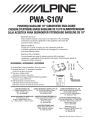
PWA-S10V
POWERED BASSLINE 10" SUBWOOFER ENCLOSURE
CAISSON D'EXTREME GRAVE BASSLINE DE 10 PO ALIMENTECAISSON
CAJA ACUSTICA PARA SUB WOOFER POTENCIADO BASSLINE DE 10"
OWNER'S MANUAL
Please read this manual to maximize your enjoyment of the outstanding
performance and feature capabilities of the equipment, then retain the
manual for future reference.
•
MODE D'EMPLOI
Veuillez lire ce mode d' emploi pour tirer pleinement profit des
excellentes performances et fonctions de cet appareil, et conservez-le
pour toute reference future.
MANUAL DEL USUARIO
Lea esta manual para sacar el maximo provecho del excepcional
rendimiento y capacidad de funcionamiento del equipo. Posteriormente, guarde el
manual para futura referencia.
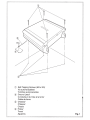
ACCESSORIES I ACCESSOIRES I ACCESORIOS
CD Mounting Plates I Plaques d'assemblage I Placas de montaje
(2) Mounting Plate Screws /Vis des plaques d'assemblage I
Tornillos de las placas de montaje
@ Wrre zip tie I Attaches de cable I
Abrazaderas de plastico para cables
@ MRV-M250 Owner's Manual I MRV-M250 Manuel du proprietaire I
Manual del usuario MRV-M250
@ MRV-M250 Speaker Level Input Harness I
MRV-M250 Faisceau d'entree pour haut-parleur I
MRV-M250 Conector de entrada de nivel de la bocina
ALPINE ELECTRONICS, INC.
1-7, Yukigaya-Otsukamachi, Ota-ku
Tokyo 145-0067, Japan
Tel.: 0570-006636
ALPINE ELECTRONICS OF AUSTRALIA PTY. LTD.
161-165 Princes Highway, Hallam
Victoria 3803, Australia
Tel.: (03) 8787-1200
ALPINE ELECTRONICS OF AMERICA, INC. ALPINE ELECTRONICS DE ESPANA, S.A.
Portal de Gamarra 36, Pabell6n, 32
19145 Gramercy Place
01 013 Vitoria {Aiava).
Torrance, California 90501 U.S.A.
APDO 133, Spain
Tel.: 1-800-ALPINE-1 (1-800-257-4631)
Tel.: (945) 283-588
ALPINE ELECTRONICS GmbH
Wilhelm-Wagenfeld-Strase 1-3
80807 MOnchen, Germany
Tel.: (089)-324-2640
(2)
TTT
TTT
ALPINE ELECTRONICS OF U.K., LTD.
Alpine House Earlplace Business Park
Fletchamstead Highway,
Coventry CV4 9TW, United Kingdom
Tel.: (0845) 313-1650
ALPINE ELECTRONICS FRANCE S.A.R.L.
98, Rue de Ia Belle Etoile, Z.l. Paris Nord II,
B.P. 50016, 95945 Roissy Charles de
Gaulle Cedex, France
Tel.: (01) 4863-8989
ALPINE ITALIA S.p.A.
Viale C. Colombo 8, 20090 Trezzano Sui
Naviglio (MI), Italy
Tel.: (02) 484-781
Designed by Alpine Electronics of America, Inc.
ENGLISH
INTRODUCTION: Please read this OWNER'S MANUAL thoroughly to familiarize yourself with each control and function.
We at ALPINE hope that your new PWA-S1 OV will give you
many years of listening enjoyment. In case of problems when
installing your PWA-S1 OV, please contact your authorized
ALPINE dealer.
CAUTION: These controls are for tuning your system.
Please consult your authorized Dealer for adjustment.
IMPORTANT NOTICE!
1. Do not over-drive the amplifier. Over-driving the amplifier
will result in distortion or clipping and can damage any
speaker.
2. Make sure gain controls are properly set. (Follow instructions in amplifier owner's manual.)
3. Make sure that the speaker is properly rated for the
amplifier.
4. Make sure that volume. bass, treble, equalization or crossover settings do not cause the amplifier to over-drive.
FAILURE TO FOLLOW THESE GUIDELINES MAY RESULT
IN BURNED OR DAMAGED SPEAKER VOICE COILS WHICH
WILL VOID YOUR WARRANTY.
6
WARNING
~CAUTION
This symbol means important
instructions. Failure to heed them
can result in serious injury or death.
This symbol means important
instructions. Failure to heed them
can result in injury or poperty
~
~WARNING
DO NOT OPERATE ANY FUNCTION THAT TAKES YOUR ATTENTION
AWAY FROM SAFELY DRIVING YOUR VEHICLE.
Any function that requires your prolonged attention should only be
performed after coming to a complete stop. Always stop the vehicle in
a safe location before performing these functions. Failure to do so may
result in an accident.
KEEP THE VOLUME AT A LEVEL WHERE YOU CAN STILL HEAR
OUTSIDE NOISE WHILE DRIVING.
Excessive volume levels that obscure sounds such as emergency vehicle
sirens or road warning signals (train crossings, etc.) can be dangerous
and may result in an accident. LISTENING AT LOUD VOLUME LEVELS IN A
VEHICLES MAY ALSO CAUSE HEARING DAMAGE.
DO NOT DISASSEMBLE OR ALTER.
Doing so may result in an accident, fire or electric shock.
USE THIS PRODUCT FOR MOBILE 12V APPLICATIONS.
Use for other than its designed application may result in
fire, electric shock or other injury.
USE THE CORRECT AMPERE RATING WHEN REPLACING FUSES.
Failure to do so may result in fire or electric shock.
DO NOT BLOCK VENTS OR RADIATOR PANELS.
Doing so may cause heat to build up inside and may result in fire.
MAKE THE CORRECT CONNECTIONS.
Failure to make the proper connections may result in fire or product
damage.
2-EN
USE ONLY IN VEHICLES WITH A 12 VOLT NEGATIVE GROUND.
(Check with your dealer if you are not sure.) Failure to do so may result in fire, etc.
BEFORE WIRING, DISCONNECT THE CABLE FROM THE POSITIVE
BATTERY TERMINAL.
Failure to do so may result in electric shock or injury due to electrical
shorts.
DO NOT ALLOW CABLES TO BECOME ENTANGLED IN SURROUNDING
OBJECTS.
Arrange wiring and cables in compliance with the manual to prevent
obstructions when driving. Cables or wiring that obstruct or hang up on
places such as the steering wheel, gear lever, brake pedals, etc. can be
extremely hazardous.
DO NOT SPLICE INTO ELECTRICAL CABLES.
Never cut away cable insulation to supply power to other equipment.
Doing so will exceed the current carrying capacity of the wire and result
in fire or electric shock.
DO NOT DAMAGE PIPE OR WIRING WHEN DRILLING HOLES.
When drilling holes in the chassis for installation, take precautions so as
not to contact, damage or obstruct pipes, fuel lines, tanks or electrical
wiring. Failure to take such precautions may result in fire.
DO NOT USE BOLTS OR NUTS IN THE BRAKE OR STEERING SYSTEMS
TO MAKE GROUND CONNECTIONS.
Bolts or nuts used for the brake or steering systems (or any other safety-related
system), or tanks should NEVER be used for installations or ground connections.
Using such parts could disable control of the vehicle and cause fire etc.
KEEP SMALL OBJECTS SUCH AS BOLTS OR SCREWS OUT OF THE
REACH OF CHILDREN.
Swallowing them may result in serious injury. If swallowed, consult a
physician immediately.
~CAUTION
HALT USE IMMEDIATELY IF A PROBLEM APPEARS.
Failure to do so may cause personal injury or damage to the product.
Return it to your authorized Alpine dealer or the nearest Alpine Service
Center for repairing.
HAVE THE WIRING AND INSTALLATION DONE BY EXPERTS.
The wiring and installation of this unit requires special technical skill
and experience. To ensure safety, always contact the dealer where you
purchased this product to have the work done.
USE SPECIFIED ACCESSORY PARTS AND INSTALL THEM SECURELY.
Be sure to use only the specified accessory parts. Use of other than
designated parts may damage this unit internally or may not securely
install the unit in place. This may cause parts to become loose resulting
in hazards or product failure.
ARRANGE THE WIRING SO IT IS NOT CRIMPED OR PINCHED BY A
SHARP METAL EDGE.
Route the cables and wiring away from moving parts (like the seat rails)
or sharp or pointed edges. This will prevent crimping and damage to the
wiring. If wiring passes through a hole in metal, use a rubber grommet
to prevent the wire's insulation from being cut by the metal edge of
the hole.
DO NOT INSTALL IN LOCATIONS WITH HIGH MOISTURE OR Dust
Avoid installing the unit in locations with high incidence of moisture or
dust. Moisture or dust that penetrates into this unit may result in product
failure.
FRAN~AIS
INTRODUCTION: Priere de lire attentivement ce MODE
D'EMPLOI pour se familiariser avec chaque commande et fonction. Chez Alpine, nous esperons que le nouveau PWA-S1 OV
donnera de nombreuses annees de plaisir d'ecoute.
En cas de problemes Iars de !'installation du PWA-S1 OV, priere
de contacter le revendeur agree d'ALPINE.
PRECAUTION: Ces commandes sont utilisees pour Ia
syntonisation du systeme. Priere de contacter le revendeur
agree pour le reglage.
AVIS IMPORTANT!
1. Ne pas surmener l'amplificateur. Surmener l'amplificateur
entralnera de Ia distorsion ou des coupures et peut
endommager le haut-parleur.
2. S'assurer que Ia regulation de gain est bien reglee.
(Suivre les instructions du manuel du proprietaire de
l'amplificateur.)
3. S'assurer que le haut-parleur est approprie pour
l'amplificateur.
4. S'assurer que les reglages de volume, de basse,
d'egalisation ou de filtre passif n'entralnent pas de
surmenage de l'amplificateur.
OMETTRE DE SUIVRE CES DIRECTIVES PEUT ENTRAiNER
LA COMBUSTION OU L'ENDOMMAGEMENT DE LA BOBINE
ACOUSTIQUE CE QUI ANNULERAIT VOTRE GARANTIE.
~
AVERTISSEMENT
~ATTENTION
Ce symbole designe des instructions
importantes. Le nonrespect de ces
instructions peut entrainer de graves
blessures, voire Ia mort.
Ce symbole designe des instructions
importantes. Le nonrespect de ces
instructions peut entrainer des blessures
ou des dommages materiels.
~ AVERTISSEMENT
N'ACTIVER AUCUNE FONCTION SUSCEPTIBLE DE DETOURNER VOTRE
ATTENTION DE LA CONDUITE DU VEHICULE.
Les fonctions requerant une attention prolongee ne doivent etre
exploitees qu'a !'arret complet du vehicule. Toujours arreter le vehicule
a un endroit sOr avant d'activer ces fonctions. II y a risque de provoquer
un accident.
GARDER LE VOLUME A FAIBLE NIVEAU DE MANIERE A POUVOIR
ENTENDRE LES BRUITS EXTERIEURS PENDANT LA CONDUITE.
Les niveaux de volumes excessifs, tels que les sirenes de vehicules
d'urgences ou les signaux routiers d'avertissement (passage a niveau des
trains, etc.), qui submergent les sons, peuvent etre dangereux et causer
des accidents. L'ECOUTE ADES NIVEAUX DE VOLUME ELEVES DANS UN
VEHICULE PEUT ENTRATNER DES TROUBLES D'AUDITION.
NE PAS DESASSEMBLER Nl MODIFIER L' APPAREIL.
II y a risque d'accident, d'incendie ou de choc electrique.
UTILISER CET APPAREIL POUR DES APPLICATIONS MOBILES DE 12 V.
Toute utilisation autre que !'application designee comporte un risque
d'incendie, de choc electrique ou de blessure.
UTILISER DES FUSIBLES DE L' AMPERAGE APPROPRIE.
II y a risque d'incendie ou de decharge electrique.
NE PAS OBSTRUER LES SORTIES D'AIR Nl LES PANNEAUX DU RADIATEUR.
Une surchauffe interne peut se produire et provoquer un incendie.
EFFECTUER CORRECTEMENT LES CONNEXIONS.
II y a risque de blessures ou de dommages a l'appareil.
UTILISER UNIQUEMENT DANS DES VEHICULES POSSEDANT UNE MISE
ALA TERRE NEGATIVE DE 12 VOLTS
(Verifiez aupres de votre concessionnaire si vous n'en etes pas certain.)
II y a risque d'incendie, etc.
AVANT TOUTE CONNEXION, DEBRANCHER LE CABLE DE LA BORNE
POSITIVE DE LA BATTERIE.
II y a risque de choc electrique ou de blessure par courts-circuits.
NE PAS COINCER LES CABLES AVEC DES OBJETS VOISINS.
Positionner les cables conformement au manuel de maniere a eviter toute
obstruction en cours de conduite. Les cables qui obstruent ou depassent a des
endroits tels que le volant, le levier de changement de vitesses, Ia J)OOale de
frein, etc., peuvent s'averer extremement dangereux.
NE PAS DENUDER LES CABLES ELECTRIQUES.
Ne jamais enlever Ia gaine isolante pour alimenter un autre appareil.ll y a risque de
depassement de Ia capacite de courant et, partant, d'incendie ou de choc eleclrique.
NE PAS ENDOMMAGER DE CONDUITES Nl DE CABLES LORS DU
FORAGE DES TROUS.
Lors du forage de trous dans le chassis en vue de !'installation, veiller
a ne pas entrer en contact, endommager ni obstruer de conduites,
de tuyaux a carburant ou de fils electriques. Le non-respect de cette
precaution peut entrainer un incendie.
NE PAS UTILISER DES ECROUS Nl DES BOULONS DU CIRCUIT DE
FREINAGE OU DE DIRECTION POUR LES CONNEXIONS DE MASSE.
Les boulons et les ecrous utilises pour les circuits de freinage et de
direction (ou de tout autre systeme de securite) ou lesreservoirs ne
peuvent JAMAIS etre utilises pour I' installation ou Ia liaison a Ia masse.
L'utilisation de ces organes peut desactiver le systeme de controle du
vehicule et causer un incendie, etc.
GARDER LES PETITS OBJETS COMME LES BOULONS OU LES VIS HORS
DE PORTEE DES ENFANTS.
L'ingestion de tels objets peut entrainer de graves blessures. En cas
d'ingestion, consulter immediatement un medecin.
~ATTENTION
INTERROMPRE TOUTE UTILISATION EN CAS DE PROBLEME.
Le non-respect de cette precaution peut entrainer des blessures ou
endommager l'appareil. Retourner l'appareil aupres du distributeur Alpine
agree ou un centre de service apres-vente Alpine en vue de Ia reparation
FAIRE INSTALLER LE CABLAGE ET L' APPAREIL PAR DES EXPERTS.
Le cablage et !'installation de cet appareil requiert des competences
techniques et de I' experience. Pour garantir Ia securite,faire proceder a
!'installation de cet appareil par le distributeur qui vous l'a vendu.
UTIUSER LES ACCESSOIRES SPECIRES ET LES INSTAllER CORRECTEMENT.
Utiliser uniquement les accessoires specifies. L'utilisation d'autres
composants que les composants specifies peut causer des dommages
internes a cet appareil ou son installation risque de ne pas etre effectuee
correctement. Les pieces utilisees risquent de se desserrer et de
provoquer des dommages ou une defaillance de l'appareil.
FAIRE CHEMINER LE CABLAGE DE MANIERE A NE PAS LE COINCER
CONTRE UNE ARETE METALLIQUE.
Faire cheminer les cables al'ecart des pieces mobiles (comme les rails d'un
siege) et des aretes acerees ou pointues. Cela evitera ainsi de coincer et
d'endommager les cables. Si un cable passe dans un orifice metallique, utiliser
un passe-cloison en caoutchouc pour eviter que Ia gaine isolante du cable ne soit
endommagee par le rebord metallique de !'orifice.
NE PAS INSTALLER A DES ENDROITS TRES HUMIDES OU POUSSIEREUX.
Eviter d'installer l'appareil a des endroits soumis a une forte humidite ou
a de Ia poussiere en exces. La penetration d'humidite ou de poussiere a
l'interieur de cet appareil risque de provoquer une defaillance.
3-FR
ESPANOL
INTRODUCCION: Lea este MANUAL DEL USUARIO detenidamente para familiarizarse con cada control y funci6n.
En ALPINE deseamos que su nuevo PWA-S1 OV le brinde
muchos aiios de entretenimiento auditive. En el caso de tener
problemas con Ia instalaci6n de su PWA-S1 OV, comunlquese
con su distribuidor autorizado de ALPINE.
PRECAUCION: Estos controles son para Ia afinaci6n de su sistema.Consulte con su distribuidor autorizado para realizar ajustes.
iAVISO IMPORTANTE!
1. No use el amplificador a mayor capacidad de lo normal.
Hacerlo podrfa ocasionar distorsi6n o recorte y puede
dafiar cualquier bocina.
2. Verifique que los controles de ganancia esten
configurados adecuadamente. (Siga las instrucciones
en el manual del usuario del amplificador).
3. Verifique que Ia bocina tenga Ia clasificaci6n adecuada
para el amplificador.
4. Verifique que Ia configuraci6n del volumen, bajos,
graves, agudos, ecualizaci6n o divisor de frecuencia no
use el amplificador a mayor capacidad de lo normal.
EL INCUMPLIMIENTO DE ESTAS PAUTAS PUEDE
PROVOCAR QUEMADURAS 0 DANOS A LA BOBINA DE
VOZ DE LA BOCINA Y ANULAR SU GARANTiA.
~ ADVERTENCIA
~ PRECAUCION
Este slmbolo indica que las
instrucciones son importantes. De
no tenerse en cuenta, se podrlan
ocasionar lesiones graves o Ia
muerte.
Este slmbolo indica que las
instrucciones son importantes. De
no tenerse en cuenta, se podrlan
ocasionar lesiones graves o
danos materiales.
~ ADVERTENCIA
NO UTILICE NINGUNA FUNCit'lN QUE DISTRAIGA SU ATENCit'lN DE UNA
CONDUCCit'lN SEGURA DEL VEH(CULO.
Cualquier funcion que requiera una atencion prolongada deberia
realizarse despues de detener el vehfculo completamente. Detenga
siempre el vehfculo en un Iugar seguro antes de realizar estas funciones.
De no ser asf, podrfa ocasionar un accidente.
MANTENGA EL VOLUMEN EN UN NIVEL EN EL QUE AUN PUEDA
ESCUCHAR RUIDOS EXTERNOS DURANTE LA CONDUCCit'lN.
Los niveles de volumen excesivamente altos que impiden ofr sonidos
como sirenas de vehfculos de emergencia o sefiales de aviso en Ia
carretera (cruces de trenes, etc.) pueden ser peligrosos y podrfan
ocasionar un accidente. LOS NIVELES DE VOLUMEN ALTOS EN UN
VEHiCULO PUEDEN PROVO CAR PERDIDA AUDITIVA.
NO DESARME Nl ALTERE LA UNlOAD.
Si lo hiciera, podrfa ocasionar un accidente, un incendio o una descarga electrica.
UTILICE ESTE PRODUCTO CON APLICACIONES Mt'lVILES DE 12 V.
Si se em plea para otra aplicacion distinta de Ia prevista, podrfa
producirse un incendio, una descarga electrica u otras lesiones.
UTILICE EL AMPERAJE CORRECTO AL SUSTITUIR LOS FUSIBLES.
De no ser asf, podrfa ocasionar un incendio o una descarga electrica.
NO OBSTRUYA LOS ORIRCIOS DE VENTILACit'lN 0 LOS PANELES DEL RADIADOR.
Si los bloquea, el calor podrfa acumularse en el interior y producir un incendio.
REALICE LAS CONEXIONES CORRECTAMENTE.
Una conexion incorrecta puede producir un incendio o dafiar el equipo.
4-ES
UTILICE LA UNlOAD SOLAMENTE EN VEH(CULOS CON CONEXIt'lN A
TIERRA NEGATIVA DE 12 VOLTIOS.
(Consulte a su distribuidor en caso de duda.) De no ser asf, podrfa
ocasionar un incendio, etc.
ANTES DE EFECTUAR EL CABLEADO, DESCONECTE EL CABLE DEL
TERMINAL POSITIVO DE LA BATER(A.
De no hacerlo asf, podrfa ocasionar una descarga electrica o heridas
debido a cortocircuitos electricos.
NO PERMITA QUE LOS CABLES SE ENREDEN CON LOS OBJETOS
SITUADOS ALREDEDOR.
Disponga Ia instalacion electrica y los cables conforme a lo descrito en
el manual para evitar obstaculos durante Ia conducci6n. Los cables que
obstaculizan Ia conduccion o que cuelgan de partes del vehfculo como el
volante de direcci6n, Ia palanca de cambios, los pedales de freno, etc.,
se consideran extremadamente peligrosos.
NO EMPALME CABLES ELECTRICOS.
Nunca corte el aislamiento de un cable para suministrar energfa a otro
equipo. Esto hace que Ia capacidad portadora del cable se supere y
puede ser Ia causa de incendios o descargas electricas.
EVITE DANAR LOS TUBOS Y EL CABLEADO CUANDO TALADRE AGUJEROS.
Si taladra agujeros en el chasis durante Ia instalacion, tome las
precauciones necesarias para no rozar, dafiar u obstruir los tubos, las
tuberfas de combustible, los depositos o el cableado electrico. De lo
contrario, podrfa provocar un incendio.
NO UTILICE TUERCAS 0 PERNOS EN EL SISTEMA DE FRENOS 0 DE
DIRECCit'lN PARA REALIZAR LAS CONEXIONES A MASA.
Los pernos o tuercas empleados en los sistemas de freno o de direcci6n
(o en cualquier otro sistema relacionado con Ia seguridad del vehfculo),
o los depositos, NUNCA deben utilizarse para instalaciones de cableado
o conexi6n a masa. Si utiliza tales partes podra incapacitar el control del
vehfculo y provocar un incendio, etc.
MANTENGA LOS OBJETOS PEQUENOS, COMO LOS PERNOS 0
TORNILLOS, FUERA DEL ALCANCE DE LOS NINOS.
La ingestion de estos objetos puede provocar lesiones graves. En caso
de ingestion consulte con un medico inmediatamente.
~ PRECAUCION
DETENGA EL FUNCIONAMIENTO INMEDIATAMENTE Sl SURGE UN
PROBLEMA.
De no ser asf, podrfa ocasionar lesiones personales o dafios en el
producto. Devuelva el producto al proveedor Alpine o al Servicio Tecnico
Alpine mas cercano para que lo reparen.
CONF(E EL CABLEADO Y LA INSTALACit'lN A PROFESIONALES.
El cableado y Ia instalaci6n de esta unidad requieren una competencia
y experiencia tecnica confirmada. Para garantizar Ia seguridad, p6ngase
siempre en contacto con el distribuidor al que ha com prado el equipo
para confiarle estas tareas.
UTILICE LOS ACCESORIOS ESPECIFICADOS E INSTALELOS
CORRECTAMENTE.
Asegurese de utilizar los accesorios especificados solamente. La
utilizaci6n de otras piezas no designadas puede ser Ia causa de dafios en
el interior de Ia unidad o de una instalaci6n incorrecta. Las piezas pueden
aflojarse, lo que, ademas de ser peligroso, puede provocar averfas.
DISPONGA EL CABLEADO DE FORMA QUE LOS CABLES NO SE
DOBLEN, NO SE CONTRAIGAN Nl ROCEN UN BORDE METALICO
AFILADO.
Aleje los cables y el cableado de piezas moviles (como los rafles de los
asientos) o de bordes puntiagudos o afilados. De esta forma evitara
dobleces y dafios en el cableado. Si los cables se introducen por un
orificio de metal, uti lice una arandela de goma para evitar que el borde
metalico del orificio corte el aislamiento del cable.
NO INSTALE LA UNlOAD EN LUGARES MUY HUMEDOS 0 LLENOS DE POLVO.
Evite instalar Ia unidad en lugares con altos indices de humedad o polvo.
Si entra polvo o humedad, Ia unidad puede averiarse.
ENGLISH
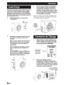
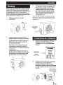
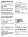
Mounting
Due to the high output of the PWA-S1 OV, the round port
opening should not be obstructed when the system is in
operation. Some heat is produced when the system is in
operation. Therefore, the MRV-M250 amplifier should not
be obstructed, allowing for free circulation of air. For proper
installation please contact your authorized Alpine dealer.
1
Gently remove the amplifier cover
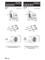
3.
Once the plates are mounted as
shown,position the PWA-S1 OV in the
desired location within the vehicle. Before
securing with screws, check to make sure
all screws can affix to a structurally solid
surface while avoiding vehicle wiring,
components, etc.
Note: For securing the mounting plates to the
vehicle, it may be necessary to use longer screws (not
included) to accommodate carpet thickness, etc.
Port Opening
Recommended
Min. Clearance
4"
2
Position the enclosure so the mounting
brackets can be installed.
Caution: Take care to avoid personal injury
or damage to this product/your vehicle
during handling
Wiring Connections
1
Attach the included mounting plates to the
bottom of the enclosure with the supplied
screws
WARNING: Make sure to use the screws
provided for mounting the plate to the
enclosure to avoid potential damage to
internal parts.
Wiring the amplifier to the vehicle. Please
refer to the "amplifier connection" portion
in the included MRV-M250 manual.
Refer to
MRV-M250
Owner's Manual
2
MRV-M250
After making all the connections re-install
the amplifier cover by aligning the steel
pins with the rubber grommets and press
firmly at each corner until panel is firmly
seated.
Strain Relief Holes* for
Power/Ground Cables
*Plastic Zip Tie Included
\l@
I
'
1/
(
I
5-EN
FRAN~AIS
Assemblage
Etant donne le niveau eleve de sortie du PWA-S1 OV, l'ouverture
ronde de port ne doit pas etre obstruee lorsque le systeme
est en fonction. Le systeme produit une certaine quantite de
chaleur durant son fonctionnement. De ce fait, l'amplificateur
MRV-M250 ne doit pas etre obstrue et Ia circulation d'air doit
etre possible. Veuillez contacter votre distributeur agree Alpine
pour une installation correcte.
1
Retirer delicatement le couvercle de
l'amplificateur
3.
Une fois que les plaques sont installees
com me illustrees, placer le PWAS1 OV a
l'emplacement souhaite a l'interieur du
vehicule. Avant de mettre les vis, s'assurer
que celles-ci puissent etre fixees sur une
surface solide tout en evitant le cablage et
les composants du vehicule.
Remarque : De far;on afixer les plaques de montage, if peut
etre necessaire d 'utiliser des vis plus longues (non inc/uses)
pours 'adapter aI'epaisseur du tapis, etc.
Degagement
minimal de
10 em (4 po)
Recommande
Pour l'ouverture
du port
2
Positionner le caisson de fa~on a ce que
les supports de fixation puissent etre
installes.
Mise en garde : Prendre soin d'eviter les
blessures corporelles ou les dommages
ce produit ou au vehicule durant Ia
manipulation.
· Connexions de COblage
1
a
Fixer les plaques de montage au bas du
caisson a l'aide des vis fournies a cet
effet.
Relier a l'aide d'un cable l'amplificateur au
vehicule. Veuillez vous reporter a Ia section
sur Ia cc connexion de l'amplificateur » dans
le manuel inclus avec le MRV-M250.
Consultez Ia
MRV-M250
Manuel du
proprietaire
AVERTISSEMENT : Assurer d'utiliser les
vis fournies pour installer Ia plaque sur le
caisson de fa~on a eviter les dommages
potentials aux pieces internes.
2
MRV·M250
Apres avoir effectue toutes les
connexions, reinstaller le couvercle de
l'amplificateur en alignant les tiges d'acier
avec les oeillets en caoutchouc et appuyer
fermement sur chaque coin jusqu'a ce que
le panneau soit bien enclenche.
Trous de soulagement de
traction* pour les cables
d'alimentation/mise Ia terre
* Attaches en plastique
incluses
a
6-FR
ESPANOL
Montaje
3.
Debido a Ia alta salida del PWA-S1 OV, Ia abertura del puerto
redondo no debe estar obstruida cuando el sistema este en
funcionamiento. El sistema produce calor cuando se encuentra
en funcionamiento. Por lo tanto, no se debe obstruir el
amplificador M~V-M250, para ~sl ~er~itir Ia libre circulaci6.n
del aire. Comumquese con su d1stnbU1dor autonzado de Alpme
para informacion sobre Ia instalaci6n correcta.
1
Retire con cuidado Ia tapa del
amplificador
Una vez que las placas se monten segun
Ia ilustraci6n, coloque el PWA-S10V en
el Iugar deseado dentro del vehlculo.
Antes de ajustar los tornillos, verifique
que todos los tornillos pueden quedar
fijos a una superficie estructuralmente
s61ida, evitando cables del vehiculo,
componentes, etc.
Nota: Para fijar las placas de montaje al vehiculo,
puede que sea necesario usar tornillos mas largos
(no vienen incluidos) para ajustarse al grosor de Ia
alfombra, etc.
Abertura del puerto
Mfnimo espacio libre
recomendado
4"
2
Coloque Ia bocina de manera que se
puedan instalar los soportes de montaje.
Fije las placas de montaje incluidas a Ia
parte inferior de Ia bocina usando los
tornillos suministrados.
Conexiones de cableado
1
Precauci6n: Tome precauciones para
evitar lesiones personales o daflos a
este producto o a su vehiculo durante Ia
manipulaci6n
Cableado del amplificador al vehiculo.
Consulte Ia secci6n "conexi6n del
amplificador" en el manual MRV-M250
incluida.
MRV·M250
ADVERTENCIA: Asegurese de usar los
tornillos proporcionados para el montaje
de las placas a Ia bocina, a fin de evitar
posibles daiios a las partes internas.
Consulte el
manual del
usuario
MRV-M250
,,,
2
Despues de hacer todas las conexiones,
reinstale Ia tapa del amplificador,
alineando los pines de acero con las
arandelas de goma y presione firmemente
en cada esquina hasta que el panel quede
bien fijo.
Orificios para alivio de
tension* para Cables de
alimentaci6n/a tierra.
*lncluye Ia abrazadera
de plastico.
\t@)
I
I
.1
7-ES
FRANt;AIS
ENGLISH
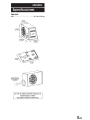
Specifications
Specifications
PWA-S10V:
PWA-S10V::
Weight.. .................................................... 15.80 kg (34. 70 lbs)
Poids ................................................... 34.70 livres (15.80 kg)
350mm
(13-13/16")
350 mm
(13-13/16")
···· ·
~
~
····~~~
100 mm
(3-15116") ·············
e;;
(1-3/8")
······~·······'"'~be;;
·.
·.~·
...
\
For product improvement, specifications and design
are subject to change without notice.
(1-3/8")
(3·15116") ············· ... ..
·.
~~\
~~~")
~~n61
Port Opening
Recommended
Min. Clearance
4"
8-ENIFR
100 mm
.
....
Degagement
minimal de
10 em (4 po)
Recommande
Pour l'ouverture
du port
Pour !'amelioration des produits, les changements dans
les specifications et Ia conception peuvent etre
apportes sans preavis.
ESPANOL
. Especificaciones
PWA-S10V:
Peso ....................................................... 34.70 lbs (15.80 kg)
350mm
(13-13/16")
Abertura del puerto
Mlnimo espacio libre
recomendado
4"
Con el fin de continuar mejorando el producto, las
especificaciones y el diseno
estan sujetos a cambios sin previo aviso.
9-ES
FOR CAR USE ONLY/POUR APPLICATION AUTOMOBILE UNIQUEMENT/PARA USO EN AUTOMOVILES
MRV-M250
MONO POWER AMPLIFIER
• OWNER'S MANUAL
Please read this manual to maximize your enjoyment
of the outstanding performance and feature capabilities
of the equipment, then retain the manual for future
reference.
• MODE D'EMPLOI
Veuillez lire ce mode d'emploi pour tirer pleinement
profit des excellentes performances et fonctions de cet
appareil, et conservez-le pour toute reference future.
• MANUAL DE OPERACION
Lea este manual, por favor, para disfrutar al maximo
de las excepcionales prestaciones y posibilidades
funcionales que ofrece el equipo, luego guarde el manual
para usarlo como referencia en el futuro.
ALPINE ELECTRONICS MARKETING, INC.
1-7, Yu kigaya -Otsu kamach i, Ota -ku,
Tokyo 145-0067, JAPAN
Phone: 03-5499-4531
ALPINE ELECTRONICS GmbH
Wilhelm-Wagenfeld-Str. 1-3,
80807 MOnchen, Germany
Phone 089-32 42 640
ALPINE ITALIA S.p.A.
Viale C. Colombo 8, 20090
Trezzano Sui Naviglio (MI), Italy
Phone 02-484781
ALPINE ELECTRONICS OF AMERICA, INC.
19145 Gramercy Place, Torrance,
California 90501, U.S.A.
Phone 1-800-ALPINE-1 (1-800-257-4631)
ALPINE ELECTRONICS OF U.K. LTD.
Alpine House
Fletchamstead Highway,
Coventry CV4 9TW, U.K.
Phone 0870-33 33 763
ALPINE ELECTRONICS DE ESPANA, S.A.
Portal de Gamarra 36,
Pabell6n, 32
01 013 Vito ria (Aiava) - APDO
133, Spain
Phone 945-283588
ALPINE ELECTRONICS OF AUSTRALIA PTY. LTD.
161-165 Princes Highway, Hallam
Victoria 3803, Australia
Phone 03-8787-1200
Qingdao Dongli Xinhaiyuan
Printing Co., Ltd.
No.1?, jiushuidong road,
Qingdao, China
ALPINE ELECTRONICS FRANCE S.A.R.L.
(RCS PONTOISE B 338 101 280)
98, Rue de Ia Belle Etoile,
Z.l. Paris Nord II, B.P. 50016,
95945 Roissy Charles de Gaulle
Cedex, France
Phone 01-48638989
Designed by ALPINE Japan
Printed in China (Y_A2A)
68-21 057Z97-C
M3514501 01 B
ENGLISH
Introduction:
Please read this OWNER'S MANUAL thoroughly to familiarize yourself with each control and function. We at
ALPINE hope that your new MRV-M250 will give you many years of listening enjoyment.
In case of problems when installing your MRV-M250, please contact your authorized ALPINE dealer.
CAUTION: These controls are for tuning your system. Please consult your authorized Dealer for
adjustment.
&wARNING
This symbol means important instructions.
Failure to heed them can result in serious injury or death.
&cAUTION
This symbol means important instructions.
Failure to heed them can result in injury or property damages.
&wARNING
• DO NOT OPERATE ANY FUNCTION THAT TAKES YOUR ATTENTION AWAY FROM SAFELY DRIVING
YOUR VEHICLE. Any function that requires your prolonged attention should only be performed after coming
to a complete stop. Always stop the vehicle in a safe location before performing these functions. Failure to do
so may result in an accident.
• KEEP THE VOLUME AT A LEVEL WHERE YOU CAN STILL HEAR OUTSIDE NOISES WHILE DRIVING.
Excessive volume levels that obscure sounds such as emergency vehicle sirens or road warning signals
(train crossings, etc.) can be dangerous and may result in an accident. LISTENING AT LOUD VOLUME
LEVELS IN A CAR MAY ALSO CAUSE HEARING DAMAGE.
• DO NOT DISASSEMBLE OR ALTER. Doing so may result in an accident, fire or electric shock.
• USE THIS PRODUCT FOR MOBILE 12V APPLICATIONS. Use for other than its designed application may
result in fire, electric shock or other injury.
• USE THE CORRECT AMPERE RATING WHEN REPLACING FUSES. Failure to do so may result in fire or
electric shock.
• DO NOT BLOCK VENTS OR RADIATOR PANELS. Doing so may cause heat to build up inside and may
result in fire.
• MAKE THE CORRECT CONNECTIONS. Failure to make the proper connections may result in fire or product
damage.
• USE ONLY IN CARS WITH A 12 VOLT NEGATIVE GROUND. (Check with your dealer if you are not sure.)
Failure to do so may result in fire, etc.
• BEFORE WIRING, DISCONNECT THE CABLE FROM THE NEGATIVE BATTERY TERMINAL. Failure to do
so may result in electric shock or injury due to electrical shorts.
• DO NOT ALLOW CABLES TO BECOME ENTANGLED IN SURROUNDING OBJECTS. Arrange wiring and
cables in compliance with the manual to prevent obstructions when driving. Cables or wiring that obstruct or
hang up on places such as the steering wheel, gear lever, brake pedals, etc. can be extremely hazardous.
• DO NOT SPLICE INTO ELECTRICAL CABLES. Never cut away cable insulation to supply power to other
equipment. Doing so will exceed the current carrying capacity of the wire and result in fire or electric shock.
• DO NOT DAMAGE PIPE OR WIRING WHEN DRILLING HOLES. When drilling holes in the chassis for
installation, take precautions so as not to contact, damage or obstruct pipes, fuel lines, tanks or electrical
wiring. Failure to take such precautions may result in fire.
• DO NOT USE BOLTS OR NUTS IN THE BRAKE OR STEERING SYSTEMS TO MAKE GROUND
CONNECTIONS. Bolts or nuts used for the brake or steering systems (or any other safety-related system) , or
tanks should NEVER be used for installations or ground connections. Using such parts could disable control
of the vehicle and cause fire etc.
• KEEP SMALL OBJECTS SUCH AS BOLTS OR SCREWS OUT OF THE REACH OF CHILDREN.
Swallowing them may result in serious injury. If swallowed, consult a physician immediately.
&cAUTION
• HALT USE IMMEDIATELY IF A PROBLEM APPEARS. Failure to do so may cause personal injury or
damage to the product. Return it to your authorized Alpine dealer or the nearest Alpine Service Center for
repairing .
• HAVE THE WIRING AND INSTALLATION DONE BY EXPERTS. The wiring and installation of this unit
requires special technical skill and experience. To ensure safety, always contact the dealer where you
purchased this product to have the work done.
• USE SPECIFIED ACCESSORY PARTS AND INSTALL THEM SECURELY. Be sure to use only the specified
accessory parts. Use of other than designated parts may damage this unit internally or may not securely
install the unit in place. This may cause parts to become loose resulting in hazards or product failure.
• ARRANGE THE WIRING SO IT IS NOT CRIMPED OR PINCHED BY A SHARP METAL EDGE. Route the
cables and wiring away from moving parts (like the seat rails) or sharp or pointed edges. This will prevent
crimping and damage to the wiring. If wiring passes through a hole in metal, use a rubber grommet to prevent
the wire's insulation from being cut by the metal edge of the hole.
• DO NOT INSTALL IN LOCATIONS WITH HIGH MOISTURE OR DUST. Avoid installing the unit in locations
with high incidence of moisture or dust. Moisture or dust that penetrates into this unit may result in product
failure.
SERVICE CARE
+
IMPORTANT NOTICE
SERIAL NUMBER:
INSTALLATION DATE:
INSTALLATION TECHNICIAN:
PLACE OF PURCHASE:
This Amplifier has been type tested and found to
comply with the limits for a Class B computing device
in accordance with the specifications in Subpart J
of Part 15 of FCC Rules. This equipment generates
and uses radio frequency energy, and it must be
installed and used properly in accordance with the
manufacturer's instructions.
+
+IMPORTANT
Please record the serial number of your unit in the
space provided here and keep it as a permanent
record. The serial number plate is located on the rear
of the unit.
For European Customers
Should you have any questions about warranty,
please consult your store of purchase.
+
For Customers in other Countries
IMPORTANT NOTICE
Customers who purchase the product with which this
notice is packaged, and who make this purchase in
countries other than the United States of America
and Canada, please contact your dealer for
information regarding warranty coverage.
SPECIFICATIONS
...
Performance
Power Output
THD+N
S/N Ratio
Frequency Response
Damping Factor
Control
Input Sensitivity
Crossover
Equalizer
Remote Level•
· .··. •·.. ''•· .:, / :·,_':, .:: ,,.•:•. ·.,;:·•·.',·::,,,;,.::;\'\\l..'iF;~ \.,.;,*•15\1' •·•<fr:r.i'
>85dB
>105dB
7Hz-400Hz
>500
·,
··, :.: ': ..
:•,.''•.';.c~·. · ••:: . ... •••··• ·';-,,•..-\':·:•;,;\.:',
RCA Input
Ref: Rated Power into 40
Speaker Level Input
Ref: Rated Power into 40
Variable LPF (-24dB/oct.)
Variable Bass EO (fc=50Hz)
Linear Attenuation
•Requires optional RUX-KNOB
0.15-4.0V
0.4-10V
50Hz-400Hz
o to +12dB
0 to -20dB
::
I
;width
Dimensions
150W RMS xI
250W RMS x 1
<:0.02%
<:0.03%
<:0.2%
<:0.3%
Ref: 40, 14.4V
Ref: 20, 14.4V
Ref: I OW into 40
Ref: I OW into 20
--::-·
Ref: Rated Power into 40
Ref: Rated Power into 20
IHF A-wtd + AES-17
Ref: 1W into 40
, IHF A-wtd + AES-17
Ref: Rated Power into 40
+0/-3dB, Ref: IW into 40
Ref: I OW into 40 at 1OOHz
General
Input Impedance
,;~:.<·"'
,•:•····.·· .:•.'t\-.':, i('"'' ,,;;:< • >.•:•·:.,,., ,;:".'.·L
... •·· ··._. • . ::· . ,. ••· ·
'·
!Overall
IHeatsink Only
Height
Depth
Weight
.•:"··· ····''
,, ·:
·····:··
,.;.: ::,
>10ko
190mm (7-1 /2")
155mm (6-1 /8")
55mm (2-3/16")
200mm (7-7/8")
1.5kg
NOTE:
• For product improvement, specifications and design are subject to change without notice.
ACCESSORIES
• Speaker Input Connector ............. .... ...... .................... ....................... .... .. ... ............................. .... .. .. ................ .............. .. ..... ... .1
• Self-Tapping Screw (M4 x 20)....
.. .. ..... .. .. .. . .......... ...... .............. ........................ ..... ..... ...... .... ........ .. ..... ....... ...........4
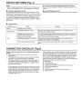
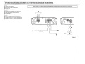
INSTALLATION (Fig. 1)
Due to the high power output of the MRV-M250, considerable heat is produced when the amplifier is in
operation. For this reason, the amplifier should be mounted in a location which will allow for free circulation of
air, such as inside the trunk. For alternate installation locations, please contact your authorized Alpine dealer.
1. Using the amplifier as a template, mark the four screw locations.
2. Make sure there are no objects behind the surface that may become damaged during drilling.
3. Drill the screw holes.
4. Position the MRV-M250 over the screw holes, and secure with four self-tapping screws.
NOTE:
• To securely connect the ground lead, use an already installed screw on a metal part of the vehicle (marked
(*))or a clean, bare metal spot on the vehicle's chassis. Be sure this is a good ground by checking continuity
to the battery (-) terminal. Connect all equipment to the same ground point while keeping wire length as
short as possible. These procedures will help eliminate noise.
CD
2
I~
I
1
CD
Self-Tapping Screws (M4 x 20)/
Vis auto-taraudees/
Tornillos autorroscantes
® Ground Lead/
Conducteur de mise Ia terre/
Cable de tierra
@ Chassis/
Chassis/
Chasis
@ Holes/
Trous/
Agujeros
a
Fig. 1
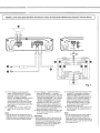
CONNECTIONS (Fig. 2 - Fig. 3)
Before making connections, be sure to turn the power off to all
audio components. Connect the battery lead from the amp directly
to the positive (+) terminal of the vehicle's battery with appropriate
in-line vehicle's fuse (see Battery Lead section). Do not connect
this lead to the vehicle's fuse block.
To prevent external noise from entering the audio system.
• Locate the unit and route the leads at least 10 em (3-15/16")
away from the car harness.
• Keep the battery power leads as far away from other leads as
possible.
• Connect the ground lead securely to a bare metal spot
(remove any paint or grease if necessary) of the car chassis.
• If you add an optional noise suppressor, connect it as far away
from the unit as possible. Your Alpine dealer carries various
noise suppressors, contact them for further information.
• Your Alpine dealer knows best about noise prevention
measures so consult your dealer for further information.
0
Speaker Output Terminals
The MRV-M250 has one set of speaker outputs. Be sure to
observe correct speaker output connections and polarity in
relation to the other speakers in the system. Connect the positive
output to the positive speaker terminal and the negative to
negative. Do not connect the speaker(-) terminal to the vehicle's
chassis.
8
Speaker Level Input Connector
These input leads are for use with head units not equipped with
preamp outputs. When not using the RCA Line Input connectors,
you should connect these wires to the speaker output leads of
your head unit. The MRV-M250 accepts input from high power or
standard power head units.
NOTES:
• Use either RCA line level or speaker level inputs. Do not
connect both at the same time.
• For the "Speaker Level Input System" setting, connecting the
Remote Turn-On Lead is not required due to the "REMOTE
SENSING" function of this product. However, the "REMOTE
SENSING" function may not work depending on the signal
source connected. In such a case, connect the Remote Turn-On
Lead to an incoming power supply cord (accessory power) in
the ACC position.
Ci) Speaker Input Leads
These leads are input leads for use with head units not equipped
with preamp outputs. When not using the RCA Line Input
connectors, you should connect these wires to the speaker output
leads of your head unit. The MRV-M250 accepts input from high
power or standard power head units.
0
Front Left Speaker (White(+))
NOTES:
• Do not connect speaker leads together or to chassis ground.
• The input is stereo but the output is monaural.
• Reversing subwoofer polarity may be desirable in some
installations for optimum bass performance.
G) Front Left Speaker (White/Black(-))
8
G) Rear Left Speaker (Green (+))
Fuse: 30A
• USE THE CORRECT AMPERE RATING WHEN REPLACING
FUSES.
Failure to do so may result in fire or electric shock.
4D
c&
CD
CD
Front Right Speaker (Gray(+))
Front Right Speaker (Gray/Black(-))
Rear Left Speaker (Green/Black(-))
Rear Right Speaker (Violet (+))
f) Power Supply Terminal
~ Rear Right Speaker (Violet/Black (-))
0
4fJ
Battery Lead (Sold Separately)
Be sure to add an in-line fuse with the battery lead as close as ...
possible to the battery's positive (+) terminal. This fuse will protect
your vehicle's electrical system in case of a short circuit. Consult
the table below for appropriate fuse value and minimum wire
gauge requirement.
• 30 amp fuse, 8AWG/8mm 2
0
Remote Turn-On Lead (Sold Separately)
Connect this lead to the remote turn-on (positive trigger, (+)
12V only) lead of your head unit. If a remote turn-on lead is
not available, see "Connection Checklist (Fig. 5)" section for
alternative method.
NOTE:
• If using speaker input level signal from the head unit, remote
turn-on lead connection is not necessary due to automatic
signal detection.
0
Ground Lead (Sold Separately)
Connect this lead securely to a clean, bare metal spot on the
vehicle's chassis. Verify this point to be a true ground by checking
for continuity between that point and the negative(-) terminal of
the vehicle's battery. Ground all your audio components to the
same point on the chassis to prevent ground loops while keeping
wire length as short as possible.
Minimum required wire gauge for this connection is as follows:
• 8AWG/8mm 2
RCA Input Jacks
Connect these jacks to the line out leads on your head unit using
RCA extension cables (sold separately). Be sure to observe
correct channel connections; Left to Left and Right to Right.
NOTE:
• Use either RCA line level or speaker level inputs. Do not
connect both at the same time.
G) Remote Bass Control (Option)
Connect the Remote Bass Control Unit (sold separately) to adjust
the output level remotely. This is not to replace appropriate gain
level setting between the amplifier and head unit.
+ About Power supply wires (Fig. 3)
&cAUTION
If the length of the power and ground cables exceed 1m, or if you
connect more than one amplifier, a distribution block should be
used. See below for wire gauge recommendations for distribution
block connection to battery and ground (depends upon wire
length necessary):
• 4AWG(21 mm 2 ) or 2AWG(33mm 2 )
Ensure that you install a correctly-rated in-line fuse on the power
cable near the battery positive post.
r--I
- - - -1- -.....·~~~....---.....::1 .. - - - -
SPEAKER OUTPUT
1
!~!
I
FUSE
1
I
0
II
-----1
POWER SUPPLY
1
!lif~!
:o~: ~ __.
~~J
~
__
1
1-- ·~ · - - __ _.
_,I
*
0
-~~~~~~~~~
~======_~~-~~~·~=-=_=_==___!~_~
CH-1
2
3
4
,,;~~~,0 ·~
~-.
a
·o· - .
I
I
~1~ /f.:~a ::H-HU
LE;;~ ~~T :I @::H-2(RJ
I
(L) (R)..
(L) (R)
MRV-M 50
~I~
I
I
I
INPUT
I
I
~ [Q]I
~~ :~• ~'
:
:
I
I
:____
,1JJi:L _.:
GAIN
LP FILTER
BASS EQ
*Be sure to add an in-line fuse with the battery lead as close as possible to
the battery's positive ( +) terminal./
Veillez a ajouter un fusible en ligne au fil de la batterie aussi pres que
possible de la borne positive ( +) de la batterie./
No olvide aiiadir un fusible en lfnea con el cable de la bater{a tan cerca
como sea posible del terminal positivo ( +) de la bater{a.
Fig. 2
1m (Max.)/
1 metre (Max.)/
1 m (max.)
4AWG or 2AWG I 21 mm 2 or 33mm 2/
4AWG ou 2AWG I 21 mm 2 ou 33mm 2/
4AWG o 2AWG I 21 mm 2 o 33mm 2
I
•IIIII
.. :
I
I
I
I
I
I
r-----------:• 8AWG/ :
2
BATTERY
I==B=m=m=~
MRV-M250
To car battery/
Vers Ia batterie
du vehicule/
A Ia baterfa del
cache
8AWG/
~Bm=m===1
2
GROUND
I
I
I
I
I
I
I
I
I
•IIIII
Distribution block/
Repartiteu r/
Bloque de distribuci6n
...
I
I
1m (Max.)/
1 metre (Max.)/
1 m (max.)
Fig. 3
========~~i=l~
.~. ·:<~- ~. M
IFil
GAIN
LP FILTER
BASS EQ
REMOTE
BASS
CONTROL
Fig. 4
CD
MRV-M250
®
I---I
I
0 I
I
I
I
----I
®
®
(®
(j)
@
Fig. 5
SWITCH SETTINGS (Fig. 4)
NOTE:
• Before switching each Selector Switch, turn off the power and
insert a small screwdriver, etc., perpendicularly to the Switch.
f) Crossover Frequency Adjustment Knob (LP FILTER)
G>
~ Bass EQ Adjustment Knob
Add a 50 Hz bass boost up to + 12 dB to tune your bass response.
Input Gain Adjustment Control
Set the MRV-M250 input gain to the minimum position. Using a
dynamic CD as a source, increase the head unit volume until the
output distorts. Then, reduce the volume 1 step (or until the output
is no longer distorted). Now, increase the amplifier gain until the
sound from the speakers becomes distorted. Reduce the gain
slightly so the sound is no longer distorted to achieve the optimum
gain setting.
Use this control to adjust the crossover frequency between 50 to
400Hz.
m Power Indicator
Indication color
Green
Red (blinking)
Red
Status
Solution
Amplifier circuit is normal.
Operating temperature is high.
Decrease the vehicle's interior temperature to a normal level. The
indicator color changes to green.
Amplifier circuit is abnormal. An
electrical short has occurred, or
supply current is too high.
Turn off the power supply and eliminate the cause. Then turn on the unit
and verify that the indicator color has changed to green. If it remains red,
turn off the unit and consult your dealer.
Operating temperature is too high.
Decrease the vehicle's interior temperature to a normal level. The
indicator color changes to red (blinking).
Power supply voltage is too high.
Use the correct power supply voltage. The indicator color changes to
green.
CONNECTION CHECKLIST (Fig.5)
Please check your head unit for the conditions listed below:
(Fig. 5)
a. The head unit does not have a remote turn-on or power
antenna lead.
b. The head unifs power antenna lead is activated only when
the radio is on (turns off in the tape or CD Mode).
c. The head unifs power antenna lead is logic level output(+)
5V, negative trigger (grounding type), or cannot sustain (+)
12V when connected to other equipment in addition to the
vehicle's power antenna.
If any of the above conditions exist, the remote turn-on lead
of your MRV-M250 must be connected to a switched power
source (ignition) in the vehicle. Be sure to use a 3A fuse as
close as possible to this ignition tap. Using this connection
method, the MRV-M250 will turn on and stay on as long as
the ignition switch is on.
If this is objectionable, a SPST (Single Pole, Single Throw) switch,
in addition to the 3A fuse mentioned above, may be installed inline on the MRV-M250 turn-on lead. This switch will then be used
to turn on (and off) the MRV-M250. Therefore, the switch should
be mounted so that is accessible by the driver. Make sure the
switch is turned off when the vehicle is not running. Otherwise, the
amplifier will remain on and drain the battery.
CD Blue/White
® Power Antenna
@ Remote Turn-On Lead
@ To other Alpine components' Remote Turn-On Leads
® SPST Switch (optional)
® Fuse (3A)
(j) As close as possible to the vehicle's ignition tap
® Ignition Source
SYSTEM DIAGRAMS/DIAGRAMMES DU SYSTEMEIDIAGRAMAS DEL SISTEMA
[English]
@) Subwoofer (sold separately)
fll
Typical System Connections/Connexions Typiques du Systeme/Conexiones Tfpicas del Sistema
RCA Extension Cable (sold separately)
@I Head Unit, etc.
~ Y-Adaptor (sold separately)
[Fran~ais]
@) Haut-parleur de sous-graves (vendu separement)
fJ) Cable d'extension RCA (vendu separement)
@I Unite principals, etc.
~ Adaptateur en forme de "Y , (vendu separement)
[Espaiiol]
@) Altavoz de subgraves (vendido separadamente)
fll
Prolongador electrico RCA (vendido separadamente)
@I Unidad principal, etc.
~ Adaptador en forma de "Y" (vendido separadamente)
Fig.6
Speaker Level Input System/Systeme d'entree de niveau de haut-parleur/Sistema de entrada de nivel de altavoz
Cl!)
0 White
0 Violet/Black
0 White/Black
0 Violet
0 Gray
0 Green/Black
0 Gray/Black
0 Green
mm
• • ••
G)
~
~
m
•• • •
FR 0 Gray/Black
RL0 Green
FR0 Gray
RL 0 Green/Black
FL 0 White/Black
RR0 Violet
FL 0 White
RR 0 Violet/Black
Fig. 7
*1 For the "Speaker Level Input System"
setting, connecting the Remote Turn-On
Lead is not required due to the "REMOTE
SENSING" function of this product.
However, the "REMOTE SENSING" function
may not work depending on the signal
source connected. In such a case, connect
the Remote Turn-On Lead to an incoming
power supply cord (accessory power) in the
ACC position.
*2 Use either RCA line level or speaker level
inputs. Do not connect both at the same
time.
*1 Pour le reglage « Systeme d'entree de
niveau de haut-parleur », il n'est pas
necessaire de raccorder le fil de mise sous
tension telecommandee grace a Ia fonction
« REVElL AUTOMATIQUE » de ce produit.
II est neanmoins possible que Ia fonction
« REVElL AUTOMATIQUE » ne soit pas
disponible en fonction de Ia source du
signal. Connecter alors le conducteur de
mise sous tension telecommandee un
cordon d'alimentation entrant (alimentation
des accessoires) en position ACC.
*2 Utiliser les entrees de niveau de ligne RCA
ou de niveau de haut-parleur. Jamais les
connecter a Ia fois.
a
NOTE:
• Only left/right channel speaker level input is
required. However, all speaker input leads (FU REMARQUE:
FR/RURR) may be connected to prevent zero • Seule I' entree de niveau de haut-parleur du
canal gauche/droit est requise. Vous pouvez
output when the head unit fader is adjusted.
neanmoins raccorder tousles fils d'entree
de haut-parleur (FUFRIRURR) pour eviter
!'absence de signaux lors du reglage de
l'equilibreur de l'unite principale.
*1 Para el ajuste "Sistema de entrada de nivel
de altavoz", no es necesario co nectar el
cable de encendido debido a Ia funci6n
"SENSOR REMOTO" de este producto. No
obstante, Ia funci6n "SENSOR REMOTO"
podrfa no funcionar segun Ia fuente de Ia
senal conectada. En ese caso, conecte
el cable de encendido remote a un cable
de alimentaci6n entrante (alimentaci6n
adicional) en Ia posicion ACC.
*2 Utilice las entradas de nivel de altavoz o de
nivel de lfnea RCA. No conecte las dos al
mismo tiempo.
NOTA:
• Solo se requiere entrada de nivel de altavoz
de canal izquierdo/derecho. No obstante,
todos los cables de entrada de altavoz (FU
FR/RURR) se pueden conectar para evitar Ia
ausencia de entrada cuando se ajuste el fader
de Ia unidad principal.
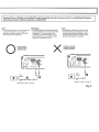
Important Tips on Bridging an Amplifier/Conseils importants Iars de Ia mise en pont d'un amplificateur/Consejos
importantes cuando conecte en puente un amplificador
REMARQUE:
• Le systeme presente une faible puissance
en cas d'utilisation d'un seul canal d'entree.
~adaptateur Y n'est pas requis en cas
d'utilisation d'une sortie de ligne ou d'un
couple stereo/mono pour piloter les deux
entrees de l'amplificateur ponte.
NOTE:
• Low output will result if only one channel input
is used. TheY-adapter is not required if a
stereo/mono pair line output is used to drive
both inputs of the bridged amp.
0
X
Proper connection/
Connexion correcte/
Conexi6n correcta
POWERO
(PROTECT)
Ill
CH-1
2
3
4
•
•
•
•
NOTA:
• Se obtendran salidas bajas si s61o se utiliza
una entrada de canal. El adaptador-Y no es
necesario si se utiliza una pareja de salida
en lfnea estereo/mono para conducir ambas
entradas del amplificador puenteado.
Improper connection/
Connexion incorrecte/
Conexi6n incorrecta
D
.'":;;;~I i@ : : :
M~250 ~t=·===
~~J~
(L)
(One signal I Un signal I Una seiial)
~J~
(L)
(One signal I Un signal I Una seiial)
Fig. 8
Thank you for choosing Alpine for your car audio equipment needs. Our goal is to
produce the best audio/video/navigation products in the world and hope your
expectations are met.
Please take a moment to protect your purchase by registering your product now at
the following address: www.alpine-usa.com/registration. You will be informed of
product and software updates (if applicable), special promotions, and news about
Alpine. Also, by registering your product, you will automatically be entered for a
chance to win various prizes such as gift cards, Alpine products, and/or a complete
system.
We look forward to continue serving you in the future.
Sincerely,
The Alpine Team
French
Spanish
Nous vous remercions d'avoir porte votre choix sur un
equipement audio automobile Alpine. Notre principal
objectif est de fabriquer les meilleurs produits audio,
video et de navigation au monde afin de repondre aux
exigences de nos clients.
Gracias por elegir Alpine para las necesidades de
equipamiento de audio de su vehiculo. Nuestro
objetivo es fabricar los mejores productos de audio/
vfdeo/navegaci6n del mundo y esperamos poder
cumplir sus expectativas.
Veuillez prendre quelques instants pour securiser
votre achat en enregistrant votre produit a l'adresse
suivante : www.alpine-usa.com/registration. Vous
serez tenu informe des nouveaux produits, des mises
a jour logicielles (le cas echeant), des promotions
speciales et des informations concernant Alpine.
L'enregistrement de votre produit vous donne par
ailleurs Ia possibilite de gagner des dizaines de
cadeaux, tels que cheques-cadeaux et articles Alpine,
ainsi qu'un systeme complet.
Dedique unos mementos a proteger su compra:
registre ahora su producto en Ia siguiente direcci6n:
www.alpine-usa.com/registration. Recibira
informacion de novedades sobre el producto y
actualizaciones de software (si se producen),
promociones especiales y noticias de ultima hora de
Alpine. Asimismo, si registra su producto, entrara
automaticamente en el sorteo de diversos premios,
como tarjetas de regale, productos de Alpine y/o un
sistema complete.
Nous esperons que nos produits vous donneront
entierement satisfaction.
Esperamos poder seguir ofreciendole el mejor
servicio en el futuro.
Cordialement,
Atentamente,
L'equipe Alpine
El equipo de Alpine
PART NO. 68-21627Z36-A
M354415301 0
~LPINE:a
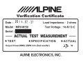
Verification Certificate
20 1 4 . 02 · 21
Date :
Model : MRV-M250
)-
',
)
_/·
,... '
.~-~-
~··.-
, -·
'
Load Impedance: 2 ohms
Test Voltage : 14.4V D.C
Serial :
-
ACTUAL TEST MEASUREMENT -
•TEST
•SPECIFICATION
•ACTUAL
Output Power(RMS) 250W min {Sub woofer)
ALPINE ELECTRONICS, INC.
.-
##HILPINE®
GARANTIE LIMITEE
Fideles a leur engagement de ne fournir que des produits de qualite, ALPINE ELECTRONIQUE DE L'AMERIQUE, INC. et
ALPINE ELECTRONIQUE DU CANADA, INC. (Alpine) sont heureuses de vous offrir cette garantie. Nous vous suggerons dele
lire attentivement et en entier. Si vous avez Ia moindre question, veuillez contacter l'un de nos concessionnaires ou appeler
directement Alpine aux numeros listes ci-dessous.
®
Cette garantie est en vigueur pendant un an a partir de Ia date
du premier achat du client.
Vous devez donner une description detaillee des
problemes qui sont a l'origine de votre demande de
reparation.
@ Vous devez joindre Ia preuve de votre achat du produit.
@ Vous devez emballer soigneusement le produit pour eviter
tout dommage durant son transport. Pour eviter Ia perte
de l'envoi, il est conseille de choisir un transporteur qui
propose un service de suivi des envois.
ePERSONNES PROTEGEES PAR LA GARANTIE
eUMITATION DES GARANTIES TACITES
Seull'acheteur original du produit, s'il resisde aux Etats-Unis,
a Porto Rico ou au Canada, peut se prevaloir de Ia garantie.
LA DUREE DE TOUTES LES GARANTIES TACITES, Y
COMPRIS LA GARANTIE D'ADAPTATION A L'UTILISATION
ET LA GARANTIE DE QUALITE LOY ALE ET MARCHANDE,
EST LIMITEE A CELLE DE LA GARANTIE EXPRESSE
DETERMINEE CI-DESSUS. PERSONNE N'EST AUTORISE
A ENGAGER AUTREMENT LA RESPONSABILITE D'ALPINE
EN VERTU DE LA VENTE D'UN PRODUIT.
ePRODUITS COUVERTS PAR LA GARANTIE
Cette garantie couvre les produits audio de voiture et les
accessoires connexes ("le produit"). Ellene couvre les
produits que dans le pays ou ils ont ete achetes.
eDUREE DE LA GARANTIE
eCE QUI EST COUVERT
Cette garantie couvre tous les defauts de materiaux et de
fabrication (pieces et main d'oouvre) du produit.
eCE QUI N'EST PAS COUVERT
Cette garantie ne couvre pas ce qui suit:
Les dommages survenus durant le transport des produits
renvoyes a Alpine pour etre repares (les reclamations
doivent etre adressees au transporteur);
® Les degats provoques par un accident ou une mauvaise
utilisation, y compris des bobines acoustiques grillees
suite a une surexcitation des enceintes (augmentation
du niveau de l'amplificateur jusqu'a atteindre un effet de
distorsion ou d'ecretage), une defaillance mecanique
des enceintes (perforations, dechirures ou fentes),
panneaux LCD fissures ou endommages, disques durs
endommages ou ayant subi une chute.
@ Tout degat provoque par negligence, usage inapproprie,
mauvaise utilisation ou par le non-respect des
instructions indiquees dans le manuel de l'utilisateur.
@ Les dommages dus a Ia force majeure, notamment aux
tremblements de terre, au feu, aux inondations, aux
tempetes ou aux autres cataclysmes naturels;
Les frais ou les depenses relatifs a l'enlevement ou a Ia
reinstallation du produit;
® Les services rendus par une personne, physique ou
morale non autorisee;
® Les produits dont le numero de serie a ete efface, modifie
ou retire;
(J) Les produits qui ont ete adaptes ou modifies sans le
consentement d'Aipine;
® Les produits qui ne sont pas distribues par Alpine aux
Etats-Unis, a Porto Rico ou au Canada;
® Les produits qui n'ont pas ete achetes par l'entremise d'un
concessionnaire Alpine autorise;
CD
eCOMMENT SE PREVALOIR DE LA GARANTIE
CD
II vous taut remettre le produit necessitant des reparations
a un centre de service autorise Alpine ou a Alpine meme et
en assumer les frais de transport. Alpine a le choix entre
reparer le produit ou le remplacer par un produit neuf ou
revise, le tout sans frais pour vous. Si les reparations sont
couvertes par Ia garantie et si le produit a ete envoye a un
centre de service Alpine ou a Alpine, le paiement des frais
de reexpedition du produit incombe Alpine.
eEXCLUSIONS DE LA GARANTIE
ALPINE STIPULE EXPRESSEMENT QU'ELLE N'EST PAS
RESPONSABLE DES DOMMAGES-INTERETS ET
DOMMAGES INDIRECTS PROVOQUES PAR LE PRODUIT.
LES DOMMAGES-INTERETS SONT LES FRAIS DE
TRANSPORT DU PRODUIT VERS UN CENTRE DE
SERVICE ALPINE, LA PEATE DE TEMPS DE L'ACHETEUR
ORIGINAL, LA PERTE D'UTILISATION DU PRODUIT, LES
BILLETS D'AUTOBUS, LA LOCATION DE VOITURES ET
TOUS LES AUTRES FRAIS LIES A LA GARDE DU
PRODUIT.
LES DOMMAGES INDIRECTS SONT LES FRAIS DE
REPARATION OU DE REMPLACEMENT D'AUTRES BIENS
ENDOMMAGES SUITE AU MAUVAIS FONCTIONNEMENT
DU PRODUIT.
LES RECOURS PREVUS PAR LES PRESENTES
EXCLUENT ET REMPLACENT TOUTE AUTRE FORME DE
RECOURS.
ellEN ENTRE LA GARANTIE ET LA LOI
La garantie vous donne des droits specifiques, mais vous
pouvez aussi jouir d'autres droits, qui varient d'un etat ou
d'une province a l'autre. En outre, certains etats et certaines
provinces interdisent de limiter Ia duree des garanties tacites
ou d'exclure les dommages accessoires ou indirects. Dans ce
cas, les limites et les exclusions de Ia garantie peuvent ne pas
s'appliquer a vous.
eCLAUSE APPLICABLE AU CANADA SEULEMENT
Pour que Ia garantie soit valable, il taut qu'un centre
d'installation autorise ait installe le systeme audio pour l'auto
dans votre vehicule et qu'il ait ensuite appose son cachet sur
Ia garantie.
eNUMEROS D'APPEL DU SERVICE
ALA CLIENTELE
Si vous avez besoin de nos services, veuillez appeler Alpine
aux numeros ci-dessous pour le centre de service autorise
Alpine le plus proche.
AUDIO DE VOITURE
NAVIGATION
1-800-ALPINE-1 (1-800-257-4631)
1-888-NAV-HELP (1-888-628-4357)
Ou visitez notre site Web a l'adresse http://www.alpine-usa.com
ALPINE ELECTRONIQUE DE L'AMERIQUE, INC., 19145 Gramercy Place, Torrance, California 90501, U.S.A.
ALPINE ELECTRONIQUE DU CANADA, INC., 777 Supertest Road, Toronto, Ontario M3J 2M9, Canada
N'envoyez aucun produit aces adresses.
Appelez notre numero gratuit ou visitez notre site Web si vous recherchez un centre de service.
ff#MLPIN E®
LIMITED WARRANTY
ALPINE ELECTRONICS OF AMERICA, INC. AND ALPINE OF CANADA INC. ("Alpine"), are dedicated to quality
craftsmanship and are pleased to offer this Warranty. We suggest that you read it thoroughly. Should you have any
questions, please contact your Dealer or contact Alpine at one of the telephone numbers listed below.
ePRODUCTS COVERED:
@ You must supply proof of your purchase of the product.
This Warranty covers Car Audio Products and Related
Accessories ("the product"). Products purchased in the
Canada are covered only in the Canada. Products
purchased in the U.S.A. are covered only in the U.S.A.
@You must package the product securely to avoid
damage during shipment. To prevent lost packages it is
recommended to use a carrier that provides a tracking
seNice.
eLENGTH OF WARRANTY:
eHOW WE LIMIT IMPLIED WARRANTIES:
This Warranty is in effect for one year from the date of the
first consumer purchase.
This Warranty only covers the original purchaser of the
product, who must reside in the United States, Puerto Rico
or Canada.
ANY IMPLIED WARRANTIES INCLUDING FITNESS FOR
USE AND MERCHANTABILITY ARE LIMITED IN
DURATION TO THE PERIOD OF THE EXPRESS
WARRANTY SET FORTH ABOVE AND NO PERSON IS
AUTHORIZED TO ASSUME FOR ALPINE ANY OTHER
LIABILITY IN CONNECTION WITH THE SALE OF THE
PRODUCT.
eWHAT IS COVERED:
eHOW WE EXCLUDE CERTAIN DAMAGES:
eWHO IS COVERED:
This Warranty covers defects in materials or workmanship
(parts and labor) in the product.
eWHAT IS NOT COVERED:
This Warranty does not cover the following:
G) Damage occurring during shipment of the product to
Alpine for repair (claims must be presented to the
carrier).
® Damage caused by accident or abuse, including burned
voice coils caused by over-driving the speaker (amplifier
level is turned up and driven into distortion or clipping).
Speaker mechanical failure (e.g. punctures, tears or
rips). Cracked or damaged LCD panels. Dropped or
damaged hard drives.
@ Damage caused by negligence, misuse, improper
operation or failure to follow instructions contained in the
Owner's manual.
@ Damage caused by act of God, including without
limitation, earthquake, fire, flood, storms or other acts of
nature.
Any cost or expense related to the removal or
reinstallation of the product.
® SeNice performed by an unauthorized person, company
or association.
®Any product which has the serial number defaced,
altered or removed.
(j) Any product which has been adjusted, altered or
modified without Alpine's consent.
® Any product not distributed by Alpine within the United
States, Puerto Rico or Canada.
® Any product not purchased from an Authorized Alpine
Dealer.
ALPINE EXPRESSLY DISCLAIMS LIABILITY FOR
INCIDENTAL AND CONSEQUENTIAL DAMAGES
CAUSED BY THE PRODUCT. THE TERM "INCIDENTAL
DAMAGES" REFERS TO EXPENSES OF
TRANSPORTING THE PRODUCT TO THE ALPINE
SERVICE CENTER, LOSS OF THE ORIGINAL
PURCHASER'S TIME, LOSS OF THE USE OF THE
PRODUCT, BUS FARES, CAR RENTALS OR OTHERS
COSTS RELATING TO THE CARE AND CUSTODY OF
THE PRODUCT. THE TERM "CONSEQUENTIAL
DAMAGES" REFERS TO THE COST OF REPAIRING OR
REPLACING OTHER PROPERTY WHICH IS DAMAGED
WHEN THIS PRODUCT DOES NOT WORK PROPERLY.
THE REMEDIES PROVIDED UNDER THIS WARRANTY
ARE EXCLUSIVE AND IN LIEU OF ALL OTHERS.
eHOW STATE/PROVINCIAL LAW RELATES TO THE
WARRANTY:
This Warranty gives you specific legal rights, and you may
also have other rights which vary from state to state and
province to province. In addition, some states/provinces do
not allow limitations on how long an implied warranty lasts,
and some do not allow the exclusion or limitation of
incidental or consequential damages. Accordingly,
limitations as to these matters contained herein may not
apply to you.
eiN CANADA ONLY:
This Warranty is not valid unless your Alpine car audio
product has been installed in your vehicle by an Authorized
Installation Center, and this warranty stamped upon
installation by the installation center.
eHOW TO OBTAIN WARRANTY SERVICE:
eHOW TO CONTACT CUSTOMER SERVICE:
G) You are responsible ·tor delivery of the product to an
Should the product require seNice, please call the following
number for your nearest Authorized Alpine SeNice Center.
®
Authorized Alpine SeNice Center or Alpine for repair
and for payment of any initial shipping charges. Alpine
will, at its option, repair or replace the product with a
new or reconditioned product without charge. If the
repairs are covered by the warranty, and if the product
was shipped to an Authorized Alpine SeNice Center or
Alpine, Alpine will pay the return shipping charges.
You should provide a detailed description of the
problem(s) for which seNice is required.
CAR AUDIO 1-800-ALPINE-1 (1-800-257-4631)
NAVIGATION 1-888-NAV-HELP (1-888-628-4357)
Or visit our website at; http://www.alpine-usa.com
ALPINE ELECTRONICS OF AMERICA, INC., 19145 Gramercy Place, Torrance, California 90501, U.S.A.
ALPINE ELECTRONICS OF CANADA, INC., 777 Supertest Road, Toronto, Ontario M3J 2M9, Canada
Do not send products to these addresses.
Call the toll free telephone number or visit the website to locate a seNice center.
68-00493Z72-A (Y)
M3544091 010