1
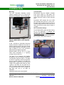
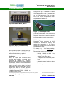
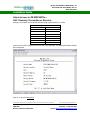
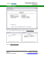
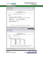
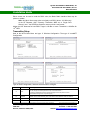
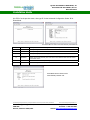
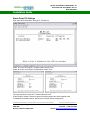
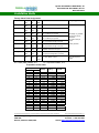
System Part Number: 900-0782-81, -91
Document P/N: 551-0782-81, Rev C1
December 2014
Installation Guide
RMAS-120-81 and -91 UHF Radio Extensions
Introduction
900 MHz version:
The RMAS-120-81 and -91 adds a UHF
Radio Link to the RMAS-120 Remote
Monitor and Alarm System. The UHF Radio
Link provides an alternative transmission
channel for the RF Repeater Alarm data that
is otherwise carried by added modulation to
the repeated microwave carriers.
System Part Number:
RMAS-120-01 PN:
UHF Telemetry Tx PN:
UHF Telemetry Rx PN:
The -81 UHF Radio operates in the 902 ~
928 MHz band while the -91 UHF Radio
operates in the 2400 MHz band. Both use
frequency hopping spread spectrum coding.
These are license free bands under US-FCC
Part 15.247 rules and Canadian ISC
document RSS-210. The duplex radios are
GE MDS NETioB-900 and NETioB-2400
with Expansion Modules.
The RMAS-120-01 Alarm Transmitter unit’s
local alarm points are routed to the MDS
radio link equipment. Eight (8) alarm points
are transported in this RMAS-120-81
configuration. Other configurations can
transport 14 or 20 alarm points. Contact
PESi for availability.
900-0782-81
090-0781-01
090-0783-81
090-0784-81
2400 MHz version
System Part Number:
RMAS-120-01 PN:
UHF Telemetry Tx PN:
UHF Telemetry Rx PN:
900-0782-91
090-0781-01
090-0783-91
090-0784-91
UHF Telemetry and RMAS
Transmitter Assembly
The 090-0783-81, -91 UHF Telemetry
Transmitter Assembly and 090-0781-01
RMAS-120 Alarm Transmitter Assembly are
shown in Figure 1.
Additionally, the battery temperature voltage
is transported on an analog voltage to
instrumentation current loop channel.
Alarms are sent from the RF Repeater site
to the RMAS-120-81, -91 UHF Telemetry
Receiver located at the associated
microwave radio terminal end.
The duplex radio link is configured with one
control channel from the Telemetry Receiver
to the RF Repeater site. This control
channel provides a closure at the repeater
site and can be used as required. Examples
are: GenSet start and equipment shutdown.
Figure 1, RMAS UHF Transmitter Assy
The radio link equipment is normally
configured at the PESi factory for the
particular field application. See the factory
test data sheet for more details.
Peninsula Engineering Solutions may change specifications as necessary to meet industry requirements.
Peninsula Engineering Solutions, inc.
POB 1095
Danville, California 94526, USA
© 2014 Peninsula Engineering Solutions, inc.
Telephone +1 925 837-2243
Facsimile +1 925 837-2298
Internet www.peninsulaengineering.com
System Part Number: 900-0782-81, -91
Document P/N: 551-0782-81, Rev C1
December 2014
Installation Guide
Mounting
Transmit Power
The UHF Transmitter Assembly mounts
inside the repeater door or in a 19-inch rack
below the RF Repeater. The unit is 8U high.
Recommend using the 100mW, +20 dBm
lower power setting for LOS paths. The
lower power setting also reduces the DC
current load and is best for solar powered
sites.
Peninsula’s UHF antenna kits use 12 dBi
gain antennas and 3/8-inch or ½-inch coax.
At typical 50-Ft feedline plus the jumper at
the alarm equipment has 2 dB of loss. In this
case, the maximum output power setting is
+26 dBm.
UHF Transmitter Settings
The GE MDS NETio radio has been factory
set for the application. If changes are
required, see the section Admin Access to
the GE MDS NETio following or the GE
MDS NETio manual for details, 05-4457A01,
Rev D or later, PES PN 551-0790-01.
Figure 2, RMAS UHF Tx in RF Repeater
Antenna
A 902 ~ 928 MHz or 2400 MHz directional
antenna should be installed on the tower or
antenna support structure that also mounts
the microwave antennas. Normally, the UHF
path is parallel to one of the microwave
paths and Line-of-Sight is expected.
Antenna feedline can be 3/8” or ½” Foam
Filled Coax terminated in a Type-N(f)
connector at the radio end.
The gain of the antenna and feedline
combination may be limited by regulations.
The 900 MHz maximum EIRP is +36 dBm
by US-FCC regulations. With the transmitter
set at low power, 100mW or +20 dBm, the
antenna gain – feeder loss must not exceed
16 dBi. If the highest power setting is used,
1-Watt or +30 dBm, the net gain limit is
6dBi. The radios transmit power may be set
in 1 dB increments from +20 to +30 dBm for
900 MHz and +20 to +27 dBm for
2400 MHz.
Figure 3, UHF Tx Antenna Cable
Lightning Arrestors are recommended.
Peninsula Engineering Solutions may change specifications as necessary to meet industry requirements.
Peninsula Engineering Solutions, inc.
POB 1095
Danville, California 94526, USA
© 2014 Peninsula Engineering Solutions, inc.
Telephone +1 925 837-2243
Facsimile +1 925 837-2298
Internet www.peninsulaengineering.com
System Part Number: 900-0782-81, -91
Document P/N: 551-0782-81, Rev C1
December 2014
Installation Guide
Antenna Kit
Connections
If an antenna kit from PESi was supplied,
install the included lightning arrestor at the
bottom of the RF Repeater enclosure. Punch
or drill a 5/8-inch diameter hole for the Type
N(f) connector and mounting bracket.
Locate the hole toward the left side as
viewed from the front. Be sure the internal
antenna cable jumper will reach the hole
location. Follow the installation directions
supplied with the lightning arrestor.
Figure 4, UHF Tx
Lightning Arrestor,
at bottom of
RF Repeater
enclosure
UHF & RMAS Tx Assy
Connect to:
UHF Antenna Jumper,
Type-N(m), Fig. 3
UHF Antenna feedline,
Type-N(f)
(Lightning Arrestor)
Door on Screw Terminal
Block
Wht/Blu/Blk
Wht/Blk/Slt
Repeater Door Switch
cable, (no polarity).
Wht/Grn/Blk
Wht/Yel/Blk
RF Power Monitor F1
F1 BNC coax cable
RF Power Monitor F2
F2 BNC coax cable
J1 Adapter Cable, 20 Pin
Repeater Alarm Cable, P1
Waveguide Pressure
Sensor
RMAS TX Internal TB-1
IN - 5
IN - 4
Waveguide Pressure
Sensor Cable
(no polarity)
Green
Blue
Temperature Sensor
RMAS TX Internal TB-1
C–3
B–2
A–1
Temperature Sensor
Cable
Yellow - C
White - B
Black - A
Caution!
Once battery is connected, the UHF Transmitter will
begin transmitting.
Battery A+ 12 VDC or
8.5 VDC
Battery B+ 12 VDC or
8.5 VDC
DC Power Cable with
3-pin plug P1 is attached
to the RMAS Tx TB-1 and
connects to the RF
Repeater Aux DC
connector located on the
repeater door.
12V repeaters = P6
24V repeaters = P7
Figure 5, Screw Terminal Block TB-1,
UHF Tx with P1 DC Power Cable
Note the PWR and LINK LEDs on the MDS
Transmitter. Both should be ON.
Peninsula Engineering Solutions may change specifications as necessary to meet industry requirements.
Peninsula Engineering Solutions, inc.
POB 1095
Danville, California 94526, USA
© 2014 Peninsula Engineering Solutions, inc.
Telephone +1 925 837-2243
Facsimile +1 925 837-2298
Internet www.peninsulaengineering.com
System Part Number: 900-0782-81, -91
Document P/N: 551-0782-81, Rev C1
December 2014
Installation Guide
Turn on the RMAS-120 Alarm Transmitter
and verify operation by pressing the LED
Switch. All alarm LEDs should light briefly
(lamp test) and then only the actual alarms
will remain ON.
Confirm the RMAS-120 Alarm Transmitter
OPTO COPLR jumper is set to ENB.
UHF Receiver Settings
The GE MDS NETio radio has been factory
set for the application. If changes are
required, see the section Admin Access to
the GE MDS NETio following, or the GE
MDS NETio manual for details, 05-4457A01,
Rev D or later, PES PN 551-0790-01.
RMAS-120-81 UHF Telemetry
Receiver
The 090-0784-81, -91 UHF
Assembly is shown in Figure 6.
Receiver
Figure 6, UHF Telemetry Receiver Assy
Mounting
The UHF Receiver Assembly mounts in a
19-inch rack. The unit is 2U high with a
5-inch front projection.
Antenna
A directional antenna should be installed on
the tower or antenna support structure that
also mounts the microwave antennas.
Normally, the UHF path is parallel to one of
the microwave paths and Line-of-Sight is
expected.
Antenna feedline can be 3/8” or ½” Foam
Filled Coax terminated in a Type-N(m)
connector at the radio end.
Figure 7, Rx MDS Modules
Connections
UHF Receiver Assy
Connect to:
UHF Antenna Port,
Type-N(f)
UHF Antenna feedline,
Type-N(m)
Caution!
Once battery is connected, the UHF Receiver will
begin
operating.
This
unit
includes
a
UHF transmitter.
20-60 VDC IN, GND, +, Isolated Input
Fuse at 1 Amp
For Negative Battery,
jumper the (+) terminal to
GND and connect to Rack
Ground.
Connect fused (-) Battery
to the (-) terminal.
The gain of the antenna and feedline
combination may be limited by regulations.
The maximum EIRP is +36 dBm. With the
transmitter set at low power, 100mW or
+20 dBm, the antenna gain – feeder loss
must not exceed 16 dBi. If the high power
setting is used, 1-Watt or +30 dBm, the net
gain limit is 6 dBi.
Lightning Arrestor is recommended.
Figure 8, UHF Receiver, Rear
Peninsula Engineering Solutions may change specifications as necessary to meet industry requirements.
Peninsula Engineering Solutions, inc.
POB 1095
Danville, California 94526, USA
© 2014 Peninsula Engineering Solutions, inc.
Telephone +1 925 837-2243
Facsimile +1 925 837-2298
Internet www.peninsulaengineering.com
System Part Number: 900-0782-81, -91
Document P/N: 551-0782-81, Rev C1
December 2014
Installation Guide
Performance can be verified at the RMAS
UHF Telemetry Transmitter by connecting a
computer terminal to COM 1 serial data port
on the MDS base module. This port is an
RJ-45 and requires an adapter to 9-pin
subminiature female. The adapter is
supplied with the RMAS unit.
Figure 9, Terminal Block, UHF Rx
Figure 11, COM Adapter Cable
The COM Port provides access to the MDS
Base (radio) module and to the attached
expansion module. The MDS modules are
interconnected by a module to module bus.
MDS Settings
Figure 10, UHF Rx, J1 Alarm Points,
UHF Antenna Port
Peninsula’s factory configures the MDS
modules to communicate properly and
assigns the alarm points. All the factory
settings are recorded in the Test Data Sheet
supplied with the order.
To change any of the factory settings,
please see the next section Admin Access.
Note the indicator LED on the UHF Receiver
Front Panel. The Green POWER ON LED
will be ON when battery is applied.
Verification
Once the RMAS UHF transmitter and
receiver are installed, connected and
powered, the RMAS UHF Telemetry
Receiver should acquire the radio signal and
synchronize. Connect a computer terminal
to the COM 1 port on the receiver’s front
panel to verify receive signal level and
performance. Minimum 900 MHz receive
signal level, RSSI is -106 dBm. Minimum
2400 MHz receive signal level, RSSI is 104 dBm Recommend RSSI -95 dBm to
-60 dBm for best service.
Reasons that changes may be required:
1. Multiple RMAS or MDS links
operating nearby require network
address or unit ID to change.
2. To adjust the UHF transmitter power
level.
3. Change the owner, location or alarm
point names.
4. Module replacement.
Peninsula Engineering Solutions may change specifications as necessary to meet industry requirements.
Peninsula Engineering Solutions, inc.
POB 1095
Danville, California 94526, USA
© 2014 Peninsula Engineering Solutions, inc.
Telephone +1 925 837-2243
Facsimile +1 925 837-2298
Internet www.peninsulaengineering.com
System Part Number: 900-0782-81, -91
Document P/N: 551-0782-81, Rev C1
December 2014
Installation Guide
Admin Access to GE MDS NETio -UHF Telemetry Transmitter or Receiver
Configure a computer as a serial data terminal using HyperTerminal™ or similar.
Terminal Settings
Data Rate
19200 bps
Data bits
8
Parity
None
Stop bits
1
Flow Control
None
Terminal Emulation
VT100
Login
admin
Password
admin
Connect to the UHF Telemetry Receiver’s COM 1 port and login. The Starting Information Screen
will be displayed.
Type ‘G’ to go to the Main Menu.
Peninsula Engineering Solutions may change specifications as necessary to meet industry requirements.
Peninsula Engineering Solutions, inc.
POB 1095
Danville, California 94526, USA
© 2014 Peninsula Engineering Solutions, inc.
Telephone +1 925 837-2243
Facsimile +1 925 837-2298
Internet www.peninsulaengineering.com
System Part Number: 900-0782-81, -91
Document P/N: 551-0782-81, Rev C1
December 2014
Installation Guide
Type ‘I’ to go to the Statistics / Events Menu, then Type ‘A’ for Performance Statistics.
Type ‘G’ for entraNET Radio Statistics
Peninsula Engineering Solutions may change specifications as necessary to meet industry requirements.
Peninsula Engineering Solutions, inc.
POB 1095
Danville, California 94526, USA
© 2014 Peninsula Engineering Solutions, inc.
Telephone +1 925 837-2243
Facsimile +1 925 837-2298
Internet www.peninsulaengineering.com
System Part Number: 900-0782-81, -91
Document P/N: 551-0782-81, Rev C1
December 2014
Installation Guide
Type ‘A’ and toggle the type of report using the SPACEBAR. Stop at RSSI/Zone Statistics.
Peninsula Engineering Solutions may change specifications as necessary to meet industry requirements.
Peninsula Engineering Solutions, inc.
POB 1095
Danville, California 94526, USA
© 2014 Peninsula Engineering Solutions, inc.
Telephone +1 925 837-2243
Facsimile +1 925 837-2298
Internet www.peninsulaengineering.com
System Part Number: 900-0782-81, -91
Document P/N: 551-0782-81, Rev C1
December 2014
Installation Guide
Either screen can be used to read the RSSI value, the Basic Radio Interface Stats may be
quicker to update.
Note: this Basic Stats screen does not display real RSSI (shows -120 dBm only)
at the RF Repeater (UHF Telemetry Transmitter, MDS set to “Single Root
Remote”) end – the RSSI/Zone Statistics screen must be used instead.
Adjust the UHF antennas for best RSSI. Target is -95 dBm or more. Threshold is -106 dBm for
10-06 BER.
Transmitter Setup
Start at the NETio Main Menu and type ‘C’ Wireless Configuration. Then type ‘A’ entraNET
Configuration.
Type ‘A’ Basic Configuration, and then select the item to configure.
Selection
Item
Description
A
Unit
ID for base and associated expansion modules. Defaults to the last 4 digits of the base serial number † .
Can be changed as necessary. Must be unique on the same network.
If replacing a failed base module, recommend changing the ID to the previous unit’s ID.
This eliminates changes to far end point mapping.
B
Network
Address
All units on the same network must use the same address. Both ends of the
RMAS-120-81 UHF Telemetry Link must use the same address. Select as desired.
C
Output Power
+20 to +30 dBm in 1 dB steps.
D
Band
2400 MHz only, select A, B or C. Transmitter and Receiver must match.
Peninsula Engineering Solutions may change specifications as necessary to meet industry requirements.
Peninsula Engineering Solutions, inc.
POB 1095
Danville, California 94526, USA
© 2014 Peninsula Engineering Solutions, inc.
Telephone +1 925 837-2243
Facsimile +1 925 837-2298
Internet www.peninsulaengineering.com
System Part Number: 900-0782-81, -91
Document P/N: 551-0782-81, Rev C1
December 2014
Installation Guide
Hit <ESC> for the previous menu, then type ‘B’ for the Advanced Configuration. Select ‘B’ for
Direct Mode.
Direct Mode Menu as shown at the UHF Telemetry Transmitter end.
Selection
Item
Description – For UHF Telemetry Transmitter, RF Repeater end.
A
DEFAULT
Factory setting: Default direct state is direct mode
B
MODE
Factory setting: Enter direct mode
C
TYPE
Factory setting: Operate as the single root remote.
D
NETADDR
All units on the same network must use the same address. Both ends of the
RMAS-120-81 UHF Telemetry Link must use the same address. Make same as entered
on the Basic screen.
E
PWR
+20 to +30 dBm in 1 dB steps. Setting carries over from basic menu.
F
BAND
2400 MHz only, select A, B or C. Transmitter and Receiver must match.
Direct Mode Menu as shown at the
UHF Telemetry Receiver end.
Peninsula Engineering Solutions may change specifications as necessary to meet industry requirements.
Peninsula Engineering Solutions, inc.
POB 1095
Danville, California 94526, USA
© 2014 Peninsula Engineering Solutions, inc.
Telephone +1 925 837-2243
Facsimile +1 925 837-2298
Internet www.peninsulaengineering.com
System Part Number: 900-0782-81, -91
Document P/N: 551-0782-81, Rev C1
December 2014
Installation Guide
Selection
Item
Description – For UHF Telemetry Receiver, MW Radio end.
A
DEFAULT
Factory setting: Default direct state is direct mode
B
MODE
Factory setting: Enter direct mode
C
TYPE
Factory setting: Operate as one of the node remotes. Important Setting!
D
NETADDR
All units on the same network must use the same address. Both ends of the
RMAS-120-81 UHF Telemetry Link must use the same address. Make same as entered
on the Basic screen.
E
PWR
+20 to +30 dBm in 1 dB steps. Setting carries over from basic menu.
F
BAND
2400 MHz only, select A, B or C. Transmitter and Receiver must match.
Peninsula Engineering Solutions may change specifications as necessary to meet industry requirements.
Peninsula Engineering Solutions, inc.
POB 1095
Danville, California 94526, USA
© 2014 Peninsula Engineering Solutions, inc.
Telephone +1 925 837-2243
Facsimile +1 925 837-2298
Internet www.peninsulaengineering.com
System Part Number: 900-0782-81, -91
Document P/N: 551-0782-81, Rev C1
December 2014
Installation Guide
Alarm Point I/O Settings
Start at the NETio Main Menu and type ‘F’ I/O Network.
Select ‘A’ to view or modify A1, the Base (radio) module, ID=0.
Select ‘B’ to view or modify A2, the Expansion module, ID=2.
I/O screens as shown at the UHF Telemetry Receiver end.
At the Receiver location, Discrete Outputs and Analog Output have been mapped to the
coordinated Transmitter location. Recommend using the factory assignments.
Peninsula Engineering Solutions may change specifications as necessary to meet industry requirements.
Peninsula Engineering Solutions, inc.
POB 1095
Danville, California 94526, USA
© 2014 Peninsula Engineering Solutions, inc.
Telephone +1 925 837-2243
Facsimile +1 925 837-2298
Internet www.peninsulaengineering.com
System Part Number: 900-0782-81, -91
Document P/N: 551-0782-81, Rev C1
December 2014
Installation Guide
Factory Alarm Point Assignments
Alarm Point
UHF
Tx
UHF
Rx
J1
Pins
Detail
Battery A Low
A1
DI-1
A1
DO-1
01+
02-
0=Normal, 1=Alarm, Battery A < 11V
Battery B Low
A1
DI-2
A1
DO-2
03+
04-
0=Normal, 1=Alarm, Battery B < 11V
RF Pwr Low F1
A2
DI-1
A2
DO-1
05+
06-
0=Normal, 1=Alarm, Frequency
F1 > 5 dB drop in Tx power
RF Pwr Low F2
A2
DI-2
A2
DO-2
07+
08-
0=Normal, 1=Alarm, Frequency
F2 > 5 dB drop in Tx power
Amplifier A1
A2
DI-3
A2
DO-3
13+
14-
0=Normal, 1=Alarm, Amplifier
A1 (F1) Current too high or too low
Amplifier A2
A2
DI-4
A2
DO-4
15+
16-
0=Normal, 1=Alarm, Amplifier
A2 (F2) Current too high or too low
Door
A2
DI-5
A2
DO-5
31+
32-
0=Normal, 1=Alarm,
Repeater enclosure door open
Waveguide
A2
DI-6
A2
DO-6
33+
34-
0=Normal, 1=Alarm, Waveguide pressure
low (may be reassigned in not used)
Temperature V
A1
AI-1
A1
AO-1
35+
3637Gnd
0 = -40C, 65535 = +60C, linear scale
0 = 4mA, 65535 = 20mA
A1 = Base (radio) Module, ID 0.
Output Type
FET Relay, dry, isolated
36 VDC open circuit withstand.
2 A load current per
output.
Polarity sensitive
4-20 mA current loop.
24 V internal power
supply.
A2 = Expansion Module, ID 2.
Temperature sensor table
Temperature
C
F
-40
-35
-30
-25
-20
-15
-10
-5
0
5
10
15
20
25
30
35
40
45
50
55
60
-40
-31
-22
-13
-4
5
14
23
32
41
50
59
68
77
86
95
104
113
122
131
140
Sensor
Voltage
0.00
0.25
0.50
0.75
1.00
1.25
1.50
1.75
2.00
2.25
2.50
2.75
3.00
3.25
3.50
3.75
4.00
4.25
4.50
4.75
5.00
MDS 16 bit
Coding
Analog O/P
4-20 mA
0
3,277
6,554
9,830
13,107
16,384
19,661
22,937
26,214
29,491
32,768
36,044
39,321
42,598
45,875
49,151
52,428
55,705
58,982
62,258
65,535
4.00
4.80
5.60
6.40
7.20
8.00
8.80
9.60
10.40
11.20
12.00
12.80
13.60
14.40
15.20
16.00
16.80
17.60
18.40
19.20
20.00
Peninsula Engineering Solutions may change specifications as necessary to meet industry requirements.
Peninsula Engineering Solutions, inc.
POB 1095
Danville, California 94526, USA
© 2014 Peninsula Engineering Solutions, inc.
Telephone +1 925 837-2243
Facsimile +1 925 837-2298
Internet www.peninsulaengineering.com
System Part Number: 900-0782-81, -91
Document P/N: 551-0782-81, Rev C1
December 2014
Installation Guide
Date and Time Setting
Once all other settings are complete and the radio link is operational, set the Date and Time using
the Maintenance/Tools Menu.
Note: The date and time settings are lost on power down and must be re-entered on
power up. Date and time are used for log entry purposes.
Control Channel
The control channel runs from the UHF Telemetry Receiver to the UHF Telemetry Transmitter. To
activate the control, apply +5 to +36 V across the CTRL IN (+, -) inputs located on the rear of the
receiver unit at the terminal strip. These inputs are isolated from ground and power.
The control channel is deactivated when less than 5 V or open circuit is present at these inputs.
When activated, the control channel will cause a FET relay to close at the UHF Telemetry
Transmitter (RF Repeater end). This output is ground referenced. The FET relay withstands
+36 VDC when open/deactivated and will conduct up to 2 Amps of load current when
closed/activated. The output terminal is located on the terminal block below the MDS modules,
CTRL OUT with white wire attached.
Peninsula Engineering Solutions may change specifications as necessary to meet industry requirements.
Peninsula Engineering Solutions, inc.
POB 1095
Danville, California 94526, USA
© 2014 Peninsula Engineering Solutions, inc.
Telephone +1 925 837-2243
Facsimile +1 925 837-2298
Internet www.peninsulaengineering.com
System Part Number: 900-0782-81, -91
Document P/N: 551-0782-81, Rev C1
December 2014
Installation Guide
Trouble Shooting
Should there be any difficulty in establishing a radio link, consider the following items:
1.
2.
3.
4.
5.
6.
7.
8.
Are all the units properly installed and wired?
Is DC power applied and are the power indicators illuminated?
Are the UHF antennas installed, aligned toward the distant end?
Are the UHF antenna polarizations the same at both ends?
Are the coax feedlines installed correctly? Check the return loss or continuity.
a. Return Loss should be 14 dB or greater. (VSWR 1.5:1 or less)
RSSI should be greater than -106/-104 dBm and best between -95 dBm and -60 dBm.
Are the UHF equipments properly coordinated? Units are configured to only communicate with the
intended coordinate end.
Have the MDS settings been changed? If so, confirm the correct settings.
a. Network Address and Direct Mode are important.
i. Set both ends the same.
b. The repeater end should be set as “Root” and receiver end set as “Node”.
i. If both ends are set the same, they will not communicate.
†
ID Entry field will not accept leading zeros (0). You may choose to use fewer than four digits to
match the module serial number. This applies to both RMAS Transmitter and Receiver units.
See examples below:
Serial Number last four digits
1234
0234
0034
0004
Unit ID entered
1234
234
34
4
Peninsula Engineering Solutions may change specifications as necessary to meet industry requirements.
Peninsula Engineering Solutions, inc.
POB 1095
Danville, California 94526, USA
© 2014 Peninsula Engineering Solutions, inc.
Telephone +1 925 837-2243
Facsimile +1 925 837-2298
Internet www.peninsulaengineering.com