1
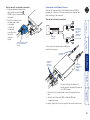
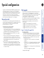
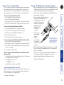
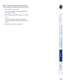
® ® NETWORK SERVICES AUGUST 2004 ACU5013A ServSwitch Wizard Extender USER GUIDE CUSTOMER SUPPORT INFORMATION Order toll-free in the U.S.: Call 877-877-BBOX (outside U.S. call 724-746-5500) FREE technical support 24 hours a day, 7 days a week: Call 724-746-5500 or fax 724-746-0746 Mailing address: Black Box Corporation, 1000 Park Drive, Lawrence, PA 15055-1018 Web site: www.blackbox.com • E-mail: [email protected] ® Further information Troubleshooting ........................................................................ 13 Getting assistance ..................................................................... 13 Other products in the Wizard range....................................... 14 Safety information ................................................................... 14 Radio Frequency Energy .......................................................... 15 European EMC directive 89/336/EEC ................................... 15 Federal Communications Comission and Canadian Department of Communications radio frequency interference statements ............................................................................ 15 Certification notice for equipment used in Canada ............... 16 Normas Oficiales Mexicanas (NOM) ........................................ 17 Instrucciones de seguridad .................................................. 17 Installation ................................................................................... 3 Stage A - Configuration switch settings .............................. 3 Stage B - Mounting the module – desk or rack ................... 4 Stage C – Connections ........................................................... 4 Connections at the Wizard Extender ACU5013A ............ 4 Connections at the Remote Receivers.............................. 6 Operation .................................................................................... 7 Power and activity indicator............................................. 7 ‘Two-in, two-out’ mode ..................................................... 7 ‘One-in, two-out’ mode .................................................... 7 Installation and operation Password override ....................................................................... 8 Flash upgrade .............................................................................. 8 Stage A - Download the upgrade files ................................. 8 Stage B - Create a startup diskette ....................................... 9 Stage C – Reconfigure the connections and begin.............. 9 Stage D - Return the connections to their usual state ...... 10 Video compensation ............................................................ 11 The Skew Compensator ....................................................... 12 ‘One-in, two-out’ mode ......................................................... 2 ‘Two-in, two-out’ mode ......................................................... 2 Supplied items ........................................................................ 2 Special configuration Welcome Contents 1 ® Supplied items Connection from the primary video controller within the computer 55 Wizard Extender ACU5013A module 72 4- ® 74 6- CA 2 BLE CA 1 BLE rd C A L LO 2 1 UTP 1 RECEIVER 2 (ACU5011A) PSU ‘Two-in, two-out’ mode When the computer has a second video controller, this mode allows a keyboard, video and mouse set to form a remote control connection, while the secondary video channel is transmitted to a second video monitor in the same (or an alternative) location. Y-CABLE UTP 2 KEYBD VIDEO 2 2 VIDEO 1 1 Wizard Extender ACU5013A Power and signal activity indicator Optional connection to power adapter (required when no keyboard connection will be made Y-cable KVM cable (EHN408-0005) RECEIVER (ACU5011A) PC MOUSE Switch bank to determine certain modes and functions PSU 2 Secondary video cable (EVNPS06-0005) 1 Wizard Extender ACU5013A Twisted pair connection to primary (UTP 1) and secondary (UTP 2) remote receivers Socket for Y-cable to which connections from the keyboard and mouse ports of the computer are attached 1 4 2 VIDEO 1 PSU 3 UTP 2 2 Y-CABLE KEYBD 1 MOUSE Expansion connector for future use and optional power input ON 1 RECEIVER 1 (ACU5011A) PC 2 W iz a BL AC K BO X Ex te nd er ‘One-in, two-out’ mode Allows one computer to be accessed by two separate keyboard, video and mouse sets. Control of the system is arbitrated on a ‘first come, first served’ basis, with control being relinquished two seconds after the last keyboard or mouse action. Connection from the secondary video controller within the computer (if used) 00 ® R PO WE Thank you for choosing the ServSwitch Wizard Extender ACU5013A. Used in conjunction with two remote receivers, this compact unit allows you to control (or monitor) one computer from two separate locations. The long distance links are made via Category 5 or higher cabling and each of the two spurs can be up to 650ft (200m) in length. The Wizard Extender ACU5013A can be used in two ways: Welcome UTP 1 RECEIVER (ACU5011A) PSU Self-adhesive rubber feet Power supply plus mains cable (PS649) plus power cord (EPWR08) 2 ® OFF: Normal operation ON: Transparent mode O ON N 1 OFF: Normal operation ON: Flash upgrade/reset password modes 2 34 OFF: Normal operation ON: Reset Wizard Extender ACU5013A OFF: Two-in, two-out mode ON: One-in, two-out mode ON 1 2 34 Note: When shipped, all switches are set in the OFF positions and this will produce normal operation in the ‘Two-in, two-out’ mode. To select the alternative, ‘One-in, two-out’ mode, simply change switch 3 to the ON position. Switch 2 OFF: Normal operation. ON: Set transparent mode. Use this setting if the Wizard Extender ACU5013A is to be used with KVM switches produced by other manufacturers. Cascaded KVM switches often use special signals to set or identify conditions. In transparent mode, the Wizard Extender ACU5013A will pass the signals without attempting to interpret them. Switch 3 OFF: ‘Two-in, two-out’ mode. Use this setting when the computer has a second video controller that must be fed to a second video monitor alongside, or separate from, the primary monitor, keyboard and mouse. ON: ‘One-in, two-out’ mode. Use this setting when two separate keyboard, video and mouse sets are required to control one computer. Switch 4 OFF: Normal operation. ON: Suspend operation and reset the Wizard Extender ACU5013A. Use this setting momentarily to produce the same effect as removing and restoring power if incorrect operation has occurred. Return the switch to the OFF position to allow normal operation to continue. The basic operation of the Wizard Extender ACU5013A is controlled by the bank of four switches located on the side of the module. The switches are monitored at all times and may be changed when power is on or off (the only exception to this rule is switch 1 which initiates slightly different functions depending on the power state when it is switched). Stage A - Configuration switch settings The installation of the Wizard Extender ACU5013A is straightforward and can best be achieved in most cases by following these stages: • Stage A Check or set the configuration switch settings • Stage B Mount the module • Stage C Connect the cables Switch 1 OFF: Normal operation. ON: (Before power is applied) Places the module into upgrade mode so that the internal software can be changed. Please see the ‘Flash upgrade’ section in the ‘Special configuration’ section. ON: (While power is applied) Places the connected receiver modules into password override mode. This allows any pre-configured passwords to be altered - particularly useful when they have been lost or forgotten. Please see the ‘Password override’ section in the ‘Special configuration’ chapter. Installation Installation and operation 3 2 34 5V 1A 1 Pan-head screw Countersunk screws x 2 5 Use the third (pan-head) screw, in the top hole of the rack securing plate to fasten the module to the rack. Power connection The Wizard Extender ACU5013A can obtain its power perfectly well from its keyboard connection to the computer system. Thus, if the keyboard connection is made to the computer, the power adapter is not necessary. If, however, the Wizard Extender ACU5013A will not use a keyboard connection, then the power supply must be used: 1 Attach the output connector of the power supply to the socket at the front edge of the module labelled POWER. 2 Insert the IEC connector of the supplied power lead into the corresponding socket of the power supply. Connect the other end of the power lead to a nearby mains socket. When power is applied, either via the keyboard connector or power supply, the small indicator situated on the front edge of the module adjacent the POWER socket will glow red. Note: It is also possible to supply power to the module using the Expansion connector situated adjacent to the configuration switches. The use of this connector is beyond the scope of this user guide. Note: The module contains an internal automatic cut-out fuse to protect against power surges. To reset, remove power from the module for one second and then reconnect. Rack mount Note: The module switches are not accessible once it is inserted into the rack, therefore, check all settings before insertion. 1 Place the rack securing plate (available as a separate kit) onto the front of the module and secure it with the two countersunk screws. 2 Orient the Wizard Extender ACU5013A module on its side so that its labelled face is the correct way up and the two blue video connectors are facing into the rack. 3 Slide the module into the required rack position. The rectangular cut-out in the front upper lip of the rack allows the two screws on the module’s upper edge to slide through. 4 The rack mount chassis has a series of holes in its floor that are spaced to accommodate the two screws on the module’s lower edge. Ensure that the screws correctly locate into the two holes of the chosen slot. The rack securing plate Rack securing on the module should now be plate flush with the front of the rack mount chassis. Connections at the Wizard Extender ACU5013A Desk mount Apply the supplied self-adhesive rubber feet to the underside of the module. Most connections to the Wizard Extender ACU5013A are common to both of the operational modes, while other connections differ depending on whether the ‘Two-in, two-out’ or ‘One-in, two-out’ modes are selected. The Wizard Extender ACU5013A can be situated on a desk (or floor) or alternatively, for larger installations, mounted within an optional rack mount chassis. ON ® Stage C – Connections Stage B - Mounting the module – desk or rack 4 Connection from the mouse port of the computer ® • Attach the blue video connector to the VIDEO 1 socket at the back end of the module. When rack-mounted, a route from the front to the rear of the module must be maintained for this connection to be Connection from the possible. primary video controller within the computer 3 At the other end of the KVM cable, attach the keyboard, mouse and video connectors to the appropriate sockets at the rear of the computer system. Note: For computers equipped with two video controllers, the video connector on the KVM cable should go to the output socket of the primary controller. These are all of the connections required at the Wizard Extender ACU5013A end if you are using the ‘One-in, two-out’ mode (Switch 3: ON) – Now go to the sub-section ‘Connections at the Remote Receivers’. However, if you are using the ‘Two-in, two-out’ mode (Switch 3: OFF), one further connection must be made at the Wizard Extender ACU5013A end - shown overleaf. Connection from the keyboard port of the computer Y-cable & KVM cable connections The Wizard Extender ACU5013A uses a Y-cable to split-out the keyboard and mouse connections from the single socket on the front end of the module. 1 Insert the main plug of the Y-cable into the round socket labelled Supplied Y-cable on the front edge of the module. 2 Using the supplied KVM cable: • Attach the light purple keyboard connector to the Y-cable socket labelled . • Attach the green mouse connector to the Y-cable socket labelled . If the computer has a 5-pin DIN (AT) keyboard connection, use an optional ‘PS/2 to AT’ converter. Twisted pair cable connections The Wizard Extender ACU5013A uses two twisted Connection to primary pair cables (Category 5 or remote receiver higher) to link to the two separate remote receiver units. Insert the connectors from the two twisted pair Connection to secondary cables into the remote receiver connectors front end of the module. Note: In the ‘Two-in, two-out’ mode, the UTP 1 connector provides keyboard, video and mouse data, while the UTP 2 connector supplies only a secondary video signal. 5 Although not supplied as part of the Wizard Extender ACU5013A package, the connection of the remote receivers are important and differ according to the mode used. RECEIVER 1 (ACU5011A) MOUSE Y-CABLE UTP 2 KEYBD 2 VIDEO 1 1 Wizard Extender ACU5013A PSU 2 1 UTP 1 Single video connection RECEIVER 2 (ACU5011A) Both receivers have keyboards, video monitors and mice attached in the same manner (PSU p/n: PS649) PC ‘One-in, two-out’ mode connections PSU In this mode, both remote receiver modules are wired in the same way: Connections to keyboard, mouse and video monitor Twisted pair connection from the Wizard Extender ACU5013A The switch settings should be set for normal operation. Generally this means all set to OFF, however: • Switches 2 and 3 can be altered to select the required hot keys, and • Switch 4 selects Automatic (OFF) or Manual (ON) video compensation mode. For details, please refer to the user guide for the remote receiver used. Power supply connection Connection from the secondary video controller within the computer ® Connections at the Remote Receivers ‘Two-in, two-out’ second video connection 1 Using the supplied secondary video cable, attach one end to the VIDEO 2 socket at the back end of the module. 2 Attach the other end of the secondary video cable to the output socket of the second video controller at the rear of the computer system. 6 ‘Two-in, two-out’ mode connections VIDEO 2 2 VIDEO 1 1 Wizard Extender ACU5013A PSU 2 1 UTP 1 Primary and secondary video connections RECEIVER PSU Primary receiver with keyboard, video monitor and mouse attached In this mode, the primary and secondary remote receiver modules are connected differently. For the primary receiver, use the connection details shown on the previous page. For the secondary receiver, connect the module as shown here: Power supply connection Connection to secondary video monitor Second twisted pair connection from the Wizard Extender ACU5013A The switch settings should be set for normal operation. Generally this means all set to OFF, however: • Switches 2 and 3 can be altered to select the required hot keys, and • Switch 4 selects Automatic (OFF) or Manual (ON) video compensation mode. For details, please refer to the user guide for the remote receiver used. On the front panel of the Wizard Extender ACU5013A a small recessed indicator provides confirmation of power and activity, as follows: • Constant red - power applied, no communication activity. Recessed activity • Flickering red - power applied, indicator communication occuring. • Slow flashing red - module is in flash upgrade mode. ‘Two-in, two-out’ mode In this mode, operation should be straightforward with the main video image appearing on the monitor connected to the primary receiver. The keyboard and mouse connected at the primary receiver will have total control over the system. The output from the computer’s second video controller should then appear on the monitor connected to the secondary receiver. If there is no image on the secondary monitor, first check that the computer is actually generating a second screen image. ‘One-in, two-out’ mode In this mode, control of the computer is arbitrated on a first come, first served basis. In the standby state, control is available to both receivers and their keyboard indicators both show their current Num Lock, Caps Lock and Scroll Lock conditions. At the moment that a key is pressed or a mouse is moved on one receiver, the other receiver is temporarily locked out (the video image remains). The keyboard indicators on the locked out system then begin to flash to confirm its status: After two seconds of inactivity from the receiver that currently has control, the system returns to its standby condition and the keyboard indicators of the locked out system return to their ‘natural’ state. UTP 2 KEYBD Power and activity indicator Y-CABLE MOUSE Secondary reciever with video monitor only attached RECEIVER PC ® Operation 7 ® Special configuration To override remote receiver passwords 1 Power down both remote receivers. Note: If you wish to leave one of the receivers unchanged, leave it switched off during this process – do not power the unit while the configuration switch on the Wizard Extender ACU5013A is set. 2 With power to the Wizard Extender ACU5013A still on, change switch 1 to the ON position. 3 Power on one or both of the remote receivers. The powered on receiver(s) will go directly into configuration mode so that new passwords may be set (without requiring the old one(s). For details about setting passwords, please refer to the user guide for the remote receivers. 4 Once the remote receiver(s) have entered configuration mode, return switch 1 of the Wizard Extender ACU5013A back to its OFF position. Note: If switch 1 remains ON, then the Wizard Extender ACU5013A will enter upgrade mode when it is repowered and will not operate normally. Stage A - Download the upgrade files To download the files 1 Contact Black Box technical support (see front cover) for details about how to locate and download the appropriate upgrade file. 2 Decompress the downloaded file. Depending on the chosen option, there will be a collection of suitable files. As a minimum, there should be the following files: • AUTOEXEC.BAT – directs the computer to run the upgrade programs. • XKVMxxx.EXE – this is the upgrade program that causes upgrade data to be sent to the Wizard Extender ACU5013A from the computer. • XDVTxxx.HEX – this is the firmware file for the Wizard Extender ACU5013A. Where xxx is the upgrade version number. This mode allows you to override any passwords that have been set at the remote receiver(s) and place them into configuration mode so that new ones may be set. This feature is particularly useful when passwords have been lost or forgotten. As part of the continual development and improvement process across our range of products, software upgrades are occasionally made available. The Wizard Extender ACU5013A’s internal flash memory and our unique keyboard-link upgrade technique allow you to utilize software upgrades in a straightforward manner. Note: Wizard receiver modules can also be flash upgraded. For further details, please refer to the user guide for the remote receivers. To perform a flash memory upgrade, you need to perform the following stages: • Stage A – Download upgrade files from the website • Stage B – Create a startup diskette and copy the files to it • Stage C – Reconfigure the connections and begin • Stage D - Return the connections to their usual state Password override Flash upgrade In operation, the Wizard Extender ACU5013A is generally an unseen and transparent element in the system. Most of the configurable options and usability settings (such as passwords, hotkey controls, etc.) are made at the receiver units, where the keyboards, video monitors and mice are connected. There are, however, two important configuration options particular to the Wizard Extender ACU5013A, both of which are controlled by switch 1 on its side panel. Now please follow Stage B. 8 To create a startup disk in Windows 95/98/Me 1 Insert a formatted diskette into the floppy disk drive. 2 Select ‘Start’, then ‘Settings’ and then ‘Control Panel’. 3 Double click on the ‘Add/Remove Programs’ icon. 4 Select the ‘Startup Disk’ tab. 5 Click ‘Create Disk’ and follow the instructions. To create a startup disk in Windows 95/98 (alternative method) 1 Insert a diskette into the floppy disk drive. 2 Right mouse click on the ‘3½ Floppy (A:)’ icon and select ‘Format’. 3 Select the ‘Full format’ option and ensure that the ‘Copy system files’ box is checked. 4 Select ‘Start’ to format the disk. To create a startup disk from MS-DOS or a DOS window within Windows 95/98 1 Insert a diskette into the floppy disk drive and check that the drive is configured as drive A (it usually is). 2 At the DOS prompt (C:\>) type: Now please follow Stage D. To create a startup disk in Windows XP 1 Insert a diskette into the floppy disk drive. 2 Select ‘Start’ and then ‘My Computer’. 3 Right mouse click on the ‘3½ Floppy (A:)’ icon and select ‘Format’. 4 Check the ‘Create an MS-DOS startup disk’ box and select ‘Start’. 1 On the computer from which you will run the upgrade, ensure that its BIOS settings will allow it to boot from the floppy diskette drive, rather than booting immediately from the hard drive. 2 Switch off the computer and Wizard Extender ACU5013A (if a power supply is connected). 3 Disconnect both twisted pair cables from the Wizard Extender ACU5013A. For the upgrade process, the only connection that is essential, between the computer and the Wizard Extender ACU5013A, is the keyboard port connection. 4 So that you can check upgrade progress, Remove the twisted pair connect a connections and ensure that the link to the computer’s keyboard monitor directly port is correct - the mouse and to the primary video port connections are unimportant for this operation video port of the computer. 5 On the Wizard Extender ACU5013A, change switch 1 to the ON position. Ensure that the upgrade diskette is in the floppy disk drive of the computer. 6 Power on the computer (and Wizard Extender ACU5013A, if it is using the power adapter). The upgrade process will start automatically and confirmation will be given on screen. For this stage you will need a 3½ floppy diskette that is either blank or has existing contents that are no longer required. The write protect tab must be moved to the ‘unprotected’ position. Depending on your operating system, use one of the following to create a startup disk: ® Stage C – Reconfigure the connections and begin Stage B - Create a startup diskette Copy the downloaded files to the disk Once the diskette has been formatted, using Windows Explorer or the My Computer option, copy the downloaded and decompressed files from your computer to the floppy diskette. FORMAT A: /S and follow the instructions given by DOS. Now please follow Stage C. 9 ® Once the upgrade process has been completed, perform the following to return the system to its previous state. 1 Switch off the computer and Wizard Extender ACU5013A (if a power supply is connected). 2 On the Wizard Extender ACU5013A, change switch 1 to the OFF position. 3 Reinstate the twisted pair connections and also the video connection(s) between the Wizard Extender ACU5013A and the computer. 4 Remove the diskette from the system and reboot. Stage D - Return the connections to their usual state 10 ® If video compensation cannot solve the problem If automatic and manual compensation is unable to solve the problem, an additional module called a ‘Skew Compensator’ may be required. Please see the next section for details. • Optionally press to make the circuitry calculate and apply an automatic compensation level - you can use this as a starting point for your fine tuning. • Press to increase compensation by one fine step, • Press to increase compensation by one coarse step, to select the neutral setting (no compensation), • Press • Press to decrease compensation by one coarse step, • Press to decrease compensation by one fine step. Note: In total there are twenty two fine steps from one end of the scale to the other. One coarse step jumps roughly five fine steps. Note: If the monitor goes blank and switches off (due to extreme over compensation) press the key to restore it. 4 When no shadows are visible and the displayed images have crisp edges, press to exit configuration mode. The new compensation setting will be stored, even when power is removed or if a complete reset is initiated. The setting should not require further changes, unless the cabling arrangement is altered. Note: If REMOTE switch 4 is returned to its OFF position, the video compensation level will be recalculated and set at the next power on. To display a suitable high contrast image The best way to clearly view the effects of compensation is to display a high contrast image, with vertical edges, on the screen. • Open a word processor, type the capital letter ‘H’, or ‘M’ and increase the point size to 72 or higher. For best results, the background should be white and the character should be black. • A BLACK shadow on the right of the High contrast White or black black character shadow on character indicates UNDER on white right side background indicates the compensation. need for compensation • A WHITE shadow on the right of the character indicates OVER compensation. To manually adjust the video compensation 1 Change REMOTE switch 4 to the ON position. 2 Press, in unison, the hotkeys (by default, and ) along with to enter configuration mode. The three keyboard indicators (‘Num Lock’, ‘Caps Lock’ and ‘Scroll Lock’) will now begin to flash in sequence. The speed of the sequence indicates the level of compensation currently applied: the slower the rate, the less compensation is being applied. 3 While watching the displayed high contrast screen image, now adjust the video compensation setting using the following keys: The Wizard Extender incorporates video compensation circuitry to maximize the picture quality for any given length of twisted pair cable. The amount of video compensation required increases proportionally with the length of cable run that is being used. The Wizard Extender can automatically correct the video compensation settings for any length of cable, however in certain circumstances you may wish to finely adjust and fix the compensation level to suit personal preferences - this can be done by switching to manual compensation mode. Video compensation 11 ® The Skew Compensator 3 Press, in unison, the hotkeys (by default, and ) along with to enter configuration mode. 4 Enter one of the following codes, depending on the type of keyboard being used: • QWERTY keyboard (i.e. English, German), press • AZERTY keyboard (French), press The screen will go blank for a few seconds while the measurements are made. When the picture is restored, a report, similar to that shown above right will be generated. Indicates the Skew Compensator switches that would need to be set in order to correct the current cable-length mismatch 5 Press to exit configuration mode. Communicate the report findings to Black Box Technical Support. To produce a skew compensator report 1 Ensure that the video image is correctly compensated using the procedure outlined in the previous section (the report will be more accurate if internal compensation is correctly applied). 2 Open an application that can display typed keys as screen characters - e.g. a word processor or Windows Notepad. The skew report will be written to the application by generating a series of ‘faked’ keypresses. Indicates the differences in length between the three cable pairs. In this case the Blue pair is the shortest and the Green pair is 1 meter longer The twisted pair cabling supported by the Wizard Extender set (category 5, or higher) consists of four pairs of cables. Three of these pairs are used by the modules to convey red, green and blue video signals to the remote video monitor. Due to the slight difference in twist rate between these three pairs, the red, green and blue video signals may not arrive at the monitor together. This is visible as seperate color shadows on high contrast screen images. This effect is particularly apparent when using higher screen resolutions and some types of category 5e cables. 12345678 In this situation, Black Box recommends the use of an optional module called the ‘Wizard Skew Compensator’ (part code: ACU5100A). This manually adjustable, passive device can apply fine timing changes to the video signals ensuring they arrive together thus 8 8 Wizard 7 7 data signal removing the color separation. The 6 Wizard red REMOTE module includes a skew report 6 3 3 video signal function that indicates how to set the 5 5 Wizard green multiple switches on the Skew 4 4 video signal Compensator. This report function can 2 2 Wizard blue also be a useful tool in determining if a 1 1 video signal skew compensator is required. 12 ® In ‘two-in, two-out’ mode no video image is received on the second screen. • Temporarily disconnect the second video link to the Wizard Extender ACU5013A, connect a monitor directly to the computer secondary video port and check for a correct video image output on this channel. Power is applied via the power supply but Wizard Extender ACU5013A (or remote receiver) operation has stopped. • Each module has an internal automatic cut-out fuse to protect against power surges. To reset, remove power from the module for one second and then reconnect. Getting assistance If you are still experiencing problems after checking the list of solutions in the Troubleshooting section then please refer to the customer support information supplied on the front cover. Video image at the remote receiver is distorted or shadows appear to the right of displayed objects. Video compensation is required to overcome the delay effects of long twisted pair wiring, especially when running through a patch panel. If video problems persist: • All Wizard Extender receivers contain automatic circuitry to overcome all but the most severe cases. If a Wizard Extender receiver fails to automatically correct a video problem, try adjusting it manually. For details about manual video compensation, please refer to the user guide for the Wizard Extenders. • For non Wizard Extender receivers (which do not have automatic video compensation), manual video compensation should be performed. Please refer to the user guide for the receiver. • If your video image has colored shadows you may need to use the optional Wizard Skew Compensator. This stand-alone passive module allows you to finely tune the red, green and blue video signal timings (each of which is fed along separate twisted pair sets) to overcome most screen image problems. No video image is received at either of the remote receivers. • Check that the power/activity indicators are lit on the Wizard Extender ACU5013A as well as the receivers - if they are not, then there is a power problem. When keys are pressed or the mouse is moved, check that the indicators flicker – if they do not then there could be a twisted pair link problem or a problem with one of the modules. • If possible, try using an alternative twisted pair connection between the Wizard Extender ACU5013A and the receiver. • If the receiver is severely over compensated, the monitor may not be able to display a picture. Try manually reducing the video compensation. Please refer to the user guide for the receiver. • Temporarily disconnect the video link to the Wizard Extender ACU5013A, connect a monitor directly to the computer video port and check for a correct video image output. If you experience problems when installing or using the Wizard Extender ACU5013A, please check through this section for a possible solution. If your problem is not listed here and you cannot resolve the issue, then please refer to the ‘Getting assistance’ section. Troubleshooting Further information 13 • • • • For use in dry, oil free indoor environments only. Warning - live parts contained within power adapter. No user serviceable parts within power adapter - do not dismantle. Plug the power adapter into a socket outlet close to the module that it is powering. Replace the power adapter with a manufacturer approved type only. Do not use the power adapter if the power adapter case becomes damaged, cracked or broken or if you suspect that it is not operating properly. If you use a power extension cord with the module, make sure the total ampere rating of the devices plugged into the extension cord does not exceed the cord’s ampere rating. Also, make sure that the total ampere rating of all the devices plugged into the wall outlet does not exceed the wall outlet’s ampere rating. Do not attempt to service the module yourself. • • • • The following related items are available: • Remote receiver module ACU5011A Two of these are required, one at the end of both remote cable spurs emanating from the Wizard Extender ACU5013A. These modules convert the coded signals from the Wizard Extender ACU5013A back into native formats used by keyboards, video monitors and mice. • Wizard Skew compensator ACU5100A Removes color split in video signals caused by certain Cat 5e and 6 cables. Required only in certain installations with long cable lengths and high video resolutions. • Rack mount chassis ACU5000A This 19” chassis allows multiple modules to be neatly arranged within a standard cabinet. Securing plates and screws are supplied separately for each module for use with the rack mount chassis. • Power distribution module PS5000 Provides power for up to four modules to reduce mains power socket requirements. • Rack mount securing plates • single slot blanking plate ACU5003 • quad slot blanking plate ACU5004 ® Safety information Other products in the Wizard range 14 ® Radio Frequency Energy This equipment generates, uses, and can radiate radio frequency energy and if not installed and used properly, that is, in strict accordance with the manufacturer’s instructions, may cause interference to radio communication. It has been tested and found to comply with the limits for a Class A computing device in accordance with the specifications in Subpart B of Part 15 of FCC rules, which are designed to provide reasonable protection against such interference when the equipment is operated in a commercial environment. Operation of this equipment in a residential area is likely to cause interference, in which case the user at his own expense will be required to take whatever measures may be necessary to correct the interference.Changes or modifications not expressly approved by the party responsible for compliance could void the user’s authority to operate the equipment.This digital apparatus does not exceed the Class A limits for radio noise emission from digital apparatus set out in the Radio Interference Regulation of the Canadian Department of Communications.Le présent appareil numérique n’émet pas de bruits radioélectriques dépassant les limites applicables aux appareils numériques de la classe A prescrites dans le Règlement sur le brouillage radioélectrique publié par le ministère des Communications du Canada. Federal Communications Comission and Canadian Department of Communications radio frequency interference statements This equipment has been tested and found to comply with the limits for a class A computing device in accordance with the specifications in the European standard EN55022. These limits are designed to provide reasonable protection against harmful interference. This equipment generates, uses and can radiate radio frequency energy and if not installed and used in accordance with the instructions may cause harmful interference to radio or television reception. However, there is no guarantee that harmful interference will not occur in a particular installation. If this equipment does cause interference to radio or television reception, which can be determined by turning the equipment on and off, the user is encouraged to correct the interference with one or more of the following measures: (a) Reorient or relocate the receiving antenna. (b) Increase the separation between the equipment and the receiver. (c) Connect the equipment to an outlet on a circuit different from that to which the receiver is connected. (d) Consult the supplier or an experienced radio/TV technician for help. European EMC directive 89/336/EEC A Category 5 (or better) twisted pair cable must be used to connect the Wizard units in order to maintain compliance with radio frequency energy emission regulations and ensure a suitably high level of immunity to electromagnetic disturbances.All other interface cables used with this equipment must be shielded in order to maintain compliance with radio frequency energy emission regulations and ensure a suitably high level of immunity to electromagnetic disturbances. 15 ® The Canadian Department of Communications label identifies certified equipment. This certification means that the equipment meets certain telecommunications-network protective, operation, and safety requirements. The Department does not guarantee the equipment will operate to the user’s satisfaction. Before installing this equipment, users should ensure that it is permissible to be connected to the facilities of the local telecommunications company. The equipment must also be installed using an acceptable method of connection. In some cases, the company’s inside wiring associated with a single-line individual service may be extended by means of a certified connector assembly (extension cord). The customer should be aware that compliance with the above conditions may not prevent degradation of service in some situations. Repairs to certified equipment should be made by an authorized Canadian maintenance facility—in this case, your supplier. Any repairs or alterations made by the user to this equipment, or equipment malfunctions, may give the telecommunications company cause to request the user to disconnect the equipment. Users should ensure for their own protection that the electrical ground connections of the power utility, telephone lines, and internal metallic water pipe system, if present, are connected together. This precaution may be particularly important in rural areas. CAUTION: Users should not attempt to make such connections themselves, but should contact the appropriate electric inspection authority, or electrician, as appropriate. The LOAD NUMBER (LN) assigned to each terminal device denotes the percentage of the total load to be connected to a telephone loop which is used by the device, to prevent overloading. The termination on a loop may consist of any combination of devices, subject only to the requirement that the total of the load numbers of all the devices does not exceed 100. Certification notice for equipment used in Canada 16 ® Normas Oficiales Mexicanas (NOM) electrical safety statement 14 El equipo eléctrico debe ser limpiado únicamente de acuerdo a las recomendaciones del fabricante. 15 En caso de existir, una antena externa deberá ser localizada lejos de las lineas de energia. 16 El cable de corriente deberá ser desconectado del cuando el equipo no sea usado por un largo periodo de tiempo. 17 Cuidado debe ser tomado de tal manera que objectos liquidos no sean derramados sobre la cubierta u orificios de ventilación. 18 Servicio por personal calificado deberá ser provisto cuando: A:El cable de poder o el contacto ha sido dañado; u B: Objectos han caído o líquido ha sido derramado dentro del aparato; o C: El aparato ha sido expuesto a la lluvia; o D: El aparato parece no operar normalmente o muestra un cambio en su desempeño; o E: El aparato ha sido tirado o su cubierta ha sido dañada. 1 Todas las instrucciones de seguridad y operación deberán ser leídas antes de que el aparato eléctrico sea operado. 2 Las instrucciones de seguridad y operación deberán ser guardadas para referencia futura. 3 Todas las advertencias en el aparato eléctrico y en sus instrucciones de operación deben ser respetadas. 4 Todas las instrucciones de operación y uso deben ser seguidas. 5 El aparato eléctrico no deberá ser usado cerca del agua—por ejemplo, cerca de la tina de baño, lavabo, sótano mojado o cerca de una alberca, etc. 6 El aparato eléctrico debe ser usado únicamente con carritos o pedestales que sean recomendados por el fabricante. 7 El aparato eléctrico debe ser montado a la pared o al techo sólo como sea recomendado por el fabricante. 8 Servicio—El usuario no debe intentar dar servicio al equipo eléctrico más allá a lo descrito en las instrucciones de operación. Todo otro servicio deberá ser referido a personal de servicio calificado. 9 El aparato eléctrico debe ser situado de tal manera que su posición no interfiera su uso. La colocación del aparato eléctrico sobre una cama, sofá, alfombra o superficie similar puede bloquea la ventilación, no se debe colocar en libreros o gabinetes que impidan el flujo de aire por los orificios de ventilación. 10 El equipo eléctrico deber ser situado fuera del alcance de fuentes de calor como radiadores, registros de calor, estufas u otros aparatos (incluyendo amplificadores) que producen calor. 11 El aparato eléctrico deberá ser connectado a una fuente de poder sólo del tipo descrito en el instructivo de operación, o como se indique en el aparato. 12 Precaución debe ser tomada de tal manera que la tierra fisica y la polarización del equipo no sea eliminada. 13 Los cables de la fuente de poder deben ser guiados de tal manera que no sean pisados ni pellizcados por objetos colocados sobre o contra ellos, poniendo particular atención a los contactos y receptáculos donde salen del aparato. Instrucciones de seguridad 17 ® Black Box Network Services (UK) Ltd, 464 Basingstoke Road, Reading, Berkshire, RG2 0BG, United Kingdom Tel: +44 (0)118 965 5100 Black Box Corporation, 1000 Park Drive, Lawrence, PA 15055-1018, United States of America Tel: +1-724-746-5500 Fax: +1-724-746-0746 © 2004 Black Box Corporation All trademarks are acknowledged. 18