1
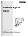
ENGLISH
Cordless Jig Saw
MODEL 4331D
MODEL 4333D
002700
I N S T R U C T I O N
M A N U A L
WARNING:
For your personal safety, READ and UNDERSTAND before using.
SAVE THESE INSTRUCTIONS FOR FUTURE REFERENCE.
SPECIFICATIONS
Model
4331D
Length of stroke
Max. cutting capacities
4333D
26 mm
Wood
65 mm
Mild steel
10 mm
Aluminum
20 mm
-1
Strokes per minute (min )
500 - 2,800
Overall length
500 - 2,600
280 mm
Net weight
2.5 kg
2.9 kg
Rated voltage
D.C. 12 V
D.C. 14.4 V
• Due to our continuing programme of research and development, the specifications herein are subject to change
without notice.
• Note: Specifications may differ from country to country.
For European countries only
END001-1
Noise and Vibration
Symbols
The typical A-weighted sound pressure level is 81 dB (A).
The following show the symbols used for the equipment.
Uncertainty is 3 dB(A).
Be sure that you understand their meaning before use.
The noise level under working may exceed 85 dB (A).
– Wear ear protection. –
..................Only for EU countries
The typical weighted root mean square acceleration
Do not dispose of electric equipment
value is 9 m/s2.
together with household waste
These values have been obtained according to
material!
EN60745.
In observance of European Directive
2002/96/EC on waste electric and
EC-DECLARATION OF CONFORMITY
electronic
equipment
and
its
We declare under our sole responsibility that this product
implementation in accordance with
is in compliance with the following standards of standnational law, electric equipment that
ardized documents;
have reached the end of their life
EN60745, EN55014 in accordance with Council Direcmust be collected separately and
tives, 89/336/EEC, 98/37/EC.
returned to an environmentally
compatible recycling facility.
Yasuhiko Kanzaki CE2005
Intended use
The tool is intended for the sawing of wood, plastic and
metal materials.
Director
As a result of the extensive accessory and saw blade
MAKITA INTERNATIONAL EUROPE LTD.
program, the tool can be used for many purposes and is
Michigan Drive, Tongwell, Milton Keynes, Bucks MK15
very well suited for curved or circular cuts.
8JD, ENGLAND
Responsible manufacturer:
Makita Corporation Anjo Aichi Japan
2
GENERAL SAFETY RULES
GEA002-3
WARNING:
Read all instructions. Failure to follow all instructions listed below may result in
electric shock, fire and/or serious injury. The term “power tool” in all of the
warnings listed below refers to your mains-operated (corded) power tool or batteryoperated (cordless) power tool.
SAVE THESE INSTRUCTIONS
Work area safety
1.
Keep work area clean and well lit. Cluttered and
dark areas invite accidents.
2.
Do not operate power tools in explosive atmospheres, such as in the presence of flammable
liquids, gases or dust. Power tools create sparks
which may ignite the dust or fumes.
3.
Keep children and bystanders away while operating a power tool. Distractions can cause you to
lose control.
Electrical safety
4.
Power tool plugs must match the outlet. Never
modify the plug in any way. Do not use any
adapter plugs with earthed (grounded) power
tools. Unmodified plugs and matching outlets will
reduce risk of electric shock.
5.
Avoid body contact with earthed or grounded
surfaces such as pipes, radiators, ranges and
refrigerators. There is an increased risk of electric
shock if your body is earthed or grounded.
6.
Do not expose power tools to rain or wet conditions. Water entering a power tool will increase the
risk of electric shock.
7.
Do not abuse the cord. Never use the cord for
carrying, pulling or unplugging the power tool.
Keep cord away from heat, oil, sharp edges or
moving parts. Damaged or entangled cords
increase the risk of electric shock.
8.
When operating a power tool outdoors, use an
extension cord suitable for outdoor use. Use of a
cord suitable for outdoor use reduces the risk of
electric shock.
Personal safety
9.
Stay alert, watch what you are doing and use
common sense when operating a power tool. Do
not use a power tool while you are tired or under
the influence of drugs, alcohol or medication. A
moment of inattention while operating power tools
may result in serious personal injury.
10. Use safety equipment. Always wear eye protection. Safety equipment such as dust mask, non-skid
safety shoes, hard hat, or hearing protection used
for appropriate conditions will reduce personal injuries.
11. Avoid accidental starting. Ensure the switch is
in the off-position before plugging in. Carrying
power tools with your finger on the switch or plugging in power tools that have the switch on invites
accidents.
12. Remove any adjusting key or wrench before
turning the power tool on. A wrench or a key left
attached to a rotating part of the power tool may
result in personal injury.
13. Do not overreach. Keep proper footing and balance at all times. This enables better control of the
power tool in unexpected situations.
14. Dress properly. Do not wear loose clothing or
jewellery. Keep your hair, clothing, and gloves
away from moving parts. Loose clothes, jewellery
or long hair can be caught in moving parts.
15. If devices are provided for the connection of
dust extraction and collection facilities, ensure
these are connected and properly used. Use of
these devices can reduce dust-related hazards.
Power tool use and care
16. Do not force the power tool. Use the correct
power tool for your application. The correct
power tool will do the job better and safer at the rate
for which it was designed.
17. Do not use the power tool if the switch does not
turn it on and off. Any power tool that cannot be
controlled with the switch is dangerous and must be
repaired.
18. Disconnect the plug from the power source and/
or the battery pack from the power tool before
making any adjustments, changing accessories,
or storing power tools. Such preventive safety
measures reduce the risk of starting the power tool
accidentally.
19. Store idle power tools out of the reach of children and do not allow persons unfamiliar with
the power tool or these instructions to operate
3
the power tool. Power tools are dangerous in the
hands of untrained users.
20. Maintain power tools. Check for misalignment or
binding of moving parts, breakage of parts and
any other condition that may affect the power
tools operation. If damaged, have the power tool
repaired before use. Many accidents are caused
by poorly maintained power tools.
21. Keep cutting tools sharp and clean. Properly
maintained cutting tools with sharp cutting edges
are less likely to bind and are easier to control.
22. Use the power tool, accessories and tool bits
etc. in accordance with these instructions and in
the manner intended for the particular type of
power tool, taking into account the working conditions and the work to be performed. Use of the
power tool for operations different from those
intended could result in a hazardous situation.
Battery tool use and care
23. Ensure the switch is in the off position before
inserting battery pack. Inserting the battery pack
into power tools that have the switch on invites accidents.
24. Recharge only with the charger specified by the
manufacturer. A charger that is suitable for one
type of battery pack may create a risk of fire when
used with another battery pack.
25. Use power tools only with specifically designated battery packs. Use of any other battery
packs may create a risk of injury and fire.
26. When battery pack is not in use, keep it away
from other metal objects like paper clips, coins,
keys, nails, screws, or other small metal objects
that can make a connection from one terminal to
another. Shorting the battery terminals together
may cause burns or a fire.
27. Under abusive conditions, liquid may be ejected
from the battery, avoid contact. If contact accidentally occurs, flush with water. If liquid contacts eyes, additionally seek medical help. Liquid
ejected from the battery may cause irritation or
burns.
Service
28. Have your power tool serviced by a qualified
repair person using only identical replacement
parts. This will ensure that the safety of the power
tool is maintained.
29. Follow instruction for lubricating and changing
accessories.
30. Keep handles dry, clean and free from oil and
grease.
4
GEB016-1
SPECIFIC SAFETY RULES
DO NOT let comfort or familiarity with product
(gained from repeated use) replace strict adherence
to jig saw safety rules. If you use this tool unsafely
or incorrectly, you can suffer serious personal injury.
1. Hold power tools by insulated gripping surfaces when performing an operation where the
cutting tool may contact hidden wiring or its
own cord. Contact with a “live” wire will make
exposed metal parts of the tool “live” and shock the
operator.
2. Use clamps or another practical way to secure
and support the workpiece to a stable platform.
Holding the work by hand or against your body
leaves it unstable and may lead to loss of control.
3. Always use safety glasses or goggles. Ordinary
eye or sun glasses are NOT safety glasses.
4. Avoid cutting nails. Inspect workpiece for any
nails and remove them before operation.
5. Do not cut oversize workpiece.
6. Check for the proper clearance beyond the
workpiece before cutting so that the blade will
not strike the floor, workbench, etc.
7. Hold the tool firmly.
8. Make sure the blade is not contacting the workpiece before the switch is turned on.
9. Keep hands away from moving parts.
10. Do not leave the tool running. Operate the tool
only when hand-held.
11. Always switch off and wait for the blade to
come to a complete stop before removing the
blade from the workpiece.
12. Do not touch the blade or the workpiece immediately after operation; they may be extremely
hot and could burn your skin.
13. Do not operate the tool at no-load unnecessarily.
14. Some material contains chemicals which may
be toxic. Take caution to prevent dust inhalation and skin contact. Follow material supplier
safety data.
15. Always use the correct dust mask/respirator for
the material and application you are working
with.
SAVE THESE INSTRUCTIONS.
WARNING:
MISUSE or failure to follow the
safety rules stated in this instruction
manual may cause serious personal
injury.
IMPORTANT SAFETY INSTRUCTIONS FOR
BATTERY CARTRIDGE
1.
Do not disassemble battery cartridge.
3.
If operating time has become excessively
shorter, stop operating immediately. It may
result in a risk of overheating, possible burns
and even an explosion.
4.
5.
6.
(1) Do not touch the terminals with any conductive material.
Before using battery cartridge, read all instructions and cautionary markings on (1) battery
charger, (2) battery, and (3) product using battery.
2.
ENC004-1
(2) Avoid storing battery cartridge in a container with other metal objects such as
nails, coins, etc.
(3) Do not expose battery cartridge to water or
rain.
A battery short can cause a large current flow,
overheating, possible burns and even a breakdown.
If electrolyte gets into your eyes, rinse them out
with clear water and seek medical attention right
away. It may result in loss of your eyesight.
7.
Always cover the battery terminals with the battery cover when the battery cartridge is not
used.
Do not store the tool and battery cartridge in
locations where the temperature may reach or
exceed 50°C (122°F).
8.
Do not incinerate the battery cartridge even if it
is severely damaged or is completely worn out.
The battery cartridge can explode in a fire.
9.
Be careful not to drop or strike battery.
Do not short the battery cartridge:
SAVE THESE INSTRUCTIONS
Tips for maintaining maximum battery life
1.
Charge the battery cartridge before completely
discharged.
Always stop tool operation and charge the battery cartridge when you notice less tool power.
2.
Never recharge a fully charged battery cartridge.
Overcharging shortens the battery service life.
3.
Charge the battery cartridge with room temperature at 10°C - 40°C (50°F - 104°F). Let a hot battery cartridge cool down before charging it.
4.
Charge the Nickel Metal Hydride battery cartridge when you do not use it for more than six
months.
5
FUNCTIONAL
DESCRIPTION
•
002702
Installing or removing battery cartridge
•
•
•
1
2
•
1. Button
2. Battery cartridge
CAUTION:
Always be sure that the tool is switched off and the battery cartridge is
removed before adjusting or checking function on the tool.
Always switch off the tool before insertion or removal of the battery
cartridge.
To remove the battery cartridge, withdraw it from the tool while pressing
the buttons on both sides of the cartridge.
To insert the battery cartridge, align the tongue on the battery cartridge
with the groove in the housing and slip it into place. Always insert it all the
way until it locks in place with a little click. If not, it may accidentally fall
out of the tool, causing injury to you or someone around you.
Do not use force when inserting the battery cartridge. If the cartridge
does not slide in easily, it is not being inserted correctly.
002705
Selecting the cutting action
1
This tool can be operated with an orbital or a straight line (up and down) cutting action. The orbital cutting action thrusts the blade forward on the cutting
stroke and greatly increases cutting speed.
To change the cutting action, just turn the cutting action changing lever to the
desired cutting action position. Refer to the table to select the appropriate cutting action.
1. Cutting action changing lever
002788
Position
Cutting action
0
Straight line cutting action
I
Small orbit cutting action
II
Medium orbit cutting action
III
Large orbit cutting action
002708
1
Switch action
CAUTION:
Before inserting the battery cartridge into the tool, always check to see
that the switch trigger actuates properly and returns to the “OFF” position
when released.
To prevent the switch trigger from being accidentally pulled, a lock-off button is
provided.
To start the tool, push in the lock-off button and pull the switch trigger. Release
the switch trigger to stop.
•
2
1. Lock-off button
2. Switch trigger
6
Applications
For cutting mild steel, stainless steel and plastics.
For clean cuts in wood and plywood.
For cutting mild steel, aluminum and hard wood.
For cutting wood and plywood.
For fast cutting in aluminum and mild steel.
For fast cutting in wood and plywood.
002711
1
Speed adjusting dial
The tool speed can be infinitely adjusted between 500 and 2,800 (Model
4331D), 500 and 2,600 (Model 4333D) strokes per minute by turning the
adjusting dial. Higher speed is obtained when the dial is turned in the direction
of number 5; lower speed is obtained when it is turned in the direction of
number 1.
Refer to the table to select the proper speed for the workpiece to be cut. However, the appropriate speed may differ with the type or thickness of the workpiece. In general, higher speeds will allow you to cut workpieces faster but the
service life of the blade will be reduced.
1. Speed adjusting dial
002790
Workpiece to be cut
Wood
Mild steel
Stainless steel
Aluminum
Plastics
•
•
ASSEMBLY
•
Number on adjusting dial
3-5
3-5
3-4
2-3
1-4
CAUTION:
If the tool is operated continuously at low speeds for a long time, the
motor will get overloaded and heated up.
The speed adjusting dial can be turned only as far as 5 and back to 1. Do
not force it past 5 or 1, or the speed adjusting function may no longer
work.
CAUTION:
Always be sure that the tool is switched off and the battery cartridge is
removed before carrying out any work on the tool.
Installing or removing saw blade
002717
CAUTION:
Always clean out all chips or foreign matter adhering to the blade and/or
blade holder. Failure to do so may cause insufficient tightening of the
blade, resulting in a serious personal injury.
• Do not touch the blade or the workpiece immediately after operation;
they may be extremely hot and could burn your skin.
• Always secure the blade firmly. Insufficient tightening of the blade may
cause blade breakage or serious personal injury.
To install the blade, loosen the screw counterclockwise on the blade holder
with the hex wrench.
•
1
2
1. Screw
2. Hex wrench
7
002718
1
2
With the blade teeth facing forward, insert the blade into the blade holder as far
as it will go. Make sure that the back edge of the blade fits into the roller. Then
tighten the screw clockwise to secure the blade.
To remove the blade, follow the installation procedure in reverse.
NOTE:
•
Occasionally lubricate the roller.
3
1. Screw
2. Roller
3. Jig saw blade
004445
If the universal blade clamp is used, you can use blades of other makes which
have a universal shank like the one shown in the figure, with a blade width of
6.35 mm.
6.35mm
1
Installing the universal shank jig saw blade
002726
Insert the blade into the blade holder as far as it will go. Make sure that the end
of the blade shank reaches the bottom of the inner slit and tighten the bolt
securely with the hex wrench.
002733
Anti-splintering device
2
1. Blade holder
2. Bolt
For splinter-free cuts, the anti-splintering device can be used. To install the
anti-splintering device, move the base all the way forward and fit it into the
base from the back of base.
NOTE:
1
2
1. Base
2. Anti-splintering device
8
•
The anti-splintering device cannot be used when making bevel cuts.
002735
Plastic base plate (optional accessory)
Use the plastic base plate when cutting decorative veneers, plastics, etc. It
protects sensitive surfaces from damage. To replace the base plate, remove
the four screws.
1
2
3
1. Screw
2. Plastic base plate
3. Hex wrench
002737
Rip fence (optional accessory)
When cutting widths of under 150 mm repeatedly, use of the rip fence (guide
rule) will assure fast, clean, straight cuts. To install it, loosen the bolt on the
front of the base. Slip in the rip fence and secure the bolt.
1
2
3
1. Hex wrench
2. Rip fence (Guide rule)
3. Bolt
002739
Circular guide (optional accessory)
Use of the circular guide insures clean, smooth cutting of circles under
200 mm in radius. Insert the pin through the center hole and secure it with the
threaded knob. Move the base of the tool forward fully. Then install the circular
guide on the base in the same manner as the rip fence (guide rule).
1
2
3
1. Threaded knob
2. Circular guide
3. Pin
002740
1
Plastic cover and vacuum head (optional accessory)
The vacuum head is recommended to perform clean cutting operations. Install
the plastic cover on the tool by fitting it into the notches in the tool.
2
3
1. Notches
2. Base
3. Plastic cover
9
002741
1
To attach the vacuum head on the tool, insert the hooks of the vacuum head
into the hole in the base. The vacuum head can be installed on either left or
right side of the base.
Then connect a Makita vacuum cleaner to the vacuum head.
2
1. Vacuum head
2. Base
002742
OPERATION
•
•
002744
CAUTION:
Always hold the base flush with the workpiece. Failure to do so may
cause blade breakage, resulting in a serious injury.
Advance the tool very slowly when cutting curves or scrolling. Forcing the
tool may cause a slanted cutting surface and blade breakage.
Turn the tool on without the blade making any contact and wait until the blade
attains full speed. Then rest the base flat on the workpiece and gently move
the tool forward along the previously marked cutting line.
NOTE:
1
•
If the tool is operated continuously until the battery cartridge has
discharged, allow the tool to rest for 15 minutes before proceeding with a
fresh battery.
2
1. Cutting line
2. Base
002751
Bevel cutting
CAUTION:
Always be sure that the tool is switched off and the battery cartridge is
removed before tilting the base.
With the base tilted, you can make bevel cuts at any angle between 0° and 45°
(left or right).
•
10
002752
3
1
Loosen the bolt on the back of the base with the hex wrench. Move the base
so that the bolt is positioned in the center of the cross-shaped slot in the base.
2
1. Cross-shaped slot
2. Hex wrench
3. Bolt
002753
Tilt the base until the desired bevel angle is obtained. The edge of the motor
housing indicates the bevel angle by graduations. Then tighten the bolt to
secure the base.
002758
Front flush cuts
1
2
3
1. Edge of motor housing
2. Graduations
3. Base
Loosen the bolt on the back of the base with the hex wrench and slide the
base all the way back. Then tighten the bolt to secure the base.
Cutouts
Cutouts can be made with either of two methods A or B.
002763
A) Boring a starting hole
For internal cutouts without a lead-in cut from an edge, pre-drill a starting
hole 12 mm or more in diameter. Insert the blade into this hole to start
your cut.
1
1. Starting hole
11
002764
B) Plunge cutting
You need not bore a starting hole or make a lead-in cut if you carefully do
as follows.
(1) Tilt the tool up on the front edge of the base with the blade point
positioned just above the workpiece surface.
(2) Apply pressure to the tool so that the front edge of the base will not
move when you switch on the tool and gently lower the back end of
the tool slowly.
(3) As the blade pierces the workpiece, slowly lower the base of the
tool down onto the workpiece surface.
(4) Complete the cut in the normal manner.
002769
Finishing edges
To trim edges or make dimensional adjustments, run the blade lightly along
the cut edges.
Metal cutting
Always use a suitable coolant (cutting oil) when cutting metal. Failure to do so
will cause significant blade wear. The underside of the workpiece can be
greased instead of using a coolant.
MAINTENANCE
•
001145
CAUTION:
Always be sure that the tool is switched off and the battery cartridge is
removed before attempting to perform inspection or maintenance.
Replacing carbon brushes
Remove and check the carbon brushes regularly. Replace when they wear
down to the limit mark. Keep the carbon brushes clean and free to slip in the
holders. Both carbon brushes should be replaced at the same time. Use only
identical carbon brushes.
1
1. Limit mark
002785
1
2
1. Brush holder cap
2. Screwdriver
12
Use a screwdriver to remove the brush holder caps. Take out the worn carbon
brushes, insert the new ones and secure the brush holder caps.
To maintain product SAFETY and RELIABILITY, repairs, any other maintenance or adjustment should be performed by Makita Authorized Service Centers, always using Makita replacement parts.
ACCESSORIES
CAUTION:
These accessories or attachments are recommended for use with your Makita tool specified in this manual. The
use of any other accessories or attachments might present a risk of injury to persons. Only use accessory or
attachment for its stated purpose.
If you need any assistance for more details regarding these accessories, ask your local Makita service center.
•
•
•
•
•
•
Jig saw blades
Various type of Makita genuine batteries and
chargers
Hex wrench 3
Rip fence (guide rule)
Circular guide
•
•
•
•
•
Plastic base plate
Anti-splintering device
Plastic cover
Vacuum head
Hose (For vacuum cleaner)
13
Memo
14
Memo
15
Makita Corporation Anjo, Aichi, Japan
884339C223