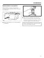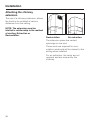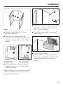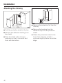
1
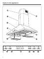
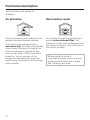
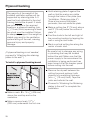
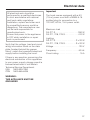
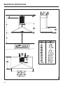
Operating and Installation
Instructions
Ventilation System
DA 211
DA 217-3
DA 218
DA 219-3
To prevent accidents
and machine damage,
read these instructions
before
installation or use.
UV
M.-Nr. 05 802 950
2
Contents
IMPORTANT SAFETY INSTRUCTIONS
Guide to the appliance
Functional description
Operation
Turning on the fan . . . . . . . . . . . . . . . . . . . . . . . . . . . . . . . . . . . . . . . . . . . . . . . . . 11
Selecting the power level. . . . . . . . . . . . . . . . . . . . . . . . . . . . . . . . . . . . . . . . . . . . 11
Delayed Shut Down . . . . . . . . . . . . . . . . . . . . . . . . . . . . . . . . . . . . . . . . . . . . . . . . 12
Turning off the fan . . . . . . . . . . . . . . . . . . . . . . . . . . . . . . . . . . . . . . . . . . . . . . . . . 12
Turning the lighting on/off . . . . . . . . . . . . . . . . . . . . . . . . . . . . . . . . . . . . . . . . . . . 12
Dimming the lighting . . . . . . . . . . . . . . . . . . . . . . . . . . . . . . . . . . . . . . . . . . . . . . . 12
Filter timers . . . . . . . . . . . . . . . . . . . . . . . . . . . . . . . . . . . . . . . . . . . . . . . . . . . . . . 13
Checking the filter timers . . . . . . . . . . . . . . . . . . . . . . . . . . . . . . . . . . . . . . . . . 13
Reprogramming the timers . . . . . . . . . . . . . . . . . . . . . . . . . . . . . . . . . . . . . . . . . . 14
Cleaning and Care
Cleaning the casing . . . . . . . . . . . . . . . . . . . . . . . . . . . . . . . . . . . . . . . . . . . . . . . . 16
Grease filters . . . . . . . . . . . . . . . . . . . . . . . . . . . . . . . . . . . . . . . . . . . . . . . . . . . . . 17
Active charcoal filters. . . . . . . . . . . . . . . . . . . . . . . . . . . . . . . . . . . . . . . . . . . . . . . 18
Changing the light bulb . . . . . . . . . . . . . . . . . . . . . . . . . . . . . . . . . . . . . . . . . . . . . 19
After Sales Service
Installation instructions
Caring for the environment
Installation accessories
Plywood backing
Electrical data
Appliance dimensions
Installation
Retaining plates . . . . . . . . . . . . . . . . . . . . . . . . . . . . . . . . . . . . . . . . . . . . . . . . . . . 32
Attaching the canopy. . . . . . . . . . . . . . . . . . . . . . . . . . . . . . . . . . . . . . . . . . . . . . . 34
Inserting the non-return flap . . . . . . . . . . . . . . . . . . . . . . . . . . . . . . . . . . . . . . . . . 35
Electrical connection . . . . . . . . . . . . . . . . . . . . . . . . . . . . . . . . . . . . . . . . . . . . . . . 36
Air extraction exhaust connection . . . . . . . . . . . . . . . . . . . . . . . . . . . . . . . . . . . . . 36
Recirculation connection . . . . . . . . . . . . . . . . . . . . . . . . . . . . . . . . . . . . . . . . . . . . 37
Attaching the chimney extension. . . . . . . . . . . . . . . . . . . . . . . . . . . . . . . . . . . . . . 38
Air extraction
Condensate trap . . . . . . . . . . . . . . . . . . . . . . . . . . . . . . . . . . . . . . . . . . . . . . . . . . 43
3
IMPORTANT SAFETY INSTRUCTIONS
Read these Operating Instructions carefully before installing or
using the Ventilation System.
This appliance is intended for
residential use only. Use the
appliance only for its intended
purpose. The manufacturer cannot
be held responsible for damages
caused by improper use of the
hood.
This appliance complies with current
safety requirements. Improper use of
the appliance can lead to personal
injury and material damage.
READ AND SAVE THESE
INSTRUCTIONS
CAUTION
For General Ventilating Use Only.
Do Not Use To Exhaust Hazardous
Or Explosive Materials And Vapors.
This appliance is designed to vent
cooking smoke and odors only.
Be certain your appliance is
properly installed and grounded by
a qualified technician.
To guarantee the electrical safety of this
appliance, continuity must exist
between the appliance and an effective
grounding system. It is imperative that
this basic safety requirement be met. If
there is any doubt, have the electrical
system of the house checked by a
qualified electrician. The manufacturer
can not be held responsible for
damages caused by the lack, or
inadequacy of, an effective grounding
system.
Before connecting the appliance to
the power supply make sure that
the voltage and frequency listed on the
data plate correspond with the
household electrical supply. This data
must correspond to prevent machine
damage. Consult a qualified electrician
if in doubt.
Installation work and repairs should
only be performed by a qualified
technician in accordance with all
applicable codes and standards.
Repairs and other work by unqualified
persons could be dangerous and the
manufacturer will not be held
responsible.
4
IMPORTANT SAFETY INSTRUCTIONS
This equipment is not designed for
maritime use or for use in mobile
installations such as caravans or
aircraft. However, under certain
conditions it may be possible for an
installation in these applications. Please
contact the nearest Miele dealer or the
Technical Service Department with
specific requirements.
Before servicing or cleaning the
unit, switch power off at the service
panel and lock the service
disconnecting means to prevent power
from being switched on accidentally.
When the service disconnecting means
can not be locked, securely fasten a
prominent warning device, such as a
tag, to the service panel.
Before discarding an old
appliance, unplug it from the
power supply and remove the power
cord and any doors to prevent hazards.
Use
Do not allow children to play with
or operate the appliance or its
controls. Supervise its use by the
elderly or infirm.
Be careful when preparing a
flambé beneath the hood.
Flames may be drawn up into the hood
by the suction or grease filters may
catch fire.
Never operate gas burners without
pots.
Do not leave cooking surfaces
unattended while in use.
Overheated food, oil and grease can
catch fire.
Do not use the hood without the
grease filters in place.
Clean the grease filters regularly.
Dirty filters are a fire hazard.
Do not use a steam cleaner to
clean the hood. Steam could
penetrate electrical components and
cause a short circuit.
In areas subject to infestation by
cockroaches or other pest, keep
the appliance and its surroundings
clean at all times. Any damage caused
by cockroaches or other pest will not
be covered under warranty.
Always turn on the hood when
using the cooktop to prevent
damage from condensation.
5
IMPORTANT SAFETY INSTRUCTIONS
, WARNING - TO REDUCE
THE RISK OF A RANGE TOP
GREASE FIRE:
Never leave surface units
unattended at high settings.
Boilovers cause smoking and greasy
spillovers may ignite. Heat oils slowly
on low or medium settings.
Always turn the hood “ON” when
cooking at high heat or when
cooking flaming foods.
Clean ventilating fans frequently.
Grease should not be allowed to
accumulate on the fan or filter.
Use proper pan size. Always use
cookware appropriate for the size
of the surface element.
, WARNING
TO REDUCE THE RISK OF INJURY
TO PERSONS IN THE EVENT OF A
RANGE TOP GREASE FIRE,
OBSERVE THE FOLLOWING:
SMOTHER FLAMES with a close
fitting lid, cookie sheet, or metal
tray, then turn off the burner.
BE CAREFUL TO PREVENT BURNS.
If the flames do not go out immediately,
EVACUATE AND CALL THE FIRE
DEPARTMENT.
NEVER PICK UP A FLAMING
PAN - You may be burned.
DO NOT USE WATER, including
wet dishcloths or towels - a violent
steam explosion will result.
Use an extinguisher
ONLY if:
– You know you have a Class ABC
extinguisher, and you already know
how to operate it.
– The fire is small and contained in the
area where it started.
– The fire department is being called.
– You can fight the fire with your back
to an exit.
6
IMPORTANT SAFETY INSTRUCTIONS
Installation
, WARNING
To reduce the risk of fire only
use metal ductwork.
When installing the hood, follow the
recommended minimum safety
distances between a Miele cooktop and
the hood:
– 22" (55 cm) above electric cooktops,
– 26" (65 cm) above gas cooktops,
– 26" (65 cm) above an open grill.
If local building codes require a greater
safety distance, follow their
requirement.
For non-Miele cooking appliances
maintain the safety distances
recommended by the appliance
manufacturer in their instructions.
If there is more than one appliance
beneath the hood and they have
different minimum safety distances
always select the greater distance.
Be careful not to damage hidden
electrical wiring or plumbing when
cutting or drilling into the wall or ceiling.
Any fittings, sealant, or materials
used to install the ductwork must
be made of approved non-flammable
materials.
Never connect an exhaust hood to
an active chimney, dryer vent, vent
flue, or room ventilating ductwork. Seek
professional advice before connecting
an exhaust hood vent to an existing,
inactive chimney or vent flue.
Ducted fans must always be
vented outdoors.
Make sure that the airflow in the
room is sufficient for combustion
and exhausting of all non-electric
heating appliances (water heaters, gas
cooktops, gas ovens, etc.), otherwise
backdrafts may occur. Follow the
heating manufacturer’s guidelines and
safety standards or those published by
the National Fire Protection Association
(NFPA), or the American Society for
Heating, Refrigeration and Air
Conditioning Engineers (ASHRAE).
If in doubt, consult an experienced
professional.
Do not use an extension cord to
connect the appliance to electricity.
Extension cords do not guarantee the
required safety of the appliance, (e.g.
danger of overheating).
Do not install this hood over
cooktops burning solid fuel.
7
Guide to the appliance
8
Guide to the appliance
a Chimney extension
m Grease filter button
b Chimney
The indicator above the grease filter
button lights when the grease filters
need to be cleaned. This button is also
used:
c Canopy
d Control panel
e Active charcoal filter
f Recirculation vent
g Overhead lighting
h Grease filters
i Light button
– to reset the grease filter timer after
cleaning the grease filters (see
"Cleaning and Care").
– to show how long the grease filters
have been in use (see "Operation /
Filter timers").
– to change the number of hours
counted by the grease filter timer
(see "Operation / Reprogramming the
filter timers").
n Charcoal filter button
j On/Off button
(used in recirculation mode only)
k Fan power level buttons
The indicator above the charcoal filter
button lights when the charcoal filters
need to be replaced.
Four fan speed selection
l Delayed Shut Down
This button activates the Delayed Shut
Down feature. The fan can be set to
turn off automatically after either 5 or 15
minutes.
This button is also used:
– to reset the charcoal filter timer after
changing the filters (see "Cleaning
and care").
– to show how long the charcoal filters
have been in use (see "Operation /
Filter timers")
– to change the number of hours
counted by the charcoal filter timer
(see "Operation / Reprogramming the
timers").
9
Functional description
The hood offers two modes of
operation:
Air extraction
Recirculation mode
The air is drawn in and cleaned by the
grease filters and directed outside.
Air is drawn through the grease filters
and an active charcoal filter. The
filtered air is then recirculated back into
the kitchen through a vent at the top of
the hood’s chimney.
The hood comes equipped with a
non-return flap. This flap automatically
closes when the hood is turned off so
that no exchange of outside air and
room air can occur. When the hood is
turned on, the air pressure of the
exhaust fan automatically opens the
flap blowing the inside air and cooking
odors outside.
10
Before using the hood in
recirculation mode, ensure that the
active charcoal filters are in place,
see "Cleaning and care".
Operation
Turning on the fan
Selecting the power level
^ Press the On/Off button.
^ Use the _ controls to select the
desired power level.
The fan runs at power level "2".
The On/Off indicator lights.
& =increases the fan speed
$ =decreases the fan speed
Level "1" to "3" (green indicators) are
usually sufficient for normal cooking.
Intensive setting
Level "4" (yellow indicator) should be
used for a short period when frying or
cooking food with a strong aroma.
Fan performance
The maximum air flow capacity is
625 cfm. Factors such as narrow duct
diameter and bends will affect this
value.
There will also be a slight decrease in
airflow for hoods operated in
recirculation mode due to the active
charcoal filter.
Level 1 operates at 40% capacity
Level 2 operates at 60% capacity
Level 3 operates at 80% capacity
Level 4 operates at 100% capacity
11
Operation
Delayed Shut Down
Turning the lighting on/off
If odors or smoke remain in the kitchen
after cooking has been completed, the
Delayed Shut Down feature can be
selected to allow the hood to continue
running for either 5 or 15 minutes.
The overhead lighting can be turned
on and off independently of the fan.
^ Press the light button briefly to turn
on the lighting.
^ Press the Delayed Shut Down button
while the fan is still running.
The light button indicator illuminates.
Press once = 5 minute delay
(left indicator lights)
Press twice = 15 minute delay
(right indicator lights)
The light button indicator will go out.
To cancel the Delayed Shut Down
feature press the button again.
Turning off the fan
^ Press the On/Off button to turn the
fan off.
The indicator goes out.
Automatic Safety Shut Off
The fan will turn off automatically 10
hours after the last button was activated.
The lighting however will remain on.
^ Press the On/Off button to turn the
fan back on again.
12
^ Press the light button briefly again to
turn off the lighting.
Dimming the lighting
The brightness of the lighting can be
adjusted.
^ While the lighting is turned on, press
the light button.
The lighting will dim until the button is
released.
^ If the button is pressed again, the
lighting will brighten until the button is
released.
If the button is pressed continuously,
the light will cycle between bright and
dark.
^ Press the light button again to turn off
the lighting.
Operation
Filter timers
Checking the filter timers
Grease filters
To check the percentage of time
already used:
A timer monitors the hours of fan
operation. The indicator for the grease
filter will light after 30 hours of
operation. The grease filters must then
be cleaned.
After the grease filters have been
cleaned and put in place, the grease
filter timer must be reset.
^ To do this, press the grease filter
button for about 3 seconds.
^ Press the On/Off button to turn the
fan on.
^ Press the grease or charcoal filter
button.
The indicator will go out.
Charcoal filters
The timer for the charcoal filter is not
preset. Please program this timer, see
"Operation/Reprogramming the
charcoal filter timer".
The charcoal filter indicator will light
once the selected time has elapsed.
The charcoal filters must then be
replaced and the charcoal filter timer
must be reset.
The number of flashing _ indicators
show the percentage of programmed
hours that have been used.
1 indicator
2 indicators
3 indicators
4 indicators
=
=
=
=
less than 25 %
less than 50 %
less than 75 %
less than 100 %
This information will remain stored in
memory in the event of a power failure.
^ To do this, press the charcoal filter
button for about 3 seconds.
The indicator will go out.
13
Operation
Reprogramming the timers
The grease filter timer is preset to 30
hours. This time can be lengthened or
shortened to 20, 30, 40 or 50 hours.
– A time of 20 hours should be
programmed in kitchens with
frequent pan or deep frying.
– A time of 20 hours should also be
programmed if the kitchen is only
used occasionally. Otherwise grease
which has accumulated over a long
period of time will harden on the
filters making cleaning more difficult.
The indicator for the grease filter and
one of the _ indicators will flash.
The lit indicator shows the programmed
time:
1st indicator from the left
2nd indicator from the left
3rd indicator from the left
4th indicator from the left
=
=
=
=
20 hours
30 hours
40 hours
50 hours
^ Use the $ or & button to select the
desired time.
Reprogramming the grease filter
timer
^ Press the On/Off button to turn off the
fan.
^ Press the Delayed Shut Down and
grease filter buttons at the same time.
14
^ Store the selection by pressing the
grease filter button.
If the procedure is not stored within
4 minutes of programming, the hood
will automatically default to the "old"
data.
Operation
Reprogramming the charcoal filter
timer
The active charcoal filter can only be
used in recirculation mode and can not
be used to exhaust fumes.
The charcoal filter timer is not preset.
Before using the hood in recirculation
mode, the charcoal filter timer must be
programmed.
^ Turn off the fan using the On/Off
button.
^ Press the Delayed Shut Down and
Charcoal Filter buttons at the same
time.
The indicator for the charcoal filter and
one of the _ indicators will flash.
The lit indicator shows the programmed
time:
1st indicator from the left
2nd indicator from the left
3rd indicator from the left
4th indicator from the left
=
=
=
=
20 hours
30 hours
40 hours
50 hours
^ Use the $ or & button to select the
desired time.
^ Store the selection by pressing the
charcoal filter button.
If the procedure is not stored within
4 minutes of programming, the hood
will automatically default to the "old"
data.
15
Cleaning and Care
Before cleaning or servicing the
hood, disconnect it from the power
supply by either removing the fuse,
unplugging it from the outlet or
manually "tripping" the circuit
breaker.
Cleaning the casing
,Never use abrasive cleaners,
scouring pads, steel wool or caustic
(oven) cleaners on the hood. They
will damage the surface.
^ All external surfaces and controls can
be cleaned with warm water and
liquid dish soap applied with a soft
sponge.
^ Wipe dry using a soft cloth.
Do not use too much water when
cleaning the controls. Water could
penetrate into the electronics and
cause damage.
Avoid:
– cleaning agents containing soda,
acids or chlorides,
– abrasive cleaning agents e.g.
powder or cream cleansers,
– abrasive sponges, e.g. pot scourers
or sponges which have been
previously used with abrasive
cleaning agents.
These will damage the surface.
16
Stainless steel
Stainless steel surfaces can be cleaned
using a non-abrasive stainless steel
cleaner.
To help prevent resoiling, a conditioner
for stainless steel can also be used.
Apply sparingly with even pressure.
Stainless steel colored controls
These controls may become
discolored or damaged if not
cleaned regularly.
Do not use a stainless steel cleaner
on these controls.
Cleaning and Care
Grease filters
The reusable metal grease filters
remove solid particles from the vented
kitchen air (grease, dust, etc).
The grease filters should be cleaned
every 3 - 4 weeks or whenever the
grease filter indicator lights.
A dirty filter is a fire hazard.
Depending on the detergent,
cleaning the grease filters in a
dishwasher may cause permanent
discoloration of the filter surface.
Performance of the filter will not be
affected by this discoloration.
^ After cleaning, the filters can be
placed on a towel to air dry.
^ While the filters are removed, clean
any dirt or grease from the filter
casing to prevent the risk of fire.
When putting the grease filters back
make sure that the locking clips are
visible facing down towards the
cooking surface.
If a filter is incorrectly installed, insert a
small screwdriver into the slit along its
edge to disengage it from the casing.
^ To remove the grease filters press the
locking clips in towards the middle of
the filter. Holding carefully, lower and
remove the filter.
^ Clean the filters
- by hand: use a scrub brush in
warm water with a mild detergent.
- in a dishwasher: place the filters in
the lower basket, making sure that
the spray arm is not blocked.
^ After returning the grease filters,
press the grease filter button for
3 seconds to reset the timer.
The indicator light will go out.
^ If the grease filters are cleaned
before the timer has reached its
maximum, the grease filter button
should be pressed for 6 seconds to
reset the counter to zero.
17
Cleaning and Care
Active charcoal filters
In recirculation mode two active
charcoal filters must be used in
addition to the grease filters. The
charcoal filters are designed to absorb
cooking odors.
Replacement active charcoal filters
can be ordered from the
Miele Technical Service Department.
USA 1-800-999-1360
CDN 1-800-565-6435
Please quote part # 03 284 681.
^ Remove the grease filters to access
the charcoal filters.
Follow the instructions supplied with the
active charcoal filters.
Replace the active charcoal filters when
the charcoal filter indicator lights.
Replace the filters at least every 6
months or when they no longer absorb
odors efficiently.
18
^ After replacing the charcoal filters,
press and hold the charcoal filter
button for about 3 seconds to reset
the charcoal filter timer.
The indicator light will go out.
^ If the charcoal filters are replaced
before the timer has reached its
maximum, the charcoal filter button
should be pressed for 6 seconds to
reset the counter to zero.
Cleaning and Care
Changing the light bulb
Before changing the light bulbs,
disconnect the hood from the power
supply by either removing the fuse,
unplugging it, or manually "tripping"
the circuit breaker.
When in use halogen bulbs become
extremely hot, and they can burn
your hands. Do not attempt to
change the bulbs until they have
had sufficient time to cool down.
Do not touch the bulb surface.
Fingerprints or body oils deposited
on the bulb will decrease the life of
the bulb.
Follow the bulb manufacturer’s
instructions.
^ To change the halogen bulb first
remove the lamp cover, a.
^ Pull the bulb, b, out of its socket and
replace with a new one.
^ Return the lamp cover, a.
Never use the lighting without the
lamp cover, a, in place. The glass is
specially made to filter harmful light
rays.
19
After Sales Service
In the event of a fault which you can not
correct yourself please contact:
– Your Miele Dealer
or
– The Miele Technical Service
Department
USA
1-800-999-1360
[email protected]
CDN
1-800-565-6435
[email protected]
When contacting the Technical Service
Department, please quote the model
and serial number of your appliance.
These are shown on the data plate
which is visible when the grease filter is
removed.
20
Installation Instructions
22
Caring for the environment
Disposal of packing material
Disposal of an old appliance
The cardboard box and packing
materials protect the appliance during
shipping. They have been designed to
be biodegradable and recyclable.
Please recycle.
Old appliances may contain materials
that can be recycled. Please contact
your local recycling authority about the
possibility of recycling these materials.
To prevent suffocation of children,
ensure that any plastic wrappings,
bags etc. are disposed of safely and
kept out of their reach.
Before discarding an old hood,
unplug it from the outlet and cut off
its power cord to prevent hazards.
23
Installation accessories
24
Installation accessories
a 2 recirculation vents
(recirculation mode only)
b 2 protective shields
prevent scratches to the chimney
during installation.
c 1 protective shield
prevents scratches from the canopy
during installation.
d 1 diverter
(recirculation mode only)
12 large headed screws 5 x 40 mm
for securing the retaining plates and the
canopy.
(S8 wall anchors included in the
packaging are not for use in USA /
CDN.)
e 1 flex hose for connecting the
diverter to the exhaust connection.
f 2 hose clips for securing the
ducting.
2 M 6 locking nuts for securing the
motor assembly.
g 1 reducing collar
for use with 5" (125 mm) exhaust
ducting.
h 1 non-return flap for vented air
extraction only.
4 screws 3.9 x 7.5 mm for securing the
chimney and the chimney extension
i Upper retaining plate B secures
the chimney extension.
j Middle retaining plate C for
additional stability of the chimney.
k Lower retaining plate A secures
the canopy and motor assembly.
CAUTION:
During the installation process
please be careful of sharp edges
that can cause harm.
25
Plywood backing
The majority of the weight of the
installed ventilation system will be
supported by retaining plate A. It
must be firmly attached to the stud
framing behind the drywall. If studs
are not available in the required
locations, a plywood backing (min.
1
/2" (13 mm) thick) spanning at least
two studs must be installed. Failure
to adequately support the weight as
stated may result in the ventilation
system falling off the wall, causing
personal injury and property
damage.
(If plywood backing is not needed,
proceed to "Attaching the retaining
plates to the wall." )
To install a plywood backing board
^ Hold retaining plate A against the
wall so that the marks are visible
through the holes of the plate (see
"Installation / Retaining plate A").
Draw a line around the plate’s
perimeter, then set aside the plate.
^ Make a cutting line 3" (76 mm) above
and 3" (76 mm) below the outline of
plate "A".
^ Find the studs to the left and right of
the mounting location by tapping the
wall or using a stud finder.
^ Mark a vertical cutting line along the
center of each stud.
Be careful not to damage any wiring
or plumbing that may be located
behind the wall. Make sure that the
power supply to the area where this
installation is being performed has
been turned off at the breaker panel
before cutting into the wall.
^ Remove the drywall between the
cutting lines and replace it with
plywood of a matching thickness
(min. 1/2" (13 mm) thick). Tape the
joints and refinish the wall.
^ Proceed to "Attaching the Retaining
plates to the wall" to complete the
installation.
^ Make a mark, S + 16 3/4" (425 mm)
above the cooktop and on the
centerline.
^ Make a second mark 12 3/4 "
(324 mm) underneath the first one.
26
Electrical data
All electrical work should be
performed by a qualified electrician
in strict accordance with national
and local safety regulations.
Installation, repairs and other work
by unqualified persons could be
dangerous. The manufacturer can
not be held responsible for
unauthorized work.
Ensure that power to the appliance
is OFF while installation or repair
work is performed.
Verify that the voltage, load and circuit
rating information found on the data
plate (located behind the grease
filters), match the household electrical
supply before installing the hood.
Important
The hood comes equipped with a 5 ft
(1.5 m) power cord with a NEMA 5-15
molded plug for connection to a
120 VAC, 60 Hz, 15 A power outlet.
Maximum load
DA 217-3 . . . . . . . . . . . . . . . . . . . 390 W
DA 211, 218, 219-3 . . . . . . . . . . . 410 W
Lighting
DA 217-3 . . . . . . . . . . . . . . . . . 2 x 20 W
DA 211, 218, 219-3 . . . . . . . . . 3 x 20 W
Voltage . . . . . . . . . . . . . . . . . . . . . 120 V
Frequency . . . . . . . . . . . . . . . . . . 60 Hz
Circuit rating. . . . . . . . . . . . . . . . . . 15 A
If there is any question concerning the
electrical connection of this appliance
to your power supply, please consult a
licensed electrician or call Miele’s
Technical Service Department.
USA 1-800-999-1360
CDN 1-800-565-6435
WARNING:
THIS APPLIANCE MUST BE
GROUNDED
27
Appliance dimensions
28
Appliance dimensions
Do not install this exhaust hood over
cooktops burning solid fuel.
When installing the hood, make sure
that the following minimum
distance (S) between the top of a
Miele cooking surface and the
bottom of the hood is:
- 22" (55 cm) above electric cooktops
- 26" (65 cm) above gas cooktops
- 26" (65 cm) above an open grill
Standard unit height H:
DA 211
Extraction. . . . . . . . . . . . 29 1/8" - 38 9/16"
. . . . . . . . . . . . . . . . . . . (740 - 980) mm
Recirculation . . . . . . . 32 11/16" - 41 15/16"
. . . . . . . . . . . . . . . . . . (830 - 1065 mm)
DA 217-3
Extraction . . . . . . . . . . . . . 28" * - 37 3/8"
. . . . . . . . . . . . . . . . . . . (710* - 950) mm
Recirculation . . . . . . . . . . 31 1/2" - 40 3/4"
. . . . . . . . . . . . . . . . . . (800 - 1035 mm)
For non-Miele cooking appliances
maintain the safety distances
recommended by the cooktop
manufacturer in their installation and
operating instructions.
DA 218
Extraction . . . . . . . . . . . . 28 1/8" - 37 5/8"
. . . . . . . . . . . . . . . . . . . (715 - 955) mm
Recirculation . . . . . . . 31 11/16" - 40 15/16"
. . . . . . . . . . . . . . . . . . (805 - 1040 mm)
If there is more than one appliance
beneath the hood and they have
different minimum safety distances
always select the greater distance.
DA 219-3
Extraction. . . . . . . . . . . . 28 3/4" - 38 3/16"
. . . . . . . . . . . . . . . . . . . (730 - 970 mm)
Recirculation . . . . . . . . 32 5/16" - 41 9/16"
. . . . . . . . . . . . . . . . . . (820 - 1055 mm)
See "Warning and Safety
instructions" for further information.
26" (65 cm) is recommended for all
installations to allow for optimum work
space under the hood.
Read the entire installation procedures
and determine height (S) before
beginning the installation. Installation
producers differ depending on the
model and venting method.
If the hood is fitted flush to the ceiling
make sure that the remaining distance
to the ceiling is not greater or less than
appliance height H.
* With air extraction to the rear through
a wall the total height must be at least
31 1/8" (790 mm).
To fit the chimney, distance A between
the top of the chimney and the ceiling
must be at least 7/8" (20 mm).
Cut out area in wall or ceiling for
entrance of 6" (150 mm)
ductwork or 5" (125 mm)
ductwork with a reducing collar.
29
Appliance dimensions
If the standard unit height H is not suitable to the kitchen’s ceiling height, longer
optional chimney extensions are available from your Miele dealer or Miele’s
Technical Service Department.
DA 211
Extraction
1
Recirculation
9
Standard unit H
29 /8" - 38 /16"
740 mm - 980 mm
32 11/16" - 41 15/16"
830 mm - 1065 mm
DATK 217/219 605
38 9/16" - 48"
980 mm - 1220 mm
42" - 51 3/16"
1066 mm - 1300 mm
DATK 217/219 840
48" - 57 1/2 "
1220 mm - 1460 mm
51 3/16" - 60 1/2"
1300 mm - 1536 mm
DA 217-3
Extraction
Recirculation
Standard unit H
28" - 37 /8"
710 mm - 950 mm
31 1/2" - 40 3/4"
800 mm - 1035 mm
DATK 217/219 605
37 3/16" - 46 7/16"
945 mm - 1180 mm
40 3/4" - 50"
1035 mm - 1270 mm
DATK 217/219 840
46 7/16 " - 55 11/16 "
1180 mm - 1414 mm
50" - 59 1/4"
1270 mm - 1505 mm
30
3
Appliance dimensions
DA 218
Extraction
Recirculation
Standard unit H
28 1/8" - 37 5/8"
715 mm - 955 mm
31 11/16" - 40 15/16"
805 mm - 1040 mm
DATK 217/219 605
37 5/8" - 47"
955 mm - 1195 mm
41" - 50 3/16"
1041 mm - 1275 mm
DATK 217/219 840
47" - 56 1/2 "
1195 mm - 1435 mm
50 3/16 - 59 1/2"
1275 mm - 1511 mm
DA 219-3
Extraction
Recirculation
Standard unit H
28 3/4" - 38 3/16"
730 mm - 970 mm
32 5/16" - 41 9/16"
820 mm - 1055 mm
DATK 217/219 605
38 3/16" - 47 5/8"
970 mm - 1210 mm
41 9/16" - 50 13/16"
1056 mm - 1290 mm
DATK 217/219 840
47 5/8 " - 57 1/16 "
1210 mm - 1450 mm
50 13/16" - 60 1/16"
1290 mm - 1526 mm
31
Installation
Retaining plates
The ventilation system will be mounted
to the wall through the use of retaining
plates. Plate A is installed first,
followed by plate B. Plate C should only
be used if the distance between plate A
and plate B is greater than 14 3/8"
(365 mm).
32
Attaching the retaining plates
to the wall
^ Before fitting the retaining plate draw
a vertical line centrally above the
cooktop on the rear wall.
^ Mark measurement S from the
cooktop surface upwards (see
"Appliance dimensions"). This marks
the height of the lower rim of the
hood.
Installation
Retaining plate A
^ Drill two 1/8" (3 mm) holes, one at S +
4" (100 mm) and one at S + 16 3/4"
(425 mm) on the center line for the
retaining plate (see "Appliance
dimensions").
^ Lightly secure retaining plate A into
position using 5 x 40 mm screws
through the two holes and use the
notches to align with the center line.
^ Drill 4 more 1/8" (3 mm) holes through
the now fitted retaining plate.
^ Screw two 5 x 40 mm screws into the
upper two holes.
Retaining plate B
^ Hold retaining plate B to the wall and
push up until it is directly below the
ceiling. Use the notches and the
center line to align it horizontally.
Mark the 2 drill holes on the wall.
^ Drill two 1/8" (3 mm) holes into the
wall.
^ Secure the retaining plate with two
5 x 40 mm screws.
33
Installation
Retaining plate C
Retaining plate C should only be used if
dimension Y is greater than 14 3/8"
(365 mm.) It provides additional
stability for the chimney extension.
Attaching the canopy
^ Hang the canopy on the angled
brackets on retaining plate A.
^ At a maximum distance of 14 3/8"
(365 mm) from the ceiling hold
retaining plate C against the wall and
use the notches to align it with the
center line. Mark the two drill holes.
^ Drill two 1/8" (3 mm) holes into the
wall.
^ Secure retaining plate C with two
5 x 40 mm screws.
^ Secure the canopy with 5 x 40 mm
screws into each drilled hole.
34
Installation
Inserting the non-return flap
^ Air extraction:
If a non-return flap is not present in
the venting system, the non-return
flap supplied must be fitted into the
exhaust connection on the motor. The
flaps must open upwards.
Attaching the motor assembly
^ First loosely screw the two locking
nuts onto the threaded bolts on
retaining plate A.
Leave a gap of 1/8" (3 mm) for
hanging the motor on.
^ The hood is designed for 6" (150 mm)
exhaust ducting. If 5" (125 mm)
exhaust ducting is used the reducing
collar must be fitted into the exhaust
connection on the motor (see "Air
extraction").
^ Recirculation mode:
The non-return flap is not required.
^ Fit the motor assembly onto the
hooks on retaining plate A and slide
down behind the nuts.
^ Tighten the nuts.
35
Installation
Electrical connection
Before connecting the appliance
read the "Warning and Safety
Instructions" and the "Electrical data"
sections.
Air extraction exhaust
connection
^ Connect the ductwork to the exhaust
connection using whatever means
are appropriate for the type of
ductwork being installed (hose
clamp, duct tape, etc.)
^ Plug the 2 connectors on the canopy
into the corresponding receptacles
left and right of the motor assembly.
Insert the 4 prong connector into the
receptacle left of the motor
assembly.
Insert the 6 prong connector into the
receptacle right of the motor
assembly.
^ Secure the cords with the ties, as
shown above.
^ Plug in the power cord.
36
^ Direct the duct through the back wall
or the ceiling.
^ See "Air extraction" for further details.
Installation
Recirculation connection
Recirculation mode is used when
venting to the outside of the building is
not possible.
^ Slip the hose clamps over the flex
hose onto the diverter and the motor
assembly exhaust connection. Once
in place, tighten the hose clamps.
^ Slide the diverter on to the brackets
of plate B.
Active charcoal filters must be used
in the recirculation mode.
37
Installation
Attaching the chimney
extension
The use of a chimney extension, allows
the hood to be installed at various
distances from the ceiling.
NOTE: The extension must be
intalled in relationship to the method
of venting; Extraction or
Recirculation.
Recirculation
Air extraction
The extension piece has vented
openings on one end.
These vents are required for recirculation mode and will be closest to the
ceiling when installed.
For air extraction, the vents are not
required and are covered by the
chimney.
38
Installation
^ Screw the extension piece firmly to
the upper retaining plate using two
3.9 x 7.5 mm screws.
^ Remove the protective foil from
chimney extension.
^ Cover the screws with the supplied
cap covers.
^ Bend the top hanging tabs 45°
inwards. This will make installing the
extension easier. Be careful of sharp
edges.
^ Only for recirculation:
With the slats pointing downwards,
install the recirculation vents through
the extension piece and into the
diverter.
Recirculation
Air extraction
^ Pull the chimney extension slightly
outwards and snap over the upper
retaining plate B.
When installing for recirculation, ensure
that the vents are positioned so they
line up with the diverter.
39
Installation
Attaching the chimney
^ Remove the protective foil from the
chimney.
^ Fold the protective shield at the top.
^ Remove the adhesive backing from
the shield.
^ Stick the shield to the chimney
extension so that it is smooth and
flush with the bottom.
40
^ Remove the backing from the
adhesive strips on the protective
shield.
^ Attach the protective shield to the
front of the chimney so that it
protrudes slightly below the bottom
edge.
Installation
^ Secure the chimney to reatining plate
A on both sides with two
3.9 x 7.5 mm screws.
^ Remove the protective foil from the
canopy.
^ Pull the chimney apart slightly and
slide it over the chimney extension.
Do this carefully to prevent scatching
the two pieces.
^ Slide the chimney down aligning its
lower screw holes with those on the
side of retaining plate A.
^ Remove the protective shields.
^ Before using the appliance remove
the grease filter and remove the
protective foil from the filter frame.
Return the filter.
If the chimney is not tall enough an
optional chimney extension can be
ordered. See "Installation /
Appliance dimensions".
41
Air extraction
,WARNING
Danger of toxic fumes.
Gas cooking appliances release
carbon monoxide that can be
harmful or fatal if inhaled.
The exhaust gases extracted by
the hood should be vented
outside of the building only.
Do not terminate the exhaust
ducts in attics, garages,
crawlspaces, etc.
To reduce the risk of fire, only use
metal ductwork.
Please read and follow the
"IMPORTANT SAFETY
INSTRUCTIONS" to reduce the risk of
personal injury. Follow all local building
codes when installing the hood.
42
Exhaust ducting and connections
– The ducting should be as short and
straight as possible, and the number
of sharp bends should be minimized.
– For most efficient air extraction, the
diameter of the ductwork should not
be less than 6" (150 mm). Use of flat
ducts also reduces the air extraction
efficiency.
– Noise levels of the hood will increase
if flat ducts or round ducts of less
than 6" (150 mm) in diameter are
used.
– Use smooth or flexible pipes made
from approved non-flammable
materials for exhaust ducting.
– Where the ductwork is horizontal, it
must slope away from the hood at
least 1/8" per foot (1cm per meter) to
prevent condensation dripping into
the appliance.
– If the exhaust is ducted through an
outside wall, a Miele Telescopic Wall
Vent can be used.
Air extraction
Condensate trap
Important:
If the ductwork runs through rooms,
ceilings, garages, etc. where
temperature variations exist, it may
need to be insulated to reduce
condensation. In some cases, a
condensate trap may also be required
to collect and evaporate any
condensate which may occur.
When installing a condensate trap,
ensure that it is positioned vertically
and if possible directly above the
exhaust outlet.
– If the exhaust is ducted into an
inactive flue, the air must be expelled
parallel to the flow direction of the
flue.
Never connect an exhaust hood to
an active chimney, dryer vent, vent
flue, or room venting ductwork. Seek
professional advice before
connecting an exhaust hood vent to
an existing, inactive chimney or vent
flue.
43
Alteration rights reserved / 1703
This bio-friendly paper was bleached without the use of chlorine.
M.-Nr. 05 802 950 / 00