1
UPITERU
MVT-7100
Wi I
and Hand Held Receiver
Operating Instructions
I h M V I I I on
~ ~supplied
,,,,,, .,,,,
(
l '!Ill I'
.\'/II If /
''"'
''"'''''
I III/I 1/l 'lillllf//)()k/et
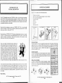
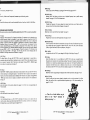
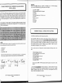
Please look after the packaging you receive your YUPITERU MVT -7100 in, it may be needed
should it be necessary to return the unit to the place of purchase and you may also find it of value
should you ever 'trade in' or sell your MVT-7100.
(
M i l l ~ , ,.
~
\
'"
12 volt DC Adaptor
Ai ht jiiOI
Carry Strap
I
,,,
l'h 11u:nd1 •uppli ·d urc no t factory charged and may require a good 15 hour charge with the charger
N11ppl icd wl11l th · set is switched otT before they can be used . You will find that rechargeable
hn li '' N will Hiv litr belt er results if every now and again you fully discharge them. Try to avoid
tt uxiuf( Nicnd batt erios purchased at different times together, you may not get the maximun
p d b 11nuuco avuilublc if you do.
'J'h 111 ·nwry bac kup battery will retain frequencies stored in memory
li u nhu111 7 days should the nicads loose there charge or are removed.
'J'hi11 bnck 11p batt ery will be charged each time an external 12v source is
l'Otlltcl:l •d l(>r at least one hour.
th su ppl ied batteries with either rechargeable or alkaline
the battery cover and place the four batteries into the
' ''"' uf' 1h 1c · ·ivor ensuring that the correct polarity is observed and
H1p in1 11 l i.11 h111t ' I y \lOVCT.
1'11 111p ilhl<l
illlll•1!1•
I hope you find this instruction hooklet easy to follow, whilst some parts may seem /on~ winded I
have tried to explain the procedures in a manner which will allow users of varyin~ 'scanner' knowhow ?et the hest out of the MV7~7100 as quickly as possihle. For the experienced user some
explanations may seem tmeccessary and drawn out hut we know from experience that no maller how
hard )'Oil try you camwt answer everybodies questiOIIS. Any comments (or corrections ') would be
most welcome.
.~if':,
Happy Sanning.
MVf-7100 Operating Instructions 1.0 ©)aviation January 1993.
Page2
Belt Clip
~
p
i ) Jj • •. ,.
Those of you familiar with English instructions translated and
printed in Japan will know that in most cases they leave a lot to
be desired (after saying that their English is better than my
Japanese !), we hope you will find these instructions far more
comprehensive and understandable. Please read them carefully.
Compared to some receivers the MVT-7100 is one ofthe easier
ones to program and operate, (who said that !) however we do
appreciate that some of the operations can be "complicated",
especially to the newcomer and many faults which owners
report are operations that have been carried out incorrectly.
Should your MVT-7100 not do what it apparently should,
please try again reading the instructions slowly before calling
your dealer. Owners of previous Yupiteru models should have littl e trouble in operating this new set.
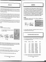
with the following accessories:-
I Nil 11d All .wze batteries
A/d/11' ('llwt•r ·''"f'I''Y rmit!Ballery Charger (12 valls DC, 200mA)
I It ' I mul wltlr t·r~;ar lighter plug
/, •/ ,1\i 'fljill' rllltlllllt£1
The MVT-7100 handheld receiver from YUPITERU is a follow on from their previous outstanding
models. The MVT-7100 has continuous frequency coverage from I OOKHz to 1650MHz, with modes
of AM, Narrow FM, Wide FM, Upper Side Band (USB) & Lower Side Band (LSB). There are I 000
memory channels provided in I 0 banks of I 00 into which you can store frequency & mode while I 0
programmable search banks are also available.
Please look after your YUPITERU MVT-7100 with care, avoid getting the unit wet (try not to use it
in the bath - it is has been known to have submerged receivers arrive for repair I) and also direct
sunlight, in particular car dash boards. Taking care of your receiver will also maintain its value
should you ever wish to sell or part exchange the set.
II
SUPPLIED ACCESSORIES
YUPITERU MVT-7100
GENERAL DESCRIPTION
1outov
v
MVf-7100 Operating Instructions 1.0 ©)aviation January 1993.
Page3
I
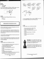
~ONTROLS
II
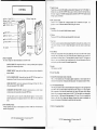
) . , IJil<' l li ( ;<iutrol
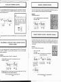
1'11111 d 1\JIIy anti-clockwise the squelch is off and constant background "noise" will be heard. To
nflomnhl th noi se and allow the MVT-7100 to scan or search tum clockwise until such time as
tht " tliil ~ " disappears. The further clockwise the less sensitive the MVT-7100 becomes & only
tt i' IIKI"' ~ ' K " t~ l s wi ll be heard.
0 Rotary Tuning Dial-------------------,
@ Power On/Off & VollJile ----;=::::::::=c:s;
@ Squelch Control----- - ' ~---...-uonn"
0 BNC Antenna Jack---------
e Lamp
•I, li N( · Auh·nun Socket
I h MV 1'-7 100 is supplied with I telescopic antenna which is connected at this point.
pu 1hlo 1o '(lllncct an alternative antenna to the set using this connector.
, ll udd Jthl
I h11 hn ·klifJ.hl wi ll only remain lit whilst the button is pressed.
Switch --------f"I(J
411 External ---&\\
Speaker
r•• Muu
f' Monitor Switch -------+'l!>"'t
eKey Lock
@
It is
l'r ••
tur·
~ lll fl,
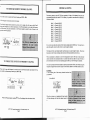
tho MONI key effectively opens the squelch fully while pressed.
Switch -------+~
-Reset Switch
7. I' ;• l .o1d1
Tu p1 ov ' "' n ·cid cntal operations the keypad can be disabled by moving Key lock switch up to the
"u n" posi ri on showi ng a red dot. To restore the keypad the key lock switch has moved back
down .
------i~
~
€l Speaker
External - - ---f--'\ill
12v s upply
8. Reset IJutton.
Pressi ng thi s recessed button with a fine pointed object will result in the MVT-7100's Central
Processor Uni t (C PU) being re-set. This will clear all memory channels and also re-set the 10
scM h banks to the factory pre-set. This button should be pressed if the MVT-7100 appears to
lock nr or not accep t frequencies, bear in mind however that all stored information will be lost
so il may b · 11 good idea to record all the stored frequencies first.
®Battery - - ---"'<!dt-Cover
1. Rotary Tuning Dial
The rotary tuning knob has several functions on the MVT-7100:-
MANUAL MODE: The /lining knob allows you to tune up or down from the displayed
frequency in the increment steps chosen
?. Spo· ukt·r
S If l:xplunarory we think !
MEMORY MODE: Turning the knob allows you to mm·e up or down through the
memory channels.
10.
SCAN & SEARCH MODE: Turning the knob when the W ·T -7100 has stopped
transmission will restart the scan or search in the direction chosen
II. Enrpiece/Externnl Speaker socket. 3.5mm Jack
This a a 3.5mm standard socket. The earpiece supplied, headphones or external speaker may be
co nnected to this socket but will disconnect the main speaker. The impedance should be 8 Ohms.
011
a
MODE SELECTION: Usedfor the selection of AM, Narrow rM, Wide FM, USB or
LSB when rotated after FUNC +MODE
INCREMENT STEP SELECTION: Used for the selection of any one of the various
increme/11 steps when rotated after pressing the STEP hull on.
The rotary knob is also be used for scrollin~ throu~h fr?tfueucies entered illlo the
Search Pass facility and in conjunction with the CIAC key when correct111g a keyboard
elllry.
2. Power On/OfT & Volume
Turning clockwise turns the set on and increases the volume. Turned full y anti-clockwise the
receiver will be turned off.
MVf-7100 Operating Instructions 1.0 (I )aviation J:onual)' 1993.
Pagc4
llrry Str:IJl !look
12. 12 Volt External Power Jack
The centre pin is positive. Used to connect the mains power charging unit or DC cigar lighter lead
to the MVT-7100. Care must be taken to ensure the correct DC voltage ( 11-1 5 volts) is applied.
When connected to this socket the external source will charge the internal nickel cadmium
bnucries. Do not connect an external source to the MVT-7100 when alkaline (non rechargeable)
bntl rics are fitt ed. A full charge. will take approximately 12-15 hours. Try not to overcharge the
bull ·roes. while this will not cause major damage, prolonged and constant overcharging can
im:rc11sc the temperature of the batteries to a point where they may explode.
IJ .
ll~tllc:ry
Compartment Cover
MVf-7100 Operating lnsrructions 1.0 <!:> JaYiation January 1993.
Page 5
II
LCD DISPLAY
II
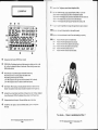
0
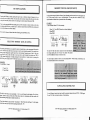
I ),-,,uu nl Point. The figures to the left indicate MegaHertz (MHz).
I h '111ui n' display shows the currently selected frequency in MHz. As you enter
hutut ·lnumbcrs or bank numbers these will also be temporarily displayed.
" 1.1 . I' A ' S " will·be displayed when all memory banks/channels have been locked out.
" 11:JTm ·" will be displayed when an incorrect entry has been attempted.
" I I I 1.1," will be displayed when the Frequency Pass facility for searching is full.
i
0
tJl)
1234567890
PG M- SCAN SEARCH
11
~•·wt l ·nt Signal Strength Meter, the stronger the signal the more segments disp layed.
0 0 lnd tl:ntcs when signal is being received or when squelch is opened.
0
I ),. piny ·<I
0
Displayed when the
Displayed when the
/'/(/
Displayed when the
/) 1•:1.11 y Displayed when the
111-:1-.'1 ' Displayed when the
11IT
Displayed when the
when batteries become low and will soon need recharging or replacing.
S. JI '/·.'
SA II '
0
Displayed each time Function (FUN C) Key is pressed
6
STEP & KHz will be displayed together with the increment step display just below to the
left. It will only be displayed in Manual or Search mode. When selecting increment steps
STEP & KHz will flash.
C)
When in Manual or Search Mode displays the selected increment step.
When in Memory Mode or Scanning displays the channel number.
When selecting increment steps these will flash .
A "P" will be displayed to the right when the Priority channel (1000) is selected)
A"P" will be displayed to the left to indicate a Search Pass frequency.
0
Bank Numbers. When Scanning or Searching indicates which bank or banks have been
selected. These numbers will also indiacte the number of channels in the Program Scan.
0
Indicates if the set is Scan Mode, Search Mode' or Program Scan mode. Nothing is displayed
when in Manual mode. PGM will be displayed with any channel in the Program Scan.
0
Displays selected mode of reception. The mode will flash when in Mode Scan.
&
Decimal Point. The 3 figures to the left are KiloHertz (KHz), figures to the right are
Hertz (Hz).
receiver is in Standby Mode.
Skip facility has been activated.
Priority channel has been activated.
Delay facility has been activated.
Keyboard sound is on.
Attenuator has been selected.
t'V"r ';,v,~.:Y:5'd0
00
I
~
L -·j../\ \.1.1
/1'?}3J..Id)1"
You mean .... I have to understand all this ?
MVf-7100
Operating Instructions 1.0 O Javiation January 1993.
Page6
MVf-7100
Operating Instructions 1.0 © Javiation January 1993.
Page 7
SCAN
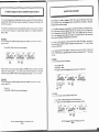
KEYPAD CONTROLS
l'r r in!( 1his key once starts the MVT-7100 scanning the memory channels. Pressing whilst the
'""' is ~ 'llltning will stop the unit and return to memory mode.
1:oo onorc delnil s se.e Pages 23-28.
STII. I'
[2]
ATI
ITJ [I]
DELAY
w
SKIP
jsRCHI
PRI
CD
o:J
SAVE
BEEP
PGM
CD
CIJ
Ml> VFO M-SCAN P-SCAN
jscANI
0
0
0
MHz
SPA
~
m
MW
jsTEPI
MODE
BW
~ jCIACI I ENT I jFUNCI
F¥-.SS
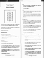
The keypad consists of20 keys most of which have at least two functions . The secondary function is
used when pressed in conjunction with the FUNCTION key at the bottom right of the keypad .
lot 'oo1p111 ·•i on with rotary dial (or up/down keys) used to change the selected increment step
win ·h woll he shown in the top left of the display.
l' o(1 '"K the STE t> key will start the currently selected increment steps to start flashing, by
'""""Kllo · rolary knob on the top of the set or by using the direction arrows on the keyboard you
r un cro ll1h rough the alternate choices, when the chosen increment step is displayed press the red
11:NT (Ent er) key .
Mit (MKMORY REAO)
I r Y''" wosh 10 go straight to any one of the 1000 memory channels simply press the channel
ouuoohcr th ·n MR. /\s you press the channel number the 'digits' will appear in the main part of the
do ~ plny 111ll when you press the M R key this will change to the frequency in the chosen channel,
wrllo lh d tnnnel number now showing on top left of the display
II' you nrc in Manual mode pressing the MR key will take you into Memory mode with the
memory channel showing on the screen. You can scroll through the memory
1 lu""' ·ls by homing the rotary knob on the top of the set or using the up/down keys.
I'"' ·n1ly selected
The primary operation of each key is shown on the button itself while the secondary function of
each key or button is shown in light blue below each key .
II you nr
in Memory mode pressing the MR key takes you back into Manual mode. The
A description of each keys is as follows:-
'"''I" ·n ·y displayed will be the last one you selected in Manual mode.
PRIMARY KEY FUNCTIONS
1'\u moo o cl·rails on Memory operations see Pages 18-22.
Keys numbered 1 to 0 including. (decimal point)
These are used to enter frequencies, memory channels, scan & search banks.
Pressing keys 1 to 0 followed by SEARCH or SCAN will result in the MVT •7100 searching or
scanning those banks selected.
SRCH (SEARCH)
For more details see Pages 29-32.
Press once to start either the search or programmed band search.
If you press the Search key when in manual mode with a frequency shown in the display the
MVT. 71 00 will start to search up or down (you can change the direction if you wish with the
rotary knob or up/down arrows) . No bank numbers will show at the upper right of the screen.
When pressed after a single bank number (i.e 0 to 9) the MVT-7100 will search between the two
frequencies programmed into that particular bank. The bank selected to be searched will show in
the upper right of the display.
1' & ....
i\H wnh tho rotmy dial on top of the set the direction arrows have several uses in different modes.
MANUAL MODE: Pressing either key allows you lo tune up or down from the
di.,played frequency in the increment steps chosen
MEMORY MODE: Pressing either key allows you to mow up or down through the
111e111my channels.
SCAN & SEARCH MODE: Pressing either key when the M'vT-7100 has stopped on a
lrcmsmission will restart the scan or search in the direclion chosen
MODE S ELECTION: Used for the seleclion of AM. Narrow FM. Wide FM, USB or
/,S/J when pressed after FUNC +MODE
INCREMENT STEP SELECTION: Used for the seleclion of any one of the 1urious
111cn:menl sleps when pressed after the STEP billion.
tile direction arrows are also used with the Search Pass Read key (in 1:-ll[(lish it mem1s
can recall which channels you have told the receiver to miss1j ump over when
serrrchinK), these two keys are used in conjunction with the CIAC key when correcting a
keyboard entry.
)'O il
Pressed whilst searching will stop the search.
MVT-7100 Operating Instructions 1.0 10 ]aviation January 1993.
PageS
MVT-7100 Operating Instructions 1.0 <0 Javialion January 1993.
Page9
~c
~o rrection
key, see pages 16 & 17.
T
Enter key. Used to enter Frequencies, Increment steps and Receiving modes.
NC
Pressed first when you wish to use the secondary function of each key. details of which follow.
PGM (6Key)
Used to select memory channels for the Program Scan mode. See pages 26 & 27.
MW (.'\CAN Key)
Memory Write. Use~ when you wish to store a displayed frequency into a specific memory
channel. See pages 18, 19 &32 for further details.
M-+VFO (7 Key)
Transfers the frequency of a memory channel into manual mode when you will then be able to
tune up or down from that particular frequency. See page 20.
CONDARY KEY FUNCTIONS
7/1 ca.~es to access any one of the facilities ddailed below the FUNC key mu.5t be pressed first.
M-SCAN (8 Key)
Mode Scan. Used to start the Mode Scan facility. See page 28.
T (I key)
1\ttenuator. When selected AJT will appear in the display. The attenuator can be selected on any
ndividual memory channel or frequency. In most cases the attenuator should be left 'off', if
1owever strong signals are present it is possible that some interference may occur. To reduce the
;trength of signal and reduce the possibility of interference the attenuator should be selected.
~emember however that pressing FUNC + ATT will only activate the attenuator for that
Jarticular channel/frequency, no other channels or frequencies will be affected. If you wish to
>ctivate the attenuator for a different channel and frequency you must select the memory channel
:he press FUNC + A TT. To turn the attenuator off, select the channel. An· will show in the
jisplay then press FUNC + ATT again. AJT will clear from the screen indicating that the
iltenuator is no longer selected on that channel.. See page 3 5.
P-SCAN (9 Key)
Program Scan. Used to start the Program Scan. See page 26 & 27.
LAY (2 Key)
fhe delay facility will cause the MVT-7100 to pause for approximately 4 seconds after a
:ransmission has ended and before it continues to scan or search. Without delay selected the pause
ime is around 2 seconds. DELAY will show in the display. Pressing FUNC + DELAY again
·eturns the set to nonnal mode. See Page 35
IP (3 Key)
.vhen FUNC +SKIP is pressed in either Scan or Search mode this will cause the MVT-7100 to
:ontinue scanning or searching after approx. 5 seconds from when it stopped on that channel or
i-equency even if the transmission has not finished . SKIP will show in the display. Pressing FUNC
• SKIP again returns the set to staying on a channel for the entire duration of the transmission.
;ee Page 35
I (.'IRCH Key)
MODE (STEP Key)
Used in conjunction with either the rotary knob on the top of the set of the direction keys allows
you to change the mode of reception to either Wide FM, Narrow FM, AM, Lower Side Band
(LSB) or Upper Side Band (USB) on any frequency. See page 13 .
MHz ( 1/tKey)
In conjunction with the C/ AC key can change the MHz digit of the display. See page 17.
SPR (0 Key)
Search Pass Read (what 1). A new facility on the MVT-7100 is that you can specifY certain
frequencies (not channels) to be missed when searching. These can be frequencies with pennanent
interference on or maybe busy channels you just want to jump over. The Search Pass Read Key in
conjunction with the Rotary tuner or direction arrows allow you to see which frequencies you
have instructed the MVT-7100 to miss. For more details see pages 33 & 34 for further details.
BW (MRKey)
Bandwrite. Used for programming the frequency limits within Search banks. See pages 30 & 31.
PASS (OAC Key)
Used for 'locking out' any memory channel or channels you do not wish to monitor in the Scan
Mode. Also used to lock out specific individual frequencies (up to 500) when searching. See
pages 25, 33 & 34.
;elects the monitor of the priority channel. See pages 21 & 22 for more on programming the
'riority channel.
VE (4 h"ey)
)elects and cancels the save function. See page 36.
EP (S Key)
~urns the Keyboard beep on or off_ If REEP is showing at the bott om of the di sp lay then the
ound is on and a Beep sound will be heard each time a key is pressed . If HJ·:u • is not showing in
he display then no sound will be heard. See pages 35 & 36.
....... Time for a break before we get
down to the "Real" business of
button pressing !.....
MVT'-7100 Operating Instructions 1.0 <0 Javiation Janumy 1993.
Page II
MVT-7100 Operating Instructions 1.0 © Javiation Janual)' I YY3.
Page 10
________________. . . . . . . . . . . . . . . . . . . . . . . . . .~. . . . . . . . . . . . . . . . . . . . . . . . . . . . . . . .. -. .Gg. .~~nr11
Til
YUPITERU MVT-7JOO ()PERATION
·o tum the set on slowly rotate the volume knob clockwise. Then rotate th squel ch control fully
nti-clockwise. Adjust the volume control to the desired level (not too loud though) and to silence
]e background noise rotate the squelch control clockwise, at some point the "mush" will di sappear.
II
MANUAL MODE OPERATION
II
Before we look at how to enter and receive frequencies we shall quickly look at how we select the
correct mode of reception and the desired increment steps. These can be changed after we have
entered a frequency.
MODE SELECTION.
To change the reception mode from that shown on the right of the screen press the FUNC + MODE
key. The mode currently selected together with the step size to the left will now flash, by rotating the
tuning dial or pressing the direction keys you can select any one of the alternative modes available.
Once the desired mode is shown press the ENT key. Note that different step sizes may be associated
with each mode
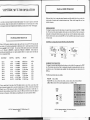
PRE-PROGRAMMED FREQUENCIES
EXAMPLE: To change from Narrow FM (FM) to Wide FM (WFM)
N'hilst all 1000 memory channels are empty when you first tum on your MVT-7100 (or press the
eset button ! ) it has been pre-programmed at the factory with I 0 search bands which are in most
:ases unsuitable for the U.K. listener. To search one of these banks simply press the bank number
e.g. t) followed by SEARCH or bank9 press 9 foUowed by SEARCH. Further details on
;earching and programming your own search parameters follow in a separate section but these are
he pre-programmed limits.
1 ..
j FUNC !~IsTEPI
.l
,-
""
n~rH1
;:) U
WFM
I 1_1 1_1 11 II II 11
I I I.UU!..I.U
MODE
Search Band
Bank
Bank
Bank
Bank
Bank
Bank
Bank
Bank
Bank
Bank
I
2
3
4
5
6
7
8
9
10
StopFr~
Start Freq
76.00
108.00
144.00
146.00
156.00
175 .75
430.00
450 0125
850.025
903 0375
-
107.75MHz
142.00MHz
146.00MHz
154.65MHz
162 05MHz
221.75MHz
440.00MHz
451.50MHz
859.9875MHz
904 .9875MHz
Step Size
50KHz Steps
50KHz Steps
20KHz Steps
lOKHz Steps
12.5KHz Steps
50KHz Steps
20KHz Steps
12.5KHz Steps
6.25KHz Steps
12.5KHZ Steps
Mode
WFM
AM
NFM
NFM
NFM
WFM
NFM
NFM
NFM
NFM
Trying to search Bank 2, the whole of the VHF airband is rather a waste of time, as not only are the
pre-programmed parameters far too wide, the increment steps are in 50KHz, when here in the United
Kingdom we use 25KHz steps so the chance of monitoring active frequencies are rather slim. lt is
advisable when searching to keep the limits to just a few MHz and therefore increase the chance of
locating new frequencies . Further details on programming your own search parameters follow.
MVT-7100 Opcraling Instructions 1.0 ©Javialion Jam~1ry 1993.
Page 12
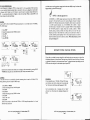
INCREMENT STEP SELECTION.
To change the increment step selection from that shown on the top left of the screen press the STEP
key. The increment steps will now flash, by rotating the tuning dial or pressing the direction keys you
can select any one of the alternative steps available. Once the desired step size is shown press the
ENTkey.
The following increment steps are available:Wide FM 50KHz, 100KHz
Narrow FM 1KHz, 5KHz, 6.25KHz, 9KHz, 10KHz, 12.5KHz, 20KHz, 25KHz, 50KHz& 100KHz
LSB & USBAs Narraw FM but with tile additional choice of 100Hz & 50Hz
jsTEP j
MODE
MVT-7100 Operating Instructions 1.0 <0 Javiation January 1993.
Page 13
NT ERING FREQUENCIES
) enter a frequency in Manual (or VFO) is a simple matter. II can be a good idea to first ensure that
e correct mode and desired increment step are selected but these can be changed as required after
1y frequency entry. Simply key in the frequency required using the numerical keypad followed by
NT. As you press each number it will appear on the screen and flash. When you press ENT it will
ld any trailing zeros and stop flashing.
XAMPLE
tune the MVT-7 100 to 81.3MHz, WFM mode
'FM. 50KHz steps)
J
1
2.
3.
4.
5.
(as~11ming
SlfP
fJ
~
..
•
-1 !..1
i
I
NOTE:- I A linf<hU -fJly thO bU !)
118.025MHz is a 25KHz channel spacing and if you have 50KHz or lOOKHz
selected it will round itself to receive the nearest frequency because the larger
number (50 or 100) does not divide into the smaller. Likewise if you try and enter
a 12.5KHz spaced frequency (e.g. 455.6125MHz) when 25KHz or larger
increment steps are selected it will not be accepted. Within the United Kingdom
the VHF/UHF spectrum is mainly divided illlo 12.5KHz. 25KHz or 50KHz
channel spacing. selecting 12.5KHz will always allow you to enter the exact
frequency as they are all divisible by 12.5KHz. Just to add wood to the fire a
12.5KHz channel spaced frequency will not be accepted exactly if any of the
smaller increme/11 steps down to I KHz are chosen. With a little practice you will
soon get the hang of it !
the set is currently limed to l44.00MHz,
~
SHP _.,.
;; ,-IIIHz-
I 1_11_1 ,-, ,-, ,-, ,-,
I · I 1.!..1!..1!..1.!.1
_-wFM
rcnJ .-1 ,-, ,-, ,-,
I I I.L.IULI.!..I
STEP
•nn•Hz
I U L.f
WFM
/'-1'-1.000.0
[STEP]
MODE
II
ROTARY TUNING I MANUAL TUNING
II
STEP
•I
I
e!
Press STEP
Rotate the tuning knob until 1OOKHz is shown
Press ENT
Press 8 1 . 3
Press ENTER
;
jfldlz
~~ L..l
WFM
I
As a liflle exercise try the previous example but this lime enter 50KHz at step 5 and see what
happens when you press ENT at the end !
I·
I If 1fiiHz
IU!..I
WFM
rt
I ~rtrt II
Cl 1..:t L.1 u. L.l
J
CDCDDCJ:J
M·SCAN ATI
SKI P
If you wish to use either the rotary tuning dial or the direction keys you can tune up or down from
the displayed frequency in Manual mode. Each single turn of the dial or press of the key will increase
or decrease the frequency by the increment steps chosen. To change increment steps simply press the
STEP rotate the tuning knob to the desired steps and press ENT.
If the incorrect mode has been chosen you can change to the correct mode by pressing FUNC
.f'MODE then using the rotary knob followed by ENT when correct mode is shown.
''"'
,- ,-, Ht
.::tU
LSI
·-:.o5 :.a
:XAMPLE
o tune the MVT-7 100 to 1 J8.025MHz, AM mode (assuming the set is tuned to 81.30Mhz. WFM.
OOKHzfol/owing the above example 100KHz steps)
1. Press FUNC + MODE
2. Rotate the tuning knob until AM is displayed
3. Press ENT
4. Press STEP
5. Rotate the tuning knob until 25KHz is shown
6. Press ENT
7. Press 1 1 8 . 0 2 5
8. Press ENT
{(the set was already in AM mode and 25KHz or 12.5KHz steps then procedures 1 to 6 need
not have been carried out
MVT-7100 Operating Instructions 1.0 © Javiation January 1993.
Page 14
EXAMPLE:
If you manually tune to 7.051Mhz. USB and 50Hz steps.
each clockwise turn of the rotary knob or pressing the
"up" direction key will increase the frequency by 50Hz.
~
I
,- n ""Hz
::J !J
MHz
Each anti-clockwise turn or pressing of the "down"
direction key will decrease the displayed frequency by
50Hz.
L-im
LSI
nI.U
,5 I.U
I rt5
f--ITJ
' - - - - - - " - " ' ----'
sa,,""nsn
Hl
I.U
LSI
1:15 I
U •.J
~---_.:c:=--_)
MVT-7100 Operating Instructions 1.0 © Javiation January 1993.
Page 15
CORRECTING A WRONG ENTRY
I
II
CORRECTING OR ADJUSTING THE MHz DIGIT(S) AFTER ENTRY
Should you realise you are entering an incorrect frequency the easiest thing to do to correct your
mistake is, continue, Press ENT and then start again making sure you press the correct keys second
time around, if that is not simple enough you can press the C/AC (Clear/All Clear) key TWICE
while the display is flashing and BEFORE you press ENT. You will then be returned to the
previous frequency displayed and you can start again.
EXAMPLE.
In manual mode the displayed frequency is 1-14. OOMhz but you wish to change this 10 /94. OOMhz
I. Press FUNC + MHZ (the firs/ "4" will flash)
2. Press 1' to select the next digit
3. Using the rotary dial select 9 or just press the 9 key. (The 9 will now flash)
4. Press ENT to complete
However if the above escape routes are not challenging enough the "wizkids" at Yupiteru have
provided another alternative:
By pressing the C/AC (Clear/All Clear) Key while the display is flashing and BEFORE you Press
the ENT key you can, by using the direction keys and rotary knob correct any digit on the screen,
however it has t ob e said this is far more long wmded than JUSt startmg all over agam, but for the
record here's what to do .... ... .
You are now tuned to 194.00Mhz
!'i
SI£JO
j r1111Ht
!.. U
FM
I'-/ '-1.0[J0. 0
..
m•
:r U1
n•Hz
L
I C,1
FM
,_{Ef,-1 ,-, ,-,
lA I.
'I'
U!..I.U
.
J
I
STEP
1fiiHt
\ !U/
1
EXAMPLE. .
You imended lo emer 128.00 but accidently keyed in 138.
m•
,- riiiHl
~
r
/, 1 -. :
T
"AM
1-,
-~
1.:t.b
;m
DELAY
STEP
STEP
AM
1:1;:1
1!...!..1
f/
--------~K~
"--~
.
'
,-,
:Jif-'·uuu.u
anr
""
JrJIIHl
U
C
•
FM
I9 '-1.000.0
""
EXAMPLE.
In manual mode the displayed frequency is 468.955Mhz but you wish to change this to 145.955Mhz
I ..,.
I
#1'""0
5[1'"'"
•
""
:r1fiiiHt
4 t.J
FM
' I ,-, ( I rl ,-, rr
0MHz
I. ·Press C/AC while 138 is still flashing
(The 8 will now flash a little quicker than the rest of the display)
2. Press the 1' to select the 3 digit. This will nDM•.flash a little quicker.
3. Using either the rotary dial select the correct digit, in this case 2 or just press the 2 key
4. Press ENT
5. Complete the entry of 128.00 by pressing the"." then ENT
.:r1.1
FM
:')Ill IJ rl rl rl rl
-l, ,:::J.UUU.U
i
l
I
C rJitHz
AM
I -1,-1 it il it ,-,
tCCt.C/!..1!..1.!..1
-1 L.l
~---------=~~
EXAMPLE
You key in 3-15.875 but ill/ended to e/1/er 354.875.
I . Press C/AC while 345 .875 is still flashing
(The 5 willnow.flash a little quicker !han/he res/ oflhe display)
2. Press the 1' 3 times to select the 5 digit. (This will now flash a lilfle quicke1).
3. Using either the rotary dial select the correct digit, in this case 4 or just press the 4 key
4. Press the 1' to select the next digit left (!his "4" will now flash a /ilfle quicker)
5. Using either the rotary dial select the correct digit, in this case 5 or just press the 5 key
6. Press ENT
7. Complete the entry by pressing the ENT key.
MVf-7100 Operating Instructions 1.0 © Javiation January 1993.
Page 16
I . Press FUNC + MHZ (Ihe first "8 " will flash)
3. Using the rotary dial select 5 or just press the S key.
2. Press 1' to select the next digit
3. Using the rotary dial select 4 or just press the 4 key.
2. Press 1' to select the next digit
3. Using the rotary dial select I or just press the I key.
4. Press ENT to complete
You are now tuned to 145.955Mhz
..... I'll get him... He said it was
easy to use ........ .
MVf-7100 Operating Instructions 1.0 10 Javiation January 1993.
Page 17
,.,
11111111
EXAMPLE
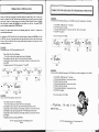
To store 441.8125MHz. NFM mode in channel 127 (assuming the set is currelllly displaying
123.50, AM and 25KHz incremelll steps following the previous example)
STORING FREQUENCIES IN MEMORY CHANNELS FROM
MANUAL MODE
e MVT-7100 has 1000 memory channels, (plus one other when you count the priority channel)
~ani sed in 10 banks of I 00 channels into which you may program any frequency and mode,
!nuator settings can also be stored . Memory channels are shown as a three digit number on the
of the display. It can be a good idea to group types of frequencies together, for example, store
your VHF airband frequencies in one bank, all the UHF airband frequencies in another and so
th .
store a frequency in a memory channel it is first necessary to follow the procedures for manual
,ing described earlier. It is then a simple case of informing the MVT -7 I 00 which memory channel
J wish to store the frequency in.
I. Press FUNC +MODE
2. Rotate the tuning knob until FM is displayed
3. Press ENT
4. Press STEP
5. Rotate the tuning knob until 12.5KHz is shown
6. Press ENT
7. Press 4 4 I . 8 I 2 5
5. Press I 2 7
6. Press FUNC
7. Press MW
MEMORY STORAGE- CONSECUTIVE CHANNELS
A bit difficult to describe this one without being too long winded.
AMPLE
store J23.50MH:., AM mode, in channell3. (assuming the set is in AM, if not refer to the earlier
tion on selecting the correct mode and increment step size)
L Press 1 2 3 . 5
So if you want to store a set of frequencies in consecutive channels the following routine can be
used:-
2 ~ Press ENT
3. Press 1 3
4. Press FUNC + MW
The MVT -7100 will confirm the entry by a double beep (if the sound is on !) and temporally
show the memory channel on the left of the screen then return to normal Manual mode.
I
STEP
C MtHz
.J Ll
By pressing FUNC + MW without specifying a channel whilst a frequency is displayed in manual
mode will store this frequency shown into the LAST MEMORY CHANNEL DISPLAYED in
memory mode - so if memory channel 066 was displayed in either memory mode or scan mode and
you have manually entered 129.875MHz, pressing FUNC + MW will store 129.875MHz in channel
066 overwriting what was there before. Subsequent presses of FUNC + MW will result in
129.875MHz also in channels 67, 68, 69, 70 and so forth.
m•
( _,c Un•Hz
.• I
AM
123.500.[/
~--------~~
GJITJCTID
ATI DELAY SKIP
o::::::J --+ I ENT I
GJITJ
ATI
SKIP
BEEP
MVf-7100 Operating Instructions 1.0 © Javiation January 1993.
Page 18
t:r~;:
AM
I. Enter first frequency to be stored
2. Enter the channel number you wish to start at
3. Press FUNC + MW
4. Enter second frequency to be stored
5. Press FUNC + MW
6. Enter third frequency to be stored
7. Press FUNC + MW
rtrt rt
IL .3.-ILILI.LI
~--------~
MI~'---
After each press of FUNC + MW the channel number will appear on the screen for a short
moment.
.. ... and so forth BUT REMEMBER that storing a frequency in a memory channel will overwrite
any information that is already stored in that memory channel and if you do not enter a specific
channel at operation 2 above then the MVT-7100 will start to store frequencies from the last
memory channel that was displayed on the screen.
Mvr-7100 Operating Instructions 1.0 © Javiation January 1993.
Page 19
RECALLING A MEMORY CHANNEL
CLEARING A MEMORY CHANNEL
II
.ny one of the 1000 memory channels can be recalled. If you wish to recall channel 13 simply press
3 +MR. The MVT-7100 will now be in MEMORY MODE and the display will show the channel
umber and frequency stored in it.
If you wish to clear the contents of a memory channel press FUNC + MW when the channel you
wish to clear is displayed . Once cleared the display will show OOO.OOO.OMHz.
EXAMPLE
To clear memory channel 013.
G
ln Memory Mode you can use
'"'1
1nn•H
IUU
"": :~l! •
, .J
J
INH
_
n
U
'-='
I ~CH
123.500.0
[§]
CIJCIJ
ATI
SKIP
I. Press 1 3 + MR (If this channel is no/ already selected)
3. Press FUNC + MW
either the rotary tuning dial or the
direction arrow keys to select any
channel. Each single turn of the dial or
press of the key will move to the next or
previous channel.
AM
II
13~'~
[/
••
1~7:500.0
BW
[/ :3,.
•
••
nnnnnnn
UUU.t..IUU.U
[ I ] o:::J _, [§]
ATI
SKIP
BW
PRIORITY MEMORY CHANNEL- FREQUENCY STORING
·o change from MANUAL (VFO) Mode to MEMORY Mode or Vice-versa simply press the MR
ey.
One additional memory channel, channel number 1000 is available as a Priority channel. Any
frequency and mode within the receivers coverage can be stored in this channel and monitored every
5 seconds irrespective of whether the unit has stopped on any other frequency or is in Manual, Scan
or Search mode.
TRANSFERRING A FREQUENCY FROM A MEMORY CHANNEL
TO MANUAL MODE
EXAMPLE
To store 158.35MHz as the Priority frequency
f you wish to transfer the contents of a memory channel into the MANUAL (VFO) mode simply
'ress FUNC + M-+VFO. You may then either tune up/down or search from the displayed
requency in manual mode.
:XAMPLE
"ransfer the frequency contained in Channel 013 to mmmal mode
I. Press 013 + MR (To recall chanel 013
2. Press FUNC + M-+ VFO
D f3cH
if not already on that channel)
I
AM
123.500.0
~--------""--~
•
,-
...
AM
/:!:Jrnnn
lL_'c_~_._~_~.._'u~.t..-'~
1
[ I ] o:::J --~
ATI
SKIP
)
STEP
I ,-111Hz
f !..I
FM
158350.0
i•l
I
'
nuz
~u
1
I. Press 1 5 8 . 3 5 + ENT
3. Press 1 0 0 0
4. Press FUNC + MW (P ch will temporally show & the display will
then return to manual mode)
BW
The Display will still show the same frequency but the memory channei number, in this case
013 will be replaced by the currently selected increment step.
MVf-71 00 Operating Instructions 1.0., ]aviation January 1993.
Page 20
CIJCDliJD
ATI BEEP PIA-SCAN
o:::J CD_, IEI<T I
SKIP
(
·I
l
1n•Hr
•u,\,l!;nnm •
1!../U.!..I
,
I
""
I
I
''-- - --
----'
[ I ] [DITJITJ
ATI
SPA
SPA
SPA
BEEP
SU!"
I rfAHl
1!..1
AI
158.350.0
~------
MVf-7100 Operating Instructions 1.0 0 ]aviation January 1993.
Page 21
TO MONITOR PRIORITY MEMORY CHANNEL
To set the receiver to monitor the Priority channel press FUNC + PRI.
PRJ will appear in the bottom centre of the display.
MEMORY SCANNING
II
The memory channels in the MVT-7100 are organised in 10 banks of 100 channels. Once you have
programmed frequencies into the MVT-7100 memory it is possible to scan either all the channels or
a selection ofbanks.
Bank 1 = Channels 000-099
Bank 2 =Channels 100-199
Bank 3 = Channels 200-299
Bank 4 = Channels 300-399
Bank 5 = Channels 400-499
Bank 6 =Channels 500-599
Bank 7 = Channels 600-699
Bank 8 =Channels 700-799
Bank 9 = Channels 800-899
Bank 0 = Channels 900-999
The Priority channel will be checked for activity every 5 seconds, this will cause a slight "break"
dunng the reception of any other transmissions. If the Priority channel is active then this frequency
Will be received, once the transmission on the Priority channel has ended the set will return to the
prev1ous mode of operation.
STEP
I,-, ;-rlrHz
1!_1 U
WFM
::rCH
8 1.300.0 •
(imD--------·
Pftl
SEEP
FM
158.350.0
'
II
If you wish to scan the entire contents of the memory simply press the SCAN key. You may have to
adjust the squelch control to allow the set to scan through the channels.
The display will show each channel number and frequency as it scans through the banks. If you have
frequencies in all I 0 banks the display will also show all the bank numbers across the top.
TO CHECK THE CONTENTS OF PRIORITY CHANNEL
When a transmission is detected on one of the frequencies the receiver will stop on that particular
channel until either the transmission ends or you either rotate the rotary dial on the top of the set or
press the direction arrow keys to start scanning again in either up or down through the channels.
If you have activated the Priority channel (see previous section) there will be a short break during the
reception of signals when the receiver "jumps" to the Priority channel to see if that channel is active.
If you wish to see which frequency is currently stored in the Priority channel recall channel 1000 as
you would any other memory channel press 1000 + MR.
EXAMPLE
To start scanning the all the memory channels that have been
programmed.
1. Press SCAN
STEP
I it 11Hz
'u '.\,;;,-,nil • 1
IUU.U
.
c:Dmmm
ATI
SPA
SPA
SPA
1
JJCH
FM
158.350.0
,-, ,.., c
-
I
~· !t , l iSD
I!
L.l t•.=tL.IU.L.I
I
ll!ltJ•a:·---::,-•
.
""/ I \
SCAli
!..1 !..1-ICH
Cl
~
BW
WFM
I -,,-,II
,-,
/SCAN/
MW
When the Priority channel is recalled ..
p ch" will be dispalyed rather than channel 1000.
When the set stops on a transmission the bank number
will flash indicating which bank the channel received is
ln .
MVT-7100 Operating lnstmctions 1.0 0 }aviation January 1993.
MVT-7100 Operating Instmctions 1.0 eJaviation January 1993.
Page 22
Page 23
TO STOP SCANNING
II
Pressing the SCAN key whilst scanning will stop the set on whichever channel it happens to be on
and return you to Memory Mode. You can select other memory channels from this point by either
using the rotary dial, direction arrows or by entering the desired channel followed by MR.
MEMORY CHANNEL PASS (LOCKOUT)
II
In the previous example (Selective Memory Bank Scanning) we have seen how we can program the
MVT-7100 to scan just one or up to 4 individual banks. You may also wish to lockout or omit a
single channel or channels from a particular bank whilst scanning.
EXAMPLE
To pass (lockout) channe I 013 when scanning.
You can also press the MR when scanning and you will be returned to memory mode, just the same
as pressing the SCAN key as above. Key in a memory channel followed by MR when scanning and
you will go direct to the chosen channel.
1. Press I 3 + Press MR (If channel not already displayed)
3. Press FUNC
4. Press PASS
If you wish to return to Manual mode when Scanning press the MR key twice.
a :3..
SELECTIVE MEMORY BANK SCANNING
rt
AM
IC'3.5DD.D •
II
&./
I~~/-
l,:fcH-
u
1215DD.D
...
[IJ[TI-+~
ATI
By pressing the SCAN key you scan all the memory channels that you have programmed frequencies
in to. However more often than not you may not wish to scan the enitire contents. If for example you
have grouped frequencies together and all your local amateur frequencies are in Bank I then you
may wish to scan just that one bank or you may wish to scan the banks that contain your VHF &
UHF airband frequencies. By simply pressing the bank number or numbers prior to pressing the
SCAN key you can tell the MVT-7100 which banks to scan.
SKIP
BW
The small "ch" after the memory channel will now flash indicating
that during scanning the unit will "pass" this channel. The channel
can still be recalled by manually in memory mode.
You can also pass a channel in memory scan by pressing FUNC +PASS during a transmission, next
time round this channel will not be monitored.
EXAMPLE
To scan banks I, 2 and 0.
I. Press 1 2 0
2. Press SCAN
.
lllm•·------· mm.:J--------·
- ,,_
$ttl'
,- ntHr
~u
\\t~nli •
1!...!..1
aaSa/'~~
t :rnn ,,
'-:r-:r
SCM
8
f
ATT
DELAY
.:JCH
~p'
. . .,
stAll
fM
156.800.0
I• .J!..J!..J.!..J
lUI'
mmm
C
'"'
CANCELLING CHANNEL PASS
SPR
I
The MVT-7100 will now only scan banks I, 2 & 0, you will notice that the display will only show
these 3 banks at the top of the screen. When the set stops on a transmission the bank number will
flash indicating which bank the channel received is in.
T o cancel Memory channel pass simply recall the particular channel and press FUNC + PASS again.
The small "ch" after the channel number will stop flashing.
If you had selected to scan just bank 7 by pressing 7 + SCAN then the small figure 7 on the display
would show and you would only be scanning channels 600- 699.
MVf-7100 Operating Instructions 1.0 «.!! Javiation January 1993.
MVf-7100 Operating Instructions 1.0 O Javiation January 1993.
Page 24
Page 25
Jl
II
PROGRAM SCAN
A useful facility on the MVT-7IOO has been provided so that you can program the set to scan any 10
individual channels from each bank. Up to 100 different channels can be scanned (no more than 10
from any one bank though) without having to lockout or Pass numerous other channels that you may
not wish to scan.
So for example, if you put channels 5, I22, 145, 166, 255, 367, 389, 399, 499, 501, 523, 822, 823,
868, 976, & 999 into the Program Scan memory each time you pressed FUNC + P-SCAN all these
memory channels would be scanned. You can also just scan a single bank or any number of banks
just like "normal" scanning.
EXAMPLE
To emer channel 5 illlo !he Program Scan Memory
E XAMPLE
7(J scan on(y the Program Scan channels in Banks 9 & 0
II
I. Press 9 0
2. Press FUNC + P-SCAN
n
"''
10 [f'"' "
[
AM
s.a
""
{,
8 9 UCH
-·
r0
"•-SUI ...... . ,...
.;;J
•
• I -,;:nnnnn
n
1
I UCH
J!\
Kll-stAM .....~~ ......
AM
• ' :~ 1;: onnn
.lliSJ•·----=-·. I:IID------.':-
'l
.:11...1 I.UUU.U
J
-'
l_l.t:II...IU./...1 •
mm
P-SCAN
SPA
PGM-SCAN will be displayed together with the banks being scanned, in th_is case just 9 & 0. When a
transmission is received the bank number in which the channel is located wtll flash.
If the bank or banks selected for Program Scan have no Program Scan memory channels entered
"Error" will be displayed.
I. Press 5 + MR (To recall channel 5)
3. Press FUNC + PGM
.
,,-
~CH
WFM
B 1.300.0
I
il IIi
U !..J :JCH
PGM
WFM
B 1.300.0
REMOVING CHANNELS FROM PROGRAM SCAN
- - - --='--- J
~-CD
PGM
The letters PGM will be displayed and flash when any channel that has
been entered into the Program Scan is re-called.
EXAMPLE
To cancel channel 5 from the Program Scan Memory
EXAMPLE
To scan all !he channels in Program Scan
I. Press 5 + MR (To recall channel 5- PGM will be .flashing)
3. Press FUNC + PGM (PGM will no longer be displayed)
I. Press FUNC + P-+SCAN
FI.HIC
UtP
rr rr•Hr
.uo
:J::JL .-:~nn ,,
t.. ~o.ouu.u
To cancel a channel from the Program Scan memory you re-call the memory channel and repeat the
same procedure as above except that this time the letters PGM will disappear and the channel w1ll
then no longer be in the Program Scan memory.
-3/:1-.tSI1111
t
12 3CH '";';S<II
IUU
..
156.800.0
fllll--------·
m
P-$CAN
a . . ,,.. . . .
I
[1 SCH :-;;:.::I [I 0 Set! WfM
•
,-, 1 -,,-,nn
l - 1nn ;,
B 1.31...11...1.1...1
1
1
L_------~·~
·"--~'
l
Cl 1•.:1/...IU.U
F'
!FlJNC!- o::::J
PGM
PGM-SCAN will be displayed together with the banks being scanned. When a transmission is
received the bank number in which the channel is located will flash.
MYr-71 00 Operating Instructions 1.0 10 Javiation January 1993.
Page 26
Mvr-7100 Operating Instructions I. 0 0 Javiation January 1993 .
Page 27
II
MODESCAN
Another little useful scanning mode provided on the MVT-7100 is Mode Scan. lffor example you
wanted to Scan all the channels that had been programmed in FM you would select "FM" mode in
Manual mode and press FUNC + M-SCAN. You would then scan any memory channels that
contained frequencies in FM mode.
This can be particularly useful, if for example you wanted to scan all your airband frequenci es (which
would he in AM, if they are not they should be I) but they were spread between several different
banks. Rather than have to mess around with passing channels or selecting only certain banks to scan
it is a simple case of selecting AM on any frequency in manual mode then FUNC + M-SCAN. Hey
Presto you now are now scanning only frequencies in AM.
SEARCHING
II
To start storing frequencies into memory channels assumes that we already know what frequencies
we want to listen to either through previous experience or via one of the many publications now
available. If you wish to try and locate new active frequencies within certain pans of the radio
spectrum the MVT-7100 has a Search facility which will allow us t~ rapidly "search", in any ~ode or
increment step up or down from a displayed frequency or alternauvly between two frequenc1es To
start the MVT-7100 searching up from a displayed frequency just press the SEARCH key, the
MVT-7100 will ultimately work its way to 1650MHz. By rotating the tuning knob or pressing the~
direction arrow you can reverse the search direction to go 'backwards' all the way to 530KHz ..
EXAMPLE
7he displayed frequency, in manual mode is 903. 13 75, FM, 12.5KHz steps. Press SEARCH to start
searching upwards from the displayed frequency.
As with "normal" Scan and Program Scan channel pass can be used and you can specify a single
bank or upto 4 different banks in Mode Scan. So if you only wanted to scan those frequ encies in FM
in Banks 4 & 7 you would select FM on any frequency in manual mode, then press 4, 7, FUNC, MSCAN.
m•
/2.51rHz
FM
9D3. 13'1.5
sm
I ':'I CIt Hz
IC.-1
• Cl!l31--------·
903.200.0
""
EXAMPLE
To scan only those frequencies stored in WFM mode
1f you wish to change the reception mode or increment steps you may do so while the set is
sc~rching following the instructions earlier on page 13 .
1. You must be in manual mode, any frequency will do in WFM
2. Press FUNC + M-SCAN
STE,
· nn•Hl
UU
WFM
BD.ODD.D
,,,,:
•
-.....~J,\~,~~' '''
U U JCH -WFM-
B I..:JUU.!..J
1 :tnn,,
•
BID•••••••••
'"'
- l l H S 6 71 9 1
f50cH ~~:M~
1;:11,
SEARCH
FM
I
II
PRE-PROGRAMMED SEARCH BANKS
iit:h ,,
IJ I. IJ!..J.!..J
DID•••••••••
l U I'
The MVT-7100 has been pre-programmed at the factory with the following 10 search banks which
11 1c in most cases unsuitable for the U.K. listener.
Search Band
When in Mode Scan SCAN will be displayed togther with the selected mode which will be flashing.
When a transmission is received the bank number in which the channel is located will flash . PGM will
flash with any channel that has been included in the Program Scan aswell.
To return to normal Scan mode simply press the SCAN key.
To return to memory mode press either FUNC + M-SCAN again or just the MR key. Key in a
memory channel followed by MR when scanning and you will go direct to the chosen channel.
If you wish to return to Manual mode when in Mode Scan press the MR key twice.
Bank
Bank
Bank
Bank
Bank
Bank
Bank
Bank
Bank
Bank
l
2
3
4
5
6
7
8
9
10
Start Freq
76.00
108.00
144.00
146.00
156.00
175.75
430.00
450.0125
850.025
903 .0375
Stop Freq
-
107.75MHz
14200MHz
146.00MHz
154.65MHz
162 05MHz
221.75MHz
440.00MHz
451.50MHz
859.9875MHz
904.9875MHz
StqJ Size
50KHz Steps
50KHz Steps
20KHz Steps
10KHz Steps
12.5KHz Steps
50KHz Steps
20KHz Steps
12.5KHz Steps
6.25KHz Steps
12.5KHZ Steps
M(Jde
WFM
AM
NFM
NFM
NFM
WFM
NFM
NFM
NFM
NFM
'Jo start searching a particular bank simply press the bank number followed by SEARCH .
Mvr·7100
Operating Instructions 1.0 0 Javiation January 1993 .
Page 28
MVf-7100 Operating Instructions 1.0 0 Javiation Janual)' 1993.
Page 29
EXAMPLE
To search Bank 0
I . Press 0 (0 will flash)
2. Press SEARCH
The set will now start searching from 903.0375MHz to 904.9875MHz stopping on any active
frequencies. The 0 at the top right of the display indicated Bank 0 is being searched.
,'/-(.. -
-;u .;
/ I \
.
12.5
snr
FM
,
II: CI3C it it
t.:ID •
.;:JI../.1..1
..
'I l I I
STEP-I 2 3'
'2.5*Hr;t(.,i
,, tC C1
~.
1 I I 0 -
~ ,,,, ,
1
i •
~'---------'~_J
snr 12l4~1 l ltl ~
(
,
903. 13'15
(;I!lD----
1
:u: . Hr/ / 11
.... 1 1!;; ..;1
, 11 , ' ' \
'\i:_// 1..
....
D
I
....
tf
I
,
-,
c
r,
,
\\\I I
I // /
1Hf'- 12l4~ 17 11 o...:..
I:JC*HY / i f l ! \ \ \ ' 1
~~· c;: __ ,
FM
I
~ ~~..t:r::r
::r ,,
II: 1:._1
I'
:
l
l(f P
Q:Jo:::Jo:::JD
Q]ITJ[IJCJ
[IJ -- li@
r::::IJ--1 ENT I
, DELAY
sC.al
SAVE
DELAY DELAY
SKIP
sur
1cH1
'~;.:',...t:IL!.",-,,-,
t.=tti •.:LIU.I..I
I''--~-
0PGM
PAl
EXAMPLE
To search Bank 9, between 850.025MHz and 859.9875MHz, FM, 6.25KHz steps.
I. Press 9
2. Press SEARCH
PROGRAMMING NEW SEARCH BAND LIMITS
I I 1'/
STI '-11 1~ ~6 1 19-;:,
1 1':1511Hr"""F"' ' ' '''' I
FJI!
:li: ,-,It /I • i'\.d':r
'
:r"
.
II..!.. .I:
1-ID.-IJU.!../
- • FM
lfHt
t
II
SAVE DELAY DELAY
§]
I
'i
llfP
I 2.5Uil
you have now re-programmed bank 6. When you now press 6 + SEARCH your set will search
bet ween 422.20MHz & 422.30MHz in Narrow FM and 12.5KHz increment steps.
II
EX AMPLE
'f i> program search Bank 2 to start at 324.20MH:. &finish at 330.00MH::
Whilst the pre-programmed bands may be a great interest to Fred Bloggs living in downtown Tokyo
they are of little use to you Fred Bloggs of downtown U.K.
To make the best use of the search banks we need to re-program them with frequencies of your own
interests. Try and keep the limits to just a few MHz as to increase the chance of receiving previously
unheard transmissions. Just do a few MHz at a time as it will prove far more productive than trying
to do the whole lot in one !
To program search limits is a relatively simple operation(!!), all we need to do is enter the start and
end frequencies into one of the I 0 search bands.
If you want to set the Mode and Increment steps that you wish to Search in you can do so in Manual
mode before you re-program any banks. You can however change the Mode and Increment steps of
any Search Bank while searching.
EXAMPLE
To program search Bank 6 to start at422.20MHz &finish at 422.30MHz
I. Ensure you are in manual mode and not searching or scanning (In the example he/ow the
set is /lined to 158. 35MHz, Narrow FM in 12.5KHz steps)
2. Press FUNC + BW (!he display will now flash)
3. Press 4 2 2 • 2 (The bottom limit/the jreq11ency we wish to start at)
4. Press ENT
5. Press 4 2 2. 3 (The lop limit/the frequency we wish to finish at)
6. Press ENT
7. Press 6 (this is the bank we will store these limits in)
8. Press ENT (lf the "beep" is still on a do11ble beep will so1md to indicale the above has been
accepted the dipslay will ret11m to the previo11sjreq11ency in manual mode)
MVT-7100 Operating Instructions 1.0 10 Javiation January 1993.
Page 30
1. Ensure you are in manual mode and not searching or scanning
2. Press FUNC + BW (The display will now flash)
3. Press 3 2 4 . 2 (!he bottom limit/the frequency we wish to start at)
4. Press ENT
5. Press 3 3 0 (The top limit/the frequency we wish to finish at)
6. Press ENT
7. Press 2 (this is the bank we will store these limits in)
8. Press ENT
DON'T FORGET if you want to change the mode or increment steps you
can do so when the set is searching by simply by pressing FUNC + MODE
then rotating the rotary knob and pressing ENT or to change the steps just
press the STEP and rotate the tuning knob then press ENT
The same procedure should be used for re-programming any of the other
bands with frequency limits of you choice but remember keeping the limits to
just a few MHz (no more than say IOMHz) will greatly increase the chances
of locating previously unheard active frequencies .
MVT-7100 Operating lnstructions 1.0 0 Javiation January 1993.
Page 31
SEARCH PASS MEMORY
STORING FREQUENCIES IN MEMORY FROM SEARCH
\I
You can store frequencies found during Search direct into any one of the 1000 memory channels by
pressing FUNC + MW whilst the set remains on a transmission. The frequency on the dipslay will be
transferred into memory.
When searching it is possible to program the MVT-7100 to pass those frequencies which al~ays
cause the receiver to stop. These frequencies may be local mterference, data s1gnals or maybe just
If no channel is specified the frequency will be transferred into the last memory channel re-called. If
you wish to store the frequency in a specific memory channel key in the memory channel then
FUNC+ MW.
Up to 500 different frequencies can be entered into the Sear~h Pass Memory, any frequency that is
stored in this memory will not be monitored when the umt 1s searchmg. If you try and ~nter more
than 500 frequencies in the Search Pass Memory "FULL" will be di_splayed an~ you w11I have to
remove some frequencies before others can be added . Any frequencies stored m the Search Pass
Memory can still be recalled in Manual, Memory or Scan mode.
EXAMPLE
Tl1e set searching from 230.00MHz upwards and stops on 236.80MHz. you wish to store this in a
memory channel.
freq uencies you do not wish to monitor.
I f you know of any frequencies you wish to enter into the Search Pass
M~;~ry, e;t~r ~h:~ in
Manual mode then press FUNC +PASS. The display will temporally show a
on t e e
e ore
returning to manual mode.
I . Press FUNC + MW while the set is 011 that frequency
STEP
I if illcHl
I~~
do not wish to monitor in future press
If w hen Searching the MVT-7100 stops on a signal you
.
.
h
"/'" h
FUNC +PASS while on that particular frequency, the d1splay will temporally s ow
t en resume
STE P
Sf ARCM
!.1
AM
;-1
U
11_1
I
ICH
SEAIIQI
AM
I,-, illcHl
lULl
S~ AMCM
AM
c'3G.EIOO.O • i c'3G.EIOO.O • C'3G.EIOO.O
Q!ID--------· tmm--------· l(g--------·
BEE P
BEEP'
N tl~
lsACHI
searching.
f XA MPLE
"JIJ .vtore 128.80 into the Search Pass Memory.
PAl
Memory channel 14 was the last channel re-called so 236.80MHz will now be stored in that channel
replacing the existing frequency. If you wish to store any further frequencies int o subsiquent
channels each press of FUNC + MW will store the frequencies in channels IS , 16, 17 and so fo rth .
EXAMPLE
The set searching from 230.00MHz upwards and stops on 236.80MHz. you wish to store this in
memory channel /34.
I. Press l 3 4
2. Press FUNC + MW while the set is 011 that frequency
I . Press 128.80 + ENT
2. Press FUNC +PASS
A "P" appears on the left of the display then the unit returns to manual mode
~R~'ont!t n
(]lij------.:.-•
tC Ct.D!..I!..I.!..t
I•
i
l
STEP
,- rfltH t
fp,-,,-, cmt!t n
1 ..
i
t ~------.:.-• j
tC Ct.!:ll../!..1.!..1
,
~
!..1
AM
Ic'B.B00.0
rnD•·------·
IHP
GJCIJCDD
ATI DELAY M-SCAN
C::::0 --+ 1ENT I
M·SCAN
,. ' MPLE
/o store 353.20 into the Search PassMemmy during Search
2. Press FUNC +PASS (when SlOpped on the desired.frequency~
A"/' " appears on the left of the display then the units continues searching
I
!I
t
MVf-7100 Operating Instructions 1.0 <1:1 )aviation January 19'.13.
Page 32
sn•
,-,c:••'
c -,
I
FM
"- I\
-mn if
.:t_t.:t.C!..Il../.!..1
""JC -,
E!Bl-----
IUP
I
1
(
I~ p
.. r ""JC
I
llliJ-----
t
m•
1 I IC.=I
I -1I
-• ,_- -, -, Jl II Jl
lrHl
SUIICH
:t =''''' if
_;,_,_I.L!..I!..I.l.J
FM
I
I .. I
Sf.f.RtH
FM
.:Lt .=t•.=t u 1..1. 1..1
IHP
MVf-7100 ()per31ing Instructions 1.0 (l Javiation January 1993.
Page 33
CHECKING CONTENTS OF THE SEARCH PASS MEMORY
ATTENUATOR
II
If
. h
you WIS to check the contents of the Search Pass Memory you must be in Manual mode then
press FUNC + SPR.
The "P" h
·
·
p
M s own to the left of the d1splay w1ll be flashing when recalling frequencies stored in Search
~ss emory. The first frequency to be displayed will be the one nearest the frequency shown in
Manual Mode JUSt before you pressed FUNC + SPR. If no frequencies are in the Search Pass
emory then "Error" will be displayed.
~y us~ng the Rotary dial or direction arrows you can scroll
through those frequencies stored in the
e arc Pass Memory. If only one frequency is stored in the Search Pass Memory then the display
WI 11not alter.
To return to Manual mode either press FUNC + SPR again or the C/AC key once.
II
When strong signals are present on certain frequencies some interference
may occur. To reduce the signal strength of strong signals the
Attenuator should be switched on. To tum the attenuator on press
FU NC + ATI. When the attenuator is on AIT will be shown in the
display. In memory mode the Attenuator must be set for individual
channels. ln Search or Manual mode the Attenuator will be on for all
frequencies. To tum the attenuator off press FUNC + ATI again.
The Attenuation is approximately -lSdB (at 108MHz)
~-~~
iiiiiiiiiiiiiii~~~
iiiiiiiiiiiiiiiiiiiiiiiiiiiiiiiiiiiiiiiDELA
y
REMOVING FREQUENCIES FROM SEARCH PASS MEMORY
·h
you WIS to remove any frequencies from the Search Pass Memory and therefore monitor them
when searching you must recall the frequency as described above, and when the frequency is
ISp ayed press FUNC + PASS. The display will then show the next frequency in the Search Pass
M emory.
If
~gal~
EXAMPLE
To remove 13.270MHzfrom the Search Pass memory
I . You must be in Manual Mode
2. Press FUNC + SPR
3. Using the rotary dial or direction arrows to select 13 .270MHz
4. Press FUNC +PASS
Aller a transmission has finished the MVT-7100 will continue to Scan or Search after approximately
2 seconds. lf you wish the resumption to be a little longer to perhaps allow for a delayed reply then
hy pressing FUNC +DELAY there will be a 4 second delay.
When the Delay facility is on DELAY will be displayed. To cancel the Delay facility press FUNC +
UELA Y again.
SKIP
II
1>1uing Scan and Search the MVT-7100 will remain on a frequency for the duration of the
lr n11smission, with the Skip facility on scanning or searching will contiue after 5 seconds of stopping
" " n ll cquency. To turn Skip on press FUNC +SKIP. With skip on SKiP will be displayed. To turn
1111• "k'fJ facility off press FUNC+SKIP again.
:f you remove the last freq
fr
h S
h
·
vf
uency om t e earc Pass Memory you w1ll automatically return to
1
anua Mode. To return to Manual mode either press FUNC + SPR again or the C/AC key once.
BEEP
Wrth the beep sound on BEEP will show in the display. To tum the beep sound off press FUNC +
nt:t:l). With the beep sound off press FUNC + BEEP to turn it back on again
MVr-7100 Operating Instructions 1.0 © Javiation January 1993 .
Page 34
MVf•7100 Opcr.uing Instructions 1.0 (l Javiation January 1993.
Page 35
II
There are 3 types of"Beep" !
0 A single Beep is heard each time a key is pressed.
& A double Beep is heard when you store and erase information.
0 Three Beeps (the latter two slightly higher in tone) indivcate and Error.
II
BATTERY SAVE
II
By turning the Battery Save facility on you can put the MVT -7100 into several states of standby
mode, this will reduce consumption.
The Save facility will only work when in Manual or Memory Channel Recall mode. There are 3
Save Modes:SAVE MODE
PERIOD OF NON OPERATION
1
0.3 seconds
2
0.9 seconds
1.5 seconds
3
When the Save facility is turned on and there is no activity on the selected frequency for 5 seconds
after the end of a transmission the MVT-7100 will enter the selected Save mode and monitor the
displayed frequency for 0.3 of a second. If for example Save Mode 1 was selected, the MVT -7100
would monitor the displayed frequency every O.J seconds for 0.3 of a second, if Save Mode 3 was
selected the frequency would be monitored every 1.5 seconds for 0.3 of a second .
When a signal is detected the MVT-7100 will "tum itself on" for the duration of the transmission
then return to Save mode after 5 seconds of non activity.
Does all that make sense ?
EXAMPLE
To Set Battery Save Mode 3
I. Select chosen frequency either in Manual or Memory recall Mode
2. Press 3
3. Press FUNC +SAVE
/2 3CH
FM
15G.BIJO.IJ
..
""
: 2.5'"'
m
/2 3cH
FM
'C.t::.annn
I..J!.J. UU.U
""
SKP
The unit will stay in Save mode whilst remaining in Manual or Memory recall mode even if you tum
the set off and back on again. To cancel Battery Save press FUNC + SAVE.
That's it - Finished .. .
... What ! A false start .... l've
got to start again ... Aghhh ..
If you start the set scanning or searching Battery Save will be cancelled automatically.
MVf-7100 Operating Instructions 1.0 © Javiation January 1993.
Page 36
MVf-7100 Opernting Instructions 1.0 C> Javiation January 1993.
Page 37
NOTES
MVT-7100 TECHNICAL SPECIFICATIONS
II
Manufacturer
Yupiteru Industries Co Ltd,
12-33 Shibaura, 4-Chome,
Minato-Ku, Tokyo 108, Japan.
Frequency Coverage
530KHz to 1650KHz
Receiving Modes
Wide FM, Narrow FM, AM, ,
Lower Side Band, Upper Side Band
Tuning Steps
Wide FM: 50KHz & I OOKHz
Narrow FM: 1KHz, 5KHz, 6.25KHz, 9KHz, lOKHz.
12.5KHz, 20KHz, 25KHz. 50KHz. lOOKHz
Sensitivity
0.53Mhz- 2MHz
AM
20MHz-30MHz
AM
!OuV(S/N IOdB)
USBILSB IOuV (S/ N IOdB)
FM
ISuV (SINAD 12dB)
30MHz-IOOOMHz
AM
O.SuV (S/N IOdB)
USBILSB0.5 uV (S/N IOdB)
FM
0.5uV (SrNAD 12dB)
WFM
0.75uV (SINAD 12dB)
IOOOMHz-1300Mhz FM
II
IOuY (S/ N IOdB)
!OuV (SINAD 12dB)
Memory Channels
Search Banks
Priority Channels
I 000 (In 10 banks of I 00)
10
I
Scan Speed
Search Speed
30 Channels per second (approx)
30 Increments per second (approx)
Power Requirements
4.8V Internal (4 x AA nicads)
12V DC External (200mA)
Audio Output
IOOmW (8 ohm)
Current Consumption
140mA
I OOmA Standby
lOrnA Save
Dimensions
64.4 (w) x 155 (h) x 38.2 (d) mm
Weight
320g
MYr-7100 Operating Instructions 1.0 «:> Javiation January 1993.
Page 38
MYr-7100 Operating Instructions 1.0 O Javiation January 1993.
Page39