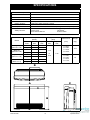
1
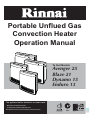
Portable Unflued Gas
Convection Heater
Operation Manual
To Suit Models
Avenger 25
Blaze 21
Dynamo 15
Enduro 13
This appliance shall be installed in accordance with:
• Manufacturer’s Installation Instructions
• Local Regulations and Municipal Building Codes
This appliance must be serviced and repaired by an Authorised Person.
All Rinnai gas products
are A.G.A. certified.
Distributed and serviced in Australia under a Quality
System certified as complying with ISO 9001 by
SAI Global
Rinnai Australia
Operation Manual
TABLE OF CONTENTS
RINNAI WARRANTY ............................................................................................................... ii
ABOUT YOUR PORTABLE CONVECTOR HEATER............................................................. 1
GENERAL DESIGN LAYOUT............................................................................................................ 1
NAVIGATING THE CONTROL PANEL ............................................................................................. 2
NAVIGATING THE REMOTE CONTROL.......................................................................................... 3
FEATURES .............................................................................................................................. 4
IMPORTANT POINTS.............................................................................................................. 5
INSTALLATION ....................................................................................................................... 7
UNPACKING THE APPLIANCE ........................................................................................................ 7
WHAT’S IN THE BOX........................................................................................................................ 7
BEFORE INSTALLING THE APPLIANCE......................................................................................... 7
CHECKING ROOM SIZE................................................................................................................... 8
VENTILATION ................................................................................................................................... 8
GAS CONNECTION .......................................................................................................................... 8
HOW TO OPERATE THE HEATER ........................................................................................ 9
TO TURN THE HEATER ON............................................................................................................. 9
TO ADJUST SET TEMPERATURE................................................................................................... 9
TO TURN THE HEATER OFF ......................................................................................................... 10
USING THE ECONOMY MODE ...................................................................................................... 10
TIMER OPERATION - AVENGER, BLAZE & DYNAMO ...................................................... 11
CLOCK AND DUAL TIMERS........................................................................................................... 11
CHECKING THE CLOCK ................................................................................................................ 11
SETTING THE CLOCK.................................................................................................................... 11
PROGRAMMING TIMER 1.............................................................................................................. 11
PROGRAMMING TIMER 2.............................................................................................................. 12
OPERATING TIMERS ..................................................................................................................... 12
PREHEAT ........................................................................................................................................ 13
USING THE OVERRIDE FUNCTION .............................................................................................. 13
TIMER OPERATION - ENDURO ........................................................................................... 14
OPERATING THE ON TIMER ......................................................................................................... 14
OPERATING THE OFF TIMER ....................................................................................................... 14
LOCK AND SAFETY DEVICES ............................................................................................ 15
USING THE LOCK FUNCTION ....................................................................................................... 15
SAFETY DEVICES .......................................................................................................................... 15
CARE AND MAINTENANCE................................................................................................. 16
AIR FILTERS ................................................................................................................................... 16
REMOVING FILTERS...................................................................................................................... 16
SERVICE ......................................................................................................................................... 16
TROUBLE SHOOTING CHECKLIST............................................................................................... 17
ERROR CODES .............................................................................................................................. 17
SPECIFICATIONS ................................................................................................................. 18
GENERAL SPECIFICATIONS......................................................................................................... 18
WEIGHT AND MEASURES............................................................................................................. 18
CONTACT INFORMATION ................................................................................................... 20
Rinnai Australia
i
Operation Manual
RINNAI WARRANTY
WARRANTY TERMS
The benefits conferred by this warranty are in addition to all other rights and remedies in respect of the product
which you have under the Trade Practices Act and similar State or Territory Laws. Given installation and
application is in accordance with the manufacturers specifications and instructions, Rinnai heating products are
warranted by Rinnai for the cost of labour and components in the event of defects arising from faulty materials
and/or workmanship in accordance with the Warranty Terms, Conditions and Exclusions stated in this document.
TABLE 1 - WARRANTY TERMS
DOMESTIC APPLICATIONS
COMMERCIAL APPLICATIONS
Heat Exchanger
10 years pro rata #
Heat Exchanger
1 year
Fan
5 years
Fan
1 year
All other parts
5 years
All other parts
1 year
Free Labour
5 years
Free Labour
1 year
# Full replacement costs in the first 5 years, reducing 20% per year thereafter
DEFINITIONS OF DOMESTIC AND COMMERCIAL USE
The warranty periods in Table 1 that are allocated under "Domestic Use" are based on the heating requirements
of a typical domestic dwelling. The warranty periods that are allocated under "Commercial Use" are for all other
applications.
WARRANTY CONDITIONS
1. For Flued heaters: All terms of this warranty are effective from date of installation and the attending service
person reserves the right to verify this date by requesting a copy of the certificate of compliance prior to the
commencement of any warranty work. Certificates of compliance must be issued by the installer by law in all
States and Territories of Australia.
2. For Portable Heaters: For portable heaters in 'fixed' (non portable) installations the conditions for Flued
Heaters described in (1) above apply. In all other instances all terms of this warranty are effective from date
of purchase and the attending service person reserves the right to verify this date by requesting a copy of the
purchase receipt prior to the commencement of any warranty work.
3. All Rinnai heating appliances must be installed, commissioned, serviced, repaired and removed in accordance
with the manufacturers installation instructions, current AS 3000, AS 3500 and AS 5601, local regulations and
municipal building codes by persons authorised by local regulations to do so.
4. All appliances must be operated and maintained in accordance with manufacturers operating instructions.
5. The warranty applies only to the components supplied by Rinnai. It does not apply to components supplied by
others, such as, isolating valves, electrical switches, pipework, electrical cables, fuses and, where applicable,
flue systems supplied by others.
6. Where the appliance has not been sited in accordance with the installation instructions or installed such that
normal service access is difficult, a service charge may apply. At the discretion of the attending service person,
if access is deemed dangerous service will be refused. Any work required to gain reasonable access to the
appliance may also be chargeable at the discretion of the attending service person (for example, removal of
cupboards, doors, walls, or the use of special equipment to move components to floor level)
7. Where a failed component is replaced under warranty, the balance of the original appliance warranty will
remain effective. The replacement part or appliance does not carry a new warranty.
8. Rinnai reserve the right to transfer functional components from defective appliances if they are suitable.
9. Rinnai reserve the right to have the installed product returned to the factory for inspection.
WARRANTY EXCLUSIONS
The following exclusions may cause the warranty to become void and may result in a service charge and costs
of parts (if required):
1. Accidental damage and acts of God.
2. Failure due to abuse or misuse, improper maintenance, failure to maintain or improper storage.
3. Failure due to incorrect or unauthorized installations.
4. Failure or damage caused by alterations, service or repair work carried out by persons other than Rinnai
service persons or service agents.
5. Where it is found that there is no fault with the appliance and the issue is related to the installation or is due to
the failure of electric or gas supplies.
6. Subject to any statutory provisions to the contrary Rinnai does not accept:
a. Liability for consequential damage or any incidental expenses resulting from any breach of the warranty,
b. Claims for damage to a building or any other consequential loss either directly or indirectly due to fire
emanating from the appliance or any other faults.
Rinnai Australia
ii
Operation Manual
ABOUT YOUR PORTABLE CONVECTOR HEATER
GENERAL DESIGN LAYOUT
2
1
4
5
4
3
8
5
7
9
11
AVENGER
BLAZE
10
5
2
1
4
8
4
7
3
9
11
10
DYNAMO
5
2
1
4
8
4
7
9
11
ENDURO
10
1
Control panel
6
Gas inlet connection
2
ON / OFF button
Stops and operates the heater.
7
Filter 1
8
Filter 2
3
Remote control receiver window
9
Thermistor
4
Louvre, warm air discharge
10
240v power cord
5
Carry handle(s)
11
Power cord tidy
Rinnai Australia
1
Operation Manual
ABOUT YOUR PORTABLE CONVECTOR HEATER
NAVIGATING THE CONTROL PANEL
28
22
24
26
30
29
19
Avenger Blaze Dynamo
27
21
25
38
36
13
16
14
15
28
2
18
23
20
17
32
30
12
29
Enduro
2
27
37
35
31
34
13
33
12
On / Combustion indicator
When GREEN appliance is in standby, when
RED the burner is operating and when
flashing RED there is a fault.
12
26
Override indicator
Indicates the Override function is in operation.
27
Economy button
Operates the Economy mode.
28
Economy indicator
Indicates Economy function is in operation.
13
Up and Down buttons
Used to adjust set temperature, clock / timer
settings and to operate the Lock function.
14
AM / PM indicators
Indicates AM / PM of clock / timers.
29
Lock indicator
Indicates the Lock function is activated.
15
Digital (Set) display
Displays set temperature and hour digits for
clock / timers.
30
Filter indicator
Indicates that there is a filter blockage.
31
Digital (Temp / Time) display
Displays current room temperature (default),
set temperature, Delay On Timer settings and
error codes.
32
Digital Display Set Temp Indicator
Indicates that the Digital (Temp / Time) display
31 is in the temperature setting mode.
33
Digital Display Room Temp indicator
Indicates that the Digital (Temp / Time) display
31 is in room temperature mode.
34
Digital Display Delay On Timer indicator
Indicates that the Digital (Temp / Time) display
31 is in the timer setting mode.
16
Hour / Minute delineators
Delineates hours / minutes of clock / timers.
17
Digital (Room) display
Displays current room temperature, minute
digits for clock / timers and error codes.
18
Set Times Button
Sets heater to adjust clock / timer functions.
19
Clock set indicator
Indicates heater is in clock setting mode.
20
Timer set indicators
Indicates heater is in timer setting mode.
21
Timer 1 button
Operates Timer programme 1.
35
On Timer button
Sets and or operates the Delay On Timer.
22
Timer 1 indicator
Indicates Timer 1 is in operation.
36
On Timer indicator
Indicates heater is in Delay On Timer mode.
23
Timer 2 button
Operates Timer programme 2.
37
Off timer button
Operates the Off Timer (60 minutes).
24
Timer 2 indicator
Indicates Timer 2 is in operation.
38
Off timer indicator
Indicates heater is in Off Timer mode.
25
Override button
Operates the manual Override function.
Rinnai Australia
2
Operation Manual
ABOUT YOUR PORTABLE CONVECTOR HEATER
NAVIGATING THE REMOTE CONTROL
42
39
ON button
Operates the heater.
40
OFF button
Stops the heater.
41
Up and Down buttons
Used to raise or lower the set temperature.
42
Infra red transmitter
Transmits signal to heater.
43
Battery
The remote control is powered by one CR2032 3V
battery. To replace the battery simply slide open the
battery cradle cover located on the back of the remote
control. When installing a new battery ensure that the
correct polarity (positive uppermost) is observed.
REAR
39
ON
40
OFF
41
OPEN
43
FRONT
CR2032
ONLY use the specified CR2032 3V battery for the remote control
IMPORTANT
The remote control will not function if the heater is in Timer mode.
If the heater is operating in Override mode, using the STANDBY button will cancel
any future timer operations, these will have to be reset manually.
Some fluorescent lights may interfere with the transmission of remote control
signals, in this case changing the position from which you are operating the remote
control may help.
Avoid leaving the remote control in direct sunlight and do not place the remote
control close to the louvres of the heater.
Avoid getting the remote control wet, or dropping it.
Rinnai Australia
3
Operation Manual
FEATURES
FEATURES COMMON TO ALL MODELS
PUSH BUTTON IGNITION
Only one touch of the STANDBY/ON switch is required to operate the
heater.
CHILD LOCK
When the Child Lock is activated all controls other than the
STANDBY/ON switch will be locked. Deactivating the lock releases
the controls. If the lock is activated when the appliance is in
STANDBY, all functions will be locked.
FILTER INDICATOR
When the fan filters become covered with dust, the filter indicator will
flash. The filters should be vacuumed at regular intervals to optimise
heating effectiveness.
ECONOMY FUNCTION
The Economy (ECON) function is an energy saving feature designed
to control the room temperature and prevent discomfort from
overheating.
FEATURES OF AVENGER, BLAZE AND DYNAMO HEATER MODELS
REMOTE CONTROL
For the convenience of operating the heater between STANDBY or
ON, as well as adjusting the temperature up or down while at a short
distance from the heater.
PRE-HEAT
This function will automatically operate the appliance before the
programmed start time of the Timer, in order to heat a room to the
pre-set temperature by the programmed start time.
MEMORY
The micro-computer records selected preset temperatures, the times
programmed into Timers as well as operating the Economy/Auto-Off
and Pre-heat modes, to maintain comfort levels.
DUAL TIMERS
The Dual Timers allows you to program the appliance to come on for
two separate periods each day, one period in the morning and one
period in the evening. The built in Pre-heat Mode brings the room
temperature to the temperature you have selected, by the time
programmed into the Timer.
The Dual Timer feature means that you can "Set and Forget" your
heater. It will turn itself ON or to STANDBY at the times you have
programmed until you cancel the Timer program.
FEATURES OF THE ENDURO HEATER MODEL
MEMORY
The micro-computer records selected preset temperatures, the time
programmed into the On Timer as well as operating the Economy
modes, to maintain comfort levels.
DELAY ON TIMER
The On Timer allows you to program the heater to come on after a
delayed period. This is a particularly useful feature to use overnight
for automatic heating in the morning.
The appliance begins heating a room once it has reached the end of
the delay period selected.
The heater will automatically come on and then remain on until you
manually turn it off.
OFF TIMER
Rinnai Australia
This feature allows you to program the heater to operate for a period
of one hour before it automatically turns off.
4
Operation Manual
IMPORTANT POINTS
The appliance is not intended for use by young children or infirm persons without supervision.
Young children should always be supervised to ensure that they DO NOT play with the appliance.
DO NOT allow children or elderly persons to sleep in the warm air discharge from the heater.DO NOT
sit on this heater
.
DO NOT post or allow children to post articles into the louvres of the heater.
DO NOT cover or place articles on this heater.
DO NOT place articles in front of the louvres
.
DO NOT operate / install this heater in areas where painting is taking place, or in places such as
hairdressing salons, where there may be fluff and dust, and where aerosols are used.
Keep heater away from flammable materials. Combustible materials must not be placed where the
heater could ignite them.
DO NOT spray aerosols near this heater while it is in use. Most aerosols contain butane gas which can
be a fire hazard if used near this heater when it is in use.
Use of aerosols, paint, polishes etc. whilst this heater is in use may also cause unpleasant smells.
Rinnai Australia
5
Operation Manual
IMPORTANT POINTS
It is recommended that a dedicated 240V 10 Amp power point be used with this appliance. DO NOT
use power boards or double adaptors to operate this appliance. Heater MUST NOT be located below a
power socket-outlet
DO NOT place containers of liquid on top of the heater. Water spillage can cause extensive damage to
the appliance and create an electrocution hazard.
.
When the heater is unplugged the for an extended period the clock will stop and will
need to be reset. However programmed ON/OFF times will remain in the memory.
NOTE
Turn the heater OFF after use. DO NOT unplug the heater while it is in operation or while the fans are
still cycling. DO NOT move the heater while it is in operation or while the fans are still cycling.
2
ON
OFF
39
Heat emanating from the front of this appliance may over time affect the appearance of some materials
used for flooring such as carpet, vinyl, cork or timber. This effect may be amplified if the air in the room
contains cooking vapours or cigarette smoke. To avoid this possibility, it is recommended that a mat be
placed in front of the appliance, extending at least 750 mm in front of it.
When the heater is operated for the first time or after long periods of non use a slight odour may be
emitted, this is normal. However if odours persist switch off the appliance and contact Rinnai.
During peak operating periods the filters should be cleaned weekly, however if the Filter warning
indicator illuminates, turn off the appliance immediately and clean filters before further use.
30
Rinnai Australia
6
Operation Manual
INSTALLATION
UNPACKING THE APPLIANCE
Check for damage. If the heater is damaged, DO NOT INSTALL and contact your supplier for advice.
WHAT’S IN THE BOX
The following items should also be included in the carton: This Operation Manual and Remote Control
with Battery.
BEFORE INSTALLING THE APPLIANCE
• Check it is labelled for the correct gas type (see label on rear of heater). Refer to
local gas authority for confirmation of gas type if you are in doubt
IMPORTANT
• The appliance must be installed in accordance with the local gas and electrical
authority regulations.
• A dedicated 240 V Earthed 10 Amp power point must be used with this appliance.
• For information on gas consumption, see data plate on the appliance.
• When using this appliance, ensure that the room is correctly ventilated, in
accordance with the section “VENTILATION” on page 8 and the warning label
located on the appliance. For further information regarding room ventilation contact
Rinnai or your local gas authority.
• DO NOT USE THIS APPLIANCE TO HEAT A BEDROOM, BATHROOM, TOILET,
COMBINED LIVING/SLEEPING AREA OR SAUNA.
• DO NOT CONNECT TO A PROPANE (LPG) GAS CYLINDER INDOORS.
• This appliance must not be
installed where curtains or other
combustible materials could come
into contact with it. In some cases
curtains may need restraining.
50mm
50mm
• This appliance is not designed to
be built in.
50mm
50mm
• This appliance must not be located
below a power socket-outlet.
• If you move house, check the gas
type in the area where you are
moving to.
750mm
• The local gas and electrical
authorities will be able to advise on
local regulations.
The above diagram shows the clearances required
around this heater whilst in operation.
• Heat emanating from the front of this appliance may over time affect the appearance
of some materials used for flooring such as carpet, vinyl, cork or timber. This effect
may be amplified if the air in the room contains cooking vapours or cigarette smoke.
To avoid this possibility, it is recommended that a mat be placed in front of the
appliance, extending at least 750 mm in front of it.
• The appliance is not intended for use by young children or infirm persons without
supervision.
• Young children should be supervised to ensure they do not play with the appliance.
• If the supply cord or gas hose are damaged or require replacing, they must be
replaced by the manufacturer or the manufacturer's agent or similarly qualified
person in order to avoid a hazard.
• The Avenger / Blaze heaters wiegh 12.5 kg and the Dynamo / Enduro heaters weigh
10 kg. Exercise caution when lifting or moving an appliance.
Rinnai Australia
7
Operation Manual
INSTALLATION
CHECKING ROOM SIZE
The heaters MUST NOT be installed in a room smaller than specified, these are:
The Avenger 25 minimum room size 62.5 m³.
The Blaze 21 minimum room size 52.5 m³.
The Dynamo 15 minimum room size 37.5 m³.
The Enduro 13 minimum room size 32.5 m³.
Height
To determine if the intended room meets the minimum size requirements simply multiply the Height x
Width x Depth. For example if the room dimensions are Length 5.3 metres, Width 5.0 metres and
Height 2.4 metres then the volume would be 63.6 m³ and suitable for use with an Avenger 25.
Len
W
g th
t
id
h
A Rinnai VENT kit provides 2 x 250cm² open area vent grills.
VENTILATION
Fixed ventilation must conform to local regulations.
The number and positioning of vents as shown is for illustrative purposes only.
DO NOT use this appliance to heat a bedroom, bathroom, toilet, combined living/sleeping area or
sauna.
If you require more information regarding your local ventilation requirements contact
Rinnai (see back page for contact details) or your local gas regulatory authority.
NEED HELP
GAS CONNECTION
The bayonet plug on the factory fitted flexible hose simply plugs into your bayonet fitting.
Rinnai Australia
8
Operation Manual
HOW TO OPERATE THE HEATER
39
ON
OFF
40
Avenger Blaze Dynamo
41
2
15
17
13
Enduro
12
2
33
31
13
12
TO TURN THE HEATER ON
Before you begin, ensure that the Gas and Power have been connected correctly to the appliance.
To turn the appliance on press the ON/OFF button 2 located on the control panel. For models that
are equipped with a remote control the ON button 39 may also be used.
When pressed the appliance will begin to operate in the following factory preset manner:
•
•
•
The default set temperature will be 22° C 15 .
The current room temperature will be displayed 17 , 31 / 33
The On/Combustion indicator 12 will illuminate Green (steady). Ignition will take 5 ~ 10 seconds.
The ON/Combustion indicator will change to Red (steady) after proper ignition has been
achieved to signify the correct burner operation.
NOTE
When using the appliance for the first time or after long periods of disuse, ignition may
not occur the first time it is operated as there may be air within the pipes. If ignition
does not occur after approximately 30-seconds the unit will cease operation
automatically. If this occurs press the ON/OFF button
twice to restart. For models
that are equipped with a remote control the press the OFF button 40 and then press
the ON button 37 to restart.
The unit may make noises after ignition/extinction. This is due to expansion and
contraction of the heater components and is normal.
The heater will not immediately ignite if the ON/OFF button
is pressed straight after
extinction. After approximately 20 seconds has passed, the heater will automatically
go into ignition mode.
TO ADJUST SET TEMPERATURE
The set temperature may be raised or lowered by use of the Up and Down buttons 13 located on the
control panel. For models that are equipped with a remote control the Up and Down buttons 41 may
also be used.
The following "SET" temperatures can be selected.
• 'L' for continuous combustion on lowest burner setting, without thermostatic control.
• Thermostatic control between 16º C to 26º C in 1º C steps
• 'H' for continuous combustion on highest burner setting, without thermostatic control.
The room temperature will display temperatures between 1º C to 30º C.
Once the temperature is set it will be stored in the microcomputers memory, if the temperature is not
adjusted further it will be available as the initial setting when the appliance is next used.
Rooms may not arrive at the "SET" temperature due to the size and construction of
the room, location of the appliance or external temperatures.
NOTE
If the appliance does not ignite then the pre-set temperature may already be higher
than the actual room temperature.
Rinnai Australia
9
Operation Manual
HOW TO OPERATE THE HEATER
39
ON
OFF
40
Avenger Blaze Dynamo
41
2
28
27
15
17
13
Enduro
12
2
28
33
27
31
13
12
TO TURN THE HEATER OFF
To turn the heater off while it is in operation press the ON/OFF button 2 located on the control panel.
For models that are equipped with a remote control the OFF button 40 may also be used.
The On/Combustion indicator
NOTE
12
will go out.
After the On/Combustion indicator 12 has gone out, the appliance fan will continue
to cycle for several minutes. This is to lower the temperature within the appliance and
is normal. DO NOT disconnect the power during this time.
USING THE ECONOMY MODE
As a room is warmed, the walls and ceilings are also warmed, making one feel a little warmer than
when the ceilings and walls were cold, even though the room temperature is the same. The Economy
mode prevents discomfort from overheating and saves energy.
When the Economy mode is selected the appliance will heat the room. Once the set temperature has
been maintained for a period of 30 minutes, the comfort control system will progressively lower the
set temperature by 2°C over a period of 60 minutes.
To operate the heater in Economy mode, press the Economy button 27 while the appliance is in
operation 27 . The Economy indicator 28 will illuminate to show the appliance is now operating in
Economy mode.
To cancel Economy mode press the Economy button 27 and the Economy indicator
to show that the economy mode has now been cancelled.
Rinnai Australia
10
28
will go out
Operation Manual
TIMER OPERATION - AVENGER, BLAZE & DYNAMO
CLOCK AND DUAL TIMERS
The setting of the Clock and programming of the Timers is
done via the Set Times button 18 . Each press of this button
will cycle the appliance through the available clock setting and
timer programming modes that are available.
CHECKING THE CLOCK
18
One press of the Set Times button
time that the clock is set to.
18
displays the current
SETTING THE CLOCK
Two presses of the Set Times button 18 selects the clock
setting mode, allowing the current time to be adjusted. When
in this mode the ‘Clock’ indicator 19 is illuminated
The factory default clock time is PM 12:00.
Press the Up or Down buttons
desired time.
13
to adjust the clock to the
18
13
16
14
15
19
17
Pressing and holding either the Up or Down buttons 13 will
scroll digits, at first by minute 17 intervals and then by hour
15 intervals. When adjusting the time ensure that the correct
AM or PM 14 setting is observed.
To lock in the new clock time and exit the Clock and Timer setting mode without
altering the Timer 1 or Timer 2 settings press the Set Times button 18 five times.
NOTE
PROGRAMMING TIMER 1
Three presses of the Set Times button 18 selects the Timer 1
‘On’ programming mode which allows adjustment of the time
when the heater switches ‘On’ (or starts). The Timer 1 and On
indicators 20 are illuminated.
The factory default Timer 1 ‘On’ time is AM 06:00. Press the Up
or Down buttons 13 to adjust the Timer 1 ‘On’ time.
18
15
Pressing and holding either the Up or Down buttons 13 will
scroll digits, at first by minute 17 intervals and then by hours
15 intervals. When adjusting the time ensure that the correct
AM or PM 14 setting is observed.
13
16
14
20
17
Four presses of the Set Times button 18 selects the Timer 1
‘Off’ programming mode which allows adjustment of the time
when the heater switches ‘Off’ (or stops). The Timer 1 and Off
indicators 20 are illuminated.
The factory default Timer 1 ‘Off’ time is AM 09:00. Press the Up
or Down buttons 13 to adjust the Timer 1 ‘Off’ time.
Pressing and holding either the Up or Down buttons 13 will
scroll digits, at first by minute 17 intervals and then by hours
15 intervals. When adjusting the time ensure that the correct
AM or PM 14 setting is observed.
NOTE
18
13
16
14
15
17
20
To lock in the new Timer 1 on and off timer program and to exit the Clock setting and
Timer programming mode without altering the Timer 2 settings press the Set Times
button 18 three times.
Rinnai Australia
11
Operation Manual
TIMER OPERATION - AVENGER, BLAZE & DYNAMO
PROGRAMMING TIMER 2
Five presses of the Set Times button 18 selects the Timer 2
‘On’ programming mode which allows adjustment of the time
when the heater switches ‘On’ (or starts). The Timer 2 and On
indicators 20 are illuminated.
The factory default Timer 2 ‘On’ time is AM 06:00. Press the Up
or Down buttons 13 to adjust the Timer 2 ‘On’ time.
18
15
Pressing and holding either the Up or Down buttons 13 will
scroll digits, at first by minute 17 intervals and then by hours
15 intervals. When adjusting the time ensure that the correct
AM or PM 14 setting is observed.
13
16
14
20
17
Six presses of the Set Times button 18 selects the Timer 2
‘Off’ programming mode which allows adjustment of the time
when the heater switches ‘Off’ (or stops). The Timer 2 and Off
indicators 20 are illuminated.
The factory default Timer 2 ‘Off’ time is AM 09:00. Press the Up
or Down buttons 13 to adjust the Timer 2 ‘Off’ time.
Pressing and holding either the Up or Down buttons 13 will
scroll digits, at first by minute 17 intervals and then by hours
15 intervals. When adjusting the time ensure that the correct
AM or PM 14 setting is observed.
Seven presses of the Set Times button
appliance to normal operation.
18
18
13
16
14
15
20
17
will return the
OPERATING TIMERS
Turn the appliance on by pressing the ON/OFF button
button 39 of the remote control.
2
located on the control panel or the ON
Set the desired temperature and select the economy mode if required.
28
22
24
26
39
ON
OFF
40
27
21
23
41
2
18
25
20
12
Timer 1 and Timer 2 may be operated together or individually.
NOTE
The heater will continue to operate under control of the timers until timer operation is
cancelled.
To select operation by Timer 1 press the Timer 1 21 button. The Timer 1 indicator 22 will illuminate
steady to show that the heater is waiting for the programmed ‘on’ time to be reached.
To select operation by Timer 2 press the Timer 2 23 button. The Timer 2 indicator 24 will illuminate
steady to show that the heater is waiting for the programmed ‘on’ time to be reached.
The heater automatically turns itself on once the ‘on’ time of the selected timer(s) is
reached and the associated Timer indicator 22 or 24 will flash while the heater is
operating under timer control.
When the ‘off’ time of the selected timer is reached the heater will automatically turn off and the Timer
indicator will illuminate steady to indicate the heater is waiting for the next programmed timer cycle to
begin.
To cancel timer(s) operation press the associated timer button(s). The indicator will go out to signify
that the heater is now operating under manual control.
Rinnai Australia
12
Operation Manual
TIMER OPERATION - AVENGER, BLAZE & DYNAMO
PREHEAT
This function operates automatically in
conjunction with the Timers. When a Timer is
selected, the heater may operate anywhere
within an hour prior to the programmed
starting time of a Timer.
This function is called Pre-heat since it
ensures the room reaches the desired
temperature by the On Time programmed
into the Timer(s). The room temperature is
sensed one hour before the programmed On
Time.
The temperature differential at the time of sensing the room temperature combined with the data from
previous operation governs exactly how long before the programmed On time the micro-computer will
operate the heater and ignite the burner.
USING THE OVERRIDE FUNCTION
This function is used to manually override the current operation of the heater. For example: if the
heater is between the finishing and starting times of a timer program and the Override button is
selected, then the heater will begin to operate and heat the room.
22
24
26
39
ON
OFF
40
21
23
41
2
18
25
20
12
The heater must be between the finishing and starting times of a timer program for the Override to
function to work. Either of the Timer indicators 22 or 24 will be illuminated and the Combustion
indicator 12 is illuminated green when this is the case. If the Overrrided button 25 is pressed the
Override indicator 26 will flash to show that the heater is now operating in override mode. The heater
will now start and full manual control will now be available.
To cancel override and to return to Timer operation press the Override button 25 again. The Override
indicator 26 will go out and the and Combustion indicator 12 will be illuminated green to confirm that
timer operation has been restored and that the heater is awaiting a timer operation to begin. If the
Override button 25 is not pressed the heater will remain on until the next programmed Off time setting
is reached.
If the ON/OFF button
or the OFF button 40 on the remote control are pressed the
heater will be turned off and the timer programs will not operate.
NOTE
Rinnai Australia
13
Operation Manual
TIMER OPERATION - ENDURO
OPERATING THE ON TIMER
The Delay On Timer allows you to delay the start time of the heater for up to 24 hours.
36
2
35
31
34
13
12
To operate, press the On Timer button 35 . The On Timer indicator 36 will illuminate and the
Combustion indicator 12 will be illuminated green to confirm that the heater is awaiting for the Delay
‘on’ time period to pass before commencing operation. The Delay On timer indicator 34 will also
illuminate and the current Delay On Time period will be displayed on the Digital (Temp / Time) display
31 for 60 seconds. Whilst displayed, the Delay On time can be adjusted by pressing the Up or Down
buttons 13 . A delay time of up to 9½ hours can be set in increments of 30 minutes and a delay time
of up to 24 hours in increments of 60 minutes.
When the programmed Delay ‘On’ time period has passed, the heater will automatically begin
operation.
The heater will continue to operate until operation is cancelled by pressing the ON/
OFF button
or by pressing the Off Timer button 37 .
NOTE
The delay ‘On’ time last programmed is stored in the memory and will be the default
until it is re-adjusted.
If the On Timer button 35 is pressed whilst the heater is in operation the On Timer will
override manual operation.
OPERATING THE OFF TIMER
The Off Timer allows you to set a 60 minute delay before the heater will automatically turn off.
38
2
37
31
13
33
12
To operate, press the Off Timer button 37 . The Off Timer indicator 38 will illuminate and the
Combustion indicator 12 will be illuminated red to confirm that the heater will continue operation until
the Delay ‘off’ time period has passed after which it will stop. The Delay Off time is 60 minutes. When
this time has passed, the heater will automatically stop operation and the Off Timer indicator 38 will
flash.
During Off Timer operation full manual control of the heater is available..
After the Off timer operation is completed the ON/OFF button
heater.
NOTE
twice to restart the
The Off Timer and On Timers work independently of each other. However, if both
timers are operating and the Delay On time period is 30 minutes, the Delay Off Timer
will override the Delay On Timer.
Rinnai Australia
14
Operation Manual
LOCK AND SAFETY DEVICES
USING THE LOCK FUNCTION
29
The Lock function will avoid accidental operation and
prevent small children from altering the heater settings.
To Activate the Lock
To activate the Lock function press both the Up and
Down buttons 13 simultaneously for 3 seconds. The
function is activated immediately and the Lock indicator
29 will be illuminated.
13
12
29
To Deactivate the Lock
To deactivate the Lock function press both the Up and
Down buttons 13 simultaneously for 3 seconds. The
Lock indicator 29 will go out to show that the Lock
function is no longer active. The Lock function can be
deactivated at any time in this manner.
Enduro
2
13
NOTE
Avenger Blaze Dynamo
2
12
If the Lock function is activated whilst the heater is in operation or in Timer mode, all
controls other than the ability to switch the appliance OFF with the ON/Off button
or for models with a remote control the OFF button 40 will be locked until the Lock is
deactivated. Timer operation will not be affected.
If the lock function is activated whilst the appliance is in the off position, all controls
will be locked until the Lock function is de-activated.
If the appliance is switched off whilst the Lock function is activated, all controls will
be locked until the Lock function is de-activated.
Lock programming (activated or de-activated) is stored in the appliance memory.
Unplugging the appliance from the power supply has no effect on Lock programming.
SAFETY DEVICES
Over heat switch
When the heater gets too hot during operation (for example when the filters or air outlet louvres are
blocked) this device turns the gas off automatically.
Electrical fuse
The electrical circuits are protected by a fuse.
Flame failure sensor
This device automatically cuts off the gas supply to the heater in the event of a gas failure.
Oxygen depletion sensor
If the oxygen level in the room drops below a pre-set limit, this device cuts the gas supply to the heater.
Tilt switch
If the heater is knocked over, the tilt switch will cut the gas supply. The fan keeps cycling.
Power failure
In the event of a power failure or power cut, the gas valves will automatically close.
Rinnai Australia
15
Operation Manual
CARE AND MAINTENANCE
Your heater needs very little maintenance, but the following information will help you to keep it looking
good and working efficiently.
Unplug before cleaning.
IMPORTANT
All parts of the heater can be cleaned using a soft, damp cloth.
DO NOT use solvents to clean any parts.
DO NOT spray aerosols in the vicinity of the heater whilst in operation.
DO NOT place articles on or against this heater.
DO NOT store flammable materials near this heater.
AIR FILTERS
Dusty filters reduce heating effectiveness.
DO NOT wait for Filter indicator
cleaning filters.
30
to come on before
DO NOT use the heater with the filter warning lamp on. This
may cause it to overheat.
8
7
REMOVING FILTERS
Filters require cleaning at least once a week during the heating
season to prevent blockages.
For cleaning Filter 1 7 , undo and remove the retaining screw
(ensure the retaining screw is stored in a safe place).
Carefully lift filters up then backwards to remove from locating
tabs.
With the careful use of a vacuum cleaner, gently remove any
contaminates such as dust and lint.
Replace filters by carefully repositioning the location tabs and
fasten in place with the retaining screw.
Filter 2 8 (the small filter) should be left in position for
cleaning, carefully use a vacuum cleaner to remove any
contaminates such as dust and lint.
8
7
SERVICE
Rinnai recommend that this appliance and installation be
inspected and serviced every 2 years.
If the power supply cord or any other component of the heater are damaged, they must be replaced
by Rinnai or a suitably qualified person.
Any service or repair work should only be carried out by an authorised person. Rinnai has service and
spare parts departments nationally see back cover for contact details.
Service calls for general cleaning, maintenance and wear and tear are not necessarily
covered under the warranty. Service calls of this nature may be chargeable.
NOTE
Rinnai Australia
16
Operation Manual
CARE AND MAINTENANCE
TROUBLE SHOOTING CHECKLIST
Not plugged in or turned off.
Mains power failure.
(Initial Install) Air in gas pipe.
Air in hose
Room too large
Dust on air filters
Louvre obstructed
Air filter blocked
Gas escape
Gas supply turned off.
Lock set.
On Timer is set.
Flat batteries.
Takes a long time to
warm the room
Remote control
doesn’t work
Smell of gas
Probable
Cause
Filter Indicator
is illuminated
Combustion stops
during operation
No Display
Fault
Condition
Burners fail to ignite
Use the following chart to help determine whether a service call is required, however if you are unsure
about the way your heater is operating, contact Rinnai or your local agent.
Possible Remedy
Plug in power cord and turn power on.
Re-ignition, when power restored, page 9.
Installer to purge air from gas supply.
Repeat Ignition procedure page 9.
Check with retailer.
Clean the air filters (Weekly).
Remove obstruction
Clean the air filters (Weekly).
Isolate gas supply, call Rinnai service.
Turn gas supply on at the meter or cylinder.
Cancel Lock as described on page 15.
Cancel timer by using the override page 13.
Replace remote control battery.
ERROR CODES
Your heater is also fitted with self diagnostic electronics that monitor the appliance during start-up and
operation. Should a fault occur the heater will shut down and the cause fault will be indicated by a pair
of flashing digits in the Digital display 17 or 31 depending on the model and the On/Combustion
indicator 12 will also flash Red. Refer to the table below for probable cause and the suggested
remedy
Code
Probable Cause
Suggested Remedy
Press the ON/OFF button
twice to reset heater.
Ensure appliance is level & upright. Service call if repeated.
Clean filters. Ventilate room. Service call if repeated.
Check gas supply is turned on, turn the heater OFF and then
ON again. If the heater fails to ignite after 4 attempts a
Service call will be required.
As above.
Service call.
Clean filters. If error continues a service call will be required.
Lower room temp to below 40°C.
Service call.
Service call.
Service call.
Service call.
Service call.
Service call.
Service call.
Service call.
Service call.
00
Mains power failure during operation
03
10
Tilt switch activated
Oxygen shortage
11
Ignition failure
12
13
14
16
18
31
32
33
34
62
70
71
72
Incomplete combustion
Combustion control faulty
Filter Blockage / Overheat
Room overheat
Temperature sensor faulty
Room temperature sensor faulty
Overheat temperature sensor faulty
Overheat temperature sensor faulty
Overheat temperature sensor faulty
Faulty fan motor
ON/OFF switch faulty
Solenoids faulty
Flame detection circuit fault
73
Communication error
Rinnai Australia
Press the ON/OFF button
call if repeated.
17
2
twice to reset heater. Service
Operation Manual
SPECIFICATIONS
GENERAL SPECIFICATIONS
General Description:
Portable Gas Convector Heaters.
Gas Control:
Electronic control
Burner
Surface Combustion Burner
Gas Connection:
3/8” MI BSP into 1.5 metre flexible gas hose with bayonet connection
Convection Fan:
Multi Speed Fan
Ignition System:
Continuous spark electronic ignition
Operation:
Push button electronic, remote control (Avenger, Blaze, Dynamo)
Over Heat Switch
Electric Fuse
Flame Failure Sensor
Safety Devices:
Oxygen Depletion Sensor
Tilt Switch
Power Failure
WEIGHT AND MEASURES
Model
Avenger 25
(RCE 671 TR)
Blaze 21
(RCE 571 TR)
Dynamo 15
(RCE 471 TR)
Enduro 13
(RCE 371 H)
Gas Input
(MJ/hr)
Supply Pressure
(kPa)
Burner
Rate
Natural
Gas
Propane
Gas
Low
8.5
8.5
High
25.0
25.0
Low
8.5
8.5
High
21.0
21.0
Low
8.5
8.5
High
15.0
15.0
Low
8.5
8.5
High
13.0
13.0
Natural
Gas
Propane
Gas
1.13
to
2.75
Dimensions
Weight
(mm)
(Kg)
A = 610
B = 482
C = 239
D = 202
12.5
A = 487
B = 492
C = 244
D = 125
10
2.75
D
C
A
B
Rinnai Australia
18
Operation Manual
Rinnai Australia
19
Operation Manual
CONTACT INFORMATION
Australia Pty. Ltd.
Internet: www.rinnai.com.au E-mail: [email protected]
ABN 74 005 138 769
Head Office
National Help Lines
10-11 Walker Street,
Braeside, Victoria 3195
P.O. Box 460
Tel: (03) 9271 6625
Fax: (03) 9271 6622
Sales & Service
Tel: 1300 555 545* Fax: 1300 555 655*
Spare Parts & Technical Info
Tel: 1300 366 388* Fax: 1300 300 141*
*Cost of a local call Higher from mobile or public phones.
U???-????
Rinnai has a Service and Spare Parts network with personnel who are fully trained
and equipped to give the best service on your Rinnai appliance. If your appliance
requires service, please call our Hot Water Service Line. Rinnai recommends that
this appliance be serviced every 2 years.
20
BARCODE
Printed in Japan YYYY.MM
㪇㪈㪉㪊㪋㪌㪍㪎㪏㪐㪇㪈㪉㪊
RA TSD06-008 Issue 2.0 28/08/07