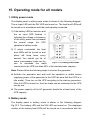
1
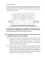
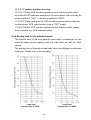
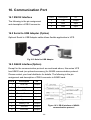
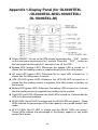
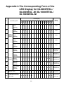
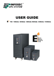
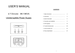
PARAGON SERIES
USER MANUAL
OL1-10KVA UPS
Uninterruptible Power Supply
Contents
1. Safety and EMC Instructions......................................................................................... 1
1.1 Installation .................................................................................................................... 1
1.2 Operation ...................................................................................................................... 2
1.3 Maintenance, Servicing and Faults............................................................................. 2
1.4 Transport ...................................................................................................................... 2
1.5 Storage.......................................................................................................................... 3
1.6 Standars........................................................................................................................ 4
2. Description of Commonly Used Notations .................................................................. 5
3. Introduction -OL1000TEXL/OL1000EXL-M/OL2000TEXL/OL2000EXL-M/
OL3000TEXL/OL3000EXL-M...................................................................................... 6
4. System Description........................................................................................................ 7
5. Connection and Operation for OL1000TEXL/OL1000EXL-M/OL2000TEXL
/OL2000EXL-M/ OL3000TEXL/OL3000EXL-M ........................................................... 9
6. Trouble Shooting.......................................................................................................... 13
7. Maintenance ................................................................................................................. 14
7.1 Operation .................................................................................................................... 14
7.2 Storage........................................................................................................................ 14
8. Technical data .............................................................................................................. 15
8.1 Electrical Specifications ............................................................................................ 15
8.2 Operating Environment ............................................................................................. 15
8.3 Typical Battery Back-up Time ................................................................................... 15
8.4 Dimensions and Weights........................................................................................... 16
9. Product Specification and PerformanceOL6000TEXL/OL6000EXL-M/OL10000TEXL/OL10000EXL-M ................................ 17
9.1 Gerenal Specification................................................................................................. 17
9.2 Electrical Performance .............................................................................................. 17
9.2 Operating Environment ............................................................................................. 18
10. Installation .................................................................................................................. 19
10.1 Unpacking and Inspection....................................................................................... 19
10.2 Input and Output Power Cords and Protective Earth Ground Installation.......... 19
10.3 Operating Procedure for Connecting the Extended Backup Time Model UPS
with the External Battery ......................................................................................... 21
10.4 Parallel Operation..................................................................................................... 23
11. Operation and Maintenance ...................................................................................... 29
12. Battery Maintenance .................................................................................................. 29
13. Notes for Battery Disposal and Battery Replacement ........................................... 30
14. Trouble Shooting........................................................................................................ 31
15. Operating Mode for all Models.................................................................................. 33
16. Communication Port .................................................................................................. 36
17. Software for All Models ............................................................................................. 37
Appendix 1-Display Panel(for OL6000TEXL/OL6000EXL-M/
OL10000TEXL/OL10000EXL-M) ............................................................................ 38
Appendix 2-The Corresponding Form of The LED Display for OL6000TEXL/
OL6000EXL-M/OL10000TEXL/OL10000EXL-M ....................................................... 39
Appendix 3-Back Panel ................................................................................................. 41
1. Safety and EMC instructions
Please read carefully the following user manual and the safety instructions
before installing the unit or using the unit!
1.1 Installation
★ Condensation may occur if the UPS is moved directly from a cold to a
warm environment. The UPS must be absolutely dry before being
installed. Please allow an acclimatization time of at least two hours.
★ Do not install the UPS near water or in damp environment.
★ Do not install the UPS where it would be exposed to direct sunlight or
near heat.
★ Do not block ventilation openings in the UPS’s housing.
★ Do not connect appliances or items of equipment which would
overload the UPS (e.g. laser printers, etc) to the UPS outlet sockets.
★ Place cables in such a way that no one can step on or trip over them.
1.1.1 Installation for OL1000TEXL/OL1000EXL-M/OL2000TEXL/
OL2000EXL-M/OL3000TEXL/OL3000EXL-M
★ Socket-outlets and socket of batteries are earthed by the input
power cord, please insert the power cord into mains socket before
using of UPS.
★ Connect the UPS only to an earthed shockproof socket outlet.
★ The building wiring socket outlet (shockproof socket outlet) must be
easily accessible to close to the UPS.
★ This is operator installable.
1.1.2 Installation for OL6000TEXL/OL6000EXL-M/OL10000TEXL/
OL10000EXL-M
★ UPS has provided earthed terminal, in the final installed system
configuration, equipotential earth bonding to the external UPS
battery cabinets.
-1-
★ An integral single emergency switching device which prevents
further supply to the load by the UPS in any mode of operation
should be provided in the building wiring installation.
★ An appropriate disconnect device as short-circuit backup protection
should be provided in the building wiring installation.
★ For three-phase equipment connection to an IT power system, a
four-pole device which disconnect all phase conductors and the
neutral conductor should be provided in the building wiring
installation.
★ This is permanently connected equipment , it must be installed by
qualified maintenance personnel.
★ Earth connection essential before connecting to the building wiring
terminal.
1.2 Operation
★ Do not disconnect the mains cable on the UPS or the building wiring
socket (grounded shockproof socket) during operation as this would
remove the ground to the UPS and of all connected loads.
★ The UPS output socket or output terminal block may be electrically
lived even if the UPS system is not connected to the building wiring
terminal.
★ In order to fully disconnect the UPS, first press the Standby button, then
disconnect the mains lead.
★ Ensure that no liquid or other foreign objects can enter the UPS.
★ The UPS can be operated by any individuals with no previous
experience.
1.3 Maintenance, servicing and faults
★ The UPS operates with hazardous voltages. Repairs may be carried
out only by qualified maintenance personnel.
★ Caution - risk of electric shock. Even after the unit is disconnected from
the mains power supply (building wiring socket), components inside
-2-
the UPS are still connected to the battery which are potentially
dangerous.
★ Before carrying out any kind of service and/or maintenance,
disconnect the batteries. Verify that no current is present and no
hazardous voltage exists in the capacitor or BUS capacitor terminals.
★ Batteries must be replaced only by qualified personnel.
★ Caution - risk of electric shock. The battery circuit is not isolated from
the input voltage. Hazardous voltages may occur between the battery
terminals and the ground. Verify that no voltage is present before
servicing!
★ Batteries have a high short-circuit current and pose a risk of shock
Take all precautionary measures specified below and any other
measures necessary when working with batteries:
- remove all jewellery, wristwatches, rings and other metal objects
- use only tools with insulated grips and handles.
★ When changing batteries, replace with the same quantity and the same
type of batteries.
★ Do not attempt to dispose of batteries by burning them. It could cause
explosion.
★ Do not open or destroy batteries. effluent electrolyte can cause injury
to the skin and eyes. It may be toxic.
★ Please replace the fuse only by a fuse of the same type and of the
same amperage in order to avoid fire hazards.
★ Do not dismantle the UPS, except the qualified maintenance
personnel.
1.4 Transport
★ Please transport the UPS only in the original packaging (to protect
against shock and impact).
1.5 Storage
★ The UPS must be stockpiled in the room where it is ventilated and dry.
-3-
1.6 Standards
■ For OL1000TEXL/OL1000EXL-M/OL2000TEXL/OL2000EXL-M/
OL3000TEXL/OL3000EXL-M
* Safety
IEC/EN 62040-1-1
* EMI
Conducted Emission...........................:IEC/EN 62040-2
Category C1
Radiated Emission..............................:IEC/EN 62040-2
Category C1
Harmonic Current................................:IEC/EN 61000-3-2
Voltage Fluctuation and Flicker............:IEC/EN 61000-3-3
*EMS
ESD.................................................:IEC/EN 61000-4-2
Level 4
RS...................................................:IEC/EN 61000-4-3
Level 3
EFT..................................................:IEC/EN 61000-4-4
Level 4
SURGE............................................:IEC/EN 61000-4-5
Level 4
Low Frequency Signals...................:IEC/EN 61000-2-2
■ For OL6000TEXL/OL6000EXL-M/OL10000TEXL/OL10000EXL-M
* Safety
IEC/EN 62040-1-1
* EMI
Conducted Emission...........................:IEC/EN 62040-2
Category C3
Radiated Emission..............................:IEC/EN 62040-2
Category C3
*EMS
ESD.................................................:IEC/EN 61000-4-2
Level 4
RS...................................................:IEC/EN 61000-4-3
Level 3
EFT..................................................:IEC/EN 61000-4-4
Level 4
SURGE............................................:IEC/EN 61000-4-5
Level 4
Low Frequency Signals....................:IEC/EN 61000-2-2
Warning: This is a product for commercial and industrial application in
the second environment-installation restrictions or additional measures
may be needed to prevent disturbances.
-4-
2. Description of commonly used notations
Some or all of the following symbols may be used in this manual. It is
advisable to familiarize yourself with them and understand their meaning.
Symbol and Explanation
Symbol
Explanation
Alert! Pay special attention
Caution! high voltage
I
Turn on the UPS
Turn off the UPS
Idle or shut down the UPS
Altermating current source(AC)
Direct current source(DC)
Protective ground
Alarm silence
Overload indication
Battery
Recycle
Do not dispose with ordinary trash
-5-
3. Introduction – OL1000TEXL/OL1000EXL-M/
OL2000TEXL/OL2000EXL-M/
OL3000TEXL/OL3000EXL-M
The On-Line-Series is an uninterruptible power supply incorporating double
convertion technology. It provides failsafe power to the connected
equipment.
The double convertion design eliminates all power disturbances. A rectifier
converts the alternating current from the socket to direct current. This direct
current charges the batteries and powers the inverter. The inverter generates
a sinusoidal AC voltage to power the loads.
In the event of power failure, the maintenance-free batteries power the
inverter.
This manual covers the UPS units listed below.
Model No.
Type
Model No.
OL1000TEXL
OL2000TEXL
Type
OL1000EXL-M
Standard
OL2000EXL-M
OL3000TEXL
OL3000EXL-M
-6-
Extended
backup time
4. System Description
Figure 1: Display Panel
Switch
Function
Turn on UPS system:
By pressing the ON-Switch “I” the UPS system is turned on.
ON - Switch
OFF-Switch
Deactivate audible:
By pressing this switch an acoustic alarm can be
deactivated.
Utility power is normal, the UPS system switches to Standby
mode by pressing OFF-Switch “ “. It is then switched to
Bypass and the inverter is off. At this time, the output
sockets are supplied with voltage via the bypass if the utility
power is available.
Display
Function
1:
FAULT LED
The red fault LED lights up and an acoustic warning
signal is issued continuously when the UPS system is in
fault condition. Press the Standby switch in order to turn
off the warning tone.
12:
BYPASS LED
The orange-coloured BYPASS LED lights up when the
UPS system is supplying voltage provided by the utility
power via the bypass.
-7-
13:
BATTERY LED
The green-coloured BATTERY-LED lights up when the
utility power has failed and the inverter is being powered
by the batteries.
14:
UPS ON LED
The green-coloured UPS ON LED lights up if the UPS
system is supplying voltage provided by the utility power
via the inverter.
The green AC INPUT LED lights up if utility voltage is
applied to the UPS input.
15:
AC INPUT LED
AC INPUT LED blinks when the phase and neutral
conductor have been reversed at the input of the UPS
system.
If AC INPUT LED and BATTERY-LED light up, the utility
power supply is out of tolerance.
Display
LOAD and
BATTERY
CAPACITY
LEDs
Function
2-6 LEDs show the load of the UPS system (+/-5%
Tolerance):
LED 2: 0-30%
LED 3: 31%-50%
LED 4: 51%-70%
LED 5: 71%-95%
LED 6: 96%-105%
7-11 LEDs show the load of the batteries (+/-5%
Tolerance):
LED 7: 0-25 %
LED 8: 26%-50%
LED 9: 51%-75%
LED 10: 76%-95%
LED 11: 96%-100%
-8-
5. Connection and Operation for OL1000TEXL/
OL1000EXL-M/OL2000TEXL/OL2000EXL-M/
OL3000TEXL/OL3000EXL-M
The system must be installed and wired only by licensed electricians in
accordance with applicable electrical regulations!
When installing the electrical wiring, please note the nominal amperage of
your incoming feeder.
5.1 Inspection:
Inspect the packaging carton and its contents for damage. Please inform
the freight carrier immediately if you find signs of damage.
Please keep the packaging in a safe place for future use.
Note: Please ensure that the incoming feeder is isolated and secured to
prevent it from being switched back on again.
5.2 Connection:
5.2.1 UPS Input Connection
If the UPS is connected via the power cord, please use a proper wired
and grounded socket. Pay attention to the capacity of the socket: over
10A for OL1000TEXL, OL1000EXL-M & OL2000TEXL, over 16A for
OL2000EXL-M& OL3000TEXL/OL3000EXL-M.
5.2.2 UPS Output Connection
The output of OL1000TEXL, OL1000EXL-M and OL2000TEXL are
socket-types only. Simply plug the load power cord to the output sockets
to complete connection.
-9-
Model No.
Output Socket (pcs)
Terminal Block
OL1000TEXL
4
Not Available
OL1000EXL-M
4
Not Available
OL2000TEXL
6
Not Available
OL2000EXL-M
4
Available
OL3000TEXL
4
Available
OL3000EXL-M
4
Available
Besides output sockets, the OL2000EXL-M and OL3000TEXL/
OL3000EXL-M units have a terminal block available for output as well.
The terminal block can be wired using the following procedure:
1. Remove the terminal block cover.
2. Use AWG14 or 2.1mm2 wires for wiring configuration.
3. Upon completion of the terminal block wiring, check to ensure the wires
are securely fastened.
4. Replace the terminal block cover.
Figure 2: Terminal Blcok Connectiondiagram of
OL2000EXL-M and OL3000TEXL/ OL3000EXL-M
5.2.3 Computer Connection:
Connect your computer to the sockets of the UPS system following the
above diagram.
Caution!
Do not connect equipment which would overload the UPS system (e.g.
laser printers)
-10-
5.3 Charge Battery:
Fully charge the batteries of the UPS system by leaving the UPS system
connected to the utility power for 1-2 hours. You may use the UPS system
directly without charging it but the battery run time may be shorter than
the listed run times.
5.4 Power on the UPS:
5.4.1 Utility power present:
Press “Power On” button for more than 1 second to turn on the UPS. The
UPS will go into self-test status first. The UPS will go into the inverter
mode next. At this time, the AC Input, UPS On, Load Capacity, and
Battery Capacity LEDs will light up.
5.4.2 Utility power not present:
Even without the utility power connected to the UPS, the UPS still can be
turned on by just simply pressing “Power On” button for more than 1
second. The UPS will go into self-test status first. The UPS will then go
into the inverter mode. At this time, Battery, UPS On, Load Capacity, and
Battery Capacity LEDs will light up.
5.5 Test Function:
Test the function of the UPS system by either pressing the “Power On”
button or disconnecting the input of the UPS system from the power
supply.
5.6 Power off the UPS:
5.6.1 In Inverter Mode:
Press “ “ button continuously for more than 1 second to turn off the UPS.
Then the UPS will enter self-test status. After finishing the self-test, the
UPS will enter bypass mode and the AC Input LED and Bypass LED will
light up. At this time, the UPS might provide output. Disconnect the utility
power to turn off the output.
-11-
5.6.2 In Battery Mode:
Press “ “ button for more than 1 second to turn off the UPS. Then the
UPS enter into self-test status. After finishing the self-test, the UPS will be
turned off completely.
5.7 Audible Alarm Mute Function:
To disable the alarm in battery mode, you may press “Power On” button
for more than 1 second to clear it. However, the alarm will be
automatically restored when the battery is low to indicate shutdown is
imminent.
5.8 Operation Procedure of External Battery for extended run
times (“EXL-M” Models)
The units with CE markings—
(a) Use the battery pack with the following voltages: 36VDC for
OL1000TEXL(3 pcs of 12V batteries), 96VDC for OL2000TEXL /
OL3000TEXL (8 pcs of 12V batteries). Do not connect any other
quantities or voltages of batteries.
(b) One end of the external battery cord is a plug for connecting the UPS
and the other end has a plug for connecting the battery cabinet
(c) Do not connect a load to the UPS yet. Connect the power cord of the
UPS to the utility supplied power.
(d) Connect the plug of the external battery cord to the external battery
socket on the rear panel of the UPS to complete the connection and
the UPS will automatically charge the battery pack.
The Caution!
The output sockets of the UPS system may still be electrically charged even
if the power supply system has been disconnected or the Bypass switch is in
the “OFF” position.
-12-
6. Trouble Shooting
If the UPS system does not operate correctly, please attempt to solve the
problem using the table below.
Problem
Possible cause
No indication, no warning tone
even though system is
No input voltage
connected to mains power
supply
Remedy
Check building wiring socket
and input cable.
AC INPUT LED blinks
Phase and neutral
conductor at input of
UPS system are
reversed
Check the phase and neutral at
the building wiring socket..
AC INPUT LED blinks and
BATTERY-LED lights up
Input power and/or
frequency are out of
tolerance
Check the input power source
AC INPUT and BYPASS LED
light up even though the
power supply is available
Inverter not switched
on
Press On-Switch “I”
UPS ON LED lights up, and
audible alarm sounds 1 beep
every 4 seconds
Mains power supply
has failed
Switching to battery mode
automatically. When audible
alarm sounding every second,
battery is almost empty.
FAULT LED lights, warning
tone once a second
Overload
Reduce the connected loads.
FAULT-LED lights up,
permanent warning tone
UPS fault
Notify dealer!!
Emergency supply period
shorter than nominal value
Batteries not fully
charged / weak
batteries
Charge the batteries for at least
1 - 2 hours and then check
capacity. If the problem still
persists, consult your dealer.
FAULT LED lights,
BATTERY-LED blinks,
warning tone once a second
Charger or Batteries
may be damaged
Notify dealer!!
Please have the following information at hand before calling the After-Sales
Service Department:
1. Model number and serial number
2. Date when the problem occurred
3. Detailed description of the problem
-13-
7. Maintenance
7.1 Operation
The UPS system contains no user-serviceable parts. If the battery service
life (3 - 5 years at 25°C ambient temperature) has been exceeded, the
batteries must be replaced. Please contact your dealer.
7.2 Storage
The batteries should be charged every three months for 1-2 hours to
maintain charge. You should shorten the charging intervals to two months
at locations subject to high or low temperatures.
-14-
8. Technical Data
8.1 Electrical specifications
Model No.
OL1000TEXL/
OL1000EXL-M
OL2000TEXL/
OL2000EXL-M
OL3000TEXL/
OL3000EXL-M
INPUT
Phase
Single
Frequency
46 Hz ~54Hz/56 Hz ~64 Hz
Current(A)
7A
12A
16A
1kVA/0.7kW
2kVA/1.4kW
3kVA/2.1kW
OUTPUT
Power rating
220/230/240×(1 士 2%)VAC
Voltage
Frequency
50 Hz/60 Hz±0.2Hz (Battery mode)
Wave form
sinusoidal
BATTERIES(STANDARD)
Quantity and type
3×12V 7.2Ah
8×12V 7.2Ah
8×12V 7.2Ah
8.2 Operating Environment
Ambient Temperature
0 oC to 40 oC, 0 oF to 104 oF
Operating humidity
< 95%
Altitude
< 1000m, 3281ft
Storage temperature
0 oC to 40 oC, 0 oF to 104 oF
8.3 Typical stored energy time (Typical values at 25°C / 77°F in
minutes:)
Model No.
100 % Load
50 % Load
OL1000TEXL
5
14
OL2000TEXL
9
21
OL3000TEXL
5
15
-15-
8.4 Dimensions and weights
Dimensions W x D x H
(mm)
Net Weight
(kg)
OL1000TEXL
145X400X220
14
OL1000EXL-M
145X400X220
7
OL2000TEXL
192X460X340
34.5
OL2000EXL-M
192X460X340
15
OL3000TEXL
192X460X340
35.5
OL3000EXL-M
192X460X340
16
Model No.
-16-
9. Product Specification and Performance–
OL6000TEXL/OL6000EXL-M/
OL10000TEXL/OL10000EXL-M
9.1 General Specification
Model
Power Rating
OL6000EXL-M OL10000TEXL OL10000EXL-M
OL6000TEXL
6KVA/4.2KW
6KVA/4.2KW
Frequency (Hz)
Input
Battery
(176-276)VAC
31A max.
31A max.
Voltage
Current
24A max
50A max.
24A max
40A max
40A max
220/230/240Vac
27A
Frequency (Hz)
27A
45A
45A
50Hz/60Hz±0.2 Hz(Battery Mode)
Dimension (WxDxH) mm
Weight (kg)
50A max
240VDC
Voltage
Output Current
10KVA/7KW
46Hz-54Hz/56Hz-64Hz
Voltage
Current
10KVA/7KW
260x570x717
90
35
93
38
9.2 Electrical Performance
Input
Model
OL6000TEXL/
OL6000EXL-M/
OL10000TEXL/
OL10000EXL-M
Voltage
Frequency
Power Factor
Single-phase
46Hz-54Hz/
56Hz-64Hz
>0.98 (Full load)
Output
Voltage
Regulation
±1%
Power
Factor
Frequency
tolerance.
Distortion
Overload capacity
Current
crest ratio
105%-130% load
Synchronized
THD≤4% Full transfers to bypass
46-54Hz in Line
mode after 10 minutes
R load THD≤
mode (AC mode)
3:1
0.7 lag
±0.1% of normal 8% Full RCD >130% load transfers to maximum
load(Linear
bypass mode after 1
frequency in
Load)
second and shutdown
Battery mode
the output after 1 minute
-17-
9.3 Operating Environment
Temperature
Humidity
Altitude
Storage temperature
0°C-40°C
<95%
<1000m
0°C-40°
Note: if the UPS is installed or used in a place where the altitude is above than
1000m, the output power must be derated in use, please refer to the following:
Altitude (M)
1000
1500
2000
2500
3000
3500
4000
4500
5000
Derating Power
100%
95%
91%
86%
82%
78%
74%
70%
67%
-18-
10. Installation
10.1 Unpacking and Inspection
10.1.1 Unpack the packaging and check the package contents. The
shipping package contains:
l
l
l
l
A UPS
A user manual
A communication cable
A battery cable (for EXL-M models only)
10.1.2 Carefully inspect the UPS and look for any damage that may have
occurred during transportation. If there is any damage do not turn
on the unit and notify the carrier and dealer immediately.
10.2 Input and output power cords and protective earth ground
installation
10.2.1 Notes for installation
10.2.1.1 The UPS must be installed in a location with good ventilation, far
away from water, flammable gas, and corrosive agents.
10.2.1.2 Ensure the air vents on the front and rear of the UPS are not
blocked. Allow at least 0.5m of space on each side.
10.2.1.3 Condensation may occur if the UPS is unpacked in a very low
temperature environment. In this case it is necessary to wait until the UPS
is fully acclimated before installing and using. Failure to do so may create
a risk of electric shock.
10.2.2 Installation
Installation and wiring must be performed in accordance with the local
electric code and by a licensed electrician.
For safety, please shut off the mains power switch before installation. If it
is a extended backup time model (“EXL-M” model), the battery breaker
also needs to be shut off if.
10.2.2.1 Open the terminal block cover located on the rear panel of the
-19-
UPS, please refer to the appearance diagram.
10.2.2.2 For OL6000TEXL/OL6000EXL-M UPS, it is recommended to
select the UL1015 10AWG(6mm2) wire or other insulated wire which
complies with AWG Standard for the UPS input and output wirings.
10.2.2.3 For OL10000TEXL/OL10000EXL-M, it is recommended to select
the UL1015 8AWG(10mm2) wire or other insulated wire which complies
with AWG Standard for the UPS input and output wirings.
Note: Do not use the wall receptacle as the input power source for the
UPS, as its rated current is less than the UPS’s maximum input current.
Otherwise the receptacle may be destroyed.
10.2.2.4 Connect the input and output wires to the corresponding input
and output terminals according to the following diagram.
Note: you must make sure that the input and output wires and the input
and output terminals are connected tightly.
10.2.2.5 The protective earth ground wire refers to the wire connection
between the equipment which consumes electric power and the ground
wire. The wire diameter of protective earth ground wire should be at least
the specs described above for each model and green wire or green wire
with a yellow stripe.
10.2.2.6 After completing the installation, make sure the wiring is correct.
10.2.2.7 Please install the leak current protective breaker at the output
power distribution panel of the UPS if necessary.
10.2.2.8 To connect the load with the UPS, please turn off all the loads
first, then perform the connection and finally turn on the loads one by one.
10.2.2.9 No matter if the UPS is connected to the utility power or not, the
output of the UPS may be electrically charged. The parts inside the unit
may still have hazardous voltage after turning off the UPS. To make the
UPS has no output, power off the UPS, and disconnect the utility power
supply.
10.2.2.10 It is strongly suggested to charge the batteries for 8 hours
before use. After connection, turn the input breaker in the “ON” position,
the UPS will charge the batteries automatically. You can also use the UPS
immediately without charging the batteries, but the backup time may be
-20-
less than optimum.
10.2.2.11 If it is necessary to connect an inductive load such as a monitor
or a laser printer to the UPS, the start-up power should be used for
calculating the capacity of the UPS, as its start-up power consumption is
too large when it is started.
Input and output Terminal Block wiring diagram of
OL6000TEXL/OL6000EXL-M/OL10000TEXL/OL10000EXL-M
Important notes: If the UPS is used in single mode, JPI and JP2 must
be connected by 10AWG(6mm2). If the UPS is used in parallel mode,
the Jumper between JP1 and JP2 must be removed.
10.3 Operating procedure for connecting the long backup time
model UPS with the external battery
10.3.1 The nominal DC voltage of external battery pack is 240VDC. Each
battery pack consists of 20 pieces of 12V maintenance free
batteries in series. To achieve longer backup time, it is possible to
connect multi-battery packs, but the principle of “same voltage,
same type” should be strictly followed.
10.3.2 The connector of the external battery cable is used to plug into the
external battery socket of the UPS, the other end of the external
battery cable is made of three open wires with ring terminals to
connect with the external battery pack(s). The procedure of
installing battery bank should be complied with strictly. Otherwise
you may encounter the hazardous of electric shock.
-21-
10.3.2.1 A DC breaker must be connected between the battery
pack and the UPS. The capacity of breaker must be not less than
the data specified in the general specification.
10.3.2.2 Set the battery pack breaker in “OFF” position and
connect the 20 pieces of batteries in series.
10.3.2.3 You must connect the external battery cable to the battery
first, if you connect the cable to the UPS first, you may encounter
the hazardous of electric shock. The positive pole of the battery is
connected to the OL10000EXL-M in parallel with blue and brown
wires; the negative pole of the battery is connected to the
OL10000EXL-M in parallel with black and white wires; the green
and yellow ribbon wire is connected to the ground of the battery
cabinet.
10.3.3 To complete the connection by plugging the connector of the
external battery cable into the external battery socket of the UPS.
Do not attempt to connect any loads to the UPS now. You should
connect the input power wire to the right position first. And then set
the breaker of the battery pack in the ON position. After that set the
input breaker in the ON position. The UPS begins to charge the
battery packs at the time.
The blue & brown wires for connection to the positive
terminal of the battery pack output
The black & white wires for
connection to the negative
terminal of the battery pack
output
The receptacle for
connecting the UPS
The green and yellow ribbon wire for
connection to the ground of the battery
cabinet
-22-
10.4 Parallel operation
10.4.1 Brief introduction of the redundancy
N+X is currently the most reliable power supply structure. N
represents the minimum UPS number that the total load needs; X
represents the redundant UPS number, i.e. the fault UPS number
that the system can handle simultaneously. The bigger the X is, the
higher reliability of the power system is. For occasions where
reliability is highly depended on, N+X is the optimal mode.
As long as the UPS is equipped with parallel cables, up to 3 UPSs
can be connected in parallel to realize output power sharing and
power redundancy.
10.4.2 Parallel installation
10.4.2.1 Users need to opt a standard 25-pin communication cable,
which should have 25 cores, corresponding stitches and shield, as
the UPS parallel cable. The length of the parallel cable is appropriate
to be less than 3 m.
10.4.2.2 Strictly follow the stand-alone wiring requirement to perform
the input wiring of each UPS.
10.4.2.3 Connect the output wires of each UPS to an output breaker
panel.
10.4.2.4 Disconnect the Jumper on JP1 and JP2 of the terminal
block first, and connect each output breaker to a main output
breaker and then to the loads.
▓ The requirement of the output wiring is as follows:
l When the distance between the UPSs in parallel and the breaker
panel is less than 20 meters, the difference between the wires of input
& output of the UPSs is required to be less than 20%.
l When the distance between the UPSs in parallel and the breaker
panel is greater than 20 meters, the difference between the wires of
input & output of the UPSs is required to be less than 10%.
-23-
11. Operation and maintenance
11.1 To perform the general operation, follow the stand-alone
operating requirement.
11.2 Startup: The units transfer to INV mode simultaneously as they
start up sequentially in utility power mode.
Shutdown: the units shut down
sequentially in INV mode. When the
last one completes the shutdown
action, each unit will shut down the
inverter simultaneously and transfer
to bypass mode.
It is easy to operate the equipment,
with no previous training. You just
need to read through this manual
and operate according to the
instructions in it. The meaning of the
LED indicators, please refer to the
appendix 1 “Display panel”
11.3 Operation
11.3.1 Turn on the UPS with utility power supplied (in Line mode/AC
mode)
11.3.1.1 After you make sure that the power supply connection is
correct, set the bypass breaker and the input breaker in the “ON”
position first. At this time the fan rotates and the UPS supplies power
to the load via the bypass. The UPS operates in Bypass mode.
11.3.1.2 To power on the UPS by simply pressing the “ON” button
continuously for more than 1 second.
11.3.1.3 When being powered on, the UPS will perform self-diagnosis,
with the load/battery level LEDs turned on and then off one after
another in ascending order. A few seconds later, the INV LED is turned
on, the UPS is already running in Utility Power mode. If the utility power
-24-
is abnormal, the UPS will operate in battery mode without output
interruption of the UPS.
11.3.2 Turn on the UPS with no utility power supplied (in Battery mode)
11.3.2.1 Press the “ON” button continuously for more than 1 second to
power on the UPS.
11.3.2.2 For long back up time model (“EXL-M” model), please make
sure that the battery breaker is in “ON” position.
11.3.2.3 During the course of starting up, the UPS has the same action
as if it is connected to utility power except that the ac input LED is not
turned on and the battery LED is turned on instead.
11.3.3 Turn off the UPS with utility power supplied (in Line mode/AC
mode)
11.3.3.1 Press the “OFF” button continuously for more than 1 second to
turn off the inverter of the UPS immediately.
11.3.3.2 When being powered off, the UPS will perform self-diagnosis,
the Load/Battery level LEDs will be turned on and then off one after
another in ascending order, then the INV LED will be turned off and
Bypass LED will be turned on. The UPS is working in Bypass mode.
11.3.3.3 Upon completion of the above to turn it off, output of electric
current of the UPS is still present. In order to cut off the output from the
UPS, simply cut off the utility power supply and the UPS will perform
self-diagnosis, finally not any display is shown on the display panel and
no voltage output is available from the UPS output.
11.3.4 Turn off the UPS with no utility power supplied (in Battery mode)
11.3.4.1 Press the “OFF” button continuously for more than 1 second to
power off the UPS.
11.3.4.2 When being powered off, the UPS will perform self-diagnosis,
the Load/Battery level LEDs will be turned on and then off one after
another in ascending order. Finally not any display is shown on the
display panel and no voltage is available from the UPS output.
Suggestions: Please turn off the connected loads before turning on
-25-
the UPS and turn on the loads one by one after the UPS is working in
INV mode. Turn off all of the connected loads before turning off the
UPS.
11.3.5 Parallel Machine Maintenance
This UPS system has parallel machine function, if you want to add
single machine to parallel system, please follow operational process of
joining new machine; if because of cutting down load or attainting UPS,
and you must remove UPS, please follow operational processes of
removing parallel machine.
11.3.5.1 Join new UPS process:
11.3.5.1.1 Before joining new UPS, user should prepare input & output
line, switch and combine line.
11.3.5.1.2 New UPS input & output switch should be turned off,
according to port sign, link Input & output line and batteries;
synchronously, remove the connection between JP1 and JP2.
11.3.5.1.3 Turn off UPS system, when all UPS work at bypass model,
please take apart every UPS repaired board, turn all UPS repaired
switches from ‘UPS’ to ‘BPS’ and then turn off all UPS input switch.
11.3.5.1.4 If UPS system works at single UPS model, then have to
remove the connection of JP1 and JP2.
11.3.5.1.5 Take apart the board of parallel ports, insert one end of
combine line into parallel card’s slot and screw down its pin; and then
lock up the board of parallel ports over again; at the same time, take
apart the maintain board of new UPS.
11.3.5.1.6 Turn on the battery switch of new UPS and line input
connection switch outside; measure voltage difference between output
live wire of new UPS and output live wire of parallel system. If the
voltage difference<1V, please close output live wire’s witch of new
UPS.
11.3.5.1.7 Take apart the board of parallel ports when UPS has turned
to bypass mode, insert the other end of combine line into parallel card’s
slot and screw down its pin; and then lock up the board of parallel ports
over again
-26-
11.3.5.1.8 Close line input switch of all UPS(include new UPS) in the
parallel system; lock up maintain board, unless all UPS turn to bypass
mode; press the open key in turn, observe whether the display state of
every UPS is normal; at the same time, observe whether all UPS all
together turn to inverter model; and measure the voltage difference of
every UPS ports’ JP2.
11.3.5.1.9 Turn off all UPS, take apart maintain board of all UPS unless
they all have turned to bypass mode. Turn all the maintain switches
from “BPS” to “UPS” and lock up every maintain board.
11.3.5.1.10 Turn on UPS, make all UPS changed into line inverter
mode to work parallel.
Note: If the state of UPS is abnormal in step 8, please follow
operational process of removing single UPS to maintain.
11.3.5.2 Operational process of removing single UPS:
11.3.5.2.1 If want to remove UPS which is running normally, please
press the close key of the removing one continuously for 2 times
11.3.5.2.2 Shut off the UPSs own line switch, line output switch outside
and battery switch, when this UPS need to remove out.
11.3.5.2.3 Turn off other UPS which are running, take apart the
maintain cover of every UPS and turn all UPS maintain switch from
“UPS” to “BPS” until all running UPS turn to BPS mode. Then turn off
every UPS own input switch.
11.3.5.2.4 After removing single UPS, if leaving UPS system is
changed to single running, please connect the short line between JP1
and JP2 of this UPS output port.
11.3.5.2.5 Take apart another UPS parallel cover and combine line
connected with the UPS which need to remove until all UPS panels
become black, then lock up the cover of parallel ports again.
11.3.5.2.6 Take apart UPS parallel cover and combine line when the
UPS have to remove, then lock up the cover of parallel ports again.
11.3.5.2.7 Shut input line switch of leaving UPS system, turn maintain
switch from “BPS” to “UPS” until all UPS turn to BPS mode and lock up
the maintain cover, then turn on the machine and turn all UPS to line
inverter mode running.
-27-
11.3.5.3 Combine machine warning:
11.3.5.3.1 When UPS combine system work at inverter mode, make
sure that all UPS maintain switches at the same place, that is to say, be
at the position of “UPS”, or be at the position of “BPS”.
11.3.5.3.2 When turning on the UPS combine system before enter into
inverter mode, UPS output switch must at “OFF” model.
11.3.5.3.3 When UPS combine system work at inverter model, please
do not operate any UPS maintain switch.
11.3.6 Backup time for the standard model
The backup time of the long backup time model is dependent on the
external battery pack capacity and the load level as well as other
factors.
The backup time of standard model may vary from different models and
load level. Please refer to the following:
Load level
Load level
backup time of 6kVA
backup time of 10kVA
-28-
12. Battery Maintenance
l This series UPS only requires minimal maintenance. The battery used
for standard models are value regulated sealed lead-acid maintenance
free battery. These models require minimal repairs. The only
requirement is to charge the UPS regularly in order to maximize the
expected life of the battery. When being connected to the utility power,
whether the UPS is turned on or not, the UPS keeps charging the
batteries and also offers the protective function of overcharging and
over-discharging.
l The UPS should be charged once every 4 to 6 months if it has not
been used for a long time.
l In the regions of hot climates, the battery should be charged and
discharged every 2 months. The standard charging time should be at
least 12 hours.
l Under normal conditions, the battery life lasts 3 to 5 years. In case if
the battery is found not in good condition, earlier replacement should
be made. Battery replacement should be performed by qualified
personnel.
l Replace batteries with the same number and same type of batteries.
l Do not replace the battery individually. All the batteries should be
replaced at the same time following the instructions of the battery
supplier.
l Normally, the batteries should be charged and discharged once every
4 to 6 months. Charging should begin after the UPS shuts down
automatically in the course of discharging, the standard charging time
for the standard UPS should be at least 12 hours.
-29-
13. Notes for Battery Disposal and Battery
Replacement
1) Before disposing of batteries, remove conductive jewelry such as
necklace, wrist watches and rings.
2) If it is necessary to replace any connection cables, please purchase the
original materials from the authorized distributors or service centers, so
as to avoid overheat or spark resulting in fire due to insufficient
capacity.
3) Do not dispose of batteries or battery packs in a fire, they may explode.
4) Do not open or mutilate batteries, released electrolyte is highly
poisonous and harmful to the skin and eyes.
5) Do not short the positive and negative of the battery electrode,
otherwise, it may result in electric shock or fire.
6) Make sure that there is no voltage before touching the batteries. The
battery circuit is not isolated from the input potential circuit. There may
be hazardous voltage between the battery terminals and the ground.
7) Even though the input breaker is disconnected, the components inside
the UPS are still connected with the batteries, and there are potential
hazardous voltages. Therefore, before any maintenance and repairs
work is carried out, switch off the breaker of the battery pack or
disconnect the jumper wire of connecting between the batteries.
8) Batteries contain hazardous voltage and current. Battery maintenance
such as the battery replacement must be carried out by qualified
personnel who are knowledgeable about batteries. No other persons
should handle the batteries.
-30-
14. Trouble Shooting
Problem
Possible cause
Solution
The #1 Fault LED
The UPS transfers to fault
and the #6 LED are
mode due to internal
turned on, the buzzer
overheat.
beeps continuously.
Make sure the UPS is not
overloaded; the air vents are not
blocked and the ambient temperature
is not too high. Wait for 10 minutes
for the UPS to cool down before
turning on again. If failed, please
contact the distributor or service
center.
The #1 Fault LED
and the #2 and #5
The UPS output is short
LED are turned on,
circuited.
and the buzzer beeps
continuously.
Remove all the loads. Turn off the
UPS. Ensure that the load is not
failed or the UPS has no internal
faults before turning it on again. If
failed, please contact the distributor
or service center.
The #1 Fault LED
and the #4 LED are
turned on, the UPS
beeps continuously.
The UPS transfers to fault
mode due to its internal
fault.
Please contact the distributor or
service center.
The #1 Fault LED
and the #5 LED are
turned on, the UPS
beeps continuously.
The UPS transfers to fault
mode due to its internal
fault.
Please contact the distributor or
service center.
The ac input LED
flashes.
The UPS is running in battery mode.
To save your data and close the
The voltage or frequency
of the utility power is out of application program. Make sure the
the input range of the
utility power is within the input
voltage or frequency range permitted
UPS.
by the UPS.
The #1 Fault LED
and the #2 LED are
turned on, the UPS
beeps continuously.
The UPS is overloaded or
the load equipment is
faulty.
-31-
Check the loads and remove all
no-critical equipment. Recalculate
the load power and reduce the
number of loads connected to the
UPS. Check that the loads are not
failed.
The #1 Fault LED is
turned on, and the
battery LED is
flashed, the buzzer
beeps every second.
The charger of the UPS is
defective.
Please contact the distributor or
service center.
Battery LED flashes
Battery low or battery not
connected.
Check the battery. If the battery is
damaged, replace the battery
immediately and ensure that the
battery breaker is in “ON” position.
The utility power is
normal, but the UPS
can not turn in line
mode
Maintain switch loose
Please contact the distributor or
service center.
Battery not yet been fully
charged.
Keep UPS connected to utility power
persistently for more than 10 hours to
recharge the batteries again.
UPS overloaded.
Check the loads and remove the
non-critical equipment.
Battery aged.
Replace the batteries. Please contact
the distributor to obtain the parts and
replacement service.
The “ON” button is
pressed too briefly.
Press the “ON” button for more than
1 second.
The UPS is not connected
to the battery or the
battery pack voltage is too
low.
Check the battery or recharge the
battery.
UPS fault.
Please contact the distributor or
service center.
Battery discharging
time diminishes
The UPS cannot
power on after
pressing the ON
button
When you contact the service center, please provide the following information:
●
Model No. and the serial No. of the UPS.
●
The date when the problem arose.
●
Complete description of the problem, including the LED display, alarm
warning, and power condition and load capacity. If your UPS is a long
backup time model, you may also provide the battery information.
-32-
15. Operating mode for all models
1. Utility power mode
The display panel in utility power mode is shown in the following diagram.
The ac input LED and the INV LED are turned on. The load level LEDs will
be turned on in accordance with the load capacity connected.
1) If the battery LED is turned on and
the ac input LED flashes, it
indicates the voltage or frequency
of the utility power has exceeded
the normal range, the UPS
operates in battery mode.
2) If output overloaded, the load
level LEDs will be turned on and
alarm will keep twice every
second. You should get rid of
some unnecessary loads one by
Fig 15.1 The utility power mode
one to decrease the loads
connected to the UPS less than 90% of its nominal power capacity.
Note: Please follow the following steps to connect the generator:
l Activate the generator and wait until the operation is stable before
supplying power of the generator to the UPS (be sure that the UPS is in
idle mode). Then turn on the UPS according to the start-up procedure.
After the UPS is turned on, then the loads can be connected to the UPS
one by one.
l The power capacity of the AC generator should be at least twice of the
UPS capacity.
2. Battery mode
The display panel in battery mode is shown in the following diagram
Fig.15.2. The battery LED and the INV LED are turned on. The displayed
number of the battery level LEDs will be turned on in accordance with the
-33-
battery capacity. Note that the load level LEDs in utility power mode will
indicate the level of the battery capacity in battery mode instead.
1) When the UPS is running in
battery mode, the buzzer beeps
once every 4 seconds. If the “ON”
button on the front panel is
pressed for more than 1 second
again, the buzzer will stop
beeping (in silence mode). Press
the “ON” button once again for
more than 1 second to resume
the alarm function.
2)
Fig 15.2 Battery mode diagram
When the battery capacity
decreases, the number of the battery capacity LEDs turned on will be
reduced. If the battery voltage descends to the alarm level, the buzzer
will beep once every second to remind the users of insufficient battery
capacity and the UPS is soon going to shut down automatically. Then
the load operations should be carried out promptly and the loads should
be eliminated one by one.
3. Bypass mode
The display panel in bypass mode is
shown in the following diagram Fig
15.3. The ac input LED and the
bypass LED are lit. The displayed
number of the load LEDs will be
turned on in accordance with the
load capacity connected. The UPS
will beep once every 2 minutes in
bypass mode.
The ac input LED flashes, it shows
that the voltage or frequency of the
utility power has exceeded the
normal range of the UPS.
-34-
Fig 15.3 UPS bypass mode diagram
1) Other indications on the display panel are the same in utility mode.
2) The UPS does not have the backup function when it is in bypass mode.
The power used by the load is supplied from the utility power via internal
filter.
4. Abnormality mode
In case the fault LED is turned on when the UPS is in use, it shows that the
UPS is operating in abnormal mode.
-35-
16. Communication Port
16.1 RS232 Interface
The following is the pin assignment
and description of DB-9 connector.
Pin #
Description
I/O
2
TXD
Output
3
RXD
Input
5
GND
Input
16.2 Serial to USB Adapter (Option)
Optional Serial to USB Adapter cable allows flexible application in UPS.
Fig 16.2 Serial to USB Adapter
16.3 AS400 Interface(Option)
Except for the communication protocol as mentioned above, this series UPS
has AS400 card (an optional accessory) for AS400 communication protocol.
Please contact your local distributor for details. The following is the pin
assignment and description of DB-9 connector in AS400 card.
Pin #
Description
I/O
1
UPS Fail
Output
2
Summary Alarm
Output
3
GND
Input
4
Remote Shutdown
Input
5
Common
Input
6
Bypass
Output
7
Battery Low
Output
8
UPS ON
Output
9
Line Loss
Output
Figure 16.3: DB-9 Interface of AS400
communication protocol
-36-
17. Software for all models
Software CD — PowerPanel® Business Edition
PowerPanel® Business Edition is a brand new UPS monitoring software,
which provides user-friendly interface to monitor and control your UPS. This
unique software provides safely auto shutdown for computer systems while
power failure.
Regarding the detail descriptions of PowerPanel® Business Edition software
you can see the accessory and software installation guide.
-37-
Appendix 1-Display Panel (for OL6000TEXL
/OL6000EXL-M/OL10000TEXL/
OL10000EXL-M)
l Power ON/OFF: To turn on the UPS simply by pressing the “ON” button
on the front panel continuously for 1 second. Press the “OFF” button on
the front panel continuously for 1 second to turn off the UPS.
l Bypass LED (orange LED): Whenever the bypass LED is turned on, it
shows that the loading current is supplied directly from the utility power.
l AC input LED (green LED): Whenever the ac input LED is turned on, it
shows that the utility power is normal.
l UPS ON LED (green LED): Whenever the UPS ON LED is turned on, it
shows that the loading current is supplied from utility power or battery via
the inverter.
l Battery LED (green LED): Whenever the battery LED is turned on, it shows
that the loading current is supplied from battery via the inverter.
l Fault LED (red LED): Whenever the fault LED is turned on, it shows that the
UPS is in abnormal condition.
l #2-#6 LEDs (the #6 LED is orange and the #2-#3 LEDs are green): These
LEDs indicate the percentage of the load capacity in any mode except Fault
mode.
l #7-#11 LEDs (the #7 LED is orange and the #8-#11 LEDs are green):
These LEDs indicate the percentage of the battery capacity in any mode
except Fault mode.
-38-
Appendix 2-The Corresponding Form of the
LED Display for OL6000TEXL /
OL6000EXL -M /OL10000TEXL/
OL10000EXL-M
LED display
No.
Operating state
1
#
2
#
3
#
4
#
5
#
6
#
7
#
8
#
9
#
10 11 12 13 14 15
# # # # # #
1
0~35%
Load
capacity
●
2
36%~55%
Load
capacity
●
●
56%~75%
Load
capacity
●
●
●
4
76%~95%
Load
capacity
●
●
●
●
5
96%~105%
Load
capacity
●
●
●
●
6
0~20%
Battery
capacity
↑ ↑ ↑ ↑ ↑
●
7
21%~40%
Battery
capacity
↑ ↑ ↑ ↑ ↑
●
●
41%~60%
Battery
capacity
↑ ↑ ↑ ↑ ↑
●
●
●
9
61%~80%
Battery
capacity
↑ ↑ ↑ ↑ ↑
●
●
●
●
10
81%~100%
Battery
capacity
↑ ↑ ↑ ↑ ↑
●
●
●
●
●
●
↑
↑
↑
↑
↑
↑
↑
↑
↑
●
●
●
●
●
3
8
Utility
Power
Mode
Battery
Mode
11
Bypass mode
12
overloaded in utility
mode and UPS still in
INV mode
●
●
-39-
Alarm
warning
↑ ↑ ↑ ↑ ↑
●
●
none
↑ ↑ ↑ ↑ ↑
●
●
none
↑ ↑ ↑ ↑ ↑
●
●
none
↑ ↑ ↑ ↑ ↑
●
●
none
↑ ↑ ↑ ↑ ↑
●
●
none
●
●
Beep once
every sec
●
●
Beep once
every 4 sec
●
●
Beep once
every 4 sec
●
●
Beep once
every 4 sec
●
●
Beep once
every 4 sec
●
●
●
Beep once
every 2 min.
●
Beep twice
every sec.
13
overloaded in utility
mode and UPS in
bypass mode
14
●
●
Utility power abnormal
●
↑ ↑ ↑ ↑
15
Overloaded in battery
mode, Early-warning
↑ ↑ ↑ ↑
16
Overloaded in battery
mode, Cut off the
output
●
17
Over temperature
●
18
Inv abnormal
●
●
19
Output short circuited
●
●
20
BUS voltage abnormal
●
21
Charger and battery
failed
●
22
BAT SCR failed
●
●
23
Fan abnormal
●
●
24
INV RLY failed
●
●
25
Communication
abnormal
●
26
Parallel abnormal
●
●
●
●
●
●
●
↑ ↑ ↑ ★
↑
Continuou
sly beep
↑
↑
Continuou
sly beep
↑
↑
Continuou
sly beep
↑
Continuou
sly beep
↑
Continuou
sly beep
●
●
●
●
●
↑
●
●
●
●
↑ ★ ↑ ↑
Beep once
every sec
↑
Continuou
sly beep
↑
↑ ↑ ↑ ↑
Beep once
every sec
↑
↑
Continuou
sly beep
↑
↑
Continuou
sly beep
↑
Continuou
sly beep
●
: Solid ON
★ : Flash
↑ : LED display and alarm warning are dependent on other conditions.
-40-
↑
Beep twice
every sec.
●
●
●
Beep twice
every sec.
↑
●
●
●
Appendix 3-Back Panel
Back View of OL1000TEXL/OL1000EXL-M
Back View of OL2000TEXL
-41-
Back View of OL2000 EXL-M/OL3000TEXL/OL3000EXL-M
Back View of OL6000TEXL/OL6000EXL-M
-42-
Back View of Back View of OL10000TEXL/OL10000EXL-M
-43-
-44-
614-03710-00
-45-