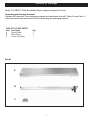
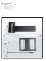
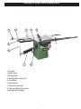
1
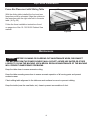
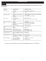
10” Cabinet Saw Sliding Table
Owner’s Manual
Model: 10-110B/E
Record the serial number and date of purchase
in your manual for future reference.
Serial number:
Date of purchase:
For more information:
www.rikontools.com or [email protected]
Part #10-110B/EM2
For Parts or Questions:
[email protected] or 877-884-5167
Operator Safety: Required Reading
IMPORTANT! Safety is the single most important consideration in the operation of this equipment. The following instructions must be followed at all times.
There are certain applications for which this tool was designed. We strongly recommend that this tool not be modified and/or
used for any other application other than that for which it was designed. If you have any questions about its application, do not
use the tool until you have contacted us and we have advised you.
General Safety Warnings
KNOW YOUR POWER TOOL. Read the owner’s manual carefully. Learn the tool’s applications, work capabilities, and its
specific potential hazards.
ALWAYS GROUND ALL TOOLS.
If your tool is equipped with a three-pronged plug, you must plug it into a three-hole electric receptacle.
If you use an adapter to accommodate a two-pronged receptacle, you must attach the adapter plug to a
known ground. Never remove the third prong of the plug.
ALWAYS AVOID DANGEROUS ENVIRONMENTS.
Never use power tools in damp or wet locations. Keep your work area well lighted and clear of clutter.
ALWAYS REMOVE THE ADJUSTING KEYS AND WRENCHES FROM TOOLS AFTER USE.
Form the habit of checking to see that keys and adjusting wrenches are removed from the tool before
turning it on.
ALWAYS KEEP YOUR WORK AREA CLEAN. Cluttered areas and benches invite accidents.
ALWAYS KEEP VISITORS AWAY FROM RUNNING MACHINES.
All visitors should be kept a safe distance from the work area.
ALWAYS MAKE THE WORKSHOP CHILDPROOF.
Childproof with padlocks, master switches, or by removing starter keys.
NEVER OPERATE A TOOL WHILE UNDER THE INFLUENCE OF DRUGS, MEDICATION, OR ALCOHOL.
ALWAYS WEAR PROPER APPAREL.
Never wear loose clothing or jewelry that might get caught in moving parts. Rubber-soled footwear is
recommended for the best footing.
ALWAYS USE SAFETY GLASSES AND WEAR HEARING PROTECTION.
Also use a face or dust mask if the cutting operation is dusty.
NEVER OVERREACH.
Keep your proper footing and balance at all times.
NEVER STAND ON TOOLS.
Serious injury could occur if the tool is tipped or if the cutting tool is accidentally contacted.
2
ALWAYS DISCONNECT TOOLS.
Disconnect tools before servicing and when changing accessories such as blades, bits, and cutters.
ALWAYS AVOID ACCIDENTAL STARTING.
Make sure switch is in “OFF” position before plugging in cord.
NEVER LEAVE TOOLS RUNNING UNATTENDED.
ALWAYS CHECK FOR DAMAGED PARTS.
Before initial or continual use of the tool, a guard or other part that is damaged should be checked to assure
that it will operate properly and perform its intended function. Check for alignment of moving parts, binding
of moving parts, breakage of parts, mounting, and any other conditions that may affect its operation. A guard
or other damaged parts should immediately be properly repaired or replaced.
Table Saw Safety Rules
1. Always wear eye protection.
2. Keep hands away from the saw blade while machine is running.
3. Always use blade guard during normal cutting operations.
4. Always use splitter during normal cutting operations.
5. Use push sticks when ripping narrow stock.
6. Always use fence while ripping and miter gauge while cross-cutting.
7. Never reach over or behind saw blade while machine is running.
8. Do not remove cut-off or jammed pieces until blade has come to a full stop.
9. Disconnect machine from power source before making repairs or adjustments.
10. Do not expose saw or power cord to water or use in damp locations.
SAVE THESE INSTRUCTIONS.
Refer to them often.
3
Table of Contents
Safety Warnings........................................................................................................................................2 -3
Table Saw Safety Rules ..........................................................................................................................3
Specifications ........................................................................................................................................4
Contents of Package ............................................................................................................................5
Unpacking and Checking Contents ...................................................................................................5-6
Getting To Know Your Sliding Table ............................................................................................................7
Assembly ..............................................................................................................................................8-12
Adjustment...................................................................................................................................12-13
Operation.......................................................................................................................13-14
Rip Fence Installation................................................................................................................................. ..... 15
Maintenance .......................................................................................................................................... ..... 15
Troubleshooting........................................................................................................................................16
Parts Diagram...........................................................................................................................17
Parts List................................................................................................................18
Warranty ...................................................................................................................................19
Specifications
Minimum Table Travel
12”
Maximum Table Travel
49”
Sliding Table Dimension
51-12” x 9-7/8”
Miter Fence Length
49-1/4”
Miter Fence Angles
0-45o Forward/Back
18-1/4” x 23-3/4”
Sliding Carriage Size
4
Content of Package
Model 10-110B/E 10” Table Saw Sliding Table is shipped complete in 2 boxes.
Unpacking and Checking Contents
Separate all “loose parts” from packaging materials and check each item with “Table of Loose Parts” to
make sure all items are accounted for, before discarding any packaging material.
TABLE OF LOOSE PARTS
Item Part Name
A
Sliding Table
B
Miter Fence
C
Loose Parts Bag
Qty
1
1
1
Box #1
A
B
C
5
TABLE OF LOOSE PARTS
Item Part Name
A
Swing Arm Assembly
B
Swing Arm Extension Bar
C
Sliding Table Carriage
D
Sliding Table Support Arm
E
Loose Parts Bag
Qty
1
1
1
1
1
Box #2
A
B
E
C
D
6
Getting To Know Your Sliding Table
1
3
2
4
5
9
8
7
6
1. Flip Stop
2. Miter Fence
3. Sliding Table
4. Sliding Table Locking Pin
5. Push Block
6. Slide Handle
7. Swing Arm Assembly
8. Carriage Table Support Arm
9. Sliding Table Carriage
7
Assembly
Mounting the Swing Arm Bracket
1. Open the motor cover located at the left side of
the saw.
2. With assistance hold the swing arm bracket
against the saw body and attach using four 8MM
hex bolts, four 8MM washers and four 8MM hex
nuts.
3. Slide the four 8MM hex bolts through the bracket
and saw body and attach using the four 8 washers
and four 8MM hex nuts from inside the saw body.
Figure 1.
Figure 1
Installing the Swing Arm Extension Bar
1. Slide the swing arm extenstion bar through the
swing arm bracket making sure that the large hole
is installed first and that the set screw is pointing
downward. Figure 2.
Mounting the Sliding Table
Figure 2
1. Locate the sliding table mounting hardware
which includes two knobs, two T-nuts, two 8MM
washers and two adjusting plates. Figure 3.
2. Assemble the hardware as shown (Fig. 3) and
slide the T-nut into the track (Fig. 4) making sure
that the clamp plate is against the bottom of the
table assembly.
Figure 3
Figure 4
8
Assembly
Mounting the Sliding Table Continued
A
3. Slide the hardware toward the cast mounting
bracket located on the saw body. Place the
adjusting plate on top of the set screws as shown
(A,Fig.5).
4. Tighten the lock knob slightly, leaving loose for
adjustment.
5. Repeat procedure for rear mounting bracket.
Figure 5
6. Adjusting the parallel of the saw table and sliding
table with the four set screws (A, Fig.5).
Installing the Sliding Table Carriage
1. Locate the sliding table carriage mounting
hardware as shown. Figure 6.
Figure 6
2. Slide the T-nuts bar into the side channel of the
sliding table. Figure 7.
Figure 7
3. Attach the carriage table support arm to the
bottom the the sliding table carriage using two 8MM
carriage bolts, two 8MM washers and two 8MM hex
bolts. The head of the carriage bolts should lock
into the bottom of the sliding table carriage. Finger
tighten the two 6MM hex bolts only until next step
is completed. Figure 8.
Figure 8
9
Assembly
Carriage Table Support Arm Installation
A
1. Insert the support arm into the swing arm
extension bar as shown (A, Fig. 9) making sure
that bearing assembly rests between the adjusting
nuts and the swing arm extension bar (B, Fig. 9).
B
Reminder: Tighten the carriage bolts shown in
Figure 8 on page nine once the support arm is
installed.
Figure 9
2. Hold the support arm in place by installing the
second bearing set and adjusting nuts as shown.
The second set of bearings should be installed
against the bottom side of swing arm extension
bar. Figure 10.
NOTE: Do not overtighten the adjusting nuts as
the bearings will bind and the table will not slide
smoothly.
Figure 10
3. Hold the sliding table carriage against the
sliding table and install the lock knobs through
the carriage to the T-nuts bar in the sliding table
channel. Figure 11.
Figure 11
4. Line up the two holes in the side of the support
arm with the two holes in the side of the sliding
table carriage (Fig. 12).
5. Insert the two locking knobs with the long
threaded ends as well as two 6MM washers
through the support arm and through the sliding
table carriage (Fig. 12). Attach with with two 6MM
washers and two 6MM hex nuts.
Figure 12
10
Assembly
Installing the Sliding Table Miter Fence
1. Locate the miter fence (A, Fig. 13) and miter
fence locking knob (B, Fig. 13) as shown.
B
A
Figure 13
2. Lay the miter fence on top of the sliding table
carriage and place the rotation shaft into the hole
on the sliding table carriage. Figure 14.
Figure 14
3. Install the miter fence locking knob from the
underneath of the sliding table carriage. Figure 15.
Figure 15
11
Assembly
Installing the Sliding Table Locking Pin
A
1. Locate the locking pin with the black handle and
thread it through the sliding table body with wrench
as shown. Figure 17.
Figure 17
Adjustment
Leveling the Sliding Table to the Saw
NOTE:
The sliding table should be set approximately 3/64”
of an inch higher than the saw table to prevent
sheet goods from binding against the table.
A
1. Loosen the two sliding table lock knobs slightly.
(B, Fig. 18)
2. Adjust the set screws acordingly which will place
pressure against the pressure plate (A, Fig. 18)
3. Tighten the sliding table lock knobs and check
adjustment. Repeat if necessary.
B
Figure 18
Leveling the Sliding Table Carriage
B
1. Loosen the lower adjusting nuts on the carriage
table support arm (A, Fig. 19).
2. Raise or lower the upper adjusting nuts until the
sliding table carriage is level (B, Fig. 19).
3. Tighten the lower adjusting nuts and check table
for level. Repeat if necessary.
A
Checking Sliding Table Parallel to Saw
Table
Figure 19
After the adjustments above are completed it may
be necessary to check for parallel, especially if the
sliding table scrubs the saw table.
To align for parallel please repeat the steps
described above. If further adjustment is needed,
loosen the 8MM hex head bolts that hold the cast
mounting bracket to the body of the saw. (A,Fig 20)
A
12
Figure 20
Adjustment
Slide Table Clearance to Saw Blade
1. Place a square on the front edge of the sliding
table. (A-Fig. 20)
B
A
2. Push the sliding table until the top of the square
clears the back edge of the leading tooth on the
saw blade. (B-Fig. 20)
Figure 20
3. If the square does not clear the back edge of
the leading tooth on the saw blade, loosen the two
locking knobs under the slide table. Move the table
support forward or backwards until the aligment is
correct. (A-Fig. 21)
Locking knob
Figure 21
Operation
Locking and Unlocking the Slide Table
WARNING!
Keep the sliding table locked when
not in use. Failure to do so could cause serious
injury.
To lock the sliding table, pull the locking pin outward, twist and insert pin into the locking hole in
the table carriage. (Fig. 22)
To unlock the sliding table, pull the locking pin outward, twist and rest the cross pin into the seat of
the lock knob body. (Fig. 22)
Figure 22
13
Operation
Cutting Sheet Goods
1. Adjust the hold down plate according to the
width of material to be cut.
2. Lay the workpiece onto the table and up against
the saw fence.
3. Slide the workpiece through the saw blade until
the material engages the hold down plate. Walk
the workpiece through the cut with the sliding table
until the workpiece clears the saw blade and the
cut is completed.
Figure 23
Cross Cutting
For cross cutting panels and narrow stock, position
the miter fence onto the sliding table carriage as
shown. Tighten lock knobs. (Fig. 24)
Making sure that table lock is disengaged, postion
the workpiece against the miter fence and push
sliding table through the cut.
Figure 24
Miter Cuts
Loosen the lock knob on the right side of the
miter fence (closest to blade) slightly and use as a
pivot point. Loosen the lock knob on the left side of
the miter fence and position the miter fence to the
desired angle using the scale on the sliding table
carriage. (Fig. 25)
Figure 25
14
Rip Fence Installation
Fence Bar Placement with Sliding Table
With the sliding table installed the front and rear
fence bars must be relocated. Align the notches in
the fence bars with the right miter slot in the main
table. (A-Fig. 26)
Follow the fence installation instructions found
on page nine of the 10-110/10-050 Cabinet Saw
manual.
A
Figure 26
Maintenance
Caution! BEFORE CLEANING OR CARRYING OUT MAINTENANCE WORK, DISCONNECT
THE MACHINE FROM THE POWER SOURCE (WALL SOCKET). NEVER USE WATER OR OTHER
LIQUIDS TO CLEAN THE MACHINE. USE A BRUSH. REGULAR MAINTENANCE OF THE MACHINE
WILL PREVENT UNNECESSARY PROBLEMS.
Keep the table clean to ensure accurate cutting.
Keep the table mounting area clean to ensure accurate operation of all moving parts and prevent
excessive wear.
Check sliding table alignment to the table saw work surface to correct or prevent rubbing.
Keep the inside (near the saw blade, etc.) clean to prevent accumulation of dust.
15
Troubleshooting
WARNING!
FOR YOUR OWN SAFETY, ALWAYS TURN OFF AND UNPLUG THE MACHINE BEFORE CARRYING OUT ANY TROUBLESHOOTING.
For parts or technical questions contact: [email protected] or 877-884-5167.
16
Parts Diagram
17
Parts List
Key
No.
1E
2E
3E
4E
5E
6E
7E
8E
9E
10E
11E
12E
13E
14E
15E
16E
17E
18E
19E
20E
21E
22E
23E
24E
25E
26E
27E
28E
29E
30E
1F
2F
3F
4F
5F
6F
7F
8F
9F
10F
11F
12F
Part No.
Description
Key
No.
1-JL82236009
Support arm
13F
1-JL82212006
End cap
14F
1-M20GB6173
Hex nut M20
15F
1-BRG51104GB301
Thrust bearing
16F
1-JL84070002
Extension arm
1G
1-JL82236002
End cap
2G
1-M4X8GB818Z
Hex bolt M4x8
3G
1-WSH5GB96Z
Washer 5
4G
1-JL82236003
Swing arm assembly 5G
1-JL84070001
Seat - Swing arm
6G
1-M8GB6170Z
Hex nut M8
7G
1-WSH8GB96Z
Washer 8
8G
1-M8X25GB5783Z
Hex bolt M8x25
9G
1-M8X20GB801Z
Hex bolt M8x20
10G
1-M10X25GB5781B Hex bolt M10x25
11G
1-WSH10GB95B
Washer 10
12G
1-BRG6202GB276
Bearing 6202-Z
13G
1-JL82236005
Shaft
14G
1-CLP15GB894D1B Retaining ring
1H
1-JL82236011
Adjustable seat
2H
1-M6X30GB5781Z
Hex bolt M6x30
3H
1-M6GB6170Z
Hex nut M6
4H
1-WSH16GB95Z
Washer 16
5H
1-M16GB6170Z
Hex nut M16
6H
1-M8X60GB5781Z
Hex bolt M8X60
7H
1-M6X10GB70Z
Bolt M6x10
8H
1-WSH6GB95Z
Washer 6
9H
1-JL82236006
Shaft
10H
1-JL82236007
Eccentric shaft
11H
1-JL82236008
Roller
12H
1-JL82213003
Miter fence
13H
1-ST3D5X9D5GB845Z Panhead screw
14H
1-WSH6GB5287Z
Washer 6
15H
1-JL82030006
Square nut
16H
1-PIN6X45GB119
Pin
17H
1-M6X10GB77B
Set screw M6X10
18H
1-WSH6GB95Z
Washer 6
19H
1-M6X10GB70Z
Hex screw M6X10 20H
1-JL82213015
Guide plate
21H
1-JL82213006
Small shaft
22H
1-JL82213007
End cap
1-JL82213008
Scale I
18
Part No.
Description
1-JL82213009-001Y
1-JL82213010
1-JL82213011-001Y
1-JL82213018
1-JL82213016
1-M6GB6170Z
1-WSH6GB96Z
1-JL84100003
1-JL84102000
1-JL84102000A
1-JL84100002
1-JL84101000
1-JL84100001
1-JL82233007
1-WSH8GB95Z
1-M8GB6170Z
1-RVT3X7GB12618A
1-M8X40GB77B
1-JL84061000
1-M10GB39Z
1-JL26060012
1-M10GB6170Z
1-JL82240007
1-WSH8GB95Z
1-JL82240011
1-JL82233007
1-JL82243000
1-JL82240010
1-M6X12GB77B
1-JL84060001
1-JL84060002
1-M8X20GB5781Z
1-M8GB6177D1Z
1-WSH8GB96Z
1-JL84060003
1-JL20061101
1-JL20061102
1-M6X16GB5781Z
1-WSH6GB96Z
1-JL82030006
Flip stop
Magnifier
Sliding block
Thumb screw II
Thumb screw I
Hex nut M6
Washer 6
Clamp block
Clamp handle assembly I
Clamp handle assembly II
Clamp plate
Sliding table frame assembly
Angle scale
Position pin
Washer 8
Hex nut M8
Rivet
Set screw M8X40
Sliding carriage
Square nut
Handle
Hex nut M10
Square nut
Washer 8
Thumb Screw
Set screw
Position handle
Plate
Set screw M6x12
Support plate, front
Support plate, back
Hex bolt M8x20
Flange nut
Washer 8
Clamp plate
Knob cover
Knob body
Bolt M6x16
Washer 6
Square nut
Warranty
2-Year Limited Warranty
RIKON Power Tools/Richen Enterprise, Inc. (“Seller”) warrants to only the original retail
consumer/purchaser of our products that each product be free from defects in materials and
workmanship for a period of two (2) years from the date the product was purchased at retail. This
warranty may not be transferred.
This warranty does not apply to defects due directly or indirectly to misuse, abuse, negligence,
accidents, repairs, alterations, lack of maintenance or normal wear and tear. Under no
circumstances will Seller be liable for incidental or consequential damages resulting from
defective products. All other warranties, expressed or implied, whether of merchantability,
fitness for purpose, or otherwise are expressly disclaimed by Seller. This warranty does not cover
products used for commercial, industrial or educational purposes.
This limited warranty does not apply to accessory items such as blades, drill bits, sanding discs or
belts and other related items.
Seller shall in no event be liable for death, injuries to persons or property, or for incidental,
contingent, special, or consequential damages arising from the use of our products.
To take advantage of this warranty proof of purchase documentation, which includes date of
purchase and an explanation of the complaint, must be provided.
The Seller reserves the right to effect at any time, without prior notice, those alterations to parts,
fittings, and accessory equipment which they may deem necessary for any reason whatsoever.
To take advantage of this warranty, please fill out the enclosed warranty card and send it to:
RIKON Warranty
110 Cummings Park
Woburn, MA 01801
The card must be entirely completed in order for it to be valid. If you have any questions
please contact us at 877-884-5167 or [email protected].
19
For more information:
110 Cummings Park
Woburn, MA 01801
877-884-5167/781-933-8400
[email protected]
www.rikontools.com
Copyright Richen Enterprise, Inc. 2007
Printed in China 6/07