1
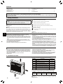
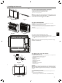
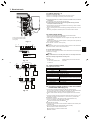
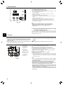
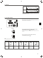
Air-Conditioners For Building Application
INDOOR UNIT
PFFY- P • VKM-E (2)
INSTALLATION MANUAL
FOR INSTALLER
For safe and correct use, read this manual and the outdoor unit installation manual thoroughly before installing
the air-conditioner unit.
INSTALLATIONSHANDBUCH
FÜR INSTALLATEURE
Aus Sicherheitsgründen und zur richtigen Anwendung vor Installation der Klimaanlage die vorliegende Bedienungsanleitung und das Installationshandbuch gründlich durchlesen.
MANUEL D’INSTALLATION
Português (P)
MONTÖR İÇİN
Emniyetli ve doğru kullanım için, klima cihazını monte etmeden önce bu kılavuzu ve dış ünite montaj kılavuzunu
tamamıyla okuyun.
РУКОВОДСТВО ПО УСТАНОВКЕ
Ελληνικά (GR)
PARA O INSTALADOR
Para uma utilização segura e correcta, leia atentamente este manual e o manual de instalação da unidade exterior antes de instalar o aparelho de ar condicionado.
MONTAJ ELKİTABI
Italiano (I)
ΓΙΑ ΑΥΤΟΝ ΠΟΥ ΚΑΝΕΙ ΤΗΝ ΕΓΚΑΤΑΣΤΑΣΗ
Για σωστή και ασφαλή χρήση, διαβάστε προσεκτικά αυτό το εγχειρίδιο, καθώς και το εγχειρίδιο εγκατάστασης
της εξωτερικής μονάδας, πριν από την εγκατάσταση της μονάδας κλιματιστικού.
MANUAL DE INSTALAÇÃO
Español (E)
PER L’INSTALLATORE
Per un uso sicuro e corretto, prima di installare il condizionatore d’aria leggere attentamente il presente manuale
ed il manuale d’installazione dell’unità esterna.
ΕΓΧΕΙΡΙΔΙΟ ΟΔΗΓΙΩΝ ΕΓΚΑΤΑΣΤΑΣΗΣ
Nederlands (NL)
PARA EL INSTALADOR
Para un uso seguro y correcto, lea detalladamente este manual de instalación antes de montar la unidad de
aire acondicionado.
MANUALE DI INSTALLAZIONE
Français (F)
VOOR DE INSTALLATEUR
Lees deze handleiding en de installatiehandleiding van het buitenapparaat zorgvuldig door voordat u met het
installeren van de airconditioner begint.
MANUAL DE INSTALACIÓN
Deutsch (D)
POUR L’INSTALLATEUR
Avant d’installer le climatiseur, lire attentivement ce manuel, ainsi que le manuel d’installation de l’appareil extérieur pour une utilisation sûre et correct.
INSTALLATIEHANDLEIDING
English (GB)
ДЛЯ УСТАНОВИТЕЛЯ
Для обеспечения безопасной и надлежащей эксплуатации внимательно прочтите данное руководство и
руководство по установке наружного прибора перед установкой кондиционера.
Türkçe (TR)
Русский (RU)
Contents
1. Safety precautions ........................................................................................ 2
2. Installation location ....................................................................................... 2
3. Installing the indoor unit................................................................................ 3
4. Refrigerant pipe ........................................................................................... 4
5. Drainage piping work .................................................................................... 5
6. Embedding the indoor unit in a wall.............................................................. 6
7. Electrical work .............................................................................................. 7
8. Test run ......................................................................................................... 8
9. Air outlet selection ........................................................................................ 9
Note:
The phrase “Wired remote controller” in this installation manual refers only to the PAR-21MAA.
If you need any information for the other remote controller, please refer to either the installation manual or initial setting manual which
are included in these boxes.
1. Safety precautions
: Indicates an action that must be avoided.
► Before installing the unit, make sure you read all the “Safety precautions”.
► Please report to your supply authority or obtain their consent before
connecting this equipment to the power supply system.
: Indicates a part which must be grounded.
Warning:
Describes precautions that must be observed to prevent danger of injury or
death to the user.
: Indicates that caution should be taken with rotating parts.
Caution:
Describes precautions that must be observed to prevent damage to the unit.
: Beware of electric shock.
After installation work has been completed, explain the “Safety Precautions,” use,
and maintenance of the unit to the customer according to the information in the
Operation Manual and perform the test run to ensure normal operation. Both the
Installation Manual and Operation Manual must be given to the user for keeping.
These manuals must be passed on to subsequent users.
Warning:
• Ask the dealer or an authorized technician to install the air conditioner.
• Install the unit at a place that can withstand its weight.
• Use only specified cables for wiring. The wiring connections must be
made securely with no tension applied on the terminal connections. Also,
never splice the cables for wiring (unless otherwise indicated in this document).
Failure to observe these instructions may result in overheating or a fire.
• Use only accessories authorized by Mitsubishi Electric and ask the dealer
or an authorized technician to install them.
• Do not touch the heat exchanger fins.
• Install the air conditioner according to this Installation Manual.
Caution:
• Do not use the existing refrigerant piping, when use R410A or R407C refrigerant.
• Use ester oil, either oil or alkylbenzene (small amount) as the refrigerator oil
to coat flares and flange connections, when use R410A or R407C refrigerant.
• Do not use the air conditioner where food, pets, plants, precision instruments, or artwork are kept.
• Do not use the air conditioner in special environments.
• Ground the unit.
: Indicates that the main switch must be turned off before servicing.
: Beware of hot surface.
ELV
: At servicing, please shut down the power supply for both the Indoor and
Outdoor Unit.
Warning:
Carefully read the labels affixed to the main unit.
• Have all electric work done by a licensed electrician according to local
regulations.
• If the air conditioner is installed in a small room, measures must be taken
to prevent the refrigerant concentration from exceeding the safety limit
even if the refrigerant should leak.
• The cut face punched parts may cause injury by cut, etc. The installers are
requested to wear protective equipment such as gloves, etc.
• When installing or relocating, or servicing the outdoor unit, use only the
specified refrigerant (R410A) to charge the refrigerant lines. Do not mix it
with any other refrigerant and do not allow air to remain in the lines.
If air is mixed with the refrigerant, then it can be the cause of abnormal high
pressure in the refrigerant line, and may result in an explosion and other
hazards.
The use of any refrigerant other than that specified for the system will cause
mechanical failure or system malfunction or unit breakdown. In the worst
case, this could lead to a serious impediment to securing product safety.
•
•
•
•
•
•
•
Install an leak circuit breaker, as required.
Use power line cables of sufficient current carrying capacity and rating.
Use only a circuit breaker and fuse of the specified capacity.
Do not touch the switches with wet fingers.
Do not touch the refrigerant pipes during and immediately after operation.
Do not operate the air conditioner with the panels and guards removed.
Do not turn off the power immediately after stopping operation.
2. Installation location
(mm)
The indoor unit should be supplied with the following accessories.
PART NUMBER
0
20
700
A
1
2
3
4
5
6
7
8
9
B
600
GB
: Indicates that important instructions must be followed.
ACCESSORY
QUANTITY
Drain hose
1
Pipe cover
1
Band
2
Indoor unit mounting bracket
1
Fixing screw for 4 4 × 25 mm
5
Wood screw for the indoor unit fixation
4
Washer of 6
4
Felt tape (Used for left or left-rear piping)
1
MA Remote controller cable
1
2.1. Outline dimensions (Indoor unit) (Fig. 2-1)
C
The unit must be securely installed on a structure that can sustain its weight.
Models
P20/25/32/40
D
2
Fig. 2-1
A
100 mm or more
B
100 mm or more
C
100 mm or more
D
150 mm or below
from the floor
Warning:
Mount the indoor unit on a wall structure strong enough to withstand the
weight of the unit.
3. Installing the indoor unit
(mm)
131
0
20
3.1. Indoor unit mounting bracket installation
14
(700
)
• Install the bracket firmly to the wall structure (stud, etc.). (Fig. 3-1)
• Use a level to install the mounting bracket horizontally.
• Install the indoor unit 150 mm or below from the floor.
A Indoor unit mounting bracket
586
(600)
131
Note:
To prevent the indoor unit mounting bracket from vibrating slightly, be sure
to fasten the bracket at the holes indicated by . In addition, fasten the
bracket at the holes indicated by if possible. (Fig. 3-2)
Fig. 3-1
Fig. 3-2
3.2. Indoor unit preparation
1 Press the 2 positions indicated by the arrows
and open the front grille.
(Fig. 3-3)
2 Open the front grille and remove the 2 screws.
3 Open the horizontal vane for the upper air outlet, push the top of the front panel
in 3 locations, and then pull the top of the grille away from the indoor unit.
B Screws
4 Lift up the front grille to remove it. (Fig. 3-4)
GB
Fig. 3-4
Fig. 3-3
674
3.3. Indoor unit installation (Fig. 3-5)
• Hook the top of the indoor unit on the indoor unit mounting bracket.
• Use the included wood screws and washer, and fasten the indoor unit at 2 locations ( ) each at the top and the middle of the unit.
210
333
363
Note:
Install the indoor unit securely to the wall, making sure that there is no gap
between the unit and the wall.
Fig. 3-5
3.4. Making holes in the wall and floor
3.4.1. Making holes (Fig. 3-6)
1 Make ø65 mm or ø75 mm holes that are approximately 5–7 mm deep and angled slightly downward outward from the room.
2 Insert the wall hole sleeves into the holes.
A Wall hole
B 65 mm or 75 mm dia.
C Indoor side
D Wall hole cross section
E Wall thickness
F One scale
G Cut with 1 extra scale length.
H Wall hole sleeve
Fig. 3-6
700
1)
131
131
Caution:
Be sure to use the wall hole sleeves. Otherwise, the indoor/outdoor unit connecting wires may contact a metal object in the wall or, in the case of hollow
walls, small rodents may gnaw on the wires, resulting in a very dangerous
situation.
599
Fig. 3-7
78
97
80
600
496
14
288
3.4.2. Determining hole positions
The areas where the piping can be routed are indicated with oblique lines in the
figure.
1) For rear or left-rear piping (Fig. 3-7)
(The following figure is a front view of the indoor unit installation location.)
23
3
3. Installing the indoor unit
(mm)
200
150
2) For right downward or left downward piping (Fig. 3-8)
(The following figure is a view of the bottom of the indoor unit from above.)
A When the unit is installed on the wall.
B When the unit is installed on the floor.
75
168
147
31
73
60
61
105
2)
62
700
Fig. 3-8
4)
3)
3) For left piping (Fig. 3-9)
4) For right piping (Fig. 3-10)
3.4.3. Sealing the holes
60
19
19 60
Use putty or a caulking compound to seal the holes.
60
60
Fig. 3-9
Fig. 3-10
GB
4. Refrigerant pipe
B
4.1. Connecting pipes (Fig. 4-1)
• When commercially available copper pipes are used, wrap liquid and gas pipes
with commercially available insulation materials (heat-resistant to 100°C or more,
thickness of 12 mm or more).
• The indoor parts of the drain pipe should be wrapped with polyethylene foam
insulation materials (specific gravity of 0.03, thickness of 9 mm or more).
• Apply thin layer of refrigerant oil to pipe and joint seating surface before tightening flare nut.
• Use two wrenches to tighten piping connections.
• Use refrigerant piping insulation provided to insulate indoor unit connections.
Insulate carefully.
Warning:
When installing the unit, securely connect the refrigerant pipes before starting the compressor.
øA
45°±2°
.4
R0
90° ±0.5°
A
.8
R0
C
A Flare cutting dimensions
D
Fig. 4-1
B Refrigerant pipe sizes & Flare nut tightening torque
P20/25/32/40
R407C or R22
Liquid pipe
Gas pipe
Tightening
Tightening
Pipe size
Pipe size
torque
torque
(mm)
(mm)
(N·m)
(N·m)
O.D. ø6.35 (1/4”)
14 - 18
O.D. ø12.7 (1/2”)
49 - 61
Copper pipe O.D.
Flare dimensions
(mm)
ø6.35
ø9.52
ø12.7
ø15.88
ø19.05
øA dimensions (mm)
8.7 - 9.1
12.8 - 13.2
16.2 - 16.6
19.3 - 19.7
23.6 - 24.0
R410A
Liquid pipe
Gas pipe
Tightening
Tightening
Pipe size
Pipe size
torque
torque
(mm)
(mm)
(N·m)
(N·m)
O.D. ø6.35 (1/4”)
14 - 18
O.D. ø12.7 (1/2”)
49 - 61
Flare nut O.D.
Liquid pipe
(mm)
Gas pipe
(mm)
17
26
C Apply refrigerating machine oil over the entire flare seat surface.
* Do not apply refrigerating machine oil to the screw portions. (This will make the flare nuts more apt to loosen.)
D Be certain to use the flare nuts those are attached to the main unit. (Use of commercially-available products may result in cracking.)
4.2. Refrigerant piping
4.2.1. Connecting pipe installation
Install the connecting pipes so that the piping can move slightly to the front, back,
left, and right. (Fig. 4-2)
4
Fig. 4-2
4. Refrigerant pipe
1)
1) For right downward piping (Fig. 4-3)
2) For piping other than right downward (Fig. 4-4)
A Bands
B Pipe covers
C Remove the cover.
• Be sure to insulate the connecting pipes and place them near the rear of the indoor unit so that they do not contact the front panel.
• Be careful not to crush the connecting pipes when bending them.
2)
Fig. 4-4
3)
3) For left or left-rear piping (Fig. 4-5)
Bundle the connecting pipes and drain hose together, and then wrap them in felt
tape.
A Make sure that the drain hose is not routed upward.
B Felt tape
* Wrap the felt tape tightly around the pipes and hose starting near where the
pipes and hose are routed from the indoor unit. (The overlap width of the felt
tape should not be more than 1/2 of the tape width.)
C Start wrapping the piping tape around the pipes and hose 10 mm inside the
indoor unit.
D Fasten the end of the felt tape with a bandage stopper.
Fig. 4-5
Installing flush against a wall with
molding
Cut and use the lower side panels on the left and right sides of the indoor unit as
shown.
Smooth the cut edges of the side panels so that they will not damage the insulation
coating. (Fig. 4-6)
E Cut the lower side panels to match the height of the modelling.
For left or right piping
Fig. 4-6
5. Drainage piping work
5.1. Drainage piping work
Fig. 5-1
Fig. 5-2
• Be sure to route the drain piping slightly downward (1/100 or more) so that the
drain water flows easily.
• Do not route the drain piping as shown in the examples mark with an “X” in the
figure. (Fig. 5-1)
• If the drain hose is too short, refer to Fig. 5-2 to extend the length of the hose.
• If the indoor unit is installed in a high location such as a high-rise apartment,
strong winds may cause the drain water to flow back through the drain hose and
leak from the unit. If necessary, contact your nearest Mitsubishi Electric representative for the optional parts to prevent this problem.
• If the drain hose is routed indoors, be sure to wrap it in commercially-available
insulation.
• Do not connect the drain piping directly to a septic tank, sewage tank, etc., where
ammonia gases or hydrogen sulfide are produced.
• If there is slack in the drain hose or the end of the drain hose is raised up, the
drain water may not flow smoothly and some drain water may collect in the hose.
This can lead to a strange sound (burbling) being produced during strong winds
or when a ventilation fan, etc., is used in a residence that is well-sealed. If necessary, contact your nearest Mitsubishi Electric representative for the optional parts
to prevent this problem.
A Sloping downward
B No upward slope
C Accumulated drain water
D Air
E End of drain hose is immersed in water.
F Drainage channel
G 50 mm or less from ground
H Drain hose
I Fixable PVC hose (inner diameter: 15 mm) or rigid PVC pipe (VP-15)
• When routing the drain piping, make sure that the drain hose is routed as shown.
(Fig. 5-3)
200
50
Fig. 5-3
5
GB
Fig. 4-3
5. Drainage piping work
• Insert the drain hose all the way to the base of the drain pan. (Fig. 5-4) Make sure
that the drain hose is securely caught on the projection in the hole in the drain
pan.
Fig. 5-4
• Route the drain hose diagonally below the connecting pipes. (Fig. 5-5)
A Piping tape
B Refrigerant piping
C Drain hose
• Make sure that the drain hose is not routed upward and that there are no waves
in the hose.
• Do not pull the drain hose, and then wrap tape around it.
• Route the piping so that it does not project past the rear of the indoor unit. (Refer
to the figure to the left.)
D Piping bent outward
E Push
6. Embedding the indoor unit in a wall
6.1. Embedding the indoor unit in a wall (Fig. 6-1)
475
52
65
GB
Fig. 5-5
Fig. 6-1
• On the indoor unit and right and left space (100 mm or more) are the service
space.
• On a right side of the indoor unit, there is a hole for the room temperature sensor,
and do not close it, please.
• When installing a grating, use a grating with narrow upper and lower horizontal
bars so that the airflow from the upper and lower air outlets does not contact the
bars. If the horizontal bars will block the lower air outlet, use a stand, etc., to adjust the height of the indoor unit. If the upper or lower air outlet is blocked, the air
conditioner will not be able to cool or warm the room well.
• Use a grating with vertical bars, etc., that has at least 75% open area. If the grating has horizontal bars or if the open area is less than 75%, performance could
be reduced.
• When the indoor unit is embedded in a wall (built-in), the time it takes for the room
temperature to reach the set temperature will increase.
A 100 mm or more
B Upper air outlet
C Lower air outlet
D Grating
E 100 mm or more
F Indoor unit
G 35 mm or more
6.2. Embedded indoor unit setting (must be performed)
(Fig. 6-2)
SW3
ON
1 2 3 4 5 6 7 8 9 10
Fig. 6-2
6
• When embedding the indoor unit in a wall, restrict the movement of the horizontal
vane for the upper air outlet so that it only operates horizontally.
• If this setting is not performed, heat will build up in the wall and the room will not
be cooled or warmed properly.
• Remove the electrical part cover and pull out the control board.
• Set DIP switches 3-5 and 3-6 on the control board to ON.
• After setting the switches, reinstall the control board in its original position and
install the electrical part cover.
Caution:
To avoid damage to the control board due to static electricity, be sure to discharge the static buildup before handling it.
7. Electrical work
7.1. Indoor unit (Fig. 7-1)
1 Remove the electrical cover.
• Remove 1 screw holding the electrical cover, then move the cover.
• Remove 1 screw holding the cord clamp, then move the clamp.
2 Connect the power line, control line from the outdoor unit, and remote
control lines.
After connecting, secure the wires with the cord clamp.
► Fix power source wiring to control box using buffer bushing for tensile
force. (PG connection or the like.)
• Since the electric box may need to be pulled out for servicing or other occasions,
wires must have enough slack.
• Class 3 grounding work must be conducted (grounding wire diameter: 1.6 mm or
more)
After wiring is completed, reinstall the parts in the reverse order of removal.
7.2. Power supply wiring
• Wiring size must comply with the applicable local and national codes.
• Install an earth line longer than other cables.
• Power supply codes of appliance shall not be lighter than design 60245 IEC 53
or 60227 IEC 53.
• A switch with at least 3 mm contact separation in each pole shall be provided by
the air conditioner installation.
Power cable size : more than 1.5mm² (3-core)
Power supply terminal block (TB2)
Transmission terminal block (TB5)
Wiring clamp
Fig. 7-1
Warning:
Never splice the power cable or the indoor-outdoor connection cable, otherwise it
may result in a smoke, a fire or communication failure.
► Use earth leakage breaker (NV).
For breaker, means shall be provided to ensure disconnection of all active phase
conductors of the supply.
L N
TB2
Warning:
Wiring should be done so that the power lines are not subject to tension.
Otherwise, heat may be generated or fire may occur.
M1 M2 S
TB5
[Fig. 7-2]
A Switch 16 A
B Overcurrent protection 16 A
C Indoor unit
Fig. 7-2
Indoor controller board
M1 M2
M1 M2 S
TB3
D Total operating current be less than 16 A
E Pull box
CN3A
T B5
M1 M2 S
1 2
TB 5
T B15
7.3. Types of control cables
1. Wiring transmission cables
Types of transmission cable
Cable diameter
Length
/
Shielding wire CVVS or CPEVS
More than 1.25 mm²
Less than 200m
2. M-NET Remote control cables
M1 M2
TB3
M1 M2 S
M1 M2 S
TB5
TB5
Types of remote control cable Shielding wire MVVS
Cable diameter
0.5 to 1.25 mm²
Add any portion in excess of 10m to within the
Length
longest allowable transmission cable length 200m
3. MA Remote control cables
Types of remote control cable 2-core cable (unshielded)
Cable diameter
0.3 to 1.25 mm²
Length
Less than 200m
Fig. 7-3
7.4. Connecting remote controller, indoor and outdoor
transmission cables (Fig. 7-3)
• Connect indoor unit TB5 and outdoor unit TB3. (Non-polarized 2-wire)
The “S” on indoor unit TB5 is a shielding wire connection. For specifications about
the connecting cables, refer to the outdoor unit installation manual.
• Install a remote controller following the manual supplied with the remote controller.
• Connect the remote controller’s transmission cable within 10 m using a 0.75 mm2
core cable. If the distance is more than 10 m, use a 1.25 mm2 junction cable.
1 MA Remote controller
• Connect the connector for MA remote controller. (Non-polarized 2-wire)
• DC 9 to 13 V between 1 and 2 (MA remote controller)
a MA remote controller cable (ACCESSORY 9)
2 M-NET Remote controller
• Connect the “M1” and “M2” on indoor unit TB5 to a M-NET remote controller. (Non
-polarized 2-wire)
• DC 24 to 30 V between M1 and M2 (M-NET remote controller)
A Terminal block for indoor transmission cable
B Terminal block for outdoor transmission cable
C Remote controller
7
GB
7. Electrical work
7.5. Setting addresses (Fig. 7-4)
SW5
220V
240V
CN43
SW1
ON
OFF
CN82
1 2 3 4 5 6 7 8 9 10
SW11
9
D
7 8
7 8
SW14
E
F0 1 2
3456
2 3
2 3
4
5 6
5 6
(10ths DIGIT)
SWC
0 1
BC
0 1
4
9
789A
SW12
./
.
(BRANCH No.)
(1s DIGIT)
Fig. 7-4
(Be sure to operate with the main power turned OFF.)
• There are 2 types of rotary switch setting available: setting addresses 1 to 9 and
over 10, and setting branch numbers.
1 How to set addresses
Example: If Address is “3”, remain SW12 (for over 10) at “0”, and match
SW11 (for 1 to 9) with “3”.
2 How to set branch numbers SW14 (Series R2 only)
Match the indoor unit’s refrigerant pipe with the BC controller’s end connection
number.
Remain other than series R2 at “0”.
• The rotary switches are all set to “0” when shipped from the factory. These
switches can be used to set unit addresses and branch numbers at will.
• The determination of indoor unit addresses varies with the system at site. Set
them referring to the Data Book.
Note:
Please set the switch SW5 according to the power supply voltage.
• Set SW5 to 240 V side when the power supply is 230 and 240 volts.
• When the power supply is 220 volts, set SW5 to 220 V side.
A Address board
GB
7.6. Sensing room temperature with the built-in sensor
in a remote controller (Fig.7-4)
If you want to sense room temperature with the built-in sensor in a remote
controller, set SW1-1 on the control board to “ON”. The setting of SW1-7 and
SW1-8 as necessary also makes it possible to adjust the air flow at a time when
the heating thermometer is OFF.
8. Test run
8.1. Before test run
► After completing installation and the wiring and piping of the indoor and
outdoor units, check for refrigerant leakage, looseness in the power
supply or control wiring, wrong polarity, and no disconnection of one
phase in the supply.
► Use a 500-volt megohmmeter to check that the resistance between the
power supply terminals and ground is at least 1.0 M".
TEST RUN
COOL, HEAT
˚C
˚C
SIMPLE
TEMP.
MENU
BACK
MONITOR/SET
PAR-21MAA
ON/OFF
ON/OFF
FILTER
DAY
CLOCK
CHECK TEST
OPERATION
CLEAR
ON/OFF button
Test run display
Indoor liquid pipe
temperature display
ON/OFF lamp
Power display
Error code display
Test run remaining time
display
Set temperature button
Mode selection button
Fan speed button
Air direction button
TEST button
Fig. 8-1
8
► Do not carry out this test on the control wiring (low voltage circuit)
terminals.
Warning:
Do not use the air conditioner if the insulation resistance is less than 1.0 M".
8.2. Test run (Using wired remote controller) (Fig 8-1)
1 Turn on the power at least 12 hours before the test run.
2 Press the [TEST] button twice. “TEST RUN” liquid crystal display
3 Press the [Mode selection] button. Make sure that wind is blown out.
4 Press the [Mode selection] button and switch to the cooling (or heating) mode.
Make sure that cold (or warm) wind is blown out.
5 Press the [Fan speed] button. Make sure that the wind speed is switched.
6 Check operation of the outdoor unit fan.
7 Release test run by pressing the [ON/OFF] button. Stop
8 Register a telephone number.
The telephone number of the repair shop, sales office, etc., to contact if an error
occurs can be registered in the remote controller. The telephone number will be
displayed when an error occurs. For registration procedures, refer to the operation
manual for the indoor unit.
Note:
• If an error code is displayed on the remote controller or if the air conditioner
does not operate properly, refer to the outdoor unit installation manual or
other technical materials.
• The OFF timer is set for the test run to automatically stop after 2 hours.
• During the test run, the time remaining is shown in the time display.
• During the test run, the temperature of the indoor unit refrigerant pipes is
shown in the room temperature display of the remote controller.
• When the VANE or LOUVER button is pressed, the message “NOT
AVAILABLE” may appear on the remote controller display depending on the
indoor unit model, but this is not a malfunction.
• For the PFFY-P•VKM series, the airflow direction displayed on the remote
controller is different from the actual airflow direction. Refer to the
following table.
8. Test run
1
(Horiz.)
2
3
4
Swing
Display
1
2
3
4
(Horiz.)
Swing
Actual
• The lower air outlet damper automatically opens and closes according to
the piping temperature, intake air temperature, and operation time. The
airflow direction cannot be set.
9. Air outlet selection
With this function, air comes out simultaneously from the upper and lower air
outlets so that the room can be cooled or heated effectively. This function is set
using the switch SWC on the address board.
SW5
220V
240V
CN43
SW1
SWC
ON
OFF
9
D
7 8
5 6
7 8
E
F0 1 2
3456
2 3
2 3
4
5 6
(10ths DIGIT)
SW14
0 1
BC
0 1
SWC
4
9
SW11
789A
SW12
GB
CN82
1 2 3 4 5 6 7 8 9 10
./
.
(BRANCH No.)
(1s DIGIT)
Fig. 9-1
How to set to blow out air from the upper and lower air outlets:
► Set the SWC to lower side (“ ”). (Initial setting)
SWC
Air blows out automatically from the upper and lower air outlets as shown in the
table below.
SWC
How to set to blow out air from the upper air outlet only:
► Set the SWC to upper side (“
”).
Note:
Be sure to operate with the main power turned off.
Description of operation
Operation
DRY
COOL
HEAT
FAN
Air flow
Upper and lower air flow
Conditions
Upper air flow
Room temperature and Room temperature is
set temperature are dif- close to set temperature
ferent.
or thermo-off.
Upper air flow only
—
Upper and lower air flow
Upper air flow
During defrosting op(Normal condition (in
eration, start of operaheating))
tion, thermo-off
Upper and lower air flow
—
• Be sure to keep the area around the damper of the lower air outlet free of any objects.
9
This product is designed and intended for use in the residential,
commercial and light-industrial environment.
The product at hand is
based on the following
EU regulations:
• Low Voltage Directive 2006/95/EC
• Electromagnetic Compatibility Directive
2004/108/EC
• Machinery Directive 2006/42/EC
• Energy-related Products Directive
2009/125/EC
Please be sure to put the contact address/telephone number on
this manual before handing it to the customer.
HEAD OFFICE: TOKYO BLDG., 2-7-3, MARUNOUCHI, CHIYODA-KU, TOKYO 100-8310, JAPAN
Authorized representative in EU: MITSUBISHI EUROPE, B.V. HARMAN HOUSE,
1 GEORGE STREET, UXBRIDE,
RG79D841H01
MIDDLE SEX UB8 1QQ.U.K.
Printed in Japan