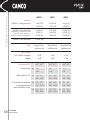
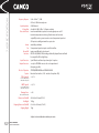
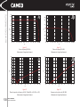
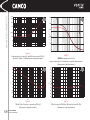
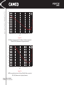
1
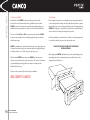
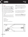
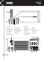
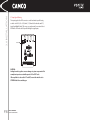
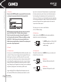
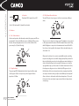
VORTEX OWNER’S MANUAL
FOR VORTEX MODELS: 2.6, 4 & 6
© Copyright 2001 by CAMCO Produktions-und Vertriebs-GmbH
Fischpicke 5, D-57482 Wenden, Germany
Telephone +49 (0)2762 408-0
P.2
CAMCO USER MANUAL
VORTEX POWER AMP SERIES
EXPLANATION OF SYMBOLS
!
CAUTION
!
RISK OF ELECTRIC SHOCK
DO NOT OPEN
CAUTION - HIGH VOLTAGE HAZARDS
EXIST WITHIN THIS PRODUCT.
PLEASE REFER ALL SERVICING TO
AUTHORISED PERSONNEL
THE LIGHTNING FLASH WITH ARROW HEAD SYMBOL, IS INTENDED TO ALERT THE
USER TO THE PRESENCE OF UNINSULATED “DANGEROUS VOLTAGE” WITHIN THE
PRODUCT’S ENCLOSURE THAT MAY BE OF SUFFICIENT OPERATING
MAGNITUDE TO CONSTITUTE A RISK OF ELECTRIC SHOCK TO PERSONS
!
THE EXCLAMATION MARK IS INTENDED TO ALERT THE USER TO THE
PRESENCE OF IMPORTANT AND MAINTENANCE (SERVICING)
INSTRUCTIONS IN THE LITERATURE ACCOMPANYING THE APPLIANCE
!
CAUTION - RISK OF ELECTRIC SHOCK DO NOT OPEN
WARNING - TO PREVENT FIRE OR SHOCK HAZARD, DO NOT EXPOSE THIS
APPLIANCE TO RAIN OR MOISTURE
P.3
CAMCO USER MANUAL
VORTEX POWER AMP SERIES
SAFETY
1.0 Read Owner’s Manual
When shipping the VORTEX amplifier, always use the original shipping carton
and packing materials. For maximum protection, repack the unit as it was
originally packed at the factory.
8.0 Object And Liquid Entry
Never push objects of any kind into this product through openings as they may
touch dangerous voltage points or short out parts that could result in a fire or
electric shock. Never spill liquid of any kind on the product.
2.0 Environments
Use this amplifier only in E1, E2, E3 or E4 environments according EN55103-2.
9.0 Accessories
Do not place this product on an unstable cart, stand, tripod, bracket, or table.
The product may fall, causing serious injury, and serious damage to the
product. Any mounting of the product should follow the manufacturers
instructions, and should use a mounting accessory recommended by the
manufacturer.
3.0 Ventilation
Slots and openings in the cabinet are provided for ventilation, to ensure
reliable operation of the product and to protect it from overheating. These
openings must not be blocked or covered. This product should not be installed
unless proper ventilation is provided or manufacturer’s instructions have been
adhered to.
4.0 Water & Moisture
Do not use this product near water (for example, in a wet basement or near a
swimming pool)
10.0 Connecting
When you connect the amplifier to other equipment, turn off the power and
unplug all of the equipment from the supply source. Failure to do so may
cause an electric shock and serious personal injury. Read the owner’s manual
of the other equipment carefully and follow the instructions when making the
connections.
5.0 Cleaning
Unplug this product from the wall outlet before cleaning. Do not use liquid or
aerosol cleaners.
11.0 Sound Volume
Reduce the volume to minimum before you turn on the product to prevent
sudden high levels which may cause hearing or speaker damage.
6.0 Power-cord Protection
Power-supply cords should be routed so that they are not likely to be walked on
or pinched by items placed upon them or against them, paying particular
attention to cords and plugs, and the point where they exit from the product.
12.0 Damage Requiring Service
Unplug this product from the mains supply and refer to your dealer/distributor
under the following conditions:
When the power-supply cord is damaged
If liquid has been spilled, or objects have fallen into the product
If the product does not operate normally by following the operating
instructions. Adjust only those controls that are covered by the operating
instructions as an improper adjustment of other controls may result in
damage and will often require extensive work by a qualified technician to
7.0 Lightning
For added protection of this product during storms, or when it is left unattended
and unused for long periods of time, unplug it from the wall outlet. This will
prevent damage to the product due to lightning and power-line surges.
P.4
CAMCO USER MANUAL
VORTEX POWER AMP SERIES
SAFETY
restore the product to its normal operation.
If the product has been dropped or damaged in any way.
When the product exhibits a distinct change in performance this indicates
a need for a service.
13.0 Servicing
Do not attempt to service this product yourself as opening or removing covers
may expose you to dangerous voltage or other hazards. Please refer to your
dealer/distributor.
14.0 Replacement Parts
When replacement parts are required, be sure the dealer/distributor uses
replacement parts specified by the manufacturer. Unauthorized substitutions
may result in fire, electric shock or hazards.
15.0 Safety Check
Upon completion of any service or repairs to this product, ask the dealer
distributor to perform safety checks to determine that the product is in proper
operating condition.
P.5
CAMCO USER MANUAL
VORTEX POWER AMP SERIES
EC DECLARATION OF CONFORMITY
EC Declaration of Conformity in accordance to EC Directives:
electro-magnetic compatibility (Council Directive 89/336/EEC,
as amended by Directives 92/31/EEC and 93/68/EEC);
low-voltage electrical equipment (Council Directive 73/23/EEC )
Manufacturers Name:
CAMCO Produktions- und Vertriebs- GmbH
Manufacturers Address:
Fischpicke 5
57482 Wenden
Germany
Declares that the product with the model name:
CAMCO Power amplifier VORTEX 2.6, VORTEX 4 and VORTEX 6
Conforms to the following standards:
EN60065 Security
EN55103-1 Emission
EN55103-2 Immunity
The operating conditions and application environments presupposed
in the operating instruction are to be kept accordingly.
Wenden, 26.10.2000
Joachim Stöcker
P.6
CAMCO USER MANUAL
VORTEX POWER AMP SERIES
CONTENTS
P.7
P.3
P.4
P.6
P.7
P.8
EXPLANATION OF SYMBOLS
SAFETY
DECLARATION OF CONFORMITY CE
CONTENTS
1.0 WELCOME
1.1 Welcome to CAMCO
1.2 Unpacking
1.3 Features (Introduction)
P.10 2.0 FACILITIES
2.1 Front Panel
2.2 Rear Panel
P.11 3.0 INSTALLATION
3.1 ON/OFF Switch
3.2 Precautions
3.3 Mounting
3.4 Cooling
3.5 Ground Lift
3.6 Wiring
3.6.1 SPEAKON Connection
3.6.2 E.U.I. and XLR Connection
3.6.3 Stereo Operation
3.6.4 Bridge-Mono Operation
3.6.5 Parallel-Mono Operation
3.7 Input Signal Parallel Switch on E.U.I.
P.16 4.0 OPERATION
4.1 Precautions
4.2 Controls
4.2.1 Volume Control
4.2.2 Gain Selector
4.2.3 Limiter Switch
4.3 Indicators
4.3.1 On/Failure Indicators
CAMCO USER MANUAL
VORTEX POWER AMP SERIES
4.3.2 Signal Indicators
4.3.3 Clip/Output Current Indicators
4.4 Power Amp Protection Systems
4.4.1 Clip Limiter
4.4.2 Under Impedance Limiter
4.4.3 Speaker Protect Limiter
4.4.4 SOA Protection
4.4.5 DC Protection
4.4.6 DC Servo
4.4.7 Power Amp Over Current Protection
4.4.8 Power Amp Thermal Protection
4.5 Mains Protection
4.5.1 Inrush Current Limitation
4.5.2 Mains Over Voltage Detection
4.5.3 Mains Failure detection
4.5.4 Fuse Protection
4.6 Main SMPS Protection
4.6.1 Main SMPS Over Current Protection
4.7 Fans
4.8 Filter Cleaning
P.21 5.0 OPTIONS
5.1 E.U.I.
5.1.1 Input Signal Parallel Switch
5.1.2 Filter On/Off Switch
5.1.3 Accessories
5.1.4 Using E.U.I.
5.2 C.A.I.
5.2.1 CAMCO Audio Interface
5.2.2 Wiring
5.2.3 CAI - Address Settings
5.2.4 To Activate CAI Address Selection
Procedure
P.23
P.26
P.28
P.32
P.33
P.34
5.2.5 CAI - Status Indicator
5.2.6 Overview or Remote Controls with CAI
6.0 TROUBLESHOOTING
6.1 On LED Flashing Sequences
6.2 Examples of LED Sequences
6.3 Problem: No Sound
6.4 Problem: No Sound or Sound is too Low
6.5 Problem: No Channel Separation
6.6 Problem: Distorted Sound
6.7 Problem: Music Sounds Frequency Filtered
6.8 Problem: Hiss
6.9 Problem: Squeals and Feedback
7.0 SPECIFICATION
8.0 MEASUREMENTS
9.0 WARRANTY INFORMATION
8.1 Summary of Warranty
8.2 Items Excluded from this Warranty
8.3 What CAMCO will do
8.4 How to obtain Warranty Service
8.5 CAMCO’s Product Improvement
10.0 SERVICE INFORMATION
9.1 Owner’s Information
9.2 Nature of Problem
9.3 Expired Warranty
9.4 Shipping Address
11.0 COMPANY INFORMATION
1.0 WELCOME
1.1 Welcome to CAMCO
Established in 1983, CAMCO has gained worldwide experience with
professional sound reinforcement technology. Within the audio market,
CAMCO specialises in the production and marketing of high quality power
amplifiers and sound systems for use both on tour and in static installations.
The success of the LA, DL and DX series power amps has made the CAMCO
name synonymous with professional quality, high performance and utterly
reliable power amps.
CAMCO’s commitment to research and development, seen not just in the area
of materials and technology but also most importantly in its highly skilled and
motivated workforce, is one of the keys to its ongoing success.
With its all-new VORTEX power amp series, CAMCO is pioneering a new
dimension in professional power amp construction. The seamless combination
of groundbreaking technology with secure and proven elements is the
hallmark of the new series.
Welcome to the new world of professional power amplifiers -
WELCOME TO CAMCO!
P.8
CAMCO USER MANUAL
VORTEX POWER AMP SERIES
1.2 Unpacking
Please unpack and inspect your new amplifier for any damage that may have
occurred during transit. If damage is found, notify the transportation company
immediately. Only you the consignee may initiate a claim for shipping damage.
CAMCO will be happy to cooperate fully as needed. Please save the shipping
carton as evidence of damage for the shipper’s inspection.
Even if the amplifier has arrived in perfect condition, save all packing materials
so you will have them if you ever need to transport the unit.
NEVER SHIP THE AMPLIFIER WITHOUT THE ORIGINAL
PACKING MATERIALS.
When shipping the VORTEX amplifier, always use the original shipping carton
and packing materials. For maximum protection, repack the unit as it was
originally packed at the factory.
1.0 WELCOME
1.3 The amplifier
The VORTEX is a Class-H power amplifier with a power output of 3 kW per
channel / 2 Ohm load (6 kW in mono / 4 Ohm load) for VORTEX 6, 2 kW per
channel / 2 Ohm load (4 kW in mono / 4 Ohm load) for VORTEX 4 and 1300 W
per chanel / 2 Ohm load (2,6 kW in mono / 4 Ohm load) for VORTEX 2.6.
It is supplied by Switched Mode Power Supplies (SMPS). These SMPS’s radically
reduce the weight and size (only 2U) of the amplifier. Using SMPS, the 3 symmetrical supply voltages (2- symmetrical supply voltages for VORTEX 2.6)
of the power amplifier are more stable than the power supplies used in conventional amplifiers.
The VORTEX also uses a microprocessor for controlling and monitoring the
power amp. Controlling a power amp designed for use in modern sound
systems, has four main advantages over more traditional power amp systems:
Reduced Distortion
Improved Noise Characteristics
Integrated Remote Control
Indication of protection or failures by different LED sequences
P.9
CAMCO USER MANUAL
VORTEX POWER AMP SERIES
The VORTEX has been designed as an intelligent and powerful product for
performing specialised tasks within a complex audio system. Users can adapt
the power amp to meet their specific audio requirements before use. Controls
mounted on the front and the rear of the VORTEX allow access to the
functionality.
Since some of the externally mounted controls have multiple functions, it is
important that users should familiarise themselves with the entire range of
controls and programmable features before using the power amp.
If you have questions about features of the VORTEX power amp that are not
covered by the basic descriptions in this manual, CAMCO would be pleased to
offer you further information. Alternatively, contact your dealer/distributor.
2.0 FACILITIES
9 10 11
1
2
3
VORTEX - The Front
1 ON / OFF Switch
2 Volume Control - Channel A
3 Volume Control - Channel B
4 On / Failure Indicators
5 Signal Indicators
6 Clip / Output Current Indicators
4 56
7
7 Removable Air Filter System
8 Cooling Air Inlet Vents
9 Enter-Switch (behind Front Panel)
10 Operating Mode Indicators
11 CAI Status Indicator
13
12
P.10
CAMCO USER MANUAL
VORTEX POWER AMP SERIES
14
8
15
VORTEX - The Rear
12 AC Power Cable
13 CAMCO Audio Interface (C.A.I.)
14 Speakon Connectors
15 Cooling Vents
16 Input Ground Lift Switch
17 Operating Mode Selector
18 Limiter Switch
19 Gain - Selector
20 Extended User Interface (E.U.I.)
21 XLR - Line Inputs
22 XLR - Line Outputs
16
17
18
19
21
22
22
21
20
411,0 mm
P.11
CAMCO USER MANUAL
VORTEX POWER AMP SERIES
3.3 Mounting
Use four screws and washers when mounting the amplifier to the front rack
rails. Rear support is also recommended, especially in mobile and touring use.
10,5 mm
465,0 mm
442,0 mm
3.2 Precautions
When mounting or connecting the amp always disconnect it from mains.
436,0 mm
427,0 mm
76,2 mm
10,5 mm
88,1 mm
3.0 INSTALLATION
3.1 On/off Switch
NOTE: This switch does not isolate the appliance from mains.
It initiates start-up by activating the inrush current limiter. When the amp is
connected to mains, only the line-filter and the input of the silicon controlled
rectifier (fused) are energised.
76,2 mm
3.0 INSTALLATION
3.4 Cooling
Under normal operation of the power amp, overheating should never be a
problem. The temperature of the cooling air will depend on the immediate
environment (e.g. an enclosed rack, direct sunlight) and on whether the front
filter is clogged. If the amp is installed in a case, the open area at the back of
the case must be at least 140 cm². This area should be in line with the amp.
If this can not be achived a forced ventilation system has to be used.
The air is taken in from the front and out through the back, it is of course
essential that while the power amp is running air is able to circulate around
it freely.
3.5 Ground Lift
The input signal ground (pin 1 for all 4 XLR’s) is tied to the ground potential
in the mains supply. Opening the ground lift switch causes this connection
to be broken. This allows ground loops that sometimes occur in practice to
be eliminated. The ground potential of the power amp and therefore of the
loudspeaker outputs is independent of the switch setting and remains at the
ground potential of the mains supply.
Removing the mains connector ground - as often practiced - is not only illegal
but pointless too, since in practice it never produces any improvement!
DO NOT REMOVE MAINS CONNECTOR GROUND
IT IS ILLEGAL AND DANGEROUS
P.12
CAMCO USER MANUAL
VORTEX POWER AMP SERIES
3.6 Wiring
3.6.1 SPEAKON Connection
4 Ohm speaker cabinets in parallel
Use the contacts in both SPEAKON connectors for each channel. If not, this may
cause permanent damage of the connectors, depending on the music material.
INPUT
CHANNEL A
UPPER SPEAKON
CH. A
CH. B
INPUT
CHANNEL B
BOTTOM SPEAKON
3.0 INSTALLATION
3.6.2 E.U.I. and XLR Connection
XLR: Pin 1 Ground (or lifted via 15 Ohm resistor)
Pin 2 Hot
Pin 3 Cold
Always use symmetrical (balanced) shielded cable to connect the amplifier
wherever possible.
To Gnd
Lift Switch
3.6.3 Mode Indicators
On the front panel there are two yellow LED’s to indicate the mode that is set.
In stereo mode none of them will be lit. In Parallel Mono the (PM) LED will be lit
and in Mono Bridge, the (MB) LED will be lit.
To Ch. A
input stage
To Ch. B
input stage
S1
Stereo = Open
Input signal chaining = Close
3.6.4 Mode Switch
The switch on the rear panel changes the operating mode. Moving this switch
will shutdown the amplifier and restart it in the new operating mode.
3
3
1
2
2
INPUT
CHANNEL B
P.13
CAMCO USER MANUAL
VORTEX POWER AMP SERIES
3
1
2
3
1
1
INPUT
CHANNEL A
2
3.0 INSTALLATION
3.6.5 Stereo Operation
Two fully independent amplifier channels (normal operating mode).
MODE
BRIDGE
STEREO
PARALLEL
MONO
VORTEX
WARNING!
RMS output voltages as high as 230 V are available at the output.
Wiring to the speaker loads must conform to NEC Class 3 safety standards.
3.6.7 Parallel-Mono Operation
Parallel operation of the two channels together.
MODE
BRIDGE
STEREO
PARALLEL
MONO
VORTEX
3.6.6 Bridge-Mono Operation
One-channel mono bridged operation.
MODE
BRIDGE
STEREO
PARALLEL
MONO
VORTEX
The second channel processes the same input signal, but with reversed phase.
The (single) load is connected between the two positive channel outputs using
a suitable connected SPEAKON connector. While the total output of the amplifier remains the same, both the available output voltage and the minimum
impedance that can be connected are doubled, as compared with stereo operation. Only Channel A-Input is active. A signal feeding Channel B will have no
effect on the output.
P.14
CAMCO USER MANUAL
VORTEX POWER AMP SERIES
The output terminals of the two channels are configured in parallel using an
internal relay. The (single) load is connected either to the output of channel 1
or to that of channel 2 (as if in stereo). While the total output of the amplifier
remains the same and the output voltage level is also the same as in stereo
operation, the minimum impedance that can be connected is reduced by half
due to the fact that current capability is doubled. Only Channel A-Input is
active. This mode is useful when powering 3 speaker cabinets in parallel. A load
balancing is achieved in this case.
NOTE: For parallel mono operation, to prevent damage of one SPEAKON
connector and to reduce loss of power because of contact or cable
resistance, it is highly recommended to wire speaker loads using
both 2 channel SPEAKON connectors with all contacts connected.
3.0 INSTALLATION
3.7 Input Signal Chaining
The input signals to the XLR connectors can be hard-wired in parallel using
a switch on the E.U.I. (See 3.6.2, Switch 1, 5.1, Extended User Interface and 5.1.1,
Input Signal Parallel Switch). This serves as a replacement for an external short
XLR female - XLR male cable for parallel linking the signal inputs.
Switch S1
CAUTION:
Linking channels together can cause damage to system components if for
example two inputs are used with separate ‘LF’ and ‘HF’ feeds.
If the amplifier is to be used for ‘LF’ and ‘HF’, ensure this switch is set to
STEREO Mode before switching on.
P.15
CAMCO USER MANUAL
VORTEX POWER AMP SERIES
4.0 OPERATION
4.1 Precautions
Only connect the VORTEX amplifier to a appropriate AC circuit and outlet,
according to the requirements indicated on the rating plate label.
improved noise characteristics. The implementation is comparatively simple:
the volume potentiometers pass the relevant control information (quieter or
louder depending on the adjustment made to the potentiometers) to the
microprocessor. The microprocessor then adjusts the power amp output using
various strategies implemented in software. In addition to improved technical
parameters, this approach allows a significant reduction in the number of
components and circuits required.
The volume pots are also used to set the CAI-address.
(See 5.2.3, CAI Address Settings)
NOTE: Even under normal conditions the mains current can reach levels
(up to 60 A / 230 V and 120 A / 115 V); this could cause lamps to
flicker if connected to the same mains as the amp. The impedance of
the AC circuit should be less than 0,157 Ohms to avoid flicker according
to EN61000-3-11. Ask / inform your local power provider. Don’t even
think about measureing this with your ohmmeter. This may damage your
meter, caution - high voltage hazards!
4.2.2 Gain Selector
A switch on the rear of the VORTEX allows the maximum amplification
attainable to be set directly in the input stage.
GAIN
26dB
4.2 Controls
4.2.1 Volume Control
A microprocessor-controlled DCA (Digital Controlled Attenuator) with a control
resolution of 12 bits per channel is integrated into the signal path. This means
that the signal is not subject to an A/D followed by a D/A conversion with
associated losses. Each channel is governed by a linear potentiometer with 41
notched settings. These settings have been selected to correspond to human
hearing characteristics (logarithmically) and therefore guarantee an optimal
range of settings for practical applications. Each channel can be set individually
except when operating in mono mode whereby only ChA is active.
Using an intelligent DCA control (Digital Controlled Attenuator) instead of
the “conventional” VCA results in considerably reduced distortion as well as
P.16
CAMCO USER MANUAL
VORTEX POWER AMP SERIES
32dB
1.4V
The VORTEX amplifier has a 26 dB and 32 dB
voltage gain setting along with a 1.4 V
sensitivity setting.
4.2.3 Limiter Switch
This switch is located at the rear of VORTEX. It allows you to set the mode of
the limiter. There are three modes:
Right position:
Clip Limiter: ON & Speaker Protect: ON
LIMITER
OFF
SpP
SpP Clip
Middle position:
Clip Limiter: OFF & Speaker Protect: ON
LIMITER
OFF
SpP
SpP Clip
4.0 OPERATION
LIMITER
OFF
SpP
SpP Clip
Left position:
Clip Limiter: OFF & Speaker Protect: OFF
(See 4.4.1,Clip Limiter and 4.4.3, Speaker Protect Limiter)
4.3 Indicators
4.3.1 On / Failure Indicators
Under normal operation, after the amp has started, the green power LEDs are
permanently lit. A variety of different sequences of flashing LEDs are used to
indicate other operating states and errors in one of the channels of the
power amp. (See 6.0, Trouble Shooting)
4.3.2 Signal Indicators
The green signal LED is illuminated when the voltage level at the output
reaches approx. 4 V; this corresponds to a power of approx. 4 W at an
impedance of 4 Ohms.
P.17
4.3.3 Clip / Output Current Indicators
The clip LED’s are bi-coloured: green / red. Each colour indicates a different
status.
CAMCO USER MANUAL
VORTEX POWER AMP SERIES
The green section is subject to analogue control. The brightness is proportional
to the output current in the channel. The LED is visibly lit above around 1 Amp,
while full brightness corresponds to the maximum rated current. If the LED is
lit red only, no load is applied to the outputs or Clip is active with a duty cycle
of more than 10 %.
When under load, there is also a certain current that flows when controlling
the power level; the green section will be lit appropriately. If the power level is
taken to the limit, the green and red sections will appear mixed, resulting in a
shade of yellow that depends on the current. If the microprocessor detects a
clip signal with a duty cycle of more than 10 % within a time interval of 50 ms,
then it suppresses the green section so that the clip LED appears only red.
Careful analysis of the various dependencies when comparing channels that
are subject to identical control (possibly in several different power amps) will
allow conclusions to be drawn about the inherent impedances. This can aid
the detection of incorrectly wired components and faults in loudspeakers at
an early stage.
4.0 OPERATION
4.4 Power Amp Protection Systems
4.4.1 Clip Limiter
If the power amp is overdriven, the clip detection circuit triggers the microprocessor. The processor reduces input signal level by controlling the DAC.
The strategy is implemented in software. For sinusoidal signals the
microprocessor limits the input signal level with the result that the non-linear
distortion factor never exceeds 1 %.
The clip limiter can work on each channel independently (except in monooperation).
To disable the Clip Limiter, see 4.2.3, Limiter Switch.
4.4.2 Under Impedance Limiter
As a result of incorrectly connected or defective loads, under impedance or
even short circuits may be presented to one or both power amp channels. In
order to detect an under impedance, the microprocessor calculates the resultant impedance. If an impedance of less than 1.33 ohms/channel is detected, the
microprocessor limits the signal to the power amp until a subsequent
measurement indicates that impedance has risen to a safe level. Whenever the
under impedance limiter is active, the corresponding channel’s power LED is
turned off. (See 6.0, Trouble Shooting)
4.4.3 Speaker Protect Limiter
Whenever the Safe Operation Mode (SOA) protection of the power amp
switches back the current rail there could be a small clipping at the output;
but the microprocessor is also triggered by this protection and will reduce the
signal level immediately to minimise the effect.
User can decide either to use speaker protect or not. When you use this amp
for low frequencies (SUB bass / bass) and you want to squeeze the absolute
P.18
CAMCO USER MANUAL
VORTEX POWER AMP SERIES
maximum out of it, switch Speaker Protect off. For all other applications (e.g.
Full Range) it’s recommended to switch Speaker Protect on.
4.4.4 SOA Protection
Whenever the power transistors leave their Safe Operation Area (SOA), the
SOA-protection in stereo mode switches back the current rail of the respective
power stage. In mono modes the rails of both channels are switched back.
4.4.5 DC Protection
Each output of the power amp is constantly monitored for persistent DC
voltage levels. If the 3 V thresholds are exceeded at any of the outputs, the
channel at that output will be automatically disconnected. The microprocessor
performs a sophisticated strategy to locate the cause of DC. If short-term DC is
detected, the amplifier will recover and continue to operate. DC can be located
in the Output stage, Driver stage or at the input of the amplifier.
Output stage
When DC is located in either output stage, the amp stops the main SMPS
and mutes the amp where DC was detected. The On-LEDs will show a
different flash sequence. (See 6.0, Trouble Shooting)
Driver stage
When DC is located in the driver stage only the defective channel’s output
stage and DCA are muted. The other channel still works. The On-LED of the
defective channel will start the flash sequence. (See 6.0, Trouble Shooting)
Amplifier Input
When DC is located at the input stage only the DCA of the affected channel
is muted. (The other channel continues to operate normally). If the DC
signal at the input vanishes the microprocessor will de-mute the affected
channel and the amplifier will work as usual again.
4.0 OPERATION
4.4.6 DC Servo
To Prevent DC-Offset at the Speaker output the VORTEX is fitted with two
DC-Servos. (Hence there are no capacitors in the signal path!)
4.4.7 Power Amp Over Current Protection
Over current is permanently controlled in the output stage. There are two
limiting levels of over current depending on output voltage. These limits will
be set automatically. This improves reliability without degrading sound quality
when driving complex loads.
4.4.8 Power Amp Thermal Protection
The microprocessor uses several sensors in the amp in order to ascertain
temperature data. If the microprocessor detects a temperature of more than
85 °C at the heat sinks, the input signal on that channel is reduced.
The power LED of the overheated channel will start a blinking-sequence
(See 6.0, Trouble Shooting)
4.5 Mains Protection
4.5.1 Inrush Current Limitation
Within 2 seconds of the amplifier being switched on, the inrush current limiter
will increase mains current from nearly zero to nominal value. This value
depends on program material, output level and speaker loads.
4.5.2 Mains Over Voltage Detection
Mains over voltage detection is always operative. When the mains voltage
exceeds approx. 267 V (230 V operation) or 134 V (110 V operation), the amplifier will be switched off. When the mains voltage returns to nominal value, a
soft start occurs.
P.19
CAMCO USER MANUAL
VORTEX POWER AMP SERIES
4.5.3 Mains Failure Detection
Mains failure detection is always operative. When the mains supply is
interrupted for about 2 mains cycles, the amplifier will be switched off. When
the mains voltage returns to a normal value, a soft start occurs.
4.5.4 Fuse Protection
Depending on the load impedance and type of signal levels, the effective
mains current can, even during normal operation, reach a level several times
higher than its nominal value for short periods. Repeated peaks of this nature
will also cause the average value to increase. In such cases, the internal mains
fuse and external 16 A circuit breaker acts as a “bottleneck”, and would trip if the
average current remained too high for an extended period. In order to avoid
this unsatisfactory operation, the mains fuse is simulated inside the amplifier
and provides the microprocessor with information. Prior to the point when the
circuit breaker would trip, a signal is sent to the microprocessor, which then
instantaneously reduces the signal level. After the known recovery time for the
fuse has elapsed, the signal is again adjusted to its normal level. This offers
reliable operation of a 6 kW VORTEX on 16 A Mains at 230 V and
30 A at 115 V.
4.6 Main SMPS Protections
4.6.1 Main SMPS Over Current Protection
Main SMPS (Switched Mode Power Supply) Transformer current is continuously
monitored. If over current occurs, the main SMPS immediately stops working.
Should there be an internal failure, this feature prevents other parts being
damaged.
4.0 OPERATION
4.7 Fans
The fans mounted in the VORTEX operate permanently, but as long as the temperature remains below 40 °C they run at their slowest speed and can hardly be heard.
The highest detected temperature from either channel controls the speed of the fans: above 40 °C the speed is increased until it reaches its maximum value.
4.8 Filter Cleaning
A removable filter system is provided on the air intakes to the cooling system. If the filter becomes clogged, the unit will not cool as efficiently as it should and may
produce output levels that are lower than normal due to high heat sink temperatures.
To clean, gently slide the whole plastic filter assembly to the left and release from the front panel. Carefully unclip the outer moulding to reveal the filter. Clean the filter
with a mild dishwashing detergent and warm water. Once dry, insert the filter back into the cradle and cover with the surround moulding. Slide the whole assembly to
the right to secure onto the front panel.
Spare filter assembly’s may be ordered from your dealer.
3
4
5
VORTEX Filter Assembly
1 Clip Apertures
2 Injection Moulded Cradle
3 Foam Filter
4 Injection Moulded Surround
5 Injection Moulded CAMCO Badge
1
2
P.20
CAMCO USER MANUAL
VORTEX POWER AMP SERIES
5.0 OPTIONS
5.1 E.U.I. (Extended User Interface)
The E.U.I. slot contains the Rear XLR Panel and the Input Signal Parallel switch
as standard. Other input cards are available (See 5.1.3 Accessories) Always switch
off and unplug the VORTEX from mains, when working on the E.U.I.
The switches described below are not readily accessible and cannot be
checked visually from the outside. To remove the E.U.I. unscrew the two Phillips
head screws at the left and right end of XLR-Panel and carefully slide out the
E.U.I. To refit the E.U.I into the VORTEX, carefully insert the PCB in the guide-rail
(left/right) and slide it in.
Don’t forget to replace the screws!
5.1.1 Input Signal Parallel Switch
If you want to hard-wire the XLR input connectors together on the E.U.I., just
change from Stereo to Mono using switch S1. Be careful when you do this!
(See section 3.7, Input Signal Chaining)
5.1.2 Filter On / Off Switch
If a filter is present on the E.U.I. this can be activated or bypassed using switch
S2.
Switch S2
P.21
CAMCO USER MANUAL
VORTEX POWER AMP SERIES
5.1.3 Accessories
Different types of filters are available. For further information contact your
dealer or CAMCO
5.1.4 What Are The Possibilities Using The E.U.I.?
The E.U.I. is a very powerful interface, which allows access to most of the system
parameters. For example: volume, input signal, mute, output current, clip signal,
temperature and more. It makes it possible to utilise filters, remote control,
signal processing, and more… Please contact your dealer or CAMCO to
customise the E.U.I. according your wishes.
5.2 C.A.I. (Camco Audio Interface)
5.2.1 Camco Audio Interface
C.A.I. is a bus system, in which all significant device functions can be monitored
externally and remotely controlled using a master PC. Up to 99 devices can be
controlled in parallel in each phase of the bus system, which simply consists
of a two-core insulated cable. The master can serve several phases for larger
applications. For more information, please contact your dealer or distributor.
5.2.2 Wiring
To connect the VORTEX to your C.A.I. - system use a fully-wired telephone-type
cable with RJ12 connectors. For longer distances use high grade cable like
for RS485, DMX512 for AES/EBU digital audio. You can chain several VORTEX
amplifiers using the second C.A.I. Connector on each amplifier. A linear network topology is recommend with 100 Ohm termination at its end. Please refer
to RS 485 specifications.
5.2.3 C.A.I. Address Settings
The C.A.I. address selection procedure will not affect the operation of the
VORTEX but whilst this procedure is active, the Volume cannot be adjusted by
using the Pots.
5.0 OPTIONS
NOTE: Ensure you return both pots to their original position after address
selection is complete, otherwise the amplifier will change its volume level
to the new pot positions!
5.2.4 To Activate CAI Address Selection Procedure
Briefly press the ENTER -Switch. This push button switch (Enter - Switch) can be
accessed through the 3mm hole in the front panel located between the main
power switch and the LEDs.
Enter Switch
After briefly pressing the Enter-Switch the actual address will be displayed by
the power LEDs.
Flashing of Power LED channel A indicates the tens,
Flashing of Power LED channel B indicates the units of the address.
For example: different address setting LED sequences:
P.22
Address
Power LED Channel A/ TENS
Power LED Channel B/ TENS
01 (factory settings)
0* flash
1* flash then short pause
25
2* flashes then short pause
5* flashes then short pause
CAMCO USER MANUAL
VORTEX POWER AMP SERIES
These sequences are repeated for 30 seconds (timeout). Then the Power LEDs
return to their normal function.
To change CAI address, turn the appropriate Volume Potentiometer to the
required address (Volume Pot Ch A => TENS, Volume Pot Ch B => UNITS).
To adjust the address you can use the scale markings of the
potentiometers. You will find the digits 0,1,2,3,4,5,6,7,8,9 on the 10 scale
spacing .
The current selected address will be immediately displayed BUT not automatically stored or activated! After each turn of pot you have another 30 seconds
to timeout. You can leave this procedure without saving the new address by
briefly pressing the Enter-Switch or waiting for timeout (as described above).
To store and activate the new address you have to press the Enter-Switch for
3 seconds. This new address is stored in an EEPROM, which holds the information even if the amp is subsequently disconnected from mains. Be sure to
set the CAI-Master-PC to this new address. If not, the communication will be
interrupted.
5.2.5 CAI Status Indicator
This green LED indicates the presence of communication between PC and the
amp.
5.2.6 Overview Or Remote Controls CAI
CAI allows:
To control the output-level of each channel independently
(exception: mono modes, only channel A is affected)
To mute each channel independently
(exception: mono modes, only channel A is affected)
To switch the VORTEX into STANDBY mode (and back again)
To monitor temperature, output-signal, clip, output-current.
6.0 TROUBLESHOOTING
6.1 On LED Flashing Sequences
When switching on the amp the Power LEDs flash twice accompanied by a
flash of clip LEDs. This is normal for the ‘Start’ sequence of the VORTEX.
When switching off the amp the Power LEDs flash several times followed by a
flash of clip LEDs. This is normal for the Shut Down sequence of the VORTEX.
(It is the same as the loss of the mains voltage.)
In the following table you will find the possible LED sequences of the ON-LEDs:
Operating Status
Normal (no failure)
Power fail
(i.e. switch off )
LED sequence:
Failure:
Description of repeated sequences
Permanently lit
. . . X-------------------X-------------------X-------------------X . . .
Short 50 ms flash + 950 ms pause
High Temperature:
signal attenuation
. . . -XXX-XXX-XXX-XXX-XXX-XXX-XXX-XXX-XXX-…
750 ms flash + 250 ms pause
Over Temperature:
main SMPS off
…X---X---X---X---X---X---X---X---X---X---X---X---…
250 ms flash + 750 ms pause
DC:
reason unknown
…-X-X-X-X-X-X-X-X-X-X-X-X-X-X-X-X-X-X-X-X-X-…
250 ms flash + 250 ms pause
DC:
input-signal-fault
. . . ---X-X-X---X-X-X---X-X-X---X-X-X---X-X-X---…
3 * flashing + 0.5 s pause
DC:
fault in driving-stage
. . . ---X-X-X-X---X-X-X-X---X-X-X-X---X-X-X-X---…
4 * flashing + 0.5 s pause
DC:
power-stage defect
. . . ---X-X-X-X-X---X-X-X-X-X---X-X-X-X-X---…
5 * flashing + 0.5 s pause
Power-stage defect
without DC
. . . ---X-X-X-X-X-X---X-X-X-X-X-X---X-X-X-X-X-X---. . .
6 * flashing + 0.5 s pause
. . . ---X-X---X-X---X-X---X-X---X-X---X-X---X-X--- . . .
2 * flashing + 0.5 s pause
Main SMPS off:
(unless Hi Temp/Power Fail)
P.23
LED Sequence (X) = flash, (-) = off
6.2 Examples of LED Sequences
LED sequence:
Ch1 : …XXX-XXX-XXX-XXX-XXX-XXX-XXX-XXX-XXX-…
Ch2 : …………..Permanently lit……………
Failure:
Ch1: high temperature with signal attenuation
Ch2: normal operation
CAMCO USER MANUAL
VORTEX POWER AMP SERIES
Ch1 : . . X-X-X-X-X---X-X-X-X-X---X-X-X-X-X---. . . . . .
Ch2 : . . X-X---X-X---X-X---X-X---X-X---X-X---X-X---. . .
Ch1: DC, power-stage defect
Ch2: main SMPS off
6.0 TROUBLESHOOTING
6.3 Problem: No Sound
Indication: On LEDs not lit
Clip/Output Current Indicators not lit
Check AC plug.
Confirm that AC outlet works by plugging in another device.
Indication: On LEDs lit
Signal LEDs not lit
Make sure the signal source is operating and try another cable.
Check Position of Volume Pots.
Indication: On LEDs lit
Signal LEDs responding to signal level
Check the speaker wiring for breaks.
Try another speaker and cable.
Indication: On LED(s) sequence
The amplifier is in protective muting. Refer to On LED flashing sequences table to find out the cause for the mute.
Overheating will cause protective muting.
Check for proper ventilation. If the fan isn’t running the amplifier requires
servicing.
6.4 Problem: No Sound or Sound is too Low
Indication: On LED not or sporadically lit
Signal LED off
Clip/Output Current indicator lit green or red
Under Impedance Limiter is active. The load impedance is
abnormally low or shorted.
Unplug each speaker one-by-one. If the On LED indicates normally when
you disconnect a cable, that cable or speaker is shorted.
Take care not to use too many speakers in parallel, which would result in -
P.24
CAMCO USER MANUAL
VORTEX POWER AMP SERIES
an impedance that is too low for normal operation!
Indication: On LED(s) Sequence
Please refer to the On LED sequence table to find out which
protection is active.
High temperature will cause an attenuation of output level so that under
normal conditions the amp will never mute!
DC will cause the amp to mute or shut down.
Switch off the VORTEX and unplug the source from the amp’s input to
prevent DC entering the amp via the signal source. Then switch on the
VORTEX. If the On-indicator shows the same sequence, the amp will need to
be serviced by a qualified technician.
All other LED sequences that shut down or mute the VORTEX indicate a
serious internal fault. At this point, turn the VORTEX off, remove AC power
and have the amplifier serviced by a qualified technician.
6.5 Problem: No Channel Separation
Check the mode indicators on the front panel.
Make sure the mode-switch on the rear panel is in the stereo-position.
Make sure other equipment in the signal path such as mixers and preamps
are set for stereo, not mono.
On the E.U.I., check the Input Signal Parallel Switch is in the stereoposition.
6.0 TROUBLESHOOTING
6.6 Problem: Distorted Sound
Indication: On LED lit
Signal LED responding to signal level
Clip/Output Current indicator lit only green
A faulty speaker or a loose connection could cause this. Try another
speaker and check the wiring.
The signal source might be clipping. Keep the VORTEX volume pots at
least halfway up so that the source does not have to be overdriven.
Try changing input sensitivity from 1,4 V to 32 dB or 26 dB at the
Gainswitch.
6.7 Problem: Music Sounds Frequency Filtered
If you have installed an optional filter module on E.U.I check the filter
on/off-switch to be in off-position.
6.8 Problem: Hiss
Unplug the amplifier input to confirm that the hiss is coming from the
source or from a device upstream.
Erratic or popping noises indicate an electronic fault in the
offending unit.
To keep the noise floor low, operate the primary signal source at full level,
without clipping.
Avoid boosting the signal further between the source and the
amplifier.
6.9 Problem: Squeals and Feedback
Microphone feedback should be controlled with mixer controls. If noise
continues to build up with no microphone gain, there is a serious fault in
the signal processors or cables. Working in succession from the signal source
towards the amplifier and check each device in the signal path by reducing
its gain or by unplugging it.
P.25
CAMCO USER MANUAL
VORTEX POWER AMP SERIES
7.0 SPECIFICATION
VORTEX 2.6
VORTEX 4
VORTEX 6
1 x 2600 W / 4 Ω
1 x 1500 W / 8 Ω
1 x 4000 W / 4 Ω
1 x 3000 W / 8 Ω
1 x 6000 W / 4 Ω
1 x 4200 W / 8 Ω
1 kHz, THD < 0,1 %, both channels driven
2 x 1300 W / 2Ω
2 x 750 W / 4 Ω
2 x 450 W / 8 Ω
2 x 2000 W / 2Ω
2 x 1500 W / 4 Ω
2 x 920 W / 8 Ω
2 x 3000 W / 2Ω
2 x 2100 W / 4 Ω
2 x 1200 W / 8 Ω
1 kHz, THD < 1 % , both channels driven
2 x 1500 W / 1,8 Ω
Bipolar, Class H 2-step
high efficiency circuit
Bipolar, Class H 3-step
high efficiency circuit
Bipolar, Class H 3-step
high efficiency circuit
>103 dB
>105 dB
>107 dB
>106 dB
>108 dB
>110 dB
Typical 1) Max 2)
Typical 1) Max 2)
Typical 1) Max 2)
Output Power
1 kHz, THD < 0,1 % , in bridged mono mode
Duration limited by fuse / thermal protection for RL < 8 Ohm
in stereo mode or RL < 16 W in bridged mono mode
Measurement at 2 Ohm without preconditioning (EN 60269-3)
Circuitry
Signal to Noise-Ratio
20 Hz - 20 kHz, 8 Ω load, unweighted
A-weighted
Power Consumtion @ 230 V
1)
P.26
(both channels driven)
Idle
1A/
60 W
Multiply currents by 2 for 115 V
8Ω
3A/
320 W
1/8 of max Output Power with pink noise
to represent typical music signal
2) max. rated Output Power (see above)
4Ω
1.8 Ω
CAMCO USER MANUAL
VORTEX POWER AMP SERIES
Idle
0,8 A /
50 W
Idle
1A/
60 W
9A/
1250 W
8Ω
4,4 A /
550 W
16,2 A /
2500 W
8Ω
5,5 A /
700 W
21 A /
3200 W
4,3 A /
510 W
15 A /
2200 W
4Ω
6,5 A /
880 W
28 A /
4300 W
4Ω
8A/
1100 W
35 A /
5800 W
7,2 A /
1005 W
30 A /
4800 W
2Ω
10 A /
1450 W
40 A /
6600 W
2Ω
12 A /
1800 W
60 A /
9400 W
7.0 SPECIFICATION
Frequency Response
Input Impedance
Voltage Gain
Protection Circuits
Limiter
Fan
Ground-Lift
Indicators
Input Connectors
Output Connectors
Modes of Operation
Options
THD+N (typical)
20 Hz - 10 kHz, 8 Ω load
3 dB below rated power
SMPTE (typical)
20 Hz - 20 kHz, 8 Ω load
3 dB below rated power
Damping Factor
8 Ω load, 1 kHz and below
Dimensions (WxHxD)
Net Weight
Shipping Dimensions (WxHxD)
Shipping Weight
20 Hz - 20 kHz ± 0,15 dB
8 Ω load, 1 dB below rated power
40 kΩ balanced
selectable: 26 dB, 32 dB, or 1,4 V input sensitivity
inrush-current limitation, protection circuits against power on/off
transients, temperature monitoring of transformers and heat-sinks,
output DC protection, power transistor control, temperature dependent
SOA protection, intelligent mains fuses protection
switchable peak-limiter
2 temperature dependent speed-controlled axial fans
input ground-lift switch on back panel
LED’s for ON, SIGNAL, CLIP, indicating additionally Output Current and faults
for example like DC and High Temp
3-pin XLR, male and female per channel, pin 2 = inphase
one 4-pole SPEAKON connector for each output channel
(bi-amping possible)
STEREO, BRIDGE MONO and PARALLEL-MONO
Extended User Interface / E.U.I. - modules for any kind of EQ
< 0,01 %
< 0,01 %
> 400
483 x 88,9 x 420 mm (19”, 2U)
12,4 kg
600 x 600 x 205 mm (0,074 m3)
15 kg
Subject to technical alterations without prior notice
P.27
CAMCO USER MANUAL
VORTEX POWER AMP SERIES
+150
+26
+100
+25.5
+25
+50
+24.5
+24
deg
dBr
8.0 MEASURMENTS
+27
+26.5
+23.5
+23
+22.5
-100
+22
+21.5
+21
10
+0
-50
-150
20
50
100
200
500
Hz
1k
2k
5k
10k
20k
50k 100k
10
20
50
1k
2k
5k
10k
20k
50k 100k
-40
-20
-50
-30
-60
-40
-70
-50
-60
-80
dBr
dBr
500
Figure 7.3
Phase vs. frequency (Ch1, Ch2)
(Measurements of a typical performance)
-10
-70
-80
-90
-100
-90
-110
-100
P.28
200
Hz
Figure 7.1
Gain vs. frequency (Ch1, Ch2)
(Measurements of a typical performance)
-110
20
100
50
100
200
500
1k
2k
5k
10k
20k
-120
20
50
100
200
500
1k
2k
Hz
Hz
Figure 7.2
Channel separation vs. frequency @ 10 W / 4 Ohm (Ch1 => Ch2, Ch2 => Ch1)
(Measurements of a typical performance)
Figure 7.4
Common mode rejection ratio (Ch1, Ch2)
(Measurements of a typical performance)
CAMCO USER MANUAL
VORTEX POWER AMP SERIES
5k
10k
20k
1000
100m
800
Damping factor
50m
Ohm
8.0 MEASURMENTS
300m
200m
20m
10m
5m
400
200
2m
20
50
100
200
500
1k
2k
5k
10k
20k
Hz
0
20
50
100
200
500
Hz
1k
2k
5k
10k
20k
Figure 7.7
VORTEX 6 damping factor into 8 Ohm
equation: damping factor= loaded impedance / amplifier output impedance
(Measurements of a typical performance)
-20
-20
-30
-30
-40
-40
-50
-50
-60
-60
-70
-70
dB
dB
Figure 7.5
Output impedance vs. frequency @ 1 Amp RMS injected current. (Ch1, Ch2)
equivalent 11 mOhm + 2.1uH (Measurements of a typical performance)
-80
-80
-90
-90
-100
-100
-110
-110
-120
100u 200u
500u 1m
2m
5m 10m 20m
Vrms
50m 100m 200m
500m
1
Figure 7.6
THD+N @ 1 kHz, 4 Ohm load vs. input voltage (Ch1, Ch2)
(Measurements of a typical performance)
P.29
600
CAMCO USER MANUAL
VORTEX POWER AMP SERIES
2
6
-120
20
50
100
200
500
Hz
1k
2k
5k
Figure 7.8
THD+N vs. frequency (BW 22 kHz), 3 dB below clip, 4 ohms (Ch1, Ch2)
(Measurements of a typical performance)
10k
-30
-40
-50
-60
dB
8.0 MEASURMENTS
-20
-70
-80
-90
-100
-110
-120
100u 200u
500u 1m
2m
5m 10m 20m
50m 100m 200m
500m
1
2
6
Vrms
Figure 7.9
CCIF difference frequency method (10,5 kHz and 11,5 kHz) vs. inputlevel @
4 Ohms (Ch1, Ch2) (Measurements of a typical performance)
-20
-30
-40
-50
dB
-60
-70
-80
-90
-100
100u 200u
500u 1m
2m
5m 10m 20m
50m 100m 200m
500m
1
2
Vrms
Figure 7.10
SMPTE intermodulation distortion (60 Hz and 7 kHz) @ 4 Ohm vs. input level
(Ch1, Ch2) (Measurements of a typical performance)
P.30
CAMCO USER MANUAL
VORTEX POWER AMP SERIES
6
8.0 MEASURMENTS
5000
4000
3000
3090
2000
2113
2000
Distortion limited
output power
1458
Peak power
1257
1000
Peak power
0
2
Impedance (Ohms)
4
Distortion limited
output power (0,1 % THD)
8
988
1000
755
Watts
528
450
Distortion limited
output power
Peak power
Peak power
0
2
Impedance (Ohms)
4
8
Distortion limited
output power (0,1 % THD)
Figure 7.12
VORTEX 2.6 (Measurements of a typical performance)
P.31
CAMCO USER MANUAL
VORTEX POWER AMP SERIES
1000
Distortion limited
output power
1084
Peak power
931
Peak power
0
2
4
8
Distortion limited
output power (0,1 % THD)
Figure 7.13
VORTEX 4 (Measurements of a typical performance)
1760
1305
1549
Watts
Impedance (Ohms)
Figure 7.11
VORTEX 6 (Measurements of a typical performance)
2000
1991
2113
2715
Watts
2707
3000
4023
9.0 WARRANTY INFORMATION
8.1 Summary Of Warranty
CAMCO guarantees the VORTEX Amplifier to be free from defective material and/or workmanship for a period of three years from the date of sale. Provided that the
amplifier is returned to your distributor/dealer in a factory pack with a copy of the proof of purchase, i.e., sales receipt, CAMCO will repair faulty products under this
warranty when a defect occurs under normal installation and use.
This warranty provides that examination of the returned product must indicate, in our judgment, a manufacturing defect.
8.2 Items Excluded From This Warranty
CAMCO is not liable for any damage caused by shipping accidents, misuse, abuse, operation with incorrect AC voltage, operation with faulty associated equipment,
modification, or alteration without prior factory approval, service by an unauthorised service center, and normal wear and tear. Amplifiers on which the Serial Number
has been removed or defaced are not eligible for warranty service.
8.3 What Camco Will Do
CAMCO (or its appointed agent) will rectify any defect, regardless of the reason
for failure (except as excluded), by repair, replacement, or refund, as it sees fit.
8.4 How To Obtain Warranty Service
You must notify your dealer/distributor of your need for warranty service.
All components must be shipped in a factory pack.
8.5 Camco’s Product Improvement
Due to CAMCO’s policy to continuous product improvement, specification is
liable to change without notice. Please consult your distributor/dealer or
CAMCO direct for clarification if necessary.
P.32
CAMCO USER MANUAL
VORTEX POWER AMP SERIES
10.0 SERVICE INFORMATION
PLEASE ENCLOSE THIS COMPLETED FORM WITH THE AMPLIFIER
DO NOT SEND SEPARATELY
9.1 Owner’s Information
Company Name:
9.2 Nature Of Problem
Please describe the conditions that existed when the problem occured and what
attempts were made to correct it:
Contact:
Address:
Telephone:
Facsimile:
eMail Address:
Model:
Serial Number:
Purchase Date:
9.3 Expired Warranty
If the warranty has expired, payment will be:
Cash/Cheque
Other equipment in your system:
VISA
MasterCard
9.4 Shipping Address
To transport the amplifier, we recommend that you use the original packing
materials. Please return the amplifier to the following address or your nearest
CAMCO appointed distributor.
Our web site: www.camco.de provides a complete list of dealer/distributors.
CAMCO Produktions-und Vertriebs-GmbH, Fischpicke 5, D-57482 Wenden, Germany
P.33
CAMCO USER MANUAL
VORTEX POWER AMP SERIES
11.0 COMPANY INFORMATION
Mailing Address:
CAMCO Produktions-und Vertriebs-GmbH
Fischpicke 5
D-57482 Wenden
Germany
Telephone Numbers:
+49 (0)2762 408-0
Facsimile Numbers:
+49 (0)2762 408-10
Internet:
www.camco.de
Email:
[email protected]
ISSUE: VORTEX MANUAL 12/01
P.34
CAMCO USER MANUAL
VORTEX POWER AMP SERIES