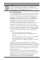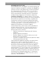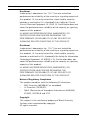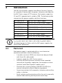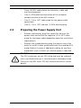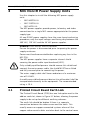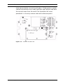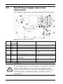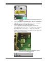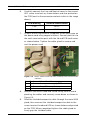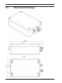
1
MIC Series Power Supplies
MIC Series
en
Installation Manual
MIC Series Power Supplies
Table of Contents | en
3
Table of Contents
1
Safety
4
1.1
Important safety instructions
4
1.2
Safety precautions
6
1.3
Important notices
1.4
Customer Support and Service
14
7
2
Introduction
16
2.1
Parts List
16
2.2
Preparing the Power Supply Unit
17
2.3
Securing the Power Supply Unit
18
2.4
IP Rating
18
2.5
MIC Shielded Composite Cable Gland Connection
19
3
MIC Non-IR Power Supply Units
20
3.1
Printed Circuit Board Earth Link
20
3.2
Non-IR Power Supply Layout and Connections
22
3.3
Fuse Ratings
23
3.4
Installing a Non-IR Power Supply
24
3.5
Optional Cards and Kits for Non-IR MIC Cameras
29
3.6
Commissioning a MIC Series Camera with Public Address
Speakers
29
3.7
Commissioning a MIC Series Camera with Heater Option
30
4
MIC IR Power Supply Units
32
4.1
Printed Circuit Board Earth Link
33
4.2
Fuse Ratings
34
4.3
MIC IR Power Supply Layout and Connections
35
4.4
Installing a MIC IR Power Supply
36
4.5
Commissioning the IR Lamps
42
5
Technical Specifications
43
5.1
Dimensional Drawings
44
Bosch Security Systems, Inc.
Installation Manual
F.01U.141.598 | 1.0 | 2009.11
4
en | Safety
MIC Series Power Supplies
1
Safety
1.1
Important safety instructions
Read, follow, and retain for future reference all of the following
safety instructions. Heed all warnings on the unit and in the
operating instructions before operating the unit.
1.
Cleaning - Unplug the unit from the outlet before cleaning.
Follow any instructions provided with the unit. Generally,
using a dry cloth for cleaning is sufficient, but a moist flufffree cloth or leather shammy may also be used. Do not use
liquid cleaners or aerosol cleaners.
2.
Heat Sources - Do not install the unit near any heat
sources such as radiators, heaters, stoves, or other
equipment (including amplifiers) that produce heat.
3.
Water - Do not use this unit near a bathtub, washbowl, or a
sink.
4.
Object and liquid entry - Never push objects of any kind
into this unit through openings as they may touch
dangerous voltage points or short-out parts that could
result in a fire or electrical shock. Never spill liquid of any
kind in the unit. Do not place objects filled with liquids,
such as vases or cups, on the unit.
5.
Lightning - For added protection during a lightning storm,
or when leaving this unit unattended and unused for long
periods, unplug the unit from the wall outlet and
disconnect the cable system. This will prevent damage to
the unit from lightning and power line surges.
6.
Controls adjustment - Adjust only those controls specified
in the operating instructions. Improper adjustment of
other controls may cause damage to the unit. Use of
controls or adjustments, or performance of procedures
other than those specified, may result in hazardous
radiation exposure.
7.
Overloading - Do not overload outlets and extension cords.
This can cause fire or electrical shock.
F.01U.141.598 | 1.0 | 2009.11
Installation Manual
Bosch Security Systems, Inc.
MIC Series Power Supplies
8.
Safety | en
5
Power supply cord and plug protection - Protect the
power supply cord and plug from foot traffic, being
pinched by items placed upon or against them at electrical
outlets, and its exit from the unit. For units intended to
operate with 230 VAC, 50 Hz, the power supply cord must
comply with the latest versions of IEC 60227. For units
intended to operate with 120 VAC, 60 Hz, the power
supply cord must comply with the latest versions of UL 62
and CSA 22.2 No.49.
9.
Power disconnect - Units have power supplied to the unit
whenever the power cord is inserted into the power
source. The power cord is the main power disconnect
device for switching off the voltage for all units.
10. Servicing - Do not attempt to service this unit yourself.
Opening or removing covers may expose you to dangerous
voltage or other hazards. Refer all servicing to qualified
service personnel.
11. Damage requiring service - Unplug the unit from the main
AC power source and refer servicing to qualified service
personnel when any damage to the equipment has
occurred, such as:
–
the power supply cord or plug is damaged;
–
exposure to moisture, water, and/or inclement
weather (rain, snow, etc.);
–
liquid has been spilled in or on the equipment;
–
an object has fallen into the unit;
–
unit has been dropped or the unit cabinet is damaged;
–
unit exhibits a distinct change in performance;
–
unit does not operate normally when the user
correctly follows the operating instructions.
12. Replacement parts - Be sure the service technician uses
replacement parts specified by the manufacturer, or that
have the same characteristics as the original parts.
Unauthorized substitutions may cause fire, electrical
shock, or other hazards.
Bosch Security Systems, Inc.
Installation Manual
F.01U.141.598 | 1.0 | 2009.11
6
en | Safety
MIC Series Power Supplies
13. Safety check - Safety checks should be performed upon
completion of service or repairs to the unit to ensure
proper operating condition.
14. Installation - Install in accordance with the manufacturer's
instructions and in accordance with applicable local codes.
15. Attachments, changes or modifications - Only use
attachments/accessories specified by the manufacturer.
Any change or modification of the equipment, not
expressly approved by Bosch, could void the warranty or,
in the case of an authorization agreement, authority to
operate the equipment.
1.2
Safety precautions
DANGER!
High risk: This symbol indicates an imminently hazardous
situation such as “Dangerous Voltage” inside the product.
This symbol indicates the presence of non-insulated
“dangerous voltage” within the product’s enclosure that may be
of sufficient magnitude to constitute a risk of electric shock to
persons.
WARNING!
Medium risk: Indicates a potentially hazardous situation.
If not avoided, this could result in minor or moderate bodily
injury.
CAUTION!
Low risk: Indicates a potentially hazardous situation.
If not avoided, this could result in property damage or risk of
damage to the unit.
F.01U.141.598 | 1.0 | 2009.11
Installation Manual
Bosch Security Systems, Inc.
MIC Series Power Supplies
1.3
Safety | en
7
Important notices
Accessories - Do not place this unit on an unstable stand,
tripod, bracket, or mount. The unit may fall, causing serious
injury and/or serious damage to the unit. Use only with the
cart, stand, tripod, bracket, or table specified by the
manufacturer. When a cart is used, use caution and care
when moving the cart/apparatus combination to avoid injury
from tip-over. Quick stops, excessive force, or uneven
surfaces may cause the cart/unit combination to overturn.
Mount the unit per the manufacturer's instructions.
All-pole power switch - Incorporate an all-pole power switch,
with a contact separation of at least 3 mm in each pole, into the
electrical installation of the building.If it is needed to open the
housing for servicing and/or other activities, use this all-pole
switch as the main disconnect device for switching off the
voltage to the unit.
Coax grounding:
–
Ground the cable system if connecting an outside cable
system to the unit.
–
Connect outdoor equipment to the unit's inputs only after
this unit has had its grounding plug connected to a
grounded outlet or its ground terminal is properly
connected to a ground source.
–
Disconnect the unit's input connectors from outdoor
equipment before disconnecting the grounding plug or
grounding terminal.
–
Follow proper safety precautions such as grounding for
any outdoor device connected to this unit.
U.S.A. models only - Section 810 of the National Electrical Code,
ANSI/NFPA No.70, provides information regarding proper
grounding of the mount and supporting structure, grounding of
the coax to a discharge unit, size of grounding conductors,
location of discharge unit, connection to grounding electrodes,
and requirements for the grounding electrode.
Bosch Security Systems, Inc.
Installation Manual
F.01U.141.598 | 1.0 | 2009.11
8
en | Safety
MIC Series Power Supplies
Disposal - Your Bosch product was developed and manufactured
with high-quality material and components that can be recycled
and reused. This symbol means that electronic and electrical
appliances, which have reached the end of their working life, must
be collected and disposed of separately from household waste
material. Separate collecting systems are usually in place for
disused electronic and electrical products. Please dispose of these
units at an environmentally compatible recycling facility, per
European Directive 2002/96/EC.
Environmental statement - Bosch has a strong commitment
towards the environment. This unit has been designed to
respect the environment as much as possible.
Electrostatic-sensitive device - Use proper CMOS/MOS-FET
handling precautions to avoid electrostatic discharge.
NOTE: Wear required grounded wrist straps and observe proper
ESD safety precautions when handling the electrostaticsensitive printed circuit boards.
Fuse rating - For security protection of the device, the branch
circuit protection must be secured with a maximum fuse rating
of 16A. This must be in accordance with NEC800 (CEC Section
60).
Grounding and polarization - This unit may be equipped with a
polarized alternating current line plug (a plug with one blade
wider than the other blade). This safety feature allows the plug
to fit into the power outlet in only one way. If unable to insert
the plug fully into the outlet, contact a locally certified
electrician to replace the obsolete outlet. Do not defeat the
safety purpose of the polarized plug.
Alternately, this unit may be equipped with a 3-pole grounding
plug (a plug with a third pin for earth grounding). This safety
feature allows the plug to fit into a grounded power outlet only.
If unable to insert the plug into the outlet, contact a locally
certified electrician to replace the obsolete outlet. Do not
defeat the safety purpose of the grounding plug.
F.01U.141.598 | 1.0 | 2009.11
Installation Manual
Bosch Security Systems, Inc.
MIC Series Power Supplies
Safety | en
9
Moving - Disconnect the power before moving the unit. Move
the unit with care. Excessive force or shock may damage the
unit and the hard disk drives.
Outdoor signals - The installation for outdoor signals, especially
regarding clearance from power and lightning conductors and
transient protection, must be in accordance with NEC725 and
NEC800 (CEC Rule 16-224 and CEC Section 60).
Permanently connected equipment - Incorporate a readily
accessible disconnect device in the building installation wiring.
Pluggable equipment - Install the socket outlet near the
equipment so it is easily accessible.
Power resupply - If the unit is forced to power down due to
exceeding the specified operating temperatures, disconnect
the power cord, wait for at least 30 seconds, and then
reconnect the power cord.
Power lines - Do not locate the camera near overhead power
lines, power circuits, or electrical lights, nor where it may
contact such power lines, circuits, or lights.
Rack-mount
–
Ventilation - Do not place this unit in a built-in installation
or rack without proper ventilation or adhering to the
manufacturer's instructions. The equipment must not
exceed its maximum operating temperature requirements.
–
Mechanical loading - Properly mount the equipment in a
rack to prevent a hazardous condition due to uneven
mechanical loading.
CAUTION!
Connecting System ground to Safety ground may result in
ground loops that can disrupt the CCTV system.
Video loss - Video loss is inherent to digital video recording;
therefore, Bosch Security Systems cannot be held liable for any
damage that results from missing video information. To
minimize the risk of lost digital information, Bosch Security
Systems recommends multiple, redundant recording systems,
and a procedure to back up all analog and digital information.
Bosch Security Systems, Inc.
Installation Manual
F.01U.141.598 | 1.0 | 2009.11
10
en | Safety
MIC Series Power Supplies
NOTICE!
This is a class B product. In a domestic environment this
product may cause radio interference, in which case the user
may be required to take adequate measures.
FCC & ICES Information
This equipment has been tested and found to comply with the
limits for a Class B digital device, pursuant to part 15 of the
FCC Rules. These limits are designed to provide reasonable
protection against harmful interference in a residential
installation. This equipment generates, uses, and can radiate
radio frequency energy and, if not installed and used in
accordance with the instructions, may cause harmful
interference to radio communications. However, there is no
guarantee that interference will not occur in a particular
installation. If this equipment does cause harmful interference
to radio or television reception, which can be determined by
turning the equipment off and on, the user is encouraged to try
to correct the interference by one or more of the following
measures:
–
reorient or relocate the receiving antenna;
–
increase the separation between the equipment and
receiver;
–
connect the equipment into an outlet on a circuit different
from that to which the receiver is connected;
–
consult the dealer or an experienced radio/TV technician
for help.
Intentional or unintentional modifications, not expressly
approved by the party responsible for compliance, shall not be
made. Any such modifications could void the user's authority to
operate the equipment. If necessary, the user should consult
the dealer or an experienced radio/television technician for
corrective action.
The user may find the following booklet, prepared by the
Federal Communications Commission, helpful: How to Identify
and Resolve Radio-TV Interference Problems. This booklet is
available from the U.S. Government Printing Office,
Washington, DC 20402, Stock No. 004-000-00345-4.
F.01U.141.598 | 1.0 | 2009.11
Installation Manual
Bosch Security Systems, Inc.
MIC Series Power Supplies
Safety | en
11
INFORMATIONS FCC ET ICES
Suite à différents tests, cet appareil s'est révélé conforme aux
exigences imposées aux appareils numériques de classe B, en
vertu de la section 15 du règlement de la Commission fédérale
des communications des États-Unis (FCC), et en vertu de la
norme ICES-003 d'Industrie Canada. Ces exigences visent à
fournir une protection raisonnable contre les interférences
nuisibles lorsque l'appareil est utilisé dans le cadre d'une
installation résidentielle. Cet appareil génère, utilise et émet
de l'énergie de radiofréquences et peut, en cas d'installation ou
d'utilisation non conforme aux instructions, engendrer des
interférences nuisibles au niveau des radiocommunications.
Toutefois, rien ne garantit l'absence d'interférences dans une
installation particulière. Il est possible de déterminer la
production d'interférences en mettant l'appareil
successivement hors et sous tension, tout en contrôlant la
réception radio ou télévision. L'utilisateur peut parvenir à
éliminer les interférences éventuelles en prenant une ou
plusieurs des mesures suivantes:
–
Modifier l'orientation ou l'emplacement de l'antenne
réceptrice;
–
Éloigner l'appareil du récepteur;
–
Brancher l'appareil sur une prise située sur un circuit
–
Consulter le revendeur ou un technicien qualifié en radio/
différent de celui du récepteur;
télévision pour obtenir de l'aide.
Toute modification apportée au produit, non expressément
approuvée par la partie responsable de l'appareil, est
strictement interdite. Une telle modification est susceptible
d'entraîner la révocation du droit d'utilisation de l'appareil.
La brochure suivante, publiée par la Commission fédérale des
communications (FCC), peut s'avérer utile : How to Identify and
Resolve Radio-TV Interference Problems (Comment identifier et
résoudre les problèmes d’interférences de radio et de télévision).
Cette brochure est disponible auprès du U.S. Government
Printing Office, Washington, DC 20402, États-Unis, sous la
référence n° 004-000-00345-4.
Bosch Security Systems, Inc.
Installation Manual
F.01U.141.598 | 1.0 | 2009.11
12
en | Safety
MIC Series Power Supplies
Disclaimer
Underwriter Laboratories Inc. (“UL”) has not tested the
performance or reliability of the security or signaling aspects of
this product. UL has only tested fire, shock and/or casualty
hazards as outlined in UL's Standard(s) for Safety for Closed
Circuit Television Equipment, UL 2044. UL Certification does not
cover the performance or reliability of the security or signaling
aspects of this product.
UL MAKES NO REPRESENTATIONS, WARRANTIES, OR
CERTIFICATIONS WHATSOEVER REGARDING THE
PERFORMANCE OR RELIABILITY OF ANY SECURITY OR
SIGNALING RELATED FUNCTIONS OF THIS PRODUCT.
Disclaimer
Underwriter Laboratories Inc. (“UL”) has not tested the
performance or reliability of the security or signaling aspects of
this product. UL has only tested fire, shock and/or casualty
hazards as outlined in UL's Standard(s) for Safety for Information
Technology Equipment, UL 60950-1. UL Certification does not
cover the performance or reliability of the security or signaling
aspects of this product.
UL MAKES NO REPRESENTATIONS, WARRANTIES, OR
CERTIFICATIONS WHATSOEVER REGARDING THE
PERFORMANCE OR RELIABILITY OF ANY SECURITY OR
SIGNALING-RELATED FUNCTIONS OF THIS PRODUCT.
Notice of Regulatory Compliance
This product complies with the following EC directives:
–
EMC Directive (89/336/EC as amended)
–
LV Directive (73/23/EC)
–
RoHS (Restriction of Hazardous Substances) 2002/95/
ECEMC, CISPRA-B and CTIC
Copyright
This manual is the intellectual property of Bosch Security
Systems and is protected by copyright.
All rights reserved.
F.01U.141.598 | 1.0 | 2009.11
Installation Manual
Bosch Security Systems, Inc.
MIC Series Power Supplies
Safety | en
13
Trademarks
All hardware and software product names used in this
document are likely to be registered trademarks and must be
treated accordingly.
NOTE!
This manual has been compiled with great care and the
information it contains has been thoroughly verified. The text
was complete and correct at the time of printing. The ongoing
development of the products may mean that the content of the
user guide can change without notice. Bosch Security Systems
accepts no liability for damage resulting directly or indirectly
from faults, incompleteness or discrepancies between the user
guide and the product described.
More information
For additional information, please contact the Bosch Security
Systems location nearest you or visit our web site at
www.boschsecurity.com
Bosch Security Systems, Inc.
Installation Manual
F.01U.141.598 | 1.0 | 2009.11
14
en | Safety
1.4
MIC Series Power Supplies
Customer Support and Service
If this unit needs service, contact the nearest Bosch Security
Systems Service Center for authorization to return and shipping
instructions.
Service Centers
USA
Repair CenterTelephone: 800-566-2283
Fax: 800-366-1329
E-mail: [email protected]
Customer Service
Telephone: 888-289-0096
Fax: 585-223-9180
E-mail: [email protected]
Technical Support
Telephone: 800-326-1450
Fax: 585-223-3508 or 717-735-6560
E-mail: [email protected]
Canada
Telephone: 514-738-2434
Fax: 514-738-8480
Europe, Middle East, Africa Region
Repair Center
Telephone: 31 (0) 76-5721500
Fax: 31 (0) 76-5721413
E-mail: [email protected]
Asia Region
Repair Center
Telephone: 65 63522776
Fax: 65 63521776
E-mail: [email protected]
Customer Service
Telephone: 86 (0) 756 7633117 or
86 (0) 756 7633121
Fax: 86 (0) 756 7631710
E-mail: [email protected]
F.01U.141.598 | 1.0 | 2009.11
Installation Manual
Bosch Security Systems, Inc.
MIC Series Power Supplies
Safety | en
15
Warranty and more information
For additional information and warranty queries, please contact
your Bosch Security Systems representative or visit our website
at www.boschsecurity.com.
Bosch Security Systems, Inc.
Installation Manual
F.01U.141.598 | 1.0 | 2009.11
16
en | Introduction
2
MIC Series Power Supplies
Introduction
The MIC Series power supplies from Bosch Security Systems,
Inc. provide all connections for power, telemetry and video for
the MIC Series range of PTZ cameras. Each power supply has
CE and FCC approval and is rated to IP65. The following table
summarizes the power supplies and their functions:
MIC-240PSU-UL
240 VAC MIC Power Supply
MIC-IR-240PSU-UL
240 VAC MIC IR only Power Supply
MIC-115PSU-UL
115 VAC MIC Power Supply
MIC-IR-115PSU-UL
115 VAC MIC IR only Power Supply
MIC-24PSU-UL
24 VAC MIC Power Supply
MIC-IR-24PSU-UL
24 VAC MIC IR only Power Supply
NOTICE!
Use the MIC-2M-S, MIC-10M-S, MIC-20M-S and MIC-25M-S
Shielded Composite Cables with the MIC power supplies for
correct EMC protection.
2.1
Parts List
Each power supply is contained within a cast aluminium
enclosure and comes with the following:
–
A weather resistant (IP65) cast aluminium box pre-fitted
with three (3) cable glands.
–
A power supply for a MIC Series camera.
–
Provision for driving various interface cards mounted
internally to the power supply box, for example an alarm
interface card (Non-IR power supplies only).
–
Provision for a signal interface card (BP-3 or BP-4) to
connect telemetry to Bosch Biphase equipment.
–
Screw termination of all composite, telemetry and ancillary
cables in the box.
–
Earth isolation and termination within the unit to correctly
control video earthing and to prevent earth loop.
F.01U.141.598 | 1.0 | 2009.11
Installation Manual
Bosch Security Systems, Inc.
MIC Series Power Supplies
–
Introduction | en
17
Three (3) M12 cable glands for telemetry, video and
ancillary equipment.
–
One (1) M16 gland for connection of the screened
composite cable to the MIC camera.
–
One (1) 1/2 in. NPT cable gland for the power cable
–
One (1) 1/2 in. NPT and one (1) M12 blanking plug.
connection.
2.2
Preparing the Power Supply Unit
–
Remove the blanking plug that covers the hole for the
power cable and attach the supplied 1/2 in. NPT cable
gland for the power cable depending upon the installation
requirements.
–
Remove the second blanking plug that covers one of the
holes for an M12 cable gland and attach the supplied M12
gland fitted in its place if additional cabling for ancillary
equipment such as alarms or a washer pump is required.
CAUTION!
The PSU enclosures are not EXD rated and must be replaced
with a certified enclosure if installed within a hazardous area.
Please see the MIC Series EXD 440 Camera manual for further
details.
Bosch Security Systems, Inc.
Installation Manual
F.01U.141.598 | 1.0 | 2009.11
18
en | Introduction
2.3
MIC Series Power Supplies
Securing the Power Supply Unit
Secure the power supply unit using four (4) M6 screws or bolts
(not supplied); which secure through the holes in the enclosure
as shown In the figure below.
Figure 2.1
1
2
2.4
Enclosure mounting and enclosure lid screw holes
Enclosure mounting screw
Enclosure lid screw hole
IP Rating
The power supply enclosure is an IP65 weather-resistant cast
aluminium enclosure. To maintain the environmental rating of
this enclosure, install only listed or recognized conduit hubs or
fittings with the same environmental rating as the enclosure in
compliance with the installation instruction of the hub or
fitting.
F.01U.141.598 | 1.0 | 2009.11
Installation Manual
Bosch Security Systems, Inc.
MIC Series Power Supplies
2.5
Introduction | en
19
MIC Shielded Composite Cable Gland
Connection
The MIC power supplies are designed to use the MIC shielded
composite cable. Fit this cable into the M16 nickel plated brass
cable gland as detailed below. It is important that the braided
cable screen engages with the internal clamps of the cable
gland to ensure correct EMC protection.
1.
Strip the cable jacket back, leaving 25 mm of braided
shield; then fold the braided shield back over the cable
jacket.
2.
Insert the shielded composite cable into the cable gland
until the braided shield reaches the internal clamp position
(approximately 20 mm inside gland)
3.
Tighten the dome nut with a wrench to ensure the nut is
fully tightened and securely grips the cable and braided
shield as shown below.
Figure 2.2 Composite cable gland connection
Bosch Security Systems, Inc.
Installation Manual
F.01U.141.598 | 1.0 | 2009.11
20
en | MIC Non-IR Power Supply Units
3
MIC Series Power Supplies
MIC Non-IR Power Supply Units
Use this chapter to install the following MIC power supply
units:
–
MIC-240PSU-UL
–
MIC-115PSU-UL
–
MIC-24PSU-UL
The MIC power supplies provide power, telemetry and video
connections for a single MIC camera appropriate for the power
supply type.
All non-IR MIC power supplies have the same layout and wiring
procedure; only the input voltages and fusing vary between the
230 VAC, 115 VAC and the 24 VAC power supplies.
DANGER! ELECTRICAL SHOCK HAZARD
Ensure the power is disconnected prior to opening the power
supply enclosure.
Power must be disconnected before replacing any fuse in the
MIC PSU.
The MIC power supplies have a separate internal shield
covering the power cable input head-end (HD1).
Only suitably qualified persons should remove this shield and
connect the mains power cable, the shield MUST be re-fitted
and fully secured prior to connecting the power.
The mains supply cable shall have conductors of a maximum
size of 12 AWG.
A readily accessible disconnect device (circuit breaker) shall be
incorporated externally to the equipment. The recommended
rating is 15 A.
3.1
Printed Circuit Board Earth Link
The Printed Circuit Board (PCB) has one link option next to the
add-on card slot, shown in Figure 3.1 below, allowing the power
supply to be set up for different earthing schemes.
The earth link should be broken if there is a separate
connection between the video screen and the earth. This
usually occurs on copper connected systems where all the
copper video coaxial cables are taken back to the control room
F.01U.141.598 | 1.0 | 2009.11
Installation Manual
Bosch Security Systems, Inc.
MIC Series Power Supplies
MIC Non-IR Power Supply Units | en
21
to be connected to a central earth point. If fiber optics or other
indirect connections are used to get data and video to and from
the control room then the earth link should be left intact
provided it is the only camera end earth reference point.
Figure 3.1
Bosch Security Systems, Inc.
Position of earth link
Installation Manual
F.01U.141.598 | 1.0 | 2009.11
22
en | MIC Non-IR Power Supply Units
3.2
MIC Series Power Supplies
Non-IR Power Supply Layout and
Connections
The following figure shows the power supply PCB connections:
Figure 3.2
MIC-240PSU-UL layout
Item
PSU
Head-end Description
Head-end Terminal
1
2
3
4
Head-end
HD1
HD2
HD3
HD4 and
Power cable head-end
Tamper switch head-end
Composite cable head-end
Telemetry head-ends
Screw terminal
Screw terminal
Screw terminal
Screw terminal or Molex
5
6
HD5
HD6
HD8
Heater head-end
Optional 516 Kbd power
crimp
Screw terminal
Molex crimp
7
8
CN1
CN2/3
head-end
Coax Video head-end
Auxiliary card head-end
BNC crimp
Plug in
CAUTION!
Do not Connect MIC PA or MIC IR units to a MIC-PSU with the
heater option enabled as this can result in damage to the
cameras. Ensure that the heater link is disabled if a MIC PA is
used and ensure an IR power supply is used with a MIC IR
camera unit.
F.01U.141.598 | 1.0 | 2009.11
Installation Manual
Bosch Security Systems, Inc.
MIC Series Power Supplies
3.3
MIC Non-IR Power Supply Units | en
23
Fuse Ratings
CAUTION!
Replace with only the same type and rating of the fuse for
continued protection against the risk of fire, damage or injury.
The power supply houses four (4) off 20 mm fuses in fuse
holders. The ratings for these fuses are fixed on the low voltage
secondary side but changes with the input voltage on the high
voltage primary side.
The following table shows the fuse values that should be fitted
to provide proper protection for the MIC-240PSU-UL, MIC115PSU-UL and the MIC-24PSU-UL Non-IR power supplies.
Note: Fuse FS4 does not exist.
Fuse
Function
Ratings for
Ratings for
Ratings for
240 V Primary 115 V Primary 24 V Primary
1.6 A glass
1.6 A glass
1.6 A glass
FS1
MIC protection
FS2
Primary protection
anti-surge (T)
500 mA quick
FS3
Heater protection 1
blow
1.6 A glass
FS5
Heater protection 2
anti-surge (T)
1.6 A glass
anti-surge (T) anti-surge (T)
1.6 A glass
1.6 A glass
anti-surge (T)
anti-surge (T) anti-surge (T)
anti-surge (T) anti-surge (T)
800 mA quick 2.5 A ceramic
blow
1.6 A glass
quick blow
1.6 A glass
WARNING!
Fitting fuses other than the values described above invalidates
the product warranty and may result in damage to the product
or injury to the installer.
Bosch Security Systems, Inc.
Installation Manual
F.01U.141.598 | 1.0 | 2009.11
24
en | MIC Non-IR Power Supply Units
3.4
MIC Series Power Supplies
Installing a Non-IR Power Supply
DANGER! ELECTRICAL SHOCK HAZARD
Ensure the power is disconnected prior to opening the power
supply enclosure.
Power must be disconnected before replacing any fuse in the
MIC PSU.
The MIC power supplies have a separate internal shield
covering the power cable input head-end (HD1).
Only suitably qualified persons should remove this shield and
connect the mains power cable, the shield MUST be re-fitted
and fully secured prior to connecting the power.
The mains supply cable shall have conductors of a maximum
size of 12 AWG.
A readily accessible disconnect device (circuit breaker) shall be
incorporated externally to the equipment. The recommended
rating is 15 A.
1.
Locate the mounting position of the MIC-PSU so that it
cannot be interfered with either intentionally or
accidentally, a lockable cabinet is recommended.
2.
Securely fix the power supply enclosure using M6 screws
(not supplied); ensure the cable glands have sufficient
room to allow for the cables to enter approximately 60 mm
on either side of the enclosure.
3.
Open the power supply enclosure and undo the M3 screws
on the internal shield and retain these; then remove the
internal shield covering the mains cable head-end HD1.
Removing this shield also gives access to the blanking plug
to allow a suitable conduit or the cable gland to be fitted.
F.01U.141.598 | 1.0 | 2009.11
Installation Manual
Bosch Security Systems, Inc.
MIC Series Power Supplies
MIC Non-IR Power Supply Units | en
25
Figure 3.3 High voltage input head-end shield fitted inside the PSU
enclosure
4.
If using a conduit for the power cord, remove the blanking
plug and install a suitable conduit in its place. Secure as
recommended by the conduit manufacturer.
5.
If using a power cord without a conduit, remove the
blanking plug and fit the 1/2-in. NPT cable gland instead as
depicted below. Please note it is easier to fit the cord
through the gland outside of the enclosure then attach the
cable gland to the enclosure.
Figure 3.4 Mains input head-end with shield removed showing
HD1 terminal and cable gland fitted
1
2
3
Bosch Security Systems, Inc.
Earth core to power supply PCB
Earth core to enclosure lid
Earth post
Installation Manual
F.01U.141.598 | 1.0 | 2009.11
26
en | MIC Non-IR Power Supply Units
6.
MIC Series Power Supplies
Carefully connect the Live and Neutral cores to the correct
HD1 screw terminals as shown below and also printed on
the PCB (next to the connector and not visible in the image
above).
7.
PCB Marking
Terminal Identification
Live
HD1-L
Neutral
HD1-N
Crimp a 6 mm ring terminal (supplied) to the earth core on
the power cord using copper washers. Securely bolt this to
the earth termination post with the lid and PCB earth wires
as shown below. Tighten the cable gland to secure and
seal the power cord.
Figure 3.5
1
2
3
4
8.
Mains cable wired into HD1 showing earth terminal connections
Enclosure lid earth cable
Earth core from power supply PCB
Earth core from Mains cord
Enclosure earth termination post
Reattach the mains head-end shield taking care to avoid
pinching the cables and securely screw down as shown in
Figure 3.3.
9.
Feed the shielded composite cable through the metal M16
gland; then connect the shielded composite cable to the
screw terminal head-end HD3 as shown below and printed
on the PCB. When completed tighten the cable gland to
firmly grip the shielded cable.
F.01U.141.598 | 1.0 | 2009.11
Installation Manual
Bosch Security Systems, Inc.
MIC Series Power Supplies
Composite Cable
Wire Color
Red
Green
White
Yellow
Drain Wire
Blue
Violet
Coax Core
Coax Screen
Black (optional)
Orange (optional)
MIC Non-IR Power Supply Units | en
27
Function
MIC PSU
PCB Marking
AC supply
AC supply return
RX +
Rx Ground
Tx Tx +
Video
Video return
Tamper switch
Wash drive
Terminal Block
HD3-1
HD3-2
HD3-3
HD3-4
HD3-5
HD3-6
HD3-7
HD3-8
HD3-9
HD3-10
HD3-11
Power
Power
RxB
RxA
GND
TxA
TxB
Video
Vid 0V
Tamp Sw
Wash
NOTICE!
The earth core 6 mm ring crimp should be a Tyco Electronics, 00321045-0, PIDG, M6, BLUE, UL certification CCN ZMVV, file
E13288. A suitable ring crimp tool for fitting the ring crimp is a
Davico type DHCR15 or equivalents.
Figure 3.6 Shielded composite cable connected to HD3
Bosch Security Systems, Inc.
Installation Manual
F.01U.141.598 | 1.0 | 2009.11
28
en | MIC Non-IR Power Supply Units
MIC Series Power Supplies
10. Connect a tamper switch relay to HD2, if necessary.
11. Feed the coax cable through the cable gland and crimp the
end with a BNC connector then connect the coax video
cable to the CN1 head-end.
Figure 3.7
Coaxial video connection
12. Use CN2 for additional add-on cards such as the 8-input
alarm card or the Biphase card.
13. Crimp or screw telemetry connections to head-ends HD4
and HD5 to connect the MIC camera to the control room as
shown below.
Telemetry Signal Name
RxB or Rx RxA or Rx +
GND
TxA or Tx TxB or Tx +
Figure 3.8
F.01U.141.598 | 1.0 | 2009.11
HD3
Pin 3
Pin 4
Pin 5
Pin 6
Pin 7
HD4
Pin 1
Pin 2
Pin 3
Pin 4
Pin 5
HD5
Pin 1
Pin 2
Pin 3
Pin 4
Pin 5
Telemetry connections from HD5
Installation Manual
Bosch Security Systems, Inc.
MIC Series Power Supplies
MIC Non-IR Power Supply Units | en
29
14. When wiring is complete, apply power and check the all
four (4) LEDs are lit.
–
LED1 – 18 VAC power on to camera
–
LED2 – 18 VAC power on to camera
–
LED4 – Power on for optional heater
–
LED5 – Power on for optional heater
15. Re-attach the enclosure lid and screw it down until tight.
16. For installation of the MIC-WKT-KIT, MIC-ALM or MIC-BP-4
Biphase card please refer to the respective manuals.
3.5
Optional Cards and Kits for Non-IR MIC
Cameras
The MIC power supplies have several optional cards and kits.
Please refer to the respective manuals for details on their
installation and operation.
MIC-WKT
Washer bracket, nozzle and pump card kit for non-
MIC-ALM
IR cameras.
8-input alarm card for non-IR cameras, includes
MIC-BP3
washer pump drive function.
Bosch Biphase converter card for MIC-power
supplies without an expansion slot available
MIC-BP4
including all IR power supplies.
Bosch Biphase converter card for MIC power
supplies with an available expansion slot.
3.6
Commissioning a MIC Series Camera with
Public Address Speakers
The MIC Series Public Address camera has two (2) 6 W, 8 Ohm,
IP67 rated speakers connected in series to allow for public
address (PA) applications. These use the brown and gray wires
on the composite cable that are normally used for IR
illuminators or heaters.
There is no connection terminal for speakers on the power
supply itself; connect the speakers directly to a third party
amplifier and microphone using a chock block (not supplied).
To use the speakers please do the following:
Bosch Security Systems, Inc.
Installation Manual
F.01U.141.598 | 1.0 | 2009.11
30
en | MIC Non-IR Power Supply Units
1.
MIC Series Power Supplies
Disconnect the power supply from the power source;
locate the brown and gray wires in the shielded composite
cable.
2.
Using a terminal block (not supplied) connect the brown
and gray wires from the speakers.
3.
Feed the speaker cable through one of the conduit glands
in the power supply unit enclosure.
4.
Connect the speaker cable from a third party amplifier and
microphone.
3.7
Commissioning a MIC Series Camera with
Heater Option
These instructions are applicable to the MIC non-IR power
supplies only.
There are two links on the power supply printed circuit board
which must be changed to allow heater operation.
Please do the following to enable the heaters to function:
1.
Disconnect the power supply from the power source.
2.
Locate the PCB links next to HD6 (item 1, below), the
default setting is 0 V.
Figure 3.9
F.01U.141.598 | 1.0 | 2009.11
Heater link set to 0 V (default)
Installation Manual
Bosch Security Systems, Inc.
MIC Series Power Supplies
3.
4.
MIC Non-IR Power Supply Units | en
31
Break the two wire links and remove any excess solder.
Solder the wire links using a soldering iron and TCW link
wire from the left hand pads to the middle pads.
Figure 3.10
5.
Heater link set to +18 V
The power supply will now deliver +18 VAC to head-end
HD6.
Composite Cable
Function
MIC PSU Terminal Block
Wire Color
Brown
Heater1 or
HD6-1
IR Lamps2
Gray
Heater1 or
HD6-2
IR Lamps2
1. See Section 3.7 Commissioning a MIC Series Camera with Heater
Option, page 30, for details on commissioning MIC cameras with the
heater option fitted.
2. IR power supplies only; see Section 4 MIC IR Power Supply Units,
page 32, for more details.
6.
Connect the heater wires (brown and gray) from the
shielded composite cable to the HD6 termination head-end
as labelled on the PCB.
7.
The heaters are thermostatically controlled and will
automatically turn on at +5°C (+41°F) and turn off at +15°C
(+59°F).
8.
Check all connections, reseal the PSU enclosure and
reapply power.
Bosch Security Systems, Inc.
Installation Manual
F.01U.141.598 | 1.0 | 2009.11
32
4
en | MIC IR Power Supply Units
MIC Series Power Supplies
MIC IR Power Supply Units
Use this chapter to install the following MIC power supply
units:
–
MIC-IR-240PSU-UL
–
MIC-IR-115PSU-UL
–
MIC-IR-24PSU-UL
The power supplies for the MIC Series IR cameras are available
in 230/115 VAC source and 24 VAC source versions.
DANGER! ELECTRICAL SHOCK HAZARD
Ensure the power is disconnected prior to opening the power
supply enclosure.
Power must be disconnected before replacing any fuse in the
MIC PSU.
The MIC power supplies have a separate internal shield
covering the power cable input head-end (HD1).
Only suitably qualified persons should remove this shield and
connect the mains power cable, the shield MUST be re-fitted
and fully secured prior to connecting the power.
The mains supply cable shall have conductors of a maximum
size of 12 AWG.
A readily accessible disconnect device (circuit breaker) shall be
incorporated externally to the equipment. The recommended
rating is 15 A.
These power supplies have a second isolated power supply for
driving the IR illuminators. The operation of this power supply is
controlled by the camera itself via telemetry commands
received from the control room. The power supply operates the
twin illuminators using a constant current drive which
automatically configures itself for IR lamp operation. There are
no adjustable items within the power supply except for the
earth link discussed below.
The power supply also provides a circuit for operating a 24 VAC
or VDC washer pump and has four (4) volt-free alarm contact
inputs which activate presets within the camera but always
notifies the control system of the status of these alarms. The
F.01U.141.598 | 1.0 | 2009.11
Installation Manual
Bosch Security Systems, Inc.
MIC Series Power Supplies
MIC IR Power Supply Units | en
33
HD2 head-end provides the option for connection up to four (4)
alarm inputs to the power supply. These can be tamper
switches or inputs from other sensors or switches.
Earth isolation and termination within the unit provides correct
control of video earthing and thus prevents earth loops.
WARNING!
The washer pump relay is rated only to 24 VAC or VDC
maximum voltage and is not suitable for Mains operated
pumps.
4.1
Printed Circuit Board Earth Link
The Printed Circuit Board (PCB) has one link option just below
the Mains head-end cover plate, as shown below, allowing the
power supply to be set up for different earthing schemes.
Figure 4.1
IR PSU earth link
The earth link (item 1, above) should be broken if there is a
separate connection between the video screen and the earth.
This usually occurs on copper connected systems where all the
copper video coaxes are taken back to the control room to be
connected to a central earth point. If fiber optics or other
indirect connections are used to get data and video to and from
the control room then the earth link should be left intact
provided it is the only camera end earth reference point.
Bosch Security Systems, Inc.
Installation Manual
F.01U.141.598 | 1.0 | 2009.11
34
en | MIC IR Power Supply Units
4.2
MIC Series Power Supplies
Fuse Ratings
CAUTION!
Replace with only the same type and rating of the fuse for
continued protection against the risk of fire, damage or injury.
There are five (5) 20 mm fuses fitted to the power supply with
the following functions:
Fuse
Function
Type
Ratings for
Ratings for
240 V Primary 115 V Primary
FS1 18 VAC secondary
FS2
Glass
for transformer
IR lamp supply
FS4
fuse
Fuse for washer Ceramic
drive
FS5 18 VAC secondary
Glass
Glass
for 24 V
1.6 A quick
Primary
1.6 A quick
blow
1.0 A quick
blow
2.5 A quick
blow
2.5 A quick
blow
2.5 A quick
blow
2.5 A quick
blow
2.5 A quick
blow
2.5 A quick
blow
2.5 A quick
blow
1.6 A quick
blow
1.6 A quick
blow
1.6 A quick
blow
blow
blow
1.6 A quick
fuse. MIC supply
blow
Mains input fuse Ceramic 600 mA quick
FS3
Ratings
fuse. MIC supply
WARNING!
Fitting fuses other than the values described above invalidates
the product warranty and may result in damage to the product
or injury to the installer.
F.01U.141.598 | 1.0 | 2009.11
Installation Manual
Bosch Security Systems, Inc.
MIC Series Power Supplies
4.3
MIC IR Power Supply Units | en
35
MIC IR Power Supply Layout and
Connections
Figure 4.2
MIC-IR-240PSU layout
Item
PSU
Head-end Description
Head-end Terminal
1
2
3
4
Head-end
HD1
HD2
HD3
HD4 and
Power cable head-end
4-input alarm head-end
Composite cable head-end
Telemetry head-ends
Screw terminal
Screw terminal
Screw terminal
Screw terminal or Molex
5
6
7
HD5
HD6
HD7
CN1
IR lamps head-end
Washer drive head-end
Coax Video head-end
crimp
Screw terminal
Molex crimp
BNC crimp
Bosch Security Systems, Inc.
Installation Manual
F.01U.141.598 | 1.0 | 2009.11
36
en | MIC IR Power Supply Units
4.4
MIC Series Power Supplies
Installing a MIC IR Power Supply
DANGER! ELECTRICAL SHOCK HAZARD
Ensure the power is disconnected prior to opening the power
supply enclosure.
Power must be disconnected before replacing any fuse in the
MIC PSU.
The MIC power supplies have a separate internal shield
covering the power cable input head-end (HD1).
Only suitably qualified persons should remove this shield and
connect the mains power cable, the shield MUST be re-fitted
and fully secured prior to connecting the power.
The mains supply cable shall have conductors of a maximum
size of 12 AWG.
A readily accessible disconnect device (circuit breaker) shall be
incorporated externally to the equipment. The recommended
rating is 15 A.
To install the MIC-IR-240PSU, MIC-IR-115PSU and MIC-IR24PSU do the following:
1.
Locate the mounting position of the MIC-PSU so that it
cannot be interfered with either intentionally or
accidentally, a lockable cabinet is recommended.
2.
Securely fix the MIC-PSU using M6 screws and washers
(not supplied). Ensure the cable glands have sufficient
room, approximately 60 mm, to allow for the cables to
enter.
3.
Open the power supply enclosure and undo the M3 screws
on the internal shield and retain these; then remove the
internal shield covering the mains cable head-end HD1.
removing this shield also gives access to the blanking plug
to allow a suitable conduit or the cable gland to be fitted.
F.01U.141.598 | 1.0 | 2009.11
Installation Manual
Bosch Security Systems, Inc.
MIC Series Power Supplies
MIC IR Power Supply Units | en
37
Figure 4.3 High voltage input head-end shield fitted inside the PSU
enclosure
4.
If using a conduit for the power cord, remove the blanking
plug and install a suitable conduit in its place, secure as
recommended by the conduit manufacturer.
5.
If using a power cord without a conduit, remove the
blanking plug and fit the 1/2-in. NPT cable gland instead.
Note it is easier to fit the cable through the gland outside
of the enclosure then attach the cable gland to the
enclosure.
6.
Connect the power cord to HD1 carefully observing the
polarity as shown below.
7.
PCB Marking
Terminal Identification
Live
HD1-L
Neutral
HD1-N
Crimp a 6 mm ring terminal (supplied) to the earth core on
the power cord using copper washers. Securely bolt this to
the earth termination post with the Lid and PCB earth
wires as shown below. Tighten the cable gland to secure
and seal the power cable.
Bosch Security Systems, Inc.
Installation Manual
F.01U.141.598 | 1.0 | 2009.11
38
en | MIC IR Power Supply Units
Figure 4.4
1
2
3
4
8.
MIC Series Power Supplies
Mains cable wired into HD1 showing earth terminal connections
Enclosure lid earth cable
Earth core from power supply PCB
Earth core from Mains cable
Enclosure earth termination post
Feed the remaining video and telemetry cables through the
appropriate sized glands.
9.
Connect the composite cable to HD3 following the color
coding as shown below:
Composite Cable
Wire Color
Red
Green
White
Yellow
Drain Wire
Blue
Violet
Coax Core
Coax Screen
Black (optional)
Orange (optional)
F.01U.141.598 | 1.0 | 2009.11
Function
MIC PSU
PCB Marking
AC supply
AC supply return
RX +
Rx Ground
Tx Tx +
Video
Video return
Tamper switch
Wash drive
Terminal Block
HD3-1
HD3-2
Hd3-3
HD3-4
HD3-5
HD3-6
HD3-7
HD3-8
HD3-9
HD3-10
HD3-11
Power
Power
RxB
RxA
GND
TxA
TxB
Video
Vid 0V
Tamp Sw
Wash
Installation Manual
Bosch Security Systems, Inc.
MIC Series Power Supplies
MIC IR Power Supply Units | en
39
NOTICE!
The earth core 6 mm ring crimp should be a Tyco Electronics, 00321045-0, PIDG, M6, BLUE, UL certification CCN ZMVV, file
E13288. A suitable ring crimp tool for fitting the ring crimp is a
Davico type DHCR15 or equivalents.
10. Connect the brown and gray wires for the IR lamps to HD6.
Composite Cable Function
Wire Color
Brown
Gray
IR Lamp +
IR Lamp -
Terminal
PCB
head-end
HD6-1
HD6-2
Marking
IR+
IR-
11. Connect the coaxial video cable to the CN1 head-end.
Figure 4.5 Coaxial video connection
12. Connect alarm input cables to HD2, as shown below, if
necessary.
Connection
HD2 pin 1
HD2 pin 2
HD2 pin 3
HD2 pin 4
HD2 pin 5
HD2 pin 6
HD2 pin 7
HD2 pin 8
Bosch Security Systems, Inc.
Function
Alarm 1
0V
Alarm 2
0V
Alarm 3
0V
Alarm 4
0V
Installation Manual
F.01U.141.598 | 1.0 | 2009.11
40
en | MIC IR Power Supply Units
MIC Series Power Supplies
13. Crimp or screw telemetry connections to head-ends HD4
and HD5 to connect the MIC camera to the control room as
shown below.
Telemetry Signal Name
RxB or Rx RxA or Rx +
GND
TxA or Tx TxB or Tx +
HD3
Pin 3
Pin 4
Pin 5
Pin 6
Pin 7
HD4
Pin 1
Pin 2
Pin 3
Pin 4
Pin 5
HD5
Pin 1
Pin 2
Pin 3
Pin 4
Pin 5
14. A washer drive is provided as standard on the IR power
supplies. A 24 VAC rated relay is fitted via the on board
fuse F S4 (rated at 2 Amps). Connection to a third party
washer pump system should be made via HD7.
Signal
Washer Pump Live
Washer Pump Neutral
Connection
HD7 pin 1
HD 7 pin 2
PCB Marking
1
2
15. Test the washer by pressing the red SW1 button.
LED 3 illuminates in response to telemetry commands to
switch the washer on from the control room. Note that the
software in the camera prevents the washer from running
more than 10 seconds continuously to prevent emptying
the washer bottle.
16. When wiring is complete, apply power and check that all
LEDs, except LED 5, are lit. The LEDs indicate the
following:
F.01U.141.598 | 1.0 | 2009.11
Installation Manual
Bosch Security Systems, Inc.
MIC Series Power Supplies
MIC IR Power Supply Units | en
41
Figure 4.6 MIC Series IR power supply LED positions
1
LED 1 and
Indicates that 18 VAC is available from the
LED 2
power supply and that the supply fuses are
intact. There is no indication of the operation
of the telemetry lines as this would increase
the load on these lines reducing the number of
cameras that can be driven by a single
telemetry spur.
2
LED 3
Illuminates when the washer drive relay is on.
3
LED 4
Monitors the internally generated +5 V rail
used to drive the alarm interface circuits
around HD2. This +5 V supply is not available
externally.
4
LED 5
Illuminates when the IR lamp supply is turned
on by the camera telemetry.
5
LED 6
Status LED. Pulses On/Off when Multi Alarm is
selected.
6
LEDs 7-10
These LEDs illuminate when the associated
alarm is active.
17. When satisfied the PSU is functioning correctly, re-attach
the enclosure lid and screw down until tight.
Bosch Security Systems, Inc.
Installation Manual
F.01U.141.598 | 1.0 | 2009.11
42
en | MIC IR Power Supply Units
4.5
MIC Series Power Supplies
Commissioning the IR Lamps
The following instructions apply to all MIC IR cameras. Connect
a camera to a PC via RS422/485 telemetry and to the MIC
Series Universal Camera Setup Software (see the MIC Series
Universal Camera Setup Software Manual for further details),
before applying power to the power supply, check that all
connections are correct.
Apply power to the unit and ensure that LEDs 1 and 2, at the
top of the PCB, and LED 4 are on (refer to Figure 4.6). This
confirms that fuses FS1, 2, 3, and 5 are intact.
Check that the MIC is generating a video picture.
Once connected, set the current camera address in the MIC
Series Universal Camera Setup Software and check that the
camera can be moved using the pan, tilt and stop buttons.
The IR lamps selection is enabled by entering the Setups tab
and setting the Multi Alarm mode on. LED 6 (refer to
Figure 4.6), called STATUS starts flashing indicating correct
operation. Activating the IR Lamps command in the MIC Series
Universal Camera Setup Software (Cam-set) activates the twin
IR lamps and illuminates LED 5.
IR lamps can be controlled either manually, automatically when
the light level drops, or by using an external photocell
connected to Alarm Input 4. These modes can be selected
through Cam-set.
Please see the appropriate camera installation manual or the
MIC Series Universal Camera Setup Software manual for details
on commissioning and configuring the camera unit.
Please check the Bosch Security Systems, Inc. website for the
latest user manuals.
F.01U.141.598 | 1.0 | 2009.11
Installation Manual
Bosch Security Systems, Inc.
MIC Series Power Supplies
5
Technical Specifications | en
43
Technical Specifications
The MIC power supplies are fitted into a cast aluminium IP65
rated enclosure with the following specifications:
MIC PSU
Voltage
Hz
Power
Output
MIC-240PSU-UL
230 VAC
50/60 Hz
40 VA
18 VAC
MIC-115PSU-UL
115 VAC
50/60 Hz
40 VA
18 VAC
MIC-24PSU-UL
24 VAC
50/60 Hz
40 VA
18 VAC
MIC-IR-240PSU-UL
230 VAC
50/60 Hz
60 VA
18 VAC
MIC-IR-115PSU-UL
115 VAC
50/60 Hz
60 VA
18 VAC
MIC-IR-24PSU-UL
24 VAC
50/60 Hz
60 VA
18 VAC
All Power Supplies
Dimensions (H x W x D) 90 x 260 x 160 mm (3.54 x 10.24 x 6.30 in.)
Weight
Bosch Security Systems, Inc.
3.2 kg (7.1 lb)
Installation Manual
F.01U.141.598 | 1.0 | 2009.11
44
en | Technical Specifications
5.1
MIC Series Power Supplies
Dimensional Drawings
90.5 mm
(3.6 in.)
288 mm
(11.3 in.)
260 mm
(10.2 in.)
110 mm
(4.3 in.)
160 mm
(6.3 in.)
240 mm
(9.5 in.)
F.01U.141.598 | 1.0 | 2009.11
Installation Manual
Bosch Security Systems, Inc.
Bosch Security Systems, Inc.
.
www.boschsecurity.com
© Bosch Security Systems, Inc., 2009