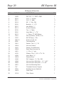
1
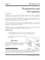
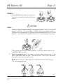
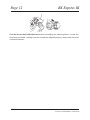
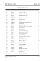
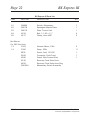
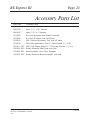
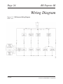
RX-Express III
Owner’s Manual
RX-Express III
Table of Contents
Page
Machine Specifications .............................................. 1
Preparation and Precautions ....................................... 2
Operation ................................................................. 4
Cleaning Instructions ................................................. 6
Automatic Scrubber Option and Parts List .................... 7
Maintenance ........................................................... 10
Repair Guide ............................................................ 13
Machine Parts and Parts Lists .................................... 15
Accessory Parts List ................................................. 23
Wiring Diagram ........................................................ 24
Warranty Repair Policy .............................................. 25
Copyright© 2006
MAN-182-404
No part of this manual may be reproduced or used in any form or by any means (i.e. graphic, electronic, photocopying or electronic
retrieval systems) without the express written permission of the HYDRAMASTER8 Corporation. All rights reserved.
Revised May 23, 2006
Machine Specifications
Size: 46” L x 38 1/2” H x 15” W
Weight: 110 lbs.
Gearbox Oil Capacity: 14 oz.
Vacuum Motor: (2) Two Stage 5.7”
107” H20 Lift - 197 CFM
Solution Pump: Diaphragm Type, Continuous Duty, By-Pass
1.25 GPM - 60 PSI Max
Solution Tank Capacity: 12 gallons
Recovery Tank Capacity: 12 gallons
Head Speed: 130 RPMs
Motor:
115 volts
1/2 HP
5.6 amps
Automatic Scrubber Attachment Kit:
1 Squeegee Attachment
1 Trailer Hook
1 Pad Driver Head or Brush Head Assembly
1 Head Removal Wrench
CleanMaster,
a Division of HydraMaster Corporation
01/10/00
Page 2
RX Express III
Preparation and
Precautions
TO PREPARE...
Carefully remove the unit from its shipping container and inspect for damage.
If damage from shipping has occurred, notify the carrier immediately.
The unit may come partially disassembled. Please refer to the exploded view for
a proper tank configuration. Remove the solid shipping plug from the top of the
gearbox and replace it with the vented plug provided.
If there is any evidence of oil on any of the packaging material, or in the machine
itself, it may have come from the gearbox of the unit. Check the oil level of the
gearbox prior to the operation of the unit.
Important: Remove the solid shipping plug from the top of the gearbox and replace
it with the vented plug provided before operating the machine.
PRECAUTIONS
1. To avoid hazardous conditions, do not use your machine in areas
where flammable and/or explosive vapors or dust are present.
2. Connect only to a grounded (3 wire) outlet.
See illustration.
! WARNING
To reduce risk of electrical shock, use the equipment indoors or contained within a vehicle (i.e.
service van). Do not expose the machine to
weather.
GROUNDING INSTRUCTIONS:
The RX-Express should be grounded while in use to protect the technician from electrical shock. The power cords are equipped with suitable three conductor plugs. If
grounded outlets are not available, use three way adapters (see Figure B).
1/10/00
CleanMaster,
a Division of HydraMaster Corporation
RX Express III
Page 3
GROUNDING INSTRUCTIONS (cont.) :
The green (or green and yellow) conductor in the cord is the grounding wire. Never
connect the grounding blade to a live terminal. Your terminal is designed to be used
on less than 150 volts and has plugs resembling the one shown in Figure A. A
grounding adapter is available locally for connecting plugs to 2-prong receptacles.
The green (or green and yellow) right lug extending from the adapter must be connected to a properly grounded outlet.
NOTE: Use only three wire extension cords which have three prong groundingtype plugs and three prong receptacles or adapters that accept the appliance’s
plug. Replace or repair any damaged cords.
3.
Always disconnect the machine from the electrical outlet before servicing.
4.
Water heaters, when required, should be installed in-line, downstream of
this unit. Damage to the pumps will occur if water temperature exceeds
160 degrees.
5.
Empty the entire machine of water before trying to lift it.
6.
Do not allow the recovery tank to overfill with liquid or foam. If foam
occurs, a defoamer should be used.
7.
After each use of the machine, rinse out and empty the recovery tank.
Then, with the recovery lid open and the vacuum hose off, run the
vacuum motor to allow the tank to dry.
8.
Do not expose the machine to freezing temperatures.
CleanMaster,
a Division of HydraMaster Corporation
1/10/00
Page 4
RX Express III
Operation
CONTROLS
There are three switches installed in the dash box located on the main handle assembly, one each for the vacuum pump, cleaning head, and solution pump. The handle
also contains a trigger for activating the solution valve.
MANEUVERABILITY
The ease of handling the RX-Express is a direct result of the rotary extractor head. Its
natural cleaning motion provides the “drive”
for the unit. The slightest push or pull against
the foam handle provides ample effort in
guiding the RX-Express through its cleaning
paces. Pivoting on its large front tires and
the swivel casters in the rear
allow the RX-Express to glide in and out of
tight spaces and turn on a dime.
CLEANING PATTERN
To achieve maximum results from your unit,
it is recommended that you clean in a back-and-forth motion while overlapping each
cleaning pass by fifty percent. The more soiled the area to be cleaned, the slower the
speed of the cleaning passes. This allows the machine more time to work. After
cleaning an area approximately six feet square, turn off the solution switch and make
vacuum-only “dry passes” over the area to assure maximum water removal and a
faster drying time.
1/10/00
CleanMaster,
a Division of HydraMaster Corporation
RX Express III
Page 5
PUMP PRIMING MODE
Connect the auxiliary pump line supplied with the unit to
the male coupler at the rear of the machine. Disconnect
the vacuum hose intake from the left side of the recovery tank and place the end of the auxiliary line up into
the opening. Using your hand to create a seal around
the line, turn on the vacuum and solution pumps until
you see water coming out of the hose.
EMPTY MODE
Connect the auxiliary pump line to the
male coupler at the rear of the machine
and place the other end into a drain.
Turn on the solution switch and allow
the remaining water to be pumped free.
On the star wheel, two one-inch rubber plugs have been inserted into the plastic hub.
This is to increase the airflow of the electric vacuum motor and speed up drying time.
Remove the plugs when cleaning the star to prevent the buildup of debris in the hub.
CleanMaster,
a Division of HydraMaster Corporation
1/10/00
Page 6
RX Express III
Cleaning Instructions
1.
Fill the solution tank with hot water. The higher the temperature of the
water, the better the cleaning action of the machine and the chemicals
used. However, do not exceed a water temperature of 160 F. When
accessible, fill the machine directly from a utility sink. When this is not
an option, a clean, five gallon bucket will suffice. Add the necessary
chemicals. Now you are ready.
! CAUTION
Only non-foaming cleaning solutions can be used and absolutely no harsh
solvents or petroleum products. They will decrease the life of rubber gaskets,
diaphragms and seals.
2.
Attach the power cord to a properly grounded 20 amp receptacle.
3.
4.
Position the machine in the area to be cleaned.
Lower the cleaning head into its operating position by releasing the latch
located just behind the right front wheel.
5.
Turn on the switches marked VACUUM PUMP, SOLUTION PUMP and
CLEANING HEAD.
6.
To control the flow of solution, pull on the levers located on the handle.
7.
When making a “dry pass” release the levers on the handles.
8.
At completion, dispose of the dirty water in the correct manner. Also,
rinse the recovery tank thoroughly before reusing the machine.
NOTE: To remove any standing water in the solution tank before storing,
simply attach the three foot clear hose to the rear of the machine. Place
the other end of the hose in the recovery tank and turn on the pump to
evacuate the remaining water.
9.
1/10/00
At the end of the day, perform the daily maintenance scheduled.
NOTE: The daily maintenance will prevent any chance of accidental
freezing.
CleanMaster,
a Division of HydraMaster Corporation
RX Express III
Page 7
Automatic Scrubber Option
THE KIT INCLUDES:
One (1) Squeegee Attachment (mounting hardware included)
One (1) Trailer Hook
One (1) Pad Driver Head or Brush Head Assembly
One (1) Head Removal Wrench
INSTALLATION INSTRUCTIONS
1. Remove the tanks. Place the machine on its right side
and remove the standard cleaning head.
2. Thread on the cleaning head of your choice. Make sure
that it mounts counterclockwise. If you are using the
pad driver head, select the proper pad for the application.
3.
Attach the squeegee assembly to the rear of the
machine as seen below.
With the machine in its upright (cleaning) position,
hook
the cable retainer over the crossbar to
“disengage” the squeegee.
4. Replace the tanks. Add the appropriate solution.
Lower the head onto the floor surface and turn on
the head and vacuum switches.
IMPORTANT: DO NOT turn on the pump switch.
Use the levers on the handle to control the flow of
solution.
5. To resume carpet cleaning capabilities, remove the pad driver head with the
wrench provided. Place the tip of the wrench into the holes in the pad
and
rotate in a clockwise direction.
CleanMaster,
a Division of HydraMaster Corporation
1/10/00
Page 8
RX Express III
RX Express III Parts with Pad Driver(079-054)
PART NO
DESCRIPTION
033-039
Clamp, 1½" Spring - Wand Holder
1
094-009
143-007
164-001
174-003
016-053
033-099
076-023
Nut, ¼-20 s/s Nylock
Screw, ¼-20 x 1" Eye Bolt
Tool, Head Remover
Washer, ¼" s/s Flat
Pad Driver Disk
Clamp
Jet, H 1/8" VV 8004 s/s - Port RX’s
Nipple, 1/8" Brass Close
Coupler, 1/8" Machined Rotary Union Fitting
Plug, 1/8" Brass
Double Thread RX Vac Hub
Spacer, Floor Scrub Brush/Pad
Bracket, Vac Nozzle Extension
Cable, Vacuum Nozzle Lift
Clamp, Floor Scrub Cable
Handle, Floor Scrub Hook
Cuff, 1½" Gray - For Wire Reinforced Vac Hose
Knob, Vac Inlet Manifold
Vac Nozzle
Hose, 1½"Vac w/ Wire - Gray
Squeegee Material - 1" x 1/8" x 26"
Extrusion Only - 28" Floor Scrubber
Screw, ¼-20 x 1" Eye Bolt
Screw, 10-24 x ¼ Pan Head Phillips
Spacer, ¼ x 5/16 - s/s Solenoid Valve
Spring
Wheel, Floor Scrubber Wall Guard
Caster, Floor Scrubber Vac Nozzle
2
1
1
2
1
1
052-057
052-288
106-001
107-020
154-101
015-144
025-013
033-059
061-100
052-432
061-031
064-020
068-324
131-098
131-099
143-007
143-533
154-001
155-013
177-021
177-022
3/31/00
QTY
1
1
1
5
1
1
1
2.5 Ft
2
1
2
1
1
2.125 Ft
2
2
1
8
2
1
2
1
CleanMaster,
a Division of HydraMaster Corporation
RX Express III
Page 9
RX Express III Parts with Brush Assembly (079-053)
PART NO
DESCRIPTION
033-039
Clamp, 1½" Spring, Wand Holder
1
094-009
143-007
143-118
164-001
174-003
016-051
Nut, ¼-20 s/s Nylock
Screw, ¼-20 x 1" Eye Bolt
Screw, #8 x ½" Hx WS Head
Tool, Head Remover
Washer, ¼" s/s Flat
Brush, Floor Scrub
2
1
2
1
2
1
076-023
052-057
052-288
106-001
107-020
154-101
015-144
025-013
033-059
061-100
052-432
061-031
064-020
068-324
131-098
131-099
143-007
143-533
154-001
155-013
177-021
177-022
Jet, H 1/8 VV 8004 s/s - Port RX’s
Nipple, 1/8" Brass Close
Coupler, 1/8" Machined Rotary Union Fitting
Plug,1/8" Brass
Double Thread RX Vac Hub
Spacer, Floor Scrub Brush/Pad
Bracket, Vac Nozzle Extension
Cable, Vacuum Nozzle Lift
Clamp, Floor Scrub Cable
Handle, Floor Scrub Hook
Cuff, 1½" Gray - For Wire Reinforced Vac Hose
Knob, Vac Inlet Manifold
Vac Nozzle
Hose, 1½" Vac w/ Wire - Gray
Squeegee Material - 1" x 1/8" x 26"
Extrusion Only - 28" Floor Scrubber
Screw, ¼-20 x 1" Eye Bolt
Screw, 10-24 x ¼ Pan Hd Phillips
Spacer, ¼ x 5/16 - s/s Solenoid Valve
Spring
Wheel, Floor Scrubber Wall Guard
Caster, Floor Scrubber Vac Nozzle
CleanMaster,
a Division of HydraMaster Corporation
QTY
1
1
1
5
1
1
1
2.5 Ft
2
1
2
1
1
2 .125 Ft
2
2
1
8
2
1
2
1
3/31/00
Page 10
RX Express III
Maintenance
MONTHLY...
1.
Check the oil level in the gearbox on a monthly
basis. This is a permanent lubricated gearbox. You
do not need to change the oil. However, maintain
ing the proper oil level is important. To check the
oil level, remove the vent plug and look into the
gearbox. Turn the “star” until you can see the
inspection hole in the gear. With the unit sitting
flat, the oil level should be up to, but not over, the
middle of the gear. If oil needs to be added, use a
quality 80-90 weight gear oil.
HELPFUL HINT: When checking the oil level in the gearbox, use a toothpick as
a dipstick. The oil level should read 3/8".
2.
Remove and rinse the filter screen from the flow control valve.
3.
Change the felt seal. This is recommended after every ten hours
of use. (For step by step instructions on removing the cleaning
head and the seal, please refer to the “REPAIR GUIDE”
section.) Always keep a spare felt seal soaking in 30 weight
oil. By immersing the felt in oil, it will expand like a sponge and providE
sufficient seal for a good vacuum. Place the worn seal back in the oil bath
to rejuvenate.
HELPFUL HINT: An ideal container in which to soak the spare felt seal
is a commercial tuna can. It is the right size and shape and does not
require a large amount of oil.
After placing the refreshed, oil-soaked felt seal in the hub, coat the
surface with 30 weight gear oil. Lightly oil the inner hub threads
before reattaching the cleaning head to the machine.
1/10/00
CleanMaster,
a Division of HydraMaster Corporation
RX Express III
Page 11
WEEKLY...
1. Clean the Recovery Tank thoroughly by
removing the tank and rinsing with clear
water.
! CAUTION
DAILY...
1.
2.
Clean off any accumulated debris on the gearbox shaft or inside the threaded
portion of the hub. An accumulation of debris around the gearbox shaft, if
not removed, may damage the gearbox oil seal resulting in loss of oil in the
gearbox. If the gearbox is operated without oil, severe damage may occur.
(This requires removing the cleaning head. To do this, please refer to the
“REPAIR GUIDE” section.)
Check the applicator jets in the head to insure a proper solution flow. If the
flow is restricted, clean the jets. Twist the jet out. Turn it over. Blow out
any obstructions and reinstall the jet.
NOTE: Do not use any sharp objects to clear obstructions from the jets.
This will damage the jets
CleanMaster,
a Division of HydraMaster Corporation
1/10/00
Page 12
RX Express III
Coat the motor shaft with lubricant before reinstalling the cleaning head. Locate the
head onto the shaft, making sure the threads are aligned properly, and rotate the head
counterclockwise.
1/10/00
CleanMaster,
a Division of HydraMaster Corporation
RX Express III
Page 13
Repair Guide
IMPORTANT: Make sure the machine is unplugged before the removal of any
electrical parts.
Removal of Cleaning Head:
1. First, unscrew the head in the same direction it turns
during operation (or clockwise when looking from the
underside).
2. Once you have loosened the assembly, spin if off
with your hands. If the cleaning head is difficult to
remove, you may use a ¾” socket wrench on the
exposed center nut.
Replacing the Felt Seal:
A worn or “dried out” felt will not form a proper vacuum seal. This will impair the
extraction capabilities of the unit. Therefore, the carpets are left more wet than is
desirable.
1. Remove cleaning head assembly.
2. Make sure felt is saturated with oil to insure a proper seal.
3. Remove and reverse seal so that “new” face is against hub.
NOTE: Alternating sides will temporarily extend the life of the felt.
How ever, the seal may need to be replaced.
4. Reinstall head assembly.
NOTE: When reinstalling the head assembly, you should be able to “feel” the
felt compacting against the seal plate during the last quarter rotation of the
head.
Removal of Vacuum Motor:
1. Disconnect machine from power source.
2. Remove hose from end of vacuum motor.
3. Remove ¼-20 screws from the vacuum motor.
4. Lift motor.
5. Disconnect wires at terminal clips.
Removal and Re-Installation of Solution Pump:
1. Disconnect machine from power source.
2. Check that all water has been evacuated from unit.
3. Disconnect ½” hoses on either side of pump.
4. Remove four (4) 10-24 screws and nuts mounting pump to side of frame.
CleanMaster,
a Division of HydraMaster Corporation
1/10/00
Page 14
RX Express III
Removal
5.
6.
7.
and Re-Installation of Solution Pump (cont.):
Disconnect wires at wire nuts.
Remake wire connections with new wire nuts.
Reinstall in reverse order.
Removal
1.
2.
3.
4.
5.
6.
of Flow Control Valve:
Disconnect machine from power source.
Evacuate all water from unit.
Disconnect ¼" hose attached to valve.
Disconnect wires.
Unscrew the valve from the pump.
Lift complete valve assembly from unit.
Removal
1.
2.
3.
4.
5.
6.
7.
8.
of Cleaning Head / Pivot Frame Assembly:
Disconnect machine from power source.
Remove vacuum hose attached to front of head.
Remove hose attached to rotary union.
Disconnect wires at rear of motor.
Remove control link from rear of shaft.
Loosen two (2) set screws in pivot bearing.
Remove spring from lifting mechanism.
Pull head forward to disengage from frame.
1/10/00
CleanMaster,
a Division of HydraMaster Corporation
RX Express III
Page 15
Machine Parts
Figure 1-1 RX Express Head Assembly
CleanMaster,
a Division of HydraMaster Corporation
1/10/00
Page 16
RX Express III
RX Express III Head Assembly
ITEM
PART NO
1
2
000-052-099
000-052-276
3
4
5
6
7
8a
8b
9
10
11
12
13
14
15
16
17
18
19
20
21
22
23
24
25
26
000-068-017
000-059-001
000-006-009
000-105-008
000-143-166
000-107-089
000-107-020
000-068-174
000-143-012
000-064-012
000-094-009
000-143-162
000-076-079
000-052-089
000-052-080
000-057-047
000-055-057
000-094-009
000-085-012
000-015-145
000-143-080
000-143-096
000-174-021
000-106-014
604-052-013
05/23/2006
DESCRIPTION
QTY
Insert, #26
1
Rotary Union, 1/8” NPT
1
3
3
Hose, /8 “ Rubber
4 /16 Ft
Gearbox, Complete - Spur
1
Base, High Speed
1
Plate, Cast Base - Seal
2
Screw, ¼“- 20 x 1” s/s Button-hd Cap Screw 1
Star, Stainless Steel Heat Treated
1
Hub, Double Thread RX Vacuum
1
Hose, 1” ID Gray - Vacuum
5
5
5
Screw, /16 - 18 x ¾” s/s Hex Hd Cap Screw
Head, RX Skid Assembly
5
Nut, ¼ - 20 s/s Nylok
5
Screw, 5/16”x 1”, ¼ - 20 s/s Stripper
5
Jet, 95015 Quick Release
5
Elbow, 1/8” Brass Female
5
1
Nipple, /8” x 4” Brass
5
Gasket, Felt Hub
1
Frame, Pivot
1
Nut, ¼ - 20 s/s Nylok
2
Link, Torsion Bar
1
Bracket, Auto Floor Scrub Hitch
1
Screw, ¼ - 20 x 1” s/s Socket Hd Cap Screw 2
Screw, 3/8 - 16 x ¾” s/s Hex Hd Cap Screw 5
Washer, 3/8“ Lock
12
Plug, Gearbox Vent
1
RX Express III Electric Motor Assembly
1
CleanMaster,
a Division of HydraMaster Corporation
RX Express III
Page 17
Figure 1-2 RX Express Main Assemblies
CleanMaster,
a Division of HydraMaster Corporation
1/10/00
Page 18
RX Express III
Figure 1-3 RX Express Main Assemblies
1/10/00
CleanMaster,
a Division of HydraMaster Corporation
RX Express III
Page 19
Figure 1-4 RX Express Handle Assembly
CleanMaster,
a Division of HydraMaster Corporation
1/10/00
Page 20
RX Express III
RX Express III Parts List
ITEM
PART NO
DESCRIPTION
QTY
1
2
3
4
5
6
7
8
9
10
11
12
13
14
15
16
17
18
19
20
21
22
23
24
25
26
27
28
29
H243
B102
B101
B103
B105
B107
B119
B135
B160
B172
C301
C307
CM113
E525
G001
G004
G041
G056
H201
H212
H229
G009
H244
H624
H623
H601
31/8"
P750
G003
PVC 90° 1-½ FMT x FMS
Q.D. ¼" Female
Q.D. ¼" Male
90° ¼" M x FM
Bushing, ¼" x 3/8"
Hex Nipple, ¼"
Suction Strainer
Tee, ¼" Male
Hose Barb, ½" x 3/8"
½" Barb x 3/8" MPT Elbow
Vacuum Motor (2STG) 115v
60 PSI Pump, 115v
Solution Tank Lid
Terminal Block
Gasket, Thin 1-½" ID
Vacuum Gasket
Gasket, Dual Manifold
Deck Plate Vacuum Lid
¼"-20 x ½" bolt
Washer, Flat 1" O.D. x 9/16" I.D.
Inlet, Black 1½"
Plastisol Boot
PVC Adaptor, 1½" M x FM
Vacuum Hose Wire Rein., 1½" x 60"
Vacuum Hose Wire Rein., 2" x 42"
Vacuum Mounting Plate
Threaded Vacuum Support
Parallel Vacuum Manifold
Foam Filter
1
1
2
3
3
2
1
1
1
1
2
1
1
1
3
2
1
1
6
4
3
1
2
1
1
1
6
2
1
30
G014
Filter Screen
1
1/10/00
CleanMaster,
a Division of HydraMaster Corporation
RX Express III
Page 21
RX Express III Parts List
ITEM
PART NO
DESCRIPTION
31
32
33
34
35
36
37
38
39
40
41
42
43
44
45
46
47
48
49
50
51
52
53
54
55
56
57
58
59
60
H342
AH104
AH110
CM101
CMP102
CMP103
CMP104
CM003A
CM117
E515
H297
CM111
CM112
H372
E550
H220
H221
H352
H252
CM119
H202
CM110
CM109
H628
H392
CM107
CM115
CM108
H219
¼-20 x 1" Bolt
Solution Hose, 15¾
Solution Hose, 15¾
Base
Solution Hose Tank
Vacuum Tank
Handle
Switch plate, Momentary (RX)
Switchplate
Switches, Rocker
Screw, No. 8 x ½" Sheet Metal
Upper Handle
Handle Brace
Conduit, Flexible, 22"
Power Cord 12/3, 30"
Fitting, Strain Relief
Nut, Steel Lock
Connector, Heyco Straight
Caster, 4"
Bearing, Block, ½"
Bolt, 1/1-20 x ¾"
Lower Handle
Bracket, Handle
Clevis Assembly
10" Rear Wheel
Lift Bar
Bracket, Lift Lower
Axle/Lever Assembly
Axle Cap, ½"
Bearing, Pillow Block
CleanMaster,
a Division of HydraMaster Corporation
QTY
12
1
1
1
1
1
1
1
1
1
4
1
1
2
1
1
1
1
2
2
13
1
1
1
2
1
1
1
2
1
1/10/00
Page 22
RX Express III
RX Express III Parts List
ITEM
61
62
63
64
65
PART NO
DESCRIPTION
CM006
CM118
CM116
H316
H217
Switch, Momentary
Squeegee Adaptor Plate
Plate, Torsion Link
Bolt, 1/1-20 x 1½"
Clamp, Hose H28
Not Shown:
For 230 Volt Units
13
C303
14
C306
E530
G029
H296
G126
H633
CM103A
3/31/00
QTY
Vacuum Motor, 230v
Pump, 230v
Power Cord, 12/3 50’
Connector, Push/Twist
Guard, Wire Formed (Fan)
Recovery Tank Drain Hose
Recovery Tank Drain Hose Plug
Momentary Switch Assembly
1
1
1
4
2
2
11
1
1
1
CleanMaster,
a Division of HydraMaster Corporation
RX Express III
Page 23
Accessory Parts List
PART NO
DESCRIPTION
068-194
068-332
079-053
079-054
163-023
164-020
100-011-101
190-041-020
190-041-021
190-041-022
Hose, 1½" x 15' Vacuum
Hose, 15' F x F Solution
Kit, Auto Scrubber with Brush Assembly
Kit, Auto Scrubber with Pad Driver
CM-1 Deluxe Upholstery Tool with LP Valve
CM-CHSV Upholstery Tool 4", Closed Head, 1½" DIA
CM S11A Carpet Wand 11" LP Powder Coated, 1½" s/s
Rotary Extractor Pad Driver with Hub
Rear Assembly, Auto Floor Scrubber
Rotary Extractor Brush Assembly with Hub
CleanMaster,
a Division of HydraMaster Corporation
3/31/00
Page 24
RX Express III
Wiring Diagram
Figure 1.5 RX Express Wiring Diagram
D4551 Rev —
1/10/00
CleanMaster,
a Division of HydraMaster Corporation
RX Express III
Page 25
Warranty Repair Policy
When requesting warranty information, call or write and provide the following
information:
1.
When and where the equipment in question was purchased.
2.
Model and serial number of the machine.
3.
Part number and description of the part.
4.
Description of failure or defect.
Upon receipt of the above information, a Material Return Authorization will be issued.
All packages should be prepaid and clearly marked with the Material Return Authorization Number. If these conditions are not met, shipment will be refused.
After evaluation, the item(s) will be repaired or replaced at our discretion.
If failure or defect is the result of physical abuse, or if the warranty period has expired, repairs will be charged to the customer.
For service, contact the distributor where the machine was purchased
or call our Customer Service Department.
Monday through Friday • 8:00 am to 5:00 pm PST
Parts:
Service:
Parts and Service FAX:
CleanMaster,
a Division of HydraMaster Corporation
(425) 775-7276
(425) 775-7275
(800) 426-4225
1/10/00
Page 26
1/10/00
RX Express III
CleanMaster,
a Division of HydraMaster Corporation