1
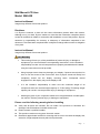
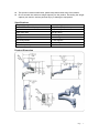
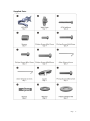
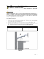
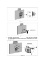
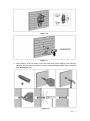
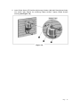
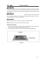
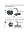
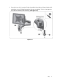
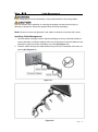
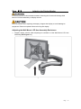
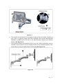
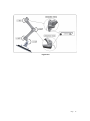
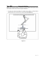
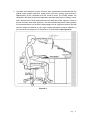
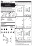
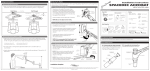
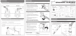
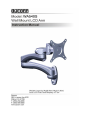
Wall Mount LCD Arm Model: WA540S Instruction Manual Images may different from actual product Disclaimer It is Dyconn’s intention to have all the correct information present within this manual. Although we try our best, Dyconn makes no claim that the information comprised herein covers all conditions or details in connection with installation or use of this product. Dyconn assumes no responsibility for accuracy or adequacy of information comprised in this document. The information comprised here is subject to change without notice or obligation of any kind. Instruction Manual Images may different from actual product This warning informs you of the possibilities of personal injury or damage to equipment if you do not follow the corresponding instructions. It is the installer's responsibility to make sure all components are properly assembled and installed using the instructions manual provided. Using improper screw sizes may damage your display. If spacers are required, be sure to use the screws of the correct size. Use of proper screws will easily and completely thread into the display mounting holes. Inadequate thread engagement in the display may cause display to fall. It is the installer’s responsibility to make sure the combined weight of all components does not exceed weight capacity of 17.6lbs (8Kg). Exceeding weight capacity can result in severe personal injury or damage to equipment. Allowing any part of your component cables to be caught between movable parts can result in serious personal injury or damage to equipment. Please read the following warning before installing Verify that all parts are included. Do not install if the products or hardware are damaged. Not all hardware included will be used. Please contact a qualified installer. This product contains moving parts. Use with caution. Determine approximate location for mounting and be sure to consider the display size, extension, height adjustment and pitch/roll requirements. Page 2 This product contains small items; please keep these items away from children. Do not exceed the maximum weight capacity for this product. Exceeding the weight capacity can result in serious personal injury or damage to equipment! Specifications Weight Capacity 17.6lbs (8Kg) Suits LCD Flat Panel Displays 12”(300mm)-24”(610mm) Maximum Extension 18”(457mm) Depth from Wall 3.2”(81.5mm) Tilt Adjustment +/- 90 degrees Display Orientation +/- 360 degrees Swivel Adjustment +/- 90 degrees Pivot +/- 180 degrees VESA Compatibility 75x75mm and 100x100mm Product Dimension Page 3 Supplied Parts Page 4 Required Tools ASSEMBLY and INSTALLATION INSPECT THE MOUNT BEFORE ASSEMBLY 1. Carefully inspect/verify that all components are present. 2. If the mount/components are damaged or missing, please contact the company/seller of the product you purchased this unit from and report the issue. Note: Read all assembly instructions before starting the installation process. Page 5 Step 【1】 Wood Wall Installation Drilling into electrical wires or cables can cause serious personal injury! Always make certain that the area behind mounting area is free of electrical wires and cables before drilling or installing. Improper installation can lead to the mount falling causing severe personal injury or damage to equipment. It is the installer’s responsibility to make sure the combined weight of all components does not exceed weight capacity of 17.6lbs (8Kg). The manufacturer accepts no responsibility for incorrect installation. Wood Wall Installation 1. To determine Wall Plate (2) mounting height, add 1” (25.4mm) to the mounting height from the top of the table (See Figure 1-1). 2. Place the Wall Plate (2) on the wall. Mark location with pencil (See Figure 1-2). 3. Use awl or stud finder to find stud location. Ensure marks are in the center of wood stud. Drill pilot holes and ensure pilot holes are straight (See Figure 1-3). Wood Pilot Pilot hole size Pilot Drill Depth 1/8" 2" 4mm 50mm Figure 1-1 Page 6 Figure 1-2 Figure 1-3 4. Insert Philips Screw ST6.3x65mm (3) through Washer (14), Wall Plate (2) and finally into pilot hole. Repeat for remaining Philips Screws. Tighten Philips Screw securely (See Figure 1-4). Figure 1-4 Page 7 Step 【1】 Concrete Wall Installation Drilling into electrical wires or cables can cause serious personal injury! Always make certain that the area behind mounting area is free of electrical wires and cables before drilling or installing. Improper installation can lead to the mount falling causing severe personal injury or damage to equipment. It is the installer’s responsibility to make sure the combined weight of all components does not exceed weight capacity of 17.6lbs (8Kg). The manufacturer accepts no responsibility for incorrect installation. Note: Select the proper hardware for this installation. Concrete Wall Installation 1. To determine Wall Plate (2) mounting height, add 1” (25.4mm) to the mounting height from the top of the table (See Figure 1-5). 2. Place the Wall Plate (2) on the wall. Mark the mounting location (See Figure 1-6). 3. Drill the concrete hole and ensure the pilot holes are straight and completely through concrete wall (See Figure 1-7). Concrete Pilot Pilot hole size Pilot Drill Depth 5/16" 2.36" 10mm 60mm Figure 1-5 Page 8 Figure 1-6 Figure 1-7 4. Insert Anchor (13) into anchor hole and seat with gentle tapping from hammer. Hammer anchor screw until anchor has fully collapsed against back side of concrete wall (See Figure 1-8). Figure 1-8 Page 9 5. Insert Philips Screw ST6.3x65mm (3) through Washer (14), Wall Plate (2) and finally into anchor (13). Repeat for remaining Philips Screws. Tighten Philips Screws securely (See Figure 1-9). Figure 1-9 Page 10 Step 【2】 Display Installation Using improper screws or screw size may damage your display. If spacers are required, be sure to use screws of the correct size. Proper screws will easily and completely thread into the display mounting holes. Inadequate thread engagement in the display may cause display to fall. It is the installer’s responsibility to make sure the combined weight of all components does not exceed weight capacity of 17.6lbs (8Kg). Exceeding weight capacity can result in severe personal injury or damage to equipment. Wall Mount LCD Arm will only work when a display is properly installed. Note: All Spacers or Screws used should be the same length. Attaching the Display 1. Ensure Tilter Mount Bracket of Wall Mount LCD Arm Assembly is able to swivel and tilt easily. Adjust, if necessary, before proceeding to next step. 2. Carefully place the display face down on protective surface (See Figure 2-1). Figure 2-1 Page 11 3. Determine depth of recessed mounting holes relative to the back of the display. 4. Select the proper length of Screws (6, 8) that suit your monitor’s specifications. Place the Spacers (4) on the back of display, follow by positioning the mounting holes in the Tilter Mount Bracket so that the mounting holes on the Tilter Mount Bracket and Spacers (4) are aligned (See Figure 2-2). Figure 2-2 5. Using a Philips Screwdriver, install selected Screws (6, 8) through mounting holes on Tilter Mount Bracket and Spacers (4), and into the display monitor. Tighten Screws with Philip Screwdriver so the Tilter Mount Bracket is firmly attached to the display monitor. Do not over tighten the Screws. Stop immediately if you encounter any resistance (See Figure 2-3). Figure 2-3 Page 12 Step 【3】 Attaching Wall Mount LCD Arm Assembly Wall Mount LCD Arm will only work when a display is properly installed. Attaching the LCD Arm Assembly 1. Attach the Wall Mount LCD Arm Assembly (1) to Wall Plate (2) by placing the LCD Arm Assembly downward, onto the top of the Wall Plate pole (See Figure 3-1). 2. Once the Wall Mount LCD Arm Assembly is in desired position, tighten with Hex Grub Screw using the Hex Allen Wrench 2.5mm (10) so the assembly is firmly in place (See Figure 3-2). Figure 3-1 Figure 3-2 Page 13 3. Place the Cover (11). Insert the Phillips Screw M6x12mm (12) and Plastic Washer (15) and tighten using a Phillips Screwdriver. Do not over tighten. This is to help prevent the LCD Arm Assembly from detaching (See Figure 3-3). Figure 3-3 Page 14 Step 【4】 Cable Management Ensure Wall Mount LCD Arm Assembly is fully extended before connecting cables. Exercise caution when attaching or removing the display to avoid personal injury or damage to equipment. Disconnect power before removing the display. Note: Be sure to leave enough slack in the cables to allow for movement of the arms. Installing Cable Management 1. Connect cables to display monitor. Adjust the display to its fully extended position to ensure that there is sufficient cabling at the end of the Arms so that the cables are not stretched or pulled out when the display is moved (See Figure 4-1). 2. Feed the cables through the cable bracket entry slot on the underside of the arms as shown (See Figure 4-2). Figure 4-1 Figure 4-2 Page 15 Step 【5】 Adjusting the Display Monitor Forced movement of Mount Bracket without loosening the Screws will damage Wall Mount LCD Arms Assembly or display monitor. Exercise caution when adjusting the display. Support the display to avoid damage to equipment. Disconnect power before removing the display. Adjusting the Wall Mount LCD Arm Assembly Resistance 1. Support display monitor when adjusting the resistance of the Wall Mount LCD Arm Assembly (See Figure 5-1). Figure 5-1 Page 16 Adjusting the Mount Bracket Resistance 2. The product is engineered to control the resistance in the Tilter Mount Bracket to suit your display swivel of +/- 90 degrees, tilt of +/- 90 degrees and also display orientation of +/- 360 degrees. You can easily control the amount of resistance in the Tilter Mount Bracket to suit your display monitor. 3. If the weight of the display monitor causes the Tilter Mount Bracket to tilt, it may be required to adjust the Tilter Mount Bracket joint to suit your display monitor tilt position of +/- 90 degrees. This can be done by using Hex Allen Wrench 4mm (9). To increase the resistance of the Tilter Mount Bracket to secure tilt position, adjust the M5x15mm Tension Hex Socket Cap Screw located around the Tilter Mount Bracket using the supplied 4mm Hex Allen Wrench (See Figure 5-2). 4. To increase or decrease the resistance of the Pivot Joint to suit display monitor swivel, adjust the Tension Hex Cap Screw located on the front side of the Wall Mount LCD Arm to secure the position (See Figure 5-3). 5. To increase the resistance, tighten the M5x15mm Tension Hex Socket Cap Screw using Allen Wrench 4mm (9) in a clockwise direction. To decrease the resistance, loosen the M5x15mm Tension Hex Socket Cap Screw using Allen Wrench 4mm (9) in a counterclockwise direction. Figure 5-2 Page 17 Figure 5-3 6. This product is manufactured and designed to adjust quickly and easily according to your needs. To adjust the height, remove the Extension Arm (1) from Wall Plate (2) followed by reattaching the LCD Arm to the Wall Plate (2) to achieve your desired position (See Figure 5-4). 7. If this product tends to automatically move to the side, tension adjustment may be required on the LCD Arm to set your display monitor arm to the desired position. This can be done by using Hex Allen Wrench 2.5mm (10) (See Figure 5-5). Figure 5-4 Page 18 Figure 5-5 Page 19 Step 【6】 Ergonomic Guidelines Note: Proper ergonomic design is necessary to prevent repetitive strain injuries, which can develop over time and can lead to long-term disabilities. 1. To ensure the correct focal distance for ultimate visual comfort, a viewing distance between 460mm (18”) to 610mm (24”) is recommended (See Figure6-1). Figure 6-1 Page 20 2. To assess the fit between a person and their work, ergonomists recommended that the optimal screen position should be slightly below eye level. Viewing angle should be approximately 10°-20° downward onto the screen’s center. The lumbar (bottom five vertebrate in the spine) needs to be supported to decrease disc pressure. Sitting in a chair with a backrest that inclines backwards and has adequate lumbar support is critical to prevent excessive lower back pressures. The recommended ergonomic seating position to minimize pressures is to sit with the wrists straight at a 90° angle from the floor and seat and knee angle must also be at a 90° angle. Angular adjustment to reduce reflection on your monitor should range from 5° forward tilt to 15° backward tilt (See Figure6-2). Figure 6-2 Page 21 DYCONN PRODUCT WARRANTY To obtain warranty service, contact Dyconn customer service at (855) 239-2666 or visit www.dyconn.com. Dyconn disclaims any liability for modification, improper installations, or installations over specified weight range. Dyconn will not be liable for any damages arising out of the use of, or inability to use of Dyconn products. Warranty specification is subject to change without prior notice. Page 22