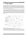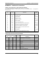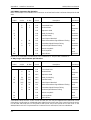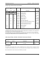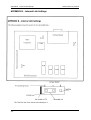
1
AM64/128A
BASE BAND MODEM
USER MANUAL
ATL Part No. 1/203/002/610
Issue 4 - September 2002.
AM64/128A User Manual
THE INFORMATION CONTAINED IN
THIS DOCUMENT IS CONFIDENTIAL TO
ATL TELECOM LTD. AND MAY
NOT BE DISCLOSED OR REPRODUCED IN WHOLE
OR IN PART WITHOUT THEIR WRITTEN CONSENT.
©ATL TELECOM LTD. 2002.
2
Contents
AM64/128A User Manual
CONTENTS
1.
Introduction . . . . . . . . . . . . . . . . . . . . . . . . . . . . . . . . . . . . . . . . . . . . . . . . . . . . .5
2.
Constructional Details . . . . . . . . . . . . . . . . . . . . . . . . . . . . . . . . . . . . . . . . . . . . . .6
2.1
Base Band Modems . . . . . . . . . . . . . . . . . . . . . . . . . . . . . . . . . . . . . . . .6
2.2
Interface Modules . . . . . . . . . . . . . . . . . . . . . . . . . . . . . . . . . . . . . . . . . .6
3.
System Overview . . . . . . . . . . . . . . . . . . . . . . . . . . . . . . . . . . . . . . . . . . . . . . . . . .7
4.
Installation . . . . . . . . . . . . . . . . . . . . . . . . . . . . . . . . . . . . . . . . . . . . . . . . . . . . . .9
5.
4.1
BBM to BBM Link . . . . . . . . . . . . . . . . . . . . . . . . . . . . . . . . . . . . . . . . . .9
4.2
BBM to Line Card Link . . . . . . . . . . . . . . . . . . . . . . . . . . . . . . . . . . . . .11
Menu Operation . . . . . . . . . . . . . . . . . . . . . . . . . . . . . . . . . . . . . . . . . . . . . . . . .12
5.1
Front Panel Features . . . . . . . . . . . . . . . . . . . . . . . . . . . . . . . . . . . . . . .12
5.2
Front Panel Operation . . . . . . . . . . . . . . . . . . . . . . . . . . . . . . . . . . . . . .13
5.3
Status Menu . . . . . . . . . . . . . . . . . . . . . . . . . . . . . . . . . . . . . . . . . . . . .14
5.3.1
5.3.2
5.3.3
5.3.4
5.3.5
5.3.6
Over all Status . . . . . . . . . . . . . . . . . . . . . . . . . . . . . . . . . . . . .14
Alarm Status . . . . . . . . . . . . . . . . . . . . . . . . . . . . . . . . . . . . . . .15
User Rate . . . . . . . . . . . . . . . . . . . . . . . . . . . . . . . . . . . . . . . . .16
Line Rate . . . . . . . . . . . . . . . . . . . . . . . . . . . . . . . . . . . . . . . . .16
Interface Status . . . . . . . . . . . . . . . . . . . . . . . . . . . . . . . . . . . . .16
Mode Display . . . . . . . . . . . . . . . . . . . . . . . . . . . . . . . . . . . . . .17
5.4 Test Menu . . . . . . . . . . . . . . . . . . . . . . . . . . . . . . . . . . . . . . . . . . . . . . . . .18
5.4.1
5.4.2
5.4.3
5.4.4
5.4.5
5.4.6
5.4.7
5.4.8
5.4.9
Local Loop . . . . . . . . . . . . . . . . . . . . . . . . . . . . . . . . . . . . . . . .18
Loop back . . . . . . . . . . . . . . . . . . . . . . . . . . . . . . . . . . . . . . . . .19
Remote Loop . . . . . . . . . . . . . . . . . . . . . . . . . . . . . . . . . . . . . .20
Binary Patterns . . . . . . . . . . . . . . . . . . . . . . . . . . . . . . . . . . . . .21
Data Test . . . . . . . . . . . . . . . . . . . . . . . . . . . . . . . . . . . . . . . . .22
In Service Test . . . . . . . . . . . . . . . . . . . . . . . . . . . . . . . . . . . . . .25
Lamp Test . . . . . . . . . . . . . . . . . . . . . . . . . . . . . . . . . . . . . . . . .26
Self Test . . . . . . . . . . . . . . . . . . . . . . . . . . . . . . . . . . . . . . . . . .26
Communications Channel Loop back . . . . . . . . . . . . . . . . . . . .27
5.5 Rate Menu . . . . . . . . . . . . . . . . . . . . . . . . . . . . . . . . . . . . . . . . . . . . . . . .28
3
AM64/128A User Manual
5.6
Contents
Option Menu . . . . . . . . . . . . . . . . . . . . . . . . . . . . . . . . . . . . . . . . . . . .30
5.6.1
5.6.2
5.6.3
5.6.4
5.6.5
5.6.6
5.7
X.21 . . . . . . . . . . . . . . . . . . . . . . . . . . . . . . . . . . . . . . . . . . . . .30
X.21bis . . . . . . . . . . . . . . . . . . . . . . . . . . . . . . . . . . . . . . . . . . .30
G.703 . . . . . . . . . . . . . . . . . . . . . . . . . . . . . . . . . . . . . . . . . . . .30
Asynchronous Mode . . . . . . . . . . . . . . . . . . . . . . . . . . . . . . . . .31
Signalling Rate . . . . . . . . . . . . . . . . . . . . . . . . . . . . . . . . . . . . .31
Character Length . . . . . . . . . . . . . . . . . . . . . . . . . . . . . . . . . . .32
Configuration Menu . . . . . . . . . . . . . . . . . . . . . . . . . . . . . . . . . . . . . . .33
5.7.1
5.7.2
5.7.3
5.7.4
5.7.5
5.7.6
5.7.7
Master / Slave . . . . . . . . . . . . . . . . . . . . . . . . . . . . . . . . . . . . . .33
Line Rate . . . . . . . . . . . . . . . . . . . . . . . . . . . . . . . . . . . . . . . . .33
X.21 Loop Control . . . . . . . . . . . . . . . . . . . . . . . . . . . . . . . . . .34
Synchronisation Type . . . . . . . . . . . . . . . . . . . . . . . . . . . . . . . .34
64k Mode . . . . . . . . . . . . . . . . . . . . . . . . . . . . . . . . . . . . . . . . .36
Power Level . . . . . . . . . . . . . . . . . . . . . . . . . . . . . . . . . . . . . . .36
Menu Lock . . . . . . . . . . . . . . . . . . . . . . . . . . . . . . . . . . . . . . . .36
Glossary of Terms . . . . . . . . . . . . . . . . . . . . . . . . . . . . . . . . . . . . . . . . . . . . . . . . . . . .37
General Specification . . . . . . . . . . . . . . . . . . . . . . . . . . . . . . . . . . . . . . . . . . . . . . . . .39
Appendix A
Interface Pin Connections . . . . . . . . . . . . . . . . . . . . . . . . . . . . . . . .A1
Appendix B
Internal Link Settings . . . . . . . . . . . . . . . . . . . . . . . . . . . . . . . . . . . .A4
Appendix C
In Service Test . . . . . . . . . . . . . . . . . . . . . . . . . . . . . . . . . . . . . . . . .A8
Appendix D
Approvals . . . . . . . . . . . . . . . . . . . . . . . . . . . . . . . . . . . . . . . . . . .A10
Appendix E
Use on X.21/X.21bis digital circuits . . . . . . . . . . . . . . . . . . . . . . . .A12
Appendix F
Troubleshooting . . . . . . . . . . . . . . . . . . . . . . . . . . . . . . . . . . . . . . .A15
4
Introduction
1.
AM64/128A User Manual
INTRODUCTION
This manual applies to the AM 64/128A Baseband Modem. This modem is manufactured in the U.K. by
ATL Telecom Ltd.
There are six variants, each with a different physical data interface circuit. The ATL Telecom Ltd. part
numbers for these variants are as follows :•
•
•
•
•
•
AM 64/128A - X.21 :
AM64/128A - X.21bis :
AM64/128A - V.35 :
AM64/128A - V.36 :
AM64/128A - RS530 :
AM64/128A - G.703 :
1/203/102/100
1/203/202/100
1/203/302/100
1/203/402/100
1/203/502/100
1/203/602/100
The unit should have an identifying label carrying this number attached to the under side.
Separate interface modules can also be purchased in order to modify the units for operation with a different
DTE interface at a later date.
The BBM can provide synchronous communications at user data rates between 2.4kbps and 128kbps over
a 2 wire twisted pair cable. Asynchronous communication is also provided at data rates up to 19.2kbps.
The BBM can easily be configured using the front panel keys in conjunction with the Liquid Crystal Display
(LCD). The display is operated in a menu type fashion with easy to understand mnemonics, which should
make constant reference to this hand book unnecessary.
Once configured the operation of the BBM is totally automatic, and in the event of line disturbances the
data link is immediately restored without operator intervention.
Chapter 4 (Installation) describes the basic set up procedure and this should be read prior to setting up any
link.
Chapter 5 (Menu Operation) is much more detailed, but should be read to gain an understanding of the
full range of menu facilities available.
The unit is approved for connection to private digital circuits adhering to the X.21 or X.21bis
recommendations (PTO service categories 1 and 2, all rates). Connection of the unit to such circuits is
described more fully in appendix E.
INTERNATIONAL MODELS
Modifications to line cords and power supply leads are available for country specific requirements. In such
cases, line cord pin outs may be different. The basic model is the same, line cords and power cords are
separate plug-in items.
5
Constructional Details
2.
CONSTRUCTIONAL DETAILS
2.1
Baseband Modems
AM64/128A User Manual
The BBM is housed in a black plastic case. On the front panel there is a menu driven LCD display with six
keys and five LED's. On the back panel there is a 3- pin IEC mains inlet socket, an input voltage selector
switch (230V/120V), a 6-way - 4-loaded RJ11 connector type line cord socket, and one data interface
connector. The data interface connector type will be from one of the six user specified interfaces available.
Inside the plastic case is a metal case which contains the main PCB. The metal case is for EMC screening
purposes. The front panel assembly containing the LCD, the keys, and the LED's are attached to the main
PCB by two connectors feeding through the metal case.
The BBM is packed with a 2 meter mains lead, terminating on one end with a UK 3-pin mains plug as
standard (or other plug if specified) and 3-pin IEC connector on the other. Also included is a double ended
FCC connector 6-way 4-loaded RJ11 to BT 631A plug line cord (as standard, however other optional line
cord plugs are available). These are both packed with the unit in separate tie-wrapped polythene bags.
The over all dimensions of the unit are 274L x 251W x 55H mm.
Figure 2.1.1 shows the BBMs front panel.
atl
2.2
AM-64/128A
Interface Modules
Six versions of the AM-64/128A are available, each with a different interface module fitted from X.21,
X.21bis, V.35, V.36, RS530 and G.703. Each interface module is physically different from the others :
X.21
- 15 way D- type socket Part Number -2/203/102/100.
X.21bis
- 25 way D- type socket Part Number -2/203/202/100.
V.35
- 34 way MRAC socket Part Number -2/203/302/100.
V.36
- 37 way D- type socket Part Number -2/203/402/100.
RS.530
- 25 way D- type socket Part Number -2/203/502/100.
G.703
- 9 way D- type socket Part Number -2/203/602/100.
The existing interface module can be changed out using a pluggable replacement unit. These can be
ordered separately as per the part numbers detailed above.
6
System Overview
3.
AM64/128A User Manual
SYSTEM OVERVIEW
The AM64/128A baseband modem uses the digital transmission system designed and developed by ATL
Telecom Ltd. in Cardiff. It is intended for operation on 2-wire local telephone network circuits, such as
those meeting BT EPS-9 (2-Wire). It will operate satisfactorily on unloaded lines having a wide range of
characteristics; bridge taps can be tolerated, dependent upon their characteristics. Although the system
requires a baseband circuit, a continuous DC loop is not required. The system can transmit data at 71 kbps
(64k rate) or 142.2 kbps (128k rate) ; the lower rate is useful in situations where the transmission
performance is being limited by attenuation or noise.
The line signal comprises AMI encoded data and an embedded synch pattern which is used for timing
control; the data consists of user data and a control channel for the systems own use. Echo cancellation is
used to eliminate the unwanted reflections of the transmitted signal from the receiver input. The echo
canceller can eliminate echoes of up to 16 bit periods duration. To counteract the signal distortion inherent
in long lines the system employs adaptive decision feed back equalisation to eliminate trailing inter-symbol
interference; this also has a span of 16 bit periods. A fixed linear equaliser is incorporated to control the
received pulse waveform and to reduce the effect of the long tails of both echo and transmission
responses.
Digital signal processing is used throughout to achieve high performance reproduction.
A block diagram of the unit is shown in figure 3.1 above.
The line is connected to the transmission circuit via a line transformer which acts as a balun and provides
isolation ; there is surge protection across the transformer line connections. The transmission circuit utilises
a custom IC and a number of proprietary components to perform the signal processing described above.
7
AM64/128A User Manual
System Overview
The interface circuit performs a number of functions : it converts between the user data from the
appropriate interface and the 64kbps or 128kbps, which is transmitted down the line; it links the control
circuit to the control channel; it interfaces the control circuit to the control lines of the data ports. Again,
these functions are performed by a custom IC supported by a number of standard components. Looking
at each function in turn, user data at 64kbps and 128kbps is sent without processing; byte-timing is
maintained by the transmission system and is available if required. Data at 56kbps is sent in a 7+1 format,
i.e. data plus status information. At all lower rates the data is transmitted as octets comprising 6 data bits,
1 framing bit and 1 status bit. At rates below 48kbps the octets are iterated as appropriate to fill the
transmission channel.
The control channel, uses 4 bits from each transmission frame to transmit control information to the unit
at the other end of the line, e.g. user data rate selection, and to monitor the overall performance of the
link.
With regard to the remaining function of the interface circuit, the control lines of the data ports mainly
require buffering; however, in the case of X.21 the various control patterns have to be generated or
detected. The control circuit is based on a microcontroller and determines the state of the unit according
to the state of the transmission system, the state of the data interface and the configuration information
received from the front panel and from the control channel. It also provides the front panel display with
information on the current state of the unit which can be reviewed via a simple menu structure.
8
Installation
4.
AM64/128A User Manual
INSTALLATION
This chapter describes the basic steps that are required to set up a system involving the Baseband Modems
(BBM's). There are two basic systems that will be considered:
(1) BBM connected to BBM
(2) BBM connected to Line Card
When considering the installation general pointers to the configuration of the BBM's are given. It should
be noted that there are many BBM parameters which may be set differently and prevent the results from
being as expected. If any results are not as discussed then chapter 5 on menu operation should be
consulted. If this still fails to resolve the problem then the internal links can be checked, see appendix B.
N.B. : The mains input voltage selector switch on the back panel of the BBM is set as default to 230V.
Dependant on the mains supply voltage, this may need to be reset to 120V.
If the BBM is set to 230V working and is plugged into a 120V supply, then the front panel LED’s will light
but no front panel display message will appear. The BBM will stay in this state until the selector switch is
correctly set.
If the BBM is plugged into a 230V supply but set to 120V working, it will not work. There is an autoresetting thermal fuse incorporated into the unit which will trip. In order to reset the fuse the BBM should
be unplugged and left to stand for thirty seconds. If the voltage selector switch is then set to 230V the
BBM will operate normally.
4.1 BBM to BBM Link
With no DTE or line connected to the BBM, plug the mains cord into the IEC connector, and the mains
plug into the 230V ac supply. On power up the following messages will be displayed:
Testing
for 2 seconds, all LEDs will be on
Self Test Pass
for 2 seconds, all LEDs will be on
* STATUS MENU *
for 3 seconds, all LEDs reflect status
S > LTU Not Ready
Fault LED lit, (Assuming no line connection at this point)
If the self test fails an error message will be displayed. These are explained in section 5.4.8.
The mnemonic LTU stands for Line Terminating Unit, and this should be understood (in all cases) to be the
Baseband Modem itself.
For a point to point link to work, one BBM must be set to master mode, while the other BBM is set to slave
mode (section 5.7.1). If the link is self contained, ie. there is a DTE at both ends and no other links are
involved then it makes little difference which end is which. If another link is driven then the master modem
must be connected to the external modem, (see section 5.7.3.).
9
AM64/128A User Manual
Installation
Set the line rate (section 5.7.2) as required at both ends, and set the user data rate up on the master
(section 5.5).
When the line is connected the FAULT LED should go out.
The interface details and synchronous or asynchronous working should now be configured at both ends.
This is done using the option menu (section 5.6).
Note : When the AM64/128A has the G.703 interface fitted, then the unit is only operational in Master
mode and a user rate of 64kbps. In this configuration, the unit will extract its timing from the G.703
interface and passes it to the Slave end of the link. It is NOT possible for the AM64/128A (set to Slave
mode) to have a G.703 Interface fitted.
The status menu should then be examined to check that the unit is correctly configured.
The following data is provided by this menu:
(a)
(b)
(c)
(d)
(e)
(f)
Overall status (i.e. whether ready or not)
Alarm messages
User data rate
Line rate
Interface status
Interface mode
To examine this data, first locate the status menu by using the left arrow key, then use the up/down arrows
to look at each item in turn.
With no DTE (Data Terminal Equipment) connected the results should be:
(a)
S > LTU Ready
(b)
S > No Alarm
(c)
Data rate as selected.
(d)
Line rate as selected.
(e)
Interface status as selected (usually all lines off, but depends on any X21bis options set)
(f)
S > Link Mode
or
S > LTU Not Ready
(Depends upon interface details)
If the status is not correct the BBM must be reconfigured. (See section 5 on menu operation).
If the status is correct the DTE (Data Terminal Equipment) or a data tester may now be plugged into the
BBM.
In order for end to end data transfer to take place there must be no test loops active either locally or
remotely.
(The power up default for the Test Menu is no loops).
10
Installation
AM64/128A User Manual
4.2 BBM to Line Card Link
Power up the BBM as described previously, and set the modem to slave mode.
Set the line rate as required, and connect the line cord.
Consult the line card handbook to set up the user data rate. The modem should automatically program to
this rate.
There will be an ‘options enable’ switch on the line card which determines whether the interface details
are to be set either from the line card or modem. If the interface is to be set from the line card, then the
enable switch should be off, and the line card options set as required, (see line card hand book). If the
interface is to be set from the modem, then the enable switch should be on, and the option menu used
as in the above case.
The status menu can then be examined and the DTE connected as with the BBM - BBM case. The displays
should be the same, except for the operating mode display (f) which should read:
S > Network Mode
11
Menu Operation
AM64/128A User Manual
5.
MENU OPERATION
5.1
Front Panel Features
The Baseband Modem has an uncluttered and easy to understand front panel. It has a liquid crystal display
(LCD), 5 LED’s, and 6 non-locking keys. With the 16 character alphanumeric, dot-matrix liquid crystal
display it is possible to describe most of the functions in plain English, thus avoiding having to use
complicated mnemonics and the need to constantly refer to a hand book.
The 6 front panel keys are as follows:
MENU (left and right)
SCROLL (up and down)
SELECT
TX NRDY
Used to change menus.
Used to scroll through items within a menu.
Used to activate/deactivate the feature displayed.
Used to send a Not Ready pattern to line.
This pattern is termed Controlled Not Ready (CNR) and consists
of alternate 1's and 0's with the status line OFF. (Note that the
pattern will not be sent if there is a loop back in operation.)
The LCD display is complemented by the use of 5 LED ‘s to indicate the following :
(1)
FAULT (Red LED)
This is lit to indicate the line signal is faulty; the main causes of this are as follows:
(1) No signal received (i.e. line broken / disconnected)
(2) Incorrect line rate
(3) Incorrect user data rate
Further information is provided in the status menu, (see section 5.3.2).
(2)
TM, [Test Mode] (Red LED)
This is illuminated when ever a test mode is active, (i.e. a pattern is being generated, or
a loop is being applied).
(3)
RX NRDY, [Not Ready received from line] (Yellow LED)
This lights whenever a Not Ready pattern is being received (UNR or CNR), and a
structured user rate is in use, (a rate which has a status line)
(4)
RXD, [Received Data] (Yellow LED)
This indicates the presence of the user data, (on for a '1' / off for a '0').
(5)
TX NRDY, [Transmitting Not Ready] (Yellow LED)
This is provided to display the state of the TX NRDY key. On means the TX NRDY key has
been pressed.
If the equipment is left in a display other than Status for greater than one minute the display will
automatically time out and revert to the top line of the status menu.
12
AM64/128A User Manual
Front Panel Operation
5.2 Front Panel Operation
The LCD will display one of five menus at any one time, these menus are:
1.
2.
3.
4.
5.
STATUS
TEST
RATE
OPTION
CONFIG
(Prompt
(Prompt
(Prompt
(Prompt
(Prompt
is
is
is
is
is
S>)
T>)
R>)
O>)
C>)
In normal circumstances, the front panel LCD will display a Status message relating to the overall state of
the data link e.g. READY. Additional status information may be displayed by scrolling down through the
menu. The Status menu is read - only. To select the next menu in the list the 'RIGHT MENU' button must
be pressed. To go back to a previous menu the 'LEFT MENU' button must be pressed. A prompt on the left
hand side of the display will indicate which menu has been selected. On entering a menu its title will be
displayed in full before the display reverts to the first menu item and the relevant prompt. If left in the
Status menu but not on the top line, the display will automatically time out and revert to the top line of
the status menu after 5 mins.
The sequencing through the menus is as follows:
* STATUS MENU *
** TEST MENU **
** RATE MENU **
* OPTION MENU *
* CONFIG MENU *
When scrolling through a menu, items will appear in the order detailed in the individual menu descriptions.
Each menu item display should indicate the current state of that item. For example if the loop back feature
was currently inactive then the display should read:
T > Loop back Off
To change a menu setting press the 'SELECT’ button. The display will change to reflect the modified status.
T > Loop back On
If a menu item is not appropriate for a given situation, it will not appear in the menu. For example, it is
not possible to have a loop back on and binary keys active at the same time. The first one selected will
therefore prevent the other from appearing in the menu. Any item selected in the Rate, Option, or
Configuration menus is automatically stored in non- volatile EEPROM memory. These features will thus be
restored when the BBM is next powered up. Items in the Test Menu are not stored and are lost on power
off.
13
Status Menu
5.3
AM64/128A User Manual
Status Menu
The status menu is read only, which means the select button has no effect. It provides the following data:
(1)
(2)
(3)
(4)
(5)
(6)
Overall status
Alarm messages
User data rate
Line rate
Interface status
Operating mode
5.3.1 Over all Status
The possible messages for this item in priority order, and the conditions which set them are as follows:
S > Loop Active
S > LTU Not Ready
S > LTU Ready
S > Data Transfer
S > Send Data
S > Receive Data
S > Loop Active
(a) If a loop is applied within the BBM the display reads:
(b) If a fault exists or a not ready signal (including AIS) is being received from line then the display reads:
S > LTU Not Ready
(c) Status from line (I or 109) is on, DTE status (C or 105/108) is off, the display is: S > Receive Data
(d) Status from the DTE is on, status received from line is off, the display is:
(e) If both status lines are off then the display reads:
(f) If both status lines are on then the display is:
Note:
S > Send Data
S > LTU Ready
S > Data Transfer
If the user rate has no relevant status line (rates 16k, 32k, 64k or X.50), then (c), (d), and (f) are
displayed as per (e).
14
AM64/128A User Manual
Alarm Status
5.3.2 Alarm Status
The possible messages for this item are:
S > No Alarm
S > No Signal
S > Receiving AIS
S > No Alignment
The S > No Signal display indicates that the transmission system cannot find a signal to lock on to.
Possible causes are:
(a)
(b)
(c)
(d)
The
Broken or defective line
Both ends master, or both ends slave
Incorrect line rate
Line attenuation / noise level too high
S > Receiving AIS
display indicates that an AIS (Alarm Indication Signal) pattern is being
received from the line. This should not normally occur in a BBM to BBM link, but can be generated if the
master BBM is in 64k mode whilst sending binary 1’s.
If the alignment pattern from the line cannot be locked onto, the display reads:
Possible causes are :
(a) Line attenuation / noise level too high.
S > LOS/CD Fail
S > No Alignment
(b) Incorrect set up of X.50 modes.
This is a G.703 Interface message display indicating that there is loss of
synch or line break transmission fault, and there is no G.703 receive signal present.
S > CD Fail
This is a G.703 Interface message display indicating that there is no G.703
receive signal present, but that the transmission circuit is in synchronisation.
S > Line LOS
This is a G.703 Interface message display indicating that there is loss of synch
or a line break transmission fault, but there is a G.703 receive signal present.
If none of these conditions apply then the message is:
15
S > No Alarm
Status Menu
AM64/128A User Manual
5.3.3 User Rate
This item displays the user rate in current use. A complete list is given in section 5.5 - Rate Menu.
For example:
S > 48K 10
5.3.4 Line Rate
This has to be set locally to the BBM via the front panel and cannot be downloaded from the Master unit.
This displays the line rate in use:
If the high line rate (71.1kbps) is selected then the display is:
S > 64K Rate
Note : This is the only rate available with G.703 Interface.
If double line rate (142.2kbps) is selected then the display is:
S > 128K Rate
Note : Not available with G.703 Interface.
5.3.5 Interface Status
This item displays the state of the lines on the DTE interface. For X.21 the following messages are included:
(Note individual lines can be On or Off dependent on the interface)
S > C On I On
S > C Off I Off
For X.21 bis the following messages are included :
Line 105 on
Line 105 off
Line 106 on
Line 106 off
Line 107 on
Line 107 off
Line 108 on
Line 108 off
Line 109 on
Line 109 off
Line 140 on
Line 140 off
Line 141 on
Line 141 off
Line 142 on
Line 142 off
There is also a X.21 bis composite display with the lines ON displayed as solid blocks.
16
AM64/128A User Manual
Menu Operation - Status Menu
5.3.6 Operating Mode
The BBM is capable of operating in two basic modes:
S > Link Mode
S > Network Mode
For a BBM to BBM link this display should read Link Mode. If however a Line Card is used instead of a
master BBM, then the display should read Network Mode. The essential differences of Network mode are
that the line card can download the Options (105 Set On, 106 Delay, 107=108, 108/1 Set On, can be set
from the line card and control from the BBM can be disabled).
17
Menu Operation - Test Menu
5.4
AM64/128A User Manual
Test Menu
1.
2.
3.
4.
5.
6.
7.
8.
9.
Local loop
Loop back
Remote loop
Binary pattern
Data error test
In service error test
Lamp test
Self Test
Comms channel loop
5.4.1 Local loop
This is a loop applied within the local BBM. It loops data back to the DTE from a point as close to the
interface connector as possible. This loop can be applied in two ways
(1)
(2)
From the Menu.
Direct from the DTE - see section 5.4.1.2.
5.4.1.1 Local loop from menu
The top level display shows
Pressing SELECT sets the loop
T > Loc Loop Off
T > Loc Loop On
The top display in the status menu will display Loop Active and the TM LED should also light up.
The data flow with the loop applied is shown in fig 5.4.1.1.
Figure 5.4.1.1
18
AM64/128A User Manual
Test Menu
With a G.703 Interface fitted, the application of a local loop will cause G.703 data to be looped back to
the G.703 network at the G.703 interface (known as a Loop B / LCB loop on the G.703 linecard and
standalone units) as shown in figure 5.4.1.2 below.
5.4.1.2 Local loop from DTE
To apply a local loop in this fashion refer to your DTE equipment handbook for details on how to send the
pattern. The BBM can be in any menu when this loop is applied, it does not have to be in the Test Menu.
Note : The Test Menu ‘Loc Loop’ message does not reflect the state of a loop applied from the DTE, but
the status menu display and the TM LED will be set as in the diagram figure 5.4.1.1.
It is possible to have a BBM Menu selected local loop operational at the same time as a DTE local loop. In
this case the local loop will only be removed when both the Menu item has been deselected and the DTE
has cancelled its loop, (i.e. the loop is removed by the last releasing action).
5.4.2 Loopback
The loopback feature places a loop on the local BBM in the opposite sense to the local loop, i.e. data
coming from the line is looped back. The DTE is effectively cut off and receives a Not Ready signal.
Loopback is applied by selecting the display:
Pressing SELECT activates the loop, indicated by:
T > Loopback Off
T > Loopback On
The TM LED should then light and the top level status display should show ‘Loop Active’.
The data flow for this loop is shown in fig 5.4.2.1 below :
This loop cannot be activated from the local DTE, only by the remote DTE, and in this case it is termed a
Remote Loop, (see section 5.4.3).
19
Test Menu
AM64/128A User Manual
With a G.703 interface fitted, the application of a loopback will apply a loopback to line at the remote
slave unit (known as an LTU loop on the G.703 linecard and standalone units).
Note : It is not possible to “Hardwire” a G.703 loop at the G.703 interface connector.
5.4.3. Remote Loop
Remote loop involves turning on a BBM loopback, but from the other end of the link (see figure 5.4.3).
This can only be menu activated from a BBM with a X.21bis interface. It is available from the DTE however,
in either X.21 or X.21bis.
5.4.3.1 Remote Loop from menu
On applying the loop, the TM LED should light and the top level status display should show ‘Loop Active’.
To apply the loop select the item
T> Rem Loop Off
Press SELECT and the display should change to
T> Rem Loop On
Note: As this feature applies a loop at the remote end, it is possible that in some circumstances (mainly
fault conditions) that the actual loop can be removed without the local BBM realising it. In these cases the
display will show Rem Loop On when in fact no loop exists. If the loop has been cleared by a transient fault
condition it can of course be reapplied by deselecting the Remote loop and then re-selecting it. The data
flow with the loop applied is as shown in figure 5.4.3.
Note : In order to apply a remote loop back to line at the remote end of a BBM to BBM link from the local
end, when operating with an X.21 or G.703 interface at an unstructured rate ie : 64kbps (bit or byte
timing) or 128kbps, use the communication channel loop back (see section 5.4.9).
20
AM64/128A User Manual
Test Menu
5.4.3.2 Remote loop from DTE
When the BBM receives an ART pattern (00110011) from the DTE (in X.21), or when circuit 140 is active
(in X.21bis) the loopback is applied on the remote BBM similarly to the above. To apply a remote loop in
this fashion refer to your DTE handbook for details.
The BBM can be in any menu when this loop is applied, it does not have to be in the Test Menu.
Note that the Test Menu Rem Loop message does not reflect the state of a loop applied from the DTE,
but the status menu display and the TM LED will be set as in the above case.
The data flow with the loop applied is shown in figure 5.4.3.
It is possible to have a BBM menu selected remote loop operational at the same time as a DTE remote loop.
In this case the loop itself will only be removed when both the menu item has been deselected and the
DTE has cancelled its loop, (i.e. the loop is removed by the last releasing action).
5.4.4 Binary Patterns
It is possible to transmit three different patterns to the remote BBM:
(1)
(2)
(3)
All 1's with status ON
All 0's with status ON
Alternate 1’s and 0’s with status OFF (Controlled Not Ready’s or CNR’s)
The CNR pattern (3) is sent by pressing ‘TX NRDY’ on the front panel. Patterns (1) and (2) can only be
activated from the test menu.
Default state is sending no patterns when the display is :
T> Bin Keys Off
If the SELECT key is pressed then binary 0's are sent :
T> Sending Bin 0
If the SELECT key is pressed again then the binary 1 pattern is sent :
T> Sending Bin 1
A third press of SELECT returns the function to its default (off) state.
Note : several factors may prevent the binary pattern being transmitted. The test menu display shows only
that a binary pattern will be transmitted if the BBM is capable of it.
Factors preventing transmission are:
(1)
(2)
(3)
(4)
Fault conditions
Loop back active
Local loop active
TX NRDY key active
With most rates the patterns are sent with status ON. If an unstructured rate, such as 64kbps, is used, there
is no status line. In this case binary 1’s become effectively a AIS signal, and binary 0’s become a UNR signal.
21
Test Menu
AM64/128A User Manual
5.4.5 Data Test
5.4.5.1 Overview
This mode allows the user to send a binary 0's pattern to the remote BBM and monitor the received data
stream for errors Note : every binary 1 received is treated as a single error. The number of bits received in
error is displayed on the LCD. The test time elapsed can also be displayed, allowing the user to calculate
the effective Bit Error Rate if required. This is given by:
Error Count
Bit Error Rate (BER) = ______________________
User Data Rate x Time
A loop must exist somewhere in the line system for the test to be valid, (unless the far end BBM is also
sending a binary 0's pattern and a single direction test is required).
This loop can be applied by the local BBM in one of three ways:
1.
2.
3.
Remote loop selected from the Test Menu
Remote loop selected from the DTE
Comms channel loop selected from the Test Menu. (See section 5.4.9)
Loop (3) is usually the most convenient. It MUST be applied before entering Data Test mode.The loop can
of course be applied directly at the far end BBM. This is done by selecting Loopback from the test menu.
In order to check if a loop has been applied from the local BBM, Data Test has the facility to send a binary
1's pattern. Every bit returned around the loop will then be in error. To verify the loop, adopt the following
procedure:
1. Send 0’s - If the loop is present then RXD LED will be OFF with a low error count
2. Send 1’s - If the loop is present then RXD LED will be ON with a high error count (BER = 1)
Another option is the facility to allow a data tester to inject the binary 0's. This allows the use of the extra
facilities provided by the tester, (e.g. injecting single errors), and/or simultaneous error testing of the
X.21/X.21bis link.
5.4.5.2 Operation
Figure 5.4.5.2
22
AM64/128A User Manual
Test Menu
The Data Test can be used to test the performance of a link (0 or 1 patterns on the two wire line are all
AMI encoded and framed as described in section 3).
Note: Apply any loops required before entering Data Test Mode.
Enter the test menu and scroll to :
T> Data Test
then press SELECT.
There are four displays within this Data Test sub-mode:
1.
2.
3.
4.
Error display
Pattern display
Transparency display
Time display
Once the mode is entered, these displays can be changed by using the scroll keys in exactly the same
fashion as in the main menus. The mode can be exited at any point by pressing one of the MENU keys.
This returns the display to the line Data Test in the test menu.
1/ Error display
The BBM injects a binary 0 pattern immediately the mode is entered. The TM LED should light to verify this.
The display should then be
Errors nnnnnn
The number of bits received in error is nnnnnn. If the line is error free then the display will remain at
000000.
The SELECT key now performs two functions:
a). On the first press it will hold the current error count and time, (and stop counting further errors).
A small “s” is displayed just prior to the error count to show this.
For example
Errors s000001
b). On the second press the error count and time will be reset, and the test restarted.
If the error count overflows the display will indicate a “>” character just before the error count.
For example
Errors > 000001
Note : once the error count has overflowed, no significance should be attributed to the number
displayed. (It does not simply wrap around at 999999).
23
Test Menu
AM64/128A User Manual
2/ Pattern display
The pattern display usually shows
Injecting 0s
Pressing SELECT will cause binary 1s to be injected (e.g. for loop verification):
Injecting 1s
This pattern will continue to be injected until the SELECT key is pressed again, (or the mode is exited).
3/ Transparency display
The Transparency option is usually disabled, when the display reads:
Pressing SELECT on this option changes the display to:
Injection Mode
Transparent Mode
Binary 0 injection is then disabled and the data path is direct to the DTE or data tester. Selecting
Transparent mode changes the pattern display to show:
No Injection
The facility to inject binary 1's remains however. The SELECT key now toggles between no pattern injected
and injecting binary 1's.
4/ Time display
The time display simply shows the time since the test has started in seconds.
For example
Time 000010
If the count is stopped the display is
T Stop 000010
Using the transparent mode of the Data Test to test the local interface cable (alternatively a local loop can
be used with the local DTE)
24
AM64/128A User Manual
Test Menu
5.4.6 In Service Test
5.4.6.1 Overview
This mode allows the error performance of the line to be monitored, without interrupting data traffic. This
works by monitoring the accuracy of some of the overhead bits that make up the transmission frame
structure. As the data channel itself is not monitored, the figures produced cannot accurately be
extrapolated to give the data error rate, but can be used as a general guide. In order to understand this
feature better, an understanding of the transmission frame structure is required. This is included as
Appendix C. A brief discussion on the operation is as follows.
5.4.6.2 Operation
The display to select in the test menu is
T > In Svc Test
The mode can be exited and re-entered with no effect on any other tests or data.
There are four different displays within this mode:
(1)
(2)
(3)
(4)
Comms framing error display
Received envelope errors
Transmitted envelope errors (master only)
Time of test
The SELECT and SCROLL keys operate in the same manner as in Data Test.
This mode may be left running over a long period, so an abort indication has been added to the displays.
The character ‘a’ is displayed prior to the count if the test has been aborted. The monitoring is aborted
when the system error rates get so high that the envelope alignment pattern / comms framing word can
not be locked on to, or when the system loses line sync. (The error count would be meaningless if the line
had been broken in the middle of a test). Note that the different displays may abort at different times, but
the clock will stop when the first abort occurs.
The error count displays appear as follows: (refer to Appendix C for greater detail)
Comms 000000
Comms word error count.
Evp Rx 000000
Received envelope errors.
Evp Tx 000000
Transmitted envelope errors (Master mode only).
The time display simply shows the time since the test has started in seconds.
For example
Time 000010
If the count is stopped the display is
If the count has been aborted the display is
25
T Abort 000010
T Stop 000010
Test Menu
AM64/128A User Manual
5.4.7 Lamp Test
This facility is used to check the LED’s and the LCD display.
To activate the test choose the item
T > Lamp Test
Pressing SELECT will cause a complete line of blocks to show on the LCD. Simultaneously all the LED's
should light up, for about 3 seconds. On completion, the LCD will return to the display above.
5.4.8 Self Test
The Self Test facility does some simple checks on the EPROM and the EEPROM and is activated in two
ways :
(1)
(2)
With initial power on.
By user selection in the test menu.
The power on displays are a shorter version of menu activated Self Test and are as follows :
1.
Testing
2.
Self Test Pass
3.
AM64128A V1.0
Self Test is activated in the menu by selecting:
T > Self Test
Menu activated self test displays a few more details:
1.
EPROM Test
2.
EEPROM Test
3.
Blocks Used 000
4.
Interface Test
Checks the details of the interface module fitted.
5.
Self Test Pass
or in the case of failure:
(This is a break down of the testing procedure in step 1 above)
or
6.
EEPROM Csum Fail
EPROM Fail
or
EEPROM Fail
AM64128A V1.0
The EEPROM is designed to be sufficient for the expected life time of the BBM, (2 x 10⁶ write operations).
26
AM64/128A User Manual
Test Menu
However, the usage of the EEPROM (Blocks Used) is still displayed for information.
For example:
000
means that the first block is in use and that there are 254 empty blocks.
254
means that the last block is being used and the chip is nearly full.
The failure messages have the following implications:
1. EPROM Fail
2. EEPROM Fail
This is a fatal error and the program will terminate.
This indicates that the internal structuring of the EEPROM data is corrupt.
If this happens an opportunity is given to reset the EEPROM.
To reset the EEPROM, press the select key in response to the
Reset EEPROM ?
prompt.
The consequence of resetting is that some sections of EEPROM memory may be written to more than the
recommended maximum number of times, giving ultimately lower reliability of saved data.
3. EEPROM Csum Fail
This indicates that data in the non-volatile memory (EEPROM) has an incorrect
checksum. This can occur during normal usage if the unit was programming a new configuration when
the power was turned off. Normal operation can resume, but the set up configuration must be re-entered.
5.4.9 Communication Channel Loopback
This loop is very similar to the remote loop feature in that it still applies the loopback at the remote BBM.
The main difference is that the command to turn on the loop is sent via the comms channel (see Appendix C).
This means there is no reliance on the status line to control the loop. The loop can therefore be applied at
ALL rates. Unstructured data, or data with the status line off can be sent around this loop; whereas a
normal remote loop would be cancelled as soon as the status line was turned off.
To activate this loop, press SELECT.
The display should then show
T > Comm Loop Off
T > Comm Loop On
The loop should be applied and the TM LED should come on.
Note: the status menu treats this loop differently, the top level display is NOT Loop Active but Data Transfer
etc.
27
Menu Operation - Rate Menu
5.5
AM64/128A User Manual
Rate Menu
The rate menu is only accessible in master mode. In slave mode the user rate is dictated by the master BBM.
The rate can then only be viewed in the status menu. This menu consists of a number of data rates from
which one can be selected, except for 128k line rate, where 128k data rate is automatically selected. The
actual rates available depend on the modem interface type. On entering the rate menu the initial display
is that of the current rate. The display shows the word ‘Rate’ next to the prompt to indicate this. All other
available rates are indicated by the number alone. To view the selection of rates use the SCROLL keys. The
rates increase scrolling down through the list.
For example:
If the rate 4.8k is currently selected then the display is
Scrolling down one position gives the display
R > Rate - 4.8K
R > 9.6K
To change rates, locate the required rate and press SELECT. The display should change to indicate that the
new rate has been selected. The full list of available rates follows (all shown as though selected);
R > Rate - 2.4K
R > Rate - 4.8K
R > Rate - 9.6K
R > Rate - 16K
Unstructured rate (i.e. no status line).
R > Rate - 19.2K
R > Rate - 32K
Unstructured rate.
R > Rate - 48K 10
Normal 48k mode.
R > Rate - 48K d2
X.21 only, X.22/X.50 division 2 with frame pulse.
R > Rate - 48K d3
X.21 only, X.22/X.50 division 3 with frame pulse.
R > Rate - 56K
R > Rate - 64K
Unstructured rate.
R > Rate - 64K BT
X.21 only, unstructured rate with byte timing pulse.
R > Rate - 128K
Automatically selected for 128k Line Rate.
28
AM64/128A User Manual
Rate Menu
The Rate menu operates slightly different when 64k mode is activated. It is described more fully in the
Configuration Menu (Section 5.7).
Briefly, this mode involves the master BBM set to 64K + BT, and the slave BBM set to some other rate. As
far as the rate menu is concerned there are now two separate rates to display; and these are indicated
clearly with the words Master or Slave. The SELECT key now only defines the slave rate, the master rate
remains at 64k + BT until the 64k mode is disabled.
The master modem (local) rate is indicated by
The slave modem (remote) is indicated by
R > Master 64K BT
R > Slave 4.8K
The slave rate is always displayed first on entry. The master rate has to be scrolled to.
Upon deselecting the 64k mode in the Configuration menu both master and slave rates revert to 64k+BT.
29
Menu Operation - Option Menu
5.6
AM64/128A User Manual
Option Menu
This menu displays the type of DTE interface currently fitted in the BBM. The AM64/128A automatically
“reads” which interface type is fitted on power up, and programs certain options accordingly. The first two
display options are read only. These display the following information:
(1) Overall protocol type
(2) Interface type
X.21, X.21bis or G.703
V.11, V.28, V.35, V.36, RS-530 or G.703
In X.21bis mode there are further levels in the options menu allowing the following parameters to be set.
(1) Control line options
(2) Signalling rate
(3) Character Length
105 set on, 108/1 set on, 106 delay, 107=108/1.
Normal or Extended Rate
8,9,10 or 11 characters
This can be explained more clearly by considering the operation of the menu.
The top level display will show whether the interface type fitted, conforms to either X.21 or X.21bis.
O > X21
The X.21 mode is shown as:
O > X21 bis
The X.21bis mode is shown as:
5.6.1 X.21
If an X.21 interface is fitted then the next line will always be
O > V11 Interface
All the V.11 interface lines are found on the 15 way D-type back panel connector.
5.6.2 X.21bis
If an interface conforming to X.21bis is fitted then the next line will be either:
or
O > V35 Interface
or
O > V36 Interface
or
O > V28 Interface
O > RS530 Interface
There are four control line options which can be applied to the X.21bis V.28 interface.
(1)
O > 105 Normal
Press SELECT:
O > 105 Set On
This simply holds the control line 105 ON internally.
(2)
O > 106 Normal
Press SELECT:
O > 106 Delay
This provides a 15ms delay between the line 105 going ON and line 106 going ON.
30
AM64/128A User Manual
(3)
O > 107 Normal
Menu Operation - Option Menu
Press SELECT:
O > 107=108/1
This allows control line 107 to follow control line 108/1 independent of other factors.
(4)
O > 108/1 Normal
Press SELECT
O > 108/1 Set On
This option holds the control line 108/1 ON internally.
There are three options for the X.21bis V.35, V.36 and RS-530 interface. (1) and (2) as before and :
(3)
O > 107 Normal
Press SELECT
O > 107 Set On
This holds control line 107 ON permanently.
There is no control line 108/1 directly associated with V.35/V.36, so it is held ON internally. This means that
although it is not displayed, the option 108/1 Set On is active with V.35 or V.36 interfaces fitted.
5.6.3 G.703
This is only available with a G.703 interface fitted. This only operates at 64kbps 120ž codirectional data
rate.
5.6.4 Asynchronous Mode
This is only available with X.21bis V.28 interface fitted. For data rates of 19.2kbps, 9.6kbps, 4.8kbps and
2.4kbps, there is an option of selecting Synchronous or Asynchronous working. If one of these rates has
been selected, then further menu items will become available.
Following the control line setting options, the display will scroll to:
Pressing SELECT changes the display to:
O > Sync Mode
O > Async Mode
Async Mode then gives the user further options for setting the signalling rate, and character length.
5.6.5 Signalling Rate
The signalling rate defaults to :
O > Normal Rate
This is termed the basic signalling rate, and in normal use this is sufficient. This rate allows the
asynchronous bit rate to have a tolerance of between -2.5% and +1%. In order to increase the tolerance
range under which the BBM will
operate correctly, press SELECT, giving:
O > Extended Rate
The tolerance range will then be increased to allow the BBM to operate between, -2.5% to +2.3%.
31
Menu Operation - Option Menu
AM64/128A User Manual
5.6.6 Character Length
Scrolling down further gives the display:
O > Char Len: 8
Pressing SELECT changes the length between the four options, 8, 9, 10 and 11 bits. The character length
sets the total character length including one start bit, one stop bit and possible parity bit. Pressing SELECT
then gives:
O > Char Len: 9
or
O > Char Len: 10
or
O > Char Len: 11
32
AM64/128A User Manual
5.7
Menu Operation - Configuration Menu
Configuration Menu
This menu contains the items that are used in the initial configuration of the BBM. Once set up they are
usually left unchanged for normal BBM operation. All of the configuration parameters are stored in nonvolatile memory and are restored each time the BBM is powered up.
The items in this menu are as follows:
(1)
(2)
(3)
(4)
(5)
(6)
(7)
Master - Slave
Line rate
X.21 loop control
Synchronisation type
64k mode
Transmit power level
Menu lock
(Not available for certain interfaces)
5.7.1 Master - Slave
When two BBM’s are connected together to form a link, one must always be a master while the other has
to be set as a slave. The transmission signal is different for master and slave, so line synchronisation will
never be achieved if two like types (e.g. Master-Master) are connected together. Normally it makes no
difference which BBM is which, but there are a few extra facilities included in the master mode.
These are:
(1)
(2)
(3)
(4)
Selection of the user data rate, (see section 5.5).
External bit/byte timing synchronisation, (see section 5.7.4).
Provision of 64k mode, (see section 5.7.5).
Extra error monitoring facilities, (see section 5.4.6).
The default setting is to slave mode :
Pressing SELECT gives :
C > Slave Mode
C > Master Mode
5.7.2 Line Rate
The line rate is the basic bit rate of the transmission between the two BBM ‘s. This must be set locally to
the BBM via the front panel in both Master and Slave BBM’s and cannot be downloaded from the Master
unit. There are two settings High Rate and Double Rate. The high rate gives a better range, but lower
user data rates.
The high rate is shown as:
C > 64K Rate
Pressing SELECT gives the double rate, shown as:
C > 128K Rate
High rate is 71.1 kbps, and all user data rates (except 128k) are allowed. The maximum operating distance
depends upon the cable dimensions, an example is 5km when used with 0.4mm cable, (corresponding to
50dB attenuation).
Double rate is 142.2 kbps, and only user data rate 128 kbps is allowed. The distance on 0.4mm cable is
to 4km, (40dB attenuation).
33
Configuration Menu
AM64/128A User Manual
5.7.3 X.21 Loop Control
This facility is designed for when a pair of BBM’s are used as an extension to another BBM link.
The concept is shown below.
To DTE
slave
master
Modem
A
Modem
B
X2.1 Link
Modem
C
Normal BBM to BBM link
Modem
D
To DTE
External link or network
Figure 5.7.3
BBM’s A and B form part of a conventional link. However in this example, instead of a DTE being connected
to BBM B another link is started. This link extension starts with BBM C, which is in turn connected to BBM
D (or even a line card feeding into a network). Details of the second link are not important. If BBM A (or
the DTE it is connected to) attempts to apply a remote loop, it would normally be applied at B. However,
if the X.21 loops off option is applied at B, then the remote loop command will travel through to BBM D.
The remote loop has thus been applied at the very far end of the network. The option effectively tells BBM
B to ignore any loop requests from the line. Any internally activated loops (i.e. from the front panel) behave
as before.
Note: if this option is applied the RX NRDY LED in BBM B will not function as all the data is now treated
as structured (no status line - ‘Not Ready’ patterns have no meaning).
The normal ‘loops on’ mode is shown in the menu as:
Pressing SELECT enables ‘loops off’, shown as:
C > X21 Loops On
C > X21 Loops Off
5.7.4 Synchronisation Type (for software versions below V1.3)
This option is only applicable to master mode with external timing.
This option allows the user to change the type of clock synchronisation within the BBM.
Normally in a point to point link, the master BBM becomes the source of timing and the slave BBM locks
to this. If a further link is driven as shown in figure 5.7.3, then the external BBM C must supply a source
of timing to the master BBM B. This timing can be of two forms Bit Timing, or Byte Timing.
Bit timing is selected with the display
C > Bit Sync
The Bit timing signal must be of the same frequency as the user bit rate. The circuitry is designed to be
supplied with the timing clock output from an other BBM.
The signal connections are via the interface connectors, (see appendix A).
The Byte timing signal is shown by
C > Byte Sync
The Byte timing signal must be a half wide pulse every 8 data bits. The BBM is designed to accept the byte
timing output from a slave BBM operating at 64kb/sec. Signal connections are via the interface connectors
(Appendix A).
34
AM64/128A User Manual
Configuration Menu
5.7.4.1 Synchronisation Type (for software version V1.3 and above)
With these later versions of software, there are three possible options depending upon which interface
is fitted, whether Master or Slave mode is selected, and the rate selected.
Option 1 -
C > Ext Byte Clk
This option is shown when the ‘External Byte timing ON’ is selected. The Master unit accepts Byte timing
from external timing input (S EXT) and uses this to synchronise the link with its remote Slave unit.
or
Option 2 -
C > Ext Bit Clk
This option is shown when the ‘External bit timing ON’ is selected. The Master unit accepts bit timing
from external timing input (SEXT) and uses this to synchronise the link with its remote Slave unit.
or
Option 3 -
C > Internal Clk
This option is shown when the ‘External bit timing OFF’ is selected. The Master unit is the source of
synchronous timing to its remote Slave unit and attached DTE’s at both ends of the link.
The following options are shown, when the configurations below are selected :
1.
X.21 Interface, Master mode, at ALL rates except 64kbps + Byte timing (64k BT).
or
2.
3.
Option 2 -
C > Ext Bit Clk
Option 3 -
C > Internal Clk
X.21 Interface, Master mode, at 64kbps + Byte timing (64k + BT).
Option 1 -
C > Ext Byte Clk
or
Option 2 -
C > Ext Bit Clk
or
Option 3 -
C > Internal Clk
X.21 bis, V.35, V36 and RS530 Interface, Master mode, ALL rates.
or
Option 2 -
C > Ext Bit Clk
Option 3 -
C > Internal Clk
Note : If the Slave mode is selected, the options will remain as per the pre-V1.3 software as described in
section 5.7.4.
35
Configuration Menu
AM64/128A User Manual
5.7.5 64k Mode
This mode is designed to be used in association with the X.50 framing patterns. When the mode is selected
the master BBM is set to 64k and the slave is (usually) set to 48k X.50. This allows the master BBM to
become transparent to the X.50 framing structure, allowing it to be processed by the master DTE.
C > 64K Mode Off
The mode is normally OFF, displayed as:
Pressing SELECT gives:
C > 64K Mode On
5.7.6 Power Level
This items selects the output power level of the transmission circuitry. There are two options:
C > Power 10dBm
High power
C > Power 0dBm
Low power
Normally 10dBm is selected, the 0dBm option is intended for short lines, and to reduce interference to
other equipment.
5.7.7 Menu Lock
This item is to enable the user to restrict access to menus once the BBM has been correctly configured.
The normal mode is displayed:
C > Menu Unlocked
When the menu is locked the display changes to:
C > Menu Locked
When locked, the SELECT key is disabled and no items in any menu can be altered. The only available
option is to unlock the menu. To prevent accidental locking/unlocking, the SELECT key does not function
normally for this feature. The lock is activated by selecting the STATUS MENU and then pressing three keys
simultaneously.
These keys are (1) left menu key
(2) SELECT key
(3) TX NRDY key
The keys should be pressed in the order listed, in order to prevent activation of the TX NRDY feature.
When these keys are pressed the display will show:
>> Menu Locked
This message will be displayed for about 3 seconds before reverting back to the status display. The menu
is now locked and if the configuration menu is examined it will display the locked message.
Pressing the same three keys again will unlock the menu:
>> Menu Unlocked
The operation is a toggle action (i.e. lock - unlock - lock), just like the normal SELECT key operation.
36
AM64/128A User Manual
Glossary
GLOSSARY OF TERMS
AIS
Alarm Indication Signal.
ALT
Automatic Local Test. - Pattern sent to apply a local loop in the DCE.
AMI
Alternate Mark Inversion. - Code used for line transmission.
ART
Automatic Remote Test. - Pattern sent to apply a loopback on the remote modem.
BBM
Baseband Modem.
BT
Byte Timing. - Synchronisation to every 8 bits.
CNR
Controlled Not Ready
DC
Direct Current
DCE
Data Circuit-terminating Equipment.
DSP
Digital Signal Processor.
DTE
Data Terminating Equipment.
EEPROM
Electrically Eraseable Programmable Read Only Memory.
EMC
Electromagnetic Compatibility.
G.703
ITU-T Recmmendation for physical and electrical characteristics of hierarchical digital
interfaces. used for 64Kbps and E1/T1. Whereby data and its associated timing are
transmitted in the same direction. (120, 4Kbps Codirectional)
ITU-T
International Telecommunications Union - Telecoms.
LCD
Liquid Crystal Display
LED
Light Emitting Diode.
LTU
Line Terminating Unit. Equivalent to Baseband Modem.
PTO
Public Telephone Operator.
RS-530
High speed 25-position interface for DTE and DCE employing serial binary data
interchange; developed to serve as a complement to EIA-232-D for data rates above
20kbps.
SEXT
External Signal Element Timing.
UNR
Uncontrolled Not Ready.
V.10 ITU-T
Electrical Characteristics for unbalanced double current interchange circuits for general
use with integrated circuit equipment in the field of data communications.
V.11
CCITT specification. Electrical characteristics for balanced double-current interchange
circuits for general use with integrated circuit equipment in the field of data
communications.
37
Glossary
AM64/128A User Manual
V.24
CCITT specification. List of definitions for interchange circuits between DTE and DCE.
V.28
CCITT specification. Electrical characteristics for unbalanced double-current interchange
circuits. (V.28 Interchange circuits defined in V.24)
V.35
CCITT specification. Data transmission at 48kbit/s using 60-108kHz group band circuits.
V.36
CCITT specification. Modems for synchronous data transmission using 60-108kHz group
band circuits.
X.21
CCITT specification. Interface between DTE and DCE for synchronous operation on public
data networks.
X.21 bis
CCITT specification. Use on public data networks of DTE which is designed for interfacing
to synchronous V-series modems.
X50 Div 2/3
CCITT specification. Fundamental parameters of a multiplexing scheme for the
international interface between synchronous data networks. (80 and 20 bit patterns)
38
AM64/128A User Manual
Specifications
GENERAL SPECIFICATIONS
Transmission system uses DSP techniques involving echo cancellation and adaptive decision feedback
equalisation. The system is intended for use on 2-wire unconditioned copper wire (BT EPS-9 type circuits).
Power output selectable 0dBm or 10dBm.
Line code is AMI with embedded synch pattern for timing control.
Line rates 71.1kbit/s (high) or 142.2kbit/s (double).
Line attenuation range up to 50dB at 10dBm output level and high line rate. This is equivalent to a noise
free range of 5km on 0.4mm diameter copper wire.
Line attenuation range up to 40dB at 10dBm output level and double line rate. This is equivalent to a noise
free range of 4km on 0.4mm diameter copper wire.
High line rate user data rates: 2400, 4800, 9600, 16000, 19200, 32000, 48000, 56000, 64000 bit/s.
Double line rate user data rates: 128000 bit/s.
Synchronous working at all user rates, asynchronous working at 2400,4800,9600 and 19200 bit/s.
Byte timing is available at 64kbit/s with the X.21 interface.
X50 divisions 2 and 3 are supported at 48kbit/s.
User interfaces:
X.21 V.11
X.21 bis V.24 / V.28
X.21 bis V.35
X.21 bis V.36
X.21 bis RS-530
G.703 (120ž, 64kbps) Codirectional.
Test facilities:
local loop, loopback, remote loop, comms channel loop,
transmit binary 0, transmit binary 1, transmit CNR,
self test, lamp test, data channel error test, in service error test.
Enviromental:
Temperature range
Humidity range
Air pressure range
Power supply:
The unit has a user accessible changeover switch for operation at either:
240V ac +6% to -10%, 50/60Hz or 110V ac +6% to -10%, 50/60Hz.
Supply requirements:
5W Max
Dimensions:
274mm(L) x 251mm(W) x 55mm(H)
Weight:
2.45kg (excluding leads)
39
-10 to + 60 deg C
5 % to 85 %
70 to 106 kPa
AM64/128A User Manual
Appendix A - Interface Connections
APPENDIX A - Interface Pin Connections
25 Way D - type X.21 bis (V.24 / V.28*) Connector pin allocation
*V.28 defines the electrical characteristics of the circuits of a V.24 interface.
Note: Circuit 105 Request to send may have to be set in the Options Menu - see Appendix F
(Troubleshooting).
TYPE
Pin
Circuit
7
102
Common Return
Common
2
103
Transmitted Data
Load
3
104
Received Data
Generator
4
105
Request to Send
Load
5
106
Ready for Sending
Generator
6
107
Data Set Ready
Generator
20
108.1
Connect Data Set to Line
Load
8
109
Data Channel Received Line Signal Detector
Generator
15
114
Transmitter Signal Element Timing (DCE)
Generator
17
115
Receiver Signal Element Timing (DCE)
Generator
21
140
Remote Loopback for Point-to-Point circuits
Load
18
141
Local Loopback
Load
25
142
Test Indicator
Generator
24
113
External Transmitter Signal Element Timing
Load
Description
SITS 89/43
15 Way D-type X.21 (V.11) Connector pin allocation
Pin
A wire
B wire
TYPE
Unbal
Circuit
8
G
Description
SITS 89/43
Signal Ground / Common Return
Common
External Signal element Timing
Generator
15
1
S EXT
2
9
T
Transmit
Load
4
11
R
Received
Generator
3
10
C
Control
Load
5
12
I
Indication
Generator
6
13
S
Signal Element Timing
Generator
7
14
B
Byte Timing
Generator
7
14
F
Frame Start Identification
Generator
A-1
Appendix A - Interface Connections
AM64/128A User Manual
V.35 (MRAC) Connector Pin allocation
Note: Circuit 108/1 is not available on the connector as an interface line but is software clamped in the ON
state.
TYPE
Pin
Unbal
A wire
B wire
B
Circuit
Description
SITS 89/43
102
Common Return
Common
P
S
103
Transmitted Data
Load
R
T
104
Received Data
Generator
C
105
Request to Send
Load
D
106
Ready for Sending
Generator
E
107
Data Set Ready
Generator
F
109
Data Channel Received
Generator
U
W
113
External Transmitter Signal Element Timing
Load
Y
AA*
114
Transmitter Signal Element Timing
Generator
V
X
115
Receiver Signal Element Timing
Generator
N
140
Remote Loopback
Load
L
141
Local Loopback
Load
NN*
142
Test Indicator
Generator
Note that on some MRAC connectors pin ‘AA’ is marked as ‘a’ and pin ‘NN’ is marked ‘m’.
37 Way D-type V.36 Connector pin allocation
TYPE
Pin
Unbal
A wire
B wire
19, 20, 27, 29, 31
Circuit
Description
SITS 89/43
102
Common Return
Common
4
22
103
Transmitted Data
Load
6
24
104
Received Data
Generator
7
25
105*
Request to Send
Load
9
(9)
(27)
106*
Ready for Sending
Generator
11
(11)
(29)
107*
Data Set Ready
Generator
13
(13)
(31)
109*
Data Channel Received
Generator
17
35
113
External Transmitter Signal Element Timing
Load
5
23
114
Transmitter Signal Element Timing
Generator
8
26
115
Receiver Signal Element Timing
Generator
14
140
Remote Loopback
Load
10
141
Local Loopback
Load
18
142
Test Indicator
Generator
*Standards indicate that the control circuits 105,106,107,109 may be implemented as balanced circuits
(using both A and B wires) or unbalanced single ended circuits. In the case of the control circuits the A wire
is to be used and the B wire is to be joined to GND (circuit 102) at the receiver end of the circuit. In the
AM64/128A circuit 105 is implemented as a balanced circuit and 106,107,109 are unbalanced.
A-2
AM64/128A User Manual
Appendix A - Interface Connections
25 Way D-type RS-530 Connector pin allocation
Pin
Unbal
TYPE
A wire
B wire
Circuit
1
7, 22, 10, 13
Description
SITS 89/43
Earth/Shield
Common
103(AB)
Common Return
Common
2
14
103(BA)
Transmitted Data
Load
3
16
104(BB)
Received Data
Generator
4
19
105*(CA)
Request to Send
Load
5
(5)
(13)
106*(CB)
Ready for Sending
Generator
6
(6)
(22)
107*(CC)
Data Set Ready
Generator
8
(8)
(10)
109*(CF)
Data Channel Received
Generator
25
11
113(DA)
External Transmitter Signal Element Timing
Load
15
12
114(DB)
Transmitter Signal Element Timing
Generator
17
9
115(DD)
Receiver Signal Element Timing
Generator
21
140(RL)
Remote Loopback
Load
18
141(LL)
Local Loopback
Load
25
142(TM)
Test Indicator
Generator
*Standards dictate that the control circuit 107 may be implemented as a balanced circuit (using both A
and B wires) or as an unbalanced single ended circuit.
In the AM64/128A, circuit 105 is implemented as a balanced circuit and 106,107,109 are unbalanced.
To allow inter working between balanced and unbalanced circuits, the A wire is to be used and the B wire
is to be joined to GND (circuit 102) at the receiver end of the circuit.
9 Way D-type (64 kbps, 120 Ohm) Codirectional Connector pin allocation
TYPE
A wire
B wire
Description
SITS 89/43
1
5
G.703 OUT
Generator
6
9
G.703 IN
Load
Line Connector
The modem comes packed with a 6-way, 4-loaded RJ11 line connector cable as standard. The line
connections are the middle two pins (2 & 3, blue and green wires) in the RJ11 6-way, 4-loaded connector.
Note: Alternative Line cord connectors are available upon request.
A-3
Appendix B – Internal Link Settings
APPENDIX B – Internal Link Settings
A-4
AM64/128A User Manual
AM64/128A User Manual
The function of the links is as follows:
J1
Transmission disable
This link is always left in position 1-2
J11
Watch dog enable
This link is always left in position 1-2
J21
This connects the supply earth to the circuit ground in position 1-3
The circuit ground is floating in position 1-2
WARNING
Only authorised personnel can be allowed to open the Line Terminat ing Unit case to change the
link settings. Misuse or any modifications carried out to this unit other than in accordance with
the instructions supplied, will in validate both the guarantee and CE approval.
A-5
AM64/128A User Manual
Appendix B – Internal Link Settings
Interface Modules
X.21 Interface Module:
J1 – Circuit 103 Termination.
J2 - Circuit 113 Termination.
J1 - X.21 T (Transmit data) Circuit Termination – This link connects a 120 ohm load resistor across the T
circuit position 1-3. This helps maintain signal rise times and minimises reflections at rates greater than 9.6
kbps over long lines. At lower rates and over short lines the termination resistor may be omitted, (link set
position 1-2).
J2 – X.21 SEXT (External Signal Element Timing) Circuit Termination – This link connects a 120 ohm load
resistor across the SEXT circuit in position 1-3. This helps maintain signal rise times and minimises
reflections at rates greater than 9.6 kbps over long lines. At lower rates and over short lines the termination
resistor may be omitted, (link set position 1-2).
V.35 Interface Module:
Removable link shown joining pins 1-2,
to reverse connection of A and B wires
to Circuit 113 move link to position 1-3.
J1 – V35 Circuit 113 (External Signal Element Timing) Input Polarity Selection – This aspect of the V35
interface may be implemented differently by different manufacturers. This link allows the authorised
personnel to swap the polarity of the A and B wires of this differential input circuit. The factory default
setting for this position 1-2.
V.36 Interface Module:
J1 – Circuit 103 Termination.
J2 – Circuit 113 Termination.
A-6
AM 64/128A User Manual
Appendix B – Internal Link Settings
Interface Modules:
RS530 Interface Module:
J1 – Circuit 103 Termination.
J2 – Circuit 113 Termination.
J1 – V36 and RS530 Circuit 103 (Transmit data) Circuit Termination – This link connects a 120 ohm load
resistor across the 103 circuit in position 1-3. This helps maintain signal rise times and minimises reflections
at greater than 9.6 kbps over long lines. At lower rates and over short lines the termination resistor may
be omitted, (link set position 1-2).
J2 – V36 and RS530 Circuit 113 (External Signal Element Timing) Circuit Termination – This link connects
a 120 ohm resistor across the 113 circuit in position 1-3. This helps maintain signal rise times and minimises
reflections at rates greater than 9.6 kbps over long lines. At lower rates and over short lines the termination
resistor may be omitted, (link set position 1-2).
X.21bis Interface Module;
There are no links on the X.21BIS Interface module
G.703 Interface Module;
There are no links on the G.703 interface module.
WARNING
Only authorised personnel can be allowed to open the Line Terminating Unit case to change the
link settings. Misuse or any modifications carried out to this unit other than in accordance with
the instructions supplied, will invalidate the guarantee CE approval.
A-7
Appendix C - In Service Test
AM64/128A User Manual
APPENDIX C - In Service Test
BACKGROUND INFORMATION
The information passing between master and slave BBM’s comprises of user data and control data; the
latter is used for controlling and supervising the operation of the transmission system. In order that these
components can be separated the composite data is transmitted in frames with a fixed framing pattern to
identify the frame boundary. Data is transferrred at 71.1 kbps at the high rate and 142.2 kbps at double
rate.
C.1 Frame Structure
For both rates the frame structure is the same. Figure C.1 shows the basic frame structure. Each frame
consists of 160 bits of which 12 are allocated to the framing pattern and 4 to the control channel. (These
4 bits per frame are termed the Comms channel). This leaves 144 bits, or 18 octets for user data. With
most rates the user data actually occupies 6 bits out of every octet, as one bit is used as the user status
line, and the other bit is used as an envelope alignment bit, (this bit is used by the system for the
multiplexing of lower user rates into the 71.1 / 142.2 kbps over all bit rates). There are several user rates
which do not have an alignment bit; these are 16, 32, 56, 64 and 128 kbps, consequently these rates will
not be able to use the envelope alignment error monitoring schemes. At the high rate the maximum
throughput for the user is 64 kbps (no status, no alignment); at double rate it is 128 kbps.
C.2 In Service Test Facilities
The In Service Test has access to two basic sources of information:
(1)
The envelope alignment bits
(2)
The comms channel
The use of the envelope alignment bits is slightly more straight forward.
At either end of the link the BBM monitors these alignment bits against tables held in ROM. Any bits
received in error are counted and can be displayed. For each frame there are 18 envelope alignment bits
for 18 x 6 bits of data. The effective data error rate can then be found from:
Envelope Error Count x6
Bit Error Rate (BER) = _______________________
User Data Rate x Time
A-8
AM64/128A User Manual
Appendix C - In Service Test
It must be remembered that this error count is unidirectional only. There can be no looping of the envelope
alignment bits. This fact can be used to advantage in determining the location of noise on a link. Consider
an example where two BBM’s are connected together. BBM1 indicates a high error rate, and BBM2
indicates a low error rate. It can then be inferred that the noise is worse close to BBM1, (Noise has the
greatest effect where the signal is weakest, the signal from BBM2 is weak at BBM1. The noise has little
effect on the transmitted signal from BBM1, and hence the signal arriving at BBM2 is error free).
The use of alignment bits for error monitoring is the prefered use of In Service Testing, however there are
several user rates where this method will not work (because there are no alignment bits transmitted in the
frame structure, see previous section).
The comms channel error monitoring can be used at all line rates. The disadvantage of using this technique
however, is that the ratio of comms bits monitored to data bits is low; i.e. error rates have to be high, or
tests have to be very long, to accumulate any significant data.
Only one of the four comms bits per frame forms part of a 8 bit multi frame word, (the comms framing
word) which can be monitored for errors. This gives the equation for the bit error rate to be:
Comms Error Rate x 108
Bit Error Rate (BER) = _____________________
User Data Rate x Time
There is a complication with the comms framing word.The word is originally transmitted from the master
BBM; when it gets to the slave it is monitored for errors, and then re-transmitted (in its errored form) back
to the master. The comms error display has thus a different meaning on the master and on the slave. The
master display is the error count around the loop, and the slave display is the error count in the single
direction only.
There is a further method of error monitoring that is included in the master BBM only. These errors are
termed ‘Transmitted envelope errors’. This technique can allow the master BBM to determine the location
of noise on the line, with no help from the slave display. It is thus useful if access to the slave is difficult or
inconvenient. The envelope alignment errors counted by the slave is encoded into the comms channel and
sent to the master. As the ratio of comms bits to envelope bits is fairly low, and provided the over all error
rate is fairly low (not many comms errors, i.e. bit error rate less than 10-3 ), the master can expect to receive
a reasonable account of the envelope alignment errors as counted by the slave. The master BBM then has
available (1) the envelope alignment errors that it has received, and (2) the envelope alignment errors that
the slave has received. The relative performance of either end of the link can thus be determined. It should
be stressed that this error information in the comms channel is obviously subject to error itself and so
accuracy is very limited with short tests and high error rates.
A-9
Appendix D - Approvals
AM64/128A User Manual
APPENDIX D - Approvals
LVD - Safety Statements:
Power Rating Information
1.
Voltage Range:
2.
Current Range
3.
Frequency Range
- AC Source:
230/120Vac.
40mA at 230V and 85mA at 120V.
50/60Hz.
Safety Instructions:
1.
The apparatus must be installed and maintained by COMPETENT SERVICE
PERSONNEL.
2.
Disconnect power and line connector on the modem before attempting to change
the PIM module.
3.
The apparatus is a class 1 device and must be connected to a suitable earth.
Disconnect device statement:
The mains plug on the equipment serves as the disconnect device, therefore a socket outlet
shall be installed near the equipment and shall be easily accessible.
TTE - Network and Safety statements
The
The
The
The
The
The
The
The
AC power connection has a saftey status of HAZARDOUS VOLTAGE.
line Network connection has a safety status of TNV-1
X.21 Network Interface Port has a safety status of Un-earthed SELV.
X.21bis Network Interface Port has a safety status of Un-earthed SELV.
V.35 Network Interface Port has a safety status of Un-Earthed SELV.
V36 Network Interface Port has a safety status of Earthed SELV.
RS530 Network Interface Port has a safety status of Earthed SELV.
G.703 Digital Network Interface Port has a safety status of Earthed SELV.
Caution - Electrostatic Sensitive Device
Electrostatic precautions should be used at all times when handling the Plug in Modules.To
ensure continued compliance, ensure any port or connector when not in use is protected
by the cover or dummy plug supplied.
EMC - Statements:
This is a class B product (with exception to its use with the V.35 Interface which renders the
unit as a Class A product). In a domestic environment this product may cause radio
interefence in which case the user may be required to take adequate measures.
EMC Test conditions:
During EMC testing, the digital port cable used was of a screened type. To ensure
compliance, it is recommended that a screened cable is used on this port when in use.
Manufacturers Declaration* ATL Telecom Ltd declares that this product is in conformity
with the essential requirements of the 'R&TTE directives 1999/5/EC'
* A copy of the Declaration of Conformity is available upon request from ATL Telecom Ltd.
A-10
Appendix E - Private digital circuits
AM64/128A User Manual
APPENDIX E
Use on X.21/X.21bis digital circuits - External Timing Configuration
The details in this appendix relate to the arrangement shown in figure E.1.
The main difference between this arrangement and the conventional link is the need for a special interface
cable which joins the master BBM to the private digital circuit. This cable is configured to extract the timing
signal from the private digital circuit and synchronise the BBM link to this clock (see Appendix F for External
Signal Element Timing inputs of 64/128A set in Master Mode).
There are 2 possible types of synchronisation; bit timing and byte timing. The bit timing mode ensures
correct transfer of data across the link but there is no byte alignment between the ends. The byte timing
mode ensures alignment of every octet of data. The bit timing mode is available for every interface type
and user rate, but the byte timing mode is only available for X.21 at 64 kbps.
There are 5 different types of cable available:
1.
X.21 bit timing
2.
X.21 byte timing
3.
X.21 bis V.28 bit timing
4.
X.21 bis V.35 bit timing
5.
X.21 bis V.36 bit timing
6.
RS530 bit timing
The configuration menu synchronisation type must correspond to the above cable type, (see section 5.7.4
and 5.7.4.1).
It is important that the cables are connected correctly, (see diagram). The cable details are given below:
1.
X.21 bit timing cable - (15 way to 15 way D type plugs).
CCITT circuit
Timing Source (DCE)
Timing Sink (DTE)
CCITT circuit
T-A
2
4
R-A
T-B
9
11
R-B
R-A
4
2
T-A
R-B
11
9
T-B
S-A
13
1
SEXT-A
S-B
6
15
SEXT-B
I-A
5
3
C-A
I-B
12
10
C-B
C-A
3
5
I-A
C-B
10
12
I-B
GND
8
8
GND
A-12
AM64/128A User Manual
Appendix E - Private digital circuits
2. X.21 byte timing cable - (15 way to 15 way D type plugs).
CCITT circuit
Timing Source (DCE)
Timing Sink (DTE)
CCITT circuit
T-A
2
4
R-A
T-B
9
11
R-B
R-A
4
2
T-A
R-B
11
9
T-B
B-A
14
1
SEXT-A
B-B
7
15
SEXT-B
I-A
5
3
C-A
I-B
12
10
C-B
C-A
3
5
I-A
C-B
10
12
I-B
GND
8
8
GND
3. V.24 / V.28 bit timing cable - (25 way to 25 way D type plugs).
CCITT circuit
103
104
105
102
109
115
Timing Source (DCE)
2
3
4
7
8
17
Timing Sink (DTE)
3
2
8
7
4
24
CCITT circuit
104
103
109
102
105
113
4. V.35 bit timing cable - (34 way to 34 way MRAC plugs).
CCITT circuit
103-A
103-B
104-A
104-B
105
109
115-A
115-B
GND
A-13
Timing Source (DCE)
P
S
R
T
C
F
V
X
B
Timing Sink (DTE)
R
T
P
S
F
C
U
W
B
CCITT circuit
104-A
104-B
103-A
103-B
109
105
113-A
113-B
GND
Appendix E - Private digital circuits
AM64/128A User Manual
5. X.21 bis V.36 bit timing cable - (37 way to 37 way D type plugs).
CCITT circuit
103-A
103-B
104-A
104-B
105-A
105-B
109-A
109-B
115-A
115-B
102-A
102-B
Timing Source (DCE)
4
22
6
24
7
25*
13
31*
8
26
19
20
Timing Sink (DTE)
6
24
4
22
13
31*
7
25*
17
35
19
20
CCITT circuit
104-A
104-B
103-A
103-B
109-A
109-B
105-A
105-B
113-A
113-B
102-A
102-B
* In some cases it may be necessary to connect this line to GND (102) at the receiver end of the link
dependant upon the implementation of the interface control lines - balanced or unbalanced.
6. RS530 bit timing cable (25 way to 25 way D type plugs).
CCITT circuit
Timing Source (DCE)
Timing Sink (DTE)
CCITT circuit
103-A
2
3
104-A
103-B
14
16
104-B
104-A
3
2
103-A
104-B
16
14
103-B
105-A
4
8
109-A
105-B
19*
10*
109-B
109-A
8
4
105-A
109-B
10*
19*
105-B
115-A
17
24
113-A
115-B
9
11
113-B
102
7
7
102
*In some cases it may be necessary to connect this line to GND (102) at the receiver end of the link
dependant upon the implementation of the interface control lines - balanced or unbalanced.
A-14
AM64/128A User Manual
Appendix F - Troubleshooting
Appendix F - Troubleshooting
Please check the following points if problems are encountered when setting up a BBM link.
1. Ensure the modem is being used on unconditioned copper twisted pair wire.
2. Check one modem is set to Master and the other modem is set to Slave.
3. Check line rate is set correctly at each modem (64K Rate or 128K Rate). This setting has to be made at
each end of a link - it cannot be downloaded from Master to Slave unit.
4. Check pin connections on telephone line connector - (RJ11 pins 3 and 4), (BT connector pins 1 and 6).
5. If link will not function error free at the 128kbps line rate, try using the 64kbps line rate to check
whether the line loss / attenuation is within the capability of the BBM (the BBM has a greater range
capability at the 64kbps line rate as shown in the table below).
Wire Gauge mm
Transmission Distance in km (conservative estimate)
64K Line Rate
128K Line Rate
0.32
3.9
3.1
0.4
5.0
4.0
0.51
6.9
5.5
0.64
9.9
7.9
0.9
15.9
12.7
6. Check that no test loops are active in the modem or being set by the DTE.
7. If using an X.21 bis - V.24/V.28 interface at a structured rate (see section5.5 - Rate Menu) ensure that
the circuit 105 Request to Send is turn on by:
I) Setting it at the DTE or by setting the 105 interface line to the ON state (pin 4 set > +3V option)
or
II) Go to the Option Menu and scroll down and select 105 set on
If using any of the interfaces X.21 bis V.24/V28, V.35, V36, or RS530 (which have single ended unbalanced
interface loop selection lines) the use of screened cables are recommended. In particular, if these interfaces
are to be used without screened cables, or without connecting them at the DTE, or on excessively long
noise prone cable runs, then precautions will need to be taken to stop noise glitches from applying
erroneous data loops - which can cause a link to error. Since most data loops can be applied from
the BBM Test Menu, it is recommended that the DTE loop selection lines are tied to the off state
usually V off where -10V > V off < 0.8V.
8. Check the interface cable pin out requirements as described in the DTE manuals and Appendix A for
the BBM. A special cable may need to be made for external timing applications, as per Appendix E.
9. Check both modems are operating in Link Mode (last item in the Status Menu) for a BBM to BBM link.
10.Check that the External Element Timing Inputs of AM64/128A set in Master Mode:
A-15
Appendix F - Troubleshooting
AM64/128A User Manual
In some environments, the external timing input (SEXT on X.21 or circuits 113 on the X.21 bis interfaces)
of an AM64/128A set in Master Mode may become sensitive to external coupled noise. This may have the
effect of pulling the modem’s VCO (internal oscillator) off to one side and causing a normal Master to Slave
Baseband link to lose synchronism.
It is recommended that, if the external timing input of the modem is not to be used, these inputs are
disconnected at the interface of the Master modem.
If disconnection of these inputs is not possible or in convenient they may be joined to signal ground at the
Master modem interface.
11. A sample setup procedure follows for a pair of BBMs.
Using the front panel push buttons and LCD display, set one unit as follows.
In the Configuration Menu of the first unit (*Config Menu*) set:
C > Slave Mode
C > 64K Rate
C > X21 Loops On (only available on X.21 unit at unstructured rates - see 5.5 Rate Menu)
C > Power 10dBm
In the second unit, set the Configuration Menu (*Config Menu*) to:
C > Master Mode
C > 64K Rate
C > 64K Mode Off (only available with X.21 interface)
C > X21 Loops On (only available on X.21 unit at unstructured rates - see 5.5 Rate Menu)
C > Power 10dBm
In the Rate Menu (only available in Master Mode) set 64K data rate:
R > Rate - 64K
Connecting the two units back to back should now cause the fault LED to go out, the two units should be
in synchronisation and can be connected together.
If further problems are encountered, please contact your local distributor initially or ask for ATL Telecom
Transmission division Technical Support on - + 44 2920 500 700.
A-16
AM64/128A User Manual