1
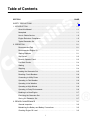
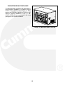
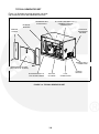
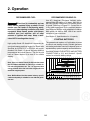
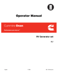
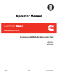
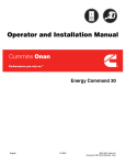
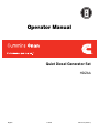
Operator Manual
Quiet Diesel Generator Set
HDZAA
English
9−2009
983−0103 (Issue 4)
California
Proposition 65 Warning
Diesel engine exhaust and some of its constituents are known
to the State of California to cause cancer, birth defects, and
other reproductive harm.
diesel warnings
Table of Contents
SECTION
PAGE
SAFETY PRECAUTIONS . . . . . . . . . . . . . . . . . . . . . . . . . . . . . . . . . . . . . . . . . . . . . . . . . . . . .
iii
1. INTRODUCTION . . . . . . . . . . . . . . . . . . . . . . . . . . . . . . . . . . . . . . . . . . . . . . . . . . . . . . . . . .
1-1
About this Manual . . . . . . . . . . . . . . . . . . . . . . . . . . . . . . . . . . . . . . . . . . . . . . . . . . . . .
1-1
Nameplate . . . . . . . . . . . . . . . . . . . . . . . . . . . . . . . . . . . . . . . . . . . . . . . . . . . . . . . . . . .
1-1
How to Obtain Service . . . . . . . . . . . . . . . . . . . . . . . . . . . . . . . . . . . . . . . . . . . . . . . . .
1-2
Engine Emissions Compliance . . . . . . . . . . . . . . . . . . . . . . . . . . . . . . . . . . . . . . . . . .
1-3
Typical Generator Set . . . . . . . . . . . . . . . . . . . . . . . . . . . . . . . . . . . . . . . . . . . . . . . . .
1-4
2. OPERATION . . . . . . . . . . . . . . . . . . . . . . . . . . . . . . . . . . . . . . . . . . . . . . . . . . . . . . . . . . . . . .
2-1
Recommended Fuel . . . . . . . . . . . . . . . . . . . . . . . . . . . . . . . . . . . . . . . . . . . . . . . . . . .
2-1
Recommended Engine Oil . . . . . . . . . . . . . . . . . . . . . . . . . . . . . . . . . . . . . . . . . . . . .
2-1
Starting Batteries . . . . . . . . . . . . . . . . . . . . . . . . . . . . . . . . . . . . . . . . . . . . . . . . . . . . .
2-1
Stop Switch . . . . . . . . . . . . . . . . . . . . . . . . . . . . . . . . . . . . . . . . . . . . . . . . . . . . . . . . . .
2-2
Remote Operator Panel . . . . . . . . . . . . . . . . . . . . . . . . . . . . . . . . . . . . . . . . . . . . . . . .
2-3
Pre-Start Checks . . . . . . . . . . . . . . . . . . . . . . . . . . . . . . . . . . . . . . . . . . . . . . . . . . . . . .
2-4
Starting . . . . . . . . . . . . . . . . . . . . . . . . . . . . . . . . . . . . . . . . . . . . . . . . . . . . . . . . . . . . . .
2-4
Stopping . . . . . . . . . . . . . . . . . . . . . . . . . . . . . . . . . . . . . . . . . . . . . . . . . . . . . . . . . . . . .
2-4
Loading the Generator Set . . . . . . . . . . . . . . . . . . . . . . . . . . . . . . . . . . . . . . . . . . . . .
2-5
Resetting Circuit Breakers . . . . . . . . . . . . . . . . . . . . . . . . . . . . . . . . . . . . . . . . . . . . . .
2-6
Connecting to Utility Power . . . . . . . . . . . . . . . . . . . . . . . . . . . . . . . . . . . . . . . . . . . . .
2-6
Operating in Cold Weather . . . . . . . . . . . . . . . . . . . . . . . . . . . . . . . . . . . . . . . . . . . . .
2-6
Operating in Hot Weather . . . . . . . . . . . . . . . . . . . . . . . . . . . . . . . . . . . . . . . . . . . . . .
2-6
Operating at High Altitude . . . . . . . . . . . . . . . . . . . . . . . . . . . . . . . . . . . . . . . . . . . . . .
2-6
Operating in Dusty Environments . . . . . . . . . . . . . . . . . . . . . . . . . . . . . . . . . . . . . . .
2-6
Breaking In a New Engine . . . . . . . . . . . . . . . . . . . . . . . . . . . . . . . . . . . . . . . . . . . . . .
2-7
Exercising the Generator Set . . . . . . . . . . . . . . . . . . . . . . . . . . . . . . . . . . . . . . . . . . .
2-7
Storing the Generator Set . . . . . . . . . . . . . . . . . . . . . . . . . . . . . . . . . . . . . . . . . . . . . .
2-7
3. PERIODIC MAINTENANCE . . . . . . . . . . . . . . . . . . . . . . . . . . . . . . . . . . . . . . . . . . . . . . . .
3-1
General Inspection . . . . . . . . . . . . . . . . . . . . . . . . . . . . . . . . . . . . . . . . . . . . . . . . . . . .
3-2
Maintaining the Battery and Battery Connections . . . . . . . . . . . . . . . . . . . . . . . . . .
3-2
Checking Engine Oil Level . . . . . . . . . . . . . . . . . . . . . . . . . . . . . . . . . . . . . . . . . . . . .
3-3
i
Changing Engine Oil . . . . . . . . . . . . . . . . . . . . . . . . . . . . . . . . . . . . . . . . . . . . . . . . . .
3-4
Cleaning the Engine Oil Strainer . . . . . . . . . . . . . . . . . . . . . . . . . . . . . . . . . . . . . . . .
3-5
Replacing the Air Filter Element . . . . . . . . . . . . . . . . . . . . . . . . . . . . . . . . . . . . . . . . .
3-6
Cleaning the Spark Arrestor . . . . . . . . . . . . . . . . . . . . . . . . . . . . . . . . . . . . . . . . . . . .
3-7
Replacing the Fuel Filter . . . . . . . . . . . . . . . . . . . . . . . . . . . . . . . . . . . . . . . . . . . . . . .
3-8
4. TROUBLESHOOTING . . . . . . . . . . . . . . . . . . . . . . . . . . . . . . . . . . . . . . . . . . . . . . . . . . . . .
4-1
Status Messages . . . . . . . . . . . . . . . . . . . . . . . . . . . . . . . . . . . . . . . . . . . . . . . . . . . . .
4-1
Maintenance Messages . . . . . . . . . . . . . . . . . . . . . . . . . . . . . . . . . . . . . . . . . . . . . . . .
4-1
Warning Messages . . . . . . . . . . . . . . . . . . . . . . . . . . . . . . . . . . . . . . . . . . . . . . . . . . . .
4-1
Fault Messages . . . . . . . . . . . . . . . . . . . . . . . . . . . . . . . . . . . . . . . . . . . . . . . . . . . . . . .
4-1
Symptom Diagnostics . . . . . . . . . . . . . . . . . . . . . . . . . . . . . . . . . . . . . . . . . . . . . . . . . .
4-2
5. SPECIFICATIONS . . . . . . . . . . . . . . . . . . . . . . . . . . . . . . . . . . . . . . . . . . . . . . . . . . . . . . . . .
5-1
Load on engine . . . . . . . . . . . . . . . . . . . . . . . . . . . . . . . . . . . . . . . . . . . . . . . . . . . . . . .
5-1
6. MAINTENANCE RECORD . . . . . . . . . . . . . . . . . . . . . . . . . . . . . . . . . . . . . . . . . . . . . . . . .
6-3
ii
SAFETY PRECAUTIONS
• Engine cooling air must not be used for heating the vehicle.
Thoroughly read the OPERATOR’S MANUAL
before operating the generator set. Safe operation and top performance can only be obtained when equipment is properly operated
and maintained.
GENERATOR VOLTAGE IS DEADLY
The following symbols in this manual alert you to
potential hazards to the operator, service person
and equipment.
• Disable the automatic genset feature (AGS)
of an inverter−charger or other automatic
starting device before servicing the genset to
avoid electric shock from an unexpected
start.
alerts you to an immediate hazard
that will result in severe personal injury or
death.
• Generator electrical output connections must
be made by a trained and experienced electrician in accordance with applicable codes.
alerts you to a hazard or unsafe
practice that can result in severe personal injury or death.
• The generator set must not be connected to
shore power (utility). Back-feed to shore power can cause electrocution and damage to
equipment. An approved switching device
must be used to prevent interconnections.
DANGER
WARNING
alerts you to a hazard or unsafe
practice that can result in personal injury or
equipment damage.
CAUTION
• Use caution when working on live electrical
equipment. Remove jewelry, make sure
clothing and shoes are dry, stand on a dry
wooden platform or rubber insulating mat and
use tools with insulated handles.
When equipped with an integral or add−on Automatic Generator Starting System (AGS) control,
exhaust carbon monoxide (CO), electric shock,
and moving parts hazards are possible due to unexpected starting. Turn off AGS whenever performing maintenance or service, when the vehicle
is stored between uses, is awaiting service, or is
parked in a garage or other confined area.
DIESEL FUEL IS COMBUSTIBLE
• Do not smoke or turn electrical switches ON
or OFF where fuel fumes are present or in
areas sharing ventilation with fuel tanks or
equipment. Keep flames, sparks, pilot lights,
arc-producing equipment and all other
sources of ignition well away.
ENGINE EXHAUST IS DEADLY
• Fuel lines must be secured, free of leaks and
separated or shielded from electrical wiring.
• Inspect for exhaust leaks at every startup and
after every eight hours of running.
MOVING PARTS CAN CAUSE SEVERE
PERSONAL INJURY OR DEATH
• Learn the symptoms of carbon monoxide poisoning in the generator set Operator’s Manual.
• Never sleep in the vehicle while the generator
set is running unless the vehicle is equipped
with a working carbon monoxide detector.
• Disable the automatic genset starting feature
(AGS) of an inverter−charger or other automatic starting device before servicing the
genset to avoid unexpected starting.
• Do not operate the generator set when the
vehicle is parked in a confined space, such as
a garage.
• Do not wear loose clothing or jewelry near
moving parts such as fans and other moving
parts.
• Keep hands away from moving parts.
• The exhaust system must be installed in accordance with the generator set Installation
Manual.
• Keep guards in place over fans and other
moving parts.
iii
BATTERY GAS IS EXPLOSIVE
the batteries to prevent starting during maintenance and service. (Always disconnect
negative [−] first and reconnect last to prevent
sparks between tools and vehicle frame.)
• Wear safety glasses.
• Do not smoke.
• To reduce arcing when disconnecting or reconnecting battery cables, always disconnect the negative (−) battery cable first and
reconnect it last.
• Keep the generator set and its compartment
clean. Excess oil and oily rags can catch fire.
Dirt and gear stowed in the compartment can
restrict cooling air.
FLAMMABLE VAPORS CAN BE IGNITED
BY OPERATION OF COACH ELECTRICAL
SYSTEMS AND CAUSE DIESEL ENGINES
TO OVERSPEED
• Make sure all fasteners are secure and
torqued properly.
• Do not work on the generator set when mentally or physically fatigued or after consuming
alcohol or drugs.
• Stop the generator set before fueling the
coach to reduce the risk of igniting flammable
vapors.
• You must be trained and experienced to
make adjustments while the generator set is
running—hot, moving or electrically live parts
can cause severe personal injury or death.
• Do not operate the diesel-powered generator
set where there are or can be flammable vapors created by fuel spills, gas leaks, etc.
Flammable vapors drawn into a diesel engine
air intake system can cause the engine to
overspeed, which can result in fire, explosion
and equipment damage. The owners and operators of the generator set are solely responsible for safe operation.
• Used engine oil has been identified by some
U. S. state and federal agencies as causing
cancer or reproductive toxicity. Do not ingest,
inhale, or contact used oil or its vapors.
• Do not use evaporative starting fluids. They
are highly explosive.
• Keep multi-class ABC fire extinguishers
readily at hand. Class A fires involve ordinary
combustible materials such as wood and
cloth. Class B fires involve combustible and
flammable liquids and gaseous fuels.
Class C fires involve live electrical equipment. See NFPA No. 10 (Portable Fire Extinguishers) or equivalent—BS EN 3-7:2004.
• To prevent accidental or remote starting while
working on the generator set, press the Stop
button and disconnect the battery cables at
• Generator set installation and operation must
comply with all applicable local, state and federal codes and regulations.
GENERAL PRECAUTIONS
• Keep children away from the generator set.
iv
1. Introduction
ABOUT THIS MANUAL
This is the Operator Manual for the generator sets
listed on the front cover. Read and carefully observe
all of the instructions and precautions in this manual. Keep this manual with the vehicle.
The following sections, Operation, Periodic Maintenance and Troubleshooting provide the instructions
necessary for operating the generator set and maintaining top performance. The owner is responsible
for performing maintenance in accordance with the
PERIODIC MAINTENANCE SCHEDULE (p. 3-1).
WARNING This generator set is not a life support system. It can stop without warning. Children, persons with physical or mental limitations, and pets could suffer personal injury or
death. A personal attendant, redundant power
or alarm system must be used if generator set
operation is critical.
Improper service or replacement of
parts can lead to severe personal injury or death
and damage to equipment and property. Service
personnel must be qualified to perform electrical and mechanical service.
WARNING
Unauthorized modifications or replacement of
fuel, exhaust, air intake or speed control system
components that affect engine emissions are
prohibited by law in the State of California.
NAMEPLATE
Be ready to provide the generator set model and serial numbers on the nameplate when contacting
Cummins Onan for parts, service or information.
Figure 1-1 illustrates typical model and serial numbers.
FIGURE 1-1. TYPICAL NAMEPLATE
Record the numbers on your generator set nameplate in Figure 1-2 so that they are easy to find when
needed. Each character in these numbers is significant. The last character of the model number is the
specification letter, which is important for obtaining
the right parts. Genuine Cummins Onan replacement parts are recommended for best results. Refer
to the generator set Parts Catalog.
FIGURE 1-2. RECORD NUMBERS HERE
1-1
HOW TO OBTAIN SERVICE
Call the nearest authorized Cummins Onan distributor for service, parts and product literature (such as
the generator set Service Manual or Parts Catalog).
Factory-trained representatives will handle your requests for generator set parts and service.
In North America
Call 1−800−888−6626 to contact the nearest Cummins Onan distributor in the United States or Canada. (This automated service utilizes touch-tone
phones only).
If you are unable to contact a distributor using the
automated service, consult the Yellow Pages. Typically, our distributors are listed under:
at the nearest Cummins Onan distributor for assistance.
Outside North America
Call Cummins Onan at 1−763−574−5000 from
7:30 AM to 4:00 PM, Central Standard Time,
Monday through Friday, or fax 1−763−528−7229.
Worldwide
Go to internet site www.cumminsonan.com for
Cummins Onan distributor contact information.
Information to Have Ready
Before calling for service, have the following information available:
GENERATORS − ELECTRIC,
ENGINES − GASOLINE OR DIESEL, or
RECREATIONAL VEHICLES − EQUIPMENT,
PARTS AND SERVICE.
1. The complete generator set model number and
serial number. See About This Manual
(Page 1-1).
If you have difficulty in arranging service or resolving a problem, please contact the Service Manager
3. The nature of the problem. See Section 4. Troubleshooting.
2. The date of purchase
1-2
ENGINE EMISSIONS COMPLIANCE
The label that states compliance with applicable engine emissions regulations is located on the air
cleaner cover as shown circled in Figure 1-3. Refer
also to the FEDERAL EMISSION DESIGN AND
DEFECT LIMITED WARRANTY FOR C. I. ENGINES (DIESELS) that was shipped in the same
package as the Operator’s Manual.
FIGURE 1-3. EMISSIONS LABEL LOCATION
1-3
TYPICAL GENERATOR SET
Figure 1-4 illustrates a typical generator set showing connection points and maintenance access.
INTERNAL
MUFFLER
GENERATOR SET
STOP SWITCH
AC OUTPUT, BATTERY POS (+)
& REMOTE CONTROL
CONNECTIONS
COOLING &
VENTILATING
AIR INLET
SERVICE
ACCESS
BATTERY NEG (−)
CONNECTION
MAINTENANCE ACCESS
(AIR, FUEL & OIL FILTERS)
BOTTOM EXHAUST &
HOT AIR DISCHARGE
BOTTOM
OIL DRAIN
FUEL
CONNECTIONS
FIGURE 1-4. TYPICAL GENERATOR SET
1-4
CHASSIS
GROUND
THIS PAGE LEFT INTENTIONALLY BLANK
1-5
2. Operation
RECOMMENDED FUEL
Diesel fuel is combustible and can
cause severe personal injury or death. Do not
smoke near fuel tanks or fuel-burning equipment or in areas sharing ventilation with such
equipment. Keep flames, sparks, pilot flames,
electrical arcs and switches and all other
sources of ignition well away. Keep a multiclass ABC fire extinguisher handy.
WARNING
High quality Grade 2-D diesel fuel is necessary for
good performance and long engine life. Diesel fuels
specified by ASTM D975 or EN 590 are recommended. Use Grade 1-D diesel fuel when ambient
temperatures are below freezing. The fuel should
have a Cetane number of at least 45 for reliable
starting.
RECOMMENDED ENGINE OIL
Use API (American Petroleum Institute) performance Class CF engine oil or better. Also look for
the SAE (Society of Automotive Engineers) viscosity grade. Referring to Figure 2-1, choose the viscosity grade appropriate for the ambient temperatures expected until the next scheduled oil change.
Multi-grade oils such as SAE 15W-40 are recommended for year-round use.
See Section 5. Specifications for oil capacity.
STARTING BATTERIES
The generator set requires a 12 volt battery to power
its control and starting circuits. Reliable generator
set starting and starter service life depend upon adequate battery system capacity and maintenance.
See MAINTAINING THE BATTERY AND BATTERY
CONNECTIONS (p. 3-2) and Section 5. Specifications for minimum battery ratings.
Note: Ultra Low Sulfur Diesel (ULSD) fuel that meets
the ASTM D975 standard for lubricity is suitable for
use with this generator set. The 1 to 2 percent less
energy content of the fuel can have a slight effect on
maximum engine power.
Note: B5 Bio-Diesel fuel that meets industry specifications and quality is suitable for use with this generator set.
FIGURE 2-1. OIL VISCOSITY VS. TEMPERATURE
2-1
STOP SWITCH
Press the stop switch (Figure 2-2) to stop the generator set or to prevent it from starting while performing maintenance and service. To allow the generator set to run, press the switch again. The switch
must stay in its “1” position for the generator set to
run.
Note: This is not a start switch. The generator set can
only be started using the remote operator panel
(p. 2-3).
FIGURE 2-2. STOP SWITCH
2-2
REMOTE OPERATOR PANEL
The remote operator panel (Figure 2-3) has the following features:
Display ON / Gen OFF Button − Press this button
to wake the generator set and display screen prior to
pressing the START button. This also starts the fuel
pump, which will prime the fuel system for five minutes if the generator set does not start.
Press this button to stop the generator set.
START Button − To start the generator set, press
and hold this button when “GEN OFF” appears on
the display screen after having pressed the Display
ON button.
Display Screen − The display screen displays generator set status, battery voltage, hours run and
warning and shutdown messages (see Section 4.
Troubleshooting).
Low Oil Indicator Light − This light warns that engine oil pressure is low or temperature is too high.
FIGURE 2-3. OPERATOR PANEL
2-3
WARNING
remove any objects blocking the air inlet or air
outlet.
EXHAUST GAS is deadly. All en-
gine exhaust contains carbon monoxide; an
odorless, colorless, poisonous gas that can
cause unconsciousness and death. Symptoms
of carbon monoxide poisoning include:
• Dizziness
• Nausea
• Vomiting
4. Turn off air conditioners and other large appliances.
STARTING
• Headache
• Weakness and Sleepiness
• Inability to Think Coherently
1. Perform the PRE-START CHECKS.
IF YOU EXPERIENCE ANY OF THESE SYMPTOMS, GET INTO FRESH AIR IMMEDIATELY. If
symptoms persist, seek medical attention. Shut
down the generator set and do not operate it until it has been inspected and repaired.
2. Start the generator set at the remote operator
panel.
A. Press and release the Display ON button.
B. Wait for “GEN OFF” to appear. If the generator set ran out of fuel and it is necessary
to prime the fuel system, wait at least one
minute before pressing the START button
to allow the fuel pump to prime fuel.
Never sleep in the vehicle while the generator
set is running unless the vehicle has a working
carbon monoxide detector. The exhaust system
must be installed in accordance with the generator set Installation Manual. Make sure there is
ample fresh air when operating the generator
set in a confined area.
C. Press and hold the START button until the
generator set starts. The generator set will
make up to three attempts to start. “GEN
ON” will appear on the display screen
when the generator set starts. “GEN
WAIT” will appear during rest periods between start attempts.
PRE-START CHECKS
Before the first start of the day and after every eight
hours of operation, inspect the generator set as
instructed under GENERAL INSPECTION (p. 3-2).
Keep a log of maintenance and the hours run and
perform any maintenance that may be due. See Returning the Generator Set to Service (p. 2-7) if the
vehicle has been in storage.
3. Press the GEN OFF button to reset the control
if the generator set does not start after three attempts. See Section 4. Troubleshooting if the
generator set still does not start.
4. Let the generator set warm up a few minutes
until it is running smoothly before connecting
the vehicle electrical loads (appliances).
Before each start:
1. Make sure all vehicle carbon monoxide (CO)
detectors are working.
5. Check for fuel, oil and exhaust leaks. Stop the
generator set immediately if there is leak and
have it repaired.
2. Check for fuel and oil leaks and damage to the
exhaust system.
3. To prevent overheating and to reduce fouling
with dust and debris, make sure the generator
set’s normal ground clearance is not being reduced by sloping ground, curbs, logs or other
objects. Repark the vehicle if necessary and/or
STOPPING
Run the generator set under no load for a few minutes to allow the engine to cool down and then press
and release the Gen OFF button.
2-4
LOADING THE GENERATOR SET
The generator set can power AC motors, air conditioners, AC/DC converters, battery chargers and
other appliances. How much appliance load* can be
powered depends upon the generator set power rating. The generator set will shut down if the sum of
the loads exceeds generator set power. See Section 4. Troubleshooting.
To avoid overloading the generator set and causing
shutdowns, compare the sum of the loads of the appliances that are likely to be used at the same time to
the power rating of the generator set. It may be necessary to run fewer appliances at the same
time—the sum of the loads must not be greater
than generator set rating.
The generator set may shut down due to overload
when a large motor or air conditioner is started or
cycles off and then on again, even though the sum of
the loads is less than generator set rating. The reason for this is that a motor’s startup load is much
larger than its running load. It may be necessary to
run fewer appliances when large motors and air
conditioners are cycling on and off.
TABLE 2-1. TYPICAL APPLIANCE LOADS
Load (watts)
Appliance
Air Conditioner
1400-2000
Battery Charger
Up to 3600
DC Converter
300-900
Refrigerator
600-1000
Microwave Oven
1000-1500
Electric Frying Pan or Wok
1000-1500
Electric Stove Element
350-1000
Electric Water Heater
1000-1500
Electric Iron
500-1200
Electric Hair Dryer
800-1500
Coffee Percolator
550-750
Television
200-600
Radio
50-200
Electric Drill
250-750
Electric Broom
200-500
Electric Blanket
50-200
Maximum power decreases as altitude increases
because air density decreases. For every 1000-foot
(305 m) increase in elevation you can expect power
to decrease approximately 3.5 percent. It may be
necessary to run fewer appliances at higher altitudes.
TABLE 2-2. POWER VS. ALTITUDE
Altitude
(Elevation above Sea Level)
Maximum Power
at/below 500 ft (152 m)
3200 W (rated)
at 2500 ft (762 m)
2980 W
at 5500 ft (1676 m)
2640 W
above 5500 ft (1676 m)
2640 W minus 112 W every 1000 ft (305 m)
* Appliance load and generator set power are measured in terms of watts (W) or kilowatts (kW), where 1 kilowatt (kW) = 1000 watts (W).
2-5
RESETTING CIRCUIT BREAKERS
OPERATING IN COLD WEATHER
Note: The generator set does not have a power output circuit breaker.
Make sure the engine oil viscosity is appropriate for
the cold ambient temperatures. See ENGINE OIL
RECOMMENDATIONS (p. 2-1). Be sure to
change the oil if a sudden drop in temperature occurs.
If a circuit breaker in the main power distribution
panel of the vehicle trips, either a circuit shorted or
too many appliances were running.
If a circuit breaker trips, disconnect or turn off as
many loads as possible and reset the circuit breaker. (Push the circuit breaker to OFF to reset it and
then to ON to reconnect the circuit.) If the circuit
breaker trips right away, either the electrical distribution system has a short or the circuit breaker is
faulty. Call a qualified electrician.
OPERATING IN HOT WEATHER
Pay particular attention to the following items when
operating the generator set in hot weather:
1. Make sure nothing blocks airflow to and from
the generator set.
2. Make sure the engine oil viscosity is appropriate for the hot ambient temperatures. See ENGINE OIL RECOMMENDATIONS (p. 2-1).
If the circuit breaker does not trip right away, reconnect the appliances, one by one, up to a total load
that does not overload the generator set.
3. Keep the generator set clean.
Electrical appliances and tools must be used and
maintained properly and be properly grounded to
cause the line circuit breakers to trip when short circuits occur.
Short circuits in electrical appliances and tools can cause fire and electrical
shock leading to severe personal injury or
death. Read and follow the equipment and tool
manufacturer’s instructions and warnings regarding use, maintenance and proper grounding.
4. Perform maintenance due. See PERIODIC
MAINTENANCE SCHEDULE (p. 3-1).
OPERATING AT HIGH ALTITUDE
WARNING
CONNECTING TO UTILITY POWER
For the effect of altitude on maximum power, see
LOADING THE GENERATOR SET (p. 2-5).
OPERATING IN DUSTY ENVIRONMENTS
Pay particular attention to the following items when
operating the generator set in dusty environments:
1. Do not let dirt and debris accumulate inside the
generator set compartment. Keep the generator set clean.
A vehicle with provisions for connecting utility power
must have an approved device to keep the generator set and utility from being interconnected. See the
generator set Installation Manual for more information.
2. Perform air cleaner maintenance more often.
See PERIODIC MAINTENANCE SCHEDULE
(p. 3-1).
WARNING Interconnecting the generator set
and the public utility can lead to electrocution of
utility line workers, equipment damage and fire.
Use an approved switching device to prevent interconnections.
3. Change engine oil more often. See PERIODIC
MAINTENANCE SCHEDULE (p. 3-1).
4. Keep containers of engine oil that have been
opened tightly closed to keep out dust.
2-6
BREAKING IN A NEW ENGINE
Proper engine break-in on a new generator set or on
one with a rebuilt engine is essential for top engine
performance and acceptable oil consumption. Do
not exceed 70 percent of rated power during the first
50 hours of operation. See LOADING THE GENERATOR SET (p. 2-5).
ator set cannot be exercised regularly and will be
idle for more than 120 days.
Storing the Generator Set
1. Change the engine oil and attach a tag indicating oil viscosity. See ENGINE OIL RECOMMENDATIONS (p. 2-1).
2. Disconnect the battery cables (negative [−]
cable first) from the starting battery and store
the battery according to the battery manufacturer’s recommendations. See MAINTAINING
THE BATTERY AND BATTERY CONNECTIONS (p. 3-2).
Proper engine oil and oil level are especially critical
during break-in because of the higher engine temperatures that can be expected. Change the oil if not
appropriate for the ambient temperatures during
break-in. See ENGINE OIL RECOMMENDATIONS
(p. 2-1). Change the oil after the first 50 hours of
operation.
3. Plug the exhaust tail pipe to keep out dirt, moisture, bugs, etc.
4. Close the fuel supply valve (if so equipped).
EXERCISING THE GENERATOR SET
Exercise the generator set at least 2 hours each
month if use is infrequent. Run the generator set at
approximately 1/2 rated power. See LOADING THE
GENERATOR SET (p. 2-5). A single two hour exercise period is better than several shorter periods.
Returning the Generator Set to Service
1. Check the oil tag on the generator set and
change the oil if the viscosity indicated is not
appropriate for the temperatures expected.
See ENGINE OIL RECOMMENDATIONS
(p. 2-1).
Exercising a generator set drives off moisture, re-lubricates the engine, replaces stale fuel and removes oxides from electrical contacts. The result is
better starting, more reliable operation and longer
engine life.
2. Reconnect the starting battery (negative [−]
cable last). See MAINTAINING THE BATTERY
AND BATTERY CONNECTIONS (p. 3-2).
3. Remove the plug from the exhaust tailpipe.
4. Change the air filter element if it is dirty (p. 3-6).
STORING THE GENERATOR SET
5. Open the fuel supply valve (if so equipped).
6. Inspect the generator set. See GENERAL INSPECTION (p. 3-2).
Proper storage is essential for preserving top generator set performance and reliability when the gener-
2-7
THIS PAGE LEFT INTENTIONALLY BLANK
2-8
3. Periodic Maintenance
Periodic maintenance is essential for top performance and long generator set life. Use Table 3-1 as
a guide for normal periodic maintenance. In hot and
dusty environments some maintenance procedures
should be performed more frequently, as indicated
by the footnotes in the table.
Maintenance, replacement or repair of emission
control devices and systems may be performed by
any engine repair establishment or individual. How-
ever, warranty work must be completed by an authorized Cummins Onan dealer.
WARNING Accidental or remote starting can
cause severe personal injury or death. Push the
Stop Switch Off and disconnect the battery
cables at the batteries to prevent starting during
maintenance and service. (Always disconnect
negative [−] first and reconnect last to prevent
sparks between tools and vehicle frame.)
TABLE 3-1. PERIODIC MAINTENANCE SCHEDULE
FREQUENCY
MAINTENANCE TASK
After First
50 Hrs
Every
Day
Every
Month
Every
250 Hrs
Every
500 Hrs
Every
Page
1000 Hrs
General Inspection
•
3-2
Check Engine Oil Level
•
3-3
Check Battery & Battery Connections1
Change Engine Oil1, 2, 3
3-2
•
•
Clean Spark Arrestor3
•
3-4
•
3-7
Replace Engine Air Filter2, 3
•
3-6
Replace Fuel Filter3
•
3-8
Adjust Engine Valve Lash4
•
−
Clean the Oil Filter
•
3-5
Check Fuel Injector Pressure4, 5
•
−
1.
2.
3.
4.
5.
Perform more often when operating in hot weather.
Perform more often when operating in dusty conditions.
Perform at least once a year.
Must be performed by trained and experienced personnel (authorized Cummins Onan service representatives).
EPA requirement.
3-1
GENERAL INSPECTION
Inspect the generator set before the first start of the
day and after every eight hours of operation.
Oil Level
Check engine oil level (Figure 3-1).
Exhaust System
EXHAUST GAS IS DEADLY! Do not
operate the generator set if there is an exhaust
leak or any danger of exhaust gases entering or
being drawn into the vehicle.
WARNING
Look and listen for exhaust system leaks while the
generator set is running. Shut down the generator
set if a leak is found and have it repaired before operating the generator set again.
Look for openings or holes between the generator
set compartment and vehicle cab or living space if
the generator set engine sounds louder than usual.
Have all such openings or holes closed off or sealed
to prevent exhaust gases from entering the vehicle.
Replace dented, bent or severely rusted sections of
the tailpipe and make sure the tailpipe extends at
least 1 inch (25.4 mm) beyond the perimeter of the
vehicle.
WARNING Do not park the vehicle in high grass
or brush. Contact with the exhaust system can
cause a fire.
Park the vehicle so that the generator set exhaust
gases can disperse away from the vehicle. Barriers
such as walls, snow banks, high grass and brush
and other vehicles can cause exhaust gases to accumulate in and around the vehicle.
Do not operate power ventilators or exhaust fans
while the vehicle is standing with the generator set
running. The ventilator or fan can draw exhaust
gases into the vehicle.
the fuel line is not rubbing against other parts. Replace worn or damaged fuel line parts before leaks
occur.
WARNING Diesel fuel leaks can lead to fire. Do
not operate the generator set if operation
causes fuel to leak.
Mechanical
Look for mechanical damage and listen for unusual
noises. Check the generator set mounting bolts.
To prevent overheating and to reduce fouling with
dust and debris, make sure the generator set’s normal ground clearance is not being reduced by sloping ground, curbs, logs or other objects. Repark the
vehicle if necessary and/or remove any objects
blocking the air inlet or air outlet.
MAINTAINING THE BATTERY AND
BATTERY CONNECTIONS
WARNING Flames, sparks and arcing at battery terminals, light switches and other equipment can ignite battery gas causing severe personal injury—Ventilate battery area before
working on or near battery—Wear safety
glasses—Do not smoke—Switch work light ON
or OFF away from battery—Stop generator set
and disconnect charger before disconnecting
battery cables—Disconnect negative (−) cable
first and reconnect last.
Refer to Table 3-1 for scheduled battery maintenance and follow the battery manufacturer’s instructions. If battery (DC) voltage is consistently low
or high, have the vehicle battery charging system
serviced. (The generator set does not recharge the
battery.) Always:
1. Keep the battery case and terminals clean and
dry and the terminals tight.
2. Use a battery terminal puller to remove the
cable clamps on post-type battery terminals.
3. Tighten threaded-stud battery terminals as recommended by the battery manufacturer.
Fuel System
4. Make sure which terminal is positive (+) and
which is negative (−) before making battery
connections, always removing the negative (−)
cable first and reconnecting it last to reduce
arcing.
Check for leaks at hose, tube and pipe fittings in the
fuel supply system while the generator set is running and while it is stopped. Check flexible fuel hose
sections for cuts, cracks, and abrasions. Make sure
3-2
CHECKING ENGINE OIL LEVEL
2. Pull out the oil dip stick, wipe it clean, reinsert
it and pull it out again to check the oil level (Figure 3-1).
State and federal agencies have determined that contact with used engine oil can
cause cancer or reproductive toxicity. Avoid
skin contact and breathing of vapors. Use rubber gloves and wash exposed skin.
WARNING
3. Add or drain oil as necessary. See RECOMMENDED ENGINE OIL (p. 2-1). Keep the
oil level between the MIN / MAX marks.
CAUTION Too much oil can cause high oil
consumption. Too little oil can cause severe
engine damage. Keep the oil level between
the MIN / MAX marks.
To check engine oil level:
1. Park the vehicle on level ground, shut down the
generator set and remove the front access
door.
4. Reinsert the dipstick and secure the oil fill cap
and front access door.
FIGURE 3-1. CHECKING ENGINE OIL LEVEL
3-3
CHANGING ENGINE OIL
1. Place a pail under the oil drain plug (Figure 3-2).
WARNING Accidental or remote starting can
cause severe personal injury or death. Push the
Stop Switch Off and disconnect the battery
cables at the batteries to prevent starting during
maintenance and service. (Always disconnect
negative [−] first and reconnect last to prevent
sparks between tools and vehicle frame.)
2. Remove the maintenance access door and the
oil fill cap, unscrew the oil drain cap and drain
all the oil from the engine. Reinstall the oil
drain cap securely.
3. Refill with approximately 0.7 quarts of oil, check
oil level (Figure 3-1) and secure the front access door.
4. Dispose of the used oil according to local environmental regulations.
Refer to Table 3-1 for scheduled engine oil change.
Change oil more often in hot and dusty environments. To change engine oil:
5. Secure the front access door.
FIGURE 3-2. CHANGING ENGINE OIL
3-4
CLEANING THE ENGINE OIL STRAINER
WARNING Accidental or remote starting can
cause severe personal injury or death. Push the
Stop Switch Off and disconnect the battery
cables at the batteries to prevent starting during
maintenance and service. (Always disconnect
negative [−] first and reconnect last to prevent
sparks between tools and vehicle frame.)
cessible through the front access door (Figure 3-3).
To replace the oil strainer:
1. Remove the maintenance access door.
2. Loosen the center screw of the strainer (about
five turns) and withdraw the strainer from the
engine block.
3. Use compressed air to clean the strainer. Blow
the debris from inside out.
WARNING Wear safety glasses when using
compressed air to clean the oil strainer to protect your eyes from severe injury from flying debris.
4. Replace the O-rings or strainer if damaged.
5. Lubricate the O-rings with clean oil and insert
the strainer until it stops.
6. Check for spring tension against the strainer
and tighten the center screw.
Refer to Table 3-1 for scheduled cleaning of the engine oil strainer. Clean the oil strainer more often in
hot and dusty environments. The oil strainer is ac-
7. Secure the front access door.
FIGURE 3-3. CLEANING ENGINE OIL STRAINER
3-5
REPLACING THE AIR FILTER ELEMENT
Accidental or remote starting can
cause severe personal injury or death. Push the
Stop Switch Off and disconnect the battery
cables at the batteries to prevent starting during
maintenance and service. (Always disconnect
negative [−] first and reconnect last to prevent
sparks between tools and vehicle frame.)
WARNING
ment. Replace it more often in dusty environments.
The air filter is accessible through the front access
door (Figure 3-4). To replace the air filter:
1. Remove the filter cover
2. Unscrew the the knurled nut and remove the
old filter element.
3. Clean dust and debris from the filter housing
and install the new filter element.
Refer to Table 3-1 for scheduled air filter replace-
4. Secure the front access door.
FIGURE 3-4. REPLACING THE AIR FILTER ELEMENT
3-6
CLEANING THE SPARK ARRESTOR
To clean the in-line tailpipe spark arrestor:
Refer to Table 3-1 for scheduled cleaning of the inline tail pipe spark arrestor canister (Figure 3-5),
which meets U.S. Forest Service requirements.
Cleaning is required for maximum generator set
performance.
1. Remove the cleanout plug on the side of the
spark arrestor canister.
2. Start the generator set and load it nearly to full
power. Let the generator set run for about five
minutes to expel the soot.
WARNING A hot muffler can cause severe
burns. Let the muffler cool down before removing or installing the cleanout plug.
3. Stop the generator set, allow the muffler to cool
down, and reinstall the cleanout plug.
FIGURE 3-5. TYPICAL LOCATION OF SPARK ARRESTOR IN TAILPIPE
3-7
REPLACING THE FUEL FILTER
See Table 3-1 for scheduled fuel filter replacement.
A dirty fuel filter may be the cause of a failure to start.
Diesel fuel is combustible and can
cause severe personal injury or death. Do not
smoke near diesel fuel tanks or equipment.
Keep flames, sparks, pilot lights, electrical
switches, arc-producing equipment and all other sources of ignition well away. Have a type
ABC fire extinguisher ready to use.
WARNING
Dirt can damage the fuel system.
Make sure to wipe dirt off the fuel hose fittings
before disconnecting.
CAUTION
The fuel filter is accessible through the front access
door (Figure 3-6). To replace the fuel filter:
1. Have paper towels or rags ready to clean the
two fuel hose fittings and absorb any fuel that
spills.
2. Clean the two fuel hose fittings to keep dirt from
entering the fuel hoses.
Close any fuel line shutoff valve before disconnecting the fuel line from the filter.
3. Loosen the two fuel hose clamps and the filter
body clamp and replace the filter element.
Make sure the arrow on the filter element points
up in the direction of fuel flow.
Accidental or remote starting can
cause severe personal injury or death. Push the
Stop Switch Off and disconnect the battery
cables at the batteries to prevent starting during
maintenance and service. (Always disconnect
negative [−] first and reconnect last to prevent
sparks between tools and vehicle frame.)
WARNING
4. Dispose of the fuel filter and paper towels or
rags in accordance with local environmental
regulations.
5. Secure the front access door.
FIGURE 3-6. FUEL FILTER
3-8
4. Troubleshooting
Note: Most generator set shutdowns and failures to
start can be avoided by performing periodic maintenance on schedule (TABLE 3-1. PERIODIC MAINTENANCE SCHEDULE) and by making sure that the
generator set does not run out of fuel. In this regard it
should also be noted that the vehicle manufacturer
has probably arranged the fuel tank dip tubes such
that the generator set will run out of fuel before the
fuel gauge reads EMPTY, thus reserving fuel for the
propulsion engine.
STATUS MESSAGES
The Operator Panel displays the following status
and periodic maintenance messages. Warning and
Fault messages, once cleared, cannot be retrieved.
To clear faults turn display off/on.
Note: Operator warning and fault messages, once
cleared, cannot be retrieved.
GEN OFF Indicates that the generator set is off but
ready to start.
GEN ON Indicates that the generator set is running.
GEN START If this message appears while pressing START, but the engine does not crank, check the
stop switch inside the generator set (p. 2-2) and
push it on.
GEN CAL This message appears during generator
set start-up indicating that it is in calibration mode
and not yet ready to produce AC output voltage.
Wait a few seconds.
RESTART GEN? This message appears any time
the generator set stops. Turn off and restart the generator set.
MAINTENANCE MESSAGES
OIL CHANGE / CHECK OIL LEVEL These messages appear every time the generator set hour
counter reaches preset oil check/change intervals
(change after first 50 hours and then every 250
hours). The generator set continues to run. Fill or
change oil as necessary. The generator set must be
running to reset the message. Hold START until the
message clears. If not reset, the message will reappear after an hour of running.
WARNING MESSAGES
SHORT CIRCUIT A connected appliance probably
has a short circuit. AC output voltage is turned off
but the engine is kept running to cool the generator
set. Disconnect all appliances, press STOP to stop
the engine and then restart the generator set. Reconnect appliances one by one to find out which one
shorted and have it repaired or replaced.
FAULT MESSAGES
OIL TEMP-PRESS
Possible Cause: The engine lubricating oil temperature is too high or the pressure is too low. The oil
pressure and temperature switches are connected
in parallel. When the engine is at rest and cold, the
pressure switch is closed and the temperature
switch is open.
Diagnosis/Repair—Low Oil Pressure:
1. Check Oil level and refill as necessary.
Diagnosis/Repair—High Oil Temperature:
GENERATOR ALERT
Possible Cause There are three possible causes:
1. The Operator Panel in the vehicle must be able
to communicate with the inverter in the generator set. If communication is interrupted this fault
will likely occur when attempting to start the
generator set.
GEN WAIT The generator set is delaying the next
start attempt to allow the starter motor to cool down.
Or, more time is being allowed for engine preheating
because the ambient temperature is below freezing.
Try restarting when the message turns off.
2. Without power from the PMA auxiliary windings
AC3 and AC4, the inverter will not be able to
communicate with the Operator Panel. If the
output frequency detected by the inverter is too
high (engine speed greater than 4200rpm) the
LOW BATTERY Battery voltage is below the minimum value (9 VDC) necessary to start the generator
set. Check battery connections and recharge or replace the battery.
4-1
inverter will shut down the generator set.
See PMA information in section 4−9 for engine
speed calculation.
3. Faulty inverter.
Always perform stator check before
replacing the invertor. Failure to do so will result
in damage to the inverter.
CAUTION
Always perform stator check before
replacing the invertor. Failure to do so will result
in damage to the inverter.
CAUTION
LOW ENGINE POWER
Possible Cause Engine speed is below 2300 rpm
Diagnosis/Repair:
1. Contact an authorized Cummins Onan dealer.
Diagnosis/Repair:
SYMPTOM DIAGNOSTICS
1. Contact an authorized Cummins Onan dealer.
Always perform stator check before
replacing the invertor. Failure to do so will result
in damage to the inverter.
CAUTION
DEAD OPERATOR PANEL
Possible Cause/Diagnosis/Repair
1. Contact an authorized Cummins Onan dealer.
OVER TEMPERATURE (INVERTER)
A. Replace the 30 amp fuse on the internal
control panel, if blown.
Possible Cause Inverter temperature detected to
be over 70° C.
B. Check for 12 VDC at Pin 3 of the 10-pin
connector on the internal control panel and
for a good ground at Pin 10.
Diagnosis/Repair:
1. Reduce loads.
C. Check for 12 VDC at Pins 2, 3 and 6 of the
9-pin connector on the internal control
panel and for a good ground at Pin 5 of the
6-pin connector.
Always perform stator check before
replacing the invertor. Failure to do so will result
in damage to the inverter.
CAUTION
D. Repair wiring and connectors as necessary.
OVERLOAD
Possible Cause Too many applications are connected, or the inverter is defective.
Diagnosis/Repair:
1. Measure current draw. If it is greater than 32
amps, reduce the number of appliances connected in the coach and wait a few minutes for
generator set to cool down. Press STOP to stop
engine and restart the generator set.
2. If the generator set shuts down on ’Overload’
condition, disconnect it from the coach and
bench-test with a load-bank. If the generator
set runs fine without shutting down, then the
problem likely exists within vehicle wiring and/
or appliances. In the event that it shuts down
with no load connected, perform checks in Step
3.
3. Ensure stator is not damaged and has no
shorts internally or to Ground on all Main and
Auxiliary Windings. Test winding insulation resistance with a Megger. Replace state if necessary. If the stator is good, replace the inverter.
ENGINE CRANKS BUT DOES NOT START
Note: The generator will make up to three start attempts, cranking each time for 5 seconds and pausing for 2 seconds if necessary before the next crank.
Gen Wait should appear on the display.
Possible Cause/Diagnosis/Repair
1. Clear the Gen Wait message from the Operator
Panel by cycling it off and on. Try starting again.
2. Check the fuel level and fill as necessary.
3. Press the stop switch (p. 2-2) if it is not in its “1”
position.
4. Replace the fuel if it is not of the specified grade
or suitable for the ambient temperature (p 2-1).
ENGINE SPITS/SPUTTERS/EXHAUSTS WHITE
SMOKE
Possible Cause/Diagnosis/Repair
1. Air in fuel system: Prime fuel system by turning
on the display, lift pump should run for 5 minutes to prime system. If problem goes away
4-2
check for air leaks with soapy water at fittings
and hoses.
ENGINE EXHAUSTS BLACK SMOKE
Possible Cause/Diagnosis/Repair
1. Contact an authorized Cummins Onan dealer.
ENGINE WON’T STOP
Possible Cause/Diagnosis/Repair
1. Contact an authorized Cummins Onan dealer.
ENGINE STOP
LEVER
FIGURE 4-1. ENGINE STOP LEVER
4-3
WIRING DIAGRAM . . . . . . . . . . . . . . . . . . . . . . . . . . . . . . . . . . . . . . . . . . . . . . . . . . . . . . . . . . A-1
4-4
5. Specifications
GENSET CONTROL: Integrated Microprocessor-Based Engine and Generator Controller and AC Output Inverter
GENERATOR: Three-Phase, Permanent Magnet, 3600 RPM
Power (@1.0 power factor)
Voltage
Frequency
Number of Phases
Current
See Nameplate
120
60 Hz
1
26.7 amps
FUEL CONSUMPTION:
@ 1 kW
@ 2 kW
@ 3 kW
@ 3.5 kW
0.20 gph (0.76 lph)
0.27 gph (1.03 lph)
0.36 gph (1.37 lph)
0.38 gph (1.44 lph)
ENGINE: Single-Cylinder, Direct-Injection, Air-Cooled, 4-Stroke Diesel
Bore
Stroke
Displacement
Compression Ratio
3.15 in (80 mm)
2.72 in (69 mm)
21 in3 (347 cc)
1:22
16°
2900±174 psi (200±12 bar)
290 to 319 psi (20 to 22 bar)
Fuel Injection Timing (BTDC)
Fuel Nozzle Injection Pressure
Cylinder Compression Test
0.004 in (0.1 mm)
1.1 quart (1.1 liter)
Valve Lash: Intake & Exhaust (cold)
Oil Capacity
DC SYSTEM:
12 volts
475 amps down to 0° F (−17° C)
650 amps down to −20° F (−29° C)
Nominal Battery Voltage
Minimum Battery Capacity
CCA (Cold Cranking Amps)
WEIGHT (WET): 205 lbs (93 kg)
SIZE (L x W x H): 30.17 x 17.3 x 18.02 in (766.4 x 439.4 x 457.7 cm)
SOUND LEVEL: 68 dB(A) @ 10 ft (3 meters)
quality. We therefore recommend a minimum
engine load of 15%.
LOAD ON ENGINE
• If operated at such low loads, it is best to operate the engine at a significantly higher load for
a short period before switching it off.
• Operating the engine for a lengthy period off−
load or at very low loads can affect its running
5-1
THIS PAGE LEFT INTENTIONALLY BLANK
5-2
6. Maintenance Record
Record all periodic and unscheduled maintenance and service. See Section 3. Periodic Maintenance.
DATE
HOUR
METER
READING
MAINTENANCE OR SERVICE PERFORMED
Record the name, address, and phone number of your authorized Cummins Onan service center.
6-1
THIS PAGE LEFT INTENTIONALLY BLANK
6-2
THIS PAGE LEFT INTENTIONALLY BLANK
Cummins Power Generation
1400 73rd Ave. NE
Minneapolis, MN 55432 USA
Phone 1 763 574 5000
Toll-free 1 800 888 6626
Fax 1 763 574 5298
Email www.cumminsonan.com/contact
www.cumminsonan.com
CumminsR, OnanR, the “C” logo, and “Performance you rely on.”
are trademarks of Cummins Inc.
E2009 Cummins Power Generation, Inc. All rights reserved.