1
Microtek ScanWizard Pro
Reference Manual
for Windows
i
Copyright 2005 by Microtek International, Inc.
All rights reserved.
Trademarks
Microtek®, ArtixTM, and ScanWizardTM Pro are trademarks or registered trademarks of Microtek International
Inc. Adobe® and Acrobat® are registered trademarks of Adobe Systems Incorporated. Macintosh® and Apple®
are registered trademarks of Apple Computer, Inc. Windows® is a registered trademark of Microsoft
Corporation. All other products or name brands are trademarks of their respective holders.
Important
Documents that you scan may be protected under copyright law. The unauthorized use of such documents
could be a violation of the rights of the copyright holder. Microtek bears no responsibility for the
unauthorized use of copyrighted materials.
To obtain optimal results from the Microtek scanning software and user's manual, you should be familiar with
such Windows concepts as pointing, clicking, dragging, and selecting from menus and dialog boxed. If these
things are new to you, refer to your Microsoft Windows User's Guide.
August 2005
Microtek Lab, Inc.
16941 Keegan Avenue, Carson, CA 90746
Main: 310-687-5800, Fax: 310-687-5950, http://www.microtekusa.com
Microtek International, Inc.
6, Industry East Road 3, Science Based Industrial Park, Hsinchu, 30077, Taiwan
Tel: 886-3-5772155, Fax: 886-3-5772598, http://www.microtek.com
ii
Contents
Reference
1
ScanWizard Pro for Windows ......................................................................................... 2
Bringing up the ScanWizard Pro for Windows ................................................................3
Exiting ScanWizard Pro .................................................................................................. 3
The Preview Window ..................................................................................................... 4
The Menu Bar ......................................................................................................... 5
The Scanner Menu .................................................................................................. 6
Scanner Model ................................................................................................ 6
TCP/IP Scanner Setup ....................................................................................... 7
Get Current Scanner Info ................................................................................ 9
Scanner Probe ................................................................................................. 9
Scanner Control (Power Saving Control) ........................................................ 10
The View Menu .................................................................................................... 11
Overview Image ............................................................................................. 11
Prescan Image ............................................................................................... 12
Resize Window to Fit ..................................................................................... 13
Bring Settings Window to Front ..................................................................... 14
Show/Hide commands ................................................................................... 14
Show/Hide All Tag Windows .......................................................................... 14
Show/Hide White/Black Markers ................................................................... 14
The Preferences Menu .......................................................................................... 15
Scan Material ................................................................................................. 16
The Scan Material Status icon ........................................................................ 17
Color Matching Setup .................................................................................... 18
Display using monitor compensation ....................................................... 18
Display ................................................................................................... 18
Native mode RGB color matching (Native Color Mode only) .................... 19
Embed ICC destination profile in scan image ........................................... 19
RGB Destination ..................................................................................... 19
CMYK Destination .................................................................................. 20
Add Profiles ............................................................................................ 20
Info ........................................................................................................ 21
Preview .................................................................................................. 21
Refresh ................................................................................................... 21
iii
White/Black Points Setup ............................................................................... 22
Auto Clipping ......................................................................................... 22
Output Levels ......................................................................................... 22
H/S Markers ........................................................................................... 23
Cursor Auxiliary Lines ................................................................................... 24
Overview Setup ............................................................................................. 26
Overview Area ......................................................................................... 26
Unit ......................................................................................................... 26
Fast Overview ......................................................................................... 27
Overview automatically when ScanWizard Pro is started ......................... 27
Keep Overview image ............................................................................. 27
Show confirmation message box if there is any prescan image ................. 27
Preview ................................................................................................... 27
Prescan Setup ................................................................................................ 28
Fast Prescan ........................................................................................... 28
Keep All prescan images .......................................................................... 28
Prescan Image Margin ............................................................................ 28
Prescan Image Dimension ....................................................................... 28
Background Prescan ............................................................................... 28
Monitor Gamma Setup ................................................................................... 29
Monitor Gamma ..................................................................................... 29
Invert ............................................................................................................ 30
More command ............................................................................................. 31
Smoked Glass Background ...................................................................... 31
Confirmation Message ............................................................................ 32
Color Space Mode .................................................................................. 32
Scan Mode ............................................................................................. 32
Best Quality: Multiple Sampling ................................................................ 33
Interpolation Mode ................................................................................ 33
Working Directory .................................................................................. 33
The Help Menu ..................................................................................................... 34
About ............................................................................................................ 34
The Tool Buttons .................................................................................................. 35
Scan Frame tool ............................................................................................. 36
Scan Frame Keyboard Shortcuts ............................................................. 37
Magnify Glass tool ......................................................................................... 39
Pane tool ....................................................................................................... 40
Dropper tool ................................................................................................. 41
iv
To create a Tag window ...........................................................................
To close the Tag window .........................................................................
Choosing Black and White Droppers .......................................................
Input display Mode switch ......................................................................
Black, White, and Color diamonds ..........................................................
Setting White/Black points ......................................................................
To restore original settings: .....................................................................
To change the sample size of the Dropper: ..............................................
To display color information for a pixel or an averaged area: ...................
Dropper Keyboard Shortcuts ..................................................................
Action Buttons ...............................................................................................
Rulers ............................................................................................................
Preview Area .................................................................................................
Auxiliary information .....................................................................................
Preview image resolution: .......................................................................
Zoom scale .............................................................................................
Zoom-out ...............................................................................................
Zoom-in ..................................................................................................
White/Dark points marker flasher ...........................................................
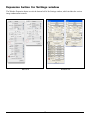
The Settings Window ........................................................................................
Output Image Parameters .....................................................................................
Type (Image Type or Scan Mode) ....................................................................
Palette ....................................................................................................
Dither .....................................................................................................
Resolution .....................................................................................................
Unit selection ................................................................................................
Image Dimension controls .............................................................................
Scan Frame (input) x Scaling = output .....................................................
Scan Frame .............................................................................................
Output ...................................................................................................
Scaling ....................................................................................................
Image Size ..............................................................................................
Unit of Measurement ..............................................................................
Keep Proportion .....................................................................................
Transform (Rotate and Flip tool) .............................................................
Advanced Image Correction Tools ........................................................................
Available Image Correction Effects .................................................................
Introducing the Image Correction tools .........................................................
v
41
42
42
42
42
43
43
44
44
44
45
46
47
48
48
48
48
48
48
49
50
50
51
51
52
53
54
54
54
54
55
55
55
55
55
57
57
58
Using the Advanced Image Correction dialog box ..........................................
The Action Buttons in the AIC dialog box .......................................................
1:1 Thumbnails .......................................................................................
Hide Thumbnails .....................................................................................
Preview ..................................................................................................
The OK button .......................................................................................
The Cancel button ..................................................................................
The Default button .................................................................................
The Revert button ...................................................................................
The Add to Menu button ........................................................................
To retrieve user-defined AIC settings .......................................................
The Reset button .....................................................................................
To remove user-defined AIC settings .......................................................
Dynamic Range tool .......................................................................................
The Dynamic Range dialog box ...............................................................
White/Black Points tool .................................................................................
The White/Black Points dialog box (Color/Gray image) ............................
The Threshold dialog box (Line-art image) ..............................................
Sharpen ..................................................................................................
Gradation Curve tool (LCH mode only) ..........................................................
How to read the curve ............................................................................
The Gradation Curve dialog box .............................................................
Color Cast tool (LCH Mode Only) ..................................................................
The Color Cast dialog box .......................................................................
Saturation tool (LCH Mode Only) ..................................................................
The Saturation dialog box .......................................................................
Selective Color Tool (LCH Mode Only) ...........................................................
The Selective Color dialog box ................................................................
Tone Curve tool .............................................................................................
The Tone Curve dialog box ......................................................................
Filter tool ......................................................................................................
The Filter dialog box ..............................................................................
Descreen .......................................................................................................
To use Descreen: .....................................................................................
Brightness and Contrast tool (Native Color Mode only) ..................................
Brightness ...............................................................................................
Contrast .................................................................................................
vi
58
59
59
59
59
60
60
60
60
60
61
61
62
63
64
66
66
68
68
69
69
71
74
74
76
76
77
77
82
82
84
84
88
88
89
89
89
Color Correction tool (Native Color Mode only) ............................................ 90
Color Wheel ........................................................................................... 90
Saturation bar ......................................................................................... 90
Using the Color Correction tool .............................................................. 91
The Information Window ............................................................................................ 92
Cursor Locator .............................................................................................. 93
Input value .................................................................................................... 93
Output value ................................................................................................. 93
Sample size button ......................................................................................... 94
Using the Pixel Display ................................................................................... 94
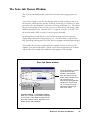
The Scan Job Queue Window ...................................................................................... 95
Multiple Selections ............................................................................................... 96
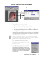
How to read the Scan Job window ........................................................................ 97
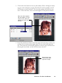
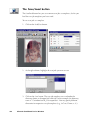
The New button .................................................................................................... 98
More on the New button ............................................................................. 102
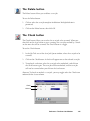
The Duplicate button .......................................................................................... 103
The Delete button ............................................................................................... 105
The Check button ............................................................................................... 105
The Save/Load button ......................................................................................... 106
New name auto given if the name already exists ........................................... 107
The Up/Down Position Arrows ........................................................................... 108
Scan to File
109
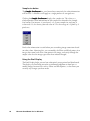
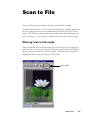
Entering Scan to File mode ......................................................................................... 109
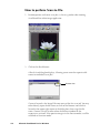
How to perform Scan-to-File ...................................................................................... 110
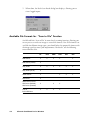
Available File Formats for “Scan to File” Function ......................................................112
Appendix
A-1
Appendix A: Product and Technical Support .............................................................. A-2
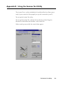
Appendix B: Using the Scanner Test Utility ................................................................. B-1
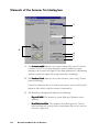
Elements of the Scanner Test dialog box ............................................................... B-2
How to use the Scanner Test utility ....................................................................... B-5
Appendix C: Kodak Color Management System .......................................................... C-1
KCMS Overview .................................................................................................. C-1
Some Background Information ..................................................................... C-1
The Idea Behind Color Management ............................................................. C-1
How Color Management Works ........................................................................... C-2
How CMS Translates between Devices ................................................................. C-3
vii
What are Device Color Profiles ............................................................................ C-4
Where Do Color Profiles Come From? .......................................................... C-4
A Word about Source and Destination .......................................................... C-5
Controlling UCR & GCR ...................................................................................... C-7
Controlling UCR and GCR with Professional CMYK Profiles ........................... C-7
Some Background ........................................................................................ C-7
UCR ............................................................................................................. C-8
Advantages & Disadvantages to UCR ............................................................ C-8
GCR ............................................................................................................. C-9
Advantages & Problems of GCR .................................................................... C-9
Professional CMYK Profiles Package .................................................................. C-10
What You Get with Professional CMYK Profiles Package ............................. C-10
EUROPEAN PRINTING STANDARDS: .......................................................... C-10
U.S. CMYK SWOP PRINTING STANDARDS: ................................................ C-11
JAPANESE PRINTING STANDARDS: ............................................................ C-11
Check With Your Service Provider ..................................................................... C-12
Colorant Laydown Order: Yellow, Magenta, Cyan, Black .............................. C-12
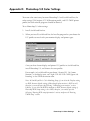
Appendix D: Photoshop 5.0 Color Settings ................................................................. D-1
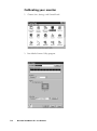
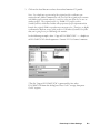
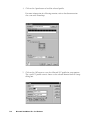
Calibrating your monitor ..................................................................................... D-2
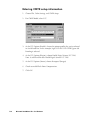
Entering RGB Setup information .......................................................................... D-5
Entering CMYK setup information ....................................................................... D-6
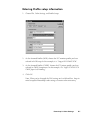
Entering Profile setup information ....................................................................... D-7
viii
Reference
This section is a listing of features found in the ScanWizard Pro for Windows
scanning software.
The reference information is organized in four parts, which shows the four
major windows of the program:
• Preview
• Settings
• Information
• Scan Job Queue
Reference: The Preview window
1
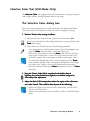
ScanWizard Pro for Windows
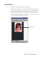
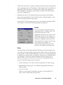
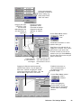
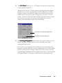
ScanWizard Pro for Windows consists of four major windows: Preview, Settings,
Information, and Scan Job.
The Preview and Settings windows appear automatically after the ScanWizard
Pro is started up. The Scan Job and Information windows appear when you
bring up ScanWizard Pro at the first time. You may hide or show them from the
View menu and click on the commands Show Scan Job Window and Show Info
Window.
Settings
window contains
scanning
parameters for
outputting the
image and
includes image
correction tools
Scan Job
window
provides key
functions in
managing
scan jobs
2
Microtek ScanWizard Pro for Windows
Information
window
provides
information
on the
Preview
image
Preview
window has
commands and
tools for
controlling the
scanner
Bringing up the ScanWizard Pro for Windows
Click Start, Programs, select Microtek ScanWizard Pro for Windows, then
Microtek ScanWizard Pro. Alternatively, you may start up your image-editing
software first. When the application opens, choose the command for acquiring
ScanWizard Pro.
The main screen will appear, but the very first time that ScanWizard Pro is
started up, the 4 windows will all appear.
The next time you start up ScanWizard Pro, the main screen will look exactly
like the last time you exited the software. This means that if you had all four
windows open the last time you quit ScanWizard Pro, the same four windows
will appear the next time you start it up.
Exiting ScanWizard Pro
To exit ScanWizard Pro for Windows, double click on the close box on the
upper left side of the Preview window.
Double-click
here to exit
ScanWizard Pro
Reference: The Preview window
3
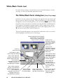
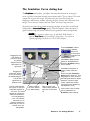
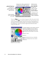
The Preview Window
The Preview window is the most prominent window of the four major windows,
and it includes the various commands and tools for controlling the scanner.
Elements of the Preview window
1
3
2
4
5
6
8
7
1
2
4
The Menu Bar includes the different menus
for setting up the scanner (Scanner menu),
controlling view options (View menu),
customizing the software (Preferences
menu), Image Correction function
(Correction menu), and accessing on-line
help (Help menu).
ool buttons simplify the performance
The T
Tool
of certain tasks. The Tool buttons are (left to
right) Frame, Magnify Glass, Pane, and
Dropper.
3
The Action buttons generate a specific
action from the scanning software. The
Action buttons include Overview, Prescan
and Batch/Scan.
4
The Scan Material Status icon shows your
scan material, whether it's reflective,
positive, or negative.
Microtek ScanWizard Pro for Windows
5
The Preview window is where the
Overview or Prescan image appears
after you click on the Overview or
Prescan button.
6
Rulers are located on both sides of the
window to help you with measurement
and alignment. The ruler unit can be
selected by clicking on the arrow at
the 0,0 point of the rulers.
7
The Status bar shows you some
information for easier operation.
8
The Auxiliary bar shows 1) The screen
resolution of the preview image. 2)
Zoom scale 3) Zoom out 4) Zoom in 5)
Black/white markers indicator
The Menu Bar
Reference: The Preview window
5
The Scanner Menu
The Scanner Menu lets you:
• Select your scanner model or select a shared scanner on the local area
network
• Set up TCP/IP scanners
• Get information about current scanner
• Probe both the local and network scanners
• Set idle time for saving power
Scanner Model
The top of the scanner menu displays all the scanners with their respective SCSI
IDs. The shown scanners are either your locally connected scanners or the
network scanners; the current scanner is indicated by a check.
Only one scanner can be accessed at a time. To switch among various scanners,
select the scanner to be used.
The scanner with its SCSI ID is
displayed. The current scanner is
marked by a check.
If you cannot locate a scanner for use, perform a new search for available
scanners. The next time you launch ScanWizard Pro, the connected scanners
will be available for choosing.
6
Microtek ScanWizard Pro for Windows
Some scanner models feature multiple scanning lenses (one for high-resolution
scanning and one for low-resolution scanning). If the multiple-lens scanner is
detected, a submenu appears for lens selection, and you can choose the option
you want.
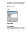
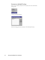
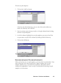
TCP/IP Scanner Setup
This window is the control panel for managing scanner servers. Choose the
“TCP/IP scanner setup” command from the Scanner menu; the following dialog
box appears.
Enable TCP/IP scanning
If checked, your computer is enabled to access remote scanners (scanner
servers) on the network. If unchecked, remote access is disabled.
Auto-search scanner servers
If checked, clicking the Test Connection button displays the IP addresses of
connected scanners. If unchecked, you can type either the host names or the
corresponding IP addresses in the Server Location edit box, then click the Test
Connection or OK button. The Test Connection button lists the information of
the detected scanner servers; while the OK button performs auto searching of
scanner servers without showing information on the detected scanners. The
detected scanners can be selected from the Scanner menu of the ScanWizard
Pro Overview window.
Reference: The Preview window
7
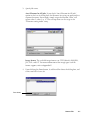
Server Location
When the “Auto-search scanner servers” option is checked, the Test Connection
window lists the detected computers with their corresponding scanner IP
addresses. If the option is unchecked, you can type the IP address or the host
computer names. In a local area network, each computer has a unique name for
identifying itself from the others.
Note: The IP address is identified by dot-segregated four-position numbers (e.g.,
172.16.17.135). The four number should be within 0 to 255. The left three numbers of
the connected scanner are the same, in other words, all of the connected scanners appear
as “172.16.17”, but the last number is unique to the respective scanner.
To know the name of the host computer:
• For Windows 95/98/Me users:
Right-click the Network Neighborhood on the Windows desktop; select
Properties
Properties, then click the Identification tab on the server station. The
computer name is shown.
• For Windows 2000/NT users:
Right-click the My Computer on the Windows desktop; select Properties
Properties,
then click the Network Identification tab on the server station. The
computer name is shown.
Server Port Number
In a local area network, all connected scanners should use the same server port
number; otherwise, the scanners cannot be found. The default and recommend
port number is 303.
Server Search Timeout Period
This edit box allows you to set the timeout period, after which the scanner
server stops its search. Use the up/down button to increase/decrease the
timeout period or input an acceptable period (1 to 60 seconds).
Test Connection
When you click on this button, based on the settings you have made on the TCP/
IP Scanner Setup window, ScanWizard Pro starts to probe the connected
scanner servers on the network, then lists the detected scanner servers in the
Test Connection window.
8
Microtek ScanWizard Pro for Windows
Get Current Scanner Info
This command provides information about your current scanner. When you
choose this command, a dialog box appears showing the scanner model, SCSI ID
number, and firmware version.
Scanner Probe
This command detects both the local and remote scanners on the network.
When scanners are detected, the window below appears.
To select a connected scanner for use, choose it from the Scanner menu of the
ScanWizard Pro Overview window. The selected scanner is shown with a check
mark.
Reference: The Preview window
9
Scanner Control
(Power Saving Control)
Not all Microtek scanner models support scanning lamp power saving feature. If
your Microtek scanner is implemented with this function, you can set the time
for scanning lamp time-out. By default, if the scanner is idled for 15 minutes, the
scanning lamp turns off. The power saving feature extends the service life of the
scanning lamp. To disable power saving function, uncheck the “Auto Power
Saving mode” lamp control check box.
Not all Microtek scanner models support Scanner Control function. If your
scanner is implemented with these functions.
10
Microtek ScanWizard Pro for Windows
The View Menu
The View menu lets you:
• Get an overview or prescan view of an image
• Resize the Preview window
• Show or hide the Information and Scan Job windows
• Show or hide Status Bar
Overview Image
This command switches to Overview mode, lets you view the Overview image
among the scan jobs.
The Overview is a preview of your image as defined by the parameters set in the
Overview Setup command (in the Preferences menu). For instance, if your image
is 8" x 5" but the dimensions in the Overview Setup are 4" x 3", your overview
will be 4" x 3".
The maximum size of the Overview varies, depending on your scanner model.
For example, if the scan bed (the glass surface) of your scanner has a maximum
size of 8.5" x 11", the maximum Overview will be limited to those dimensions.
The size of the Overview can be changed by setting new dimensions in the
Overview Setup command. The new dimensions will take effect, however, only
with the next Overview. This means you need to click on the Overview button so
that the scanner does a new Overview; only then will you see the new
dimensions of the Overview.
Reference: The Preview window
11
Prescan Image
By default, the Prescan Image Command does not exist, unless you press the
Prescan button. Each prescan image belongs to the respective scan job.
In the above screen, the Untitled 1 Prescan Image is resulted ever since you
clicked the Prescan button for a scan job named Untitled 1
When you select the prescan image item (e.g., Untitled 1 Prescan Image), the
preview window switches to the Prescan mode.
12
Microtek ScanWizard Pro for Windows
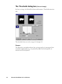
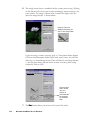
Resize Window to Fit
This command adjusts the Preview window to fit the Overview area.
In the example below, the Preview window is larger than the Overview area, as
denoted by the empty space below the vertical ruler. In other instances, the
Preview window may also exceed the Overview area if you manually enlarged
the Preview window (by dragging on the resize box).
To utilize window space more efficiently, use this command to resize the
Preview window.
Before resizing
After resizing
To use this feature:
Choose the command Resize Window to Fit in the View menu or enter “Ctrl+r”
key.
This command is available only if the current zoom level is 100%, and is disabled
if zoom is set to other levels.
Reference: The Preview window
13
Bring Settings Window to Front
This command brings the Settings window to the forefront, which is useful if you
have the Settings window hidden behind other windows or if you have a
expanded your Preview window such that it covers the Settings window.
Show/Hide commands
These commands allow you to switch between showing or hiding the Scan Job,
Information windows, Tag window, White/Black Markers, and Status Bar on your
screen.
To use this feature, choose the correct command from the View menu for
viewing a window. When the window appears, you can hide it by choosing the
particular Hide command for it.
Show/Hide All Tag Windows
When you click any location on the preview image, the Information window will
display a tag window to show the information of the clicked pixel color. You may
choose to hide All Tag Windows, if the tag information is of no use to you.
Show/Hide White/Black Markers
This command allows you to show or hide the White and Black Markers in the
Preview window. By default, the White and Black Markers are shown in the form
of a circular cross bar. A white circle in the middle represents the black marker,
and a black circle in the middle represents the white marker.
14
Microtek ScanWizard Pro for Windows
The Preferences Menu
The Preferences menu lets you:
• Choose the correct scan material
• Set up color matching system
• Set up White/black point parameters
• Hide/show auxiliary cursor lines
• Set up Overview mode parameters
• Set up Prescan mode parameters
• Fine-tune monitor gamma values
• Invert images on the screen
• Further settings
Reference: The Preview Window
15
Scan Material
This command allows you to select the correct scan material. Scan materials can
be classified into three types:
• Reflectives, such as photographs or prints.
• Positives, such as slides.
• Negatives, such as the negative film you use for your camera.
The default scan material depends upon the scanner you're using, and the
choices available to you in the Scan Material submenu will also depend on your
equipment.
For instance, the positive option appears only if you're using a Transparent
Media Adapter (TMA) with your scanner. Some scanners, such as ScanMaker 5
and ScanMaker 2000, include a built-in TMA.
If you are scanning negatives or positives, make sure you specify the correct
scan material, or you will get inaccurate scanning results.
To use the scan material feature:
Choose the Scan Material command in the Preferences menu. From the submenu
that appears, select your scan material; a check will appear next to the selected
option. The selected option will also be shown in the Scan Material Status icon
(discussed below).
Note: If your Preview window is close to the right edge of your monitor, the Scan
Material submenu may appear on the left side instead of on the right (as shown above).
To resolve this, move the Preview window towards the left to create enough room for the
submenu to drop down on the right.
16
Microtek ScanWizard Pro for Windows
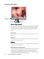
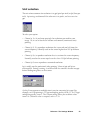
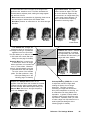
The Scan Material Status icon
Another way to access the Scan Material menu is to use the Scan Material Status
icon, located to the right of the Scan button.
Scan Material Status icon
The appearance of the Scan Material icon changes, depending on whether your
scan material is reflective, positive, or negative.
•
If you're scanning a reflective (such as a photo or print), this icon will
appear in its normal form like an ordinary icon. When you click on the icon
and hold down the mouse, you'll see the Reflective option checked.
Appearance of the Scan Material Status icon when scanning
reflective materials.
•
If you're scanning a positive transparency or filmstrip, this icon will appear
in the form of a positive. When you click on the icon and hold down the
mouse, you'll see the Positive Film option checked.
Appearance of the Scan Material Status icon when scanning a
positive transparency or filmstrip. Notice the perforations on the
top and bottom of the icon (characteristic of slides) to distinguish it
from the reflective icon.
•
If you're scanning a negative transparency or filmstrip, this icon will appear
in the form of a negative. When you click on the icon and hold down the
mouse, you'll see the Negative Film option checked.
Appearance of the Scan Material Status icon when
scanning a negative transparency or filmstrip.
Reference: The Preview Window
17
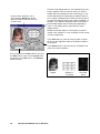
Color Matching Setup
To keep color consistency between the scanner, monitor, and printing device,
ScanWizard Pro applies Kodak CMS (Color management system) with ICC
(International Color Consortium) profile standards. For more information on
Color Management System, see Appendix.
Color Matching Set Up command lets you select the correct ICC profile for
matching with your color monitor and color printer.
When you install ScanWizard Pro, the CMS installer will prompt you to match
your color monitor and printer with the provided list. You may, however, change
and update your existing settings from this command. The default profile for
color monitor is “Generic P22 1.8 Gamma Monitor” and printer will set to
“Display”.
Display using monitor compensation
This option controls how the RGB destination data will be displayed. If this
option is unchecked, the RGB data is displayed directly to the monitor. If
checked, RGB destination data will be compensated to the selected monitor type
before it is displayed on the monitor.
Display
This feature allows you select color monitor type that is used for displaying RGB
data. The monitor profile will be applied only when “Display using monitor
compensation” option is checked.
Note: If the available
monitor types do not
include the one you
have, select Generic P22
or Generic EBU. These
two profiles are suitable
for most of the monitors.
18
Microtek ScanWizard Pro for Windows
Native mode RGB colorr matching (Native Color Mode only)
If unchecked, the ICC profile only applies to the RGB color for matching without
applying to other output devices (e.g., printer or image typesetter). If checked
the ICC profile applies to both the color monitor and output devices.
This check box should generally be checked unless you want to scan raw color
data, in which case you lose the compensatory effects of the Color Matching
system. Also note that it is not desirable to scan in raw data and then perform
data conversion, which will not generate the correct CMS effect.
Embed ICC destination profile in scan image
If checked, the ICC information is saved into the image file. This option is useful
especially for image application software, such as Photoshop.
RGB Destination
This feature lets you select the RGB output device (e.g., display monitor, or RGBbased printer) for matching RGB Color family images (including RGB colors, 48bit RGB colors, and 256 colors image types).
A number of RGB profiles is supplied by ScanWizard Pro. If you do not see the
ICC profile for your monitor or RGB device, contact your device manufacturer.
To add a specific ICC profile, click “Add Profiles” button to load it from the
floppy disk or CD-ROM that contains the ICC profile. Some device suppliers
(e.g., Kodak) have placed the ICC profiles in their web site. You may require to
download the ICC profile from their web sites.
Reference: The Preview Window
19
CMYK Destination
If your image type is CMYK color, this function lets you select the CMYK based
color printer or commercial offset printing standards for color separation.
Add Profiles
This command allows you add additional ICC profiles normally came with your
device (e.g., display monitor or printer).
Select the profiles you need, then click on the Open button to load the profiles
to ScanWizard Pro. This process takes a while for initialization.
Note: When you purchase color monitor or color printer, check to make sure your
supplier provides the corresponding ICC profiles.
20
Microtek ScanWizard Pro for Windows
Info
This command displays basic profile information for the current selected devices
Preview
Clicking on the Preview button immediately updates the Preview window image
when a new color profile is selected. This will reflect colors consistent with the
newly selected profile.
Refresh
Clicking on the Refresh button updates the ICC profiles that have been stored in
\Windows\System\ color and \Windows\System32\color folder.
Reference: The Preview Window
21
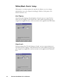
White/Black Points Setup
White point is a reference point that specifies the lightest area in an image,
making other areas to be adjusted accordingly. Likewise, black point is the
darkest reference area.
Auto Clipping
Auto white point clipping: For the lightness channel, you can assign black or
white level for clipping. To the White Point, colors under the percentage you
assigned are mapped to white; similar situation can be applied to the Black Point.
Output Levels
Minimum output level: For the lightness channel, you can assign minimum or
maximum level for clipping. To the Minimum level, colors under the percentage
you assigned are cropped out; similar situation can be applied to the Minimum
level.
22
Microtek ScanWizard Pro for Windows
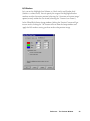
H/S Markers
Let’s you set the Highlight level (shown as a black circle) and Shadow level
(shown as a white circle). You can specify the range of the Highlight/shadow
markers to either the entire preview (selecting the “Overview or Preview image”
option) or only within the scan frame (selecting the “Current Scan Frame”).
In the White/Black Points Setup window, clicking the “Preview” button will get
instant result; clicking the “OK” button will exit from the Setup window and
apply the H/S markers setting you have made to the preview image.
Reference: The Preview Window
23
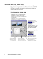
Cursor Auxiliary Lines
This command allows you to create horizontal and vertical grid lines with your
cursor to help define a scan frame precisely. Using the grid lines, you can also
read the measurements off your ruler more easily.
Cursor auxiliary lines on the
x and y axis
To use this feature:
1.
Choose the Cursor Auxiliary Lines command in the Preferences menu. From
the submenu that appears, select how the cursor lines will appear.
• On both x (horizontal) and y (vertical) axes
• On x axis only
• On y axis only
• None (no cursor lines)
Note: If your Preview window is close to the right edge of your monitor, the Cursor
Auxiliary Lines submenu may appear on the left side instead of on the right (as shown
above). To resolve this, move the Preview window towards the left to create enough room
for the submenu to drop down on the right.
24
Microtek ScanWizard Pro for Windows
2.
Click on the Frame tool.
To see how the cursor lines work, draw a scan frame. Click on the top left
corner of the image as your starting point, then drag down to form a scan
frame.
As you draw the scan frame, cursor lines will appear to help you draw the
scan frame precisely.
When you release the mouse, your scan frame will be aligned with the
cursor lines.
Click on the Frame tool, then
define a starting point.
Cursor lines appear to the
top and left of the image.
As you drag the mouse down,
the scan frame is aligned with
cursor lines on the x and y
axis (based on your selected
option in the submenu).
Reference: The Preview Window
25
Overview Setup
Specifies overview scanning speed options and the overview area for executing
the Overview command.
Overview Area
Choose Maximum Size, other fixed dimensions, or choose Custom Size then
enter the required dimensions. You may also set the Overview Area by dragging
the dotted boarders.
Unit
Lets you set the ruler units such as inch, cm, and mm.
26
Microtek ScanWizard Pro for Windows
Fast Overview
The Fast option supports faster scanning with the sacrifice of overview image
quality; on the contrary, if Fast Overview is unchecked, Overview scanning
speed is slow, but it obtains better overview image quality.
Overview automatically when ScanWizard Pro is started
If this option is checked, when ScanWizard Pro is launched, your scanner
automatically performs prescan, and shows the prescanned image in the preview
window. If unchecked, auto-preview is disabled, you should click the Overview
button to execute prescan.
Keep Overview image
If unchecked, the preview image will be cleared when you exit from ScanWizard
Pro and re-launch ScanWizard pro. If checked, the preview image stays on the
screen unless subsequent overview or prescan is performed.
Show confirmation message box if there is any prescan image
If this option is checked, a confirmation message appears, notifying you in the
preview window, a previously prescanned image exists. If unchecked, there is no
warning message in this occasion.
Preview
Click this button to get a scanning preview.
Reference: The Preview Window
27
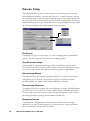
Prescan Setup
This command allows you to set the parameters of scanning a prescan image.
Major difference between Overview and Prescan is, Overview button scans the
area specified in the Overview Setup command getting a low resolution preview
image; where Prescan button only scans the selected scanning frame, resulting a
more detailed preview image. When the Prescan Setup dialog box (below) comes
up, click on the option you need or specify your parameters.
Fast Prescan
If checked, you get an coarse image at a faster scanning speed; if unchecked,
you get a quality image with the sacrifice of scanning speed.
Keep All prescan images
If unchecked, all of the preview images will be cleared when you exit from
ScanWizard Pro and re-launch ScanWizard pro. If checked, the preview images
stay on the screen unless subsequent overview or prescan is performed.
Prescan Image Margin
This option allows you to specify margin around the scan job in the first place,
subsequently you can adjust the scan frame slightly in the Prescan mode.
Available options are: None, Small, Medium (default), and Large.
Prescan Image Dimension
This option allows you to specify the size of the prescan image. Available options
are: Full screen, 75% screen, 50% screen, and Fit Preview Window. Size of the
Prescan image is not necessarily to fit into the specified option, it only is based
on the height/width ratio to get the maximum covered area.
Background Prescan
If checked, the background prescan function is enabled. You can assign a
number of scan jobs to execute prescan, in the mean time, carrying out other
jobs. If unchecked, this function is disabled.
28
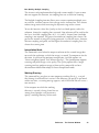
Microtek ScanWizard Pro for Windows
Monitor Gamma Setup
The Monitor Gamma Setup command lets you compensate linear intensity of the
monitor, making them consistent between preview image and the final scanned
image.
Monitor Gamma
Check this box to enable monitor gamma value setting.
When the monitor gamma option is checked, click the up/down arrow buttons,
making gray-level of the two boxes as close as possible. Click OK to confirm.
Reference: The Preview Window
29
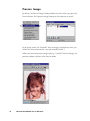
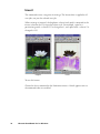
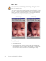
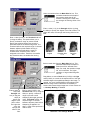
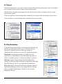
Invert
This command creates a negative of an image. The Invert effect is applied to all
scan jobs, not just the selected scan job.
When an image is inverted, the brightness value of each pixel is converted to the
inverse value on the 256-step color values scale. For example, a pixel in a
positive image with a value of 255 is changed to 0, and a pixel with a value of 5 is
changed to 250.
Original
Invert
To use this feature:
Choose the Invert command in the Preferences menu. A check appears next to
the command when it is enabled.
30
Microtek ScanWizard Pro for Windows
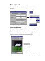
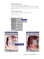
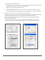
More command
The More command lets you specify less-frequently used, miscellaneous
parameters.
Smoked Glass Background
This command helps you distinguish the current scan frame from the rest of the
preview image for greater visibility of the current scan frame.
With the Smoked Glass feature turned on, the part of the image within the
current scan frame will stand out, while the rest of the image (the “irrelevant”
material) is relegated to a background resembling smoked glass.
Current scan frame
(with pulsing lines)
Part of image not in
any scan frame and
also hidden by smoked
glass background
Reference: The Preview Window
31
Confirmation Message
If checked, a confirmation message appears when you set image effect functions
such as Rotate or Flip. If unchecked, the message does not appear.
If checked, the image that is prescanned in the overview command remains on
the screen until another image acquisition is performed. If unchecked, the
overview image is deleted when you exit from ScanWizard Pro.
Color Space Mode
If LCH mode is selected, the color space is represented by Lightness, Chroma
(saturation), and Hue. If Native mode is selected, color enhancements are
performed in RGB, CMYK or Lab.
Scan Mode
During scan, you have these selections: Speed, Quality, and Best Quality.
The following selections are available as scan modes:
Speed
Higher scanning speed results in lower image quality.
Quality
With this option, the scan head remains stationary while the
CCD is being exposed to light source, resulting in better
images. Most scan materials can obtain a “quality” scan if this
mode is chosen.
Best Quality
This option is available for 10-, 12- or 16-bit scanners only.
The CCD exposure scheme is similar to that in the “Quality”
option, but image correction is first applied on the 10- or 12bit image, then converted to an 8-bit image. RGB Colors (48bit) image is always scanned in Best Quality option regardless
of any other option is selected. This option is useful for
scanning originals that have deteriorated in quality and for
performing image correction on them without losing detail.
Note: RGB color images are always scanned in the Best Quality mode, regardless of the
scan mode option selected.
32
Microtek ScanWizard Pro for Windows
Best Quality: Multiple Sampling
This feature is only implemented on high-end scanner models. If your scanner
does not support this function, no sampling lines are available for choosing.
The Multiple Sampling function allows your scanner to perform multiple scans
on each line, and then converts their average results into one line. This scheme
reduces image noise while increasing the dynamic range of the scanner.
To use this function, select Best Quality in the Scan Mode option, and in the
submenu, choose the sampling lines you need. Your selection will be used for the
final scan. Available sampling lines are 2, 4, 8, and 16; choose None if multiple
sampling is not required. The greater the number of sampling lines chosen, the
greater the amount of image data being processed. A trade-off occurs, however,
between sampling and speed, and the higher the number of sampling lines, the
slower the scanning time.
Interpolation Mode
This command is used when the output resolution of the scanned image does
not match the resolution at which the image is scanned. To compensate for the
deviation, ScanWizard Pro performs interpolation. Available options are
“Nearest neighbor (speed)” and “Bilinear (quality)”. The Speed option supports
scanning and yields images at fair quality. The Quality option takes a longer
scanning time but produces images of finer quality comparable to those
obtained from Adobe Photoshop's bi-linear interpolation mode.
Working Directory
This command lets you place to store temporary working files (e.g., scan job
files) during ScanWizard Pro's session. If the directory you specify is not found
or does not exist, a warning message appears, and ScanWizard Pro will create a
new one for it.
If the computer on which the working
directory is created is being shared for use
among several people, each person may
specify a working directory of their own.
Reference: The Preview Window
33
The Help Menu
The Help menu lets you access on-line help for ScanWizard Pro for Windows.
The Help menu uses standard Windows conventions for obtaining on-line help.
If you are not familiar with this procedure, refer to your Microsoft Windows
user's guide.
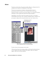
About
This command gives you information on the ScanWizard Pro for Windows
scanning software. ScanWizard Pro for Windows is also referred to in the About
screen as the ScanWizard Pro scanner controller.
34
Microtek ScanWizard Pro for Windows
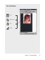
The Tool Buttons
Frame
Magnify Glass
Pane
Dropper
Reference: The Preview Window
35
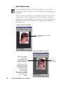
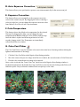
Scan Frame tool
The Frame tool lets you create a scan frame or multiple scan frames in the
preview image, which is the active area on which controls and commands can
be applied.
The Frame tool can also be used to create multiple scan frames, but only one
can be current at a time; the current scan frame is indicated by a marquee
(marching ants, or dotted boarders). The current scan frame can be more easily
distinguished if you turn on the Smoked Glass Background command (in the
Preferences menu).
Image with single scan frame
Current scan frame is denoted
by marquee
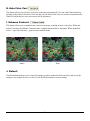
Image with multiple scan frames
Another scan frames,
which can be
distinguished by the
marquee around the
right half of the image.
This is not the current
scan frame, however, as
the part of the image
enclosed by the scan
frame is dimmed.
Smoked Glass
Background is on so that
the current scan frames
can be seen more
clearly.
36
Microtek ScanWizard Pro for Windows
Current
scan frame
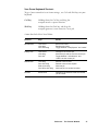
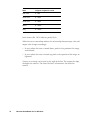
Scan Frame Keyboard Shortcuts
To get a better controls of scan frame settings, use Ctrl and Shift keys on your
keyboard.
Ctrl key
Holding down the Ctrl key and drag the
marquee results a square selection.
Shift key
Holding down the Shift key and drag the
marquee generates a new frame for a scan job.
A more detailed table is listed below.
Function
Keys
Result
Move/Resize
click+move
click+drag
Ctrl+click+drag
Move scan frame.
Resize scan frame.
Toggle between “Keep Square” and “resize”.
Change Job
click+move
click+drag
Ctrl+click
Change to the current job.
Select the job and set it to the current job.
Toggle between “Job selection” and
“make it as the current job”.
Redraw/Add
click+drag
Ctrl+click+drag
Shift+click+drag
Ctrl+Shift+click+drag
Redraw current frame.
Redraw current frame square.
Add new job.
Add new job in a square boundary.
Prescan
double-click
Change to the Prescan mode and set the
job as current.
Reference: The Preview Window
37
To use the Frame tool:
1.
Click on the Frame tool.
2.
Move the pointer (now a crossbar) to the preview image, and draw a frame
enclosing the area to be selected. When you release the mouse, the scan
frame will be in a marquee.
To make multiple scan frames (which would add scan jobs), hold down the
Shift key and drag the mouse. For more information on scan jobs, refer to
the Scan Job section of the Reference.
3.
38
To resize the scan frame, do either of the following:
•
Move the cursor to any corner of the frame; the pointer will change to
a double-headed arrow. Hold down the mouse, and drag to form a new
area, then release the mouse; or
•
Click on the Frame tool again and restart the area-selection process.
Microtek ScanWizard Pro for Windows
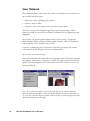
Magnify Glass tool
The Magnify Glass tool enlarges your view of the preview image, allowing you to
set the scan frame with greater precision if you need to. Only your view of the
preview image is changed; the actual size of the image remains unaffected.
Each click of the Magnify Glass tool magnifies or reduces by a factor of 2. Thus,
the magnification levels increase from 100% to 200%, to 400%, and to the
maximum 800%.
Original image view
Image view enlarged with
Magnify Glass tool
To enlarge the view:
1.
Click on the Magnify Glass tool.
2.
Place the pointer — now a lens with a plus sign inside it — on the image
and click.
To reduce the view, hold down the Shift key and click again. The plus sign
changes to a minus sign when you hold down the Shift key.
Reference: The Preview Window
39
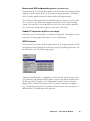
Pane tool
The Pane tool lets you scroll through a preview image, allowing you to move
parts of the image into view.
The Pane tool can be used for zoomed-in images (enlarged through the Magnify
Glass tool), or images not included completely within the frame of the preview
window (for instance, if your preview image is 7 inches wide and you resized
the width of your overview/preview window to only 3 inches).
Zoomed-in image
Scrolled image
To use the Pane tool:
1. Click on the Pane tool.
2. Move the pointer (now a hand) to the image. Hold down the mouse and
move the hand left, right, up, or down, and see portions of the image come
into view. You can also use the scroll bars to scroll through the image.
40
Microtek ScanWizard Pro for Windows
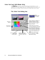
Dropper tool
The Dropper tool creates tag windows for setting White and Black points. If in
LCH mode, Add/Remove Cast is present. When you click on the preview image,
the tag window instantly displays the pixel information.
The Dropper tool allows you to sample color from an area of an image, and to
designate a new white or black point. The two buttons let you select black and
white points for the current job. Using the same pair of tag windows, you can
apply black and white points to several jobs.
With the Dropper tool, you can determine the color values for any pixel in an
image. When you click on the Dropper tool and pass over a pixel, the value of
that pixel will be displayed in the Information window, based on the sample size
also selected in the Information window. Pixel-value information is useful
especially when you're making color adjustments based on color values.
To create a Tag window
The Tag window displays coordination (x, y) position and the pixel values
(RGB, CMYK, Lab, et. al.), depending on the image mode you select for the
current scan job. The tag contents are updated according to the current job
settings.
Reference: The Preview Window
41
To close the Tag window
Clicking on the Close box closes the Tag window. To close all Tag windows,
holding down the Shift key, then click on any Close box.
Choosing Black and White Droppers
Holding down the Ctrl key enables the Black dropper. Holding down the Alt key
enables the White dropper.
Input display Mode switch
To change the input display (Native color or LCH color), click on the Mode
Changing triangle.
Black, White, and Color diamonds
The black (for the shadow) and white (for the highlight) diamonds are used to
apply the shadow and highlight points indicated on the Tag windows to the
image.
42
•
To set the shadow point on the image to its Tag Windows value, click the
black diamond.
•
To set the highlight point on the image to its Tag Windows value, click the
white diamond.
•
The Color diamond: The color diamond is used to add or remove color cast
to the selected color. Remove color cast is the default, indicated by a minus
sign. To add color cast, click the title bar of the Tag Window, then hold
down the Alt key, the minus sign is changed to plus sign, than add the
color cast.
•
Color display: The color strip shows the color selected by the Tag Windows
Tools
Microtek ScanWizard Pro for Windows
Setting White/Black points
There are two ways to set White and Black points:
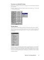
1) Choose it from the Tag window, and 2) choose it directly from the Dropper
(holding down the Ctrl key to select Black point, and the Alt key to select White
point).
To restore original settings:
Select “No Correction” from the White/Black points menu.
- or Click on the “Reset” button.
Before restore
After restore
Reference: The Preview Window
43
To change the sample size of the Dropper:
1.
Open the Information window by choosing the Show Info Window
command in the View menu.
2.
Click on the Sample Size button, located to the right of the RGB values in
the Information window.
3.
Choose your options.
Select the sample size. For instance, the 1 by 1 option will display the value
of one pixel — the one in the middle of the Color Meter Display. The 3 X 3
option reads the average value of a 3-pixel by 3-pixel area.
To display color information for a pixel or an averaged area:
1.
Click on the Dropper tool.
2.
As you pass over a point in the image, see the Information Window — the
RGB, CMYK, or Lab values will be displayed in the Color Meter Display.
These values are in turn based on the sample size you selected.
Dropper Keyboard Shortcuts
To get a better controls of scan frame settings, use Ctrl and Shift keys on your
keyboard.
44
Key
Function
Click
Clicking on the preview image generates a Tag window.
Ctrl key
Holding down the Ctrl key, the Dropper tool becomes a Black Point tool.
Alt key
Holding down the Alt key, the Dropper tool becomes a White Point tool.
Microtek ScanWizard Pro for Windows
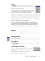
Action Buttons
The Overview button scans a low resolution preview at a size
specified in the Overview Setup command.
The Prescan button performs high resolution preview for the
selected scan jobs.
The Scan button lets you scan the image in your scanner and
delivers it to your image-editing software. The scanned image
is based on the specifications you have chosen in the Settings
window and on controls you may have applied to the preview
image if a preview was performed.
If you bring up ScanWizard Pro directly without using other
application program, the Scan button turns out to be Batch
button, and you are in the Batch scanning mode. In this mode,
you can scan multiple jobs in a single pass.
Reference: The Preview Window
45
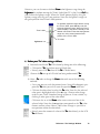
Rulers
The rulers on both sides of the preview window help you with operations that
need precise measurement and alignment of your image.
The unit of measurement in the rulers is determined by the unit of
measurement you have selected. This can be done either in the Image
Dimension controls, located in the Settings window, or by clicking on the ruler
unit button at the 0,0 point of the rulers in the Preview window.
Depending on your chosen unit of measurement, the rulers can mark off
measurement in these units: inch, centimeter, millimeter, point, and pixel. The
pixel option is dimmed if the selected resolution unit is lpi, and vice versa.
Pressing the ruler unit
button displays the
measurement menu.
Select the unit of measurement for the rulers in
either the Settings window or the Preview window.
To select the unit of measurement for the rulers:
Click on the unit box in the Settings window, or click on the ruler unit button
at the 0,0 point of the rulers in the Preview window. When the submenu
appears, select the unit of measurement.
46
Microtek ScanWizard Pro for Windows
Preview Area
The preview area is where the preview image appears.
The dimension of the preview area varies, depending on your scanner model.
The size can be changed, however, through the Overview Setup command in the
Preferences menu. You can increase the size of the preview area to see more
detail in your image, or you can reduce the preview area to save on memory.
For details on how to change the size of the preview area, refer to the Overview
Setup command in the Preferences menu section.
Preview area
Reference: The Preview Window
47
Auxiliary information
Preview image
resolution
Zoom scale
Zoom-out
Flash Markers
Zoom-in
Preview image resolution
resolution:
When Overview or Prescan command is executed, the preview window displays
the prescan image, also the auxiliary information shows the preview image
resolution. Preview image resolution is changed according to the size of the
preview window. To resize preview window, drag any side or corner of the
window.
Zoom scale
Lets you choose the size of the preview image, ranging from 100%, 200%, 400%
to 800%.
Zoom-out
Each time you click on this zoom-out icon, the preview image is reduced one
zoom scale level, minimum 100%.
Zoom-in
Each time you click on this zoom-in icon, the preview image is enlarged one
zoom scale level, maximum 800%.
White/Dark points marker flasher
When preview image is displayed, the white point marker (the extremely white
reference point) and the dark point marker (the extremely black reference
point) are shown. Sometimes the two markers cannot be visually detected,
clicking on the White/Dark points marker flasher activates the markers to flash
5 times. When they flash, the locations can be seen.
48
Microtek ScanWizard Pro for Windows
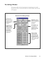
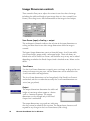
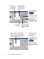
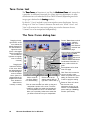
The Settings Window
The Settings window contains the parameters for outputting your scanned
image for the current scan job and includes the advanced image correction tools
of the program.
Elements of the Settings window
Resolution edit
box: Lets you enter
a resolution value in
which your image will
be output (not
scanned).
Image Dimension
controls: include
various parameters
for specifying scan
frame width and
height, scaling,
output width and
height, and unit of
measurement.
Type menu: Lets you
select the image type in
which your image will be
scanned and
processed.
Unit selection: Lets
you choose the unit of
measurement for
resolution in either ppi
(pixel per inch) or lpi
(lines per inch).
Advanced Image
Correction tools:
Improve image quality
by enhancing image
characteristics such as
brightness and contrast,
white and black points,
and others.
Reference: The Settings Window
49
Output Image Parameters
The Output Image Parameters include the various controls that determine how
your image is scanned and processed.
The Output Image Parameters include:
• Type
• Resolution
• Unit Selection
• Image Dimension controls
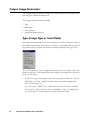
Type (Image Type or Scan Mode)
The Type menu determines what your resulting scan will be. It does not refer to
the original image mode. For instance, if you have a color photo but choose 256
grayscale for the scan mode, the photo is scanned and processed as grayscale.
To use the Type menu, from the Type menu, select your scan mode. Choose the
correct image type, as the wrong choice will simply create bigger files that won't
be of any use to you.
• If you have a grayscale original, do not set image type to RGB Colors (48-bit).
RGB colors are 24-bit, and RGB (48-bit) colors are used for applications
such as Photoshop 5.0.
Note: The options of RGB Colors (48-bit) and Gray Scale (16-bit) are available
only for 36-bit or above scanners, such as ScanMaker 5. Only a few applications
(e.g., Photoshop 5.0) in the market today support these two options.
50
Microtek ScanWizard Pro for Windows
• CMYK color separation is used for commercial printing. Some image editing
software program, such as Photoshop 5.0 full version, have the capability of
processing CMYK file format. ScanWizard Pro CMYK color supports US
SWOP, European, and Japanese printing ink standards. For more information, refer to Appendix C.
• Web/Internet color is 256-indexed color image converted with uniform
palette and error diffusion. The sRGB (web color standards) profile is used
for color matching with this image type.
• Customized 256 color option lets you select the attributes of indexed color.
If this option is selected, the following dialog box displayed.
Palette
Lets you choose the method of creating
color palette table. “Uniform” uses 6-6-6
levels fixed color palette table,
independent of the contents of the 24-bit
RGB image. By default, the “Adaptive” is
selected, this option creates color palette
table from commonly used areas of the
color spectrum that appears in the image.
Since colors in most images are
concentrated in particular areas of the
spectrum, this option is generally used.
Dither
Lets you choose the dithering method. Dithering can further improves the
256-index color image quality by mixing the available colors to simulate the
missing colors. “None” disables dithering; “Pattern” uses a structured pattern
to simulate the missing colors, this option is grayed out for Adaptive palette;
and “Diffusion”, which is the default, produces the best quality of 256indexed color image with lowering a little bit the scanning speed due to
intensive algorithm computation is required.
• Default attribute of 256-color is the last customized 256-color setting.
• B&W Diffusion image type is 1-bit B&W image dithered with error
diffusion effect.
• Save As 256 color
You may save the palette and Dither selections as the defaulted 256
colors, to be selected from the Type menu.
Reference: The Settings Window
51
Resolution
Resolution in the Settings window refers to the desired resolution for outputting
the image to a device, such as a monitor or printer. It does not refer to the
resolution in which the image is scanned.
To set your resolution:
Enter a resolution setting in the Resolution edit box, then press Enter. If the
value you enter is too low or too high, the minimum or maximum resolution
value is entered for you instead.
According to the image type you select, default resolution is displayed. When
you specify the resolution you need, this value is recorded for subsequent use.
ScanWizard Pro records last 6 different resolution settings.
Note: In setting resolution, choose the setting that best matches your output device.
Remember that the higher the resolution, the larger the resulting file will be and the
longer it will take to output.
52
Microtek ScanWizard Pro for Windows
Unit selection
The unit of measurement for resolution is in ppi (pixel per inch) or lpi (lines per
inch). Lpi settings are dimmed if the ruler unit is in pixels, and vice versa for
ppi.
To select your option:
• Choose lpi (1x) if you know precisely the resolution you need for your
image. Or, in case of Stochastic halftone and contone (continuous tone)
printing.
• Choose lpi (1.5x) to produce resolution that is one and one-half times the
screen frequency. Normally used on the screen higher than 133 lpi halftone
printing.
• Choose lpi (2x) to produce resolution that is two times the screen frequency.
Normally used on the screen equal to or less than 133 lpi halftone printing.
• Choose lpi Custom to produce customized resolution.
Lpi is widely used in professional offset printing. Values of ppi and lpi are
exchangeable. During scanning, ScanWizard Pro first converts the unit into ppi
before sending image data to the scanner.
Quality Factor represents multiplication factor for converting lpi to ppi. For
example, an 85 lpi printing is 127 ppi multiplying quality factor 1.5; or 170 ppi
multiplying quality factor 2. The Custom setting allows you to define values
from 1 to 4, decimal value is accepted, such as 1.33.
Reference: The Settings Window
53
Image Dimension controls
These controls allow you to adjust the various factors that affect the image,
including the width and height of your image when it is first scanned (Scan
Frame), the scaling factor, and the dimensions of the image in final output.
Scan Frame (input) x Scaling = output
This mathematical formula indicates the relation of the input dimensions to
scaling and how these factors affect image dimensions when the image is
scanned.
The Input-Output dimensions consist of four edit boxes: Scan Frame width,
Scan Frame height, output width, and output height. These edit boxes are
linked to the use of Fixed Scan Frame, and the boxes may or may not be edited
depending on whether the Fixed Output Sized is checked or not. Below are the
details.
Scan Frame
Use the Scan Frame dimensions to specify your scan frame; or drag on the scan
frame to whatever size you want, and the dimensions will be reflected in the
Scan Frame width and height boxes.
The Scan Frame dimensions can be changed only if the Fixed Scan Frame is
unchecked, and this is evident because only the Scan Frame dimensions are
active (not grayed out).
Output
The output dimensions determine the width and
height of your image when output to a device
such as a monitor or printer. The output
dimensions can be changed only if the Fixed
Output Size is unchecked.
The output dimensions are grayed out, indicating
that they cannot be edited in this situation. The output boxes, however, will
respond to any changes in the Scan Frame boxes (and scaling).
54
Microtek ScanWizard Pro for Windows
Scaling
The Scaling lets you create large or small images so that the
images don't have to be resized subsequently, which is usually
done in your image-editing software.
Scaling is the process of creating larger or smaller images in your
scanning software so that you need not resize the images later
when they are delivered to your image-editing program.
Specific scales: Choose from 1/2x (half size), 1x (full scale), 2x (enlarged to
twice size), 4x, and 8x. Film scale mapping: Choose your image material and the
output dimension. For example, “35mm to 5” x 7"” means your image source is
35mm film, and output size is 5" x 7". Add to Menu: You can customize the
image mapping scale, and name it for later use. Restore: Retrieve the image scale
name you assigned in the Add to Menu command.
The above assumes that your resolution is held constant throughout the
changes. When you change resolution and specify a value that has no exact
equivalent for scaling, the scaling may be affected and adjusts itself to the
nearest allowed value. For instance, if your resolution is 100, your scaling
becomes 99 (instead of a full 100), because that is the closest scaling equivalent,
given the resolution value.
Image Size
The Size indicates how big the file will be when you accept the dimensions
shown in the edit boxes, together with the resolution setting that you selected.
Size is calculated automatically.
Unit of Measurement
ement allows you to select your unit of measure. The
The Unit of Measur
Measurement
options include inch, centimeter (cm), millimeter (mm), point, pixel, and pica.
Keep Proportion
opor
tion option allows you to keep the ratio of the image width
The Keep Pr
Propor
oportion
and height constant.
Transform (Rotate and Flip tool)
Click the “F” icon to bring up rotate and horizontal image
flip selections. The “F” icon represents the current selected
orientation job.
Image effect of the Flip tool applies to prescan and
scanned image, not the overview image.
Reference: The Settings Window
55
To use the Image Dimension controls
1.
Select the unit of measurement
2.
Enter a value in the applicable edit boxes (width input, height input,
scaling, width output, height output)
3.
Scan Frame width and Scan Frame height refer to the dimensions of the
scan frame that you draw. For example, if the image on your scanner is 5" x
7" and you draw a scan frame that is 3" x 4", then your Scan Frame width
will show 3.00 and your Scan Frame height will show 4.00.
The Scan Frame width, Scan Frame height, output width, and output height are
affected by your scaling and whether you have checked the Keep Proportion
option or not.
To specify a name for frame: You may give a specific resolution a name for easier
access. To begin, set the Width/Height of the scan frame, click the small triangle
underneath the Resolution setting. A dialog box appears for your entering the
frame name. Input a name you want, then choose Add to menu.
You may also specify names for the Scaling and Output values.
56
Microtek ScanWizard Pro for Windows
Advanced Image Correction Tools
LCH Color Space Mode AIC Tools
Native Color Space Mode AIC Tools
Available Image Correction Effects
ScanWizard Pro automatically locates all settings (default and the existing
custom settings) from a specific directory, and made them available in the
Advance Image Correction (AIC) dialog box.
Not all image correction tools are available for all types of scan material and
output images. Non-applicable AIC tools are dimmed when the selected image
type is not supported by such tools.
RGB
CMYK
Lab
Gray
Line-art
B&W
Diffusion
Remark
Dynamic Range
9
9
9
9
White/Black Points
9
9
9
9
Gradation
9
9
9
9
Color Cast
9
9
9
LCH mode only
Saturation
9
9
9
LCH mode only
Selective
9
9
9
LCH mode only
Tone Curve
9
9
9
9
Filter
9
9
9
9
Descreen
9
9
9
9
Brightness & Contrast
9
Color Correction
9
9
*
LCH mode only
9
9
**
Native mode only
Native mode only
* For “Line-art” output, White/Black Points will switch to Threshold AIC tool.
When output type is “B&W diffusion”, this AIC tool is dimmed.
**For negative films scan material, the Descreen AIC tool changes to Film Type selection.
Reference: The Settings Window
57
Introducing the Image Correction tools
With the image correction tools, you can edit the characteristics of your image
during scan stage. The image correction tools in ScanWizard Pro save you time
and provide you with the needed flexibility to adjust images right within the
scanning software.
Although you can use all the image correction tools, you don't need to use
everyone of them to achieve a great image. Perhaps all that's needed is a change
in the shadows or gamma curve. Try experimenting with the tools to see which
one provides the optimal results.
Using the Advanced Image Correction dialog
box
When you click on any of the image correction tools, or select Custom... in the
Settings window, the Advanced Image Correction (AIC) dialog box appears. In
this box, you can do the following:
1.. These are the thumbnails of the image captured by your scanner. The left
thumbnail is the “before” version — which shows the effects of the last
saved settings values. The right thumbnail is the “after” version — which
shows the effects of the new settings added in the AIC.
58
2.
To select another image correction tool, click on any of the buttons
displayed in the vertical toolbar on the right side of the dialog box.
3.
Click on an action button to achieve a particular effect.
Microtek ScanWizard Pro for Windows
The Action Buttons in the AIC dialog box
The Action buttons in the AIC dialog box carry out a specific action.
1:1 Thumbnails
If checked, size of the thumbnail is about the same as the image shown in the
Preview window. If unchecked, the image size appears fit into the shown dialog
box.
Hide Thumbnails
If checked, the “before” and “after” thumbnails becomes hidden. To redisplay,
click the “Up” arrow at the left side of the dialog box.
Preview
If checked, the AIC image correction effect applies to the Preview image in real
time.
Reference: The Settings Window
59
The OK button
Clicking on this button will apply whatever Image Corrections you have
performed on the current scan job, and close the AIC dialog box.
Example
Example: If you increased brightness, changed the saturation, and then clicked
OK, all the changes are applied, and you exit the AIC dialog box. The settings
are changed as Customized status.
The Cancel button
Clicking on this button will cancel out all image correction changes you have
made to the current scan job, and then close the AIC dialog box. The settings
remained unchanged.
Example: If you applied filters, changed the curve, and then clicked Cancel,
none of the changes will take effect, and you exit the AIC dialog box.
The Default button
If Reset is selected, the settings are restored to their default values; if Cancel is
selected, the operation has no effect.
The Revert button
Clicking on this button cancels out the changes you made with the current
image correction tool. This means that if you used several tools (and achieved a
look that is the cumulative effect of all the tools), using Revert will cancel the
effect of only the current tool and preserve the effects of the other preceding
tools.
The Add to Menu button
Clicking on this button to save the settings you have made as a name. You may
retrieve this user-defined AIC setting afterwards from the Setting windows.
Maximum 20 sets of user-defined settings for each AIC function.
Example: Suppose you have set a Dynamic Range for future use, at the
Description column, you input “24-bit color” string.
60
Microtek ScanWizard Pro for Windows
To retrieve user-defined AIC settings
From Settings window, select the AIC settings you have made from the respective
AIC command.
Example: Suppose the Dynamic Range settings of your input (e.g., 24-bit color)
is available for choosing.
The Reset button
Clicking on this button brings up the Reset dialog box, where you can specify
which settings are to be reset, then click Reset or Cancel. If Reset is selected, the
settings are restored to their default values; if Cancel is selected, the operation
has no effect.
Example: If you changed white/black points, changed brightness, then clicked
on Reset and chose to reset brightness, the brightness setting of the scan job is
restored to its default; but the altered shadows and highlights remains in effect.
If you reset both white/black points and brightness, then those values are both
restored to default.
Reference: The Settings Window
61
To remove user-defined AIC settings
From Settings window, choose the AIC function, then select the Remove
Settings item.
A Settings dialog box appears.
Select the Settings you want to remove, click the Remove button.
62
Microtek ScanWizard Pro for Windows
Dynamic Range tool
This tool lets you locate the lightest tone (Dmin) and the darkest tone (Dmax)
of the original in the prescan image; and then capture the full tonal range of the
final scan image without posterization.
The maximum dynamic range depends on the bit depth of the scanner model.
For example, a 12-bit per (R, G, and B) color scanner may have 3.6D in
dynamic range; where a 8-bit per color scanner will have lower dynamic range.
Dynamic range differs from scan materials as well. A piece of positive original
can have a dynamic range up to 4.0D, yet negative original or reflective material
(picture or printed document) results a dynamic range possibly equal or lower
than 2.0D. Without optimized remapping from scanner's dynamic range to the
dynamic range of the original, tonal range of the image will not be fully
captured, resulting poor contrast.
Automatic dynamic range setting determines the lightest tone (Dmin) and
darkest tone (Dmax) of the original automatically, then captures the image with
the full input tonal range of the scanner. This setting optimizes the contrast of
the output image, most useful for scanning negative films.
Note: Automatic dynamic range is not suitable for originals such as image contains
direct light sources or specular highlights such as reflections from shining metal or
bright glass surfaces, these should be kept as purely white. An automatic Dmin may
generally be placed incorrectly in specular highlights, causing other highlights and
midtones to be darkened. In addition, automatic Dmin/Dmax setting is not suitable
for low-key and high-key images.
Reference: The Settings Window
63
The Dynamic Range dialog box
By default, this tool automatically determines the lightest density or tone (Dmin)
and darkest tone (Dmax) of the original; then it captures the image color data
(histogram area) with the full input tonal range of the scanner. This setting
optimizes color balance and the contrast of the output image, and is most useful
for scanning negative films. You can override the auto-settings by defining your
own custom dynamic range (Dmin/Dmax) values to all or each individual RGB
channels. Manual setting tools are provided in the AIC Dynamic Range dialog
box shown below.
"Automatic" is
checked & will
display to indicate
auto setting is on
when the Auto
button is clicked
Access to
other AIC tools
Drag sliders to
define custom
Dmin/Dmax
settings
Click to automatically or
manually balance
all RGB channels
Enter custom
Dmax setting
here
Click to automatically or
manually balance
individual RGB
channel
Enter custom
Dmin setting
here
Click to automatically apply the
full range setting
"Custom" is
checked & will
display to indicate
manual setting is
on when the Dmin
or Dmax is
manually adjusted
Click to delete
saved custom
Dynamic Range
settings (if any)
from folder
Click to revert to the
Scan Wizard Pro
default setting
Click to apply or revert to
automatic setting (ScanWizard Pro algorithm) when
dissatisfied with manual
setting
64
Click to revert to
the custom setting
defined right after
current start up
Microtek ScanWizard Pro for Windows
Click to save and add
the current custom
setting to Dynamic
Range pre-set
settings
Observe histogram
density values at cursor
position as it is swept
around the histogram
You can also use the Eyedropper tools to define Dmin and Dmax settings. Just
move the cursor toward the prescan image while the AIC Dynamic Range dialog
box is on display. Notice that the cursor automatically transform itself into Black
Eyedropper tool (default).
The Black Eyedropper tool appears when
you move cursor toward the prescan
while AIC Dynamic Range dialog box is
on display.
Enable this check box to
show simulated effect of
the adjustment on the
prescan image
Use this tool to manually define your Dmin
(shadow) setting.
Press Alt key to switch tool into White
Eyedropper and use it to assign the Dmax
(highlight) setting.
Release Alt key to revert back to Black
Eyedropper tool.
Reference: The Settings Window
65
White/Black Points tool
For color and gray images, this tool allows you set white/black points; for lineart image, it carries out threshold adjustment feature.
The White/Black Points dialog box (Color/Gray image)
By default, this tool automatically determines the lightness (but not chroma and
hue) of a prescan color or gray image. When the default setting fails to provide
the lightness you want for your prescan, you can click the Auto button to allow
the tool to analyze your prescan and then auto-clip the White and Black points
of the Lightness histogram to optimize lightness of the output image. You can
override the auto setting by providing your own custom clipping values in the
L " edit box for both White and Black points or .
"L
The tool also provide option to auto-neutralize undesirable color cast in either
or both highlight and shadow areas of the image.
Observe Histogram Input Lightness,
Pixel Counts, & % of Lightness
values at cursor position as it is
swept around the histogram
Check to AutoNeutralize unwanted
color cast in Highlight
(White) area (LCH
Mode only)
Access to
other AIC tools
Drag sliders to define
custom Lightness settings
Click to define custom
parameters (in %) for
Auto Clipping, Output
Levels, and Highlight/
Shadow Markers
Enter custom Lightness,
Chroma, & Hue values for
Shadow (Black) area here.
C & H values are
applicable only when the
Shadow check box of
Auto Neutralize is enabled
Enter custom Lightness,
Chroma, & Hue values for
Highlight (White) area here.
C & H values are
applicable only when the
Highlight check box of
Auto Neutralize is enabled
66
Check to AutoNeutralize unwanted
color cast in Shadow
(Black) area (LCH
Mode only)
Click to apply the
automatic (ScanWizard Pro algorithm)
or custom clipping
setup values of the
prescan
Click to revert to
the Scan Wizard
Pro default setting
Microtek ScanWizard Pro for Windows
Click to revert to the
custom setting defined
right after current start up
Click to save and add
the current custom
setting to Lightness
preset settings
You can also use the Eyedropper tools to define the two end points of the
Highlight (White) and Shadow (Black). Simply move the cursor toward the
prescan image while the AIC White/Black Points dialog box is on display. Notice
that the cursor automatically transform itself into Black Eyedropper tool
(default).
The Black Eyedropper tool appears when
you move cursor toward the prescan
while AIC White/Black Points dialog box is
on display.
Enable this check box to
show simulated effect of
the adjustment on the
prescan image
Use this tool to manually define your
Black (Shadow) Point setting.
Press Alt key to switch tool into White
Eyedropper and use it to assign the White
(Highlight) Point setting.
Release Alt key to revert back to Black
Eyedropper tool.
Reference: The Settings Window
67
The Threshold dialog box (Line-art image)
For line-art image, the White/Black Point tool becomes a Threshold correction
tool.
The threshold values are in the range of 0 through 255.
Sharpen
This option lets you further enhance line-art image quality if your original lineart material appears blur (e.g., text printed by inkjet, dot matrix printer, or
contains text of small points).
68
Microtek ScanWizard Pro for Windows
Gradation Curve tool (LCH mode only)
The Gradation Curve tool lets you control the gamma, which measures the
intensity affecting the mid-level grays (midtones) of an image.
Gamma is commonly used to describe the relationship between output density
to the original density across the mid-tones. Adjusting the gamma lets you
change the values of the middle range of gray tones without dramatically
altering the shadows and highlights.
In many ways, the Gradation Curve tool gives you the most control for adjusting
an image's values, but beginners may take some time to master its intricacies.
The Gradation Curve tool applies to grayscale and color images and is not
available for use with line-art or halftone scan modes.
How to read the curve
Original curve: Straight
diagonal line
Modified curve with
points moved up
The curve shows the relationship of the brightness changes across the middle
pixels between the resulting image and the original.
When you open the Curves dialog box, the line on the graph is diagonal
because the Input and Output values are the same.
The x axis of the graph represents the original brightness values of the pixels,
from 0 to 255, for 8-bit scanners (see the table on next page); the y axis
represents the new brightness values. Clicking on the diagonal line then plots a
point that can be adjusted.
Reference: The Settings Window
69
Scan
Original brightness value
8-bit color
0 - 255
10-bit color
0 - 1023
12-bit color
0 - 4095
CMYK
0 - 100%
Gray
0 - 100%
In the above table, 100% indicates purely black.
When the curve is moved up or down, the relationship between input value and
output value changes accordingly.
• In areas where the curve is moved down, pixels in that portion of the image
are darkened.
• In areas where the curve is moved up, pixels in that portion of the image are
lightened.
Contrast in an image can be seen by the angle of the line. The steeper the slope,
the higher the contrast. The closer the line is to horizontal, the lower the
contrast.
70
Microtek ScanWizard Pro for Windows
The Gradation Curve dialog box
The Gradation tool enables you adjust the toner distribution of an image to
create a gradual transition between two or more colors. This is where LCH color
system has its great advantage. With this tool you can easily change the
brightness and contrast without affecting the gray balance and saturation of an
image. This is because chroma and hue values are always kept constant.
To prevent the color images from becoming too light or too dark, ScanWizard
Pro provides a Saturation Range option. With this option, colors outside of a
given chroma range will not be affected by the gradation curve manipulation.
NO
TE To separately adjust toner of individual RGB channel, a
NOTE
ve tool is provided for such purpose. See section on
separate Tone Cur
Curve
"Optimizing Image with Tone Curve Tool" in this chapter.
Current Gradation method
used is "Curve" (default).
See "Line"
and "Gamma"
methods next
page
Dragging the topright section of
the curve below
the default
diagonal line will
add shadow to
light tones
Click Auto to apply the auto
(based on ScanWizard Pro
algorithm) Gradation setting
of the prescan
Dragging the
bottom-left section
of the curve above
the default diagonal
line will add
lightenness to
shadow tones
Click to create handles
from which to drag and
manipulate a portion of
the curve. The more
handles is created, the
easier and smoother it
is to manipulate the
curve. The handles
also allow you to
precisely isolate tone
areas that you want to
exclude from your
manipulation.
Click to revert to
the Scan Wizard
Pro default setting
Click to revert to the
custom setting defined
right after current start
up
Coordinates information of
cursor position within the
grids
Check to enable Saturation
Range option check box. Then
drag sliders or enter values in
the setting edit boxes to define
saturation (chroma) range
(colors outside the chroma
range will not be affected by
the Gradation curve)
Click to save current custom
(curve) parameters to
Gradation preset settings
Reference: The Settings Window
71
Dragging the lower
left section of the
line above the
default diagonal line
will add shadow to
light tones
Dragging the upper
right section of the
line below the default
diagonal line will add
lightness to shadow
tones
Current Gradation method
used is
"Line"
Coordinates information of
cursor position within grid
This section (higher chroma
and outside the set
Saturation Range; 51 to
100) will NOT be affected
by Gradation adjustment
These sections
of color tones are
unchanged
Only this section (lower
chroma) of Saturation
Range; 0 to 50, will be
affected by Gradation
adjustment
Dragging the Gamma handle toward left
(Gamma value above 1.00), will lighten the
dark tones. Likewise, dragging the handle
toward right (Gamma value below 1.00), will
add shadow to light tones & vise versa
Enable this check box to
show simulated effect of
the adjustment on the
prescan image
Current Gradation method
used is
"Gamma"
Instead of dragging the
Gamma handle, you may
directly enter the appropriate
Gamma value in this setting
edit box
72
Microtek ScanWizard Pro for Windows
You can also use the Eyedropper tools to define the Saturation Range. Simply
move the cursor toward the prescan image while the Saturation Range check
box is enabled. Notice that the cursor automatically transform itself into White
Eyedropper tool (default).
The White Eyedropper tool appears when
you move cursor toward the prescan
while the Saturation Range check box
is enabled
Check this check box to
enable Saturation Range
option. You can use either
the saturation sliders or
Eyedropper tool to set
saturation range to be
subjected for Gradation
Use this tool to manually define your high
chroma range setting
Press Alt key to switch tool into Black
Eyedropper and use it to assign the low
chroma setting
Release Alt key to revert back to White
Eyedropper tool
Reference: The Settings Window
73
Color Cast tool (LCH Mode Only)
The Color Cast tool is most useful in eliminating unwanted color cast and
adding color cast where proper color cast is lacking to maintain the neutral and
gray balance of an image. You must initially select mode before color casting.
The Color Cast dialog box
Select Color Cast mode
"Remove Cast"
is the default
Define Lightness by adjusting "L"
Handle and observe corresponding "L" value in the edit box.
You can also enter "L" value
directly in the box
Lightness
Handle
Chroma and
Hue Handle
Click to revert to the
default "C&H"
Handle position
74
Click to revert to the
custom setting defined
right after current start
up
Microtek ScanWizard Pro for Windows
Select desired color to add or
remove by dragging the Chroma &
Hue Handle toward desired color
cast; and observe corresponding
"C&H" values on the edit boxes.
You can also directly enter "C&H"
values in their respective edit
boxes
Click to save current custom
(curve) parameters in Color
Cast preset settings
It is more convenient to use the neutral Eyedropper tool in removing or adding
color cast. Simply move the cursor toward the prescan image while the Color
Cast dialog box is only display. Notice that the cursor automatically transform
itself into Neutral Eyedropper tool. Use this tool to click on the color cast from
the image you want removed or added.
The Neutral Eyedropper
tool auto displays when
you move cursor toward the
prescan while the Color Cast
dialog box is on
Use this tool to click and define
the color cast you want to add or
remove
Reference: The Settings Window
75
Saturation tool (LCH Mode Only)
Saturation tool allows you to optimize image by manipulating the Saturation
Curve while correcting the chroma channel of the LCH at the same time. Full
range effect is the default, while options to saturate highlight, midtone, or
shadow area only, are also available.
The Saturation dialog box
Dragging the curve (or line) above the default
diagonal line will create a result color with
luminance & hue of the base color (relative to the
selected Range)
Dragging the curve (or line) below the default
diagonal line will de-saturate color into gray level
Select Saturation method.
"Curve" is the
default
Enable this check box to show
simulated effect of the adjustment made on the prescan
image
Select Saturation Range. "All"
is the default
Coordinates information of
cursor position within the
grids
Click to revert to the
default Scan Wizard
Pro default setting
76
Click to revert to the
custom setting defined
right after recent start up
Microtek ScanWizard Pro for Windows
Click to save current custom
(curve) parameters in
Saturation preset settings
Selective Color Tool (LCH Mode Only)
The Selective Color tool supports local color correction of an image to specific
color ranges without altering the other colors in the image.
The Selective Color dialog box
These basic steps required for each color corrections are summarized below.
There is no limit to the number of colors that can be changed in an image.
1. Define a "From" color setting as follows:
a) Except for the first color selection, you need to click on the "NEW"
button (near bottom-left of the dialog box) before starting to define each
From color setting.
b) Select color to be altered with one of the following methods• Go to your prescan, with the pointer (now a Neutral Eyedropper); pinpoint the From color you wish to alter from the prescan.
om color. Note that selected
• Click on the color wheel to select the Fr
From
color region is enclosed in a sector. To change choice of color, click
on the new region. The sector jumps to the new color region. Note
From
that the hollow dot position in the sector corresponds to the "From
color" chroma and hue values. Changing the dot position also changes
the C&H values. To do so, click at new position within the sector.
• Enter the numerical values of the From color directly in the LCH From
edit boxes.
2. Drag the "From" slider (black arrowhead with hollow dot) of
lightness bar to the desired tone (lightness to shadow) range to be
affected by color adjustment.
3. Adjust the delta LCH to expand or reduce the region of the color tone
area to be altered. This could be done by one of the following:
• Adjust the Lightness bar and the radius, intersection, and arc of the
sector in the color wheel.
• Directly enter numerical values in the Delta L, Delta C and Delta H edit
boxes.
Reference: The Settings Window
77
Selected From color is
enclosed in a sector with
a hollow dot in it.
Resizing From color
sector corresponds to
Delta LCH values
Drag this "From" slider of Lightness bar to
the desired tone ("L" From color value)
range to be affected by color adjustment
Enable this check
box to view which
areas on the image
will be affected by
the From color
change. The larger
the sector (Delta
LCH), the wider the
affected area will be
LCH From color edit
boxes. Be sure the
"From" on top of the
column is underscored
Hollow dot position
reflects C&H From
color values
om color sector without changing the hollow dot position (fixed
To move the Fr
From
C&H values), press Ctrl key and click inside the sector. Notice the pointer now
switches into the "Hand" pointer. Drag the sector with the "Hand" pointer to a
new position. Note that movement of the sector is limited to within the vicinity
of the hollow dot. Otherwise you need to reposition the hollow dot which
changes the C&H values.
To reposition From color sector without moving the
hollow dot, press Ctrl key and click. When the
"Hand" pointer displays, drag sector around the
hollow dot position. Note that the sector can not
break away from the fixed position of the hollow
dot
From color sector
Hollow dot
To color preview (also click here to define To
color)
From color preview (also click here to define
From color)
Click NEW button to specify
additional colors to be altered
78
Microtek ScanWizard Pro for Windows
Likewise, you can also move a defined From color lightness range along the
Lightness bar without moving the "From" slider (fixed "L" value). Press Ctrl key
and click on the lightness range. When the "Hand" pointer displays, drag the
lightness range vertically to its new position. Note that the lightness range can
not go beyond the fixed "From" slider position.
"From" slider
To reposition lightness range without moving
the "From" slider, press Ctrl key and click
inside the lightness range. When the "Hand"
pointer displays, drag sector vertically to the
desired new location. Note that the lightness
range can not be moved past the fixed
position of the "From" slider.
"To" slider
Lightness bar
4. Define your "T
o" color setting as follows:
"To"
a) You need to enable the To LCH column by doing one of the following::
To " located on top of LCH edit box.
• Click on the "T
• Directly enter LCH To values in the To LCH edit boxes.
Observe the To on top of LCH edit box being underscored ( To ).
om color with one of the following
b) Select a To color to change the Fr
From
methods• Go to your prescan, with the pointer (now a Neutral Eyedropper); pinom color into.
point the To color you wish to turn the specified Fr
From
• Click on the color wheel to select the To color. Note that the selected
+ ) sign. Observe color change
color spot is highlighted with a Plus (+
result in your "After" thumbnail image or prescan. If not satisfied, try
clicking at other spots of the color wheel.
Click near the arc of the From color sector to increase hue of the
To " color
selected color. Note that the + position corresponds to the "T
chroma and hue values. Hence, C&H values changes as you click at
new position within the color wheel.
• Directly enter the numerical values of the To color directly in the LCH
To edit boxes.
Reference: The Settings Window
79
5. Adjust tonal range ((T
To "L" value) of the rresulting
esulting color with either of
the following methods:
• Drag the "To" slider (black arrowhead with "plus" sign) of the Lightness
bar to the desired tone.
• Enter the "L" numerical value directly into the "L" edit box under To
column.
If you are not satisfied with the resulting image on preview, you can always
om color settings . To temporarily go back to
go back to redefined your Fr
From
From color setting environment, press Alt key (watch From color setting
being underscored) and perform From color adjustment. Release Alt key and
the To color setting is again enabled.
"To" slider positioned at
83.9 tonal range (the
target tonal range for
the specified From
color tonal range)
From lightness range
(the tonal range within
the selected From
color to be subjected to
tonal change)
"From" slider positioned at 36.8
80
Microtek ScanWizard Pro for Windows
6. Using CMYK or RGB values as "Fr
om" and "T
o" Selective colors. This
"From"
"To"
can be done in one of the following ways:
• Define such requirement in the CMS Setup dialog box.
• Click on the expansion arrow provided in the Selective Color dialog
box.
om and To settings as it were done under LCH mode.
Then proceed to set Fr
From
Note that changes to LCH settings remain visible as you manipulate colors in
CMYK/RGB mode.
CMYK/RGB expansion arrow
RGB/CMYK select arrow
Click NEW button to
correct additional
color
Click DEL button to
delete a selected
color
Add To & From colors by clicking the NEW button.
Enable/Disable selected color by clicking on check
mark
Delete selected color (enclosed in a frame) by clicking
DEL button
Click any of the From (left) or To (right) colors to
redefine the "From" settings of the particular color
Reference: The Settings Window
81
Tone Curve tool
ve tool functions is just like the Gradation Cur
ve tool, except that
The Tone Cur
Curve
Curve
it provides an additional functions that allows separate adjustments of toner
distribution for each individual RGB or CMYK channels (depending on which
image type is defined in the Setting window).
By default, "Curve" method is used to manipulate toner distribution. You can
change it to "Line" or "Gamma" whenever the need arise. While "Curve" and
"Line" will maintain the same setting when you switches between the two,
"Gamma" has to be manipulated independently.
The Tone Curve dialog box
Current Tone Curve method
used is "Curve" (default).
See "Line"
and "Gamma"
methods next
page
Dragging the topright section of the
curve below the
default diagonal line
will add shadow to
lightness tones.
(Here, it is dragged
above the diagonal
line to add more
lightness to brighter
tone to intensify
contrast)
Dragging the
bottom-left section
of the curve above
the default diagonal
line will add lighten
ness to shadow
tones. (Here, it is
dragged below the
diagonal line to add
more shadow to
darker tone to
intensify contrast)
82
Click to select individual RGB/
CMYK
channel to
adjust tone
distribution
Coordinates information of
cursor position within the
grids
See applications for these
tools next page
Click to revert to
the Scan Wizard
Pro default setting
Click to revert to the
custom setting defined
right after current start up
Click to create handles from which to drag and
manipulate a portion of the curve. The more
handles is created, the easier and smoother it
is to manipulate the curve. The handles also
allow you to precisely isolate tone areas that
you want to exclude from your manipulation
Microtek ScanWizard Pro for Windows
Click "Save As" to save the
current curve/line parameters as preset tone curve
setting for future use. Click
"Load" to apply the setting
Same as "Save As" above
but the tone curve
parameters is save in and
retrieve from Tone Curve
preset settings of Setting
window (see below)
Click on this expansion
arrowhead to retrieve a
custom setting (e.g.,
test4) saved under
"Save As" button
Dragging the lower
left section of the
line above the
default diagonal line
will add shadow to
light tones
Dragging the upper
right section of the
line below the default
diagonal line will add
lightness to shadow
tones
Current Tone Curve method
used is
"Line"
Coordinates information of cursor
position within grid
Drag Zoom tool to grid and click to
magnify the curve/line. Then use the
Hand pointer to pan around the
zoomed curve/line to fine tune its
position on the grid. Press Shift key
and click Zoom tool to zoom out grid
back to normal size
These sections
of color tones are
unchanged
Use this pointer to click
and create handles on
the zoomed in curve or
line
Dragging the Gamma handle toward left
(Gamma value above 1.00), will lighten the
dark tones. Likewise, dragging the handle
toward right (Gamma value below 1.00), will
add shadow to light tones & vise versa
Enable this check box to
show simulated effect of
the adjustment on the
prescan image
Current Tone Curve method
used is
"Gamma"
Instead of dragging the
Gamma handle, you may
directly enter the appropriate
Gamma value in this setting
edit box
Reference: The Settings Window
83
Filter tool
The Filter tool is used to create special effects to your images such as blur,
Gaussian blur, sharpen, edge enhancement, emboss and unsharp masking.
The Filter dialog box
The final scan result for Unsharp Masking filter can now be simulated and
eview window.
previewed from the Pr
Preview
Click to display menu listing of
all available filter tools
Enable check box to
ensure that image
displayed on Preview
window simulates that
of the final scan
(applicable to Unsharp
Masking only)
84
Applies to "L" channel
of LCH (LCH mode only)
Microtek ScanWizard Pro for Windows
Blur filters eliminate noise in the parts of the image where
significant color transitions occur. The filter decreases the
contrast between adjacent pixels, making the image appear
hazy and out of focus
• Blur smooths out the transitions by lightening pixels next to
the hard edges of defined lines and shaded areas
• Blur More produces an effect three or four times stronger
than Blur
Original
Blur
Blur More
The Custom filter changes the
brightness values of each pixel in
the image according to a predefined
algorithm known as convolution.
This filter allows you to define a 3x3
or 5x5 mask size custom filter (see
dialog box next page for details)
Original
Sharpen and Sharpen More filters do the
opposite of the Blur filters and increase the contrast
of adjacent pixels, making images appear sharper
and more focused. Both filters improve clarity. The
Sharpen More filter has a stronger sharpening
effect than Sharpen filter.
Sharpen
Original
Edge
Enhancement
Emboss filter makes a selection
appears engraved or stamped
by suppressing the color within
the selection and then tracing its
edges with dark shadow
Gaussian Blur filter is used to blur
or defocus the area of an image
where significant color transitions
occur, or noise exists. “Gaussian”
refers to the bell-shaped curve that
is generated when this filter adjust
the color values of the affected
pixels. This filter produces a hazy
effect (see dialog box in the
following pages for details)
Original
Edge Enhancement filter gives
greater contrast to edges. The filter
can do this because edges usually
are the areas in an image where gray
or color levels change abruptly. It is
best to use this tool for improving
geometrical contouring shape
Emboss
Unsharp Masking (USM) filter is used
to adjust the contrast of edge detail,
creating the illusion of more image
sharpness. This filter is used for
refocusing an image that has become
blurry from interpolation or scanning. It is
an essential tool for doing CMYK color
separation. In general, unsharp mask is
needed to make a good sharpness color
reproduction, especially when you want
to make a large color reproduction from a
small original (see dialog box in the
following pages for details)
Sharpen More
Reference: The Settings Window
85
Click the center Weight edit box. This represents the pixel
being evaluated. Enter the value by which you want to
multiply that pixel’s brightness value. Value range is +/-99
Choose a filter mask size, 3x3 or
5x5. Notice the Weight edit boxes
switches between 5x5 (25) and 3x3
(9) edit boxes.
Click a weight edit box representing an adjacent pixel for
you to assign a weighted value. Enter the value by which
you want to multiply the pixel in that position multiplied. For
example, if you want the brightness value of the pixel to
the immediate bottom of the current pixel multiplied by 1,
enter 1 in the Weight edit box right under the center
Weight edit box
Repeat the last two steps for all the pixels you want to
include in the operation. It is not necessary to enter values
in all the weight boxes
In the Scale edit box, enter the value by which to divide
the sum of the brightness values of the pixels included in
the operation
In the Offset edit box, enter the value to be added to the
result of the scale calculation
Enter a filename in the Filter edit box, and click
the Add button to save current Custom filter
parameters in the Filter menu. Click Remove
button to delete
Sample Custom Filter setting and result
Original
86
Microtek ScanWizard Pro for Windows
Settings of
Find Edge
Fine Edge
effect
Select a mask size from the Mask Size list box. This
parameter determines the depth of
surrounding pixels that will be
affected. The larger the mask size,
the stronger the blurring effect of the
filter.
Enter a value (1-10) in the Strength edit box (or drag
the slider) to specify the degree of the filter’s effect. The
higher the value, the stronger the blurring effect of the
filter.
Enter a value (0-255) in the Threshold edit box
(or drag the slider). This option allows you to
specify a tolerance range to prevent overall
blurring that might generate a too smooth or
defocused result on undesired image area. The
Threshold defines the required range of contrast
between adjacent pixels before blurring is
applied. Only the pixels with the range of
contrast below Threshold value, will be
subjected to blur effect. Therefore, the smaller
the Threshold value, the weaker the blurring
effect.
Sample Gaussian Blur filter result
Original
Gaussian Blur
3x3
Gaussian
Blur
Select a mask size from the Mask Size list box. This
parameter determines the depth of
pixels that will be affected at the
edge. For small, low resolution image
file, 3x3 is sufficient. For higher
resolution or large scaled image file,
use 7x7
Drag sliders or enter a Dark value (0-100%) and Light
value (0-60%) to control the sharpness effect of the light
and dark edges to be applied separately to the image. In
general, too much Unsharp Mask on light edges would
make the image looks unnatural due to sensitivity of
human vision toward bright image area. If both values are
0, Unsharp Masking is disabled
Enter a value (0100) in the
Strength edit
box (or drag the
slider) to
specify the
degree of the
filter’s effect.
The higher the
value, the
stronger the
effect of the
filter
Enter a value (0-255) in the
Sample Unsharp Masking filter result
Threshold edit box (or drag the
slider) to specify a tolerance
range to prevent overall
sharpening that might generate
noise. Threshold defines the
required range of contrast
between adjacent pixels before
sharpening is applied to an
Original
Unsharp
Unsharp Mask
edge. A lower value produces a
Mask
5x5
clearer effect
Reference: The Settings Window
87
Descreen
Descreen allows you to remove moiré patterns in images.
A moiré is an undesirable pattern in printing that results from incorrect screen
angles of overprinting halftone. Moiré usually result when you scan images
taken directly from a magazine (instead of scanning a continuous glossy
photographic original or a transparency).
Before Descreen
After Descreen
To use Descreen:
1.
Click on the Descreen pop-up menu.
2.
When the Descreen menu comes up, select the screen for your needs.
•
Choose Newspaper (85 lpi) if the original image has a coarse dot
pattern (like images in a newspaper).
•
Choose Magazine (150 lpi) for images with a finer dot pattern.
•
Choose Art Magazine (175 lpi) for images with near-photographic
quality with a very tight dot pattern.
•
Choose Custom to set your own descreen options.
A check appears next to the descreen option that is enabled.
Clicking the “Add to Menu...” brings up a dialog box for your saving
the descreen as a name for future retrieval.
88
Microtek ScanWizard Pro for Windows
Brightness and Contrast tool
(Native Color Mode only)
The Brightness and Contrast tool changes the brightness, contrast of the entire
image.
Brightness
The Brightness control lets you change the brightness setting. Too much
brightness can make an image look washed out.
Contrast
The Contrast control lets you change the contrast setting.
• High contrast can make an image look like a photocopy of a picture with
little or no gray shades.
• Low contrast can make an image look dull and flat.
• Very low brightness levels can make an image look very dark.
Individual channel adjustment for brightness/contrast is not supported. For
RGB color image, the same effect applies to all channels. For Lab color image,
brightness and contrast applies to L (Lightness) channel only.
Reference: The Settings Window
89
Color Correction tool
(Native Color Mode only)
This tool changes hue and saturation of the image. The Color Correction tool
lets you click on the preview image to remove the unwanted color cast. The
parameters needed to balance the clicked pixel is reflected on the color wheel,
angle and radius values are updated accordingly.
The Color Correction tool is useful when the image has a particular color cast
and you wish to remove the cast to make the image look neutral.
1
2
3
Color Wheel
The Color Wheel shows you the position of colors — green is across magenta,
and red is across cyan. By moving the pointer (a small dot in the center of the
wheel) to another place in the color wheel, the hue of the image is altered. For
instance, if you move the pointer towards the green area of the wheel, the image
will acquire a greenish cast.
Saturation bar
The Saturation bar lets you change the intensity of the hues (colors) in your
image. Use Saturation selectively, because increasing saturation will intensify all
hues in the image.
90
Microtek ScanWizard Pro for Windows
Using the Color Correction tool
1.
To change the hue of an image, move the pointer in the color wheel to its
new color position in the wheel.
2.
To change the saturation of an image, drag on the saturation bar. Dragging
the slide bar to the left decreases saturation; dragging it to the right
increases saturation.
3.
Click on an action button.
•
Click OK to accept changes and exit the AIC dialog box.
•
Click Cancel to abandon all changes and exit the AIC dialog box.
•
Click Reset to restore settings to original default values.
•
Click Revert to cancel the effect of the current image-enhancement
tool.
Reference: The Settings Window
91
The Information Window
The Information window is a floating window that provides preview image
information at the cursor location. It also allows you to change zoom levels
directly, in much the same way like using the Magnify Glass tool in the Preview
window.
To display the information window, click on the Show Info window command in
the View menu in the Preview window.
Elements of the Information window
Cursor Locator
Input value
Sample size button
Output value
Pixel Display
92
Microtek ScanWizard Pro for Windows
Cursor Locator
The Cursor Locator shows where the cursor is on the coordinates along the x
(horizontal) and y (vertical) axis, based on the unit of measurement selected for
the rulers. This feature is useful for operations that require very precise
measurements and alignment.
Input value
This data indicate the input density values of the scanned raw image data. This
information is useful for you to locate Dmin/Dmax points.
Output value
This data indicate the output values of the selected image type. The image type
is selected from Settings window. The value at the left side is the image data
before processing by White/Black points, Tone Curve, Brightness/Contrast, Color
Corrections, and Filters. At the right side is the image data after the processing
(White/Black points, Tone Curve, Color Corrections, and Filters) .
Indications of output value range depend on output image types. See the table
below.
Image Type
Pixel Range
8-bit color
0 - 255
10-bit color
0 - 1023
12-bit color
0 - 4095
CMYK
0 - 100%
Gray Scale
0 - 100%
Reference: The Information Window
93
Sample size button
The Sample Size button lets you choose how extensively the color information
will be read — whether it will apply to a single pixel or an averaged area.
Clicking the Sample Size button displays the sample size. The values as a
whole represent color information for the sample size selected in the Sample
Size button. For instance, if you chose 3 x 3 as your sample size and your R
value reads 23, that shows your red value of 23 is the average of a 3-pixel by 3pixel area.
Pixel-value information is useful when you are making image corrections based
on color values. Knowing this, you can modify the White and Black points of an
image, then come back to the same point in the image, and verify through the
output value that the image type values have indeed changed.
Using the Pixel Display
The Pixel Display helps you see how color pixels are organized and distributed.
The display can then help you make an informed judgment on how best to
modify image characteristics such as White and Black points, it also allows you
to verify any changes you have made.
94
Microtek ScanWizard Pro for Windows
The Scan Job Queue Window
The Scan Job window provides several key functions in managing your scan
jobs.
A scan job is simply a task that you designate the scanner to process and scan.
For instance, when you first preview an image, the image as a whole has its own
parameters (its own brightness and contrast setting, resolution, etc.). The whole
image can be treated as one scan job, or you can select part of the image, apply
different parameters to it, and treat that as a separate scan job. Scan job 1 can
be in color mode, while scan job 2 can be in grayscale mode.
By making the scan jobs distinct, you can then manage each job separately
(apply image correction, change settings, etc.) and scan them as separate files
into your image-editing software (if the software supports multiple open images).
The number of scan jobs is indicated by the number of titles in the Scan Job
window. Scan jobs marked with a check are the ones designated to be scanned,
and the jobs are scanned in the order that they appear in the window.
Scan Job Queue window
This area shows the number
of jobs that have been
created. In this example,
there are three scan jobs.
Check marks indicate which
job or jobs are to be
scanned; the highlighted title
indicates the current scan
job. To rename a scan job,
highlight the title and type
over a new name.
Function buttons: The function buttons
allow you to create or manipulate the settings
for a scan job. These buttons include the Up
and Down position arrows; Duplicate, New,
Delete, Check, and Load/Save.
Reference: The Scan Job Window
95
Multiple Selections
Duplicate, Delete, and Check buttons allow multiple selections.
For multiple random selection, holding down the Ctrl key, then click the scan
jobs respectively; for sequential selection, click the “begin” scan job, then
holding down the Shift key, click the “end” scan job. The highlighted scan jobs
are selected.
96
Microtek ScanWizard Pro for Windows
Image
How to read the Scan Job window
3
1
2
1.
The example above shows three scan jobs.
•
The first scan job, entitled Untitled 1, is a color image.
•
The second scan job, entitled Gray level is a grayscale image.
•
The third scan job, entitled 24 bit color, is a duplicate that shares the
settings of the first scan job.
The current scan job is the third scan job (24 bit color), as it is highlighted.
This is also evident in the Preview window, as the third scan job is the one
enclosed by the current scan frame.
2.
All three scan jobs will be scanned, as each is marked with a check. To
change the order in which the jobs will be scanned, use the Up and Down
position arrows to change the sequence of the titles.
Note: The Smoked Glass Background feature is
turned on in the above example to mark clearly
the current scan job.
3.
The image-type icon in front of the scan job title
shows the scan job type whether it is color,
grayscale, line art, or halftone. A color scan job
will have a color image-type icon; a grayscale scan
job will have a gray image-type icon; and a line art
or halftone scan job will have its corresponding
image-type icon.
Reference: The Scan Job Window
97
The New button
The New button lets you create a new scan job; the new scan job will have
default settings. This feature allows you to create as many scan jobs as you wish,
and each scan job can then have its own settings.
A scan frame may already be present after you click on the Overview button and
the preview image appears.
You can then simply grab one of the corners of the scan frame and drag towards
the left to form the scan frame described above. You can also click on the Frame
tool and redraw the frame. Both methods will work.
In the following example, we will use a single image and then divide it into two
parts: the left half of the image will comprise one scan job and will be in color;
the other half of the image will make up the second scan job and will be in
grayscale.
To use the New button:
1.
Click on the Overview button to see a preliminary view of the image.
2.
When the preview image appears, draw a scan frame that covers the left
half of the image. At this time, your scan job area shows the title of the
current scan job (Untitled 1). Make sure the image type selected (in the
Settings window) for this scan job is RGB colors.
Scan frame around left
half of image. This
corresponds to the
current scan job in Scan
Job window.
98
Microtek ScanWizard Pro for Windows
3.
Click on the New button in the Scan Job window. When a dialog box comes
up, give a title to the new scan job, then click OK. In this example, we will
call the new scan job Untitled 2. The Scan Job window will now have two
titles. At the same time, a new scan frame appears in the preview window.
New scan frame appears
with the addition of a new
scan job. Two titles now
appear in the Scan Job
window.
4.
Draw the second scan frame around the right half of the image. In this case,
confine the scan frame to the upper right half; leave the lower right half
free. The reason why will become apparent in the next step. (For details on
drawing the scan frame, see the Note that comes after #2.)
Draw second scan
frame around upper
right half of image.
Reference: The Scan Job Window
99
5.
With the title bar in the Scan Job window highlighting the second scan job,
go to the Settings window, then choose Grayscale in the Type box. Next, go
to the Preferences menu in the Preview window, choose More command,
and enable the Smoked Glass Background command.
You will now see the following:
•
The second scan job (the upper right half of your image) is in grayscale.
•
The first scan job (the left half of the image) remains in color.
•
The lower right half of the image (the part not included in any scan
frame) is hidden behind the smoked glass background. The smoked
glass command is not essential for doing a scan job, but it helps you
distinguish scan frames more easily.
Upper right half of
image (second scan
job) is in grayscale.
Left half of
image (first scan
job) is in color.
Lower half of image
is not in any scan
frame
100
Microtek ScanWizard Pro for Windows
6.
To see how the scan jobs relate to the titles in the Scan Job window, try this.
•
Click on the first scan job title. The scan job that becomes active will be
the left half of the image (in color). In the Scan Job window, the title will
be highlighted, indicating that it is the current scan job.
•
Click on the second title, and the second scan job is activated (upper
right-hand part of image, in grayscale). The second title will now be
highlighted because it will be the current scan job.
Second
scan Job
(grayscale)
First scan job
(color)
Clicking on the first title activates the first image. Clicking on
the second title will activate the second image.
7. To designate the scan job to be processed and scanned, select the scan job
and click on the Check button. The checked scan job(s) will then be scanned
in the order that they appear in the Scan Job window, and they will be
delivered separately to your image-editing software.
Reference: The Scan Job Window
101
More on the New button
The above example shows how to use the New button to create different scan
jobs. While the example makes use of creating two scan jobs from a single image,
with each scan job being a different image type, you can use the same principle
in different applications.
For instance, you can:
• Create two or more scan jobs from a single image. The scan jobs may be the
same image type (all color or all grayscale), but each job could have different
brightness and contrast settings, resolution, etc.
• Create different scan jobs from multiple images. Instead of one, you can have
two or more images and designate each image as a separate scan job. Image
1 could be color, image 2 could be grayscale, and image 3 could be line art.
When the three scan jobs are scanned, each is delivered into its own file.
When you have multiple scan jobs and designate all of them for scanning (all
scan jobs are checked), each job will be scanned once you activate scanning,
and each job is delivered to its own file in your image-editing software.
102
Microtek ScanWizard Pro for Windows
The Duplicate button
The Duplicate button lets you duplicate the settings of a scan job. This function
is especially helpful if you have created optimal settings for a scan job and wish
to use these settings as a template for other scan jobs. This saves time, as you
don't have to create the settings repeatedly for every scan job you make.
Before using Duplicate, it is helpful to turn on the Smoked Glass Background
feature. This will allow you to see clearly the effects of duplication.
To use the Duplicate button:
1.
Click on the Overview button to see a preliminary view of the image. To
show the principle of duplication clearly, choose image type (in the Settings
window) as RGB colors. Also, turn on the Smoked Glass Background feature
(in the Preferences menu of the Preview window). Draw a scan frame
around a part of an image. This is your current scan job.
2.
Draw a scan frame around a part of the image. This is your current scan job.
Draw scan
frame around
image part. This
is the current
scan job.
Reference: The Scan Job Window
103
3.
To see the effects of duplication clearly in the steps that follow, do this as an
experiment. Set the image type of the current scan job to Grayscale. You will
see the current scan job as a grayscale job, while the rest of the image
behind the smoked glass background remains in color.
4.
Click on the Dup button. Draw another scan frame around a different part
of the image; this is your duplicate scan job. You will see that the duplicate
scan job will also be in grayscale, as it shares the settings of the current scan
job. In the Scan Job window, there will be two titles, and the duplicate scan
job is the one with a number to it (ex. Entitled 1-1).
Duplicate
scan job
(indicated
by number
in the title)
Duplicate scan job,
also in grayscale
104
Microtek ScanWizard Pro for Windows
The Delete button
The Delete button allows you to delete a scan job.
To use the Delete button:
1.
Click to select the scan job template for deletion. Multiple deletion is
permitted.
2.
Click on the Delete button, then click OK.
The Check button
The Check button allows you to select the scan jobs to be scanned. When you
then click on the Scan button to start scanning, the scan jobs marked by a check
are the ones that will be scanned. The Check button is a toggle.
To use the Check button:
1.
In the Job Title area of the Scan Job Queue window, select the scan job to be
scanned.
2.
Click on the Check button. A check will appear next to the selected scan job.
3.
To uncheck a selection, select the scan job to be unchecked, and click on
the Check button again. The scan job will be unchecked, and the scan job
will not be scanned when you click on the Scan button.
Shortcut:: To check or uncheck a scan job, you may toggle-select the Check icon
underneath the Status column.
Check
Uncheck
Reference: The Scan Job Window
105
The Save/Load button
The Save/Load button lets you save current scan jobs as templates, also let you
load the scan job templates you have saved.
To save scan job as a template:
106
1.
Click on the Load/Save button.
2.
At the right column, highlight the scan jobs you want to save.
3.
Click on the Save button. The scan job templates are saved under the
directory shown at the upper left hand side. In this example, the directory
name is “C:\windows\twain_32\scanpro\data”. You may specify different
directories for respective scan job templates (e.g., 6x7 cm, 35mm, et. al.).
Microtek ScanWizard Pro for Windows
To load scan job templates:
1.
Click on the Load/Save button.
Other than the default directory, you can also click on the folder icon,
choose the directory for Load/Save
2.
You may remove your existing scan jobs at the right column before loading
the new scan job templates.
3.
At the left column, highlight the scan job templates you want to load. You
can put more scan jobs to left column by looking in default directory.
4.
Click on the Add button.
New name auto given if the name already exists
When you load or save scan job templates, you may check or uncheck the “New
name auto given if the name already exists” option. Suppose the scan job
templates already exist, if you check this check box, the number suffix is
automatically appended as a new scan job. If unchecked, the existing scan job
templates are overwritten.
Reference: The Scan Job Window
107
The Up/Down Position Arrows
The Up/Down position arrows allow you to change the sequence in which jobs
are scanned through changing the order of the scan jobs in the Title area.
To use the Up/Down position arrows:
108
1.
In the Title area of the Scan Job window, select the scan job to be moved up
or down.
2.
Click on the Up or Down arrow to change the order of the scan job in the
list. When you start scanning, the scan jobs will be processed and scanned
in the order that they appear in the Scan Job window (i.e., the first scan job
is scanned first; the second scan job is scanned second, etc.).
Microtek ScanWizard Pro for Windows
Scan to File
The Scan to File function executes multiple scan job batch scanning.
ScanWizard Pro not only is a Twain driver that works with an image application,
but also a program that can be run independently, achieving the Scan-To-File
feature. This function is most useful in networked workstation operations. You
may scan images at a site, and let co-workers share to use the scanned images.
Entering Scan to File mode
When you double-click on the Microtek ScanWizard Pro icon in the programs
group, or select it from Start, Programs, Microtek ScanWizard Pro for Windows
menus, you have chosen the Scan to File mode. Consequently, in the Preview
window, the Scan button is changed as Batch button.
Batch button
Scan to File
109
How to perform Scan-to-File
1.
Perform preview and create scan jobs, as the way you do when running
ScanWizard Pro within image application.
2.
Click on the Batch button.
A Batch Scan dialog box displays, allowing you to enter the respective file
names for individual scan jobs.
Browser icon
Cursor is located at the Image File name entry of the first scan job. You may
either directly input the file name, or click on the Browser icon which is
located in the upper right corner of the dialog box, then assign the file
name. Current scan job is reflected on the Preview window for the
respective scan frame. If the preview image is in the Prescan mode, it will be
switched to Overview mode.
110
Microtek ScanWizard Pro for Windows
3.
Specify file name.
Auto Filename for All jobs: If you check “Auto Filename for All jobs”
option in the Save As dialog box, the filenames for saving are generated in a
sequential manner. For example, simply assign the filename “color” will
spawn color-1, color-2, et. al. The start-up count can be assign at the
“Filename starting index” entry.
Image format: The available image formats are: TIFF (default), BMP, EPS,
JPG, PSD, and SCT. For more information of the image types each file
format support, refer to Appendix E.
4.
Upon clicking the Done button, ScanWizard Pro closes the dialog box, and
carries out Batch Scan task.
Done button
Scan to File
111
5.
When done, the Batch Scan Result dialog box displays, allowing you to
view a logged report.
Available File Formats for “Scan to File” Function
ScanWizard Pro’s “Scan to File” features batch-scanning function, allowing you
to carry out scan-and-save images as several file formats. Not all file formats are
available for different image types, you should select the proper file format with
the image type that meets your requirements. For details, see the following
cross-reference table.
TIF
EPS
BMP
PSD
RGB Colors
V
V
V
V
RGB Colors (48-bit)
V
Gray Scale
V
V
V
V
V
V
Gray Scale (16-bit)
V
CMYK Colors
V
V
V
V
Lab Colors
V
Web/Internet Colors
256 Colors (Default)
256 Colors (Custom)
V
Line art
B & W Diffusion
112
V
Microtek ScanWizard Pro for Windows
V
V
V
V
V
SCT
JPG
V
Appendix
This section contains important information on product and support policies,
troubleshooting, and other scanner-related features. The following subjects are
covered:
• Product and Technical Support
• The Scanner Test Utility
• Kodak Color Management System (KCMS)
• PhotoShop 5.0 Color Settings
Appendix A: Product and Technical Support
If you need to call Technical Support, please have the following information
ready:
• Your scanner model. The model name is indicated on the front of the
scanner, not the back.
• The scanner's serial number. This can be found on the back of the scanner,
near the SCSI ports.
• Your computer name and model
• The version number of ScanWizard Pro for Windows. This is indicated on
the ScanWizard Pro CD-ROM.
• Your system components, or the devices on your system, such as an external
hard drive, CD-ROM, etc.
• Software being used with your scanner.
Important
Aside from having the above information ready, please make sure that when
calling technical support, you (or someone calling for you) are knowledgeable
about the basic operations that may need to be performed on PCs. These
procedures include:
• How to edit the CONFIG.SYS file
• How to edit the Windows WIN.INI file
• How to install a card in your PC, and how to remove it
Microtek's technical support will not walk you through these procedures. You
are assumed to have knowledge of your DOS and Windows systems.
A-2
Microtek ScanWizard Pro for Windows
Appendix B: Using the Scanner Test Utility
The Scanner Test is a utility included with ScanWizard Pro that allows you to
verify if your scanner has been properly set up and connected to your PC.
To start up the Scanner Test utility:
To start up the Scanner Test, click on the Start button to select Programs,
Microtek ScanWizard Pro for Windows, and Scanner Test.
When started up successfully, the screen below appears.
The Scanner Test Utility
B-1
Elements of the Scanner Test dialog box
1
1
2
3
6
4
5
7
1
The Scanner model indicates the scanner connected to your PC and the
scanner's SCSI ID. If you have multiple scanners hooked up to your
computer, the scanners will appear in the drop-down menu, and choosing
another scanner will update the image button (#6) accordingly.
2
face Car
d indicates the scanner interface you're using. Choose
The Inter
Interface
Card
from the following:
If you have more than one SCSI card in your system, you can click on this
option to select which card the scanner is connected to.
3
B-2
The Hard Drive Configuration indicates the following:
•
Physical RAM
RAM: The amount of system RAM plus Windows virtual
memory.
•
Har
d Disk A
vailable
Hard
Available
vailable: The amount of hard disk space left. The size
indicated here may or may not be the maximum file size that you can
have for a single scan.
Microtek ScanWizard Pro for Windows
4
The SCSI Check button acts as a SCSI probe to verify the location of your
scanner and the scanner ID.
When you click on the SCSI check button, the dialog box below appears,
with the scanner and its corresponding SCSI ID displayed in the correct
location. If your scanner does not appear, the connection between your
scanner and PC may not be secure, causing the system not to “see” the
scanner. In this case, check all cables and make sure your scanner is ready.
You may also want to turn the scanner and computer off, wait for 5
seconds, then turn them on again to reset everything.
Your scanner as verified by SCSI check
Click OK to close the dialog box
5
The Reconfigur
Reconfiguree Equipment button allows the system to update its own
internal reference file and is used if you have changed your setup or
reconfigured your system.
For instance, if you changed scanner models on your system (physically
removed a scanner model and attached a different one), the Scanner model
box (#1) will not show the change automatically unless you first click on
the Reconfigure Equipment button to update the system. Use this feature to
make quick updates; all changes are done internally and automatically.
The Scanner Test Utility
B-3
6
The image button shows a thumbnail of the scanner you're using. Clicking
on this button will activate your scanner and display whatever image is on
your scanner. The image is shown in the Scanner Test display (the area
above the image button), as shown below.
Image in scanner is
displayed here after you
click on the image button.
If you are using a scanner accessory such as a Transparent Media Adapter
(TMA) or Auto Document Feeder (ADF) with your scanner, this will also
show up as a second Image button. There will then be two Image buttons
— one for the scanner, and one for the scanner accessory you're using
(either the TMA or ADF).
Second image
button shows
up if your
scanner is
connected with
an accessory.
For Example,
TMA.
7
B-4
The Exit button allows you to leave the Scanner Test utility.
Microtek ScanWizard Pro for Windows
How to use the Scanner Test utility
1.
Click on the Start button to select the “Programs/Microtek ScanWizard Pro
for Windows/Scanner Test” submenu. The Scanner Test dialog box will
appear.
2.
Make sure your scanner model is shown in the Scanner model box (#1
element in preceding section). If you have multiple scanners hooked up on
your system, choose the correct scanner model to be tested. Take note of
the following:
•
If your scanner is not shown, check to make sure the connection is
secure between your scanner and the PC. You may want to use the
SCSI Check feature (#4 element) to see if your scanner can be detected
by the system. Click on the SCSI Check button to do this.
•
If you have a different scanner model than is being shown on the
Scanner model box, you may have changed your setup since the last
time. To update the system, click on the Reconfigure Equipment
button (#5 element). The correct scanner model should then be
displayed on the Scanner model box.
•
If the above measures still fail to display your scanner model, turn off
your scanner and computer, then wait 2-3 seconds and turn them on
again to reset everything. (Some scanner models may require at least 60
seconds after being turned off before they can be powered up again. If
your scanner model does not come to a ready state, see the
Troubleshooting section of the manual.)
•
Make sure the correct interface card is shown (discussed below in #3).
3.
Make sure the correct interface card is shown in the Interface Card box (#2
element).
4.
To start the scanner test:
•
If you only have one image button (showing you the flatbed scanner):
Click on the Image button (#6 element) to start the scan test.
•
If you're using a scanner accessory such as a TMA or ADF: Click on the
image button showing the accessory (instead of clicking on the button
showing the scanner). This will activate the scanning action on both
the scanner and the accessory.
The Scanner Test Utility
B-5
When the scan test is successful, the image in your scanner will appear in
the Scanner Test Display above the Image button area. This indicates that all
is well with your scanner. If no image appears, see the Troubleshooting
section of the manual.
Note: If you have an ADF, place a page inside the ADF but remove any material
from the scanner glass. Then press the ADF image button to start the test.
5.. To exit the Scanner Test utility, click on the Exit button (#7 element).
B-6
Microtek ScanWizard Pro for Windows
Appendix C: Kodak Color Management System
This appendix is copyrighted by, and licensed from, Eastman Kodak Company.
KCMS Overview
Some Background Information
Everyone perceives colors differently. Even the same person’s perception can be
affected by different lighting conditions. Different devices (input, display, and
output) also interpret and define color differently and simply can’t create the
same gamut (or “range”) of colors.
The goal of color management, then, is to help you get accurate, predictable
color across all devices by managing, compensating for, and controlling these
differences.
The Idea Behind Color Management
Each type of device reads, displays, or interprets color in a unique way. This
unique interpretation is called a “device dependent color space.” And while
there are groups of color spaces, such as RGB or CMYK each device is still
unique within its group. For example, monitors display color in RGB, yet each
monitor displays a unique version.
The CMS automatically translates between each device dependent color space—
so the color data is accurate and understandable.
This chart shows the central role of the CMS in managing device dependent
color spaces.
Kodak Color Management System
C-1
How Color Management Works
The aim of color management is to preserve true color information by making
up for the differences in the way devices communicate color. Your CMS does
this by using a scientifically designed system including:
• A Color Matching Processor
• A Device-Independent color space, frequently called a Reference Color Space
or Profile Connection Space (PCS), which acts as a Rosette Stone in the
translation process
• Device Color Profiles (DCPs)
DCPs relate a device dependent color space to the Profile Connection Space.
The CMS uses the Color Profile to translate from one device dependent color
space to another.
C-2
Microtek ScanWizard Pro for Windows
How CMS Translates between Devices
When you scan an image, a CMS uses the information about the scanner—
stored in the Scanner Color Profile—to translate the RGB image from the
scanner to the Profile Connection Space. The CMS then uses the information
about your monitor—stored in the Monitor Color Profile—to translate the
image from the Profile Connection Space to your monitor color space, where
you see it displayed.
In this example, the scanner is the “source” device, and the monitor is the
“destination” device.
When you print the image, the CMS again translates the image data from the
monitor’s RGB color space to the printer’s CMYK color space—using the
information about both devices as stored in their Color Profiles.
So, although all of the devices in this example use different device dependent
color spaces, the CMS is able to translate between them and produce accurate,
predictable color.
Kodak Color Management System
C-3
What are Device Color Profiles
Color Management Systems use Device Color Profiles to interpret color data
between devices. DCPs are a collection of one or more ICC Profile data files.
ICC Profiles contain color characteristics of a given device (input, display, or
output).
ICC profiles conform to the International Color Consortium profile
specification, allowing the same device profiles to be used across multiple
platforms.
Where Do Color Profiles Come From?
Color Profiles are created by either Kodak scientists or other color professionals
using specialized software packages, sometimes known as profile building tools.
Kodak scientists use sensitive, specialized equipment to measure the color
characteristics of a representative example of each device, as supplied by the
manufacturer, to determine the intrinsic properties of the device.
From these measurements they develop a “characterization” of the device, called
a Device Color Profile, for each make and model measured.
The Color Profile includes color tables that relates the device’s color space to a
Profile Connection Space, as well as information about key attributes of the
device for use by CMS-based applications.
C-4
Microtek ScanWizard Pro for Windows
A Word about Source and Destination
People often get confused about what is the “source” of an image and what is its
“destination,” so let’s clarify this.
In general, the “source” of an image refers to where the image currently is, and
the “destination” is where you want the image to go.
In CMS terms, “source” means the Color Profile used to bring the image data
into the Profile Connection Space (PCS). “Destination” means which Color
Profile is used to get it from PCS to the destination device. For example, when
you scan in an image, you want it to appear on your monitor. So the source is
your scanner, and its related Color Profile, and the destination is your monitor,
using its Color Profile.
Likewise, when you open a Photo CD image, the source is the Photo CD, plus
the Color Profile that relates the color data to the PCS, and the destination is the
monitor, plus the Color Profile that relates the PCS to the monitor’s color space.
Here’s another example: Let’s say you manipulate the image on your monitor
screen, and print it.
The source this time is the monitor (plus the Color Profile that relates it to the
PCS), and the destination is a printer (plus the Color Profile that relates the PCS
to the printer’s color space).
Kodak Color Management System
C-5
So, Source and Destination mirror a logical two-step process most Color
Management Systems use to translate images between device color spaces;
• The Source Profile brings the image into the PCS
• The Destination Profile connects the image from the PCS to the output
device, such as a Monitor, Printer, or Proofer.
However, this is not the case with a Kodak CMS.
Kodak has patented its composition technology. This technology takes the
Source and Destination Profiles and composes them into a single color
transforming profile.
This technology adds significant improvement in the quality and performance of
the Color Management System.
Note:: You use the Source/Destination information when you setup or use your
CMS-based application, such as PageMaker 6.5.
C-6
Microtek ScanWizard Pro for Windows
Controlling UCR & GCR
Controlling UCR and GCR with Professional CMYK Profiles
In the final stages of color prepress production, the issues change: And your role
changes with them. You become that of a professional separator. And it becomes
a question of how skilled you are at making good films, films that run correctly
on press, avoiding downtime, rework, and expense.
Kodak Digital Science Professional CMYK Profiles helps you with your
separations. It expands your selection of undercolor removal (UCR) and gray
component replacement (GCR) options, so you can produce correct, quality
separations.
Some Background
It is difficult to print four wet layers of ink on top of one another. This is one of
the physical constraints of the printing process.
In theory, if you printed a 100% of each CMYK layer, you would have 400%
Total Area Coverage (TAC). Real-world experience proves this to be impractical.
It is difficult to print jobs that have more than 340% TAC, and most printers
feel more comfortable with 280% TAC.
Another area of practical concern is in how process inks are combined. Most
printers can not produce a clear, dense black from cyan, magenta, and yellow.
Black is needed to produce better details, contrast, and to get a desirable density.
Adding black to CMY reduces ink coverage TAC, and thus improves the ability
of paper to firmly hold each layer of wet ink, known as ink trapping.
So, from the concerns about ink coverage and ink combinations have come
tried-and-true approaches to producing excellent films for excellent separations.
Two aspects of the offset printing process are undercolor removal (UCR) and
gray component replacement (GCR).
Kodak Color Management System
C-7
UCR
Undercolor removal is the practice of removing quantities of yellow, magenta,
and cyan ink from the dark neutral areas in a reproduction and replacing what
was removed with an appropriate amount of black. Kodak implements UCR in
its Color Profiles within a TAC constraint: CMY gets replaced by the maximum
amount of K up to the TAC limit—so you get the highest possible density.
The neutral center of both diagrams show different UCR/TAC settings. With
UCR applied, less process inks and more black increases the density in the
shadows.
Advantages & Disadvantages to UCR
Undercolor removal within a TAC constraint reduces the problem of printing
four solid layers of ink, one on top of the other, while each previous layer is still
wet. Reducing the ink coverage, TAC, improves the ability of the paper to firmly
hold each layer of wet ink.
Less ink means better control, and faster drying times. Also, replacing cmy ink
with the less expensive black ink has proven more cost efficient on long runs
that use more ink.
Also, blacks and neutrals that print black are not influenced easily by shifts in
the chromatic inks which cause color casts in the shadow tones. Separations
produced with greater UCR produce darker blacks which result in better
shadow detail.
ess dot gain and
However, some printers don’t like high UCR because of on-pr
on-press
contrasty rosettes.
C-8
Microtek ScanWizard Pro for Windows
GCR
Gray component replacement is a variation on undercolor removal. The theory
is simple: Whenever amounts of cyan, magenta, and yellow are present in the
same color, that color has a gray component. Some or all of this gray component
can be printed with black ink while maintaining the original color appearances.
In contrast to UCR, GCR involves a more general color replacement, with black
being substituted over all colors.
The neutral center of both diagrams looks the same. With more GCR applied,
less color ink and more black ink produces the same color.
Advantages & Problems of GCR
The main advantage of GCR is it reduces the effects of variations on press, so
when ink coverage varies, the colors become slightly lighter or darker, rather
than changing hue.
Increased amounts of GCR also allows your printing company to use a
somewhat higher proportion of black ink, thus reducing cost—which saves you
money.
High levels of GCR and/or UCR expand the overall gamut, so darker and more
saturated colors are achievable. However, with too light GCR you may not get as
saturated a color as with higher levels of GCR.
Kodak Color Management System
C-9
Professional CMYK Profiles Package
What You Get with Professional CMYK Profiles Package
“Professional CMYK Profiles” was developed for the serious professional, who is
concerned about productivity, quality separations, and color fidelity.
With “Professional CMYK Profiles”, you get six different UCR/GCR settings that
conform to generic CMYK SWOP, Japanese Ink Standard, and Euroscale
standards—Letting you select the best values for your printing conditions.
Any of these combinations give you the control you need to optimize your
separations for your proofing and printing applications, reduce your printing
costs, and minimize ink trapping problems on press.
However, check with your printer as to the optimal UCR/GCR setting to select
for your printing conditions.
The following two pages list the settings for the three standards.
EUROPEAN PRINTING STANDARDS:
C-10
Filename
Profile Description
GCR
eucmyk02.icm
Light GCR 260 UCR CMYK
Euro Positive Proofing
Light
260%
eucmyk04.icm
Light GCR 280 UCR CMYK
Euro Positive Proofing
Light
280%
eucmyk06.icm
Light GCR 300 UCR CMYK
Euro Positive Proofing
Light
300%
eucmyk08.icm
Light GCR 320 UCR CMYK
Euro Positive Proofing
Light
320%
eucmyk10.icm
Light GCR 340 UCR CMYK
Euro Positive Proofing
Light
340%
eucmyk50.icm
Light GCR 360 UCR CMYK
Euro Positive Proofing
Light
360%
Microtek ScanWizard Pro for Windows
Maximum TAC
U.S. CMYK SWOP PRINTING STANDARDS:
Filename
Profile Description
GCR
Maximum TAC
gncmyk02.icm
Light GCR 260 UCR CMYK
US Negative Proofing
Light
260%
gncmyk04.icm
Light GCR 280 UCR CMYK
US Negative Proofing
Light
280%
gncmyk08.icm
Light GCR 320 UCR CMYK
US Negative Proofing
Light
320%
gncmyk10.icm
Light GCR 340 UCR CMYK
US Negative Proofing
Light
340%
gncmyk14.icm
Medium GCR 280 UCR CMYK
US Negative Proofing
Medium
280%
gncmyk18.icm
Medium GCR 320 UCR CMYK
US Negative Proofing
Medium
320%
gncmyk28.icm
Heavy GCR 320 UCR CMYK
US Negative Proofing
Heavy
320%
gncmyk50.icm
Light GCR 360 UCR CMYK
US Negative Proofing
Light
360%
JAPANESE PRINTING STANDARDS:
Filename
Profile Description
GCR
Maximum TAC
jpcmyk02.icm
Light GCR 260 UCR CMYK
Japan Std. Proofing
Light
260%
jpcmyk04.icm
Light GCR 280 UCR CMYK
Japan Std. Proofing
Light
280%
jpcmyk06.icm
Light GCR 300 UCR CMYK
Japan Std. Proofing
Light
300%
jpcmyk08.icm
Light GCR 320 UCR CMYK
Japan Std. Proofing
Light
320%
jpcmyk10.icm
Light GCR 340 UCR CMYK
Japan Std. Proofing
Light
340%
jpcmyk50.icm
Light GCR 360 UCR CMYK
Japan Std. Proofing
Light
360%
You read these settings as follows:
◆
All TAC percentages have the maximum degree of UCR in order to attain the highest
density blacks within that TAC limit.
◆
A Light GCR means a small percentage of the possible gray component is replaced
with black.
Kodak Color Management System
C-11
Check With Your Service Provider
These DCPs were created with the following conditions in mind. You will want
to check with your service provider to confirm the laydown order.
Colorant Laydown Order: Yellow, Magenta, Cyan, Black
This DCP assumes that your imagesetter has been linearized. So, it’s important
that you use some kind of calibration software for your imagesetter.
C-12
Microtek ScanWizard Pro for Windows
Appendix D: Photoshop 5.0 Color Settings
To ensure color consistency between Photoshop 5.0 and ScanWizard Pro, the
color settings (CMS engines, ICC RGB monitor profile, and ICC CMYK printer
profile) for both software programs should be identical.
To set Photoshop 5.0 color settings:
1.
Install ScanWizard Pro first.
2.
When you install ScanWizard Pro, the Installer program lets you choose the
ICC profiles to match with your monitor display and printer types.
Once you have chosen display and printer ICC profiles in ScanWizard Pro,
install Photoshop 5.0, and choose the same profiles.
For example, in ScanWizard Pro you choose “Generic P22 1.8 Gamma
Monitor” as the display item, and “Light GCR 300 UCR CMYK Japan Std.
Proofing” as the CMYK destination item.
Note: In ScanWizard Pro's Color Matching Setup, if you select the Display setting
as sRGB, because default setting of Photoshop display monitor is sRGB as well;
therefore, you can by-pass the following “Calibrating your monitor” section.
Likewise, if you select the RGB Destination as sRGB, because default setting of
Photoshop RGB Setup setting is also sRGB; therefore, you can by-pass the
following “Entering RGB setup information” section, and proceed “Entering
CMYK setup” section.
Photoshop 5.0 Color Settings
D-1
Calibrating your monitor
D-2
1.
Choose Start, Settings, and Control Panel.
2.
Run Adobe Gamma Utility program.
Microtek ScanWizard Pro for Windows
3.
Click on the Load button to select the matched monitor ICC profile.
Note: Use a duplicate copy instead of the original profile to calibrate your
monitor because Adobe Gamma utility will overwrite the original profile contents
with Adobe profile contents when it is saved (as it does not allow user to save as
another profile). The original profile (e.g. Kodak’s ICC profiles used in
ScanWizard Pro) which may contain some proprietary profile information that
benefits the original CMM to reproduce more accurate color. Therefore, we highly
recommend to duplicate a copy of the profile in C:\Windows\System\Color folder
that you’re going to use for calibrating your monitor.
In the following example, select “Copy of P22G18M7.ICM*” — a duplicate
of P22G18M7.ICM” which represents “Generic P22 1.8 Gamma” monitor.
*The file “Copy of P22G18M7.ICM” is generated by first select
P22G18M7.ICM from this dialog box. Press Ctrl+C to copy, then press
Ctrl+V to paste.
Photoshop 5.0 Color Settings
D-3
4. Click on the Open button to load the selected profile.
For more information of calibrating monitor, refer to the documentation
that came with Photoshop.
5.
D-4
Click on the OK button to save the calibrated ICC profile for your monitor.
The saved ICC profile name is shown as the selected Monitor on RGB Setup
dialog box.
Microtek ScanWizard Pro for Windows
Entering RGB Setup information
1.
Choose File, Color Settings, and RGB Setup.
2.
Click on the Load button to select the ICC profile your have saved for your
monitor.
In this example, you should select “Copy of P22G18M7.ICM”.
3.
Click OK.
Photoshop 5.0 Color Settings
D-5
Entering CMYK setup information
D-6
1.
Choose File, Color Settings, and CMYK Setup
2.
For CMYK Model, select ICC.
3.
At the ICC Options (Profile), choose the printer profile that you’ve selected
in ScanWizard Pro. In this example, Light GCR 300 UCR CMYK Japan Std.
Proofing is selected.
4.
At the ICC Options (Engine), choose Kodak Digital Science ICC CMS.
Note: ScanWizard Pro uses Kodak Digital Science ICC CMS.
5.
At the ICC Options (Intent), choose Perceptual (Images)
6.
Check to enable Black Point Compensation.
7.
Click OK.
Microtek ScanWizard Pro for Windows
Entering Profile setup information
1.
Choose File, Color Settings, and Profile Setup.
2.
At the Assumed Profiles (RGB), choose the ICC monitor profile you have
selected in RGB Setup. In this example, it is “Copy of P22G18M7.ICM”.
3.
At the Assumed Profiles (CMYK), choose the ICC printer profile you have
selected in CMYK Setup menu. In this example, it is “Light GCR 300 UCR
CMYK Japan Std. Proofing.”
4.
Click OK.
Note: When you’ve changed the CMS settings on ScanWizard Pro, keep in
mind to update Photoshop’s color settings to ensure color consistency.
Photoshop 5.0 Color Settings
D-7
Addendum to ScanWizard Pro
This addendum provides information on newly added functions or updates to features in ScanWizard Pro,
including the following:
1. Negative Scan Settings window: Allows you to control settings for negative film scanning.
2. Automatic Sharpness Enhancement: Emphasizes the edges (contours) of an image, contributing to
increased sharpness.
3. DIGITAL ICE: Reconstructs damaged photos and film by removing dust, scratches, rips and tears from
images to be scanned.
4. Automatic Color Restoration: Restores faded colors in photos and film back to life.
5. Automatic Color Enhancement: Improves the contrast and saturation of an image, resulting in more
vibrant colors.
6. Working Color Space; Sharpen: Name change for these functions.
7. Default command: Added to the Preferences menu to restore default values for various preferences,
including Color Space, White & Black Points setup, Color Management Setup, Overview Setup, Prescan
Setup, Scan Quality, and Interpolation Mode.
8. Expansion button for the Settings window: Lets you customize the look of the Settings window.
9. Multiple Sampling: Reduces random image noise and yields higher-quality images.
10. Automatic Correction: Improves the color of an image automatically, resulting in more vibrant colors.
These new functions may or may not be available, depending on the system you use. See table below for
more details.
Functions
Windows XP
Mac OS X
Mac OS 9.x
Negative Scan Settings window
O
O
–
Automatic Sharpness Enhancement
O
O
–
Automatic Color Restoration
O
O
–
Automatic Color Enhancement
O
O
–
Change in function name
O
O
_
Preferences / Default command
O
–
–
Display Profile selection
–
O
–
Window Expansion button
O
O
–
Multiple Sampling
O
O
_
Automatic Correction
O
O
–
(O: Available, –: Unavailable)
Copyright© 2005 Microtek International, Inc.
August 2005
http://www.microtek.com
Negative Scan Settings window
The Negative Scan Settings window is available only when
negative film is your scan material, providing controls that
enable you to customize the settings for your negative film.
The Negative Scan Settings window is always displayed on
the desktop until you switch your scan material to Reflective or
Positive.
B
C
To use the Negative Scan Settings function:
1.
A
In the Preview window, choose “Negative Film” or
“Negative” from the Scan Material options menu.
D
E
The Negative Scan Settings window appears.
F
Click the “Overview” button to perform a preliminary scan
of the image.
G
H
3.
Make a scan frame selection.
J
4.
Click the “Prescan” button to display a detailed image of
the selected scan frame.
2.
5.
6.
Adjust the scan frame to ensure that the selection
marquee is inside the image, and that the marquee does
not contain any film material area.
In the Negative Scan Settings window, choose the Film
Brand, Film Type, and ISO settings that match your film.
The settings for the negative film you selected are applied
to the prescan image, and the adjusted image is displayed
in the Preview window.
You can save the selected negative film settings into the
Preset drop-down menu for easy access in the future.
7.
Click the “Scan” or “Batch” button to start scanning your
negative film.
I
Mac OS X
A
B
C
D
E
F
G
H
I
J
Windows XP
2
3
A. Preset
The Preset setting allows you to load or retrieve a custom film scan setting that you have previously defined
for your negative film scan in the Negative Scan Settings window.
When the Preset drop-down menu appears the first time, no preset values or settings are shown, as they
have not been created.
Choose the Add New Custom Settings menu command to save negative film scan settings as preset values.
Choose the Remove Custom Settings menu command to delete preset values.
Mac OS X
Windows XP
B. Film Selection
The Film Selection feature allows you to choose the film brand, type,
and ISO speed that match the film you use. When the film type
selection is completed, the selected film type settings are
remembered and used when a new scan job is created the next time.
Film Brand: Lists the popular brands (e.g., Kodak, FujiColor,
AgfaColor, etc.) on the market. If your film brand is not on the list,
choose a compatible option, or customize according to your need.
Mac OS X
Film Type: Lists the film type for the selected Film Brand. For
example, the film types Supra and Portra are supported by the Kodak
brand. The film type list will vary, depending on the film brand.
ISO (ASA): Displays the sensitivity listing to reflect the combined
film brand and film type selections. For example, ISO 100, 200, and
400 are available for Kodak Supra. The ISO list will vary upon
changing the film type.
Windows XP
4
C. Customize Film Tables
The Customize Film Table feature allows you to view
and to customize film table or profile data for your
needs. The film table data can then be saved or added
to the film type selection menus as a custom setting.
The next time you wish to retrieve that particular film
type setting, simply go to the film type selection dropdown menus, and choose that setting.
Mac OS X
Windows XP
To enable the Film Table function:
In the Negative Scan Settings window, click the “Customize Film Table” button. The Film Table window
appears with film profile information in Microtek’s proprietary format. The four curves (R, G, B, and Master)
that represent the color characteristics of the selected film type are displayed with exposure correction effect
applied (if any). You can adjust each R, G, B, and Master curve to customize a film profile for your need.
To create a customized film type profile:
1.
Choose the R, G, B, or Master (
) channel in the Film Table window.
2.
Use the Curve Pointer tool (
3.
Click on any handle in the curve, then drag and move it. The corrected image will be displayed in the
Preview window in real time.
) to enable handles in the curve that will be modified.
5
Take note of the following during editing:
4.
•
All handles on the curve can be moved, except for the handles on the two end points, which remain
immovable as the values they represent need to be preserved.
•
Handles cannot be added or removed from a curve.
•
When dragging a handle, the entire curve is moved at the same time that the handle is moved.
•
To move a handle without moving the entire curve, press the Option key (or Ctrl key for Windows).
Click the “Save” button to save the current settings as a new film profile.
In the Film Type field, you can enter a suitable description to help provide additional information for the
film profile being created, then click OK to save the profile. The ISO field is not editable.
The newly added profile is then displayed and selectable from the Film Type options menu in the
Negative Scan Settings window.
Take note that you will not be able to overwrite factory settings. User settings, however can be
overwritten, and informative messaging will accompany any overwriting action that you undertake.
Mac OS X
Windows XP
6
R, G, B, or Master channel
The channel allows you to choose the color or gray channel in which the curve will be affected.
Curve Pointer tool
Use the Curve Pointer tool to enable the handles in the curve that will be modified; the handles appear in
black to mark your position. Click on any handle in the curve and drag it to the position you desire; the
handle and the entire curve are moved simultaneously. To move the handle only, use Option-click (Mac) or
Ctrl-click (PC) to move that handle only. When the Master curve is moved, the R, G, B curves will be
automatically updated accordingly, and vice versa.
Curve Zoom Frame tool
Use the Curve Zoom Frame tool to zoom in and out on a particular
point in the curve. Once the area is zoomed in, you can then use the
Curve Pointer tool to redefine points for better precision. The zoom
level can be seen in the Zoom field. To zoom out, use Option-click
(Mac) or Shift-click (PC).
Curve Move tool
Use the Curve Move tool to scroll through the curve if the curve
has been zoomed in. This curve tool can be used only if the curve
has been zoomed in with the Curve Zoom Frame tool.
Default button
The Default button allows you to cancel the changes you have made with the film type settings, and revert
the settings to original factory-set values.
Cancel button
The Cancel button allows you to exit the Film Table window without making any modification to the film
type settings.
Save button
The Save button allows you to save the customized film settings as a new film type profile, with userdefined proper information. The saved film type profile is displayed and selectable from the Film Type
options menu in the Negative Scan Settings window.
7
D. Auto Exposure Correction
This feature allows you to perform the exposure correction automatically for the current scan job.
E. Exposure Correction
This feature allows you to manually set the exposure correction
value for the current scan job. By dragging the slider or entering a
value in its edit box, you can change the exposure correction value
from Under (2.0) to Over (4) in 0.1-step increments.
F. Color Temperature
This features shows the default color temperature for the selected
film type. By dragging the slider, you can change the color
temperature from Warmer (4000) to Cooler (8500) at 100K per step.
Once the slider is in place and following an interval of a few
seconds, changes in the Color Temperature are immediately
reflected in the Preview window.
G. Color Cast Picker
The Color Cast Picker is used to eliminate color casts in the neutral area of an image without altering the
lightness and saturation of the image.
1.
Click the Color Cast Picker in the Negative Scan Settings window.
2.
Move the cursor to the preview image in the Preview window; the cursor becomes a Color Picker tool.
3.
Pick the color cast in the preview image to be removed.
Once a color is selected, the “Auto Color Cast” check box in the Negative Scan Settings window is
unchecked automatically. By default, the Color Cast Picker is not selected, but clicking on the Picker will
enable the picker. Only a selected or enabled Picker can pick up a color value.
Before
After
8
H. Auto Color Cast
This feature allows you to remove color casts in the image automatically. You can control this function by
clicking its check box. If the Auto Color Cast check box is checked, the color cast is removed automatically.
When it is unchecked, no color cast removal will be performed.
I. Enhance Contrast
This feature allows you to emphasize the contrast of an image, resulting in more vivid colors. When this
option is checked, the Enhance Contrast feature is applied automatically to the image. When unchecked,
colors – especially skin tones – appear in more natural shades.
Before
After
J. Default
The Default button allows you to cancel the changes you have made with film correction, and reverts the
settings to the original factory-set values. Click the Default button to restore settings.
9
Automatic Sharpness Enhancement
The Automatic Sharpness Enhancement feature
emphasizes the edges (contours) of an image,
contributing to increased sharpness.
To use the Automatic Sharpness Enhancement function:
1.
In the Settings window, select the Filter options
menu.
2.
From the options menu, select your sharpening
option from Low, Medium, and High. Alternatively,
you can also select the sharpening option from the
“Advanced Image Correction: Filter” window.
3.
Click the “Scan” or “Batch” button to start scanning.
The resulting sharpened image displays shortly
afterwards.
Mac OS X
Before
After
Windows XP
10
DIGITAL ICE
The DIGITAL ICE option is part of Microtek’s exclusive
PictuRescueTM system for reconstructing damaged photos
and film.
The DIGITAL ICE feature allows scanners that implement this
function to automatically remove dust, scratches, cracks,
creases, folds, and other defects from damaged photos and
film, resulting in markedly visible improvements.
The DIGITAL ICE function is provided as a pull-down menu
with 3 available options: None, Normal, and Strong.
To use DIGITAL ICE to repair damaged photos and film:
1.
In the Settings window, click the “DIGITAL ICE” options
menu, and select None, Normal, or Strong.
2.
In the Preview window, click the “Scan” or “Batch”
button to perform scanning. The effects from the use of
DIGITAL ICE will display shortly afterwards – with dust,
scratches, creases, and other defects removed from the
image being scanned. Take note that DIGITAL ICE
requires additional time in processing and requires more
time than regular scanning.
Mac OS X
Note:
• For DIGITAL ICE to work on photos, make sure the
Descreen option in the Settings window is set to None.
•
For DIGITAL ICE to work on film, the EZ-Lock™ film
holder should be used if it is supplied as an accessory
with the scanner (such as the ScanMaker i800). Use of
the EZ-Lock film holder sends a signal to the scanner
that film is being scanned, allowing DIGITAL ICE to be
enabled if it is to be used to repair damaged film.
Windows XP
Before
After
11
Automatic Color Restoration
The Automatic Color Restoration feature is part of
Microtek’s ColoRescueTM system for bringing faded colors
back to life.
Note:
• This option will not work when the Image Type is set
to “Line Art” or “Black and White Diffusion.”
•
For best results when using the “Automatic Color
Restoration” feature, marquee (select) only the image
area of the photo to be restored (the photo proper). Do
not include the white border around the photo, as
inclusion of the background may lead to inaccurate
color restoration.
To use the Automatic Color Restoration function:
1.
In the Preview window, marquee the faded image area
to be restored.
2.
In the Settings window, check the “Automatic Color
Restoration” option.
3.
Click the “Scan” or “Batch” button to start scanning.
Automatic Color Restoration is applied, and faded
colors in the photo are restored.
Mac OS X
Windows XP
Before
After
12
Automatic Color Enhancement
The Automatic Color Enhancement feature improves the
contrast and saturation of an image, resulting in more
vibrant colors.
In the Color Matching Setup window (under the
Preferences menu in the Preview window), check the
“Auto Image Enhancement” option to enable Automatic
Color Enhancement. If this option is unchecked, the
scanned image will appear like the original, with no image
enhancement applied.
Note: This feature is always checked for specific scanner
models (e.g., ScanMaker i900 and i800).
Mac OS X
To use the Automatic Color Enhancement function:
1.
In the Preview window, select the “Color Matching
Setup” command from the Preferences menu.
The Color Matching Setup window appears.
2.
Check the “Native mode RGB color matching”
option.
3.
Check the “Auto Color Enhancement” option, then
press the OK button.
4.
Click the “Scan” or “Batch” button to perform
scanning. The resulting enhanced image displays
shortly afterwards.
Before
After
13
Windows XP
Changes to function name
Working Color Space
The term “Color Space” has been changed to “Working Color Space.” Originally located under the “More”
command, this function can now be found under the “Preferences” menu.
Mac OS X
Windows XP
Sharpen
The term “Unsharp Mask Filter,” located under the Filter pull-down menu in the Settings window, has been
changed to “Sharpen.”
Windows XP
Mac OS X
14
Preferences / Default Command
A new Default command has been added to the Preferences menu, allowing users to reset selected
preferences to factory defaults and to recover the original values. As default, all checked boxes are checked,
except for the All check box. The following options are available as general guidelines, where (x) indicates
that a checkbox is checked for that particular preference. Please take note, however, that the default values
may vary depending on the scanner model.
Windows XP
Mac OS X
Preference
Default Value
Color Space
• Advanced (Native)
White & Black Points Setup
•
•
•
•
Auto Clipping: 0.01% and 0.01%
Output Levels: 0% and 100%
Markers: 0% and 100%
For more details, see the White/Black Points Setup section in the Reference Manual.
CMS Setup
•
•
•
•
•
Embed ICC destination profile (x)
RGB Profile: Kodak s RGB
CMYK profile: Generic CMYK
Auto Color Enhancement (x)
For more details, see the Color Matching Setup section in the Reference Manual
and page 8 of this Addendum. See the next section too for additional information.
Overview Setup
•
•
•
•
•
Size: Maximum size
Keep overview image after quit (x)
Fast overview (x)
Warn me if overwriting prescan (x)
For more details, see the Overview Setup section in the Reference Manual.
Prescan Setup
•
•
•
•
•
•
Keep Prescan image(s) after quit (x)
Prescan image margins: Small
Prescan image dimension: 75% screen
Background prescan (x)
Completion sound: Basso
For more details, see the Prescan Setup section in the Reference Manual.
Scan Quality
• Quality
• For more details, see the More Preferences section in the Reference Manual.
Interpolation Mode
• Bi-linear (Quality)
• For more details, see the More Preferences section in the Reference Manual.
15
Display Profile selection
The following are changes made to the Display Profile
Selection in the Color Matching Setup dialog box (for
Mac OS X only):
Display Profile: The user’s display profile is shown.
To select a different display profile, users will need to
go to the System Preferences Displays panel to make
the change. Please note that the image displayed in
the Preview window is now always compensated with
the currently selected display profile in the System
Preferences.
Removed: The Display using monitor compensation
checkbox and the Change... button fields have been
removed.
16
Expansion button for Settings window
The Window Expansion button reveals the bottom half of the Settings window, which includes the various
image-enhancement controls.
Mac OS X
Windows XP
17
Multiple Sampling
Multiple Sampling is a process in which the scanner
samples each line in the image a number of times, then
obtains an average to reduce random noise. Enabling
multiple sampling will slow down scanning, as the
process requires extra time to yield higher-quality images.
To use Multiple Sampling:
1.
In the Preview window, click the “Preview” button to
preview the image.
2.
Select the image area in the preview image where
multiple sampling will be applied.
3.
In the Settings window, click the “M. Sampling”
drop-down menu, and choose an option.
4.
Click the “Scan” or “Batch” button to start
scanning. Multiple sampling is applied, producing a
higher-quality image.
Before
Mac OS X
After
Windows XP
18
Auto Correction
The Auto Correction function optimizes the quality of
scanned images by making adjustments to the W&B
Points, Gradation, Color Cast, and Filter in Expert (LCH)
mode, W&B Point, Tone Curve, and Filter in Advanced
(Native) mode. You can control this function by clicking its
check box.
To use the Auto Correction function:
1.
In the Preview window, click the “Preview” button to
preview the image.
2.
Select the image area in the preview image where
automatic correction will be applied.
3.
In the Settings window, check the “Auto Correction”
check box.
Automatic correction is performed, and the adjusted
images are displayed in the Preview window in real
time.
Mac OS X
Windows XP
19