1
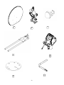
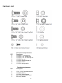
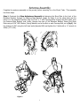
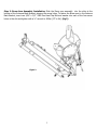
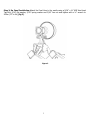
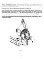
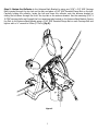
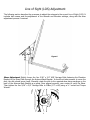
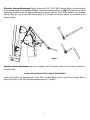
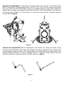
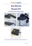
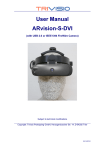
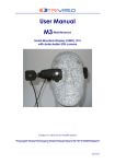
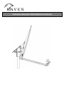
Instruction Manual for 98cm Elliptical Ku Antenna
Caution
This instruction leaflet will assist you in the correct installation of the product. Read it prior to starting any
installation work. Due to the nature of the method of manufacture, there may be sharp edges on metal
components. Be cautious when un-packing and handling antenna parts.
Warning
Assembling dish antennas on windy days can be dangerous. The antenna surface, even in slight winds, creates
strong forces. For example, a 1.0m antenna facing a wind of 32km/h (20 mph) can undergo forces of 269 N
(60 lbs). Be prepared to handle those forces safely at unexpected moments. Do not attempt to assemble,
move, or mount a dish on high wind days or serious, even fatal, accidents may occur. The Vendor is not
responsible or liable for damage or injury resulting from antenna installations.
Warning
Antenna improperly installed or installed to an inadequate structure are very susceptive to wind damage. This
damage can be very serious or even life threatening. The owner and installer assume full responsibility that
the installation is structurally sound to support all loads (weight, wind and ice) and properly sealed against
leaks. The Vendor is not responsible for any damage caused by an antenna due to installations that do not
follow this instruction leaflet.
Danger
WATCH OUT FOR WIRES! Installation of this product near power lines is dangerous. For your own safety,
follow these important safety rules.
1.
Perform as many functions as possible on the ground.
2.
Watch out for overhead power lines. Check the distance to the power lines before starting installation. We
recommend you stay a minimum of 6 meters (20 feet) from all power lines.
3.
Do not install the antenna or mount assembly on a windy day.
4.
If you start to drop the antenna or mount assembly, get away from it and let it fall.
5.
If any part of the antenna or mount assembly comes into contact with a power line, call your local power company.
DO NOT TRY TO REMOVE IT YOURSELF! They will remove it safely.
6.
Properly ground the antenna assembly according to all federal and local electrical codes.
Radiation
Caution
When this antenna is connected to a transmitter, and powered on through interconnection to a satellite
modem, a radiation source can be present. The transmitter will turn on only once a proper receive signal is
obtained. Caution must be used upon completion of alignment to the satellite, and once the installation of the
system has been completed. When the transmitter is operational, keep away a distance of 60 cm (2 feet).
For use in Canada, refer to Health Canada Safety Code 6 - "Limits of Exposure to Radiofrequency Fields at
Frequencies from 10 kHz to 300 GHz". For use in the United States of America see FCC rules (47
C.F.R.1.1310) and OET Bulletin No. 65. For additional information, contact your service provider.
-i-
SITE SELECTION
The first and most important consideration when choosing a prospective antenna site is whether or not the area can provide
an acceptable “look angle” or Line-of-Sight (LOS) at the satellites. A site with a clear, unobstructed view of the southern sky
is necessary. Also, consider obstruction that may occur in the future, such as the growth of trees. Using a Site Survey, select
your antenna site in advance of the installation, so that you will be able to receive the strongest signal available.
As with any other type of construction, a local building permit may be required before installing an antenna. It is the property
owner’s responsibility to obtain all permits. If necessary, modify the installation directions in this document to align with local
building codes.
If the system requires a pole mount installation, obtain information about the underground utilities in the proposed pole
location. Have the appropriate utility company mark the location of any underground telephone wires, storm drains, etc... In
addition; because soils vary widely in composition and load capacity, it may be necessary to consult a local professional
engineer to determine the appropriate foundation design. The pole must be vertical prior to the installation of the antenna.
Use a Spirit Level, measuring the pole in two places 900 apart, or a Pole Level, to verify the pole is vertical. Caution: If the
pole is not vertical, compound angles will make it difficult to align the antenna to the satellite.
All antennas must be installed 5’ above the walking surface or placed in a locked, fenced area!
REQUIRED TOOLS
The installation will require the use of the following tools,
•
1/2” Socket/ 1/2” drive
•
1/2” Open-ended Wrench x2
•
No 6-32 Allen Key
•
Compass
•
Pointing Aid
•
Pointing Meter
•
Torque Wrench (40-180 lbf/in)
Additional Materials
•
Weather grade silicon sealant
•
Approved RG6 Cable
•
Lag screws and washers
•
UV rated Cable ties
PACKAGE CONTENTS
To avoid potential damage, the elliptical antenna should remain in its protective packaging until it is required. Pages one and
two contain a list of package components.
All the packaging is recyclable please dispose of it in a responsible manner.
-ii-
Table of Contents
KEY COMPONENTS................................................................................................................................................................................. III
HARDWARE LIST........................................................................................................................................................................................ I
ANTENNA ASSEMBLY ...............................................................................................................................................................................1
LINE OF SIGHT (LOS) ADJUSTMENT ....................................................................................................................................................6
Key Components
Reflector Box
Number
Description
1
98cm Elliptical Reflector
Number
2
3
4
5
6
7
-
Bracketry Box
Description
Antenna Back Bracket
Ku Feed Horn and Cap Assembly
Boom Arm assembly
Az/El Assembly
Skew Plate
Elevation Handle
Antenna Hardware
-iii-
QTY
1
QTY
1
1
1
1
1
1
1
1
3
2
4
5
7
6
-iv-
Hardware List
QTY
5
5
5
6
5
10
6
Antenna Assembly Hardware
Description
5/16 UNC x 1" carriage bolt
5/16 UNC x 3/4" carriage bolt
5/16 UNC x 3/4” hex head tap bolt
5/16 UNC hex nut
5/16 UNC serrated flange nut
5/16 UNC washer
5/16 UNC spring washer
QTY
Feed Mounting Hardware
Description
2
2
2
2
2
5/16 x ½” UNC hex head tap bolt
5/16 UNC Washer
5/16 UNC Spring Washer
M4 x 10mm Hex Socket Head
M4 Spring Washer
-v-
Antenna Assembly
Complete the antenna assembly on the ground, before mounting it on the Mount Tube. This assembly
has three steps.
Step 1: Construct the Skew Adjustment Assembly by fastening the Skew Plate to the front of the
Elevation Bracket, through the Antenna Back Bracket. Locate the letter A on the skew plate and the
letter A on the elevation bracket. Pass five 5/16” x 1" UNC Carriage Bolts through the skew plate, then
the Antenna Back Bracket, and, finally, through the front of the Elevation Bracket. Secure the Skew
Plate using a 5/16” UNC Washer, Spring Washer, and a Hex Nut on each Carriage Bolt, as in (fig 1). Set
the antenna to 90º using the left hand scale (denoted HN) and tighten the 5 bolts with a ½” wrench to
20Nm (177 in lbf).
Figure 1
1
Step 2: Boom Arm Assembly Installation; Slide the Boom arm assembly into the slots at the
bottom of the Antenna Back Bracket, aligning the screw holes. To fasten the Boom arm to the Antenna
Back Bracket, insert one 5/16” x 3/4 “ UNC Hex Head Tap Bolt and washer into each of the four screw
holes in the slot and tighten with a ½” wrench to 20Nm (177 in lbf) (fig 2).
Figure 2
2
Step 3: Ku Feed Installation; Attach the Feed Horn to the cradle using a 5/16” x ¾” UNC Hex Head
Tap Bolt, 5/16” flat washer, 5/16” spring washer and 5/16” hex nut and tighten with a ½” wrench to
20Nm (177 in lbf) (fig 3).
Figure 3
3
Step 4: Mounting the Antenna. Before attaching the Reflector to the Antenna Bracket, it is
necessary to mount the system on to the Mount Tube. The mount location should be of a sturdy
construction i.e. solid wall or wall studding.
Use a Spirit Level to verify the horizontal and vertical level of the Mount Tube
Taking heed of the safety instructions mentioned at the start of this instruction manual, carry the
Antenna pre-assembly to the Mount Tube location. Slide the Tube Canister onto the top of the Mount
Tube. Secure in place using three 5/16” x 1” UNC Carriage Bolts and three 5/16” UNC Serrated Flange
Nuts in each of the holes in the Tube Canister flanges, then hand-tighten the Flange Nuts (fig 4).
Attention: For vertical mounts, fill all holes with weather-grade silicon sealer before inserting bolts
or screws For horizontal mounts, fill all holes with the appropriate asphalt-based, synthetic-rubber, or acrylic
co-polymer roof sealant
Figure 4
4
Step 5: Fasten the Reflector to the Antenna Back Bracket by using one 5/16" x 3/4" UNC Carriage
Bolts inserted through the top hole on the dish and place a 5/16" UNC Serrated Flange Nut on the bolt.
Carefully holding the reflector, locate the bolt and lower the reflector onto the antenna bracket by
sliding the bolt down through the fork if the top tab on the antenna bracket. Use the remaining 5/16” x
¾”UNC carriage bolts and through the four remaining tabs located on the Antenna Back Bracket. Secure
the Dish to the Antenna Back Bracket using a 5/16" UNC Serrated Flange Nut on each Carriage Bolt and
tighten with a ½” wrench to 20Nm (177lbf.in) (fig 5).
Figure 5
5
Line of Sight (LOS) Adjustment
The following section describes the processes to adjust the antenna to the correct Line of Sight (LOS). It
includes both coarse and fine adjustment of the Azimuth and Elevation settings, along with the skew
adjustment process if required.
Figure 6
Skew Adjustment Slightly loosen the five 5/16” x 3/4" UNC Carriage Bolts fastening the Elevation
Bracket to the Skew Plate through the Antenna Back Bracket. It should not take pressure to move the
dish; the dish should move freely. Manually rotate the dish to the required skew using markings on the
back of the Antenna Back Bracket as a guide. Once aligned correctly, use a meter to verify the Skew.
Then tighten the five 5/16” x 3/4" Carriage Bolts to 20Nm (177 in.lbf) using a ½” socket and Torque
Wrench.
6
Elevation Coarse Adjustment: Slightly loosen the 5/16” X 3/4" UNC Carriage Bolts in the arched slots
at the bottom sides of the Elevation Bracket. Insert the handle as shown in (fig 7). Rotate the handle to
adjust the elevation until the approximate value supplied with the Work Order matches the elevation
setting. With the use of the inclinometer shelf, it is possible to coarsely elevate the antenna to the
desired setting.
Figure 7
Azimuth Coarse Adjustment: Using the compass, set the antenna in the correct direction as listed on
the work order.
DO NOT USE THE REFLECTOR TO ADJUST THE AZIMUTH
Secure this position by tightening the three 5/16” serrated flange nuts on the three Carriage Bolts in
each of the holes in the Tube Canister flanges using a ½” wrench.
7
Azimuth Fine Adjustment: To fine adjust the Azimuth slacken the four 5/16” x 3/4" UNC Carriage
Bolts in the bottom of the Azimuth Base. Next, turn the 2 1/2" x 5/16” UNC Hex Cap Bolt through the
hole on the right side of the Azimuth Base to give you the azimuth angle you require. After verifying the
Azimuth with a compass and a meter, lock down the four 5/16” x 3/4" Carriage Bolts in the bottom of
the Azimuth Base to 20Nm (177 in.lbf) using a ½” socket and Torque Wrench, tightening opposing
corners uniformly (fig 8).
Figure 8
Elevation Fine Adjustment: Make final adjustments to the elevation by rotating the handle, moving
clockwise and anti-clockwise will increase and decrease the setting respectively. After achieving the
correct elevation, tighten the 5/16” x 3/4" Carriage Bolts in the arched slots at the bottom sides of the
Elevation Bracket to 20Nm (177 in.lbf) to lockdown using a ½” socket and Torque Wrench. Once the
elevation is locked off, rotate and remove the handle, as shown in (fig 9).
Figure 9
8