1
SGS
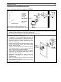
OWNER`S MANUAL
WARNING: If the information in these
instructions is not followed exactly, a fire or
explosion may result causing property
damage, personal injury or death.
FOR YOUR SAFETY: Do not store or use
gasoline or other flammable vapors and
liquids in the vicinity of this or any other
appliance.
Installation and service must be performed
by a qualified installer, service agency or the
gas supplier.
WHAT TO DO IF YOU SMELL GAS:
•
Do not try to light any appliance.
•
Do not touch any electric switch; do not
use any phone in your building.
•
Immediately call your gas supplier from
a neighbor's phone. Follow the gas
supplier’s instructions.
•
If you cannot reach your gas supplier,
call the fire department.
THE INSTALLATION MUST BE IN ACCORDANCE WITH LOCAL CODES OR, IN THE
ABSENCE OF LOCAL CODES, WITH THE CURRENT NATIONAL FUEL GAS CODE
ANSI Z223.1 (USA) OR THE CURRENT CAN/CGA B149 INSTALLATION CODES
(CANADA).
PLEASE KEEP THIS INSTRUCTIONS MANUAL
FOR FUTURE REFERENCE
S B I , 1700 LÉON-HARMEL, QUÉBEC, (QUÉBEC), CANADA, G1N 4R9
Tel : ( 418 ) 527-3060
Fax : ( 418 ) 527-4311
www.drolet.ca
010517/45047A_feb 03
SGS GAS STOVES
1
TABLE OF CONTENTS
GENERAL INFORMATION.................................................................................................................................................... 2
WARNINGS ........................................................................................................................................................................... 2
TECHNICAL SPECIFICATIONS ............................................................................................................................................ 3
SGS Dimensions ............................................................................................................................................... 3
SGS II Dimensions ............................................................................................................................................ 4
Burner................................................................................................................................................................ 5
Gas Valve.......................................................................................................................................................... 5
Pressure Adjustments ................................................................................................................................... 5
Available Options .............................................................................................................................................. 5
INSTALLATION ..................................................................................................................................................................... 6
Safety Notice ..................................................................................................................................................... 6
Positioning the Stove ........................................................................................................................................ 6
Clearances to combustibles .............................................................................................................................. 7
Direct Vent Installation ...................................................................................................................................... 8
Critical Length of Venting Pipes .................................................................................................................... 8
Terminal Vent Location ................................................................................................................................. 9
Installation of Drolet Wall Venting Kits ........................................................................................................ 10
Vented Gas Stove Installation ("B-Vent")........................................................................................................ 12
Critical Length of Venting Pipes .................................................................................................................. 12
Stove conversion for a "B-Vent" installation only ........................................................................................ 13
Gas Piping....................................................................................................................................................... 15
Logs Installation .............................................................................................................................................. 15
Ember Kit Installation ...................................................................................................................................... 16
Pedestal cover (model SGS and SGS II)........................................................................................................ 16
OPERATING YOUR STOVE ............................................................................................................................................... 17
For your safety ................................................................................................................................................ 17
Lighting Instructions ........................................................................................................................................ 17
Shut down Instructions.................................................................................................................................... 18
Optional Wall Thermostat (AC05558) ............................................................................................................. 18
The benefits of installing a blower................................................................................................................... 19
Optional Thermodisc (AC05530) .................................................................................................................... 20
MAINTENANCE INSTRUCTIONS ....................................................................................................................................... 21
Yearly maintenance ........................................................................................................................................ 21
Glass door ....................................................................................................................................................... 21
Cleaning ...................................................................................................................................................... 21
Repairing ..................................................................................................................................................... 21
Burner.............................................................................................................................................................. 22
Removing the Burner .................................................................................................................................. 22
Burner Installation ....................................................................................................................................... 22
Air Shutter Adjustment (under the burner) .................................................................................................. 22
OPTIONS............................................................................................................................................................................. 23
REMPLACEMENT PARTS .................................................................................................................................................. 23
LIMITED WARRANTY ......................................................................................................................................................... 24
SGS GAS STOVES
2
GENERAL INFORMATION
The SGS GAS STOVE is a high-efficiency gas appliance with a maximum input rating of 28 500 BTU/h (8,4
kW) with natural gas or 26 000 BTU/h (7,6 kW) with propane. It features an adjustable millivolt valve and a
constant pilot independent of any electrical source. Your appliance will therefore continue to heat your house
in the event of a power failure. You can set the height of the flame to your liking by turning the adjusting knob.
For increased efficiency, we offer as an option an ultra quiet tangential blower with speed control. An optional
thermostat is also available for automatic room temperature control.
This appliance must be connected to a venting system. Read these instructions and consult your local building
authorities before installing this appliance. In the case of a direct vent installation use only with Simpson
(Dura-Vent), Security Chimneys International (Secure Vent), Selkirk (Direct-Temp) or Drolet Direct Vent Kit.
KEEP THESE INSTRUCTIONS FOR FUTURE REFERENCE
This gas stove has been tested by Intertek Testing Services according to CGA-2.33-M00 and CAN/CGA-2.17M91 for Canada and ANSI Z21.88-2000.
It is mobile home approved in the case of a direct vent installation only. This appliance must be installed in
accordance with the current Standard Mobile Homes, CAN/CSA Z240 MH OR CAN/CSA Z240RV,
RECREATIONAL VEHICLES or with the Manufactured Home Construction and Safety Standard, Title 24
CFR, Part 3280, or when such a standard is not applicable, the current Standard for Fire Safety Criteria for
Manufactured Home Installations, Sites, and Communities, ANSI/NFPA 501A or with the current Standard for
RECREATIONAL VEHICLES, ANSI A119.2/NFPA 501C.
The unit can be installed in a range of altitude from 0 to 4 500 ft (0-1 370 m) in Canada when using natural
gas. For propane gas, the valve need to be adjusted for altitudes between 2000' and 4500' (610-1370m). In
USA, see gas codes for operating above 2000 ft.
WARNINGS
•
•
•
•
•
•
•
•
•
•
Installation should be done by a qualified installer.
Do not burn wood or any other material in this appliance.
Hot when in operation. Keep children, furniture, clothing and flammable material away
from the appliance.
Inform adults and children to the hazard of high surface temperatures and that they
should stay away to avoid burns or clothing ignition.
Young children should be supervised when they are in the same room as the appliance.
The appliance should be inspected before use and at least once a year by a qualified
service person. More frequent cleaning may be required due to excessive lint from
carpeting, bedding material, etc.
It is imperative that the control compartments, burners and circulating air passageways
be kept clean.
Do not modify this appliance.
The openings in the gas stove pedestal should never be blocked.
Provide adequate accessibility clearances for servicing and proper operation.
SGS GAS STOVES
3
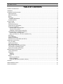
TECHNICAL SPECIFICATIONS
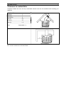
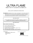
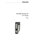
SGS Dimensions
Dimensions
Height : 27 3/4 po / 706 mm
Width : 24 1/2 po / 621 mm
Depth : 23 po / 585 mm
Ceramic Glass
8 3/4 po x 16 5/8 po
222 mm x 422 mm
Weight
115 lbs / 53 kg
Color
Metallic black
Clearances to Combustibles
• Back :
7 po
180 mm
• Side :
7 po
180 mm
• Corners : 4 po
100 mm
• Top :
36 po 915 mm
• Combustible Floor Note 1
TOP VIEW
Note 1 : Your stove has been successfully certified while installed on
a wood floor. Do not install your stove on carpeted floor. Choose a
ceramic tile or wood floor instead.
FRONT VIEW
SIDE VIEW
SGS GAS STOVES
4
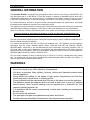
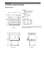
SGS II Dimensions
Dimensions
Height : 27 3/4 po / 706 mm
Width : 24 1/2 po / 621 mm
Depth : 23 po / 585 mm
Ceramic Glass
Front :
11 1/2 po x 12 1/2 po
292 mm x 318 mm
Side :
4 3/8 po x 12 1/2 po
111 mm x 318 mm
Weight
122 lbs / 56 kg
Color
Metallic black
Clearances to Combustibles
• Back :
7 po
180 mm
• Side :
7 po
180 mm
• Corners : 4 po
100 mm
• Top :
36 po 915 mm
• Combustible Floor Note 1
Note 1 : Your stove has been successfully certified while installed on
a wood floor. Do not install your stove on carpeted floor. Choose a
ceramic tile or wood floor instead.
TOP VIEW
FRONT VIEW
SIDE VIEW
SGS GAS STOVES
5
Burner
Maximum Input, BTU/h (kW)
Inlet Pressure Inch WC (kPa)
Manifold Pressure Inch WC (kPa)
Burner orifice, ∅ :
minimum :
maximum :
minimum :
maximum :
minimum :
maximum :
Natural Gas
19 000
(5,6)
28 500
(8,4)
5,0
(1,3)
7,0
(1,8)
1,6
(0,4)
3,5
(0,9)
#36 DMS
Propane LP
20 000
(5,9)
26 000
(7,6)
11,0
(2,8)
14,0
(3,5)
6,3
(1,7)
10,0
(2,5)
#52 DMS
Gas Valve
S.I.T. Controls USA
Honeywell
Natural Gas
Model SIT 0.820.634 Nova mV
VS8420E8001B
Propane LP
Model SIT 0.820.633 Nova mV
VS8420E8001B
VALVE FOR A SAFE USE. THE GAS CONTROL VALVE
THE PILOT FLAME AND CAPTURED BY THE THERMO-
YOUR STOVE IS EQUIPPED WITH A SOPHISTICATED GAS CONTROL
OPERATES WITHOUT ELECTRICITY DUE TO THE ENERGY GIVEN BY
GENERATOR. (ALSO CALLED THERMOPILE). THE ADMISSION OF THE GAS FUEL TO THE BURNER IS DONE ONLY UNDER
SAFE CONDITIONS.
Pressure Adjustments
For USA, above 2000 ft (610 m), see gas codes to adjust the valve operating pressure.
• Adjustments to the valve assembly must be performed by a qualified service person.
• The appliance and its individual shutoff valve must be disconnected from the gas supply piping system
during any pressure testing of that system at test pressures in excess of ½ psi (3.5 kPa);
• The appliance must be isolated from the gas supply piping system by closing its individual manual shutoff
valve during any pressure testing of the gas supply piping system at test pressures equal to or less that ½
psi (3.5 kPa);
NATURAL GAS
The inlet supply or line pressure must be a minimum of 5" WC and a maximum of 7" WC. The orifice has a
#36 DMS hole.
ELEVATION
INPUT RATING
0-4500 ft (0-1400m)
28 500 BTU/h
(8.4 kW)
over 4500 ft (1400 m)
28 500 BTU/h
(8.4 kW) less 4% per 1000 ft (300 m)
or reduce manifold pressure by 0.25 INWC per 1000 ft (300 m)
PROPANE GAS
The inlet supply or line pressure must be a minimum of 11” WC and a maximum of 14” WC. The orifice has
a #52 DMS hole.
ELEVATION
INPUT RATING
0-2000 ft (0-610 m)
26 000 BTU/h
(7.6 kW) Manifold pressure 10 " WC
2000-4500 ft (0-1400 m)
24 200 BTU/h
(7.0 kW) Manifold pressure 8.5 " WC
over 4500 ft (1400 m)
24 200 BTU/h
(7.6 kW) less 4% per 1000 ft (300 m)
or reduce manifold pressure by 1" WC per 1000 ft
NOTE : The input rating should always be checked when running this appliance for the first time. To do this,
verify inlet valve pressure and manifold pressure. Adjust manifold pressure to meet the value range as
indicated in the burner characteristics table.
Available Options
Blower Kit AC02050
• Ultra quiet tangential blower;
• Variable speed control.
Thermo Switch Kit AC05530
• Thermo switch starting the blower at 110 OF (43 OC) and stopping it at 90 OF (32 OC)
Thermostat Kit AC05558
SGS GAS STOVES
6
INSTALLATION
Before starting any installation, make sure you know :
• Where you run your gas line ;
• What type of venting kit you need ;
• Where you run your venting pipes ;
• Where you install the terminal vent in respect with installation code ;
• Clearances to combustibles ;
• Length of horizontal and vertical runs of venting pipes.
Safety Notice
•
•
•
•
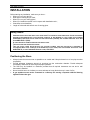
IMPROPER INSTALLATION MAY RESULT IN A HOUSE FIRE. FOLLOW INSTALLATION DIRECTIONS. INSTALLATION MUST
BE DONE IN ACCORDANCE WITH LOCAL BUILDING CODES OR, IN THE ABSENCE OF LOCAL CODES, WITH CURRENT
CAN/CGA B 149 INSTALLATION CODES FOR GAS APPLIANCES (CANADA) AND CURRENT NATIONAL FUEL GAS
CODE ANSI Z223.1 (USA).
A QUALIFIED INSTALLER MUST PERFORM THE INSTALLATION.
THIS GAS STOVE MUST BE VENTED OUTSIDE.
THIS GAS STOVE, WHEN INSTALLED WITH AN OPTIONAL BLOWER, MUST BE ELECTRICALLY GROUNDED IN
ACCORDANCE WITH LOCAL CODES OR, IN THE ABSENCE OF LOCAL CODES, WITH THE NATIONAL ELECTRICAL CODE,
ANSI/FPA 70, OR THE CANADIAN ELECTRICAL CODE, CSA C22.1.
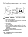
Positioning the Stove
•
•
•
•
•
Always locate the stove as near as possible to an outside wall. Keep horizontal run of vent pipe as short
as possible;
Provide adequate clearances around air openings into the combustion chamber. Provide adequate
accessibility clearances for servicing and proper operation.
The SGS may be installed in a bedroom provided that all required clearances are met and a wall
thermostat is installed.
Never install the stove in a hallway or near a staircase as it may block the way in case of a fire.
A gas appliance must not be connected to a chimney flue serving a separate solid-fuel burning
appliance other then gas.
SGS GAS STOVES
7
Clearances to combustibles
Clearance between the stove and any combustible material must also be maintained while installing your
appliance.
CLEARANCE
Back (in)
Side (in))
Corners (in)
Top (in)
Front (in)
Pipe (in)
Floor
7
7
4
36
36
1½
Combustible Note 1
Corner Installation
Direct Installation
Note 1 : Your stove has been successfully certified while installed on a wood floor. Do not install your stove on carpeted
floor. Choose a ceramic tile or wood floor instead.
SGS GAS STOVES
8
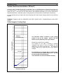
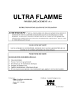
Direct Vent Installation
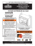
Critical Length of Venting Pipes
The following table shows the maximum length to
be respected while installing your appliance with
venting pipes (4"X6 5/8") from Simpson DuraVent, Security Chimneys International (Secure
Vent) or Selkirk (Direct-Temp) only.
30
29
28
27
The maximum number of elbows in your venting
system is three (3) 45° elbows or one (1) 45° elbow
and two (2) 90° elbows.
26
25
24
23
Example (the doted line on the table):
The example on the table is showing a possible
installation with five (5) feet of horizontal run and
fifteen (15) feet of vertical rise. The venting system
starts with a 45° elbow at the stove level, one (1) 45°
elbow at five (5) feet and an other one at ten (10) feet.
The maximum number of three (3) 45° elbows is
reached. Take note that this installation must start
with the restrictor ring "A" as shown on the table.
22
21
20
Allowed Installation
Zone with restrictor
ring "A"
Vertical length (ft)
19
18
17
16
15
14
Example
13
12
11
The restrictor ring must be inserted between two
pipe sections.
10
9
Allowed Installation
Zone with restrictor
ring "B"
8
7
6
No horizontal run is allowed with a negative slope.
You need a minimum upward slope of a ¼" per
foot for every length of horizontal pipe.
5
4
3
If there is an enclosure of the venting pipes it
must be a minimum of 9" X 9".
2
1
0
0
1
2
3
4
5
6
7
Horizontal length (ft)
8
9
10
If your venting system is ending over the line from
twelve (12) feet to sixteen (16) feet on the table,
you must use the restrictor ring "A" when going
out of the stove to the venting system.
SGS GAS STOVES
9
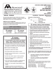
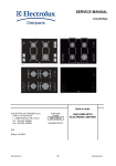
Terminal Vent Location
Your SGS stove vents through a vent terminal installed on the roof or on the outside of any exterior wall of
your house. Many restrictions apply to the vent terminal location that should be considered before locating
your stove. The following drawing presents a summary of most of these restrictions.
LÉGENDE
A. 12’’
B. 12’’
C. 12’’
D. 18’’
Clearance above grade, veranda, porch, deck or balcony
Clearance to window or door that may be opened
Clearance to permanently closed window
Vertical clearance to ventilated soffit located above the terminal within a horizontal distance of 2 feet (60
cm) from the center-line of terminal (direct or corner installation)
24’’ Vertical clearance to ventilated soffit (Basement installation)
E. 12’’ Clearance to unventilated soffit, (straight out or corner installation)
24’’ Clearance to unventilated soffit, (Basement installation)
F. 12’’ Clearance to outside corner
G. 12’’ Clearance to inside corner
H. 36”Clearance to each side of the centerline extended above the meter / regulator assembly to a maximum
vertical distance of 15ft (4.57M)
I. 36’’
Clearance to service regulator vent outlet
J. 12’’
Clearance to non-mechanical air supply inlet to building or the combustion air inlet to any other appliance
K. 72’’ Clearance to a mechanical air supply inlet
L. 84’’ Clearance above paved sidewalk or a paved driveway located on public property. A vent shall not terminate
directly above a sidewalk or paved driveway which is located between two single family dwellings and
serves both dwelling
M. 12’’ Clearance under veranda, porch, deck, or balcony. Only permitted if veranda, porch, deck, or balcony is
fully open on a minimum of 2 sides beneath the floor.
Local codes or regulations may require different clearances.
When the vent terminal is accessible, a certified guard shall be installed around the terminal.
The vent terminal may not be recessed into the wall or siding.
The vent terminal shall not be:
•
Within 3 ft. of a building mechanical air supply;
•
Less than 12 inches from a perpendicular wall;
•
Under a window that pivots open.
In addition, in a structure with three walls and a roof, the vent terminal should not be installed if:
•
The distance between the two sidewalls is less than 72";
•
The roof exceed the walls by more than 24".
SGS GAS STOVES
10
Installation of Drolet Wall Venting Kits
Direct And Corner Vent Kit Installation AC02000:
Coaxial 4" X 6 5/8" rigid vent system with black
finish includes :
1.
45° Elbow
2.
24" Pipe
3.
90° Elbow
4.
24" Pipe
5.
Adjustable pipe
6.
Wall thimble
cover
7.
Wall thimble
8.
Snorkel
termination cap
Restrictor
ring B
Note: Restrictor ring B is supplied with your
stove. Insert the ring between section 1 and 2.
1. Place the stove at the desired location ;
2. Install temporarily pipes #1, #2, #3 and #4 in order to mark the opening on the exterior wall. For a corner
installation, rotate elbow #3 so it is facing the exterior wall.
NOTE : Horizontal run should have a upward slope of at least ¼" per foot.
3. Make a 9 1/2’’ x 9 1/2’’ inch opening in the wall to
install the wall thimble (#7a and 7b);
4. If necessary, cut the wall thimble (#7a and 7b)
according to the wall thickness. Slide part #7a and 7b
into place and secure with 8 wood screws #10 x 1 ½";
5. Install and secure the snorkel termination cap (#8)
with 1 ½’’ wood screws;
6. Install the wall thimble cover #6 using pipe #5 to make
sure you are centered. Secure with 4 black finishing
screws. Remove pipe #5;
7. Install the 45° elbow on the stove. Make sure that the
6 5/8" female and the 4" male ends are toward the
stove. Everything should tightly fit together.
NOTE : Make sure that all pipe junctions are properly
sealed with high temperature sealer paste (700°F to
1050°F) included in your stove;
8. Repeat step 7 for parts #2, 3, 4 and 5. Pipe #5 is
adjustable to facilitate the connection to the
termination cap;
9. Seal the termination cap to the exterior wall to prevent
water leakage into the house ;
10. Secure the stove to the floor using the fixation holes on
each side of the pedestal.
SGS GAS STOVES
11
Direct Vent Kit for Basement Installation AC02010:
Coaxial 4" X 6 5/8" rigid vent system with
black finish includes :
1- 45° Elbow
2- Two 24" Pipes
3- 90° Elbow
4- 24" Pipe
5- Adjustable pipe
6- Wall thimble cover
7- Wall thimble
8- Snorkel termination cap
Note: Restrictor ring B is supplied with
your stove. Insert the ring between
section 1 and 2.
Restrictor
ring B
1. Place the stove at the desired location ;
2. Install temporarily pipes #1, #2, #3 and #4 in order to mark the opening on the exterior wall. For a corner
installation, rotate elbow #3 so it is facing the exterior wall.
NOTE : Horizontal run should have a upward slope of at least ¼" per foot.
3. Make a 9 1/2’’ x 9 1/2’’ inch opening in the wall to
install the wall thimble (#7a and 7b);
4. If necessary, cut the wall thimble (#7a and 7b)
according to the wall thickness. Slide part #7a and 7b
into place and secure with 8 wood screws #10 x 1 ½";
5. Install and secure the snorkel termination cap (#8)
with 1 ½’’ wood screws;
6. Install the wall thimble cover #6 using pipe #5 to make
sure you are centered. Secure with 4 black finishing
screws. Remove pipe #5;
7. Install the 45° elbow on the stove. Make sure that the
6 5/8" female and the 4" male ends are toward the
stove. Everything should tightly fit together.
NOTE : Make sure that all pipe junctions are properly
sealed with high temperature sealer paste (700°F to
1050°F) included in your stove;
8. Repeat step 7 for parts #2, 3, 4 and 5. Pipe #5 is
adjustable to facilitate the connection to the
termination cap;
9. Seal the termination cap to the exterior wall to prevent
water leakage into the house ;
10. Secure the stove to the floor using the fixation holes on
each side of the pedestal.
SGS GAS STOVES
12
Vented Gas Stove Installation ("B-Vent")
Instead of using a standard B-vent pipe it is possible to use a 4" flexible aluminum chimney lining system into
an existing chimney. The existing chimney must be a code complying masonry or listed fuel burning chimney
system: ‘B’ vent, ‘L’ vent UL103 or ULC S629. Refer to the installation standards in your area or CAN/CGA B149 AND ANSI Z223-1 standards (under "venting systems") and instructions of flexible pipe manufacturer.
It is very important that you respect the critical horizontal and vertical length of piping specified in the following
diagram.
WARNING: ALWAYS USE AN APPROVED GAS PIPE. NEVER USE A CONVENTIONAL 6-INCH PIPE
ALONE.
Vertical length (ft)
Critical Length of Venting Pipes
46
45
44
43
42
41
40
39
38
37
36
35
34
33
32
31
30
29
28
27
26
25
24
23
22
21
20
19
18
17
16
15
14
13
12
11
10
9
8
7
6
5
4
3
2
1
0
Allowed
Installation Zone
The maximum number of elbows in your venting
system is two (2) 90° elbows. Each of the 90°
elbows can be replaced by two (2) 45° elbows.
Example (the doted line on the table):
The example on the table is showing a possible
installation with seven (7) feet of horizontal run and
twenty-one (21) feet of vertical rise. The maximum
number of two (2) 45° elbows and one (1) 90° elbow is
reached.
Example
0
1
2
3
4
5
6
No horizontal run is allowed with a negative slope.
You need a minimum upward slope of a ¼" per foot
for every length of horizontal pipe.
The termination cap must be installed vertically.
7
8
Horizontal length (ft)
9
10
SGS GAS STOVES
13
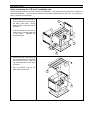
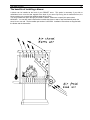
Stove conversion for a "B-Vent" installation only
The following instructions are not for a direct vent installation. Your Drolet stove is coming to you ready for a
direct vent installation. You can buy a conversion kit to be able to install it as a "B-Vent" unit. To convert your
stove, just follow the instructions:
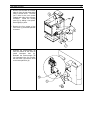
1. Remove the decorative panels (1)
by unscrewing the two screws at
the back of the stove. Simply
slide the panel toward the front of
the stove.
2. Unscrew and remove the two air
intake traps (2) located each side
of the stove.
Reinstall the
decorative panel.
3. Remove the top of the stove (3)
by unscrewing the two screws at
the back of the stove. Slide the
top toward the back of the stove
to remove.
4. Clip the restrictor ring (4) into
place to bloc the air inlet.
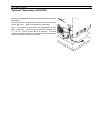
SGS GAS STOVES
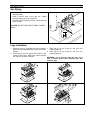
5. Remove and discard the metallic
plate (6) from the rear heat shield
using a screw driver. Unscrew
just a little bit the two screws
located each side of the chimney
connector.
Install the venting
hood (5) by sliding it into place.
Screw tightly in place.
6. Remove the four screws of the
valve cover (7) and slide upwards
to remove.
7. Unscrew the thermocouple (8)
from the bottom of the valve to
install
interrupter
bloc
(9).
Reinstall the thermocouple (8)
into interrupter bloc (9). Connect
the two wires (10) from the hood
to the interrupter bloc (9).
14
SGS GAS STOVES
15
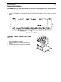
Gas Piping
• Route a 3/8" minimum NPT iron pipe gas line to the
desired location.
• Install a shutoff valve to the gas line. Tighten
securely using a pipe joint compound.
• Check the gas line piping for leaks. Use a soap and
water solution.
CAUTION: DO NOT USE OPEN FLAME TO CHECK
LEAKS.
Logs Installation
1. Place the rear log (1) against the rear log holders. 3. Place log (4) on top of logs (1) and (2) in the
Make sure grooves behind the log line up with the
matching grooves.
4. Place log (5) on top of logs (1) and (3) in the
holders.
2. Place logs (2) and (3) against the holders in the
matching grooves.
middle of the burner. Make sure grooves behind
the logs line up with the holders.
WARNING : If you need to clean the logs, do it
with a flexible paint brush otherwise you will
break the logs.
SGS GAS STOVES
16
Ember Kit Installation
CAUTION: Blocking gas ports with rock wool will result in poor light-up performance, delayed ignition,
affect flame aspect and form carbon deposit on logs.
1. Place some pieces of rock wool fibers approximately 1/2" large behind the front gas ports.
2. Light the stove. Modify the configuration of the rock wool near the gas ports until you reach the desired
effect.
Pedestal cover (model SGS and
SGS II)
1. Screw the stove on the floor using the fixation
holes each side of the pedestal;
2. Slide the pedestal cover over the pedestal from
the front;
3. Place the back cover on the pedestal cover and
secure with the supplied screws.
SGS GAS STOVES
17
OPERATING YOUR STOVE
For your safety
ATTENTION :
• A QUALIFIED INSTALLER MUST PERFORM INSTALLATION OF THE APPLIANCE, VENTING, PIPING AND ADJUSTMENTS.
• DURING OPERATION, THIS STOVE IS HOT. DO NOT TOUCH. KEEP CHILDREN, CLOTHING, FURNITURE AND FLAMMABLE
MATERIALS AWAY.
• Make sure your stove is in good condition. Verify that the door close perfectly and that all controls work as
per specifications. Vent must be in perfect condition and sealed.
• Make sure your stove has been fabricated in respect with the type of gas you are using. Refer to the rating
plate installed on the back of your stove.
• The appliance and its individual shutoff valve must be disconnected from the gas supply piping system
during any pressure testing of the system at test pressures in excess of ½ psi (3.5 kPa); The appliance
must be isolated from the gas supply piping system by closing its individual manual shutoff valve during
any pressure testing of the gas supply piping system at test pressures equal to or less that ½ psi.
• Do not use this appliance if any part has been under water. Immediately call a qualified service technician
to inspect the appliance and to replace any part of the control system and any gas control, which has been
under water. Make sure that there are no obstructions in the air intake or venting system.
• Clear the immediate area of combustible materials, gasoline, and other flammable liquids and vapors.
• Make sure that the logs are in the right position.
Lighting Instructions
During the first few hours of operation, the appliance will release an odor. This is caused by the burning off of
residual oils used in the manufacturing process and by the curing of the high heat paint. Open a window to get
fresh air inside the house. The ceramic glass window may require cleaning after this initial fire. Please read
the instructions on cleaning in the MAINTENANCE section before doing so.
First Lighting
WARNING : If you do not follow these lighting instructions exactly, a fire or explosion may result causing
property damage, personal injury, or death.
• Make sure the gas control knob is turned to the "OFF" position. If it is not, press the knob slightly and turn it
clockwise 3 to the "OFF" position. Do not force the gas control knob. If the gas control was in the "ON"
position, you should wait 5 minutes before trying to re-light the stove.
• If you smell gas, STOP and follow instructions on the COVER page.
• Locate the pilot on the right side under log #1.
• Push in and turn gas control knob counterclockwise 4 to the "pilot" position.
• Press gas control knob in and hold. Immediately push the red igniter button repeatedly until pilot flame
ignites. Continue holding in the control knob for 5 to 10 seconds, and then release it. If the pilot flame goes
out, repeat this step.
Note: you might have to push the igniter (red button) a couple of times before getting a pilot flame.
• Push and turn gas control knob counterclockwise 4 to the "ON" position. The burner flame will light.
IMPORTANT NOTE:
The gas valve is equipped with a thermopile (thermo generator) and a thermocouple. The thermopile while
warm up by the pilot flame supplies the necessary energy to the operation of the gas control valve. As
long as there’s no flame failure, the valve let the gas flowing to the stove.
Let your stove cool down between two lightings: If you attempt to relight your appliance while the
thermocouple is still warm, the control valve will not let the gas flow to the burner. Wait a few minutes to
cool the thermocouple down.
SGS GAS STOVES
18
Shut down Instructions
To turn the burner OFF but leave the pilot open
•
Push in and rotate the gas control knob clockwise 3 to "PILOT" position. Do not force.
To turn the pilot OFF
•
Push in and rotate the gas control knob clockwise 3 to "OFF" position. Do not force.
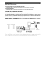
Optional Wall Thermostat (AC05558)
Note: Use only a millivolt thermostat to prevent any permanent damage to the valve.
The optional wall thermostat will automatically keep your room at an even temperature. You need to choose a
convenient location for the thermostat. Remember that it should be at least 10 feet from the stove and away
from direct radiation of the fire. Run the correct gauge wire (see table) from the valve to the thermostat and
wire as shown in the diagram.
REMOVE THE BLUE JUMPER BETWEEN TH & TPTH SCREWS ON THE GAS VALVE. PLUG THE
THERMOSTAT WIRES (TH & TPTH).
DISTANCE
20 pi
30 pi
40 pi
50 pi
DIAMETRE
18GA
16GA
14GA
12GA
Thermocoupl
To use your SGS with the wall thermostat, follow the lighting procedure and set the gas control to the ON
position. Simply set your wall thermostat to a comfortable temperature and the stove will do the rest.
SGS GAS STOVES
19
The benefits of installing a blower
A blower can be installed at the back of your DROLET stove. This option is necessary if you wish to
redistribute into a room the heat trapped at the back of your stove. By forcing hot air toward the front, the
blower enables you to extend the radiation power of your stove.
You can purchase this option through your DROLET dealer. Make sure to specify this part number:
#AC02050. You can also install a thermodisc to enable the blower to start or stop automatically when the
stove is hot or too cold. The thermodisc part number is AC05530. Installation instructions are supplied with
the blower and the thermodisc.
SGS GAS STOVES
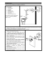
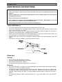
Optional Thermodisc (AC05530)
Follow the installation instructions included with the optional
thermodisc.
The fixation holes are located at the back of the stove on the
lower right corner. Refer to the drawing on this page.
Note : The blower will start when the temperature at the
back of the stove, where the air is circulated, reaches 110
O
F (43 OC). This can take 30 to 60 minutes. The time
varies depending of the burner intensity and the temperature
of the room where the stove is located.
20
SGS GAS STOVES
21
MAINTENANCE INSTRUCTIONS
WARNINGS :
• TURN OFF THE GAS WITH THE SHUTDOWN VALVE AND DISCONNECT THE ELECTRICAL POWER BEFORE SERVICING THE
APPLIANCE.
• LABEL ALL WIRES PRIOR TO DISCONNECTION WHEN SERVICING CONTROLS. WIRING ERRORS CAN CAUSE IMPROPER
AND DANGEROUS OPERATION.
• VERIFY PROPER OPERATION AFTER SERVICING.
• DO
NOT OPERATE THE STOVE WITH THE GLASS REMOVED, CRACKED OR BROKEN.
SHOULD BE DONE BY A LICENSED OR QUALIFIED SERVICE PERSON.
REPLACEMENT
OF THE GLASS
• THE GLASS MUST BE HANDLED WITH CARE, NO STRIKING OR SLAMMING SHUT.
Yearly maintenance
•
•
•
•
•
•
The venting system and the gas stove should be inspected at least once a year.
The control compartment, air circulating passages, firebox, logs and burner should be cleaned at least
once a year by vacuuming or brushing.
Check the pilot flame to see if it is adjusted properly (as shown below). Readjust the pilot flame if
necessary or clean the pilot orifice if readjustment is not possible.
Check the burner for flame lifting or for unusual flame pattern. If necessary, clean the burner orifice. For
more information, see “Adjustments” in the INSTALLATION section.
Keep the area clear and free from combustible materials, gasoline and other flammable vapors and
liquids.
In the case of a "B-Vent" installation, check the hood thermo switch.
Glass door
Cleaning
•
•
•
•
Never clean this glass with abrasive cleaners;
Use only a cleaner recommended by your dealer;
Never clean the glass while it is still hot;
Do not operate the stove with the glass broken or removed.
Repairing
•
•
•
Ask your Drolet dealer to provide you with the appropriate replacement glass (ceramic glass (Robax)
5mm (3/16")). Do not use substitute materials.
To replace the glass, remove the screws retaining the glass moldings inside the door. Remove the
moldings and replace the damaged piece with a new one. Perform the procedure backwards after
replacing. When replacing the glass, you should change the glass gasket to make sure you keep it
sealed.
If the gasket is damaged, replace it with an identical one. To get a new gasket, refer to your DROLET
dealer.
SGS GAS STOVES
22
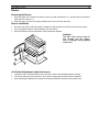
Burner
Removing the Burner
•
•
Open the glass door. Remove the burner contour (2) and the deflector (3). Unscrew the two screws on
each side of the burner (1).
Slide the burner out from the ventury towards the left. Get it out from the stove.
Burner Installation
•
•
•
Get the burner back in place and push it towards the right until the main orifice enters into the ventury;
The o-ring gasket must be in place between the main orifice;
Screw the burner back into the bottom of the combustion chamber.
WARNING :
The main orifice burner must be
well inserted into the ventury
tube, or damages during lighting
could occur.
Air Shutter Adjustment (under the burner)
•
•
•
Loosen the screw of the air shutter on the ventury in order to increase/decrease the opening.
The factory setting for the air shutter is 3/16" open for natural gas, and fully open for propane.
After operating the appliance 30 minutes, the flames should have turned into nice yellow color.
SGS GAS STOVES
23
OPTIONS
DESCRIPTION
Millivolt Wall Thermostat
Tangential blower with variable speed control
Direct Vent Kit and Corner Installation
Direct Vent Kit Basement Installation
PART #
AC05558
AC02050
AC02000
AC02010
REMPLACEMENT PARTS
DESCRIPTION
5 logs set
Burner (natural gas and propane)
Orifice natural gas
Orifice propane gas
Pilot SIT natural gas
Pilot SIT propane gas
Thermocouple SIT
Piezo
Natural gas valve Nova SIT 820
Propane gas valve Nova SIT 820
Thermo Switch
PART #
AC05791
SE09011-02
9071
9071-01
49103
49106
49122
49128
49133
49126
44044
SGS GAS STOVES
24
1700, rue Léon-Harmel, Québec (Québec) G1N 4R9
tel. : (418) 527-3060 fax : (418) 527-4311
e-mail : [email protected] web site : www.drolet.ca
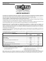
LIMITED WARRANTY
The warranty of the manufacturer extends only to the original consumer purchaser and is not transferable. This warranty covers brand
new products only, which have not been altered, modified nor repaired since shipment from factory. Proof of purchase (dated bill of
sale), model name and serial number must be supplied when making any warranty claim to your Drolet dealer.
This warranty applies to normal residential use only. Damages caused by misuse, abuse, improper installation, lack of maintenance,
over firing, negligence or accident during transportation are not covered by this warranty.
This warranty does not cover any scratch, corrosion or discoloration caused by over firing, abrasives or chemical cleaners. Any defect
or damage caused by the use of unauthorized parts or others than original parts void this warranty.
An authorized qualified technician must perform the installation in accordance with the Instructions supplied with this product and all
local and national building codes. Any service call related to an improper installation is not covered by this warranty.
Returned products are to be shipped prepaid to the manufacturer for investigation. If a product is found to be defective, the
manufacturer will repair or replace such defect and reasonable transportation fees will be refunded. Repair work covered by the
warranty, executed at the purchaser domicile by an authorized qualified technician requires the prior approval of the manufacturer.
Labour cost and repair work to the account of the manufacturer are based on predetermined rate schedule and must not exceed the
wholesale price of the replacement part.
The manufacturer at its discretion may decide to repair or replace any part or unit after inspection and investigation of the defect. The
manufacturer may, at its discretion, fully discharge all obligations with respect to this warranty by refunding the wholesale price of any
warranted but defective parts
The manufacturer shall in no event be responsible for any special, indirect, consequential damages of any nature, which are in excess
of the original purchase price of the product.
WARRANTY APPLICATION
DESCRIPTION
PARTS
LABOUR
Combustion chamber (weldings only)
5 years
5 years
Stainless baffle
5 years
1 year
Carbon Steel baffle
2 years
1 year
Gas Valve, piezo, thermopile, thermoswitch, burner
1 year
1 year
N/A
N/A
Ceramic glass (thermal breakage only)
5 years
N/A
Paint, gasket, blower, Blower thermoswitch and rheostat
1 year
N/A
Gold plating (tarnishing)
5 years
N/A
Logs
Shall your unit or a components be defective, contact immediately your Drolet dealer. Prior to your call make sure you have the
following information necessary to your warranty claim treatment:
•
•
Your name, address and telephone number;
Bill of sale, dealer’s name;
•
Serial number and model name as indicated on the
nameplate fixed to the back of your unit;
•
Nature of the defect and any relevant information.
Before shipping your unit or defective component to our plant, you must obtain from your Drolet dealer an Authorization
Number. Any merchandise shipped to our plant without authorization will automatically be refused and returned to sender.