1
dsPIC30F6010A/6015
dsPIC30F6010A/6015 Rev. A2/A3 Silicon Errata
The dsPIC30F6010A/6015 (Rev. A2/A3) samples that
you have received were found to conform to the
specifications and functionality described in the
following documents:
Silicon Errata Summary
• DS70157 – “dsPIC30F/33F Programmer’s
Reference Manual”
• DS70150 – “dsPIC30F6010A/6015 Data Sheet”
• DS70046 – “dsPIC30F Family Reference Manual”
1.
The exceptions to the specifications in the documents
listed above are described in this section. These
exceptions are described for the specific devices listed
below:
• dsPIC30F6010A
• dsPIC30F6015
These devices may be identified by the following
message that appears in the MPLAB® ICD 2 Output
Window under MPLAB IDE, when a “Reset and
Connect” operation is performed within MPLAB IDE:
Setting Vdd source to target
Target Device dsPIC30F6010A found,
revision = Rev A2
...Reading ICD Product ID
Running ICD Self Test
...Passed
MPLAB ICD 2 Ready
The errata described in this section will be addressed
in future revisions of dsPIC30F6010A and
dsPIC30F6015 devices.
The following list summarizes the errata described in
this document:
DISI Instruction
The DISI instruction will not disable interrupts if
DISI instruction is executed in the same
instruction cycle that the DISI counter
decrements to zero.
2.
Output Compare Module
The output compare module will produce a glitch
on the output when an I/O pin is initially set high
and the module is configured to drive the pin low at
a specified time.
3.
Output Compare Module in PWM Mode
Output compare will produce a glitch when
loading 0% duty cycle in PWM mode. It will also
miss the next compare after the glitch.
4.
Quadrature Encoder Interface Module
The Index Pulse Reset mode of the QEI does not
work properly when used along with count error
detection. When counting upwards, the POSCNT
register will increment one extra count after the
index pulse is received. The extra count will
generate a false count error interrupt.
5.
INT0, ADC and Sleep Mode
ADC event triggers from the INT0 pin will not
wake-up the device from Sleep mode if the SMPI
bits are non-zero.
6.
10-bit ADC: Sampling Rate
The 10-bit Analog-to-Digital Converter (ADC) has
a maximum sampling rate of 750 ksps.
7.
Quadrature Encoder Interface (QEI) Module
The QEI module does not generate an interrupt in
a particular overflow condition.
8.
Sleep Mode
Execution of the Sleep instruction (PWRSAV #0)
may cause incorrect program operation after the
device wakes up from Sleep. The current consumption during Sleep may also increase beyond
the specifications listed in the device data sheet.
9.
I2C™ Module
The I2C module loses incoming data bytes when
operating as an I2C slave.
© 2008 Microchip Technology Inc.
DS80258G-page 1
dsPIC30F6010A/6015
10. Motor Control PWM – PWM Counter Register
PTMR does not continue counting down after
halting code execution in Debug mode.
11. I/O Port – Port Pin Multiplexed with IC1
The port I/O pin multiplexed with the Input Capture
1 (IC1) function cannot be used as a digital input
pin when the UART auto-baud feature is enabled.
12. I2C Module: 10-bit Addressing Mode
When the I2C module is configured for 10-bit
addressing using the same address bits (A10 and
A9) as other I2C devices, the A10 and A9 bits may
not work as expected.
13. Timer Module
Clock switching prevents the device from waking
up from Sleep.
14. PLL Lock Status Bit
The PLL LOCK Status bit (OSCCON<5>) can
occasionally get cleared and generate an
oscillator failure trap even when the PLL is still
locked and functioning correctly.
15. PSV Operations
An address error trap occurs in certain addressing
modes when accessing the first four bytes of any
PSV page.
16. I2C Module: 10-bit Addressing Mode
The 10-bit slave does not set the RBF flag or load
the I2CxRCV register on address match if the
Least Significant bits of the address are the same
as the 7-bit reserved addresses.
17. I2C Module: 10-bit Addressing Mode
When the I2C module is configured as a 10-bit
slave with an address of 0x102, the I2CxRCV
register content for the lower address byte is 0x01
rather than 0x02.
18. I2C Module
When the I2C module is enabled, the dsPIC® DSC
device generates a glitch on the SDA and SCL
pins, causing a false communication start in a
single-master configuration or a bus collision in a
multi-master configuration.
The following sections describe the errata and work
around to these errata, where they may apply.
DS80258G-page 2
© 2008 Microchip Technology Inc.
dsPIC30F6010A/6015
1. Module: DISI Instruction
When a user executes a DISI #7, for example,
this will disable interrupts for 7 + 1 cycles (7 + the
DISI instruction itself). In this case, the DISI
instruction uses a counter which counts down from
7 to 0. The counter is loaded with 7 at the end of
the DISI instruction.
If the user code executes another DISI on the
instruction cycle where the DISI counter has
become zero, the new DISI count is loaded, but
the DISI state machine does not properly
re-engage and continue to disable interrupts. At
this point, all interrupts are enabled. The next time
the user code executes a DISI instruction, the
feature will act normally and block interrupts.
In summary, it is only when a DISI execution is
coincident with the current DISI count = 0, that
the issue occurs. Executing a DISI instruction
before the DISI counter reaches zero will not
produce this error. In this case, the DISI counter
is loaded with the new value, and interrupts
remain disabled until the counter becomes zero.
Work around
When executing multiple DISI instructions within
the source code, make sure that subsequent DISI
instructions have at least one instruction cycle
between the time that the DISI counter
decrements to zero and the next DISI instruction.
Alternatively, make sure that subsequent DISI
instructions are called before the DISI counter
decrements to zero.
© 2008 Microchip Technology Inc.
2. Module: Output Compare
A glitch will be produced on an output compare pin
under the following conditions:
• The user software initially drives the I/O pin
high using the output compare module or a
write to the associated PORT register.
• The output compare module is configured and
enabled to drive the pin low at some later time
(OCxCON = 0x0002 or OCxCON = 0x0003).
When these events occur, the output compare
module will drive the pin low for one instruction
cycle (TCY) after the module is enabled.
Work around
None. However, the user may use a Timer
interrupt and write to the associated PORT register
to control the pin manually.
3. Module: Output Compare in PWM Mode
If the desired duty cycle is ‘0’ (OCxRS = 0), the
module will generate a high level glitch of 1 TCY.
The second problem is that on the next cycle after
the glitch, the OC pin does not go high, or in other
words, it misses the next compare for any value
written on OCxRS.
Work around
There are two possible solutions to this problem:
1. Load a value greater than ‘0’ to the OCxRS
register when operating in PWM mode. In this
case, no 0% duty cycle is achievable.
2. If the application requires 0% duty cycles, the
output compare module can be disabled
for 0% duty cycles, and re-enabled for
non-zero percent duty cycles.
DS80258G-page 3
dsPIC30F6010A/6015
4. Module: Quadrature Encoder Interface
The Index Pulse Reset mode of the QEI does not
work properly when used along with count error
detection. When counting upwards, the POSCNT
register will increment one extra count after the
index pulse is received. The extra count will
generate a false count error interrupt.
Work around
There are multiple work arounds for this issue,
depending on the specific requirements of the
application:
1. Ignore count error interrupts when the counting
direction is upwards and the POSCNT register
has the value of MAXCNT + 1.
2. The user may disable count error interrupts by
setting the CEID bit in the DFLTCON register.
3. The user may disable the index pulse reset
feature by clearing the POSRES bit
(QEICON<2>). Writing QEICON = 0x0600 will
provide a QEI interrupt each time an index
pulse is received, but the POSCNT register will
not be modified. The POSCNT register value
can be read in the QEI interrupt handler and
used as an offset value to calculate the
absolute position of the encoder disc with
respect to the index pulse.
DS80258G-page 4
5. Module: INT0, ADC and Sleep Mode
ADC event triggers from the INT0 pin will not
wake-up the device from Sleep mode if the SMPI
bits are non-zero. This means that if the ADC is
configured to generate an interrupt after a certain
number of INT0 triggered conversions, the ADC
conversions will not be triggered and the device
will remain in Sleep. The ADC will perform
conversions and wake-up the device only if it is
configured to generate an interrupt after each INT0
triggered conversion (SMPI<3:0> = 0000).
Work around
None. If ADC event trigger from the INT0 pin is
required, initialize SMPI<3:0> to ‘0000’ (interrupt
on every conversion).
© 2008 Microchip Technology Inc.
dsPIC30F6010A/6015
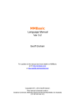
6. Module: 10-bit ADC: Sampling Rate
The maximum sampling rate for the 10-bit
Analog-to-Digital Conversion module is 750 ksps.
This rate is only achievable when one A/D pin is
being used. Configuring the ADC module to use
multiple sample-and-hold circuits (see device data
sheet), will not improve the conversion speed of
the module.
Table 1 shows the maximum ADC conversion
rates possible using the 10-bit ADC module and
the corresponding module configuration and
operating conditions.
TABLE 1:
10-BIT ADC RATE PARAMETERS
dsPIC30F 10-bit ADC Conversion Rates
A/D Speed
Up to
750 ksps
TAD
Sampling
Minimum Time Min
95.24 ns
2 TAD
RS Max
VDD
Temperature
500Ω
4.5V to 5.5V
-40°C to +85°C
A/D Channels Configuration
VREF- VREF+
CHX
ANx
S/H
Up to
500 ksps
153.85 ns
1 TAD
5.0 kΩ
4.5V to 5.5V
ADC
-40°C to +125°C
VREF- VREF+
or
or
AVSS AVDD
CHX
ANx
S/H
ADC
ANx or VREF-
Up to
300 ksps
256.41 ns
1 TAD
5.0 kΩ
3.0V to 5.5V
-40°C to +125°C
VREF- VREF+
or
or
AVSS AVDD
CHX
ANx
S/H
ADC
ANx or VREF-
Work around
None.
© 2008 Microchip Technology Inc.
DS80258G-page 5
dsPIC30F6010A/6015
7. Module: QEI Interrupt Generation
Work around
The Quadrature Encoder Interface (QEI) module
does not generate an interrupt when MAXCNT is
set to 0xFFFF and the following events occur:
To prevent this condition from occurring, set
MAXCNT to 0x7FFF, which will cause an interrupt
to be generated by the QEI module.
1. POSCNT underflows from 0x0000 to 0xFFFF.
2. POSCNT stops.
3. POSCNT overflows from 0xFFFF to 0x0000.
In addition, a global variable could be used to keep
track of bit 15, so that when an overflow or
underflow condition is present on POSCNT, the
variable will toggle bit 15. Example 1 shows the
code required for this global variable.
This sequence of events occurs when the motor is
running in one direction, which causes POSCNT to
underflow to 0xFFFF. Once this happens, the
motor stops and starts to run in the opposite
direction, which generates an overflow from
0xFFFF to 0x0000. The QEI module does not
generate an interrupt when this condition occurs.
EXAMPLE 1:
unsigned int POSCNT_b15 = 0;
unsigned int Motor_Position = 0;
int main(void)
{
// ... User's code
MAXCNT = 0x7FFF;
// Instead of 0xFFFF
Motor_Position = POSCNT_b15 + POSCNT;
// ... User's code
}
void __attribute__((__interrupt__)) _QEIInterrupt(void)
{
IFSxbits.QEIIF = 0;
// Clear QEI interrupt flag
// x=2 for dsPIC30F
// x=3 for dsPIC33F
POSCNT_b15 ^= 0x8000; // Overflow or Underflow
}
DS80258G-page 6
© 2008 Microchip Technology Inc.
dsPIC30F6010A/6015
8. Module: Sleep Mode
Execution of the Sleep instruction (PWRSAV #0)
may cause incorrect program operation after the
device wakes up from Sleep. The current
consumption during Sleep may also increase
beyond the specifications listed in the device data
sheet.
Work arounds
To avoid this issue, any of the following three work
arounds can be implemented, depending on the
application requirements.
Work around 1:
Ensure that the PWRSAV #0 instruction is located
at the end of the last row of program Flash memory
available on the target device and fill the
remainder of the row with NOP instructions.
This can be accomplished by replacing all
occurrences of the PWRSAV #0 instruction with a
function call to a suitably aligned subroutine. The
address( ) attribute provided by the MPLAB
ASM30 assembler can be utilized to correctly align
the instructions in the subroutine. For an
application written in C, the function call would be
GotoSleep( ), while for an assembly language
application, the function call would be
CALL _GotoSleep.
The address error trap service routine software
can then replace the invalid return address saved
on the stack with the address of the instruction
immediately following the _GotoSleep or
GotoSleep( ) function call. This ensures that
the device continues executing the correct code
sequence after waking up from Sleep mode.
Example 2 demonstrates the work around
described above, as it would apply to a
dsPIC30F6010A device.
EXAMPLE 2:
; ---------------------------------------------------------------------------------------------.global __reset
.global _main
.global _GotoSleep
.global __AddressError
.global __INT1Interrupt
; ---------------------------------------------------------------------------------------------.section *, code
_main:
BSET
INTCON2, #INT1EP ; Set up INT pins to detect falling edge
BCLR
IFS1, #INT1IF
; Clear interrupt pin interrupt flag bits
BSET
IEC1, #INT1IE
; Enable ISR processing for INT pins
CALL
_GotoSleep
; Call function to enter SLEEP mode
_continue:
BRA _continue
; ---------------------------------------------------------------------------------------------; Address Error Trap
__AddressError:
BCLR
INTCON1, #ADDRERR
; Set program memory return address to _continue
POP.D
W0
MOV.B
#tblpage (_continue), W1
MOV
#tbloffset (_continue), W0
PUSH.D W0
RETFIE
; ---------------------------------------------------------------------------------------------__INT1Interrupt:
BCLR
IFS1, #INT1IF
; Ensure flag is reset
RETFIE
; Return from Interrupt Service Routine
; ---------------------------------------------------------------------------------------------.section *, code, address (0x17FC0)
_GotoSleep:
; fill remainder of the last row with NOP instructions
.rept 31
NOP
.endr
; Place SLEEP instruction in the last word of program memory
PWRSAV #0
© 2008 Microchip Technology Inc.
DS80258G-page 7
dsPIC30F6010A/6015
Work around 2:
Work around 3:
Instead of executing a PWRSAV #0 instruction to
put the device into Sleep mode, perform a clock
switch to the 512 kHz Low-Power RC (LPRC)
Oscillator with a 64:1 postscaler mode. This
enables the device to operate at 0.002 MIPS,
thereby significantly reducing the current
consumption of the device. Similarly, instead of
using an interrupt to wake-up the device from
Sleep mode, perform another clock switch back to
the original oscillator source to resume normal
operation. Depending on the device, refer to
Section 7. “Oscillator” (DS70054) or Section
29. “Oscillator” (DS70268) in the “dsPIC30F
Family Reference Manual” (DS70046) for more
details on performing a clock switch operation.
Instead of executing a PWRSAV #0 instruction to
put the device into Sleep mode, perform a clock
switch to the 32 kHz Low-Power (LP) Oscillator
with a 64:1 postscaler mode. This enables the
device to operate at 0.000125 MIPS, thereby
significantly reducing the current consumption of
the device. Similarly, instead of using an interrupt
to wake-up the device from Sleep mode, perform
another clock switch back to the original oscillator
source to resume normal operation. Depending on
the device, refer to Section 7. “Oscillator”
(DS70054) or Section 29. “Oscillator”
(DS70268) in the “dsPIC30F Family Reference
Manual” (DS70046) for more details on performing
a clock switch operation.
Note:
The above work around is recommended
for users for whom application hardware
changes are not possible.
DS80258G-page 8
Note:
The above work around is recommended
for users for whom application hardware
changes are possible, and also for users
whose application hardware already
includes a 32 kHz LP Oscillator crystal.
© 2008 Microchip Technology Inc.
dsPIC30F6010A/6015
9. Module: I2C
Work around 2:
When the I2C module is configured as a slave,
either in single-master or multi-master mode, the
I2C receiver buffer is filled whether a valid slave
address is detected or not. Therefore, an I2C
receiver overflow condition occurs and this condition is indicated by the I2COV flag in the I2CSTAT
register.
Use this work around for applications in which the
I2C receiver interrupt is required. Assuming that
the RBF and the I2COV flags in the I2CSTAT
register are set due to previous data transfers in
the I2C bus (i.e., between master and other
slaves); the following procedure can be used to
receive valid data bytes:
This overflow condition inhibits the ability to set the
I2C receive interrupt flag (SI2CF) when the last
valid data byte is received. Therefore, the I2C
slave Interrupt Service Routine (ISR) is not called
and the I2C receiver buffer is not read prior
receiving the next data byte.
1. When a valid slave address byte is detected,
SI2CF bit is set and the I2C slave interrupt
service routine is called; however, the RBF and
I2COV bits are already set due to data
transfers between other I2C nodes.
2. Check the status of the D_A flag and the
I2COV flag in the I2CSTAT register when
executing the I2C slave service routine.
3. If the D_A flag is cleared and the I2COV flag
are set, an invalid data byte was received but a
valid address byte was received. The overflow
condition occurred because the I2C receive
buffer was overflowing with previous I2C data
transfers between other I2C nodes. This
condition only occurs after a valid slave
address was detected.
4. Clear the I2COV flag and perform a dummy
read of the I2C receiver buffer, I2CRCV, to
clear the RBF bit and recover the valid address
byte. This action will also avoid the loss of the
next data byte due to an overflow condition.
5. Verify that the recovered address byte
matches the current slave address byte. If they
match, the next data to be received is a valid
data byte.
6. If the D_A flag and the I2COV flag are both set,
a valid data byte was received and a previous
valid data byte was lost. It will be necessary to
code for handling this overflow condition.
Work arounds
To avoid this issue, either of the following two work
arounds can be implemented, depending on the
application requirements.
Work around 1:
For applications in which the I2C receiver interrupt
is not required, the following procedure can be
used to receive valid data bytes:
1. Wait until the RBF flag is set.
2. Poll the I2C receiver interrupt SI2CIF flag.
3. If SI2CF is not set in the corresponding
Interrupt Flag Status (IFSx) register, a valid
address or data byte has not been received for
the current slave. Execute a dummy read of
the I2C receiver buffer, I2CRCV; this will clear
the RBF flag. Go back to step 1 until SI2CF is
set and then continue to Step 4.
4. If the SI2CF is set in the corresponding
Interrupt Flag Status (IFSx) register, valid data
has been received. Check the D_A flag to
verify that an address or a data byte has been
received.
5. Read the I2CRCV buffer to recover valid data
bytes. This will also clear the RBF flag.
6. Clear the I2C receiver interrupt flag SI2CF.
7. Go back to step 1 to continue receiving
incoming data bytes.
10. Module: Motor Control PWM – PWM
Counter Register
If the PTDIR bit is set (when PTMR is counting
down), and the CPU execution is halted (after a
breakpoint is reached), PTMR will start counting
up as if PTDIR was zero.
Work around
None.
© 2008 Microchip Technology Inc.
DS80258G-page 9
dsPIC30F6010A/6015
11. Module: I/O Port – Port Pin Multiplexed
with IC1
If the user application enables the auto-baud
feature in the UART module, the I/O pin
multiplexed with the IC1 (Input Capture) pin cannot
be used as a digital input.
Work around
None.
15. Module: PSV Operations
An address error trap occurs in certain addressing
modes when accessing the first four bytes of an
PSV page. This only occurs when using the
following addressing modes:
• MOV.D
• Register Indirect Addressing (word or byte
mode) with pre/post-decrement
Work around
12. Module: I2C
If there are two I2C devices on the bus, one of
them is acting as the Master receiver and the other
as the Slave transmitter. If both devices are configured for 10-bit addressing mode, and have the
same value in the A10 and A9 bits of their
addresses, then when the Slave select address is
sent from the Master, both the Master and Slave
acknowledge it. When the Master sends out the
read operation, both the Master and the Slave
enter into Read mode and both of them transmit
the data. The resultant data will be the ANDing of
the two transmissions.
Work around
In all I2C devices, the addresses as well as bits
A10 and A9 should be different.
13. Module: Timer
Do not perform PSV accesses to any of the first
four bytes using the above addressing modes. For
applications using the C language, MPLAB C30
version 3.11 or higher, provides the following
command-line switch that implements a work
around for the erratum.
-merrata=psv_trap
Refer to the readme.txt file in the MPLAB C30
v3.11 tool suite for further details.
16. Module: I2C
In 10-bit Addressing mode, some address
matches don't set the RBF flag or load the receive
register I2CxRCV, if the lower address byte
matches the reserved addresses. In particular,
these include all addresses with the form
XX0000XXXX and XX1111XXXX, with the
following exceptions:
When the timer is being operated in Asynchronous
mode using the secondary oscillator (32.768 kHz)
and the device is put into Sleep mode, a clock
switch to any other oscillator mode before putting
the device to Sleep prevents the timer from waking
the device from Sleep.
•
•
•
•
Work around
Ensure that the lower address byte in 10-bit
Addressing mode does not match any 7-bit
reserved addresses.
Do not clock switch to any other oscillator mode if
the timer is being used in Asynchronous mode
using the secondary oscillator (32.768 kHz).
14. Module: PLL Lock Status Bit
The PLL LOCK Status bit (OSCCON<5>) can
occasionally get cleared and generate an
oscillator failure trap even when the PLL is still
locked and functioning correctly.
Work around
The user application must include an oscillator
failure trap service routine. In the trap service
routine, first inspect the status of the Clock Failure
Status bit (OSCCON<3>). If this bit is clear, return
from the trap service routine immediately and
continue program execution.
DS80258G-page 10
001111000X
011111001X
101111010X
111111011X
Work around
17. Module: I2C
When the I2C module is configured as a 10-bit
slave with and address of 0x102, the I2CxRCV
register content for the lower address byte is 0x01
rather than 0x02; however, the module
acknowledges both address bytes.
Work around
None.
© 2008 Microchip Technology Inc.
dsPIC30F6010A/6015
18. Module: I2C
When the I2C module is enabled by setting the
I2CEN bit in the I2CCON register, the dsPIC DSC
device generates a glitch on the SDA and SCL
pins. This glitch falsely indicates “Communication
Start” to all devices on the I2C bus, and can cause
a bus collision in a multi-master configuration.
Additionally, when the I2CEN bit is set, the S and
P bits of the I2C module are set to values ‘1’ and
‘0’, respectively, which indicate a “Communication
Start” condition.
Work arounds
To avoid this issue, either of the following two work
arounds can be implemented, depending on the
application requirements.
Work around 1:
In a single-master environment, add a delay
between enabling the I2C module and the first data
transmission. The delay should be equal to or
greater than the time it takes to transmit two data
bits.
In the multi-master configuration, in addition to the
delay, all other I2C masters should be synchronized and wait for the I2C module to be initialized
before initiating any kind of communication.
Work around 2:
In dsPIC DSC devices in which the I2C module is
multiplexed with other modules that have
precedence in the use of the pin, it is possible to
avoid this glitch by enabling the higher priority
module before enabling the I2C module.
Use the following procedure to implement this
work around:
1. Enable the higher priority peripheral module
that is multiplexed on the same pins as the I2C
module.
2. Set up and enable the I2C module.
3. Disable the higher priority peripheral module
that was enabled in step 1.
Note:
Work around 2 works only for devices that
share the SDA and SCL pins with another
peripheral that has a higher precedence
over the port latch, such as the UART. The
priority is shown in the pin diagram located
in the data sheet. For example, if the SDA
and SCL pins are shared with the UART
and SPI pins, and the UART has higher
precedence on the port latch pin.
© 2008 Microchip Technology Inc.
DS80258G-page 11
dsPIC30F6010A/6015
APPENDIX A:
REVISION HISTORY
Revision A (01/2006)
Original version of the document.
Revision B (9/2006)
Added silicon issues 1 and 6.
Revision C (3/2007)
Added silicon issue 7.
Revision D (9/2007)
Added silicon issue 8 (QEI Interrupt Generation) and 9
(Sleep Mode).
Revision E (12/2007)
Added silicon issues 10 and 11 (I2C), 12 (Motor Control
PWM – PWM Counter Register), and 13 (I/O Port –
Port Pin Multiplexed with IC1).
Revision F (5/2008)
Added silicon issues 13 and 14 (I2C), and 15 (Timer).
Removed silicon issue 4 (Using OSC2/RC15 pin for
Clock Output).
Revision G (9/2008)
Updated silicon revision to A2/A3. Replaced issues 9
and 13 (I2C) with issue 18 (I2C). Added silicon issues
14 (PLL Lock Status Bit), 15 (PSV Operations) and
16-18 (I2C).
DS80258G-page 12
© 2008 Microchip Technology Inc.
Note the following details of the code protection feature on Microchip devices:
•
Microchip products meet the specification contained in their particular Microchip Data Sheet.
•
Microchip believes that its family of products is one of the most secure families of its kind on the market today, when used in the
intended manner and under normal conditions.
•
There are dishonest and possibly illegal methods used to breach the code protection feature. All of these methods, to our
knowledge, require using the Microchip products in a manner outside the operating specifications contained in Microchip’s Data
Sheets. Most likely, the person doing so is engaged in theft of intellectual property.
•
Microchip is willing to work with the customer who is concerned about the integrity of their code.
•
Neither Microchip nor any other semiconductor manufacturer can guarantee the security of their code. Code protection does not
mean that we are guaranteeing the product as “unbreakable.”
Code protection is constantly evolving. We at Microchip are committed to continuously improving the code protection features of our
products. Attempts to break Microchip’s code protection feature may be a violation of the Digital Millennium Copyright Act. If such acts
allow unauthorized access to your software or other copyrighted work, you may have a right to sue for relief under that Act.
Information contained in this publication regarding device
applications and the like is provided only for your convenience
and may be superseded by updates. It is your responsibility to
ensure that your application meets with your specifications.
MICROCHIP MAKES NO REPRESENTATIONS OR
WARRANTIES OF ANY KIND WHETHER EXPRESS OR
IMPLIED, WRITTEN OR ORAL, STATUTORY OR
OTHERWISE, RELATED TO THE INFORMATION,
INCLUDING BUT NOT LIMITED TO ITS CONDITION,
QUALITY, PERFORMANCE, MERCHANTABILITY OR
FITNESS FOR PURPOSE. Microchip disclaims all liability
arising from this information and its use. Use of Microchip
devices in life support and/or safety applications is entirely at
the buyer’s risk, and the buyer agrees to defend, indemnify and
hold harmless Microchip from any and all damages, claims,
suits, or expenses resulting from such use. No licenses are
conveyed, implicitly or otherwise, under any Microchip
intellectual property rights.
Trademarks
The Microchip name and logo, the Microchip logo, Accuron,
dsPIC, KEELOQ, KEELOQ logo, MPLAB, PIC, PICmicro,
PICSTART, rfPIC, SmartShunt and UNI/O are registered
trademarks of Microchip Technology Incorporated in the
U.S.A. and other countries.
FilterLab, Linear Active Thermistor, MXDEV, MXLAB,
SEEVAL, SmartSensor and The Embedded Control Solutions
Company are registered trademarks of Microchip Technology
Incorporated in the U.S.A.
Analog-for-the-Digital Age, Application Maestro, CodeGuard,
dsPICDEM, dsPICDEM.net, dsPICworks, dsSPEAK, ECAN,
ECONOMONITOR, FanSense, In-Circuit Serial
Programming, ICSP, ICEPIC, Mindi, MiWi, MPASM, MPLAB
Certified logo, MPLIB, MPLINK, mTouch, PICkit, PICDEM,
PICDEM.net, PICtail, PIC32 logo, PowerCal, PowerInfo,
PowerMate, PowerTool, REAL ICE, rfLAB, Select Mode, Total
Endurance, WiperLock and ZENA are trademarks of
Microchip Technology Incorporated in the U.S.A. and other
countries.
SQTP is a service mark of Microchip Technology Incorporated
in the U.S.A.
All other trademarks mentioned herein are property of their
respective companies.
© 2008, Microchip Technology Incorporated, Printed in the
U.S.A., All Rights Reserved.
Printed on recycled paper.
Microchip received ISO/TS-16949:2002 certification for its worldwide
headquarters, design and wafer fabrication facilities in Chandler and
Tempe, Arizona; Gresham, Oregon and design centers in California
and India. The Company’s quality system processes and procedures
are for its PIC® MCUs and dsPIC® DSCs, KEELOQ® code hopping
devices, Serial EEPROMs, microperipherals, nonvolatile memory and
analog products. In addition, Microchip’s quality system for the design
and manufacture of development systems is ISO 9001:2000 certified.
© 2008 Microchip Technology Inc.
DS80258G-page 13
Worldwide Sales and Service
AMERICAS
ASIA/PACIFIC
ASIA/PACIFIC
EUROPE
Corporate Office
2355 West Chandler Blvd.
Chandler, AZ 85224-6199
Tel: 480-792-7200
Fax: 480-792-7277
Technical Support:
http://support.microchip.com
Web Address:
www.microchip.com
Asia Pacific Office
Suites 3707-14, 37th Floor
Tower 6, The Gateway
Harbour City, Kowloon
Hong Kong
Tel: 852-2401-1200
Fax: 852-2401-3431
India - Bangalore
Tel: 91-80-4182-8400
Fax: 91-80-4182-8422
India - New Delhi
Tel: 91-11-4160-8631
Fax: 91-11-4160-8632
Austria - Wels
Tel: 43-7242-2244-39
Fax: 43-7242-2244-393
Denmark - Copenhagen
Tel: 45-4450-2828
Fax: 45-4485-2829
India - Pune
Tel: 91-20-2566-1512
Fax: 91-20-2566-1513
France - Paris
Tel: 33-1-69-53-63-20
Fax: 33-1-69-30-90-79
Japan - Yokohama
Tel: 81-45-471- 6166
Fax: 81-45-471-6122
Germany - Munich
Tel: 49-89-627-144-0
Fax: 49-89-627-144-44
Atlanta
Duluth, GA
Tel: 678-957-9614
Fax: 678-957-1455
Boston
Westborough, MA
Tel: 774-760-0087
Fax: 774-760-0088
Chicago
Itasca, IL
Tel: 630-285-0071
Fax: 630-285-0075
Dallas
Addison, TX
Tel: 972-818-7423
Fax: 972-818-2924
Detroit
Farmington Hills, MI
Tel: 248-538-2250
Fax: 248-538-2260
Kokomo
Kokomo, IN
Tel: 765-864-8360
Fax: 765-864-8387
Los Angeles
Mission Viejo, CA
Tel: 949-462-9523
Fax: 949-462-9608
Santa Clara
Santa Clara, CA
Tel: 408-961-6444
Fax: 408-961-6445
Toronto
Mississauga, Ontario,
Canada
Tel: 905-673-0699
Fax: 905-673-6509
Australia - Sydney
Tel: 61-2-9868-6733
Fax: 61-2-9868-6755
China - Beijing
Tel: 86-10-8528-2100
Fax: 86-10-8528-2104
China - Chengdu
Tel: 86-28-8665-5511
Fax: 86-28-8665-7889
Korea - Daegu
Tel: 82-53-744-4301
Fax: 82-53-744-4302
China - Hong Kong SAR
Tel: 852-2401-1200
Fax: 852-2401-3431
Korea - Seoul
Tel: 82-2-554-7200
Fax: 82-2-558-5932 or
82-2-558-5934
China - Nanjing
Tel: 86-25-8473-2460
Fax: 86-25-8473-2470
Malaysia - Kuala Lumpur
Tel: 60-3-6201-9857
Fax: 60-3-6201-9859
China - Qingdao
Tel: 86-532-8502-7355
Fax: 86-532-8502-7205
Malaysia - Penang
Tel: 60-4-227-8870
Fax: 60-4-227-4068
China - Shanghai
Tel: 86-21-5407-5533
Fax: 86-21-5407-5066
Philippines - Manila
Tel: 63-2-634-9065
Fax: 63-2-634-9069
China - Shenyang
Tel: 86-24-2334-2829
Fax: 86-24-2334-2393
Singapore
Tel: 65-6334-8870
Fax: 65-6334-8850
China - Shenzhen
Tel: 86-755-8203-2660
Fax: 86-755-8203-1760
Taiwan - Hsin Chu
Tel: 886-3-572-9526
Fax: 886-3-572-6459
China - Wuhan
Tel: 86-27-5980-5300
Fax: 86-27-5980-5118
Taiwan - Kaohsiung
Tel: 886-7-536-4818
Fax: 886-7-536-4803
China - Xiamen
Tel: 86-592-2388138
Fax: 86-592-2388130
Taiwan - Taipei
Tel: 886-2-2500-6610
Fax: 886-2-2508-0102
China - Xian
Tel: 86-29-8833-7252
Fax: 86-29-8833-7256
Thailand - Bangkok
Tel: 66-2-694-1351
Fax: 66-2-694-1350
Italy - Milan
Tel: 39-0331-742611
Fax: 39-0331-466781
Netherlands - Drunen
Tel: 31-416-690399
Fax: 31-416-690340
Spain - Madrid
Tel: 34-91-708-08-90
Fax: 34-91-708-08-91
UK - Wokingham
Tel: 44-118-921-5869
Fax: 44-118-921-5820
China - Zhuhai
Tel: 86-756-3210040
Fax: 86-756-3210049
01/02/08
DS80258G-page 14
© 2008 Microchip Technology Inc.