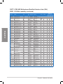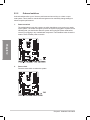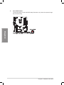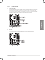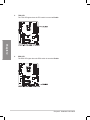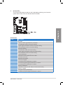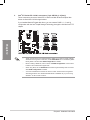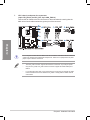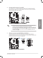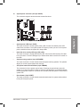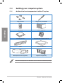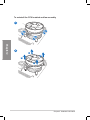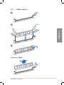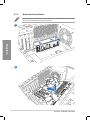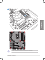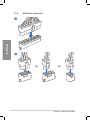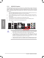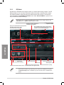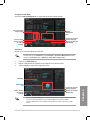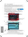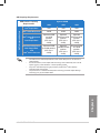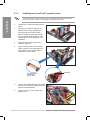
1
Motherboard
P8Z77-V
DELUXE
E7163
Second Edition
February 2012
Copyright © 2012 ASUSTeK COMPUTER INC. All Rights Reserved.
No part of this manual, including the products and software described in it, may be reproduced,
transmitted, transcribed, stored in a retrieval system, or translated into any language in any form or by any
means, except documentation kept by the purchaser for backup purposes, without the express written
permission of ASUSTeK COMPUTER INC. (“ASUS”).
Product warranty or service will not be extended if: (1) the product is repaired, modified or altered, unless
such repair, modification of alteration is authorized in writing by ASUS; or (2) the serial number of the
product is defaced or missing.
ASUS PROVIDES THIS MANUAL “AS IS” WITHOUT WARRANTY OF ANY KIND, EITHER EXPRESS
OR IMPLIED, INCLUDING BUT NOT LIMITED TO THE IMPLIED WARRANTIES OR CONDITIONS OF
MERCHANTABILITY OR FITNESS FOR A PARTICULAR PURPOSE. IN NO EVENT SHALL ASUS, ITS
DIRECTORS, OFFICERS, EMPLOYEES OR AGENTS BE LIABLE FOR ANY INDIRECT, SPECIAL,
INCIDENTAL, OR CONSEQUENTIAL DAMAGES (INCLUDING DAMAGES FOR LOSS OF PROFITS,
LOSS OF BUSINESS, LOSS OF USE OR DATA, INTERRUPTION OF BUSINESS AND THE LIKE),
EVEN IF ASUS HAS BEEN ADVISED OF THE POSSIBILITY OF SUCH DAMAGES ARISING FROM ANY
DEFECT OR ERROR IN THIS MANUAL OR PRODUCT.
SPECIFICATIONS AND INFORMATION CONTAINED IN THIS MANUAL ARE FURNISHED FOR
INFORMATIONAL USE ONLY, AND ARE SUBJECT TO CHANGE AT ANY TIME WITHOUT NOTICE,
AND SHOULD NOT BE CONSTRUED AS A COMMITMENT BY ASUS. ASUS ASSUMES NO
RESPONSIBILITY OR LIABILITY FOR ANY ERRORS OR INACCURACIES THAT MAY APPEAR IN THIS
MANUAL, INCLUDING THE PRODUCTS AND SOFTWARE DESCRIBED IN IT.
Products and corporate names appearing in this manual may or may not be registered trademarks or
copyrights of their respective companies, and are used only for identification or explanation and to the
owners’ benefit, without intent to infringe.
Offer to Provide Source Code of Certain Software
This product may contain copyrighted software that is licensed under the General Public License (“GPL”)
and under the Lesser General Public License Version (“LGPL”). The GPL and LGPL licensed code in this
product is distributed without any warranty. Copies of these licenses are included in this product.
You may obtain the complete corresponding source code (as defined in the GPL) for the GPL Software,
and/or the complete corresponding source code of the LGPL Software (with the complete machinereadable “work that uses the Library”) for a period of three years after our last shipment of the product
including the GPL Software and/or LGPL Software, which will be no earlier than December 1, 2011, either
(1) for free by downloading it from http://support.asus.com/download;
or
(2) for the cost of reproduction and shipment, which is dependent on the preferred carrier and the location
where you want to have it shipped to, by sending a request to:
ASUSTeK Computer Inc.
Legal Compliance Dept.
15 Li Te Rd.,
Beitou, Taipei 112
Taiwan
In your request please provide the name, model number and version, as stated in the About Box of the
product for which you wish to obtain the corresponding source code and your contact details so that we
can coordinate the terms and cost of shipment with you.
The source code will be distributed WITHOUT ANY WARRANTY and licensed under the same license as
the corresponding binary/object code.
This offer is valid to anyone in receipt of this information.
ASUSTeK is eager to duly provide complete source code as required under various Free Open Source
Software licenses. If however you encounter any problems in obtaining the full corresponding source code
we would be much obliged if you give us a notification to the email address [email protected], stating the
product and describing the problem (please do NOT send large attachments such as source code archives
etc to this email address).
ii
Contents
Safety information...................................................................................................... vii
About this guide........................................................................................................ viii
P8Z77-V DELUXE specifications summary............................................................... x
Chapter 1:
Product introduction
1.1
Welcome!..................................................................................................... 1-1
1.2
Package contents....................................................................................... 1-1
1.3
Special features.......................................................................................... 1-2
1.3.1
Product highlights........................................................................ 1-2
1.3.2
Dual Intelligent Processors 3.1 with New DIGI+ Power Control.. 1-4
1.3.3
ASUS Exclusive Features............................................................ 1-5
1.3.4
ASUS Quiet Thermal Solution...................................................... 1-7
1.3.5
ASUS EZ DIY............................................................................... 1-7
1.3.6
Other special features.................................................................. 1-8
Chapter 2:
2.1
2.2
2.3
Hardware information
Before you proceed.................................................................................... 2-1
Motherboard overview................................................................................ 2-2
2.2.1
Motherboard layout...................................................................... 2-2
2.2.2
Central Processing Unit (CPU).................................................... 2-4
2.2.3
System memory........................................................................... 2-5
2.2.4
Expansion slots.......................................................................... 2-14
2.2.5
Onboard switches...................................................................... 2-16
2.2.6
Onboard LEDs........................................................................... 2-21
2.2.7
Internal connectors.................................................................... 2-27
Building your computer system.............................................................. 2-36
2.3.1
Additional tools and components to build a PC system............. 2-36
2.3.2
CPU installation......................................................................... 2-37
2.3.3
CPU heatsink and fan assembly installation.............................. 2-39
2.3.4
DIMM installation....................................................................... 2-41
2.3.5
Motherboard installation............................................................. 2-42
2.3.6
ATX Power connection............................................................... 2-44
2.3.7
SATA device connection............................................................. 2-45
2.3.8
Front I/O Connector................................................................... 2-46
2.3.9
Expansion Card installation....................................................... 2-47
2.3.10
Wireless and Bluetooth Module Installation............................... 2-48
2.3.11
USB BIOS Flashback................................................................. 2-50
2.3.12
Rear panel connection............................................................... 2-51
2.3.13
Audio I/O connections................................................................ 2-53
iii
Contents
2.4
Starting up for the first time..................................................................... 2-55
2.5 Turning off the computer.......................................................................... 2-55
Chapter 3:
Knowing BIOS............................................................................................. 3-1
3.2
BIOS setup program................................................................................... 3-1
3.2.1
EZ Mode...................................................................................... 3-2
3.2.2
Advanced Mode........................................................................... 3-3
3.3
Main menu................................................................................................... 3-5
3.4
Ai Tweaker menu......................................................................................... 3-7
3.5
Advanced menu........................................................................................ 3-18
3.5.1
CPU Configuration..................................................................... 3-19
3.5.3
SATA Configuration.................................................................... 3-22
3.5.2
3.5.4
3.5.5
3.5.6
PCH Configuration..................................................................... 3-21
System Agent Configuration...................................................... 3-23
USB Configuration..................................................................... 3-25
Onboard Devices Configuration................................................. 3-26
3.5.7
APM........................................................................................... 3-29
3.5.8
Network Stack............................................................................ 3-30
3.6
Monitor menu............................................................................................ 3-31
3.7
Boot menu................................................................................................. 3-35
3.8
3.9
3.10
Tools menu................................................................................................ 3-37
3.8.1
ASUS EZ Flash 2 Utility............................................................. 3-37
3.8.2.
ASUS O.C. Profile...................................................................... 3-37
3.8.3.
ASUS SPD Information.............................................................. 3-38
3.8.4.
ASUS Drive Xpert...................................................................... 3-39
Exit menu................................................................................................... 3-40
Updating BIOS........................................................................................... 3-41
3.10.1
ASUS Update utility................................................................... 3-41
3.10.2
ASUS EZ Flash 2 utility.............................................................. 3-44
3.10.3
ASUS CrashFree BIOS 3 utility................................................. 3-45
3.10.4
ASUS BIOS Updater.................................................................. 3-46
Chapter 4:
Software support
4.1
Installing an operating system.................................................................. 4-1
4.2
Support DVD information........................................................................... 4-1
4.3
iv
BIOS setup
3.1
4.2.1
Running the support DVD............................................................ 4-1
4.2.2
Obtaining the software manuals.................................................. 4-2
Software information.................................................................................. 4-3
Contents
4.4
4.5
4.3.1
AI Suite II..................................................................................... 4-3
4.3.2
TurboV EVO................................................................................. 4-4
4.3.3
DIGI+ Power Control.................................................................... 4-8
4.3.4
EPU............................................................................................ 4-12
4.3.5
USB 3.0 Boost........................................................................... 4-13
4.3.6
USB BIOS Flashback Wizard.................................................... 4-14
4.3.7
ASUS SSD Caching................................................................... 4-16
4.3.8
Probe II...................................................................................... 4-17
4.3.9
Sensor Recorder........................................................................ 4-18
4.3.10
ASUS Update............................................................................. 4-19
4.3.11
MyLogo2.................................................................................... 4-20
4.3.12
Audio configurations.................................................................. 4-22
4.4.1
RAID definitions......................................................................... 4-23
4.4.2
Installing Serial ATA hard disks.................................................. 4-24
4.4.3
Setting the RAID item in BIOS................................................... 4-24
4.4.4
Intel® Rapid Storage Technology Option ROM utility................. 4-24
4.4.5
Marvell RAID utility..................................................................... 4-28
4.4.6
Introduction to Intel® 2012 Desktop responsiveness
technologies............................................................................... 4-32
RAID configurations................................................................................. 4-23
Creating a RAID driver disk..................................................................... 4-44
4.5.1
Creating a RAID driver disk without entering the OS................. 4-44
4.5.2
Creating a RAID driver disk in Windows®.................................. 4-44
4.5.3
Installing the RAID driver during Windows® OS installation....... 4-45
4.5.4
Using a USB floppy disk drive.................................................... 4-46
Chapter 5:
5.1
5.2
Multiple GPU technology support
ATI® CrossFireX™ technology................................................................... 5-1
5.1.1
Requirements............................................................................... 5-1
5.1.2
Before you begin.......................................................................... 5-1
5.1.3
Installing two CrossFireX™ graphics cards................................. 5-2
5.1.4
Installing the device drivers.......................................................... 5-3
5.1.5
Enabling the ATI® CrossFireX™ technology................................ 5-3
NVIDIA® SLI™ technology.......................................................................... 5-4
5.2.1
Requirements............................................................................... 5-4
5.2.2
Installing two SLI-ready graphics cards....................................... 5-4
5.2.3
Installing the device drivers.......................................................... 5-5
5.2.4
Enabling the NVIDIA® SLI™ technology...................................... 5-5
5.3
LucidLogix Virtu MVP................................................................................. 5-8
5.3.1
Installing LucidLogix Virtu MVP.................................................... 5-8
5.3.2
Setting up your display................................................................. 5-9
5.3.3
Configuring LucidLogix Virtu MVP............................................. 5-10
Appendices
Notices..................................................................................................................... A-1
RF Equipment Notices............................................................................................. A-3
vi
Safety information
Electrical safety
•
To prevent electrical shock hazard, disconnect the power cable from the electrical outlet
before relocating the system.
•
When adding or removing devices to or from the system, ensure that the power cables
for the devices are unplugged before the signal cables are connected. If possible,
disconnect all power cables from the existing system before you add a device.
•
Before connecting or removing signal cables from the motherboard, ensure that all
power cables are unplugged.
•
Seek professional assistance before using an adapter or extension cord. These devices
could interrupt the grounding circuit.
•
Ensure that your power supply is set to the correct voltage in your area. If you are not
sure about the voltage of the electrical outlet you are using, contact your local power
company.
•
If the power supply is broken, do not try to fix it by yourself. Contact a qualified service
technician or your retailer.
Operation safety
•
Before installing the motherboard and adding devices on it, carefully read all the manuals
that came with the package.
•
Before using the product, ensure all cables are correctly connected and the power
cables are not damaged. If you detect any damage, contact your dealer immediately.
•
To avoid short circuits, keep paper clips, screws, and staples away from connectors,
slots, sockets and circuitry.
•
Avoid dust, humidity, and temperature extremes. Do not place the product in any area
where it may become wet.
•
Place the product on a stable surface.
•
If you encounter technical problems with the product, contact a qualified service
technician or your retailer.
vii
About this guide
This user guide contains the information you need when installing and configuring the motherboard.
How this guide is organized
This guide contains the following parts:
•
Chapter 1: Product introduction
This chapter describes the features of the motherboard and the new technology it
supports.
•
Chapter 2: Hardware information
This chapter lists the hardware setup procedures that you have to perform when
installing system components. It includes description of the switches, jumpers, and
connectors on the motherboard.
•
Chapter 3: BIOS setup
This chapter tells how to change system settings through the BIOS Setup menus.
Detailed descriptions of the BIOS parameters are also provided.
•
Chapter 4: Software support
This chapter describes the contents of the support DVD that comes with the
motherboard package and the software.
•
Chapter 5: Multiple GPU technology support
This chapter describes how to install and configure multiple ATI® CrossFireX™ and
NVIDIA® SLI™ graphics cards.
Where to find more information
Refer to the following sources for additional information and for product and software updates.
1.
ASUS websites
The ASUS website provides updated information on ASUS hardware and software
products. Refer to the ASUS contact information.
2.
Optional documentation
Your product package may include optional documentation, such as warranty flyers,
that may have been added by your dealer. These documents are not part of the
standard package.
viii
Conventions used in this guide
To ensure that you perform certain tasks properly, take note of the following symbols used
throughout this manual.
DANGER/WARNING: Information to prevent injury to yourself when trying to
complete a task.
CAUTION: Information to prevent damage to the components when trying to
complete a task.
IMPORTANT: Instructions that you MUST follow to complete a task.
NOTE: Tips and additional information to help you complete a task.
Typography
Bold text
Indicates a menu or an item to select.
Italics
Used to emphasize a word or a phrase.
<Key>
Keys enclosed in the less-than and greater-than sign means ��
��������������������������������������
that you must press the enclosed key.
Example: <Enter> means that you must press the Enter or ��
�����������
Return key.
<Key1> + <Key2> + <Key3> If you must press two or more keys simultaneously, the key names are linked with a plus sign (+).
Example: <Ctrl> + <Alt> + <Del>
ix
P8Z77-V DELUXE specifications summary
CPU
LGA1155 socket for Intel® 3rd/2nd Generation Core™ i7 / ������
Core™
i5 / Core™ i3 / Pentium® / Celeron® Processors
Supports 22/32nm CPU
Supports Intel® Turbo Boost Technology 2.0
* The Intel® Turbo Boost Technology 2.0 support depends on the
CPU types.
** Refer to www.asus.com for Intel CPU support list
Chipset
Intel® Z77 Express Chipset
Memory
4 x DIMM, max. 32GB, DDR3 2600 (O.C.)* / 2400 (O.C.)* /
2200(O.C.)* / 2133(O.C.) / 1866(O.C.) / 1600 / 1333 / 1066 MHz,
non-ECC, un-buffered memory
Dual channel memory architecture
Supports Intel® Extreme Memory Profile (XMP)
* Hyper DIMM support is subject to the physical characteristics
of individual CPUs. Please refer to Memory QVL (Qualified
Vendors List) for details.
Expansion slots
2 x PCI Express 3.0*/2.0 x16 slots (single at x16, or dual at ��
x8 / x8 mode)
1 x PCI Express 2.0 x16 slot [black] (max. at x4 mode, compatible with PCIe x1 and x4 devices)
4 x PCI Express 2.0 x1 slots**
* PCIe 3.0 speed is supported by Intel® 3rd generation Core™ processors.
** The PCIe x1_2 shares bandwidth with SATA6G_E12. SATA6G_E12 is enabled by default for system resource optimization.
VGA
Multi-GPU support
Integrated Graphics Processor - Intel® HD Graphics support
Multi-VGA output support: DisplayPort/HDMI port
Supports DisplayPort 1.1a with max. resolution of 2560 x 1600
@60Hz
Supports HDMI 1.4a with max. resolution of 1920 x 1200 @60Hz
Supports Intel® InTru™ 3D/Quick Sync Video/Clear Video HD
Technology/Insider™
�����������������������������������������
SLI™ Technology (with 2 PCIex16
Supports NVIDIA® Quad-GPU���������������������������������
graphics card)
®
Supports AMD 3-Way/Quad-GPU CrossFireX™ Technology
(with 2 PCIex16 graphics card)
Supports Lucidlogix Virtu MVP Technology*
*LucidLogix Virtu MVP supports Windows® 7 operating systems.
(continued on the next page)
P8Z77-V DELUXE specifications summary
Storage
Intel® Z77 Express Chipset
- 2 x SATA 6.0 Gb/s ports (gray) with RAID 0, 1, 5, 10 support
- 4 x SATA 3.0 Gb/s ports (blue) with RAID 0, 1, 5, 10 support
- Supports Intel® Smart Response Technology, Intel® Rapid Start Technology, Intel® Smart Connect Technology*
Marvell® 9128 PCIe SATA 6Gb/s controller
- 2 x SATA 6Gb/s ports (navy blue) with RAID 0, 1 support
ASMedia® SATA 6Gb/s controller**
- 2 x eSATA 6Gb/s ports
* Supports on Intel® Core™ processor family with Windows® 7 operating systems.
** These SATA ports are for data hard drives only. ATAPI
devices are not supported.
LAN
Dual Gigabit LAN controllers—802.3az Energy Efficient Ethernet
(EEE) appliance
Intel® 82579V Gigabit LAN controller—Dual interconnect between
the Integrated LAN controller and Physical Layer (PHY)
Realtek® 8111F Gigabit LAN controller
Wireless Data Network
Wi-Fi 802.11 a/b/g/n supports dual frequency band 2.4/5 GHz
ASUS Wi-Fi GO! Utility
Bluetooth
Bluetooth v4.0
Bluetooth v3.0 + HS
Audio
Realtek® ALC898 8-channel high definition audio CODEC
- Absolute Pitch 192khz/24bit True BD Lossless Sound
- BD audio layer content protection
- DTS UltraPC II
- DTS Connect
- Supports jack-detection, multi-streaming and front panel jack-retasking
- Optical S/PDIF out ports at back I/O
USB
2 x �������
ASMedia® USB 3.0 controllers - supports ASUS USB 3.0
Boost UASP Mode
- 4 x USB 3.0/2.0 ports at back panel (blue)
Intel® Z77 Express Chipset - supports ASUS USB 3.0 Boost
Turbo Mode*
- 2 x USB 3.0/2.0 ports at mid-board for front panel support
- 2 x USB 3.0/2.0 ports at back panel (blue)
Intel® Z77 Express Chipset
- 8 x USB 2.0/1.1 ports (4 ports at mid-board, 4 ports at back panel)
* The USB 3.0 ports only support Windows® 7 or later
versions. UASP standard only supports Windows® 8.
(continued on the next page)
xi
P8Z77-V DELUXE specifications summary
ASUS unique features
ASUS Dual Intelligent Processors 3 - SMART DIGI+ Power
Control
Smart DIGI+:
- Smart DIGI+ Key - quickly delivers a higher VRM frequency, voltage, and current for superior CPU/iGPU/
DRAM overclocking performance with one switch.
- Smart CPU Power Level (VRD 12.5 Ready) - provides
the best digital power saving conditions.
CPU Power
- Industry leading digital 20-phase power design (16-phase for CPU, 4-phase for iGPU)
- ASUS CPU power utility
DRAM Power
- Industry leading digital 2-phase DRAM power design
- ASUS DRAM power utility
ASUS EPU
- EPU, EPU switch
ASUS TPU
- Auto Tuning, TurboV, GPU Boost, TPU switch
ASUS Wi-Fi GO!:
- Wi-Fi GO! Function: DLNA Media Hub, Smart Motion Control, Remote Desktop, Remote Keyboard & Mouse, File Transfer, Capture & Send (available with V1.01.00 or later)
- Wi-Fi GO! Remote for portable Smartphone/Tablet
supporting iOS 3.2 or later, and Android 2.3 or later systems.
- Wi-Fi Engine for network sharing and connection: Client Mode and AP Mode.
ASUS Exclusive Features:
- Network iControl featuring instant network bandwidth domination for top network program in use.
- ASUS SSD Caching
- USB 3.0 Boost featuring the latest USB 3.0 UASP standard
- USB Charger+ featuring quick-charging function for all smart devices.
- AI Charger+
- Disk Unlocker featuring 3TB+ HDD support
- AI Suite II
- Anti Surge
- MemOK!
(continued on the next page)
xii
P8Z77-V DELUXE specifications summary
ASUS unique features
ASUS Quiet Thermal Solution:
- ASUS Fan Xpert 2 featuring Fan Auto Tuning function for optimized speed control
- ASUS Fanless Design: Heat-pipe solution
ASUS EZ DIY:
- ASUS USB BIOS Flashback with USB BIOS Flashback Wizard for EZ BIOS download scheduling
- ASUS UEFI BIOS EZ Mode featuring friendly graphics user interface
- ASUS O.C. Tuner
- ASUS CrashFree BIOS 3
- ASUS EZ Flash 2
ASUS Q-Design:
- ASUS Q-Code
- ASUS Q-Shield
- ASUS Q-LED (CPU, DRAM, VGA, Boot Device LED)
- ASUS Q-Slot
- ASUS Q-DIMM
- ASUS Q-Connector
ASUS exclusive
overclocking features
Precision Tweaker 2:
- vCore: Adjustable CPU voltage at 0.005V increment
- vCCIO: Adjustable I/O voltage at 0.00625V increment
- vCCSA: 144-step system agent voltage control
- vDRAM Bus: 160-step Memory voltage control
- vPCH: 90-step Chipset voltage control
- iGPU: 255-step iGPU voltage control
- vCPU_PLL: 160-step CPU & PCH PLL voltage control
SFS (Stepless Frequency Selection):
- BCLK/PCIE frequency tuning from 80MHz up to 300MHz at
0.1MHz increment
Overclocking Protection:
- ASUS C.P.R.(CPU Parameter Recall)
Back Panel I/O Ports
1 x DisplayPort
1 x HDMI port
1 x BT4 connector for ASUS Wi-Fi GO! cad (Wi-Fi 802.11 a/b/g/n
and Bluetooth v4.0/3.0+HS)
1 x Optical S/PDIF Out port
2 x eSATA ports
2 x LAN (RJ-45) ports (1 x Intel® LAN)
6 x USB 3.0/2.0 ports (blue, 1 supports USB BIOS Flashback)
4 x USB 2.0/1.1 ports
1 x USB BIOS Flashback button
8-channel Audio I/O ports
(continued on the next page)
xiii
P8Z77-V DELUXE specifications summary
Internal I/O connectors
1 x USB 3.0/2.0 connector supports additional 2 USB ports (19-pin)
2 x USB 2.0/1.1 connectors support additional 4 USB ports
4 x SATA 6.0 Gb/s connectors (2 x gray; 2 x navy blue)
4 x SATA 3.0 Gb/s connectors (blue)
1 x CPU Fan connector (4-pin)
1 x CPU Optional Fan connector (4-pin)
4 x Chassis Fan connectors (4-pin)
Front panel audio connector (AAFP)
1 x S/PDIF out header
24-pin EATX Power connector
8-pin EATX 12V Power connector
System Panel (Q-Connector)
1 x MemOK! button
1 x Clear CMOS button
1 x EPU switch
1 x TPU switch
1 x Power-on switch
1 x Reset switch
BIOS features
64 Mb Flash ROM, UEFI AMI BIOS, PnP, DMI 2.0, WfM 2.0,
SM BIOS 2.5, ACPI 2.0a, Multi-language BIOS,
ASUS EZ Flash 2, ASUS CrashFree BIOS 3, F12 PrintScreen
function, F3 Shortcut function, and ASUS DRAM SPD (Serial
Presence Detect) memory information
Manageability
WfM 2.0, DMI 2.0, WOL by PME, PXE
Support DVD contents
Drivers
ASUS Utilities
ASUS Update
Anti-virus software (OEM version)
Form factor
ATX form factor: 12 in. x 9.6 in. (30.5 cm x 24.4 cm)
*Specifications are subject to change without notice.
xiv
xv
Chapter 1
Chapter 1:
Product introduction
1.1
Welcome!
Thank you for buying an ASUS® P8Z77-V DELUXE motherboard!
Chapter 1
The motherboard delivers a host of new features and latest technologies, making it another
standout in the long line of ASUS quality motherboards!
Before you start installing the motherboard, and hardware devices on it, check the items in
your package with the list below.
1.2
Package contents
Check your motherboard package for the following items.
nual
User Ma
ASUS P8Z77-V DELUXE
motherboard
User manual
Support DVD
4 x Serial ATA 6.0 Gb/s cables
2 x Serial ATA 3.0 Gb/s cables
1 x ASUS SLI™ bridge
connector
1 x ASUS Q-Shield
1 x ASUS Wi-Fi GO! card
(Wi-Fi 802.11 a/b/g/n and
Bluetooth v4.0/3.0+HS)
1 x 2-in-1 ASUS Q-Connector kit
2 x Wi-Fi Ring moving
antennas
•
If any of the above items is damaged or missing, contact your retailer.
•
The illustrated items above are for reference only. Actual product specifications may
vary with different models.
ASUS P8Z77-V DELUXE
1-1
1.3
Special features
1.3.1
Product highlights
Chapter 1
LGA1155 socket for Intel® Second/Third Generation Core™ i7 / Core™
i5 / Core™ i3 / Pentium® / Celeron® Processors
This motherboard supports the Intel® 3rd/2nd generation Core™ i7/i5/i3/Pentium®/Celeron®
processors in the LGA1155 package, with iGPU, memory, and PCI Express controllers
integrated to support onboard graphics out with dedicated chipsets, 2-channel (4 DIMMs)
DDR3 memory, and 16 PCI Express 3.0/2.0 lanes. This provides great graphics performance.
Intel® 3rd/2nd
�����������������������������������������
generation Core™ i7/i5/i3��������
/Pentium®/Celeron® processors are among the most
powerful and energy efficient CPUs in the world.
Intel® Z77 Express Chipset
The Intel® Z77 Express Chipset is a single-chipset designed to support the 1155 socket Intel®
3rd/2nd generation Core™ i7/i5/ i3/Pentium®/Celeron® processors. It provides improved
performance by utilizing serial point-to-point links, allowing increased bandwidth and stability.
Additionally, Z77 chipset provides 4 USB 3.0 ports for 10 times faster data retrieval speed.
Moreover, Intel
�����® Z77 Express Chipset can also enable iGPU function, letting users enjoy the
latest Intel® integrated graphic performance.
PCI Express® 3.0
PCI Express® 3.0 (PCIe 3.0) is the latest PCI Express bus standard with improved encoding
schemes that provide twice the performance of the current PCIe 2.0. The total bandwidth
for a x16 link reaches a maximum of 32Gb/s, double the 16Gb/s of PCIe 2.0 (in x16 mode).
As such, PCIe 3.0 provides users an unprecedented data speeds, combined with the
convenience and seamless transition offered by complete backward compatibility with PCIe
1.0 and PCIe 2.0 devices. PCIe 3.0 will become a must-have feature for users who wish to
improve and optimize graphic performance, as well as have the latest technology available to
them.
* PCI 3.0 speed is supported by Intel® 3rd generation Core™ processors.
Dual-Channel DDR3 2600(O.C.) / 2400(O.C.) / 2200(O.C.) / 2133(O.C.) /
1866(O.C.) / 1600 / 1333 / 1066 MHz Support
The motherboard supports DDR3 memory that features data transfer rates of DDR3
2600(O.C.) / 2400(O.C.) / 2200(O.C.) / 2133(O.C.) / 1866(O.C.) / 1600 / 1333 / 1066 MHz to
meet the higher bandwidth requirements of the latest 3D graphics, multimedia, and Internet
applications. The dual-channel DDR3 architecture enlarges the bandwidth of your system
memory to boost system performance.
* Due to Intel 2nd generation processor’s behavior, DDR3 2200 and above, 2000/1800 MHz memory
modules run at DDR3 2133/1866/1600 MHz frequency as default.
1-2
Chapter 1: Product Introduction
Quad-GPU SLI™ and Quad-GPU CrossFireX™ Support
Chapter 1
Flexible Multi-GPU Solutions, Your Weapon of Choice!
P8Z77-V DELUXE brings you the multi-GPU choice of either SLI™ or CrossFireX. The
motherboard features the most powerful Intel® Z77 platform to optimize PCIe allocation in
multiple GPU configurations. Expect a brand-new gaming style you’ve never experienced
before!
Intel® Smart Response Technology
SSD Speed with HDD Capacity
Intel® Smart Response Technology boosts overall system performance. It uses an installed
fast SSD (min 18.6GB available capacity required) as a cache for frequently accessed data.
Key benefits include reduced load and wait times, and lower power consumption through the
elimination of unnecessary hard drive spin. This technology combines SSD performance with
hard drive capacity, operating up to 6X faster than a hard drive-only system, and an important
part of Green ASUS eco-friendly computing.
* Intel® Smart Response Technology is supported by 2nd/3rd generation Intel® Core™ processor
family on Windows® 7™ operating systems.
** Operating systems must be installed on the HDD to launch Intel® Smart Response Technology.
The capacity of the SSD is reserved for caching function.
Intel® Smart Connect Technology
Your computer can receive web updates with fresh content for selected applications, even
when the system is in sleep mode. This means less time waiting for applications to update,
and sync with the cloud, leading to a more efficient computing experience.
Intel® Rapid Start Technology
Allows your computer to quickly resume from a low-power hibernate state in seconds. Saving
system memory to the designed SSD, it provides your computer a faster wake-up response
time, while still keeping the energy use low.
Complete USB 3.0 Integration
ASUS facilitates the strategic USB 3.0 accessibility for both the front and rear panel – 8 USB
3.0 ports in total. Experience the latest plug & play connectivity at speeds up to 10 times
faster than USB 2.0. The P8Z77-V DELUXE affords greater convenience to high speed
connectivity.
Extra SATA 6.0 Gb/s Support
The Intel® Z77 Express Chipset natively supports the next-generation Serial ATA (SATA)
interface, delivering up to 6.0 Gb/s data transfer. ASUS provides extra SATA 6.0 Gb/s ports
with enhanced scalability, faster data retrieval, and double the bandwidth of current bus
systems.
Dual Gigabit LAN support
The P8Z77-V DELUXE features the dual Gigabit LAN design which complies with 802.3az
Energy Efficient Ethernet (EEE) standard, and allows a PC to serve as a network gateway
for managing traffic between two separate networks. Moreover, this motherboard also
implements one Intel® Gigabit LAN controller which reduces power consumption during
ASUS P8Z77-V DELUXE
1-3
normal operation, and enhances faster transfer speed through a dual interconnection
between the Integrated LAN controller and physical layer (PHY).
Chapter 1
1.3.2
Dual Intelligent Processors 3.1 with New DIGI+ Power Control
The world’s first Dual Intelligent Processors from ASUS pioneered twin onboard chips - TPU
(TurboV Processing Unit) and EPU (Energy Processing Unit). Dual Intelligent Processors
3 builds on that foundation with new SMART DIGI+ power control, which includes multiple
digital voltage controllers, allowing ultra-precise tuning for the CPU, iGPU and DRAM. It’s
upgraded with one-click extreme performance optimization and selectable CPU wattage
levels, offering easier power control and better power savings with the user-friendly AI Suite
II utility.
Smart DIGI+ Technology
Get incredible performance increases with TPU and the all-new SMART DIGI+.
Up to 85% CPU O.C. Performance Boost
Always at the forefront of digital power design, ASUS propels you into the future
standard of power management by SMART DIGI+ Technology, which works with the
TPU (TurboV Processing Unit) to give an exceptional increase in CPU overclocking
performance. When combined, you can adjust CPU ratios manually in the TPU and
enable the all new SMART DIGI+ Key by a single click to see an extreme boost in TPU
frequency up to 85%.
CPU Power Wattage cut in half!
SMART DIG+ Technology also includes the Smart CPU Power Level profile, which
reduces CPU power consumption to a specific indicated wattage with a single click,
creating a cooler and quieter PC. With the support for the next generation Intel® VRD
12.5 power design, ASUS once again leaps to the future of innovation.
TPU
Unleash your performance with ASUS’ simple onboard switch or AI Suite II utility. The TPU
chip offers precise voltage control and advanced monitoring through Auto Tuning and TurboV
functions. Auto tuning offers a user friendly way to automatically optimize the system for fast,
yet stable clock speeds, while TurboV enables unlimited freedom to adjust CPU frequencies
and ratios for optimized performance in diverse situations.
EPU
Tap into the world’s first real-time PC power saving chip through a simple onboard switch or
AI Suite II utility. Get total system-wide energy optimization by automatically detecting current
PC loadings and intelligently moderating power consumption. This also reduces fan noise
and extends component longevity.
1-4
Chapter 1: Product Introduction
1.3.3
ASUS Exclusive Features
Wi-Fi GO!
Chapter 1
ASUS Wi-Fi GO! makes enjoying home entertainment easier than ever! Exclusive Wi-Fi
functions provide DLNA streaming so you can enjoy a home theater PC, while providing
remote access to your PC with a smart device. ASUS Wi-Fi GO! leads the market by
integrating Wi-Fi connectivity, DLNA access, and all smart devices with a one-stop utility for a
futuristic connected lifestyle.
Wi-Fi hotspot setup for convenience:
Quickly set up and connect anywhere at home, thanks to instant soft access point and device
detection. Build your network without an extra router!
Turn smartphones and tablets into a remote control:
1.
Remote Desktop - access your PC from a tablet? No sweat! Control your PC in
real-time from a mobile device for complete comfort. This function brings notebook-like
convenience by creating a virtual remote desktop, offering portable access to your data
in desktop with a smartphone or pad.
2.
Motion control your PC - entertaining ang customizable! Using natural gestures, you
can move directionally to use applications with a smartphone or tablet’s motion sensors.
For example, in media players you can fast forward, go next, stop or create a music
playing motion control profile. You can even set program sensor scenarios to design
your own motion-based game!
3.
Remote keyboard and mouse - sit back and control your computer by using your
tablet’s built-in QWERTY keyboard to type and click!
DLNA streaming made easy:
Enjoy HD content, music anf photos from the PC on your DLNA devices via Wi-Fi
connectivity, the perfect match for creating your own home theater!
Easy file and screenshot transfers:
Send and share files and screenshots from your PC to your smart devices directly with a
touch over Wi-Fi.
GPU Boost
GPU Boost accelerates the integrated GPU for extreme graphics performance. The userfriendly interface facilitates flexible frequency adjustments. It easily delivers stable systemlevel upgrades for every use.
USB 3.0 Boost
New ASUS USB 3.0 Boost technology supports UASP (USB Attached SCSI Protocol), the
latest USB 3.0 standard. Witht USB 3.0 Boost technology, a USB device’s transmission
speed is significantly increased up to 170%, adding to an already impressive fast USB 3.0
transfer speed. ASUS software automatically accelerates data speeds for compatible USB
3.0 peripherals without the need for any user interaction.
ASUS P8Z77-V DELUXE
1-5
USB Charger+
Chapter 1
With a dedicated onboard controller, quick-charge all your smart devices such as iProducts,
smartphones, tablets, and more, all up to 3x faster, even when the PC is powered off, in
sleep, or hibernation modes.
ASUS SSD Caching
SSD Caching from ASUS is easier than ever. At 3X faster, this feature boosts system
performance by using an installed SSD with no capacity limitations as a cache for frequently
accessed data. Harness a combination of SSD-like performance and response, and hard
drive capacity with just one click, no rebooting needed, and instant activation for complete
ease of use, and even prevent data loss with included backup functionality.
USB BIOS Flashback
A truly revolutionary hardware-based BIOS update solution. USB BIOS Flashback offers
the most convenient way to update the BIOS! It allows users to update new UEFI BIOS
versions even without hardware such as a CPU or a DRAM installed into the motherboard.
Just plug in a USB flash drive containing the BIOS file, and press the BIOS Flashback button
for 3 seconds with the power supply connected. The UEFI BIOS then automatically updates
without requiring further interaction. With its new complementary Windows® application, users
can regularly check for UEFI BIOS updates, and download the latest BIOS automatically.
Hassle-free updating for the ultimate convenience!
Network iControl
With a single-click on/off button, the application currently in use has its data and network
bandwidth prioritized over other programs. Moreover, you can prioritize your favorite software
easily by configuring profiles through the intuitive user interface. Within the profile, the
programs can be pre-scheduled to run in a specific time period to avoid network congestion.
and long-waits on downloads. Auto PPPoE network connection gives a one-step setup.
Overall, it’s an intuitive network bandwidth control center.
AI Suite II
With its user-friendly interface, ASUS AI Suite II consolidates all the exclusive ASUS features
into one simple to use software package. It allows you to supervise overclocking, energy
management, fan speed control, voltage and sensor readings, and even interact with mobile
devices via Wi-Fi. This all-in-one software offers diverse and ease to use functions, with no
need to switch back and forth between different utilities.
MemOK!
Any Memory is A-OK!
MemOK! quickly ensures memory boot compatibility. This remarkable memory rescue tool
requires a mere push of a button to patch memory issues. MemOK! determines fail-safe
settings and dramatically improves your system boot success. Get your system up and
running in no time!
1-6
Chapter 1: Product Introduction
1.3.4
ASUS Quiet Thermal Solution
ASUS Fan Xpert 2 - featuring Fan Auto Tuning mode for the Ultimate
Cool and Quiet
Chapter 1
Hardware-level ASUS Fan Xpert 2 provides the most customizable settings for an even
cooler and quieter computing environment. Upgraded with the Fan Auto Tuning mode, it
enables tailored fan speed settings for each CPU and chassis fan, with exclusive automatic
fan speed detection, which scans each fan to run at specific settings based on different
criteria, achieving the best balance of cooling performance and low noise. Fan Xpert 2 also
includes an RPM Fixed Mode for users who wish to reduce noise levels to near 0dB with
highly specific fan speed control. It reacts to system loads for greater control.
ASUS Fanless Design—Heat-pipe solution
The ASUS heat-pipe features 0-dB thermal solution that offers you a noiseless PC
environment. Not only the beautiful shape upgrades the visual enjoyment for motherboard
users, but also the heat-pipe design lowers the temperature of the chipset and power phase
area through high efficient heat-exchange. Combined with usability and aesthetics, the ASUS
heat-pipe gives you an extremely silent and cooling experience with its elegant appearance.
DO NOT uninstall the heat-pipe by yourself. Doing so may bend the tubing and affect the
heat dissipation performance.
1.3.5
ASUS EZ DIY
ASUS UEFI BIOS (EZ Mode)
Flexible and Easy BIOS Interface
Media-renowned UEFI BIOS offers the first mouse-controlled graphical BIOS designed
with selectable modes and native support for hard drives over 2.2 TB. Users can also drag
and drop boot priorities with the exclusive EZ Mode, while Advanced Mode offers inticrate
settings.
New upgrade! Quick and easy information for enhanced system control
- F12 BIOS snapshot hotkey
- F3 Shortcut for most accessed information
- ASUS DRAM SPD (Serial Presence Detect) information detecting faulty DIMMs, and helping with difficult POST situations.
ASUS P8Z77-V DELUXE
1-7
ASUS Q-Design
DIY Quickly, DIY Easily!
ASUS Q-Design enhances your DIY experience. All of Q-LED, Q-Code, Q-Slot, and Q-DIMM
design speed up and simplify the DIY process!
Chapter 1
ASUS Q-Shield
Easy and Comfortable Installations
The specially designed ASUS Q-Shield does without the usual "fingers" - making it
convenient and easy to install. With better electric conductivity, it ideally protects your
motherboard against static electricity and shields it against Electronic Magnetic Interference
(EMI).
ASUS Q-Connector
Make Connection Quick and Accurate!
The ASUS Q-Connector allows you to connect or disconnect the chassis front panel cables
in one easy step with one complete module. This unique adapter eliminates the trouble of
plugging in one cable at a time, making the connection quick and accurate.
ASUS EZ-Flash 2
ASUS EZ Flash 2 is a user-friendly utility that allows you to update the BIOS without using a
bootable floppy disk or an OS-based utility.
1.3.6
Other special features
LucidLogix Virtu MVP
LucidLogix Virtu MVP featuring HyperFormance™ Technology boosts your discrete graphics
card up to 30% beyond its original performance. Designed for Intel® processor graphics and
Windows® 7 PCs, it perfectly combines the performance of discrete graphic cards with fast
computing iGPU. Also, with newly designed Virtual Sync, users can enjoy a smoother gaming
experience by eliminating tearing artifacts. LucidLogix Virtu MVP can also dynamically assign
tasks to the best available graphics resource, based on power, performance, and system
load. This allows users to fully utilize 3x faster video conversion with Intel® Quick Sync Video
2.0 technology while retaining high-end 3D rendering and gaming performance, provided
by both NVIDIA and AMD graphic cards. When the discrete graphic cards are not required,
it puts the power use down to zero, making the system more environmentally friendly. For
users searching for perfection, LucidLogix Virtu MVP provides great graphical performance,
and best flexibility and efficiency.
* LucidLogix Virtu MVP supports Windows® 7 operating system.
** Intel® Quick Sync Video feature is supported by 3rd/2nd generation Intel® Core™ processor
family
DisplayPort 1.1a Support
DisplayPort is a digital display interface standard that delivers up to 10.8 Gbps of bandwidth
over standard cables, providing billions of colors and bi-directional communications, thus
enabling the fastest refresh rates, and the highest resolution digital display through a single
cable. Also, it supports HDCP copy protection for Blu-ray discs. Simply output 3D signals
through the connected DisplayPort 1.1a cable with your 3D display, then you can sit back and
enjoy a perfect 3D animation experience.
1-8
Chapter 1: Product Introduction
HDMI 1.4a Support
Chapter 1
High Definition Multimedia Surface (HDMI) is a set of digital video standards that delivers
mulit-channel audio and uncompressed digital video for full HD 1080p visuals through a
single cable. Supporting HDCP copy protection such as HD DVD and blu-ray discs, HDMI
provides you with the highest quality home theater experience.
DTS UltraPC II
DTS UltraPC II delivers an exceptional 7.1 surround experience through the most popular PC
audio setups—your existing stereo speakers or headphones. In addition to virtual surround,
it upgrades the original sound to new levels with Audio Restoration, recreating dynamic
range of audio files. Symmetry mode improves the balance of perceived loudness across
different input sources, and enhances boost audio quality through high hand low frequency
equalization. With these technologies, users experience better home theater audio with ease.
DTS Connect
Expand Your PC Audio Experience
To get the most out of your audio entertainment across all formats and quality levels, DTS
Connect combines two enabling technologies, DTS Neo:PC™ upmixes stereo sources (CDs,
MP3s, WMAs, internet radio) into as many as 7.1 channels of incredible surround sound.
Consumers can connect their PC to a home theater system. DTS Interactive is capable of
performing mult-channel encoding of DTS bitstreams on personal computers, and sending
encoded bitstreams out of a digital audio connection (such as S/PDIF or HDMI) designed to
deliver audio to an external decoder.
ErP Ready
The motherboard is European Union’s Energy-related Products (ErP) ready, and ErP requires
products to meet certain energy efficiency requirement in regards to energy consumptions.
This is in line with ASUS vision of creating environment-friendly and energy-efficient products
through product design and innovation to reduce carbon footprint of the product and thus
mitigate environmental impacts.
ASUS P8Z77-V DELUXE
1-9
Chapter 1
1-10
Chapter 1: Product Introduction
Chapter 2
Chapter 2:
Hardware information
2.1
Before you proceed
Take note of the following precautions before you install motherboard components or change
any motherboard settings.
•
Unplug the power cord from the wall socket before touching any component.
•
Before handling components, use a grounded wrist strap or touch a safely grounded
object or a metal object, such as the power supply case, to avoid damaging them due
to static electricity.
•
Hold components by the edges to avoid touching the ICs on them.
•
Whenever you uninstall any component, place it on a grounded antistatic pad or in the
bag that came with the component.
•
Before you install or remove any component, ensure that the ATX power supply is
switched off or the power cord is detached from the power supply. Failure to do so
may cause severe damage to the motherboard, peripherals, or components.
ASUS P8Z77-V DELUXE
2-1
2.2
Motherboard overview
2.2.1
Motherboard layout
Chapter 2
Refer to 2.2.7 Internal connectors and 2.3.10 Rear panel connection for more
information about rear panel connectors and internal connectors.
2-2
Chapter 2: Hardware information
Connectors/Jumpers/Slots
Page
1.
ATX power connectors (24-pin EATXPWR, 8-pin EATX12V)
2-34
2.
LGA1155 CPU socket
2-4
3.
CPU, chassis, and power fan connectors (4-pin CPU_FAN,
4-pin CPU_OPT, 4-pin CHA_FAN1-4 )
2-32
4.
DDR3 DIMM slots
2-5
5.
MemOK! switch
2-17
6.
TPU switch
2-18
7.
USB 3.0 connector (20-1 pin USB3_12)
2-30
8.Marvell® Serial ATA 6.0 Gb/s connectors
(7-pin SATA6G_E1/E2 [navy blue])
2-29
Intel® Z77 Serial ATA 6.0 Gb/s connectors
(7-pin SATA6G_1/2 [gray])
2-27
10.Intel® Z77 Serial ATA 3.0 Gb/s connectors
(7-pin SATA3G_3–6 [blue])
2-28
11.
System panel connector (20-8 pin PANEL)
2-34
12.
Q-Code LED (LED1, LED2)
2-23
13.
USB 2.0 connectors (10-1 pin USB1314, USB1112)
2-29
14.
Clear CMOS button
2-20
15.
Reset switch
2-16
16.
Power-on switch
2-16
17.
EPU switch
2-19
18.
Front panel audio connector (10-1 pin AAFP)
2-35
19.
Digital audio connector (4-1 pin SPDIF_OUT)
2-31
9.
ASUS P8Z77-V DELUXE
Chapter 2
Layout contents
2-3
2.2.2
Central Processing Unit (CPU)
The motherboard comes with a surface mount LGA1155 socket designed for the Intel®
3rd/2nd Generation Core™ i7 / Core™ i5 / Core™ i3 / Pentium / Celeron Processors.
Chapter 2
Ensure that all power cables are unplugged before installing the CPU.
2-4
•
The LGA1156 CPU is incompatible with the LGA1155 socket. DO NOT install a
LGA1156 CPU on the LGA1155 socket.
•
Upon purchase of the motherboard, ensure that the PnP cap is on the socket and
the socket contacts are not bent. Contact your retailer immediately if the PnP cap
is missing, or if you see any damage to the PnP cap/socket contacts/motherboard
components. ASUS will shoulder the cost of repair only if the damage is shipment/
transit-related.
•
Keep the cap after installing the motherboard. ASUS will process Return Merchandise
Authorization (RMA) requests only if the motherboard comes with the cap on the
LGA1155 socket.
•
The product warranty does not cover damage to the socket contacts resulting from
incorrect CPU installation/removal, or misplacement/loss/incorrect removal of the PnP
cap.
Chapter 2: Hardware information
2.2.3
System memory
The motherboard comes with four Double Data Rate 3 (DDR3) Dual Inline Memory Modules
(DIMM) slots.
Chapter 2
A DDR3 module is notched differently from a DDR or DDR2 module. DO NOT install a DDR
or DDR2 memory module to the DDR3 slot.
Recommended memory configurations
ASUS P8Z77-V DELUXE
2-5
Memory configurations
You may install 1GB, 2GB, 4GB and 8GB unbuffered and non‑ECC DDR3 DIMMs into the
DIMM sockets.
You may install varying memory sizes in Channel A and Channel B. The system maps
the total size of the lower-sized channel for the dual-channel configuration. Any excess
memory from the higher-sized channel is then mapped for single-channel operation.
•
Due to Intel® 2nd generation processors' behavior, DDR3 2200 and above, 2000/1800
MHz memory module will run at DDR3 2133/1866/1600 MHz frequency as default.
•
According to Intel CPU spec, DIMM voltage below 1.65V is recommended to protect
the CPU.
•
Always install DIMMs with the same CAS latency. For optimum compatibility, we
recommend that you obtain memory modules from the same vendor.
•
Due to the memory address limitation on 32-bit Windows OS, when you install 4GB
or more memory on the motherboard, the actual usable memory for the OS can be
about 3GB or less. For effective use of memory, we recommend that you do any of the
following:
- Use a maximum of 3GB system memory if you are using a 32-bit Windows OS.
- Install a 64-bit Windows OS when you want to install 4GB or more on the
motherboard.
For more details, refer to the Microsoft® support site at
http://support.microsoft.com/kb/929605/en-us.
•
This motherboard does not support DIMMs made up of 512Mb (64MB) chips or less
(Memory chip capacity counts in Megabit, 8 Megabit/Mb = 1 Megabyte/MB).
•
The default memory operation frequency is dependent on its Serial Presence Detect
(SPD), which is the standard way of accessing information from a memory module.
Under the default state, some memory modules for overclocking may operate at a
lower frequency than the vendor-marked value. To operate at the vendor-marked
or at a higher frequency, refer to section 3.4 Ai Tweaker menu for manual memory
frequency adjustment.
•
For system stability, use a more efficient memory cooling system to support a full
memory load (4 DIMMs) or overclocking condition.
Chapter 2
•
P8Z77-V DELUXE Motherboard Qualified Vendors Lists (QVL)
DDR3 2600(O.C.) MHz capability
SS/ Chip Chip Timing
DS Brand NO.
Vendors
Part No.
Size
G.skill
F3-20800CL10-16GBZMD(XMP)
16GB(4x4GB) DS
Team
TXD38192M2600HC10QDC-L(XMP) 16GB(4x4GB) DS
-
-
Voltage
DIMM socket support (Optional)
1 DIMM 2 DIMM 4 DIMM
10-12-12-28 1.65
•
•
10-12-12-31 1.65
•
•
•
* The 2600MHz memory modules above are supported on Intel® 3rd generation processors by this
motherboard; however, the actual frequency support varied depending on the O.C. margin of the
installed CPU.
** Due to Intel 2nd generation processors' behavior, DDR3 2200 and above/2000/1800 MHz memory
module runs ay DDR3 2133/1866/1600 MHz frequency as default.
2-6
Chapter 2: Hardware information
P8Z77-V DELUXE Motherboard Qualified Vendors Lists (QVL)
DDR3 2500(O.C.) MHz capability
Vendors
G.Skill
Part No.
F3-20000CL10Q-16GBZHD(XMP)
Size
SS/ Chip Chip
DS Brand NO.
16GB(4x4GB) DS -
Timing
DIMM socket support
(Optional)
Voltage
1 DIMM 2 DIMM 4 DIMM
-
10-11-11-31 1.65
•
•
•
* The 2500MHz memory modules above are supported on Intel® 3rd generation processors by this
motherboard; however, the actual frequency support varied depending on the O.C. margin of the
installed CPU.
** Due to Intel 2nd generation processors' behavior, DDR3 2200 and above/2000/1800 MHz memory
module runs ay DDR3 2133/1866/1600 MHz frequency as default.
P8Z77-V DELUXE Motherboard Qualified Vendors Lists (QVL)
DDR3 2400(O.C.) MHz capability
Part No.
Size
SS/ Chip Chip Timing
DS Brand NO.
Voltage
DIMM socket support
(Optional)
1 DIMM
2 DIMM 4 DIMM
CORSAIR
CMGTX8(XMP)
8GB(4x2GB)
SS -
-
10-12-10-30
1.65
•
CORSAIR
CMGTX3(XMP)
2GB
DS -
-
9-11-9-27
1.65
•
G.Skill
F3-19200CL11Q-16GBZHD(XMP) 16GB(4x4GB) DS -
-
11-11-11-31
1.65
G.Skill
F3-19200CL9Q-16GBZMD(XMP)
-
9-11-11-31
1.65
16GB(4x4GB) DS -
•
Chapter 2
Vendors
•
•
•
G.SKILL
F3-19200CL9D-4GBPIS(XMP)
4G(2x2G)
DS -
-
9-11-9-28
1.65
GEIL
GOC316GB2400C10QC(XMP)
16GB(4x4GB) DS -
-
10-11-11-30
1.65
•
•
•
GEIL
GOC316GB2400C11QC(XMP)
16GB(4x4GB) DS -
-
11-11-11-30
1.65
•
•
•
•
Kingston
KHX2400C11D3K4/8GX(XMP)
8GB(4x2GB)
SS -
-
11-13-11-30
1.65
Transcend
TX2400KLU-4GK (381850)(XMP)
2GB
DS -
-
-
1.65
•
•
•
Transcend
TX2400KLU-4GK(374243)(XMP)
2GB
DS -
-
-
1.65
•
•
•
•
* The 2400MHz memory modules above are supported on Intel® 3rd generation processors by this
motherboard; however, the actual frequency support varied depending on the O.C. margin of the
installed CPU.
** Due to Intel 2nd generation processors' behavior, DDR3 2200 and above/2000/1800 MHz memory
module runs ay DDR3 2133/1866/1600 MHz frequency as default.
P8Z77-V DELUXE Motherboard Qualified Vendors Lists (QVL)
DDR3 2200(O.C.) MHz capability
Vendors
Part No.
Size
SS/
DS
Chip
Brand
Chip
NO.
Timing
G.SKILL
F3-17600CL7D-4GBFLS(XMP)
4G(2x2G)
DS
-
-
7-10-10-28 1.65
DIMM socket support
(Optional)
Voltage
1 DIMM 2 DIMM 4 DIMM
•
•
G.SKILL
F3-17600CL8D-4GBPS(XMP)
4GB(2x2GB)
DS
-
-
8-8-8-24
1.65
•
•
GEIL
GET34GB2200C9DC(XMP)
4GB(2x2GB)
DS
-
-
9-10-9-28
1.65
•
•
•
GEIL
GET38GB2200C9ADC(XMP)
8GB(2x4GB)
DS
-
-
9-11-9-28
1.65
•
•
•
-
KINGMAX
FLKE85F-B8KHA(XMP)
4G(2x2G)
DS
-
KINGMAX
FLKE85F-B8KJAA-FEIS(XMP)
4GB(2x2GB)
DS
Kingmax N/A
•
-
1.5~1.7
•
•
•
-
-
•
•
•
* The memory modules in 2200MHz and above are supported on Intel® 3rd generation processors
by this motherboard; however, the actual frequency support varies depending on the O.C. margin
of the installed CPU.
** Due to Intel 2nd generation processors' behavior, DDR3 2200 and above/2000/1800 MHz memory
module runs ay DDR3 2133/1866/1600 MHz frequency as default.
ASUS P8Z77-V DELUXE
2-7
P8Z77-V DELUXE Motherboard Qualified Vendors Lists (QVL)
DDR3 2133(O.C.) MHz capability
Vendors
A-DATA
Part No.
8154A 1044(XMP)
Size
2GB
SS/
DS
Chip
Brand
Chip
NO.
Timing
SS
-
-
9-9-9-24
DIMM socket support
(Optional)
Voltage
1.55-1.75
1 DIMM 2 DIMM
4 DIMM
•
•
•
A-DATA
AX3U2133C2G9B(XMP)
2GB
SS
-
-
9-11-9-27
1.55~1.75 •
•
A-DATA
AX3U2133GC2G9B(XMP)
2GB
SS
-
-
9-9-9-24
1.55-1.75
•
•
Apacer
78.BAGE4.AFD0C(XMP)
8GB(2x4GB)
DS
-
-
9-9-9-24
-
•
•
CORSAIR
CMT4GX3M2A2133C9(XMP)
4GB(2x2GB)
DS
-
-
9-10-9-24
1.65
•
•
•
CORSAIR
CMT4GX3M2B2133C9(Ver7.1)(XMP) 4GB(2x2GB)
DS
-
-
9-9-9-24
1.5
•
•
•
CORSAIR
CMT4GX3M2B2133C9(XMP)
DS
-
-
9-10-9-27
1.5
•
•
•
•
4GB(2x2GB)
G.SKILL
F3-17000CL9Q-16GBXLD(XMP)
16GB(4x4GB) DS
-
-
9-11-9-28
1.65
•
G.SKILL
F3-17066CL9Q-16GBTDD(XMP)
16GB(4x4GB) DS
-
-
9-9-9-24
1.65
•
•
•
G.SKILL
F3-17066CL9D-8GBPID(XMP)
8GB(2x4GB)
DS
-
-
9-9-9-24
1.65
•
•
•
GEIL
GE34GB2133C9DC(XMP)
4GB(2x2GB)
DS
-
-
9-9-9-28
1.65
•
•
•
KINGSTON KHX2133C9AD3T1K2/4GX(XMP)
4GB(2x2GB)
DS
-
-
-
1.65
•
•
KINGSTON KHX2133C9AD3T1K2/4GX(XMP)
4GB(2x2GB)
DS
-
-
9
1.65
•
•
•
KINGSTON KHX2133C9AD3W1K2/4GX(XMP)
4GB(2x2GB)
DS
-
-
9
1.65
•
•
•
Chapter 2
KINGSTON KHX2133C9AD3X2K2/4GX(XMP)
4GB(2x2GB)
DS
-
-
9
1.65
•
•
•
KINGSTON KHX2133C9AD3X2K2/4GX(XMP)
4GB(2x2GB)
DS
-
-
9-9-9-24
1.65
•
•
•
KINGSTON KHX2133C9AD3T1FK4/8GX(XMP)
8GB(4x2GB)
DS
-
-
9
1.65
•
•
•
Patriot
4GB(2x2GB)
DS
-
-
9-11-9-27
1.66
•
•
•
PVV34G2133C9K(XMP)
P8Z77-V DELUXE Motherboard Qualified Vendors Lists (QVL)
DDR3 2000(O.C.) MHz capability
2-8
DIMM socket support
(Optional)
Vendors
Part No.
Size
SS/
DS
Chip
Brand
Chip NO.
Timing
Voltage
A-DATA
AX3U2000GB2G9B(XMP)
2GB
DS
-
-
9-11-9-27
1.55~1.75 •
•
•
A-DATA
AX3U2000GC4G9B(XMP)
4GB
DS
-
-
9-11-9-27
1.55~1.75 •
•
•
Apacer
78.AAGD5.9KD(XMP)
6GB(3x2GB)
DS
-
-
9-9-9-27
-
•
•
•
CORSAIR
CMT6GX3M3A2000C8(XMP)
6GB(3x2GB)
DS
-
-
8-9-8-24
1.65
•
•
•
G.SKILL
F3-16000CL9D-4GBRH(XMP)
4GB(2x2GB)
DS
-
-
9-9-9-24
1.65
•
•
•
G.SKILL
F3-16000CL9D-4GBTD(XMP)
4GB(2x2GB)
DS
-
-
9-9-9-24
1.65
•
•
•
GEIL
GUP34GB2000C9DC(XMP)
4GB(2x2GB)
DS
-
-
9-9-9-28
1.65
•
•
•
KINGSTON
KHX2000C9AD3T1K3/6GX(XMP) 6GB(3x2GB)
DS
-
-
9
1.65
•
•
•
Transcend
TX2000KLN-8GK (388375)(XMP) 4GB
DS
-
-
-
1.6
•
•
•
AEXEA
AXA3ES2G2000LG28V(XMP)
2GB
DS
-
-
-
1.65
•
•
1
2
4
DIMM DIMM DIMM
AEXEA
AXA3ES4GK2000LG28V(XMP)
4GB(2x2GB)
DS
-
-
-
1.65
•
•
•
Patriot
PX7312G2000ELK(XMP)
12GB(3x4GB) DS
-
-
9-11-9-27
1.65
•
•
•
Patriot
PV736G2000ELK(XMP)
6GB(3x2GB)
DS
-
-
7-7-7-20
1.65
•
•
•
Silicon Power
SP002GBLYU200S02(XMP)
2GB
DS
-
-
-
-
•
•
•
Team
TXD32048M2000C9(XMP)
2GB
DS
Team
T3D1288RT-20 9-9-9-24
1.5
•
•
•
Team
TXD32048M2000C9-L(XMP)
2GB
DS
Team
T3D1288LT-20 9-9-9-24
1.5
•
•
•
Team
TXD32048M2000C9-L(XMP)
2GB
DS
Team
T3D1288RT-20 9-9-9-24
1.6
•
•
•
Chapter 2: Hardware information
P8Z77-V DELUXE Motherboard Qualified Vendors Lists (QVL)
DDR3 1866(O.C.) MHz capability
Vendors
Part No.
Size
SS/
DS
Chip Chip NO.
Brand
Timing
Voltage
A-DATA
AX3U1866GC2G9B(XMP)
2GB
SS
-
-
9-11-9-27
A-DATA
AX3U1866GC4G9B(XMP)
4GB
DS
-
-
9-11-9-27
CORSAIR
CMZ8GX3M2A1866C9(XMP)
8GB(2x4GB)
DS
-
-
G.SKILL
F3-14900CL9Q-16GBXL(XMP)
16GB(4x4GB) DS
-
G.SKILL
F3-15000CL9D-4GBTD(XMP)
4GB(2x2GB)
DS
G.SKILL
F3-14900CL9D-8GBSR(XMP)
8GB(2x4GB)
G.SKILL
F3-14900CL9Q-8GBFLD(XMP)
DIMM socket support
(Optional)
1
2
DIMM DIMM
4
DIMM
1.55~1.75
•
•
•
1.55~1.75
•
•
•
9-10-9-27
1.5
•
•
•
-
9-10-9-28
1.5
•
•
•
-
-
9-9-9-24
1.65
•
•
•
DS
-
-
9-10-9-28
1.5
•
•
•
8GB(2x4GB)
DS
-
-
9-9-9-24
1.6
•
•
•
KINGSTON KHX1866C9D3T1K3/3GX(XMP) 3GB(3x1GB)
SS
-
-
-
1.65
•
•
•
Patriot
PXD34G1866ELK(XMP)
4GB(2x2GB)
SS
-
-
9-9-9-24
1.65
•
•
•
Patriot
PXD38G1866ELK(XMP)
8GB(2x4GB)
DS
-
-
9-11-9-27
1.65
•
•
•
Team
TXD32048M1866C9(XMP)
2GB
DS
Team
T3D1288RT-16 9-9-9-24
1.65
•
•
•
SS/ Chip
Chip
DS Brand NO.
Vendors
Part No.
Size
G.SKILL
F3-14400CL9D-4GBRL(XMP) 4GB(2x2GB) DS
-
-
Timing
Voltage
9-9-9-24
1.6
Chapter 2
P8Z77-V DELUXE Motherboard Qualified Vendors Lists (QVL)
DDR3 1800(O.C.) MHz capability
DIMM socket support
(Optional)
1 DIMM
2 DIMM
4 DIMM
•
•
•
P8Z77-V DELUXE Motherboard Qualified Vendors Lists (QVL)
DDR3 1600 MHz capability
Vendors
Part No.
Size
SS/
DS
Chip
Brand
Chip NO.
Timing
Voltage
DIMM socket
support (Optional)
1
2
4
DIMM DIMM DIMM
A-DATA
AM2U16BC2P1
2GB
SS
A-DATA
3CCD-1509A -
-
•
•
A-DATA
AM2U16BC4P2
4GB
DS
A-DATA
3CCD-1509A -
-
•
•
A-DATA
AX3U1600GC4G9(XMP)
4GB
DS
-
-
-
1.55~1.75 •
•
•
A-DATA
AX3U1600PC4G8(XMP)
4GB
DS
-
-
8-8-8-24
1.55~1.75 •
•
•
CORSAIR
HX3X12G1600C9(XMP)
12GB(6x2GB) DS
-
-
9-9-9-24
1.6
•
•
CORSAIR
CMZ16GX3M4A1600C9(XMP)
16GB(4x4GB) DS
-
-
9-9-9-24
1.5
•
•
CORSAIR
CMG4GX3M2A1600C6
4GB(2x2GB)
-
-
6-6-6-18
1.65
•
•
DS
•
•
CORSAIR
CMD4GX3M2B1600C8
4GB(2x2GB)
DS
-
-
8-8-8-24
1.65
•
•
•
CORSAIR
CMX4GX3M2A1600C8(XMP)
4GB(2x2GB)
DS
-
-
8-8-8-24
1.65
•
•
•
•
CORSAIR
CMP6GX3M3A1600C8(XMP)
6GB(3x2GB)
DS
-
-
8-8-8-24
1.65
•
•
CORSAIR
CMP6GX3M3A1600C8(XMP)
6GB(3x2GB)
DS
-
-
8-8-8-24
1.65
•
•
•
CORSAIR
CMX6GX3M3C1600C7(XMP)
6GB(3x2GB)
DS
-
-
7-8-7-20
1.65
•
•
•
CORSAIR
CMZ8GX3M2A1600C8(XMP)
8GB(2x4GB)
DS
-
-
8-8-8-24
1.5
•
•
•
Crucial
BL12864BN1608.8FF(XMP)
2GB(2x1GB)
SS
-
-
8-8-8-24
1.65
•
•
•
•
Crucial
BL25664BN1608.16FF(XMP)
2GB
DS
-
-
8-8-8-24
1.65
•
G.SKILL
F3-12800CL7Q-16GBXH(XMP)
16GB(4x4GB) DS
-
-
7-8-7-24
1.6
•
G.SKILL
F3-12800CL9Q-16GBXL(XMP)
16GB(4x4GB) DS
-
-
9-9-9-24
1.5
•
G.SKILL
F3-12800CL7D-4GBECO(XMP)
4GB(2x2GB)
-
-
7-8-7-24
-
•
DS
•
•
•
•
G.SKILL
F3-12800CL8D-4GBRM(XMP)
4GB(2x2GB)
DS
-
-
8-8-8-24
1.6
•
•
G.SKILL
F3-12800CL9D-4GBECO(XMP)
4GB(2x2GB)
DS
-
-
9-9-9-24
1.35
•
•
•
G.SKILL
F3-12800CL9D-8GBRL(XMP)
8GB(2x4GB)
DS
-
-
9-9-9-24
1.5
•
•
•
•
G.SKILL
F3-12800CL9D-8GBSR2(XMP)
8GB(2x4GB)
DS
-
-
9-9-9-24
1.25
•
•
G.SKILL
F3-12800CL8D-8GBECO(XMP)
8GB(2x4GB)
DS
-
-
8-8-8-24
1.35
•
•
GEIL
GET316GB1600C9QC(XMP)
16GB(4x4GB) DS
-
-
9-9-9-28
1.6
•
•
•
GEIL
GUP34GB1600C7DC(XMP)
4GB(2x2GB)
-
-
7-7-7-24
1.6
•
•
•
ASUS P8Z77-V DELUXE
DS
2-9
P8Z77-V DELUXE Motherboard Qualified Vendors Lists (QVL)
DDR3 1600 MHz capability (continued)
Vendors
Chapter 2
2-10
Part No.
Size
SS/
DS
Chip
Brand
Chip NO.
Timing
Voltage
DIMM socket
support (Optional)
1
2
4
DIMM DIMM DIMM
KINGSTON
KHX1600C9D3K3/12GX(XMP)
12GB(3x4GB) DS
-
-
9
1.65
•
•
KINGSTON
KHX1600C9D3T1BK3/12GX(XMP)
12GB(3x4GB) DS
-
-
9
1.65
•
•
•
KINGSTON
KHX1600C9D3K3/12GX(XMP)
12GB(3x4GB) DS
-
-
-
1.65
•
•
•
KINGSTON
KHX1600C9D3K6/24GX(XMP)
24GB(6x4GB) DS
-
-
9
1.65
•
•
•
KINGSTON
KHX1600C8D3K2/4GX(XMP)
4GB(2x2GB)
DS
-
-
8
1.65
•
•
KINGSTON
KHX1600C9D3K2/4GX(XMP)
4GB(2x2GB)
DS
-
-
-
1.65
•
•
KINGSTON
KHX1600C9D3LK2/4GX(XMP)
4GB(2x2GB)
DS
-
-
-
1.65
•
•
•
KINGSTON
KHX1600C9D3X2K2/4GX(XMP)
4GB(2x2GB)
DS
-
-
9
1.65
•
•
•
•
KINGSTON
KHX1600C9D3K3/6GX(XMP)
6GB(3x2GB)
DS
-
-
9
1.65
•
•
•
KINGSTON
KHX1600C9D3K3/6GX(XMP)
6GB(3x2GB)
DS
-
-
9
1.65
•
•
•
KINGSTON
KHX1600C9D3T1K3/6GX(XMP)
6GB(3x2GB)
DS
-
-
-
1.65
•
•
•
KINGSTON
KHX1600C9D3T1K3/6GX(XMP)
6GB(3x2GB)
DS
-
-
9
1.65
•
•
•
KINGSTON
KHX1600C9D3P1K2/8G
8GB(2x4GB)
DS
-
-
9
1.5
•
•
•
OCZ
OCZ3BE1600C8LV4GK
4GB(2x2GB)
DS
-
-
8-8-8
1.65
•
•
OCZ
OCZ3X1600LV6GK(XMP)
6GB(3x2GB)
DS
-
-
8-8-8
1.65
•
•
OCZ
OCZ3X1600LV6GK(XMP)
6GB(3x2GB)
DS
-
-
8-8-8
1.65
•
•
•
Super Talent
WP160UX4G9(XMP)
4GB(2x2GB)
DS
-
-
9
-
•
•
•
•
Super Talent
WB160UX6G8(XMP)
6GB(3x2GB)
DS
-
-
-
-
•
•
•
Super Talent
WB160UX6G8(XMP)
6GB(3x2GB)
DS
-
-
8
-
•
•
•
•
Transcend
JM1600KLN-8GK
8GB(2x4GB)
DS
Transcend TK483P
CW3
-
-
•
•
AEXEA
AXA3PS4GK1600S18V(XMP)
4GB(2x2GB)
DS
-
-
1.65
•
•
-
Asint
SLZ3128M8-EGJ1D(XMP)
2GB
DS
Asint
3128M8
-GJ1D
-
-
•
•
•
EK Memory
EKM324L28BP8-I16(XMP)
4GB(2x2GB)
DS
-
-
9
-
•
•
•
EK Memory
EKM324L28BP8-I16(XMP)
4GB(2x2GB)
DS
-
-
9
-
•
•
•
GoodRam
GR1600D364L9/2G
2GB
DS
GoodRam GF1008
KC-JN
-
-
•
•
•
KINGTIGER
KTG2G1600PG3(XMP)
2GB
DS
-
-
-
-
•
•
•
Mushkin
996805(XMP)
4GB(2x2GB)
DS
-
-
6-8-6-24
1.65
•
•
•
•
Mushkin
998805(XMP)
6GB(3x2GB)
DS
-
-
6-8-6-24
1.65
•
•
Patriot
PX7312G1600LLK(XMP)
12GB(3x4GB) DS
-
-
8-9-8-24
1.65
•
•
•
Patriot
PGS34G1600LLKA2
4GB(2x2GB)
-
-
8-8-8-24
1.7
•
•
•
•
DS
Patriot
PGS34G1600LLKA
4GB(2x2GB)
DS
-
-
7-7-7-20
1.7
•
•
PATRIOT
PGS34G1600LLKA
4GB(2x2GB)
DS
-
-
7-7-7-20
1.7
•
•
Patriot
PVV38G1600LLK(XMP)
8GB(2x4GB)
DS
-
-
8-9-8-24
1.65
•
•
Patriot
PX538G1600LLK(XMP)
8GB(2x4GB)
DS
-
-
8-9-8-24
1.65
•
•
SanMax
SMD-4G68HP-16KZ
4GB
DS
Hynix
H5TQ2G8
3BFRPBC
-
1.5
•
•
•
Team
TXD31024M1600C8-D(XMP)
1GB
SS
Team
T3D1288R
T-16
8-8-8-24
1.65
•
•
•
Team
TXD32048M1600C7-L(XMP)
2GB
DS
Team
T3D1288L
T-16
7-7-7-24
1.65
•
•
Team
TXD32048M1600HC8-D(XMP)
2GB
DS
Team
T3D1288R
T-16
8-8-8-24
1.65
•
•
•
Chapter 2: Hardware information
P8Z77-V DELUXE Motherboard Qualified Vendors Lists (QVL)
DDR3 1333 MHz capability
DIMM socket
support (Optional)
Vendors
Part No.
Size
SS/
DS
Chip Brand
Chip NO.
Timing
Voltage
A-DATA
AD63I1B0823EV
2GB
SS
A-DATA
3CCA-1509A
-
-
•
•
•
A-DATA
AXDU1333GC2G9(XMP)
2GB
SS
-
-
9-9-9-24 1.25~1.35
•
•
•
A-DATA
AD63I1C1624EV
4GB
DS
A-DATA
3CCA-1509A
-
-
•
•
•
A-DATA
SU3U1333W8G9(XMP)
8GB
DS
ELPIDA
J4208BASE-DJ-F
-
-
•
•
•
Apacer
78.01GC6.9L0
1GB
SS
Apacer
AM5D5808DEJSBG
9
-
•
•
•
Apacer
78.A1GC6.9L1
2GB
DS
Apacer
AM5D5808FEQSBG 9
-
•
•
•
DS
Apacer
AM5D5908CEHSBG 9
-
•
•
•
-
-
•
•
78.B1GDE.9L10C
4GB
TW3X4G1333C9A
4GB ( 2x 2GB ) DS
9-9-9-24 1.5
CORSAIR
CMX8GX3M2A1333C9(XMP) 8GB ( 2x 4GB ) DS
-
-
9-9-9-24 1.5
•
•
•
CORSAIR
CMX8GX3M4A1333C9
DS
-
-
9-9-9-24 1.5
•
•
•
Crucial
BL25664BN1337.16FF(XMP) 2GB
DS
-
-
7-7-7-24 1.65
•
•
•
G.SKILL
F3-10600CL9D-4GBNT
G.SKILL
D3 128M8CE9 2GB
9-9-9-24 1.5
•
•
•
G.SKILL
F3-10666CL7D-4GBRH(XMP) 4GB(2 x 2GB)
DS
-
-
7-7-7-21 1.5
•
•
•
G.SKILL
F3-10666CL8D4GBECO(XMP)
4GB(2 x 2GB)
DS
-
-
8-8-8-24 1.35
•
•
•
G.SKILL
F3-10666CL9D-8GBRL
8GB ( 2x 4GB ) DS
-
-
9-9-9-24 1.5
•
•
•
G.SKILL
F3-10666CL9D-8GBRL
8GB ( 2x 4GB ) DS
-
-
9-9-9-24 1.5
•
•
•
G.SKILL
F3-10666CL9D-8GBXL
8GB ( 2x 4GB ) DS
-
-
9-9-9-24 1.5
•
•
GEIL
GET316GB1333C9QC
16GB ( 4x 4GB DS
)
-
-
9-9-9-24 1.5
•
•
•
GEIL
GG34GB1333C9DC
4GB ( 2x 2GB ) DS
GEIL
GL1L128M88BA115
FW
9-9-9-24 1.3
•
•
•
•
GEIL
GG34GB1333C9DC
8GB(4 x 2GB)
4GB ( 2x 2GB ) DS
4GB ( 2x 2GB ) DS
GEIL
GL1L128M88BA15B 9-9-9-24 1.3
•
•
GEIL
GVP34GB1333C9DC
4GB ( 2x 2GB ) DS
-
-
9-9-9-24 1.5
•
•
GEIL
GB34GB1333C7DC
4GB(2 x 2GB)
DS
GEIL
GL1L128M88BA15FW
7-7-7-24
1.5
•
•
•
GEIL
GG34GB1333C9DC
4GB(2 x 2GB)
DS
GEIL
GL1L128M88BA12N
9-9-9-24
1.3
•
•
•
GEIL
GVP38GB1333C9DC
8GB ( 2x 4GB )
DS
-
-
9-9-9-24
1.5
•
•
•
GEIL
GVP38GB1333C7QC
8GB ( 4x 2GB )
DS
-
-
7-7-7-24
1.5
•
•
•
Hynix
HMT112U6TFR8A-H9
1GB
SS
Hynix
H5TC1G83TFR
-
-
•
•
•
Hynix
HMT325U6BFR8C-H9
2GB
SS
Hynix
H5TQ2G83BFR
-
-
•
•
•
Hynix
HMT125U6BFR8C-H9
2GB
DS
Hynix
H5TQ1G83BFRH9C
9
-
•
•
•
KINGMAX
FLFE85F-C8KL9
2GB
SS
KINGMAX
KFC8FNLXF-DXX-15A
-
-
•
•
•
KINGMAX
FLFE85F-C8KM9
2GB
SS
Kingmax
KFC8FNMXF-BXX-15A -
-
•
•
•
KINGMAX
FLFE85F-B8KL9
2GB
DS
KINGMAX
KFB8FNLXL-BNF-15A
-
-
•
•
•
KINGMAX
FLFF65F-C8KL9
4GB
DS
KINGMAX
KFC8FNLXF-DXX-15A
-
-
•
•
•
KINGMAX
FLFF65F-C8KM9
4GB
DS
Kingmax
KFC8FNMXF-BXX-15A -
-
•
•
KINGSTON
KVR1333D3N9/1G
1GB
SS
Elpida
J1108BDSE-DJ-F
9
1.5
•
•
•
KINGSTON
KVR1333D3S8N9/2G
2GB
SS
Micron
IFD77 D9LGK
-
1.5
•
•
•
KINGSTON
KVR1333D3N9/2G
2GB
DS
Kingston
D1288JPNDPLD9U
9
1.5
•
•
•
KINGSTON
KHX1333C9D3UK2/4GX(XMP)
4GB ( 2x 2GB )
DS
-
-
9
1.25
•
•
KINGSTON
KVR1333D3N9K2/4G
4GB ( 2x 2GB )
DS
KINGSTON
D1288JEMFPGD9U
-
1.5
•
KINGSTON
KVR1333D3E9S/4G
4GB
DS
Elpida
J2108ECSE-DJ-F
9
1.5
•
MICRON
MT4JTF12864AZ-1G4D1
1GB
SS
Micron
D9LGQ
-
-
MICRON
MT8JTF25664AZ-1G4D1
2GB
SS
Micron
D9LGK
-
-
MICRON
MT8JTF25664AZ-1G4D1
2GB
SS
Micron
D9LGK
-
-
MICRON
MT8JTF25664AZ-1G4M1
2GB
SS
MICRON
D9PFJ
-
MICRON
MT16JTF51264AZ-1G4D1
4GB
DS
Micron
D9LGK
OCZ
OCZ3P1333LV3GK
3GB(3 x 1GB)
SS
-
OCZ
OCZ3G1333LV4GK
4GB ( 2x 2GB )
DS
OCZ
OCZ3P1333LV4GK
4GB(2 x 2GB)
DS
OCZ
OCZ3G1333LV8GK
8GB ( 2x 4GB )
OCZ
OCZ3RPR1333C9LV8GK
PSC
•
•
•
•
•
•
•
•
•
•
•
•
-
•
•
•
-
-
•
•
•
-
7-7-7
1.65
•
•
•
-
-
9-9-9
1.65
•
•
•
-
-
7-7-7
1.65
•
•
•
DS
-
-
9-9-9
1.65
•
•
•
8GB ( 2x 4GB )
DS
-
-
9-9-9
1.65
•
•
•
PC310600U-9-10-A0
1GB
SS
PSC
A3P1GF3FGF
-
-
•
•
•
PSC
PC310600U-9-10-B0
2GB
DS
PSC
A3P1GF3FGF
-
-
•
•
•
SAMSUNG
M378B2873EH1-CH9
1GB
SS
SAMSUNG
K4B1G0846E
-
-
•
•
•
SAMSUNG
M378B2873FHS-CH9
1GB
SS
SAMSUNG
K4B1G0846F
-
-
•
•
•
SAMSUNG
M378B5773DH0-CH9
2GB
SS
SAMSUNG
K4B2G08460
-
-
•
•
ASUS P8Z77-V DELUXE
Chapter 2
Apacer
CORSAIR
1
2
4
DIMM DIMM DIMM
2-11
P8Z77-V DELUXE Motherboard Qualified Vendors Lists (QVL)
DDR3 1333 MHz capability (continued)
Chapter 2
2-12
DIMM socket
support (Optional)
Vendors
Part No.
Size
SS/
DS
Chip Brand
Chip NO.
Timing
Voltage
SAMSUNG
M378B5673FH0-CH9
2GB
DS
SAMSUNG
K4B1G0846F
-
-
•
•
•
SAMSUNG
M378B5273BH1-CH9
4GB
DS
SAMSUNG
K4B2G0846B-HCH9
9
-
•
•
•
SAMSUNG
M378B5273CH0-CH9
4GB
DS
SAMSUNG
K4B2G0846C
K4B2G
0846C
-
•
•
•
SAMSUNG
M378B5273DH0-CH9
4GB
DS
SAMSUNG
K4B2G08460
-
-
•
•
•
SAMSUNG
M378B1G73AH0-CH9
8GB
DS
SAMSUNG
K4B4G0846A-HCH9
-
-
•
•
•
Transcend
JM1333KLN-2G
2GB
SS
Transcend
TK483PCW3
-
-
•
•
•
Transcend
TS256MLK64V3N ( 585541 )
2GB
SS
Micron
ICD77 D9LGK
9
-
•
•
•
Transcend
TS256MLK64V3N (566577)
2GB
SS
Hynix
H5TQ2G83BFR
9
-
•
•
•
Transcend
TS256MLK64V3N (574206)
2GB
SS
Micron
D9LGK
9
-
•
•
•
Transcend
JM1333KLN-4G ( 583782 )
4GB
DS
Transcend
TK483PCW3
9
-
•
•
•
Transcend
JM1333KLN-4G
4GB
DS
Transcend
TK483PCW3
-
-
•
•
•
Transcend
TS512MLK64V3N ( 585538 )
4GB
DS
Micron
IED27 D9LGK
9
-
•
•
•
Transcend
TS512MLK64V3N (574831)
4GB
DS
Micron
D9LGK
9
-
•
•
•
ACTICA
ACT1GHU64B8F1333S
1GB
SS
SAMSUNG
K4B1G0846F
-
-
•
•
•
ACTICA
ACT1GHU72C8G1333S
1GB
SS
SAMSUNG
K4B1G0846F(ECC)
-
-
•
•
•
ACTICA
ACT2GHU64B8G1333M
2GB
DS
Micron
D9KPT
-
-
•
•
•
ACTICA
ACT2GHU64B8G1333S
2GB
DS
SAMSUNG
K4B1G0846F
-
-
•
•
•
ACTICA
ACT2GHU72D8G1333M
2GB
DS
Micron
D9KPT(ECC)
-
-
•
•
•
ACTICA
ACT2GHU72D8G1333S
2GB
DS
SAMSUNG
K4B1G0846F(ECC)
-
-
•
•
•
ACTICA
ACT4GHU64B8H1333H
4GB
DS
Hynix
H5TQ2G83AFR
-
-
•
•
•
ACTICA
ACT4GHU72D8H1333H
4GB
DS
Hynix
H5TQ2G83AFR(ECC)
-
-
•
•
•
ATP
AQ56M72E8BJH9S
2GB
DS
SAMSUNG
K4B1G0846F(ECC)
-
-
•
•
•
ATP
AQ12M72E8BKH9S
4GB
DS
SAMSUNG
K4B2G0846C(ECC)
-
-
•
•
•
BUFFALO
D3U1333-1G
1GB
SS
Elpida
J1108BFBG-DJ-F
-
-
•
•
•
BUFFALO
D3U1333-2G
2GB
DS
Elpida
J1108BFBG-DJ-F
-
•
•
•
BUFFALO
D3U1333-4G
4GB
DS
NANYA
NT5CB256M8BN-CG
-
•
•
•
EK Memory
EKM324L28BP8-I13
4GB(2 x 2GB)
DS
-
-
9
-
•
•
Elixir
M2F2G64CB88B7N-CG
2GB
SS
Elixir
N2CB2G808N-CG
-
-
•
•
•
Elixir
M2F2G64CB88D7N-CG
2GB
SS
Elixir
M2CB2G8BDN-CG
-
-
•
•
•
Elixir
M2F4G64CB8HB5N-CG
4GB
DS
Elixir
N2CB2G808N-CG
-
-
•
•
•
Elixir
M2F4G64CB8HD5N-CG
4GB
DS
Elixir
M2CB2G8BDN-CG
-
-
•
•
•
GoodRam
GR1333D364L9/2G
2GB
DS
Qimonda
IDSH1G-03A1F1
C-13H
-
-
•
•
•
KINGTIGER
F10DA2T1680
2GB
DS
KINGTIGER
KTG1333PS1208
NST-C9
-
-
•
•
•
KINGTIGER
KTG2G1333PG3
2GB
DS
-
-
-
-
•
•
•
Patriot
PSD32G13332
2GB
DS
Prtriot
PM128M8D3BU-15
9
-
•
•
•
Patriot
PGS34G1333LLKA
4GB(2 x 2GB)
DS
-
-
7-7-7-20
1.7
•
•
•
Patriot
PG38G1333EL(XMP)
8GB
DS
-
-
-
1.5
•
•
•
SanMax
SMD4G68H1P-13HZ
4GB
DS
Hynix
H5TQ2G83BFRH9C
-
1.5
•
•
•
RiDATA
C304627CB1AG22Fe
2GB
DS
RiDATA
C304627CB1AG2
2Fe
9
-
•
•
•
RiDATA
E304459CB1AG32Cf
4GB
DS
RiDATA
E304459CB1AG3
2Cf
9
-
•
•
•
Silicon Power SP001GBLTE133S01
1GB
SS
NANYA
NT5CB128M8AN-CG
-
-
•
•
•
Silicon Power SP001GBLTU1333S01
1GB
SS
NANYA
NT5CB128M8AN-CG
-
-
•
•
•
Silicon Power SP001GBLTU133S02
1GB
SS
S-POWER
10YT3E5
9
-
•
•
•
Silicon Power SP002GBLTE133S01
2GB
DS
NANYA
NT5CB128M8AN-CG
-
-
•
•
•
Silicon Power SP002GBLTU133S02
2GB
DS
S-POWER
I0YT3E0
9
-
•
•
Team
TXD31024M1333C7(XMP)
1GB
SS
Team
T3D1288LT-13
7-7-7-21
1.75
•
•
Team
TXD31048M1333C7-D(XMP)
1GB
SS
Team
T3D1288LT-13
7-7-7-21
1.75
•
Team
TXD32048M1333C7-D(XMP)
2GB
DS
Team
T3D1288LT-13
7-7-7-21
1.5-1.6
1
2
4
DIMM DIMM DIMM
•
•
•
Chapter 2: Hardware information
Side(s): SS - Single-sided DS - Double-sided
DIMM support:
1 DIMM: Supports one (1) module inserted into any slot as Single-channel memory
configuration. We suggest that you install the module into A2 slot.
•
2 DIMMs: Supports two (2) modules inserted into either the blue slots or the black
slots as one pair of Dual-channel memory configuration. We suggest that
you install the modules into slots A2 and B2 for better compatibility.
•
4 DIMMs: Supports four (4) modules inserted into both the blue and black slots as
two pairs of Dual-channel memory configuration.
•
ASUS exclusively provides hyper DIMM support function.
•
Hyper DIMM support is subject to the physical characteristics of individual CPUs. Load
the X.M.P. or D.O.C.P. settings in the BIOS for the hyper DIMM support.
•
Visit the ASUS website for the latest QVL.
Chapter 2
•
ASUS P8Z77-V DELUXE
2-13
2.2.4
Expansion slots
Ensure to unplug the power cord before adding or removing expansion cards. Failure to do
so may cause you physical injury and damage motherboard components.
Chapter 2
Slot No.
Slot Description
1
PCIe 2.0 x1_1 slot
2
PCIe 3.0/2.0 x16_1 slot (single at x16 or dual at x8/x8 mode)
3
PCIe 2.0 x1_2 slot
4
PCIe 2.0 x1_3 slot
5
PCIe 3.0/2.0 x16_2 slot (at x8 mode)
6
PCIe 2.0 x1_4 slot
7
PCIe 2.0 x16_3 slot [black] (at x4 mode, compatible with PCIe x1 and x4 devices)
VGA configuration
2-14
PCI Express operating mode
PCIe 3.0/2.0 x16_1
PCIe 3.0/2.0 x16_2
Single VGA/PCIe card
x16
(Recommend for single VGA)
N/A
Dual VGA/PCIe card
x8
x8
Chapter 2: Hardware information
In single VGA card mode, use the PCIe 3.0/2.0 x16_1 slot (navy blue) for a PCI
Express x16 graphics card to get better performance.
•
In CrossFireX™ or SLI™ mode, use the PCIe 3.0/2.0 x16_1 and PCIe 3.0/2.0 x16_2
slots for PCI Express x16 graphics cards to get better performance.
•
We recommend that you provide sufficient power when running CrossFireX™ or SLI™
mode. Refer to page 2-31 for details.
•
Connect a chassis fan to the motherboard connector labeled CHA_FAN1/2 when using
multiple graphics cards for better thermal environment. See page 2-30 for details.
•
The PCIe 3.0 speed is supported by Intel® 3rd generation Core™ processors.
•
The PCIex1_2 shares bandwidth with SATA6G_E12. SATA6G_E12 is enabled by
default for system resource optimization.
Chapter 2
•
IRQ assignments for this motherboard
Intel PCH SATA
Controller #0
Intel PCH SATA
Controller #1
SMBUS Controller
Thermal Controller
EHCI #0
EHCI #1
PCIE x16_1
PCIE x16_2
PCIE x16_3
ASMedia USB 3.0 #0
ASMedia USB 3.0 #1
Intel 82579V LAN
PEX 8608 PCIE Bridge
ASMedia SATA
Controller
Marvell 9128 Hardware
RAID Controller
ASUS P8Z77-V DELUXE
A
B
C
D
E
F
G
H
–
–
–
shared
–
–
–
–
–
–
–
shared
–
–
–
–
–
–
–
–
–
–
–
–
–
–
–
–
–
–
–
–
–
–
–
–
–
–
–
–
shared
–
–
–
–
–
–
–
–
–
shared
shared
shared
shared
–
–
–
–
shared
–
–
–
shared
–
–
–
–
–
–
–
–
–
–
–
–
–
–
shared
–
–
–
–
–
–
–
–
–
–
–
–
shared
–
–
–
–
–
shared
–
–
shared
–
shared
–
–
–
–
–
–
–
–
shared
–
–
–
–
–
–
2-15
2.2.5
Onboard switches
Onboard switches allow you to fine-tune performance when working on a bare or opencase system. This is ideal for overclockers and gamers who continually change settings to
enhance system performance.
1.
Power-on switch
The motherboard comes with a power-on switch that allows you to power up or wake
up the system. The switch also lights up when the system is plugged to a power source
indicating that you should shut down the system and unplug the power cable before
removing or plugging in any motherboard component. The illustration below shows the
location of the onboard power-on switch.
Chapter 2
2.
Reset switch
Press the reset switch to reboot the system.
2-16
Chapter 2: Hardware information
3.
MemOK! switch
Chapter 2
Installing DIMMs that are incompatible with the motherboard may cause system
boot failure, and the DRAM_LED near the MemOK! switch lights continuously. Press
and hold the MemOK! switch until the DRAM_LED starts blinking to begin automatic
memory compatibility tuning for successful boot.
•
Refer to section 2.2.6 Onboard LEDs for the exact location of the DRAM_LED.
•
The DRAM_LED also lights when the DIMM is not properly installed. Turn off the
system and reinstall the DIMM before using the MemOK! function.
•
The MemOK! switch does not function under Windows™ OS environment.
•
During the tuning process, the system loads and tests failsafe memory settings. It
takes about 30 seconds for the system to test one set of failsafe settings. If the test
fails, the system reboots and test the next set of failsafe settings. The blinking speed
of the DRAM_LED increases, indicating different test processes.
•
Due to memory tuning requirement, the system automatically reboots when each
timing set is tested. If the installed DIMMs still fail to boot after the whole tuning
process, the DRAM_LED lights continuously. Replace the DIMMs with ones
recommended in the Memory QVL (Qualified Vendors Lists) in this user manual or on
the ASUS website at www.asus.com.
•
If you turn off the computer and replace DIMMs during the tuning process, the system
continues memory tuning after turning on the computer. To stop memory tuning, turn
off the computer and unplug the power cord for about 5–10 seconds.
•
If your system fail to boot due to BIOS overclocking, press the MemOK! switch to boot
and load BIOS default settings. A messgae will appear during POST reminding you
that the BIOS has been restored to its default settings.
•
We recommend that you download and update to the latest BIOS version from the
ASUS website at www.asus.com after using the MemOK! function.
ASUS P8Z77-V DELUXE
2-17
4.
TPU switch
Turning this switch to Enable will automatically optimize the system for fast, yet stable
clock speeds.
For ensuring the system performance, turn the switch setting to Enable when the system is
powered off.
Chapter 2
2-18
•
The TPU LED (O2LED2) near the TPU switch lights when the switch setting is turned
to Enable. Refer to section 2.2.6 Onboard LEDs for the exact location of the TPU
LED.
•
If you change the switch setting to Enable under the OS environment, the TPU
function will be activated after the next system bootup.
•
You may use the TurboV and Auto Tuning feature in the TurboV EVO application,
adjust the BIOS setup program, or enable the TPU switch at the same time. However,
the system will use the last setting you have made.
Chapter 2: Hardware information
5.
EPU switch
Turning this switch to Enable will automatically detect the current PC loadings and
intelligently moderate the power consumption.
Chapter 2
For ensuring the system performance, turn the switch setting to Enable when the system is
powered off.
•
The EPU LED (O2LED3) near the EPU switch lights when the switch setting is turned
to Enable. Refer to section 2.2.6 Onboard LEDs for the exact location of the EPU
LED.
•
If you change the switch setting to Enable under the OS environment, the EPU
function will be activated after the next system bootup.
•
You may change the EPU settings in the software application or BIOS setup program,
and enable the EPU function at the same time. However, the system will use the last
setting you have made.
ASUS P8Z77-V DELUXE
2-19
6.
Clear CMOS switch
Turning this switch to clear the BIOS setup information, only when the systems hangs
due to overclocking.
Chapter 2
2-20
Chapter 2: Hardware information
2.2.6
1.
Onboard LEDs
POST State LEDs
Chapter 2
The POST State LEDs of CPU, DRAM, VGA card, and HDD indicate key components
status during POST (Power-on Self Test). If an error is found , the LED next to the
error device will continue lighting until the problem is solved. This user-friendly design
provides an intuitional way to locate the root problem within a second.
2.
ID LEDs
The ID LEDs provide an elegant embellishment to the motherboard design.
ASUS P8Z77-V DELUXE
2-21
3.
TPU LED
The TPU LED lights when the TPU switch is turned to Enable.
Chapter 2
4.
EPU LED
The EPU LED lights when the EPU switch is turned to Enable.
2-22
Chapter 2: Hardware information
5.
Q-Code LEDs
Chapter 2
The Q-Code LED design provides you the 2-digit display, allowing you to know the
system status. Refer to the Q-Code table below for details.
Q-Code table
Code
00
01
02
03
04
06
07
08
09
0B
0C – 0D
0E
0F
10
11 – 14
15 – 18
19 – 1C
2B – 2F
30
31
32 – 36
37 – 3A
Description
Not used
Power on. Reset type detection (soft/hard).
AP initialization before microcode loading
System Agent initialization before microcode loading
PCH initialization before microcode loading
Microcode loading
AP initialization after microcode loading
System Agent initialization after microcode loading
PCH initialization after microcode loading
Cache initialization
Reserved for future AMI SEC error codes
Microcode not found
Microcode not loaded
PEI Core is started
Pre-memory CPU initialization is started
Pre-memory System Agent initialization is started
Pre-memory PCH initialization is started
Memory initialization
Reserved for ASL (see ASL Status Codes section below)
Memory Installed
CPU post-memory initialization
Post-Memory System Agent initialization is started
ASUS P8Z77-V DELUXE
2-23
Q-Code table (continued)
Code
3B – 3E
4F
50 – 53
Chapter 2
54
55
56
57
58
59
5A
5B
5C – 5F
E0
E1
E2
E3
E4 – E7
E8
E9
EA
EB
EC – EF
F0
F1
F2
F3
F4
F5 – F7
F8
F9
FA
FB – FF
60
61
62
63 – 67
68
69
6A
2-24
Description
Post-Memory PCH initialization is started
DXE IPL is started
Memory initialization error. Invalid memory type or incompatible memory
speed
Unspecified memory initialization error
Memory not installed
Invalid CPU type or Speed
CPU mismatch
CPU self test failed or possible CPU cache error
CPU micro-code is not found or micro-code update is failed
Internal CPU error
Reset PPI is not available
Reserved for future AMI error codes
S3 Resume is stared (S3 Resume PPI is called by the DXE IPL)
S3 Boot Script execution
Video repost
OS S3 wake vector call
Reserved for future AMI progress codes
S3 Resume Failed
S3 Resume PPI not Found
S3 Resume Boot Script Error
S3 OS Wake Error
Reserved for future AMI error codes
Recovery condition triggered by firmware (Auto recovery)
Recovery condition triggered by user (Forced recovery)
Recovery process started
Recovery firmware image is found
Recovery firmware image is loaded
Reserved for future AMI progress codes
Recovery PPI is not available
Recovery capsule is not found
Invalid recovery capsule
Reserved for future AMI error codes
DXE Core is started
NVRAM initialization
Installation of the PCH Runtime Services
CPU DXE initialization is started
PCI host bridge initialization
System Agent DXE initialization is started
System Agent DXE SMM initialization is started
Chapter 2: Hardware information
Q-Code table (continued)
Description
System Agent DXE initialization (System Agent module specific)
PCH DXE initialization is started
PCH DXE SMM initialization is started
PCH devices initialization
PCH DXE Initialization (PCH module specific)
ACPI module initialization
CSM initialization
Reserved for future AMI DXE codes
Boot Device Selection (BDS) phase is started
Driver connecting is started
PCI Bus initialization is started
PCI Bus Hot Plug Controller Initialization
PCI Bus Enumeration
PCI Bus Request Resources
PCI Bus Assign Resources
Console Output devices connect
Console input devices connect
Super IO Initialization
USB initialization is started
USB Reset
USB Detect
USB Enable
Reserved for future AMI codes
IDE initialization is started
IDE Reset
IDE Detect
IDE Enable
SCSI initialization is started
SCSI Reset
SCSI Detect
SCSI Enable
Setup Verifying Password
Start of Setup
Reserved for ASL (see ASL Status Codes section below)
Setup Input Wait
Reserved for ASL (see ASL Status Codes section below)
Ready To Boot event
Legacy Boot event
Exit Boot Services event
Runtime Set Virtual Address MAP Begin
ASUS P8Z77-V DELUXE
Chapter 2
Code
6B – 6F
70
71
72
73 – 77
78
79
7A – 7F
90
91
92
93
94
95
96
97
98
99
9A
9B
9C
9D
9E – 9F
A0
A1
A2
A3
A4
A5
A6
A7
A8
A9
AA
AB
AC
AD
AE
AF
B0
2-25
Q-Code table (continued)
Chapter 2
Code
B1
B2
B3
B4
B5
B6
B7
B8– BF
D0
D1
D2
D3
D4
D5
D6
D7
D8
D9
DA
DB
DC
Description
Runtime Set Virtual Address MAP End
Legacy Option ROM Initialization
System Reset
USB hot plug
PCI bus hot plug
Clean-up of NVRAM
Configuration Reset (reset of NVRAM settings)
Reserved for future AMI codes
CPU initialization error
System Agent initialization error
PCH initialization error
Some of the Architectural Protocols are not available
PCI resource allocation error. Out of Resources
No Space for Legacy Option ROM
No Console Output Devices are found
No Console Input Devices are found
Invalid password
Error loading Boot Option (LoadImage returned error)
Boot Option is failed (StartImage returned error)
Flash update is failed
Reset protocol is not available
ACPI/ASL Checkpoints
Code
0x01
0x02
0x03
0x04
0x05
0x10
0x20
0x30
0x40
0xAC
0xAA
2-26
Description
System is entering S1 sleep state
System is entering S2 sleep state
System is entering S3 sleep state
System is entering S4 sleep state
System is entering S5 sleep state
System is waking up from the S1 sleep state
System is waking up from the S2 sleep state
System is waking up from the S3 sleep state
System is waking up from the S4 sleep state
System has transitioned into ACPI mode. Interrupt controller is in PIC mode.
System has transitioned into ACPI mode. Interrupt controller is in APIC mode.
Chapter 2: Hardware information
2.2.7
1.
Internal connectors
®
Intel Z77 Serial ATA 6.0 Gb/s connectors (7-pin SATA6G_1/2 [gray])
These connectors connect to Serial ATA 6.0 Gb/s hard disk drives via Serial ATA 6.0
Gb/s signal cables.
Chapter 2
If you installed Serial ATA hard disk drives, you can create a RAID 0, 1, 5, and 10
configuration with the Intel® Rapid Storage Technology through the onboard Intel® Z77
chipset.
•
•
These connectors are set to [AHCI Mode] by default. If you intend to create a Serial
ATA RAID set using these connectors, set the SATA Mode item in the BIOS to [RAID
Mode]. Refer to section 3.5.3 SATA Configuration for details.
Before creating a RAID set, refer to section 4.4 RAID configurations or the manual
bundled in the motherboard support DVD.
•
When using NCQ, set the SATA Mode in the BIOS to [AHCI Mode]. Refer to section
3.5.3 SATA Configuration for details.
•
You must install Windows® XP Service Pack 3 or later versions before using Serial
ATA hard disk drives. The Serial ATA RAID feature is available only if you are using
Windows® XP SP3 or later versions.
ASUS P8Z77-V DELUXE
2-27
2.
Intel® Z77 Serial ATA 3.0 Gb/s connectors (7-pin SATA3G_3–6 [blue])
These connectors connect to Serial ATA 3.0 Gb/s hard disk drives and optical disc
drives via Serial ATA 3.0 Gb/s signal cables.
If you installed Serial ATA hard disk drives, you can create a RAID 0, 1, 5, and 10
configuration with the Intel® Rapid Storage Technology through the onboard Intel® Z77
chipset.
Chapter 2
•
•
2-28
These connectors are set to [AHCI Mode] by default. If you intend to create a Serial
ATA RAID set using these connectors, set the SATA Mode item in the BIOS to [RAID
Mode]. Refer to section 3.5.3 SATA Configuration for details.
Before creating a RAID set, refer to section 4.4 RAID configurations or the manual
bundled in the motherboard support DVD.
•
When using NCQ, set the SATA Mode in the BIOS to [AHCI Mode]. Refer to section
3.5.3 SATA Configuration for details.
•
You must install Windows® XP Service Pack 3 or later versions before using Serial
ATA hard disk drives. The Serial ATA RAID feature is available only if you are using
Windows® XP SP3 or later versions.
Chapter 2: Hardware information
3.
Marvell® Serial ATA 6.0 Gb/s connectors (7-pin SATA6G_E1/E2 [navy blue])
•
You must install Windows® XP Service Pack 3 or later versions before using Serial ATA
hard disk drives.
•
When using NCQ, set the Marvell Storage Controller item in the BIOS to [Enabled].
Refer to section 3.5.6 Onboard Devices Configuration for details.
•
Press <Ctrl> + <M> during POST to enter the Marvell RAID utility to create or delete a
RAID configuration.
•
If you want to install a Windows operating system to a RAID configuration created
using the Marvell SATA controller, you have to create a RAID driver disk using the
motherboard support DVD and load the driver during OS installation. For 32/64bit
Windows XP OS, load first the Marvell shared library driver, and then load Marvell
91xx SATA Controller Driver. For Windows Vista / Windows 7 OS, load only the
Marvell 91xx SATA Controller Driver.
•
Connect one HDD and one SSD to Marvell® SATA6G_E1/E2 connectors for a high
performance of ASUS SSD Caching.
•
The SATA6G_E1/E2 connectors are recommended for regular use.
ASUS P8Z77-V DELUXE
Chapter 2
These connectors connect to Serial ATA 6.0 Gb/s hard disk drives via Serial ATA 6.0
Gb/s signal cables.
2-29
4.
USB 3.0 connector (20-1 pin USB3_12)
This connector is for the additional USB 3.0 ports, and complies with the USB 3.0
specificaton that supports up to 480 MBps connection speed. If the USB 3.0 front panel
cable is available from your system chassis, with this USB 3.0 connector, you can have
a front panel USB 3.0 solution.
Chapter 2
•
•
5.
The USB 3.0 box is purchased separately.
Due to Intel® limitations, the USB3_12 only supports Windows® 7 operating system.
USB 2.0 connectors (10-1 pin USB1112; USB1314)
These connectors are for USB 2.0 ports. Connect the USB module cable to any of
these connectors, then install the module to a slot opening at the back of the system
chassis. These USB connectors comply with USB 2.0 specification that supports up to
48 MBps connection speed.
Never connect a 1394 cable to the USB connectors. Doing so will damage the motherboard!
You can connect the front panel USB cable to the ASUS Q-Connector (USB, blue) first, and
then install the Q-Connector (USB) to the USB connector onboard if your chassis supports
front panel USB ports.
The USB 2.0 module is purchased separately.
2-30
Chapter 2: Hardware information
6.
Digital audio connector (4-1 pin SPDIF_OUT)
Chapter 2
This connector is for an additional Sony/Philips Digital Interface (S/PDIF) port(s).
Connect the S/PDIF Out module cable to this connector, then install the module to a
slot opening at the back of the system chassis.
The S/PDIF module is purchased separately.
ASUS P8Z77-V DELUXE
2-31
7.
CPU, chassis, and power fan connectors
(4-pin CPU_FAN; 4-pin CPU_OPT; 4-pin CHA_FAN1-4)
Connect the fan cables to the fan connectors on the motherboard, ensuring that the
black wire of each cable matches the ground pin of the connector.
Chapter 2
Do not forget to connect the fan cables to the fan connectors. Insufficient air flow inside the
system may damage the motherboard components. These are not jumpers! Do not place
jumper caps on the fan connectors!
2-32
•
The CPU_FAN connector supports the CPU fan of maximum 1A (12 W) fan power.
•
Only the CPU_FAN, CHA_FAN 1/2/3/4 connectors support the ASUS FAN Xpert 2
feature.
•
If you install two VGA cards, we recommend that you plug the rear chassis fan cable
to the motherboard connector labeled CHA_FAN1 or CHA_FAN2 for better thermal
environment.
Chapter 2: Hardware information
8.
Front panel audio connector (10-1 pin AAFP)
•
Chapter 2
This connector is for a chassis-mounted front panel audio I/O module that supports
either HD Audio or legacy AC`97 audio standard. Connect one end of the front panel
audio I/O module cable to this connector.
We recommend that you connect a high-definition front panel audio module to this
connector to avail of the motherboard’s high-definition audio capability.
•�����������������������������������������������������������������������������������������
If you want to connect a high-definition front panel audio module to this connector, set
the Front Panel Type item in the BIOS setup to [HD]; if you want to connect an AC'97
front panel audio module to this connector, set the item to [AC97]. By default, this
connector is set to [HD].
9.
ATX power connectors (24-pin EATXPWR; 8-pin EATX12V)
These connectors are for ATX power supply plugs. The power supply plugs are
designed to fit these connectors in only one orientation. Find the proper orientation and
push down firmly until the connectors completely fit.
ASUS P8Z77-V DELUXE
2-33
•
For a fully configured system, we recommend that you use a power supply unit
(PSU) that complies with ATX 12 V Specification 2.0 (or later version) and provides a
minimum power of 350 W.
•
Do not forget to connect the 4-pin/8-pin EATX12 V power plug; otherwise, the system
will not boot.
•
Use of a PSU with a higher power output is recommended when configuring a system
with more power-consuming devices. The system may become unstable or may not
boot up if the power is inadequate.
•
If you want to use two or more high-end PCI Express x16 cards, use a PSU with
1000W power or above to ensure the system stability.
•
If you are uncertain about the minimum power supply requirement for your system,
refer to the Recommended Power Supply Wattage Calculator at http://support.asus.
com/PowerSupplyCalculator/PSCalculator.aspx?SLanguage=en-us for details.
Chapter 2
2-34
Chapter 2: Hardware information
10. System panel connector (20-8 pin PANEL)
•
This connector supports several chassis-mounted functions.
Chapter 2
System power LED (2-pin PLED)
This 2-pin connector is for the system power LED. Connect the chassis power LED
cable to this connector. The system power LED lights up when you turn on the system
power, and blinks when the system is in sleep mode.
•
Hard disk drive activity LED (2-pin IDE_LED)
This 2-pin connector is for the HDD Activity LED. Connect the HDD Activity LED cable
to this connector. The IDE LED lights up or flashes when data is read from or written to
the HDD.
•
System warning speaker (4-pin SPEAKER)
This 4-pin connector is for the chassis-mounted system warning speaker. The speaker
allows you to hear system beeps and warnings.
•
ATX power button/soft-off button (2-pin PWRSW)
This connector is for the system power button. Pressing the power button turns the
system on or puts the system in sleep or soft-off mode depending on the BIOS settings.
Pressing the power switch for more than four seconds while the system is ON turns the
system OFF.
•
Reset button (2-pin RESET)
This 2-pin connector is for the chassis-mounted reset button for system reboot without
turning off the system power.
ASUS P8Z77-V DELUXE
2-35
2.3
Building your computer system
2.3.1
Additional tools and components to build a PC system
Chapter 2
1 bag of screws
Philips (cross) screwdriver
PC chassis
Power supply unit
Intel LGA 1155 CPU
Intel LGA 1155 compatible CPU Fan
DIMM
SATA hard disk drive
SATA optical disc drive (optional)
Graphics card (optional)
The tools and components in the table above are not included in the motherboard package.
2-36
Chapter 2: Hardware information
2.3.2
CPU installation
The LGA1156 CPU is incompatible with the LGA1155 socket. DO NOT install a LGA1156
CPU on the LGA1155 socket.
1
A
Chapter 2
B
2
ASUS P8Z77-V DELUXE
3
2-37
4
C
A
Chapter 2
B
5
2-38
Chapter 2: Hardware information
2.3.3
CPU heatsink and fan assembly installation
Apply the Thermal Interface Material
to the CPU heatsink and CPU
before you install the heatsink and
fan if necessary.
1
Chapter 2
To install the CPU heatsink and fan assembly
2
A
B
B
A
3
ASUS P8Z77-V DELUXE
4
2-39
To uninstall the CPU heatsink and fan assembly
1
Chapter 2
2
A
B
B
A
2-40
Chapter 2: Hardware information
2.3.4
DIMM installation
1
Chapter 2
2
3
To remove a DIMM
B
A
ASUS P8Z77-V DELUXE
2-41
2.3.5
Motherboard installation
The diagrams in this section are for reference only. The motherboard layout may vary with
models, but the installation steps remain the same.
1
Chapter 2
2
2-42
Chapter 2: Hardware information
Chapter 2
3
DO NOT overtighten the screws! Doing so can damage the motherboard.
ASUS P8Z77-V DELUXE
2-43
2.3.6
ATX Power connection
1
Chapter 2
2
OR
2-44
OR
Chapter 2: Hardware information
2.3.7
SATA device connection
1
OR
Chapter 2
2
OR
ASUS P8Z77-V DELUXE
2-45
2.3.8
Front I/O Connector
To install ASUS Q-Connector
1
2
IDE_LED+
IDE_LED-
PWR
Ground
Chapter 2
Reset
Ground
IDE_LED
R SW
POWE
RESET
SW
To install USB 2.0 Connector
To install front panel audio
connector
AAFP
USB 2.0
To install USB 3.0 Connector
USB 3.0
2-46
Chapter 2: Hardware information
2.3.9
Expansion Card installation
Chapter 2
To install PCIe x16 cards
To install PCIe x1 cards
ASUS P8Z77-V DELUXE
2-47
2.3.10
Wireless and Bluetooth Module Installation
Wi-Fi 802.11a/b/g/n, Bluetooth v4.0/3.0 + HS
Ensure to disconnect the power supply unit from the motherboard before installing/
uninstalling the Wireless and Bluetooth Module.
1.
Unfasten screw B from the Wireless & Bluetooth
Module.
B
Chapter 2
2.
Align the Module to the BT4 connector (the second item at the motherboard's back
IO area). Connect the pins and make sure the screw hole matches the hole on the
motherboard.
BIOS
3.
Be sure to secure the Module to the motherboard
by properly fastening screw B from underneath the
motherboard.
BIOS
BIOS
B
1.
2.
2-48
The module MUST be screwed to the motherboard to avoid loosening during use.
Handle the screwdriver with care to avoid scratching the motherboard and causing
defects.
Chapter 2: Hardware information
Attach the IO shield onto the computer chassis, and place the motherboard flatly into
the chassis.
5.
Fasten the screws onto the motherboard.
6.
Locate the connecting jacks of the Module from the exterior IO area of the computer
chassis, and attach the Wi-Fi Bluetooth Ring Moving Antenna. When you hear the
clicking sound, the antenna connectors are properly inserted. Give a slight pull to
determine that the installation is complete.
LINE
IN
Chapter 2
REAR
SPK
FRONT
MIC IN
USB3.0
POWER eSATA 6G
S/PDIF
USB BIOS Flashback
USB3.0
CTR
BASS
KY
4.
IO Shield
Be sure to install the BT4 driver before installing the Wi-Fi GO! software.
ASUS P8Z77-V DELUXE
2-49
2.3.11
USB BIOS Flashback
USB BIOS Flashback offers the most convenient way to flash the BIOS. It allows overclockers
to try new BIOS versions easily without having to enter their existing BIOS or operating
system. Just plug in USB storage and push the dedicated button for 3 seconds, and the
BIOS is automatically flashed using standby power. Worry-free overclocking for the ultimate
convenience!
1
Download the BIOS Flashback program from the ASUS service website (www.asus.com).
Save it to a USB portable disk, and place it in the root directory.
2
Plug the USB flash drive to the bottom port LAN1_USB3_34 connector in the back I/O.
3
Press the BIOS Flashback button for 3 seconds, and the light will begin to flash (on the
third second).
4
The Flashback function is enabled once the light starts to flash.
6.
BIOS update is complete once the light signal goes out.
5
The flashing rate of the light signal accelerates along with the updating speed.
Chapter 2
USB BIOS Flashback port
2-50
1.
Do not unplug portable disk, power system, or press the CLR_CMOS button while
BIOS update is ongoing, otherwise update will be interrupted. In case of interruption,
please follow the recommended procedures again to complete BIOS update.
2.
If the light flashes for five seconds and turns into a stable lighting, this means that
the BIOS Flashback is not operating properly. This may be caused by:1. Improper
installation of the portable disk.2. Error in file name or incompatibility in file format.If
this is the case, please restart the system to turn off the light.
3.
Updating BIOS may have risks. If the BIOS program is damaged during the process
causing the system unable to reboot, please contact the local service station for help.
Chapter 2: Hardware information
Rear panel connection
1
2
6
7
4
3
8
9
10
5
11
12
13
Chapter 2
2.3.12
Rear panel connectors
1. USB 2.0 ports 5, 6, 7 and 8
8. DisplayPort
2. ASMedia USB 3.0 ports 3 and 4, support ASUS USB 3.0 Boost UASP Mode
9. HDMI port
3.
10. ASMedia USB 3.0 ports 1 and 2, support ASUS USB 3.0 Boost UASP Mode
Optical S/PDIF Out port
4. Realtek® LAN (RJ-45) port**
11. USB BIOS Flashback button
5. Intel® LAN (RJ-45) port**
(Recommended for single LAN usage)
12.
6. ASUS Wi-Fi GO! card (Wi-Fi 802.11 and Bluetooth v4.0/30.+HS)*
13. Audio I/O ports***
Intel USB 3.0 ports 3 and 4, support ASUS USB 3.0 Boost UASP Mode. Bottom port supports USB BIOS Flashback and USB Charger+
7. External SATA ports 1 and 2
*, ** and ***: Refer to the tables on the next page for LAN port LED, and audio port definitions.
Due to Intel® limitations, the USB3_1-2 only support Windows® 7 operating system.
ASUS P8Z77-V DELUXE
2-51
•
Press the Clear CMOS switch to clear BIOS setup information only when the system
hangs due to overclocking.
•
DO NOT insert a different connector to the external SATA port.
•
Due to USB 3.0 controller limitation, USB 3.0 devices can only be used under
Windows® OS environment and after the USB 3.0 driver installation.
•
USB 3.0 devices can only be used as data storage only.
•
We strongly recommend that you connect USB 3.0 devices to USB 3.0 ports for faster
and better performance for your USB 3.0 devices.
•
If you want to use the hot-plug function of the external SATA ports, you have to set the
ASMedia® 1061 SATA controllers item in the BIOS setting to [Enabled] and install
the ASMedia® 1061 SATA controllers from the motherboard support DVD. Refer to
section 3.5.6 Onboard Devices Configuration for details.
Chapter 2
* Wi-Fi LED indications
* Bluetooth module LED indications
Status
Description
Off
Blue
Blinking
No link
Linked
Data activity
Status
Off
Green
Description
No link
Linked
ASUS Wi-Fi GO! card automatically sets itself to the country's available Wi-Fi channels,
** LAN ports LED indications
Activity Link LED
Speed LED
Status
Description
Status
Description
OFF
No link
OFF
10 Mbps connection
ORANGE
Linked
ORANGE
100 Mbps connection
BLINKING
Data activity
GREEN
1 Gbps connection
ACT/LINK SPEED
LED
LED
LAN port
*** Audio 2, 4, 6, or 8-channel configuration
Port
2-52
Headset
2-channel
4-channel
6-channel
8-channel
Light Blue Line In
Line In
Line In
Line In
Lime
Line Out
Front Speaker Out
Front Speaker Out
Front Speaker Out
Pink
Mic In
Mic In
Mic In
Mic In
Orange
–
–
Center/Subwoofer
Center/Subwoofer
Black
–
Rear Speaker Out
Rear Speaker Out
Rear Speaker Out
Gray
–
–
–
Side Speaker Out
Chapter 2: Hardware information
2.3.13
Audio I/O connections
Audio I/O ports
Chapter 2
Connect to Headphone and Mic
Connect to Stereo Speakers
Connect to 2.1 channel Speakers
ASUS P8Z77-V DELUXE
2-53
Connect to 4.1 channel Speakers
Connect to 5.1 channel Speakers
Chapter 2
Connect to 7.1 channel Speakers
When the DTS UltraPC II function is enabled, ensure to connect the rear speaker to the
gray port.
2-54
Chapter 2: Hardware information
Starting up for the first time
1.
After making all the connections, replace the system case cover.
2.
Be sure that all switches are off.
3.
Connect the power cord to the power connector at the back of the system chassis.
4.
Connect the power cord to a power outlet that is equipped with a surge protector.
5.
Turn on the devices in the following order:
a.
Monitor
b.
External SCSI devices (starting with the last device on the chain)
c.
System power
6.
After applying power, the system power LED on the system front panel case lights up.
For systems with ATX power supplies, the system LED lights up when you press the
ATX power button. If your monitor complies with the “green” standards or if it has a
“power standby” feature, the monitor LED may light up or change from orange to green
after the system LED turns on.
The system then runs the power-on self tests or POST. While the tests are running, the
BIOS beeps (refer to the BIOS beep codes table below) or additional messages appear
on the screen. If you do not see anything within 30 seconds from the time you turned
on the power, the system may have failed a power-on test. Check the jumper settings
and connections or call your retailer for assistance.
BIOS Beep
One short beep
One continuous beep followed by two
short beeps then a pause (repeated)
One continuous beep followed by three
short beeps
One continuous beep followed by four
short beeps
7.
Chapter 2
2.4
Description
VGA detected
Quick boot set to disabled
No keyboard detected
No memory detected
No VGA detected
Hardware component failure
At power on, hold down the <Delete> key to enter the BIOS Setup. Follow the
instructions in Chapter 3.
2.5 Turning off the computer
While the system is ON, pressing the power switch for less than four seconds puts the system
on sleep mode or soft-off mode, depending on the BIOS setting. Pressing the power switch
for more than four seconds lets the system enter the soft-off mode regardless of the BIOS
setting.
ASUS P8Z77-V DELUXE
2-55
Chapter 2
2-56
Chapter 2: Hardware information
Chapter 3
Chapter 3:
3.1
Knowing BIOS
BIOS setup
The new ASUS UEFI BIOS is a Unified Extensible Interface that complies with UEFI
architecture, offering a user-friendly interface that goes beyond the traditional keyboardonly BIOS controls to enable a more flexible and convenient mouse input. Users can easily
navigate the new UEFI BIOS with the same smoothness as their operating system. The
term “BIOS” in this user manual refers to “UEFI BIOS” unless otherwise specified.
BIOS (Basic Input and Output System) stores system hardware settings such as storage
device configuration, overclocking settings, advanced power management, and boot device
configuration that are needed for system startup in the motherboard CMOS. In normal
circumstances, the default BIOS settings apply to most conditions to ensure optimum
performance. We recommend that you not change the default BIOS settings except in
the following circumstances:
•
An error message appears on the screen during the system bootup and requests you to
run the BIOS Setup.
•
You have installed a new system component that requires further BIOS settings or
update.
Inappropriate settings of the BIOS may result to instability or failure to boot. We strongly
recommend that you change the BIOS settings only with the help of a trained service
personnel.
3.2
BIOS setup program
A BIOS setup program is provided for BIOS item modification. When you start up the
computer, the system provides you with the opportunity to run this program. Press <Del>
during the Power-On Self-Test (POST) to enter the Setup utility. Otherwise, POST continues
with its test routines.
•
The BIOS setup screens shown in this section are for reference purposes only, and
may not exactly match what you see on your screen.
•
Ensure that a USB mouse is connected to your motherboard if you want to use the
mouse to control the BIOS setup program.
•
If the system becomes unstable after changing any BIOS setting, load the default
settings to ensure system compatibility and stability. Select the Load Optimized
Defaults item under the Exit menu. See section 3.9 Exit Menu for details.
•
If the system fails to boot after changing any BIOS setting, try to clear the CMOS and
reset the motherboard to the default value. ������������
See section 2.2.5 Onboard switches for
information on how to erase the RTC RAM.
•
The BIOS setup program does not support the bluetooth devices.
Chapter 3
If you wish to enter Setup after POST, press <Ctrl> + <Alt> + <Delete>, or press the reset
button on the system chassis to restart the system. You can also turn the system off and then
turn it back on to restart the system. Do this last option only if the first two failed.
The BIOS setup program is designed to make it as easy to use as possible. Being a
menu-driven program, it lets you scroll through the various submenus and select from the
available options using a keyboard or a USB mouse.
The BIOS setup program can be used under two modes: EZ Mode and Advanced Mode.
You can change modes from the Exit menu or from the Exit/Advanced Mode button in the
EZ Mode/Advanced Mode screen.
ASUS P8Z77-V DELUXE
3-1
3.2.1
EZ Mode
By default, the EZ Mode screen appears when you enter the BIOS setup program. The EZ
Mode provides you an overview of the basic system information, and allows you to select
the display language, system performance mode and boot device priority. To access the
Advanced Mode, click Exit/Advanced Mode, then select Advanced Mode or press F7 hot
key for the advanced BIOS settings�.
The default screen for entering the BIOS setup program can be changed. Refer to the
Setup Mode item in section
�������� 3.7 Boot memu for details.
Clicks to display all fan
speeds if available
Selects the display language of
the BIOS setup program
Displays the CPU/motherboard temperature,
CPU/5V/3.3V/12V voltage output,
CPU/chassis/power fan speed
Exits the BIOS setup program without saving
the changes, saves the changes and resets the
system, or enters the Advanced Mode
Exit/Advanced Mode
UEFI BIOS Utility - EZ Mode
P8Z77-V Deluxe
Monday [12/01/2012]
English
BIOS Version : 0306
Build Date : 11/08/2012
CPU Type : Genuine Intel(R) CPU 0 @ 3.10GHz
Speed : 3400 MHz
Total Memory : 1024 MB (DDR3 1333MHz)
Temperature
Voltage
CPU
+113.0ºF/+45.0ºC
CPU
1.248V
5V
MB
+75.2ºF/+40.0ºC
3.3V
3.344V
12V
5.160V
12.248V
Fan Speed
CPU_FAN
CHA_FAN1
3325RPM
N/A
CPU_OPT_FAN
N/A
CHA_FAN2
N/A
System Performance
Quiet
Chapter 3
Performance
Energy Saving
Normal
Boot Priority
Use the mouse to drag or keyboard to navigate to decide the boot priority.
Shortcut (F3)
Boot Menu(F8)
Advanced Mode (F7)
Displays the Advanced
mode menus
Selects the boot device priority
Power Saving mode
Normal mode
Displays the system properties of the
Selects the Advanced mode functions selected mode on the right hand side
3-2
Default(F5)
Loads optimized default
ASUS Optimal mode
Selects the boot device priority
•
The boot device options vary depending on the devices you installed to the system.
•
The Boot Menu(F8) button is available only when the boot device is installed to the
system.
Chapter 3: BIOS setup
3.2.2
Advanced Mode
The Advanced Mode provides advanced options for experienced end-users to configure
the BIOS settings. The figure below shows an example of the Advanced Mode. Refer to the
following sections for the detailed configurations.
To access the Advanced Mode, click Exit, then select Advanced Mode or press F7 hotkey.
Menu items
Back button
Menu bar
Configuration fields
General help
UEFI BIOS Utility - Advanced Mode
Ai Tweaker
Main
Back
Advanced
Exit
Monitor
Boot
Tool
Advanced\ Onboard Devices Configuration >
Enabled/Disabled Bluetooth Controller
HD Audio Controller
Enabled
Front Panel Type
HD
SPDIF Out Type
SPDIF
Enabled
PCI Express X1_2 Slot (Blue) bandwidth
Bluetooth Controller
AUTO
ASM1061 Storage Controller (Front)
Disabled
Enabled
ASM1061 Storage OPROM
Enabled
ASM1061 Storage Controller (Rear)
Enabled
ASM1061 Storage OPROM
Enabled
Realtek LAN Controller
Enabled
Realtek PXE OPROM
Disabled
ASMedia USB 3.0 Controller
Enabled
ASMedia USB 3.0 Battery Charging Support
Enabled
Enabled
→←: Select Screen
↑↓: Select Item
Enter: Select
+/-: Change Opt.
F1: General Help
F2: Previous Values
F5: Optimized Defaults
F10: Save ESC: Exit
F12: Print Screen
Chapter 3
Bluetooth Controller
Version 2.00.1208. Copyright (C) 2012 American Megatrends, Inc.
Pop-up window
Submenu item
Scroll bar
Navigation keys
Menu bar
The menu bar on top of the screen has the following main items:
Main
Ai Tweaker
For changing the basic system configuration
For changing the overclocking settings
Advanced
For changing the advanced system settings
Monitor
For displaying the system temperature, power status, and changing the
fan settings.
Boot
For changing the system boot configuration
Tool
Exit
For configuring options for special functions
For selecting the exit options and loading default settings
ASUS P8Z77-V DELUXE
3-3
Menu items
The highlighted item on the menu bar displays the specific items for that menu. For example,
selecting Main shows the Main menu items.
The other items (Ai Tweaker, Advanced, Monitor, Boot, Tool, and Exit) on the menu bar have
their respective menu items.
Back button
This button appears when entering a submenu. Press <Esc> or use the USB mouse to click
this button to return to the previous menu screen.
Submenu items
A greater than sign (>) before each item on any menu screen means that the item has a
submenu. To display the submenu, select the item and press <Enter>.
Pop-up window
Select a menu item and press <Enter> to display a pop-up window with the configuration
options for that item.
Scroll bar
A scroll bar appears on the right side of a menu screen when there are items that do not fit on
the screen. Press the Up/Down arrow keys or <Page Up> / <Page Down> keys to display the
other items on the screen.
Navigation keys
Chapter 3
At the bottom right corner of the menu screen are the navigation keys for the BIOS setup
program. Use the navigation keys to select items in the menu and change the settings.
General help
At the top right corner of the menu screen is a brief description of the selected item. Use
����
<F12> key to capture the BIOS screen and save it to the removable storage device.
Configuration fields
These fields show the values for the menu items. If an item is user-configurable, you can
change the value of the field opposite the item. You cannot select an item that is not
user-configurable.
A configurable field is highlighted when selected. To change the value of a field, select it and
press <Enter> to display a list of options.
3-4
Chapter 3: BIOS setup
3.3
Main menu
The Main menu screen appears when you enter the Advanced Mode of the BIOS Setup
program. The Main menu provides you an overview of the basic system information, and
allows you to set the system date, time, language, and security settings.
UEFI BIOS Utility - Advanced Mode
Ai Tweaker
Main
Exit
Advanced
Monitor
BIOS Information
BIOS Version
Build Date
EC Version
ME Version
South Bridge Stepping
0080 x64
11/08/2012
MBEC-Z77-0112
8.0.0.1178
02/B0
CPU Information
Intel(R) Core(TM) 13-2130 CPU @ 3.40GHz
Speed
3400 MHz
Memory Information
Total Memory
Memory Frequency
1024 MB (DDR3)
1333 MHz
Tool
Choose the system default language
System Language
System Date
System Time
Access Level
Boot
English
[Fri 11/08/2012]
[16:46:15]
Administrator
> Security
Security
The Security menu items allow you to change the system security settings.
UEFI BIOS Utility - Advanced Mode
Advanced
Monitor
Boot
Chapter 3
Ai Tweaker
Main
Back
Exit
Tool
Main\ Security >
Password Description
To clear the administrator password,
key in the current password in the
Enter Current Password box,
and then press <Enter> when
prompted to create/confirm the
password.
If ONLY the Administrator's password is set,
then this only limits access to Setup and is
only asked for when entering Setup
If ONLY the User's password is set, then this
is a power on password and must be entered to
boot or enter Setup. In Setup the User will
have Administrator rights
Administrator Password
User Password
Not Installed
Not Installed
Administrator Password
User Password
•
If you have forgotten your BIOS password, erase the CMOS Real Time Clock
(RTC) RAM to clear the BIOS password. See section 2.3.5 Onboard switches for
information on how to erase the RTC RAM.
•
The Administrator or User Password items on top of the screen show the default
Not Installed. After you set a password, these items show Installed.
ASUS P8Z77-V DELUXE
3-5
Administrator Password
If you have set an administrator password, we recommend that you enter the administrator
password for accessing the system. Otherwise, you might be able to see or change only
selected fields in the BIOS setup program.
To set an administrator password:
1.
Select the Administrator Password item and press <Enter>.
2.
From the Create New Password box, key in a password, then press <Enter>.
3.
Confirm the password when prompted.
To change an administrator password:
1.
Select the Administrator Password item and press <Enter>.
2.
From the Enter Current Password box, key in the current password, then press
<Enter>.
3.
From the Create New Password box, key in a new password, then press <Enter>.
4.
Confirm the password when prompted.
To clear the administrator password, follow the same steps as in changing an administrator
password, but press <Enter> when prompted to create/confirm the password. After you clear
the password, the Administrator Password item on top of the screen shows Not Installed.
User Password
If you have set a user password, you must enter the user password for accessing the system.
The User Password item on top of the screen shows the default Not Installed. After you set
a password, this item shows Installed.
Chapter 3
To set a user password:
1.
Select the User Password item and press <Enter>.
2.
From the Create New Password box, key in a password, then press <Enter>.
3.
Confirm the password when prompted.
To change a user password:
1.
Select the User Password item and press <Enter>.
2.
From the Enter Current Password box, key in the current password, then press
<Enter>.
3.
From the Create New Password box, key in a new password, then press <Enter>.
4.
Confirm the password when prompted.
To clear the user password, follow the same steps as in changing a user password, but press
<Enter> when prompted to create/confirm the password. After you clear the password, the
User Password item on top of the screen shows Not Installed.
3-6
Chapter 3: BIOS setup
3.4
Ai Tweaker menu
The Ai Tweaker menu items allow you to configure overclocking-related items.
Be cautious when changing the settings of the Ai Tweaker menu items. Incorrect field
values can cause the system to malfunction.
The configuration options for this section vary depending on the CPU and DIMM model you
installed on the motherboard.
UEFI BIOS Utility - Advanced Mode
Main
Ai Tweaker
Exit
Advanced
Monitor
Target CPU Speed : 3700MHz
Boot
Tool
[X.M.P.] When
When XMP
XMP is
is enabled
enabled BLCK
BLCK
[X.M.P.]
frequency, CPU
CPU ratio
ratio and
and memory
memory
frequency,
parameters will
will be
be auto
auto optimized.
optimized.
parameters
Target DRAM Speed : 1333MHz
Ai Overclock Tuner
Auto
Turbo Ratio
Auto
Internal PLL Overvoltage
Auto
CPU Bus speed : DRAM speed ratio mode
Auto
Memory Frequency
Auto
EPU Power Saving Mode
Auto
> OC Tuner
> CPU Power Management
> DIGI+ Power Control
CPU Voltage
0.916V
Offset Mode
→←: Select Screen
↑↓: Select Item
Enter: Select
+/-: Change Opt.
F1: General Help
F2: Previous Values
F5: Optimized Defaults
F10: Save ESC: Exit
F12: Print Screen
Chapter 3
> DRAM Timing Control
Version 2.10.1208. Copyright (C) 2012 American Megatrends, Inc.
Scroll down to display the following items:
Offset Mode Sign
CPU Offset Voltage
+
Auto
DRAM Voltage
1.501V
Auto
VCCSA Voltage
0.925V
Auto
VCCIO Voltage
1.062V
Auto
CPU PLL Voltage
1.816V
Auto
PCH Voltage
1.059V
Auto
DRAM DATA REF Voltage on CHA
Auto
DRAM CTRL REF Voltage on CHA
Auto
DRAM DATA REF Voltage on CHB
Auto
DRAM CTRL REF Voltage on CHB
Auto
CPU Spread Spectrum
→←: Select Screen
↑↓: Select Item
Enter: Select
+/-: Change Opt.
F1: General Help
F2: Previous Values
F5: Optimized Defaults
F10: Save ESC: Exit
F12: Print Screen
Auto
Version 2.10.1208. Copyright (C) 2012 American Megatrends, Inc.
ASUS P8Z77-V DELUXE
3-7
Ai Overclock Tuner [Auto]
Allows you to select the CPU overclocking options to achieve the desired CPU internal
frequency. Select any of these preset overclocking configuration options:
[Auto]
[Manual]
[X.M.P.]
Loads the optimal settings for the system.
Allows you to individually set overclocking parameters.
If you install memory modules supporting the eXtreme Memory Profile
(X.M.P.) Technology, choose this item to set the profiles supported by your
memory modules for optimizing the system performance.
The following two items appear only when you set the Ai Overclocking Tuner to [Manual].
BCLK/PCIE Frequency [XXX]
Allows you to adjust the CPU and VGA frequency to enhance the system performance. Use
the <+> and <-> keys to adjust the value. You can also key in the desired value using the
numeric keypad. The values range from 80.0MHz to 300.0MHz.
eXtreme Memory Profile
This item appears only when you set the Ai Overclocking Tuner item to [X.M.P.] and
allows you to select the X.M.P. mode supported by your memory module.
Configuration options: [Profile #1] [ Profile #2]
Turbo Ratio [Auto]
Allows you to set the CPU ratio automatically or manually.
[Auto] Sets all Turbo Ratio to Intel® CPU default settings automatically.
[Manual] Sets the Turbo Ratio for every core-activation condition of a full unlocked CPU manually.
When the Turbo Ratio is set to [Manual], the following item appears:
Chapter 3
Ratio Synchronizing Control [Enabled]
[Enabled] Allows you to set an individual Turbo Ratio for every core-activation condition
[Disabled] Allows you to set one single Turbo Ratio for all core-activation conditions.
1-Core Ratio Limit [Auto]
Allows you to set the 1-Core Ratio Limit
[Auto] Select to apply the CPU default Turbo Ratio setting
[Manual] Select to to manually assign a 1-Core Ration Limit value that is higher than or equal to the 2-Core Ratio Limit.
2-Core Ratio Limit [Auto]
Allows you to set the 2-Core Ratio Limit
[Auto] Select to apply the CPU default Turbo Ratio setting
[Manual] Select to to manually assign a 2-Core Ratio Limit value that is higher than or equal to the 3-Core Ratio Limit. 1-Core Limit must not be set to [Auto]
3-8
Chapter 3: BIOS setup
3-Core Ratio Limit [Auto]
Allows you to set the 3-Core Ratio Limit
[Auto] Select to apply the CPU default Turbo Ratio setting
[Manual] Select to to manually assign a 3-Core Ratio Limit value that is higher than or equal to the 4-Core Ratio Limit. 1-Core/2-Core Ratio Limit must not be
set to [Auto]
4-Core Ratio Limit [Auto]
Allows you to set the 4 Core Ratio Limit
[Auto] Select to apply the CPU default Turbo Ratio setting
[Manual] Select to to manually assign a 4-Core Ratio Limit value that is higher than or equal to the 3-Core Ratio Limit. 1-Core/2-Core/3-Core Limit must not be set to [Auto]
Internal PLL Overvoltage [Auto]
Allows you to set the internal PLL voltage.
Configuration options: [Auto] [Enabled] [Disabled]
Memory Frequency [Auto]
Allows you to set the memory operating frequency. The configuration options vary with the
BCLK/PCIE Frequency item settings.
iGPU Max. Frequency [Auto]
Use the <+> and <-> keys to adjust the value. The values range from 900MHz to 3000MHz
with a 50MHz interval.
CPU bus speed : DRAM speed ratio mode [Auto]
Chapter 3
Allows you to set the CPU bus speed to DRAM speed ratio mode.
[Auto] DRAM speed is set to the optimized settings.
[100:133] The CPU bus speed to DRAM speed ratio is set to 100:133.
[100:100} The CPU bus speed to DRAM speed ratio is set to 100:100.
EPU Power Saving Mode [Disabled]
Allows you to enable or disable the EPU power saving function.
Configuration options: [Disabled] [Enabled]
EPU Setting [Auto]
This item appears only when you set the EPU Power Saving MODE item to [Enabled.] and
allows you to select the EPU power saving mode.
Configuration options: [Auto] [Light Power Saving Mode] [Medium Power Saving Mode] [Max
Power Saving Mode]
OC Tuner
OC Tuner automatically overclocks the frequency and voltage of CPU and DRAM for
enhancing the system performance. Configuration options: [OK] [Cancel]
ASUS P8Z77-V DELUXE
3-9
DRAM Timing Control
The sub-items in this menu allow you to set the DRAM timing control features. Use the <+>
and <-> keys to adjust the value. To restore the default setting, type [auto] using the keyboard
and press the <Enter> key.
Changing the values in this menu may cause the system to become unstable! If this
happens, revert to the default settings.
UEFI BIOS Utility - Advanced Mode
Ai Tweaker
Main
Back
Exit
Advanced
Monitor
Boot
Tool
Ai Tweaker\ DRAM Timing Control >
Primary Timings
DRAM CAS# Latency
DRAM RAS# to CAS# Dela
CHA:
y
9
Auto
CHA:
9
Auto
DRAM RAS# PRE Time
CHA:
9
Auto
DRAM RAS# ACT Time
CHA:
24
Auto
DRAM COMMAND Mode
CHA:
1
Auto
Chapter 3
Secondary Timings
DRAM RAS# to RAS# Delay
CHA:
4
Auto
DRAM REF Cycle Time
CHA:
74
Auto
DRAM Refresh Interval
CHA: 5200
Auto
DRAM WRITE Recovery Time
CHA: 10
Auto
DRAM READ to PRE Time
CHA: 5
Auto
DRAM FOUR ACT WIN Time
CHA: 20
Auto
DRAM WRITE to READ Time
CHA: 5
Auto
DRAM CKE Minimum pulse width
CHA: 4
Auto
DRAM CAS# Write Latency
CHA: 7
Auto
[X.M.P.] When XMP is enabled BLCK
frequency, CPU ratio and memory
parameters will be auto optimized.
→←: Select Screen
↑↓: Select Item
Enter: Select
+/-: Change Opt.
F1: General Help
F2: Previous Values
F5: Optimized Defaults
F10: Save ESC: Exit
F12: Print Screen
Version 2.00.1208. Copyright (C) 2012 American Megatrends, Inc.
Scroll down to display the following items:
DRAM RTL (CHA)
CHA DO: 32,
CHA D1: 35
DRAM RTL (CHB)
Auto
Auto
Third Timings
tWRDR (DD)
CHA: 1
Auto
tRWDR (DD)
CHA: 3
Auto
tRWSR
CHA: 3
Auto
tRR (DD)
CHA: 3
Auto
tRR (DR)
CHA: 1
Auto
tRRSR
CHA: 4
Auto
tWW (DD)
CHA: 3
Auto
tWW (DR)
CHA: 3
Auto
tWWSR
CHA: 4
Auto
MRC fast Boot
→←: Select Screen
↑↓: Select Item
Enter: Select
+/-: Change Opt.
F1: General Help
F2: Previous Values
F5: Optimized Defaults
F10: Save ESC: Exit
F12: Print Screen
Enabled
Version 2.00.1208. Copyright (C) 2012 American Megatrends, Inc.
3-10
Chapter 3: BIOS setup
Primary Timings
DRAM CAS# Latency [Auto]
Configuration options: [Auto] [3 DRAM Clock] – [15 DRAM Clock]
DRAM RAS# to CAS# Delay [Auto]
Configuration options: [Auto] [4 DRAM Clock] – [15 DRAM Clock]
DRAM RAS# PRE Time [Auto]
Configuration options: [Auto] [4 DRAM Clock] – [15 DRAM Clock]
DRAM RAS# ACT Time [Auto]
Configuration options: [Auto] [4 DRAM Clock] – [40 DRAM Clock]
DRAM COMMAND Mode [Auto]
Configuration options: [Auto] [1 DRAM Clock] [2 DRAM Clock] [3 DRAM Clock]
Secondary Timings
DRAM RAS# to RAS# Delay [Auto]
Configuration options: [Auto] [4 DRAM Clock] – [7 DRAM Clock]
DRAM REF Cycle Time [Auto]
Configuration options: [Auto] [48 DRAM Clock] – [511 DRAM Clock]
DRAM Refresh Interval [Auto]
Configuration options: [Auto] [48 DRAM Clock] – [511 DRAM Clock]
DRAM WRITE Recovery Time [Auto]
Configuration options: [Auto] [5 DRAM Clock] – [31 DRAM Clock]
DRAM READ to PRE Time [Auto]
Chapter 3
Configuration options: [Auto] [4 DRAM Clock] – [15 DRAM Clock]
DRAM FOUR ACT WIN Time [Auto]
Configuration options: [Auto] [16 DRAM Clock] – [63 DRAM Clock]
DRAM WRITE to READ Delay [Auto]
Configuration options: [Auto] [4 DRAM Clock] – [15 DRAM Clock]
DRAM CKE Minimum pulse width [Auto]
Configuration options: [Auto] [4 DRAM Clock] – [15 DRAM Clock]
DRAM CAS# Write to Latency [Auto]
Configuration options: [Auto] [1 DRAM Clock] – [15 DRAM Clock]
DRAM RTL (CHA) [Auto]
Configuration options: [Auto] [1 DRAM Clock] – [15 DRAM Clock]
DRAM RTL (CHB) [Auto]
Configuration options: [Auto] [1 DRAM Clock] – [15 DRAM Clock]
Third Timings
tWRDR (DD) [Auto]
Configuration options: [Auto] [0 DRAM Clock] – [7 DRAM Clock]
ASUS P8Z77-V DELUXE
3-11
tRWDR (DD) [Auto]
Configuration options: [Auto] [0 DRAM Clock] – [15 DRAM Clock]
tRWSR [Auto]
Configuration options: [Auto] [0 DRAM Clock] – [15 DRAM Clock]
tRR (DD) [Auto]
Configuration options: [Auto] [0 DRAM Clock] – [7 DRAM Clock]
tRR (DR) [Auto]
Configuration options: [Auto] [0 DRAM Clock] – [7 DRAM Clock]
tRRSR [Auto]
Configuration options: [Auto] [0 DRAM Clock] – [15 DRAM Clock]
tWW (DD) [Auto]
Configuration options: [Auto] [0 DRAM Clock] – [7 DRAM Clock]
tWW (DR) [Auto]
Configuration options: [Auto] [0 DRAM Clock] – [7 DRAM Clock]
tWWSR [Auto]
Configuration options: [Auto] [0 DRAM Clock] – [15 DRAM Clock]
MRC Fast Boot
Allows you to enable or disable the MRC fast boot.
[Enabled]
[Disable]
Enables the MRC fast boot.
Disables the function.CPU Power Management
CPU Power Management
Chapter 3
The sub-items in this menu allow you to set the CPU ratio and features.
CPU Ratio [Auto]
Allows you to manually adjust the maximum non-turbo CPU ratio. Use <+> and <-> keys to
adjust the value. The valid value ranges vary according to your CPU model.
Enhanced Intel SpeedStep Technology [Enabled]
Allows you to enable or disable the Enhanced Intel® SpeedStep Technology (EIST).
[Disabled] Disables this function.
[Enabled] The operating system dynamically adjusts the processor voltage and
core frequency which may result in decreased average consumption and
decreased average heat production.
Turbo Mode [Enabled]
Allows you to enable your core processor’s speed to run faster than the marked
frequency in a specific condition.
Configuration options: [Disabled] [Enabled]
The following items appears only when you set the Turbo Mode to [Enabled].
3-12
Chapter 3: BIOS setup
Long Duration Power Limit [Auto]
Allows you to limit the turbo ratio’s long duration power.
Use the <+> and <-> keys to adjust the value.
Long Duration Maintained [Auto]
Allows you to maintain the turbo ratio’s long duration power.
Use the <+> and <-> keys to adjust the value.
Short Duration Power Limit [Auto]
Allows you to limit the turbo ratio’s long duration power.
Use the <+> and <-> keys to adjust the value.
Primary Plane Current Limit [Auto]
Maximum instantaneous current allowed at any given time for CPU cores
Use <+> and <-> key to adjust the value at 0.125A increment.��.
Secondary Plane Current Limit [Auto]
Maximum ����������������������������������������������������������������������������
instantaneous���������������������������������������������������������������
current allowed at any given time for Internal Graphics cores.
Use <+> and <-> key to adjust the value at 0.125A increment.
DIGI+ Power Control
CPU Load-Line Calibration [Auto]
Load-line is defined by Intel VRM spec and affects CPU voltage. The CPU working voltage
will decrease proportionally to CPU loading. Higher value gets a higher voltage and better
overclocking performance, but increases the CPU and VRM thermal. This item allows you to
adjust the voltage range from the following percentages to boost the system performance:
0% (Regular), 25% (Medium), 50% (High), 75% (Ultra High) and 100% (Extreme).
Configuration options: [Auto] [Regular] [Medium] [High] [Ultra High] [Extreme]
Chapter 3
The actual performance boost may vary depending on your CPU specification.
CPU Voltage Frequency [Auto]
Frequency switching affects the VRM transient response, and the thermal component. Higher
frequency gets quicker transient response.
Configuration options: [Auto] [Manual]
DO NOT remove the thermal module when switching to Manual Mode. The thermal
conditions should be monitored.
VRM Spread Spectrum [Disabled]
This item appears only when you set the Frequency item to [Auto] and allows you to enable
the spread spectrum to enhance system stability.
VRM Fixed Frequency Mode [XXX]
This item appears only when you set the VRM Frequency item to [Manual] and allows you to
set a fixed VRM frequency. Use the <+> and <-> keys to adjust the value. The values range
from 300k Hz to 500k Hz with a 10k Hz interval.
ASUS P8Z77-V DELUXE
3-13
CPU Power Phase Control [Auto]
Allows you to control the power phase based on the CPU’s demands.
Configuration options: [Auto] [Standard] [Optimized] [Extreme] [Manual Adjustment]
DO NOT remove the thermal module when switching to Extreme and Manual Mode. The
thermal conditions should be monitored.
CPU Power Duty Control [T.Probe]
DIGI + VRM Duty control adjusts the current and thermal conditions of every component’s
phase.
Configuration options: [T. Probe] - Select to maintain the VRM thermal balance.
[Extreme] - Select to maintain the current VRM balance.
CPU Current Capability [100%]
Allows you to configure the total power range, and extends the overclocking frequency range
simultaneously.
Configuration options: [100%] [110%] [120%] [130%] [140%]
Choose a higher value when overclocking, or under a high CPU loading for extra power
support.
CPU Power Thermal Control [130]
A higher temperature brings a wider CPU power thermal range and extends the overclocking
tolerance to enlarge the O.C. potential. Use the <+> and <-> keys to adjust the value. The
values range from 130 to 151.
DO NOT remove the thermal module. The thermal conditions should be monitored.
Chapter 3
CPU Power Response Control [Auto]
The DIG+ VRM controller provides a faster, and precise power response rate for the CPU.
Apply a higher value for an extreme overclocking.
Configuration options: [Auto] [Regular: 100%] [Medium: 150%] [Fast: 200%]
[Ultra Fast: 250%]
The actual performance boost may vary depending on your CPU configuration.
iGPU Load-line Calibration [Auto]
Allows you to set the iGPU Load-line Calibration.
Configuration options: [Auto] [Regular] [High] [Extreme]
iGPU Current Capability [100%]
Allows you to set the iGPU Current Capability.
Configuration options: [100%] [110%] [120%] [130%] [140%]
DO NOT remove the thermal module while changing the DIGI+ VRM related parrameters .
The thermal conditions should be monitored.
3-14
Chapter 3: BIOS setup
Some of the following items are adjusted by typing the desired values using the numeric
keypad and press the <Enter> key. You can also use the <+> and <-> keys to adjust the
value. To restore the default setting, type [auto] using the keyboard and press the <Enter>
key.
DRAM Current Capability [Auto]
A higher value brings a wider total power range, and extends the overclocking range
simultaneously.
Configuration options: [100%] [110%] [120%] [130%]
DRAM Voltage Frequency [Auto]
Allows you to adjust the DRAM switching frequency. Assign a fixed high DRAM frequency to
increase the O.C. range, or a low DRAM frequency for a better system stability.
Configuration options: [Auto] [Manual]
DRAM Fixed Frequency Mode [300]
This item only appears when you set the DRAM Frequency Mode item to [Manual], and
allows you to set a fixed DRAM frequency. Use the <+> and <-> keys to adjust the value. The
values range from 300k Hz to 500k Hz with a 10k Hz interval.
DRAM Power Phase Control [Auto]
[Auto]
[Optimized]
[Extreme]
Allows you to set the Auto mode.
Allows you to set the ASUS optimized phase tuning profile.
Allows you to set the full phase mode.
DRAM Power Thermal Control [110]
Chapter 3
A higher temperature brings a wider DRAM power thermal range, and extends the
overclocking tolerance to enlarge the O.C. potential. Use the <+> and <-> keys to adjust the
value. The values range from 110 to 131.
DO NOT remove the thermal module. The thermal conditions must be monitored.
CPU Voltage [Offset Mode]
[Manual Mode] Allows you to set a fixed CPU voltage.
[Offset Mode] Allows you to set the Offset voltage.
Offset Mode Sign [+]
This item appears only when you set the CPU Voltage item to [Offset Mode].
[+]
To offset the voltage by a positive value.
[–]
To offset the voltage by a negative value.
CPU Offset Voltage [Auto]
This item appears only when you set the CPU Voltage item to [Offset Mode] and
allows you to set the Offset voltage. The values range from 0.005V to 0.635V with a
0.005V interval.
ASUS P8Z77-V DELUXE
3-15
CPU Manual Voltage [Auto]
This item appears only when you set the CPU Voltage item to [Manual Mode] and
allows you to set a fixed CPU voltage. The values range from 0.800V to 1.990V with a
0.005V interval.
Refer to the CPU documentation before setting the CPU voltage. Setting a high voltage
may damage the CPU permanently, and setting a low voltage may make the system
unstable.
iGPU Voltage [Offset Mode]
[Manual Mode]
[Offset Mode]
Allows you to set a fixed iGPU voltage.
Allows you to set the offset voltage.
iGPU Offset Mode Sign [+]
[+] To offset the voltage by a positive value.
[-] To offset the voltage by a negative value.
iGPU Offset Voltage [Auto]
Allows you to set the iGPU Offset voltage. The values range from 0.005V to 0.635V
with a 0.005V interval.
iGPU Manual Voltage [Auto]
This item appears only when you set the iGPU Voltage to [Manual Mode], and allows you to
set a fixed iGPU voltage. The values range from 0.800V to 1.990V with a 0.005V interval.
DRAM Voltage [Auto]
Allows you to set the DRAM voltage. The values range from 1.20V to 1.99V with a 0.005V
interval.
Chapter 3
According to Intel CPU specifications, DIMMs with voltage requirement over 1.65V may
damage the CPU permanently. We recommend you install the DIMMs with the voltage
requirement below 1.65V.
VCCSA Voltage [Auto]
Allows you to set the VCCSA voltage. The values range from 0.80V to 1.70V with a 0.00625V
interval.
VCCIO Voltage [Auto]
Allows you to set the VCCIO voltage. The values range from 0.80V to 1.70V with a 0.00625V
interval.
CPU PLL Voltage [Auto]
Allows you to set the CPU and PCH PLL voltage. The values range from 1.20V to 2.20V with
a 0.00625V interval.
PCH Voltage [Auto]
Allows you to set the Platform Controller Hub voltage. The values range from 0.80V to 1.70V
with a 0.01V interval.
3-16
Chapter 3: BIOS setup
•
The values of the CPU PLL Voltage, CPU Manual Voltage, CPU Offset Voltage,
iGPU Manual Voltage, iGPU Offset Voltage, DRAM Voltage, VCCSA Voltage, VCCIO
Voltage, and PCH Voltage items are labeled in different color, indicating the risk levels
of high voltage settings.
•
The system may need better cooling system to work stably under high voltage
settings.
CPU Manual
Voltage
CPU Offset
Voltage
iGPU Manual
Votlage
iGPU Offset
Voltage
Yellow
Pink
Red
0.8V–1.04V
1.045V–1.09V
1.095V–1.14V
1.145V–1.99V
0.005V–0.05V
0.055V–0.1V
0.105V–0.15V
0.155V–
0.635V
0.8V-1.04V
1.045V-1.09V
1.095V-1.14V
1.145V-1.99
0.005V–0.05V
DRAM Voltage
VCCSA Voltage
VCCIO Voltage
CPU PLL Voltage
PCH Voltage
White
0.55V–0.1V
1.2V–1.575V
1.58V–1.65V
0.80000V–
0.96875V
0.80000V–
1.10000V
1.20000V–
1.88750V
0.80000V–
1.10000V
0.97500V–
1.01250V
1.10625V–
1.15000V
1.89375V–
1.97500V
1.11000V–
1.15000V
0.105V–
0.155V
1.655V–
1.725V
1.01875V–
1.06250V
1.15625V–
1.20625V
1.98125V–
2.06875V
1.16000V–
1.20000V
0.16V–0.635V
1.73V–1.99V
1.06875V–
1.70000V
1.21250V–
1.70000V
2.07500V–
2.20000V
1.21000V–
1.70000V
DRAM DATA REF Voltage on CHA/B [Auto]
Chapter 3
Allows you to set the DRAM DATA Reference Voltage on Channel A/B. The values
range from 0.395x to 0.630x with a 0.005x interval. Different ratio might enhance DRAM
overclocking ability.
DRAM CTRL REF Voltage on CHA/B [Auto]
Allows you to set the DRAM Control Reference Voltage on Channel A/B. The values
range from 0.395x to 0.630x with a 0.005x interval. Different ratio might enhance DRAM
overclocking ability.
CPU Spread Spectrum [Auto]
[Auto]
[Disabled]
[Enabled]
Automatic configuration.
Enhances the BCLK overclocking ability.
Sets to [Enabled] for EMI control.
ASUS P8Z77-V DELUXE
3-17
3.5
Advanced menu
The Advanced menu items allow you to change the settings for the CPU and other system
devices.
Be cautious when changing the settings of the Advanced menu items. Incorrect field values
can cause the system to malfunction.
UEFI BIOS Utility - Advanced Mode
Main
Ai Tweaker
Advanced
Exit
Monitor
Boot
Tool
CPU Configuration Parameters
> CPU Configuration
> PCH Configuration
> SATA Configuration
> System Agent Configuration
> USB Configuration
> Onboard Devices Configuration
> APM
> Network Stack
→←: Select Screen
↑↓: Select Item
Enter: Select
+/-: Change Opt.
F1: General Help
F2: Previous Values
F5: Optimized Defaults
F10: Save ESC: Exit
F12: Print Screen
Chapter 3
Version 2.00.1208. Copyright (C) 2012 American Megatrends, Inc.
3-18
Chapter 3: BIOS setup
3.5.1
CPU Configuration
The items in this menu show the CPU-related information that the BIOS automatically
detects.
The items shown in this screen may be different due to the CPU you installed.
UEFI BIOS Utility - Advanced Mode
Ai Tweaker
Main
Back
Exit
Advanced
Monitor
Boot
Tool
Advanced\ CPU Configuration >
CPU Configuration
Adjust Non-Turbo Ratio
Intel(R) Core(TM) i5-3550 CPU 0 @ 3.30GHz
EM64T
Processor Speed
Processor Stepping
Microcode Revision
L1 Data Cache
L1 Code Cache
L2 Cache
L3 Cache
Processor Cores
Intel HT Technology
CPU Ratio Range
CPU Current Ratio
Supported
3300 MHz
306a8
7
32 kB x 2
32 kB x 2
256 kB x 2
6144 kB
4
Not Supported
16-33
33
Intel Adaptive Thermal Monitor
Enabled
Active Processor Cores
All
Limit CPUID Maximum
Disabled
Execute Disable Bit
Enabled
Intel Virtualization Technology
Disabled
Hardware Prefetcher
Enabled
→←: Select Screen
↑↓: Select Item
Enter: Select
+/-: Change Opt.
F1: General Help
F2: Previous Values
F5: Optimized Defaults
F10: Save ESC: Exit
F12: Print Screen
Chapter 3
Version 2.00.1208. Copyright (C) 2012 American Megatrends, Inc.
Intel Adaptive Thermal Monitor [Enabled]
[Enabled]
[Disabled]
Enables the overheated CPU to throttle its clock speed to cool down.
Disables the CPU thermal monitor function.
Active Processor Cores [All]
Allows you to choose the number of CPU cores to activate in each processor package.
Configuration options: [All] [1] [2] [3]
Limit CPUID Maximum [Disabled]
[Enabled]
[Disabled]
Allows legacy operating systems to boot even without support for CPUs
with extended CPUID functions.
Disables this function.
Execute Disable Bit [Enabled]
[Enabled]
Enables the No-Execution Page Protection Technology.
ASUS P8Z77-V DELUXE
3-19
[Disabled]
Forces the XD feature flag to always return to zero (0).
Intel® Virtualization Technology [Disabled]
[Enabled]
[Disabled]
Allows a hardware platform to run multiple operating systems separately
and simultaneously, enabling one system to virtually function as several
systems.
Disables this function.
Hardware Prefetcher [Enabled]
[Enabled]
[Disabled]
Allows a hardware platform to run multiple operating systems separately
and simultaneously, enabling one system to virtually function as several
systems.
Disables this function.
Adjacent Cache Line Prefetch [Enabled]
[Enabled]
[Disabled]
Allows a hardware platform to perform adjacent cache line prefetching.
Disables this function.
CPU Power Management Configuration
This item allows you to manage and configure the CPU’s power.
CPU Ratio [Auto]
Allows you to set the ratio between the CPU Core Clock and the BCLK Frequency. Use
<+> and <-> keys to adjust the ratio. The valid value ranges vary according to your
CPU model.
Enhanced Intel SpeedStep Technology [Enabled]
Chapter 3
Allows you to enable or disable the Enhanced Intel® SpeedStep Technology (EIST).
[Disabled] The CPU runs at its default speed.
[Enabled} The operating system controls the CPU speed.
Turbo Mode [Enabled]
Allows you to set the processor cores to run faster than the marked frequency in a
specific condition.
Configuration options: [Enabled] [Disabled]
This item appears only when you set the EIST to [Enabled], and allows you to enable or
disable the Intel® Turbo Mode Technology.
CPU C1E [Auto]
[Enabled] Enables the C1E support function. This function must be enabled to enable or disable the Intel® Turbo Mode Technology.
[Disabled] Disables the function.
CPU C3 Report [Auto]
Allows you to disable or enable the CPU C3 report to OS.
CPU C6 Report [Auto]
Allows you to disable or enable the CPU C6 report to OS.
3-20
Chapter 3: BIOS setup
3.5.2
PCH Configuration
UEFI BIOS Utility - Advanced Mode
Ai Tweaker
Main
Back
Advanced
Exit
Monitor
Boot
Tool
Advanced\ PCH Configuration >
PCH Configuration
High Precision Timer
Enabled/Disabled the High Precision
Event Timer.
Enabled
> Intel (R) Rapid Start Technology
> Intel (R) Smart Connect Technology
High Precision Timer [Enabled]
Allows you to enable or disable the High Precision Event Timer.
Configuration options: [Enabled] [Disabled]
Intel Smart Connect Technology [Disabled]
Allow you to enable or disable Intel Smart Connect Technology.
Configuration options: [Enabled] [Disabled]
Intel Rapid Start Technology [Disabled]
Allows you to enable or disable Intel Rapid Start Technology.
Chapter 3
Configuration options: [Enabled] [Disabled]
ASUS P8Z77-V DELUXE
3-21
3.5.3
SATA Configuration
While entering Setup, the BIOS automatically detects the presence of SATA devices. The SATA
Port items show Not Present if no SATA device is installed to the corresponding SATA port.
UEFI BIOS Utility - Advanced Mode
Ai Tweaker
Main
Back
Advanced
Exit
Monitor
Boot
Tool
Advanced\ SATA Configuration >
SATA Configuration
(1) IDE Mode. (2) AHCI Mode. (3)
RAID Mode.
SATA Mode
AHCI Mode
S.M.A.R.T. Status Check
SATA 6G_1 (Gray)
Hot Plug
SATA 6G_2 (Gray)
Hot Plug
SATA 3G_3 (Blue)
Hot Plug
SATA 3G_4 (Blue)
Hot Plug
SATA 3G_5 (Blue)
Hot Plug
SATA 3G_6 (Blue)
Enabled
Empty
Disabled
Empty
Disabled
Empty
Disabled
Empty
Disabled
Empty
Disabled
→←: Select Screen
↑↓: Select Item
Enter: Select
+/-: Change Opt.
F1: General Help
F2: Previous Values
F5: Optimized Defaults
F10: Save ESC: Exit
F12: Print Screen
Empty
Scroll down to display the following items:
Chapter 3
Hot Plug
Disabled
Version 2.00.1208. Copyright (C) 2012 American Megatrends, Inc.
SATA Mode Selection [AHCI Mode]
Allows you to set the SATA configuration.
[Disabled]
[IDE Mode]
[AHCI Mode]
[RAID Mode]
3-22
Disables the SATA function.
Set to [IDE Mode] when you want to use the Serial ATA hard disk drives as
Parallel ATA physical storage devices.
Set to [AHCI Mode] when you want the SATA hard disk drives to use the
AHCI (Advanced Host Controller Interface). The AHCI allows the onboard
storage driver to enable advanced Serial ATA features that increases
storage performance on random workloads by allowing the drive to
internally optimize the order of commands.
Set to [RAID Mode] when you want to create a RAID configuration from the
SATA hard disk drives.
Chapter 3: BIOS setup
S.M.A.R.T. Status Check [Enabled]
S.M.A.R.T. (Self-Monitoring, Analysis and Reporting Technology) is a monitor system. When
read/write of your hard disk errors occur, this feature allows the hard disk to report warning
messages during the POST.
Configuration options: [Enabled] [Disabled]
Hot Plug [Disabled]
These items appear only when you set the SATA mode item to [AHCI Mode] or [RAID Mode],
and allow you to enable/disable SATA Hot Plug Support.
Configuration options: [Disabled] [Enabled]
3.5.4
System Agent Configuration
UEFI BIOS Utility - Advanced Mode
Main
Back
Ai Tweaker
Advanced
Monitor
Boot
Tool
Advanced\ System Agent Configuration >
System Agent Bridge Name
Memory Remap Feature
IvyBridge
Enable or disable memory remap above
4G.
Enabled
> Graphics Configuration
> NB PCIe Configuration
Memory Remap Feature [Enabled]
Chapter 3
Allows you to enable remapping the memory above 4GB.
[Enabled]
Enables the function.
[Disabled]
Disables this function.
Graphics Configuration [Auto]
Allows you to select a primary display from iGPU, and PCIe graphical devices.
Primary Display [Auto]
Allows you to select which of the iGPU/PCIE Graphics device should be the Primary Display.
Configuration options: [Auto] [IGPU] [PCIE]
iGPU Memory [64M]
Allows you to select the amount of system memory allocated to DVMT 5.0 used by the iGPU.
Render Standby [Enabled]
Allows you to enable the Intel Graphics Render Standby support to reduce the iGPU power
use when idle.
Configuration options: [Disabled] [Enabled]
ASUS P8Z77-V DELUXE
3-23
iGPU Multi-Monitor [Disabled]
Allows you to enable the iGPU Multi-Monitor. For Lucid Virtu MVP function supports, set this
item to [Enabled] to empower both integrated and discrete graphics. iGPU shared system
memory size is fixed in 64MB.
Configuration options: [Disabled] [Enabled]
NB PCIe Configuration
Allows you to configure the NB PCI Express settings.
PCIEX16_1 Link Speed [Auto]
Allows you to configure the PCIEX16_1 speed.
Configuration options: [Auto] [Gen1] [Gen2] [Gen3]
PCIEX16_2 Link Speed [Auto]
Allows you to configure PCIEX16_2 speed.
Configuration options: [Auto] [Gen1] [Gen2] [Gen3]
Chapter 3
3-24
Chapter 3: BIOS setup
3.5.5
USB Configuration
The items in this menu allow you to change the USB-related features.
UEFI BIOS Utility - Advanced Mode
Ai Tweaker
Main
Back
Advanced
Exit
Monitor
Boot
Tool
Advanced\ USB Configuration >
USB Configuration
Enables Legacy USB support. AUTO
option disables legacy support if no
USB devices are connected. DISABLE
option will keep USB devices
available only for EFI applications.
USB Devices:
1 Keyboard, 1 Mouse, 2 Hubs
Legacy USB Support
Enabled
Legacy USB3.0 Support
Enabled
Intel xHCI Mode
Enabled
EHCI Hand-off
Disabled
The USB Devices item shows the auto-detected values. If no USB device is detected, the
item shows None.
Legacy USB Support [Enabled]
[Enabled]
[Disabled]
[Auto]
Enables the support for USB devices on legacy operating systems (OS).
The USB devices can be used only for the BIOS setup program.
Allows the system to detect the presence of USB devices at startup. If
detected, the USB controller legacy mode is enabled. If no USB device is
detected, the legacy USB support is disabled.
[Enabled]
[Disabled]
Chapter 3
Legacy USB3.0 Support [Enabled]
Enables the support for USB 3.0 devices on legacy operating systems
(OS).
Disables the function.
Intel xHCI Mode [Smart Auto]
[Auto]
[Smart Auto]
[Disabled]
Keeps the last operation of xHCI controller in OS during bootup.
Enables the operation of xHCI controller.
Disables the function.
EHCI Hand-off [Disabled]
[Enabled]
[Disabled]
Enables the support for operating systems without an EHCI hand‑off
feature.
Disables the function.
ASUS P8Z77-V DELUXE
3-25
3.5.6
Onboard Devices Configuration
UEFI BIOS Utility - Advanced Mode
Main
Back
Ai Tweaker
Exit
Advanced
Monitor
Boot
Tool
Advanced\ Onboard Devices Configuration >
Enabled/Disabled Azalia HD Audio
HD Audio controller
Enabled
Front Panel Type
HD
SPDIF Out Type
SPDIF
Bluetooth Controller
Enabled
PCI Express X1_2 Slot (Blue) bandwidth
AUTO
ASM1061 Storage Controller (Front)
Enabled
ASM1061 Storage OPROM
Enabled
ASM1061 Storage Controller (Rear)
Enabled
ASM1061 Storage OPROM
Enabled
Realtek LAN Controller
Enabled
Realtek PXE OPROM
Disabled
ASmedia USB 3.0 Controller Enabled
ASmedia USB 3.0 Battery Charging Support
Disabled
→←: Select Screen
↑↓: Select Item
Enter: Select
+/-: Change Opt.
F1: General Help
F2: Previous Values
F5: Optimized Defaults
F10: Save ESC: Exit
F12: Print Screen
Version 2.00.1208. Copyright (C) 2012 American Megatrends, Inc.
Scroll down to display the following items:
Chapter 3
ASmedia USB 3.0 Controller 2
Enabled
ASmedia USB 3.0 Battery Charging Support
Disabled
Intel LAN controller
Enabled
Intel PXE OPROM
Disabled
Enter: Select
+/-: Change Opt.
F1: General Help
F2: Previous Values
F5: Optimized Defaults
F10: Save ESC: Exit
F12: Print Screen
Version 2.00.1208. Copyright (C) 2012 American Megatrends, Inc.
HD Audio Controller [Enabled]
[Enabled]
[Disabled]
Enables the High Definition Audio Controller.
Disables the controller.
The following two items appear only when you set the Azalia HD Audio item to [Enabled].
Front Panel Type [HD]
Allows you to set the front panel audio connector (AAFP) mode to legacy AC’97 or highdefinition audio depending on the audio standard that the front panel audio module supports.
[HD]
[AC97]
3-26
Sets the front panel audio connector (AAFP) mode to high definition audio.
Sets the front panel audio connector (AAFP) mode to legacy AC’97
Chapter 3: BIOS setup
SPDIF Out Type [SPDIF]
[SPDIF]
[HDMI]
Sets to [SPDIF] for SPDIF audio output.
Sets to [HDMI] for HDMI audio output.
Bluetooth Controller [Enabled]
[Enabled]
[Disabled]
Enables the onboard bluetooth controller.
Disables the controller.
Wi-Fi Controller [Enabled]
[Enabled]
[Disabled]
Enables the onboard Wi-Fi controller.
Disables the controller.
PCI Express X1_2 Slot (Blue) bandwidth
[Auto]
SATA6G_E1/E2 is enabled.
(PCIeX1_2 slot is disabled for system resource optimization.)
[X1]
PCIeX1_2 slot runs at X1 mode.
(SATA6G_E1/E2 is disabled for system resource optimization.)
Marvell Storage Controller [Enabled]
Allows you to select the Marvell storage controller operating mode.
[Disabled]
[Enabled]
Disables the controller.
Enables the controller.
Marvell Storage OPROM [Enabled]
Chapter 3
This item appears only when you set the previous item to [Enabled] and allows you to enable
or disable the OptionRom of the Marvell storage controller.
Configuration options: [Enabled] [Disabled]
Marvell Storage Firmware Check and Update [Disabled]
[Disabled]
[Enabled]
Disables firmware check and update.
Enables firmware check and update.
ASM1061 Storage Controller (Rear) [Enabled]
Allows you to select the ASM1061 storage controller operating mode.
[Disabled]
[Enabled]
Disables the controller.
Enables the controller.
ASM1061 Storage OPROM [Enabled]
This item appears only when you set the previous item to [Enabled] and allows you to enable
or disable the OptionRom of the ASM1061storage controller.
Configuration options: [Enabled] [Disabled]
ASUS P8Z77-V DELUXE
3-27
Realtek LAN Controller [Enabled]
[Enabled]
[Disabled]
Enables the Realtek LAN controller.
Disables the controller.
Realtek PXE OPROM [Disabled]
This item appears only when you set the previous item to [Enabled] and allows you to enable
or disable the PXE OptionRom of the Realtek LAN controller.
Configuration options: [Enabled] [Disabled]
ASmedia USB 3.0 Controller (USB3_E12) [Enabled]
[Enabled]
[Disabled]
Enables the USB 3.0 controller.
Disables the controller.
ASmedia USB 3.0 Battery Charging Support [Disabled]
[Enabled]
[Disabled]
Enables Asmedia USB 3.0 fast battery charging support for USB 3.0
devices complying with the BC 1.1 regulation.
Disables battery charging support.
ASmedia USB 3.0 Controller (USB3_E34) [Enabled]
[Enabled]
[Disabled]
Enables the second USB 3.0 controller.
Disables the controller 2.
Intel LAN Controller [Enabled]
[Enabled]
[Disabled]
Enables the Intel LAN controller.
Disables the controller.
Chapter 3
Intel PXE OPROM [Disabled]
This item appears only when you set the previous item to [Enabled] and allows you to enable
or disable the PXE OptionRom of the Intel LAN controller.
Configuration options: [Enabled] [Disabled]
3-28
Chapter 3: BIOS setup
3.5.7
APM
UEFI BIOS Utility - Advanced Mode
Ai Tweaker
Main
Back
Exit
Advanced
Monitor
Boot
Tool
Advanced\ APM >
ErP Ready
Restore AC Power Loss
Disabled
Power Off
Power On By PCIE/PCI
Disabled
Power On By RTC
Disabled
Allow BIOS to switch off some power
at S5 to get the system ready for ErP
requirement. When set to Enabled, all
other PME options will be switched
off.
ErP Ready [Disabled]
This item allows user to switch off some power at S5 to get the system ready for ErP
requirement. When set enabled to Enabled, all other PME options will be switched off.
Configuration options: [Disabled] [Enabled]
Restore AC Power Loss [Power Off]
[Power On]
[Power Off]
[Last State]
The system goes into on state after an AC power loss.
The system goes into off state after an AC power loss.
The system goes into either off or on state, whatever the system state was
before the AC power loss.
Power On By PCIE/PCI [Disabled]
Chapter 3
[Disabled]Disables the PCIE/PCI devices to generate a wake-on-LAN feature of the
Intel/Realtek LAN device.
[Enabled]Enables the PCIE/PCI devices to generate a wake-on-LAN feature of the
Intel/Realtek LAN device.
Power On By RTC [Disabled]
[Disabled]
[Enabled]
Disables RTC to generate a wake event.
When set to [Enabled], the items RTC Alarm Date (Days) and Hour/
Minute/Second will become user-configurable with set values.
ASUS P8Z77-V DELUXE
3-29
3.5.8
Network Stack
UEFI BIOS Utility - Advanced Mode
Main
Back
Ai Tweaker
Advanced
Exit
Monitor
Boot
Tool
Advanced\ Network Stack >
Network Stack
Disabled Link
Enable/Disable the network stack (PXE
and UEFI)
Network Stack [Disable Link]
This item allows user to disable or enable the UEFI network stack.
Configuration options: [Disable Link] [Enable]
Chapter 3
3-30
Chapter 3: BIOS setup
3.6
Monitor menu
The Monitor menu displays the system temperature/power status, and allows you to change
the fan settings.
UEFI BIOS Utility - Advanced Mode
Main
Ai Tweaker
Exit
Advanced
Monitor
Boot
Tool
CPU Temperature��������������
+73ºC / +163ºF
MB Temperature
+31ºC / +87ºF
CPU Fan Speed
4192 RPM
CPU OPT Speed
N/A
Chassis Fan 1 Speed
N/A
Chassis Fan 2 Speed
N/A
Chassis Fan 3 Speed
N/A
Chassis Fan 4 Speed
N/A
CPU Q-Fan Control
Enabled
CPU Fan Speed Low Limit
600 RPM
CPU Fan Profile
Standard
Chassis1 Q-Fan Control
Enabled
Chassis1 Fan Speed Low Limit
600 RPM
Chassis1 Fan Profile
Standard
→←: Select Screen
↑↓: Select Item
Enter: Select
+/-: Change Opt.
F1: General Help
F2: Previous Values
F5: Optimized Defaults
F10: Save ESC: Exit
F12: Print Screen
Version 2.00.1208. Copyright (C) 2012 American Megatrends, Inc.
Scroll down to display the following items:
Chassis2 Fan Speed Low Limit
Enabled
600 RPM
Chassis2 Fan Profile
Standard
Chassis3 Q-Fan Control
Enabled
Chassis3 Fan Speed Low Limit
600 RPM
Chassis3 Fan Profile
Standard
Chassis4 Q-Fan Control
Enabled
Chassis4 Fan Speed Low Limit
600 RPM
Chassis4 Fan Profile
Standard
CPU Voltage
+1.186 V
3.3V Voltage
+3.312 V
5V Voltage
+5.080 V
12V Voltage
+12.192 V
Anti Surge Support
Enabled
Chapter 3
Chassis2 Q-Fan Control
→←: Select Screen
↑↓: Select Item
Enter: Select
+/-: Change Opt.
F1: General Help
F2: Previous Values
F5: Optimized Defaults
F10: Save ESC: Exit
F12: Print Screen
Version 2.00.1208. Copyright (C) 2012 American Megatrends, Inc.
ASUS P8Z77-V DELUXE
3-31
CPU Temperature / MB Temperature �������������
[xxxºC/xxxºF]
The onboard hardware monitor automatically detects and displays the CPU and motherboard
temperatures. Select Ignore if you do not wish to display the detected temperatures.
CPU Fan Speed [xxxx RPM] or [Ignore] / [N/A]
CPU OPT Speed [xxxx RPM] or [Ignore] / [N/A]
Chassis Fan 1/4 Speed [xxxx RPM] or [Ignore] / [N/A]
The onboard hardware monitor automatically detects and displays the CPU, chassis,
and power�����������������������������������������������������������������������������
fan speed in rotations per minute (RPM). If the fan is not connected to the
motherboard, the field shows N/A. Select Ignore if you do not wish to display the detected
speed.
CPU Q-Fan Control [Enabled]
[Disabled]
[Enabled]
Disables the CPU Q-Fan control feature.
Enables the CPU Q-Fan control feature.
CPU Fan Speed Low Limit [600 RPM]
This item appears only when you enable the CPU Q-Fan Control feature and allows you to
disable or set the CPU fan warning speed.
Configuration options: [Ignore] [200 RPM] [300 RPM] [400 RPM] [500 RPM] [600 RPM]
CPU Fan Profile [Standard]
This item appears only when you enable the CPU Q-Fan Control feature and allows
you to set the appropriate performance level of the CPU fan.
Chapter 3
[Standard]Sets to [Standard] to make the CPU fan automatically adjust depending on
the CPU temperature.
[Silent]Sets to [Silent] to minimize the fan speed for quiet CPU fan operation.
[Turbo]
Sets to [Turbo] to achieve maximum CPU fan speed.
[Manual] Sets to [Manual] to assign detailed fan speed control parameters.
The following four items appear only when you set CPU Fan Profile to [Manual].
CPU Upper Temperature [70]
Use the <+> and <-> keys to adjust the upper limit of the CPU temperature. The values range
from 40ºC to 90ºC.
CPU Fan Max. Duty Cycle(%) [100]
Use the <+> and <-> keys to adjust the maximum CPU fan duty cycle. The values range from
20% to 100%. When the CPU temperature reaches the upper limit, the CPU fan will operate at
the maximum duty cycle.
CPU Lower Temperature [20]
Displays the lower limit of the CPU temperature.
3-32
Chapter 3: BIOS setup
CPU Fan Min. Duty Cycle(%) [20]
Use the <+> and <-> keys to adjust the������������������������������������������������������
minimum CPU fan duty cycle. The
�������������������������
values range from 0%
to 100%. ��������������������������������������������������������������������������������
When the CPU temperature is under 40ºC, the CPU fan will operate at the minimum
duty cycle.
Chassis Q-Fan Control 1/4 [Enabled]
[Disabled]
[Enabled]
Disables the Chassis Q-Fan control feature.
Enables the Chassis Q-Fan control feature.
Chassis Fan Speed Low Limit 1/4 [600 RPM]
This item appears only when you enable the Chassis Q-Fan Control feature and allows you
to disable or set the chassis fan warning speed.
Configuration options: [Ignore] [200 RPM] [300 RPM] [400 RPM] [500 RPM] [600 RPM]
Chassis Fan 1/4 Profile [Standard]
This item appears only when you enable the Chassis Q-Fan Control feature and
allows you to set the appropriate performance level of the chassis fan.
[Standard]Sets to [Standard] to make the chassis fan automatically adjust depending
on the chassis temperature.
[Silent]Sets to [Silent] to minimize the fan speed for quiet chassis fan operation.
[Turbo]
Sets to [Turbo] to achieve maximum chassis fan speed.
[Manual] Sets to [Manual] to assign detailed fan speed control parameters.
The following four items appear only when you set Chassis Fan Profile to [Manual].
Chassis Upper Temperature [70]
Chapter 3
Use the <+> and <-> keys to adjust the upper limit of the CPU temperature. The values range
from 40ºC to 90ºC.
Chassis Fan Max. Duty Cycle(%) [100]
Use the <+> and <-> keys to adjust the maximum chassis fan duty cycle. The values range
from 20% to 100%. When the chassis temperature reaches the upper limit, the chassis fan will
operate at the maximum duty cycle.
Chassis Lower Temperature [40]
Displays the lower limit of the chassis temperature.
CPU Fan Min. Duty Cycle(%) [60]
Use the <+> and <-> keys to adjust the minimum chassis fan duty cycle. The values range from
0% to 100%. When the chassis temperature is under 40ºC, the chassis fan will operate at the
minimum duty cycle.
ASUS P8Z77-V DELUXE
3-33
CPU Voltage, 3.3V Voltage, 5V Voltage, 12V Voltage
The onboard hardware monitor automatically detects the voltage output through the onboard
voltage regulators. Select Ignore if you do not want to detect this item.
Anti Surge Support [Enabled]
This item allows you to enable or disable the Anti Surge function.
Configuration options: [Disabled] [Enabled]
Chapter 3
3-34
Chapter 3: BIOS setup
3.7
Boot menu
The Boot menu items allow you to change the system boot options.
UEFI BIOS Utility - Advanced Mode
Ai Tweaker
Main
Exit
Advanced
Monitor
Boot
Tool
Select the keyboard NumLock state
Bootup NumLock State
On
Full Screen Logo
Enabled
Wait for ‘F1’ If Error
Enabled
Fast Boot
Option ROM Messages
Enabled
Force BIOS
Setup Mode
UEFI/Legacy Boot
EZ Mode
Enable bot...
Boot Option Priorities
→←: Select Screen
↑↓: Select Item
Enter: Select
+/-: Change Opt.
F1: General Help
F2: Previous Values
F5: Optimized Defaults
F10: Save ESC: Exit
F12: Print Screen
Boot Override
Version 2.00.1208. Copyright (C) 2012 American Megatrends, Inc.
Bootup NumLock State [On]
Sets the power-on state of the NumLock to [On].
Sets the power-on state of the NumLock to [Off].
Chapter 3
[On]
[Off]
Full Screen Logo [Enabled]
[Enabled]
[Disabled]
Enables the full screen logo display feature.
Disables the full screen logo display feature.
Set this item to [Enabled] to use the ASUS MyLogo 2™ feature.
Wait For ‘F1’ If Error [Enabled]
[Disabled]
[Enabled]
Disables this function.
The system waits for the <F1> key to be pressed when error occurs.
Option ROM Messages [Force BIOS]
[Force BIOS]
The third-party ROM messages will be forced to display during the boot
sequence.
[Keep Current] The third-party ROM messages will be displayed only if the third-party
manufacturer had set the add-on device to do so.
ASUS P8Z77-V DELUXE
3-35
Setup Mode [EZ Mode]
[Advanced Mode] Sets Advanced Mode as the default screen for entering the BIOS setup
program.
[EZ Mode]
Sets EZ Mode as the default screen for entering the BIOS setup program.
UEFI/Legacy Boot [Enable both UEFI and Legacy]
[Enable both UEFI and Legacy]
[Disable UEFI]
[Disable Legacy]
Enables both UEFI and Legacy boot.
Enables the Legacy boot, and disables the UEFI boot.
Enables the UEFI booth, and disables the Legacy boot.
PCI ROM Priority [Legacy ROM]
[Legacy ROM]
[EFI Compatibe ROM]
Launch Legacy ROM
Launch UEFI Compatible ROM
Boot Option Priorities
These items specify the boot device priority sequence from the available devices. The
number of device items that appears on the screen depends on the number of devices
installed in the system.
•
To select the boot device during system startup, press <F8> when ASUS Logo appears.
•
To access Windows OS in Safe Mode, do any of the following:
- Press <F5> when ASUS Logo appears.
- Press <F8> after POST.
Boot Override
Chapter 3
These items displays the available devices. The number of device items that appears on
the screen depends on the number of devices installed in the system. Click an item to start
booting from the selected device.
3-36
Chapter 3: BIOS setup
3.8
Tools menu
The Tools menu items allow you to configure options for special functions. Select an item
then press <Enter> to display the submenu.
UEFI BIOS Utility - Advanced Mode
Ai Tweaker
Main
Exit
Advanced
Monitor
Boot
Tool
Be used to update BIOS
> ASUS EZ Flash 2 Utility
> ASUS O.C. Profile
> ASUS SPD Information
> ASUS Drive Xpert
3.8.1
ASUS EZ Flash 2 Utility
Allows you to run ASUS EZ Flash 2. When you press <Enter>, a confirmation message
appears. Use the left/right arrow key to select between [Yes] or [No], then press <Enter> to
confirm your choice.
For more details, refer to section 3.10.2 ASUS EZ Flash 2 utility.
3.8.2.
ASUS O.C. Profile
This item allows you to store or load multiple BIOS settings.
UEFI BIOS Utility - Advanced Mode
Advanced
Monitor
Save BIOS settings to Profile
O.C. Profile Configuration
Profile
Profile
Profile
Profile
Profile
Profile
Profile
Profile
Tool
Tool\ ASUS O.C. Profile >
Back
Setup
Setup
Setup
Setup
Setup
Setup
Setup
Setup
Boot
Chapter 3
Ai Tweaker
Main
Exit
1
2
3
4
5
6
7
8
Status
Status
Status
Status
Status
Status
Status
Status
:
:
:
:
:
:
:
:
Not
Not
Not
Not
Not
Not
Not
Not
Installed
Installed
Installed
Installed
Installed
Installed
Installed
Installed
Add Your CMOS Profile
Label
Save to Profile
1
Add Your CMOS Profile
Load from Profile
1
The Setup Profile Status items show Not Installed if no profile is created.
ASUS P8Z77-V DELUXE
3-37
Save to Profile
Allows you to save the current BIOS settings to the BIOS Flash, and create a profile. Key in a
profile number from one to eight, press <Enter>, and then select Yes.
Load from Profile
Allows you to load the previous BIOS settings saved in the BIOS Flash. �������������������
Key in the profile
number that saved your BIOS settings, press <Enter>, and then select Yes.
3.8.3.
•
DO NOT shut down or reset the system while updating the BIOS to prevent the
system boot failure!
•
We recommend that you update the BIOS file only coming from the same memory/CPU
configuration and BIOS version.
ASUS SPD Information
Allows you to view the DRAM SPD information.
UEFI BIOS Utility - Advanced Mode
Ai Tweaker
Main
Back
Advanced
DIMM Slot #
Manufacturer Module Size Maximum Bandwidth Part Number Serial Number Product Week/Year
SPD Ext. Chapter 3
JEDEC ID
Frequency(Mhz)
Voltage (V)
CAS# Lantency (tCL)
RAS# to CAS# (tRCD)
RAS# Precharge(tRP)
tRAS
tRC
tWR
tRRD
tRFC
tWTR
tRTP
tFAW
Monitor
Boot
Tool
Tool\ ASUS SPD Information >
Slot 1
DIMM Slot number
Samsung
1024 MBytes
1333 Mhz
M391B2873DZ1-CH9
060369f9
50/2012
XMP
JEDEC
1333
1.500
9
9
9
24
33
10
4
74
5
5
20
→←: Select Screen
↑↓: Select Item
Enter: Select
+/-: Change Opt.
F1: General Help
F2: Previous Values
F5: Optimized Defaults
F10: Save ESC: Exit
F12: Print Screen
Version 2.00.1208. Copyright (C) 2012 American Megatrends, Inc.
3-38
Chapter 3: BIOS setup
3.8.4.
ASUS Drive Xpert
UEFI BIOS Utility - Advanced Mode
Ai Tweaker
Main
Back
Advanced
Exit
Monitor
Boot
Tool
Tool\ ASUS Drive Xpert >
=Mode
Drive Xpert Setup Utility
Drive Xpert Mode
Normal Mode
Drive Xpert Device(s) List :
> SATA 6G E1 (Gray)
> SATA 6G E2 (Gray)
•
Before using the Drive Xpert function, ensure that you have connected the SATA
signal cables and installed SATA hard disk drives to the SATA6G_E1 and SATA6G_E2
connectors.
•
You can only make one Drive Xpert change a time before you save BIOS settings and
restart the computer.
Drive Xpert Mode
Chapter 3
[Normal Mode] Allows you to use the SATA6G_E1 and SATA6G_E2 connectors as normal
SATA connectors.
[Super Speed] Allows you to use the Super Speed function that combines two hard drives
as one single drive partition.
[EZ Backup]
Allows you to use the EZ Backup function that copies and maintains an
identical image of data from the SATA6G_E1 drive to the SATA6G_E2
drive.
When using only one hard disk in Normal Mode, connect the hard disk to the SATA6G_E1
connector on the motherboard.
•
All original data of the two hard drives will be erased for Super Speed setup.
•
All original data of the SATA6G_E2 hard disk will be erased for EZ Backup setup.
Drive Xpert Device(s) List:
SATA 6G E1 (Gray) / SATA 6G E2 (Gray)
Press <Enter> to display the information of the hard disks which are connected to the
SATA6G_E1 and SATA6G_E2 connectors on the motherboard.
ASUS P8Z77-V DELUXE
3-39
3.9
Exit menu
The Exit menu items allow you to load the optimal default values for the BIOS items, and
save or discard your changes to the BIOS items. You can access the EZ Mode from the Exit
menu.
Exit
Load Optimized Defaults
Save Changes & Reset
Discard Changes & Exit
ASUS EZ Mode
Launch EFI Shell from filesystem device
Load Optimized Defaults
This option allows you to load the default values for each of the parameters on the Setup
menus. When you select this option or if you press <F5>, a confirmation window appears.
Select Yes to load the default values.
Save Changes & Reset
Chapter 3
Once you are finished making your selections, choose this option from the Exit menu to
ensure the values you selected are saved. When you select this option or if you press <F10>,
a confirmation window appears. Select Yes to save changes and exit.
Discard Changes & Exit
This option allows you to exit the Setup program without saving your changes. ���������
When you
select this option or if you press <Esc>, a confirmation window appears. Select Yes to
discard changes and exit�.
ASUS EZ Mode
This option allows you to enter the EZ Mode screen.
Launch EFI Shell from filesystem device
This option allows you to attempt to launch the EFI Shell application (shellx64.efi) from one of
the available filesystem devices.
3-40
Chapter 3: BIOS setup
3.10 Updating BIOS
The ASUS website publishes the latest BIOS versions to provide enhancements on system
stability, compatibility, or performance. However, BIOS updating is potentially risky. If there
is no problem using the current version of BIOS, DO NOT manually update the BIOS.
Inappropriate BIOS updating may result in the system’s failure to boot. Carefully follow the
instructions of this chapter to update your BIOS if necessary.
Visit the ASUS website (www.asus.com) to download the latest BIOS file for this
motherboard.
The following utilities allow you to manage and update the motherboard BIOS setup program.
1.
ASUS Update: Updates the BIOS in Windows® environment.
2.
ASUS EZ Flash 2: Updates the BIOS using a USB flash drive.
3.
ASUS CrashFree BIOS 3: Restores the BIOS using the motherboard support DVD or
a USB flash drive when the BIOS file fails or gets corrupted.
4.
ASUS BIOS Updater: Updates and backups the BIOS in DOS environment using the
motherboard support DVD and a USB flash disk drive.
Refer to the corresponding sections for details on these utilities.
Save a copy of the original motherboard BIOS file to a USB flash disk in case you need
to restore the BIOS in the future. Copy the original motherboard BIOS using the ASUS
Update or BIOS Updater utilities.
3.10.1
ASUS Update utility
•
Update the BIOS directly from the Internet
•
Download the latest BIOS file from the Internet
•
Save the current BIOS file
•
•
Chapter 3
The ASUS Update is a utility that allows you to manage, save, and update the motherboard
BIOS in Windows® environment. The ASUS Update utility allows you to:
Update the BIOS from an updated BIOS file
View the BIOS version information
This utility is available in the support DVD that comes with the motherboard package.
ASUS Update requires an Internet connection either through a network or an Internet
Service Provider (ISP).
Launching ASUS Update
After installing AI Suite II from the motherboard support DVD, launch ASUS Update by
clicking Update > ASUS Update on the AI Suite II main menu bar.
Quit all Windows® applications before you update the BIOS using this utility.
ASUS P8Z77-V DELUXE
3-41
Updating the BIOS through the Internet
To update the BIOS through the Internet:
From the ASUS Update screen, select
Update BIOS from Internet, and
then click Next.
2.
Select the ASUS FTP site nearest
you to avoid network traffic.
If you want to enable the BIOS
downgradable function and auto
BIOS backup function, check the
checkboxs before the two items on
the screen.
3.
Select the BIOS version that you
want to download. Click Next.
4.
You can decide whether to change
the BIOS boot logo, which is the
image appearing on screen during
the Power‑On Self-Tests (POST).
Click Yes if you want to change the
boot logo or No to continue.
5.
Follow the onscreen instructions to
complete the update process.
Chapter 3
1.
3-42
Chapter 3: BIOS setup
Updating the BIOS through a BIOS file
1.
From the ASUS Update screen,
select Update BIOS from file, and
then click Next.
2.
Locate the BIOS file from the Open
window, click Open, and click Next.
3.
You can decide whether to change
the BIOS boot logo. Click Yes if you
want to change the boot logo or No to
continue.
4.
Follow the onscreen instructions to
complete the update process.
•
The screenshots in this section are for reference only. The actual BIOS information
vary by models.
•
Refer to the software manual in the support DVD or visit the ASUS website at
www.asus.com for detailed software configuration.
ASUS P8Z77-V DELUXE
Chapter 3
To update the BIOS through a BIOS file:
3-43
3.10.2
ASUS EZ Flash 2 utility
The ASUS EZ Flash 2 feature allows you to update the BIOS without having to use a
bootable floppy disk or an OS‑based utility.
Before you start using this utility, download the latest BIOS from the ASUS website
at www.asus.com.
To update the BIOS using EZ Flash 2:
1.
Insert the USB flash disk that contains the latest BIOS file to the USB port.
2.�������������������������������������������������������������
Enter the Advanced Mode of the BIOS setup program. Go to the Tool menu to select
ASUS EZ Flash Utility and press <Enter> to enable it.
Exit
ASUSTek EZ Flash BIOS ROM Utility V00.75
Flash Info
MODEL: P8Z77-V Deluxe
VER: 0080
DATE: 11/08/2012
fs0:\
Drive
Folder Info
fs0:\
fs1:\
11/08/11
10:23p
4194304
P8Z77VD.ROM
Chapter 3
File Infor
MODEL:
VER:
DATE:
Help Info
[Enter] Select or Load
3.
[Up/Down/PageUp/PageDown/Home/End] Move
[Esc] Exit
[F2] Backup
Press <Tab> to switch to the Drive field.
4.
Press the Up/Down arrow keys to find the USB flash disk that contains the latest BIOS,
and then press <Enter>.
5.
Press <Tab> to switch to the Folder Info field.
6.
3-44
[Tab] Switch
Press the Up/Down arrow keys to find the BIOS file, and then press <Enter> to perform
the BIOS update process. Reboot the system when the update process is done.
Chapter 3: BIOS setup
•
This function can support devices such as a USB flash disk with FAT 32/16 format and
single partition only.
•
DO NOT shut down or reset the system while updating the BIOS to prevent system
boot failure!
Ensure to load the BIOS default settings to ensure system compatibility and stability. Select
the Load Optimized Defaults item under the Exit menu. See section 3.9 Exit Menu for
details.
3.10.3
ASUS CrashFree BIOS 3 utility
The ASUS CrashFree BIOS 3 utility is an auto recovery tool that allows you to restore the
BIOS file when it fails or gets corrupted during the updating process. You can restore a
corrupted BIOS file using the motherboard support DVD or a USB flash drive that contains
the BIOS file.
The BIOS file in the motherboard support DVD may be older than the BIOS file published
on the ASUS official website. If you want to use the newer BIOS file, download the file at
support.asus.com and save it to a USB flash drive.
Recovering the BIOS
1.
Turn on the system.
2.
Insert the motherboard support DVD to the optical drive, or the USB flash drive
containing the BIOS file to the USB port.
3.
4.
Chapter 3
To recover the BIOS:
The utility automatically checks the devices for the BIOS file. When found, the utility
reads the BIOS file and enters ASUS EZ Flash 2 utility automatically.
The system requires you to enter BIOS Setup to recover BIOS setting. To ensure
system compatibility and stability, we recommend that you press <F5> to load default
BIOS values.
DO NOT shut down or reset the system while updating the BIOS! Doing so can cause
system boot failure!
ASUS P8Z77-V DELUXE
3-45
3.10.4
ASUS BIOS Updater
The ASUS BIOS Updater allows you to update BIOS in DOS environment. This utility also
allows you to copy the current BIOS file that you can use as a backup when the BIOS fails or
gets corrupted during the updating process.
The succeeding utility screens are for reference only. The actual utility screen displays may
not be same as shown.
Before updating BIOS
1.
Prepare the motherboard support DVD and a USB flash drive in FAT32/16 format and
single partition.
2.
Download the latest BIOS file and BIOS Updater from the ASUS website at http://
support.asus.com and save them on the USB flash drive.
3.
•
NTFS is not supported under DOS environment. Do not save the BIOS file and BIOS
Updater to a hard disk drive or USB flash drive in NTFS format.
•
Do not save the BIOS file to a floppy disk due to low disk capacity.
Turn off the computer and disconnect all SATA hard disk drives (optional).
Booting the system in DOS environment
1.
Insert the USB flash drive with the latest BIOS file and BIOS Updater to the USB port.
2.
Boot your computer. When the ASUS Logo appears, press <F8> to show the BIOS
Boot Device Select Menu. Insert the support DVD into the optical drive and select the
optical drive as the boot device.
Chapter 3
Please select boot device:
SATA: XXXXXXXXXXXXXXXX
USB XXXXXXXXXXXXXXXXX
UEFI: XXXXXXXXXXXXXXXX
Enter Setup
↑ and ↓ to move selection
ENTER to select boot device
ESC to boot using defaults
3. When the Make Disk menu appears, select the FreeDOS command prompt item by
pressing the item number.
4.
At the FreeDOS prompt, type d: and press <Enter> to switch the disk from
Drive C (optical drive) to Drive D (USB flash drive).
Welcome to FreeDOS (http://www.freedos.org)!
C:\>d:
D:\>
3-46
Chapter 3: BIOS setup
Updating the BIOS file
To update the BIOS file using BIOS Updater
1.
At the FreeDOS prompt, type bupdater /pc /g and press <Enter>.
D:\>bupdater /pc /g
2.
The BIOS Updater screen appears as below.
ASUSTek BIOS Updater for DOS V1.30 [2012/12/22]
FLASH TYPE: MX1C 25L1065A
Current ROM
Update ROM
BOARD: Unknown
BOARD: P8Z77-V Deluxe
VER: Unknown
VER: 0204
DATE: Unknown
DATE: 01/01/2012
PATH: A:\
P8Z77VD.CAP
A:
2097152 2012-01-06 17:30:48
Note
[Enter] Select or Load
[Up/Down/Home/End] Move
[V] Drive Info
[Esc] Exit
Press <Tab> to switch between screen fields and use the <Up/Down/Home/End> keys
to select the BIOS file and press <Enter>. BIOS Updater checks the selected BIOS file
and prompts you to confirm BIOS update.
Chapter 3
3.
[Tab] Switch
[B] Backup
Are you sure to update BIOS?
Yes
4.
No
Select Yes and press <Enter>. When BIOS update is done, press <ESC> to exit BIOS
Updater. Restart your computer.
DO NOT shut down or reset the system while updating the BIOS to prevent system boot
failure!
•
For BIOS Updater version 1.04 or later, the utility automatically exits to the DOS
prompt after updating BIOS.
•
Ensure to load the BIOS default settings to ensure system compatibility and stability.
Select the Load Optimized Defaults item under the Exit BIOS menu. See Chaper 3
of your motherboard user manual for details.
•
Ensure to connect all SATA hard disk drives after updating the BIOS file if you have
disconnected them.
ASUS P8Z77-V DELUXE
3-47
Chapter 3
3-48
Chapter 3: BIOS setup
Chapter 4
Chapter 4:
4.1
Software support
Installing an operating system
This motherboard supports Windows® XP/ 64-bit XP/��������������������������������������
7 / 64-bit 7�������������������������
operating systems (OS).
Always install the latest OS version and corresponding updates to maximize the features of
your hardware.
4.2
•
Motherboard settings and hardware options vary. Use the setup procedures presented
in this chapter for reference only. Refer to your OS documentation for detailed
information.
•
Ensure that you install the Windows® XP Service Pack 3 or later versions before
installing the drivers for better compatibility and system stability.
Support DVD information
The support DVD that comes with the motherboard package contains the drivers, software
applications, and utilities that you can install to avail all motherboard features.
The contents of the support DVD are subject to change at any time without notice. Visit the
ASUS website at www.asus.com for updates.
4.2.1
Running the support DVD
Place the support DVD into the optical drive. The DVD automatically displays the Drivers menu if
Autorun is enabled in your computer. Click each menu tab and select the items you want to install.
The Drivers menu shows the available
device drivers if the system detects
installed devices. Install the necessary
drivers to use the devices.
The Make Disk menu
contains items to
create the RAID/AHCI
driver disk.
The Manual menu contains
the list of supplementary user
manuals. Click an item to open
the folder of the user manual.
Click the Contact
tab to display the
ASUS contact
information.
The Utilities
menu shows the
applications and
other software that
the motherboard
supports.
Click an icon
to display DVD/
motherboard
information
Chapter 4
Click an item
to install
If Autorun is NOT enabled in your computer, browse the contents of the support DVD to
locate the file ASSETUP.EXE from the BIN folder. Double-click the ASSETUP.EXE to run
the DVD.
ASUS P8Z77-V DELUXE
4-1
4.2.2
Obtaining the software manuals
The software manuals are included in the support DVD. Follow the instructions below to get
the necessary software manuals.
The software manual files are in Portable Document Format (PDF). Install the Adobe®
Acrobat® Reader from the Utilities menu before opening the files.
1.
Click the Manual tab. Click ASUS
Motherboard Utility Guide from
the manual list on the left.
2.
The Manual folder of the support
DVD appears. Double-click the
folder of your selected software.
3.
Some software manuals are
provided in different languages.
Double-click the language to
show the software manual.
Chapter 4
The screenshots in this section are for reference only. The actual software manuals
containing in the support DVD vary by models.
4-2
Chapter 4: Software support
4.3
Software information
Most of the applications in the support DVD have wizards that will conveniently guide you
through the installation. View the online help or readme file that came with the software
application for more information.
4.3.1
AI Suite II
AI Suite II is an all-in-one interface that integrates several ASUS utilities and allows users to
launch and operate these utilities simultaneously.
Installing AI Suite II
To install AI Suite II on your computer
1.
Place the support DVD to the optical drive. The Drivers installation tab appears if your
computer has enabled the Autorun feature.
2.
Click the Utilities tab, then click AI Suite II.
3.
Follow the onscreen instructions to complete installation.
Using AI Suite II
AI Suite II automatically starts when you enter the Windows® operating system (OS). The AI
Suite II icon appears in the Windows® notification area. Click the icon to open the AI Suite II
main menu bar.
Click each button to select and launch a utility, to monitor the system, to update the motherboard
BIOS, to display the system information, and to customize the settings of AI Suite II.
Click to customize the
interface settings
Click to show the
system information
Click to update the motherboard BIOS
Click to monitor sensors
or CPU frequency
Click to select a utility
•
The Auto Tuning button appears only on models with the TurboV EVO function.
•
The applications in the Tool menu vary with models.
•
The screeshots of AI Suite II in this user manual are for reference only. The actual
screenshots vary with models.
•
Refer to the software manual in the support DVD or visit the ASUS website
at www.asus.com for detailed software configuration.
ASUS P8Z77-V DELUXE
Chapter 4
Shortcut to the Auto Tuning
Mode under TurboV EVO
4-3
4.3.2
TurboV EVO
ASUS TurboV EVO introduces TurboV that allows you to manually adjust the CPU frequency
and related voltages as well as Auto Tuning function that offers automatic and easy
overclocking and system level up. After installing AI Suite II from the motherboard support
DVD, launch TurboV EVO by clicking Tool > TurboV EVO on the AI Suite II main menu bar.
Refer to the software manual in the support DVD or visit the ASUS website at
www.asus.com for detailed software configuration.
TurboV
TurboV allows you to overclock the BCLK frequency, CPU voltage, IMC voltage, and DRAM
Bus voltage in Windows® environment and takes effect in real-time without exiting and
rebooting the OS.
Refer to the CPU documentation before adjusting CPU voltage settings. Setting a high
voltage may damage the CPU permanently, and setting a low voltage may make the
system unstable.
For system stability, all changes made in TurboV will not be saved to BIOS settings and
will not be kept on the next system boot. Use the Save Profile function to save your
customized overclocking settings and manually load the profile after Windows starts.
Click to
select mode
Load profile
Target values
Current values
Click to show
settings
Click to restore
all start-up
settings
Save the current
settings as a new
profile
Voltage
Adjustment
bars
Undoes all changes
without applying
Applies all changes
immediately
Chapter 4
4-4
Chapter 4: Software support
Using Advanced Mode
Click on the Advanced Mode tab to adjust the advanced voltage settings.
Advanced mode
Target values
Voltage
Adjustment
bars
Undoes all changes
without applying
Applies all changes
immediately
Current values
Click to restore
all start-up
settings
CPU Ratio
Allows you to manually adjust the CPU ratio.
The first time you use CPU Ratio, go to AI Tweaker > CPU Power Management in BIOS
and set the Turbo Ratio item to [Maximum Turbo Ratio setting in OS].
1.
Click on the CPU Ratio tab.
2.
Drag the adjustment bar upwards or downwards to the desired value.
3.
Click on Apply to make the change take effect.
CPU Ratio
Adjustment
bar
Click to restore
all start-up
settings
•
Set the CPU Ratio Setting item in BIOS to [Auto] before using the CPU Ratio function
in TurboV. Refer to Chapter 3 of your motherboard user manual for details.
•
The CPU Ratio bars show the status of the CPU cores, which vary with your CPU
model.
ASUS P8Z77-V DELUXE
Chapter 4
Undoes all changes
without applying
Applies all changes
immediately
4-5
GPU Boost
GPU Boost overclocks the integrated iGPU for the best graphics performance.
1.
Click More Settings, and then click the GPU Boost tab.
2.
Adjust the iGPU Max Frequency and iGPU Voltage.
3.
Click Yes to make the change takes effect.
GPU Boost
Target values
Adjustment bars
Undoes all
changes without
applying
Current values
Click to restore
all start-up
settings
Applies all changes
Auto Tuning
ASUS TurboV EVO includes two auto tuning modes, providing the most flexible auto-tuning
options.
•
The overclocking result varies with the CPU model and the system configuration.
•
To prevent overheating from damaging the motherboard, a better thermal environment
is strongly recommended.
•
Fast Tuning: fast CPU overclocking
•
Extreme Tuning: extreme overclocking for CPU and memory
Using Fast Tuning
Chapter 4
4-6
1.
Click the Auto Tuning tab and
then click Fast.
2.
Read through the warning
messages and click OK to start
auto-overclocking.
Chapter 4: Software support
3.
TurboV automatically overclocks
the CPU, saves BIOS settings
and restarts the system. After
re-entering Windows, a message
appears indicating auto tuning
success. Click OK to exit.
Click the Auto Tuning tab and then
click Extreme.
2.
Read through the warning
messages and click OK to start
auto-overclocking.
3.
TurboV automatically overclocks
the CPU and memory and restarts
the system. After re-entering
Windows, a message appears
indicating the current overclocking
result. To keep the result, click
Stop.
4.
If you did not click Stop in
the previous step, TurboV
automatically starts further system
overclocking and stability test.
An animation appears indicating
the overclocking process. Click
Stop if you want to cancel the
Overclocking process.
5.
TurboV automatically adjusts and
saves BIOS settings and restarts
the system. After re-entering
Windows, a message appears
indicating auto tuning success.
Click OK to exit.
ASUS P8Z77-V DELUXE
Chapter 4
Using Extreme Tuning
1.
4-7
4.3.3
DIGI+ Power Control
DIGI+ PowerControl allows you to adjust the VRM voltage and frequency modulation to
enhance reliability and stability. It also provides profile settings to achieve the highest power
efficiency, generating less heat to prolong component lifespan, and minimize power loss.
After installing AI Suite II from the motherboard support DVD, launch DIGI+ Power Control
by clicking Tool > DIGI+ Power Control on the AI Suite II main menu bar.
Select CPU Power or DRAM Power to adjust the power control settings.
Smart DIGI+
4
1
5
2
6
3
Function no.
Chapter 4
4-8
Function description
1
Smart DIGI+ Key
Quickly delivers a higher VRM frequency, voltage, and current for superior
CPU/iGPU/DRAM overclocking performance with one switch.
2
Smart CPU Power Level - 45W
CPU power usage is limited to 45W to achieve the best digital power
saving conditions.
3
Smart CPU Power Level - 35W
CPU power usage is limited to 35W to achieve the best digital power
saving mode.
4
OC Now!
Adjusts the CPU ratio in TurboV EVO.
5
Default (Smart DIGI+ Setting)
Sets your CPU/iGPU/DRAM power to default settings.
6
Default (Smart CPU Power Level)
Sets your power consumption to CPU default setting.
•
Enabling the Smart CPU Power Level may decrease the total power delivery
to the CPU, and affect the CPU performance under a heavy system load. The
system restores to its default settings on the next startup.
•
Only Intel® 3rd generation processors support the Smart DIGI+ Technology
feature.
Chapter 4: Software support
CPU Power
1
4
5
Application aids
2
3
Apply all changes
immediately
6
Undo all changes
without applying
7
Application aids
8
9
Apply all changes
immediately
Undo all changes
without applying
Function description
1
CPU Load-line Calibration
It allows you to adjust the voltage settings and control the system
temperature. Higher load-line calibration could get higher voltage and
good overclocking performance but increases the CPU and VRM thermal.
2
CPU Current Capability
CPU Current Capability provides wider total power range for overclocking.
A higher value setting gets higher VRM power consumption delivery.
3
CPU Voltage Frequency
Switching frequency will affect the VRM transient response and
component thermal. Higher frequency gets quicker transient response.
ASUS P8Z77-V DELUXE
Chapter 4
Function no.
4-9
Function no.
Function description
4
iGPU Load-line Calibration
Load-line is defined by Intel VRM specifications, and affects the iGPU
voltage. The iGPU working voltage decreases proportionally to integrated
graphics loading. A higher value can get a higher iGPU voltage, and a
good performance, but decreases the CPU and VRM thermal conditions.
5
iGPU Current Capability
A higher value brings wider total iGPU power range, and extends the
overclocking frequency range simultaneously to enhance the iGPU
performance.
6
CPU Power Phase Control
Increase phase number under heavy system loading to get more transient
and better thermal performance. Reduce phase number under light
system loading to increase VRM efficiency.
* The system automatically set the default to [Extreme] when using the Intel®
iGPU.
7
CPU Power Thermal Control
A higher temperature brings a wider CPU power thermal range, and
extends the overclocking tolerance to enlarge overclocking potential.
8
CPU Power Response Control
The DIGI+ VRM controller provides a faster and precise power response
rate for CPU. Apply a higher value for an extreme overclocking.
9
CPU Power Duty Control
CPU Power Duty Control adjusts the current of every VRM phase and the
thermal of every phase component.
Chapter 4
4-10
Chapter 4: Software support
DRAM Power
1
Application aids
2
3
4
Apply all changes
immediately
Undo all changes
without applying
Function no.
Function description
1
DRAM Current Capability
A higher value brings a wider total power range and extends the
overclocking frequency range simultaneously.
2
DRAM Voltage Frequency
Allows you to adjust the DRAM switching frequency for system stability or
to increase OC Range.
3
DRAM Power Phase Control
Select Extreme for full phase mode to increase system performance or
select Optimized for ASUS optimized phase tuning profile to increase
DRAM power efficiency.
4
DRAM Power Thermal Control
A higher temperature brings a wider DRAM power thermal range, and
extends the overclocking tolerance to enlarge overclocking potential.
The actual performance boost may vary depending on your CPU specification.
•
Do not remove the thermal module. The thermal conditions must be monitored.
Chapter 4
•
ASUS P8Z77-V DELUXE
4-11
4.3.4
EPU
EPU is an energy-efficient tool that satisfies different computing needs. This utility provides
several modes that you can select to save system power. Selecting Auto mode will have the
system shift modes automatically according to current system status. You can also customize
each mode by configuring settings like CPU frequency, GPU frequency, vCore Voltage, and
Fan Control.
Launching EPU
After installing AI Suite II from the motherboard support DVD, launch EPU by clicking
Tool > EPU on the AI Suite II main menu bar.
Displays the following
message if no VGA power
saving engine is detected.
Multiple system
operating modes
The items lighting up
means power saving
engine is activated
Displays the amount of
CO2 reduced
*Shifts between the
display of Total and
Current CO2 reduced
Displays the
current CPU power
Advanced settings for each mode
Displays the system
properties of each
mode
Chapter 4
4-12
*•
Select From EPU Installation to show the CO2 that has been reduced since you
installed EPU.
*•
Select From the Last Reset to show the total CO2 that has been reduced since you
.
click the Clear button
•
Refer to the software manual in the support DVD or visit the ASUS website at
www.asus.com for detailed software configuration.
Chapter 4: Software support
4.3.5
USB 3.0 Boost
The ASUS exclusive USB 3.0 Boost provides speed boost for USB 3.0 devices and the
up-to-date support of USB Attached SCSI Protocol (UASP). With USB 3.0 Boost, you can
accelerate the transfer speed of your USB 3.0 devices with ease.
Launching USB 3.0 Boost
After installing AI Suite II from the motherboard support DVD, launch USB 3.0 Boost by
clicking Tool > USB 3.0 Boost on the AI Suite II main menu bar.
Configuring USB 3.0 Boost
1.
Connect a USB 3.0 device to the USB 3.0 port.
2.
USB 3.0 Boost automatically detects the property of the connected device and
switches to Turbo mode or UASP mode (if UASP is supported by the connected
device).
3.
You can manually switch the USB 3.0 mode back to Normal mode at any time.
Refer to the software manual in the support DVD or visit the ASUS website at
www.asus.com for detailed software configuration.
Due to Intel® chipset limitation, Intel® USB 3.0 ports do not support ASUS 3.0 Boost in Windows XP operating system.
Use the USB 3.0 devices for high performance. The data transfer speed varies with USB devices.
Chapter 4
•
•
•
ASUS P8Z77-V DELUXE
4-13
4.3.6
USB BIOS Flashback Wizard
This utility allows you to check and save the latest BIOS version to a USB storage device.
With ASUS USB BIOS Flashback hardware feature, the system BIOS is conveniently
updated without booting your system.
Sets the schedule
for BIOS Update
download
Click to check for
an update BIOS
firmware available
for download
Current BIOS
information
Cancels all changes
Applies all changes
Scheduling the latest BIOS download
1.
In the Download Setting field, tick Schedule (days) and select the number of days for
the next download update available.
2.
Click Apply to save the BIOS download schedule. Click Cancel to cancel the changes
made.
Downloading the updated BIOS
Plug the flash drive before you start downloading.
1.
Click Check for New BIOS Update to look for an updated BIOS firmware.
2.
Wait for the system to check the latest
BIOS firmware.
Chapter 4
4-14
Chapter 4: Software support
3.
After the utility detects a new BIOS
firmware, save the BIOS firmware by
from the Save to field,
clicking
select the USB flashdrive, and click
Download.
4.
After the download is complete,
click OK.
Chapter 4
After you download the BIOS file to your flash drive, you can update the motherboard’s BIOS.
Refer to 2.3.11 USB BIOS Flashback for details.
ASUS P8Z77-V DELUXE
4-15
4.3.7
ASUS SSD Caching
This feature boosts system performance by using an installed SSD with no capacity
limitations as a cache for frequently accessed data. Harness a combination of SSD-like
performance and response and hard drive capacity with just one click. No rebooting is
needed with instant activation for complete ease of use.
Launching ASUS SSD Caching
After installing AI Suite II from the motherboard support DVD, launch ASUS SSD Caching
by clicking Tool > ASUS SSD Caching on the AI Suite II main menu bar.
Configuring ASUS SSD Caching
Chapter 4
4-16
1.
Connect one HDD and one SSD to the
the Marvell® SATA ports (SATA6G_E1/
E2). ASUS SSD Caching automatically
detects the HDD and SSD.
2.
Click on Caching Now! to initialize the
connected disks. Initialization status is
shown on the program interface.
3.
Caching function will be activated once
initialization is complete.
4.
Click on Disable when deactivating SSD
caching.
•
During initialization, you can proceed with doing any system operations. You can
check the caching status later or wait for a pop-up message notifying that initialization
is completed.
•
For regular usage, the SATA6G_E1/E2 connectors are recommended for data drives.
•
After disabling SSD Caching, the SSD will become a non-configurable disk in
Windows OS. To use the SSD again for normal functions, go to Disk Management to
reconfigure the SSD.
Chapter 4: Software support
4.3.8
Probe II
Probe II is a utility that monitors the computer’s vital components, and detects and alerts you
of any problem with these components. Probe II senses fan rotations, CPU temperature,
and system voltages, among others. With this utility, you are assured that your computer is
always at a healthy operating condition.
Launching Probe II
After installing AI Suite II from the motherboard support DVD, launch Probe II by clicking
Tool > Probe II on the AI Suite II main menu bar.
Configuring Probe II
Click the Voltage/Temperature/Fan Speed tabs to activate the sensors or to adjust the
sensor threshold values. The Preference tab allows you to customize the time interval of
sensor alerts, or change the temperature unit.
Saves your
configuration
Loads the default
threshold values
for each sensor
Applies your
changes
Chapter 4
Loads your saved
configuration
Refer to the software manual in the support DVD or visit the ASUS website at
www.asus.com for detailed software configuration.
ASUS P8Z77-V DELUXE
4-17
4.3.9
Sensor Recorder
Sensor Recorder monitors the changes in the system voltage, temperature, and fan speed on
a timeline. The History Record function allows you to designate specific time spans on record
to keep track of the three system statuses for certain purposes.
Launching Sensor Recorder
After installing AI Suite II from the motherboard support DVD, launch Sensor Recorder by
clicking Tool > Sensor Recorder on the AI Suite II main menu bar.
Using Sensor Recorder
Click on Voltage/ Temperature/ Fan Speed tabs for the status you want to monitor. Colored
lines will automatically appear on the diagram to indicate the immediate changes in the
system status.
Using History Record
1.
2.
3.
4.
Click on the History Record tab and adjust the settings on the left for Record Interval
and Record Duration according to need.
Click on Start Recording to start measurement and recording of each sensor.
To stop recording, click on Recording again.
To track the recorded contents, set Type/ Date/ Select display items to display the
history details.
Chapter 4
Click on Monitor > Sensor on the AI Suite II main menu bar and a highlight of the system
statuses will appear on the right panel.
4-18
Chapter 4: Software support
4.3.10
ASUS Update
ASUS Update lays out the options for updating BIOS on your system. Update BIOS utility
on your system or simply save the utility for later use just by following the directions on this
convenient updating feature.
Launching ASUS Update
After installing AI Suite II from the motherboard support DVD, launch ASUS Update by
clicking Update> ASUS Update on the AI Suite II main menu bar.
Using ASUS Update
Select the way you would like to do with the BIOS utility. Click on Next and follow the
instructions to complete your request.
•
Update BIOS from Internet
Download the latest BIOS utility from the ASUS service website (www.asus.com) and
follow the suggested procedures to update the BIOS version on your system.
•
Download BIOS from Internet
Download the latest BIOS utility from the ASUS service website (www.asus.com) and
save for later use.
•
•
Update BIOS from file
Use the BIOS utility demanded from a source file to update the BIOS version on your
system.
Save BIOS to file
Back up the current BIOS utility on your system to another file or USB disk to save for
later use.
ASUS P8Z77-V DELUXE
Chapter 4
There may be risks of system crash when updating BIOS. Backing up the original BIOS
utility is recommended before updating.
4-19
4.3.11
MyLogo2
This MyLogo utility lets you customize the boot logo. The boot logo is the image that appears
on screen during the Power‑On‑Self-Tests (POST). Personalize your computer from the very
beginning!
Launching ASUS Update
After installing AI Suite II from the motherboard support DVD, launch MyLogo by clicking
Update> MyLogo on the AI Suite II main menu bar.
Using MyLogo
Select the way you would like to do update your boot logo. Then click Next and follow the
given instructions.
Change the BIOS boot logo of my motherboard
1.
Under Current BIOS, click Browse and choose the desired image for your boot logo.
Then click on Next.
Chapter 4
4-20
Chapter 4: Software support
2.
Click on Auto Tune to adjust image size compatibility or adjust the resolution bar.
3.
You can click on Booting Preview to preview the boot image. Then click Next.
4. Click on Flash to start updating the image to the boot logo.
5.
Click on Yes to reboot or you can also see the new logo next time you restart your
computer.
Change the boot logo of a downloaded BIOS file and update (or do not update) this
BIOS to the motherboard
At BIOS File, Browse to download the requested BIOS file to your system. This utility
will help you detect the compatibility of the BIOS version.
2.
Then at Picture File, Browse to select the desired image for boot logo. Click Next.
3.
Follow steps 2-5 in Change the BIOS boot logo of my motherboard to complete
logo update.
Chapter 4
1.
The fullscreen logo application in BIOS utility must be enabled for MyLogo to take effect.
ASUS P8Z77-V DELUXE
4-21
4.3.12
Audio configurations
The Realtek® audio CODEC provides 8-channel audio capability to deliver the ultimate audio
experience on your computer. The software provides Jack-Sensing function, S/PDIF Out
support, and interrupt capability. The CODEC also includes the Realtek® proprietary UAJ®
(Universal Audio Jack) technology for all audio ports, eliminating cable connection errors, and
giving users plug and play convenience.
Follow the installation wizard to install the Realtek® Audio Driver from the support DVD that
came with the motherboard package.
If the Realtek audio software is correctly installed, you will find
the Realtek HD Audio Manager icon on the taskbar. Doubleclick on the icon to display the Realtek HD Audio Manager.
Realtek HD Audio Manager
A. Realtek HD Audio Manager with DTS UltraPC II for Windows® 7™
Configuration option tabs (vary with the audio devices connected)
Device advanced
settings
Information button
Exit button
Minimize button
Control settings
Set default device buttons
Connector settings
Analog and digital connector status
B.
Realtek HD Audio Manager for Windows XP
Configuration
options
Exit button
Minimize button
Control settings
window
Chapter 4
Information button
•
•
•
4-22
Refer to the software manual in the support DVD or visit the ASUS website at
www.asus.com for detailed software configuration.
Due to Intel® Z77 platform does not support Windows® Vista™, Realtek HD Audio driver is only supported by Windows® 7™/Windows® XP™.
To play Blu-Ray disc, make sure to use an HDCP compliant monitor.
Chapter 4: Software support
4.4
RAID configurations
The motherboard supports the following SATA RAID solutions:
•
Intel® Rapid Storage Technology with RAID 0, RAID 1, RAID 10 and RAID 5 support.
•
Marvell® RAID utility with RAID 0 and RAID 1 support.
4.4.1
•
You must install Windows® XP Service Pack 3 or later versions before using Serial
ATA hard disk drives. The Serial ATA RAID feature is available only if you are using
Windows® XP SP3 or later versions.
•
Due to Windows® XP / Vista limitation, a RAID array with the total capacity over 2TB
cannot be set as a boot disk. A RAID array over 2TB can only be set as a data disk
only.
•
If you want to install a Windows® operating system to a hard disk drive included in a
RAID set, you have to create a RAID driver disk and load the RAID driver during OS
installation. Refer to section 4.5 Creating a RAID driver disk for details.
RAID definitions
RAID 0 (Data striping) optimizes two identical hard disk drives to read and write data in
parallel, interleaved stacks. Two hard disks perform the same work as a single drive but at a
sustained data transfer rate, double that of a single disk alone, thus improving data access
and storage. Use of two new identical hard disk drives is required for this setup.
RAID 1 (Data mirroring) copies and maintains an identical image of data from one drive to
a second drive. If one drive fails, the disk array management software directs all applications
to the surviving drive as it contains a complete copy of the data in the other drive. This RAID
configuration provides data protection and increases fault tolerance to the entire system. Use
two new drives or use an existing drive and a new drive for this setup. The new drive must be
of the same size or larger than the existing drive.
RAID 5 stripes both data and parity information across three or more hard disk drives. Among
the advantages of RAID 5 configuration include better HDD performance, fault tolerance, and
higher storage capacity. The RAID 5 configuration is best suited for transaction processing,
relational database applications, enterprise resource planning, and other business systems.
Use a minimum of three identical hard disk drives for this setup.
Chapter 4
RAID 10 is data striping and data mirroring combined without parity (redundancy data) having
to be calculated and written. With the RAID 10 configuration you get all the benefits of both
RAID 0 and RAID 1 configurations. Use four new hard disk drives or use an existing drive
and three new drives for this setup.
ASUS P8Z77-V DELUXE
4-23
4.4.2
Installing Serial ATA hard disks
The motherboard supports Serial ATA hard disk drives. For optimal performance, install
identical drives of the same model and capacity when creating a disk array.
To install the SATA hard disks for a RAID configuration:
1.
Install the SATA hard disks into the drive bays.
2.
Connect the SATA signal cables.
3.
Connect a SATA power cable to the power connector on each drive.
4.4.3
Setting the RAID item in BIOS
You must enable the RAID function in the BIOS Setup before creating RAID set(s) using
SATA HDDs. To do this:
1.
Enter the BIOS Setup during POST.
2.
Go to the Advanced menu > SATA Configuration, and then press <Enter>.
3.
Set the SATA Mode item to [RAID Mode].
4.
Save your changes, and then exit the BIOS Setup.
Refer to Chapter 3 for details on entering and navigating through the BIOS Setup.
Due to chipset limitation, when set any of SATA ports to RAID mode, all SATA ports run at
RAID mode together.
4.4.4
Intel® Rapid Storage Technology Option ROM utility
To enter the Intel® Rapid Storage Technology Option ROM utility:
1.
Turn on the system.
2.
During POST, press <Ctrl> + <I> to display the utility main menu.
Intel(R) Rapid Storage Technology - Option ROM - v10.5.1.1070
Copyright(C) 2003-10 Intel Corporation. All Rights Reserved.
[ MAIN MENU ]
1. Create RAID Volume
4. Recovery Volume Options
2. Delete RAID Volume
5. Acceleration Options
3. Reset Disks to Non-RAID
6. Exit
[ DISK/VOLUME INFORMATION ]
Chapter 4
RAID Volumes:
None defined.
Physical Devices:
Port Device Model
0
ST3160812AS
1
ST3160812AS
2
ST3160812AS
3
ST3160812AS
[↑↓]-Select
4-24
Serial #
9LS0HJA4
9LS0F4HL
3LS0JYL8
9LS0BJ5H
[ESC]-Exit
Size
149.0GB
149.0GB
149.0GB
149.0GB
Type/Status(Vol ID)
Non-RAID Disk
Non-RAID Disk
Non-RAID Disk
Non-RAID Disk
[ENTER]-Select Menu
Chapter 4: Software support
The navigation keys at the bottom of the screen allow you to move through the menus
and select the menu options.
The RAID BIOS setup screens shown in this section are for reference only and may not
exactly match the items on your screen.
The utility supports maximum four hard disk drives for RAID configuration.
Creating a RAID set
To create a RAID set:
1.
From the utility main menu, select 1. Create RAID Volume and press <Enter>. The
following screen appears:
Intel(R) Rapid Storage Technology - Option ROM - v10.5.1.1070
Copyright(C) 2003-10 Intel Corporation. All Rights Reserved.
[ CREATE VOLUME MENU ]
Name:
RAID Level:
Disks:
Strip Size:
Capacity:
Sync:
Volume0
RAID0(Stripe)
Select Disks
128KB
0.0
GB
N/A
Create Volume
[ HELP ]
Enter a unique volume name that has no special characters and is
16 characters or less.
[↑↓]Change
[TAB]-Next
[ESC]-Previous Menu
[ENTER]-Select
2.
Enter a name for the RAID set and press <Enter>.
3.
When the RAID Level item is selected, press the up/down arrow key to select a RAID
level to create, and then press <Enter>.
4.
When the Disks item is selected, press <Enter> to select the hard disk drives you want
to include in the RAID set. The SELECT DISKS screen appears:
Drive Model
ST3160812AS
ST3160812AS
ST3160812AS
ST3160812AS
Serial #
9LS0HJA4
9LS0F4HL
3LS0JYL8
9LS0BJ5H
Size
149.0GB
149.0GB
149.0GB
149.0GB
Status
Non-RAID
Non-RAID
Non-RAID
Non-RAID
Chapter 4
[ SELECT DISKS ]
Port
0
1
2
3
Disk
Disk
Disk
Disk
Select 2 to 6 disks to use in creating the volume.
[↑↓]-Prev/Next [SPACE]-SelectDisk [ENTER]-Done
ASUS P8Z77-V DELUXE
4-25
5.
Use the up/down arrow key to select a drive, and then press <Space> to select. A small
triangle marks the selected drive. Press <Enter> after completing your selection.
6.
Use the up/down arrow key to select the stripe size for the RAID array (for RAID 0, 10
and 5 only),and then press <Enter>. The available stripe size values range from 4KB
to 128KB. The following are typical values:
RAID 0: 128KB
RAID 10: 64KB
RAID 5: 64KB
We recommend a lower stripe size for server systems, and a higher stripe size for
multimedia computer systems used mainly for audio and video editing.
7.
When the Capacity item is selected, enter the RAID volume capacity that you want
and press <Enter>. The default value indicates the maximum allowed capacity.
8.
When the Create Volume item is selected, press <Enter>. The following warning
message appears:
WARNING: ALL DATA ON SELECTED DISKS WILL BE LOST.
Are you sure you want to create this volume? (Y/N):
9.
Press <Y> to create the RAID volume and return to the main menu, or <N> to go back
to the CREATE VOLUME menu.
Chapter 4
4-26
Chapter 4: Software support
Deleting a RAID set
Take caution when deleting a RAID set. You will lose all data on the hard disk drives when
you delete a RAID set.
To delete a RAID set:
1.
From the utility main menu, select 2. Delete RAID Volume and press <Enter>. The
following screen appears:
Intel(R) Rapid Storage Technology - Option ROM - v10.5.1.1070
Copyright(C) 2003-10 Intel Corporation. All Rights Reserved.
[ DELETE VOLUME MENU ]
Name
Volume0
Level
RAID0(Stripe)
Drives
2
Capacity
298.0GB
Status
Normal
Bootable
Yes
[ HELP ]
Deleting a volume will reset the disks to non-RAID.
WARNING: ALL DISK DATA WILL BE DELETED.
(This does not apply to Recovery volumes)
[↑↓]-Select
2.
[ESC]-Previous Menu
[DEL]-Delete Volume
Use the up/down arrow key to select the RAID set you want to delete, and then press
<Del>. The following warning message appears:
[ DELETE VOLUME VERIFICATION ]
ALL DATA IN THE VOLUME WILL BE LOST!
(This does not apply to Recovery volumes)
Are you sure you want to delete volume “Volume0”? (Y/N):
3.
Press <Y> to delete the RAID set and return to the utility main menu, or press <N> to
return to the DELETE VOLUME menu.
Exiting the Intel® Rapid Storage Technology Option ROM utility
1.
Chapter 4
To exit the utility:
From the utility main menu, select 5. Exit, and then press <Enter>. The following
warning message appears:
[ CONFIRM EXIT ]
Are you sure you want to exit? (Y/N):
2.
Press <Y> to exit or press <N> to return to the utility main menu.
ASUS P8Z77-V DELUXE
4-27
4.4.5
Marvell RAID utility
The onboard Marvell SATA 6.0 Gb/s controller allows you to create a RAID 0 or
RAID 1 array using two SATA hard disk drives. Refer to Chapter 2 of your motherboard user
manual for the exact location of the Marvell SATA 6.0 Gb/s connector.
To enter the Marvell utility, press <Ctrl> + <M> during POST.
All exisiting data on the hard disk drives will be erased when creating or deleting a RAID
array. Ensure that you have back up all your data in your hard disk drives before making
any change to the drive status.
Marvell BIOS Setup (c) 2009 Marvell Technology Group Ltd.
Topology
HBA 0: Marvell 0
├ Virtual Disks
└ Free Physical Disks
├ PD 0: ST3160812AS
└ PD 8: ST3160812AS
Information
Vendor ID
:
1B4B
Device ID
:
9130
Revision ID
:
B1
BIOS Version
:
1.0.0.1028
Firmware Version:
2.2.0.1105
PCIe Speed Rate :
5.0Gbps
Configure SATA as: AHCI Mode
▶
Help
Marvell RAID on chip controller.
ENTER: Operation
F10: Exit/Save
▶
ESC: Return
Create a RAID Array
1.
Move the selection bar to HBA 0: Marvell 0 and press <Enter>.
2.
Select Configuration Wizard and press <Enter>.
Marvell BIOS Setup (c) 2009 Marvell Technology Group Ltd.
Configure->Select free disks
HBA 0: Marvell 0
Port ID
├ Virtual Disks
PD ID
└ Free Physical Disks
Type
* ├ PD 0: ST3160812AS
Status
└ PD 8: ST3160812AS
Size
Feature Support
Current Speed
Model
Serial
FW Version
:
:
:
:
:
:
:
:
:
:
0
0
SATA PD
Unconfigured
152626MB
MCQ 3G 48Bits
3G
ST3160812AS
9LS0F4HL
3.AAE
Chapter 4
▶
▶
Help
Use space bar to select the free disks to be used in the array.
ENTER: Operation
SPACE: Select
F10: Exit/Save
ESC: Return
3.
4-28
Press <Space> to select the hard drives to be included in the RAID array.
An asterisk (*) appears in front of the selected hard drive. After selecting all the drives
needed for the RAID array, press <Enter> to continue.
Chapter 4: Software support
Marvell BIOS Setup (c) 2009 Marvell Technology Group Ltd.
Configure->Select free disksCreate Virtual Disk
HBA 0: Marvell 0
RAID Level
: RAID 0
├ Virtual Disks
Max Size(MB)
: 305253
└ Free Physical Disks
Stripe Size
: 64KB
* ├ PD 0: ST3160812AS
Gigabyte Rounding : 1G
* └ PD 8: ST3160812AS
Quick Init
: Yes
Name
: Default
Threshold(%)
: 90
Next
▶
Help
Virtual disk configurations.
ENTER: Select
F10: Exit/Save
4.
▶
ESC: Return
Use the up or down arrow key to move the selection bar and press <Enter> to
configure further RAID settings.
RAID Level: Select a RAID Level. Configuration options: [RAID 0] [RAID 1]
Stripe Size: Specifies the size of single data block on the virtual disk. In general, a
larger stripe size is recommended for applications requiring large data transfers such
as audio, video, and graphics. A smaller stripe size is better for applications with
content in much smaller size, such as e-mails and documents.
Configuration options: [32K] [64K]
Gigabyte Rounding: In the event of a single physical disk failure in a RAID 1 virtual
disk, Gigabyte Rounding allows the replacement physical disk to be of a size slightly
smaller than the existing physical disk. The capacity of the rebuilt virtual disk equals
to the size of the smaller physical disk included in the RAID 1 array. The configuration
options represent the tolerance value of drive capacity difference.
Configuration options: [None] [1G] [10G]
Name: Enter a name with 1–10 letters (no special characters) for the RAID array.
5.
Move the selection bar to Next and press <Enter>. The following warning message
appears:
Create Virtual Disk
Do you want to create this virtual disk ?
Yes
Press <Y> to create the RAID array, or press <N> to cancel. The new RAID array
appears under Virtual Disks, as shown in the image below.
Chapter 4
No
ASUS P8Z77-V DELUXE
4-29
Marvell BIOS Setup (c) 2009 Marvell Technology Group Ltd.
Topology
HBA 0: Marvell 0
├ Virtual Disks
│ └ VD 0: New_VD
│
├ PD 0: ST3160812AS
│
└ PD 8: ST3160812AS
└ Free Physical Disks
Information
Vendor ID
:
1B4B
Device ID
:
9130
Revision ID
:
B1
BIOS Version
:
1.0.0.1028
Firmware Version:
2.2.0.1105
PCIe Speed Rate :
5.0Gbps
Configure SATA as: AHCI Mode
▶
Help
Marvell RAID on chip controller.
ENTER: Operation
F10: Exit/Save
6.
▶
ESC: Return
Press <F10>. The following warning message appears:
Exit
Do you want to exit from Marvell BIOS Setup?
Yes
No
Press <Y> to save the RAID setting and exit the Marvell RAID utility.
Delete an existing RAID Array
1.
Select the RAID array to delete and press <Enter>. Select Delete and press <Enter>.
Marvell BIOS Setup (c) 2009 Marvell Technology Group Ltd.
Topology
Information
HBA 0: Marvell 0
ID
├ Virtual Disks
Name
│ └ VD 0: New_VD
Status
[Delete]Stripte Size
│
├ PD 0: ST3160812AS
│
└ PD 8: ST3160812AS RAID Mode
└ Free Physical Disks
Size
BGA Status
Number of PDs
Members
▶
Help
Delete the selected virtual disk.
ENTER: Operation
F10: Exit/Save
:
:
:
:
:
:
:
:
:
0
New_VD
Functional
64K
RAID0
304128MB
N/A
2
0 8
▶
ESC: Return
Chapter 4
4-30
Chapter 4: Software support
2.
The following warning message appears:
Delete Virtual Disk
Do you want to delete this virtual disk ?
Yes
No
Press <Y> to delete the selected RAID array. The following warning message appears:
Delete MBR
Do you want to delete MBR from this virtual disk ?
Yes
No
Press <Y> to delete the Master Boot Record (MBR) from the selected RAID array.
3.
Press <F10>. The following warning message appears:
Exit
Do you want to exit from Marvell BIOS Setup?
Yes
Press <Y> to save the RAID setting and exit the Marvell RAID utility.
Chapter 4
No
ASUS P8Z77-V DELUXE
4-31
4.4.6
Introduction to Intel® 2012 Desktop responsiveness
technologies
This document details the overview of the installation and configuration procedures of the
Intel® 2012 Desktop responsiveness technologies.
Intel® 2012 Desktop responsiveness technologies feature the three technologies:
•
Intel® Smart Response Technology
•
Intel® Rapid Start Technology
•
Intel® Smart Connect Technology
System Requirements for Intel® 2012 Desktop responsiveness
technologies
In order for the system to run smoothly for the Intel® 2012 Desktop responsiveness, you must
meet the following requirements:
1. CPU:
Intel® 3rd/2nd generation Core Processor family
2. OS:
Windows® 7 operating systems
3. SSD:
One dedicated SSD (Solid State Disk) to support Intel® Smart Response and
Intel ® Rapid Start Technology is necessary.
Refer to the SSD Capacity Requirements table for the information of SSD size, partition
capacity, and system memory requirements.
4. HDD:
At least one HDD (Hard Disk Drive) for the system OS drive.
5. DRAM:
To enable Intel® Rapid Start Technology, DRAM size smaller than 8GB is
required.
Ensure to enable the acceleration of Intel® Smart Response Technology before
creating the partition for the Intel® Rapid Start Technology.
Chapter 4
4-32
Chapter 4: Software support
SSD Capacity Requirements
SSD Partition Capacity
Requirements
Intel® storage combinations
Intel® Rapid Start
System DRAM
2GB
4GB
8GB
2GB
4GB
8GB
Intel® Smart Response
20GB
20GB
20GB
Intel® Smart Response
and
Intel® Rapid Start
Separate 20GB
and 2GB
partition
(SSD size >
22GB)
Separate
20GB and 4GB
partition
(SSD size >
24GB)
Separate
20GB and 8GB
partition
(SSD size >
28GB)
Intel® Smart Response,
Intel® Rapid Start,
and
Intel® Smart Connect
Separate 20GB
and 2GB partition
(SSD size >
22GB)
Separate
20GB and 4GB
partition
(SSD size >
24GB)
Separate 20GB
and 8GB
partition
(SSD size >
28GB)
The SSD used for Intel® Rapid Start and Intel® Smart Response is not allowed for creating RAID.
Due to OS behavior, Intel® Rapid Start Technology works inefficiently with over 4G
system memory under Windows® 7 32-bit operating system.
Only Intel® internal SATA ports (gray and blue) support Intel® 2012 Desktop responsiveness technologies.
The performance of Intel® Smart Response Technology and Intel® Rapid Storage Technology vary by the installed SSD.
Chapter 4
•
•
•
•
ASUS P8Z77-V DELUXE
4-33
Intel® Smart Response Technology
Intel® Smart Response Technology boosts overall system performance. It uses an installed
fast SSD (min. 20GB available) as a cache for frequently accessed operations, speeding up
hard drive/main memory interaction. Key benefits are expedited hard drive speeds, reduced
load and wait times, and maximized storage utilization. Power consumption also goes down
by reducing unnecessary hard drive spin.
Before applying Intel® Smart Response Technology, setting the SATA Mode BIOS item to
[RAID mode] in BIOS setup is necessary. Refer to section 3.5.3 SATA Configuration for
details
Installing Intel® Smart Response Technology
1.
Place the support DVD to the optical drive. The Drivers installation tab appears if your
computer has enabled the Autorun feature.
2.
Click the Drivers tab, then click Intel® Rapid Storage Technology Driver software.
3.
Follow the onscreen instructions to complete the installation.
Using the Intel® Smart Response Technology
Chapter 4
4-34
1.
Click Accelerate to launch Smart Response
Technology settings.
2.
a. Select the SSD you want to use to accelerate your storage system.
b. Select the size allocated for SSD caching.
c. Select which HDD for caching.
d. Enhanced mode: WRITE THROUGH, write to SSD and HDD at the same time.
Maximized mode: WRITE BACK, write to SSD and write back to HDD in a later time.
Chapter 4: Software support
3.
Select Disable Acceleration to disable
this function, and select Change Mode to
switch acceleration mode to Enhanced/
Maximized.
> 20GB) and • To enable Intel® Smart Response Technology, you need at least one SSD ( =
a HDD, and only one SSD can be assigned for caching.
• If you want to restore the OS, go to BIOS Option ROM > Acceleration Options and remove the Disks/Volume Acceleration to disable Intel® Smart Response Technology.
Refer to Chapter 4, section Installing Serial ATA hard disk for the entry of BIOS Option ROM.
• The maximum caching size on the SSD is 64GB. If it exceeds, the storage capacity left out for caching can still be identified by the system for normal storage.
Intel® Rapid Start Technology
Intel® Rapid Start Technology allows you to quickly resume your computer from sleeping
mode. Saving your computer’s system memory to the configured SSD provides a faster
wake-up response time, but keeps the energy in a low profile.
•
•
Before applying Intel® Rapid Start Technology, go to Advanced Mode > Advanced > PCH Configuration in BIOS item, and enable Intel® Rapid Start Technology.
Ensure to follow the procedure Creating a partition precisely to enable the Intel Rapid Start function. Error message appears if you install the Intel® Rapid Start Utility before creating a partition.
Creating a partition
•
•
Ensure to backup your data before using the Microsoft partition tool. Incorrect partitioning process will result to data loss.
Adjusting the DRAM to a high frequency will result to unstable system performance.
Go to Start, right-click Computer > Manage > Disk Management.
2.
Select the SSD that you want to create the partition.
Chapter 4
1.
ASUS P8Z77-V DELUXE
4-35
3.
Right click the New Volume
that you want to shrink from,
and select Shrink Volume.
4.
If your SSD is not initialized and unformatted:
a. Right click the disk that you want to create the partition, and select Initialize.
b. Right click the unallocated volume, select New Simple Volume, and follow the
remaining steps.
If your SSD is smaller than 64GB, and is set to Full disk capacity caching option for Intel®
Smart Response, you can not see any volume in the Disk Management. Ensure to set your
cache memory value of 18.6GB in Intel® Smart Response to allow enough capacity for the
Intel® Rapid Start partition.
5.
Key in the required partition
size, and must be equal to
the system DRAM memory
(1GB = 1024MB). Click
Shrink.
Go to Start > Control
Panel > System and
Security > System, and
check the DRAM size
information.
Chapter 4
The unallocated volume is
allocated to the selected disk.
4-36
Chapter 4: Software support
6.
To launch the disk partitioning tool, click Start > Programs > Accessories >
Command Prompt tool.
7.
Type diskpart and press Enter.
8.
In the diskpart prompt, type
list disk after DISKPART,
and press Enter. Select the disk
with the unallocated volume by
typing select disk x (x =
disk number), and press Enter .
•
•
9.
The value “x” refers to a disk number where you created the unallocated partition.
Refer to step 5 for details about the unallocated disk space in the SSD.
Type create partition
primary, and press Enter.
10. After creating a primary
partition, type detail
disk, and press Enter
to view the details of the
partitioned disk.
11. Select the RAW volume
which has the same size as
the shrinked volume, type
select volume x (x =
number), and press Enter
to store the Intel® Rapid
Start partition.
The value “x” refers to a disk number where you want to create the store partition.
Chapter 4
•
ASUS P8Z77-V DELUXE
4-37
12. Type set id=84 override, press Enter, and wait for the “shrinking process” until
the Disk Management utility identifies a new partition called Hibernation Partition.
The Hibernation Partition does not appear when you choose “GPT (GUID Partition Table
store type”. Ensure the “Unallocated” disappears from the volume, and a new partition is
identified.
13. Reboot the system after creating the partition.
The partition for Intel® Rapid Start Technology is incomplete if the computer is not rebooted,
and this results to function failure of Intel® Rapid Start Technology.
Enabling and disabling the Intel® Rapid Start Technology under the
OS
Install the Intel® Rapid Start Technology first from your support DVD in order to launch the
Intel® Rapid Start Manager.
After creating the partition, launch the Intel® Rapid Start Manager to enable or disable the
Intel® Rapid Start Technology.
1.
Click the Show hidden icons arrow from the right
side of the task bar, and click Intel® Rapid Start
Technology Manager icon.
Chapter 4
4-38
Chapter 4: Software support
2.
Tick On in the Status field to enable the function, and click Save.
Select and click to enable
or disable the function
Click to enable or
disable battery
saving mode. This
function only applies
to notebooks.
Click to enable or disable the timer. When enabled, move
the scroll bar to the desired time. When the system is
idle for more than the time period you set, the system
automatically goes into the Intel® Rapid Start mode.
Default time is 10 minutes.
Click to save the Click to cancel the
settings made. settings made.
Recovering the partition
1.
Run the Command Prompt tool.
2.
Type diskpart and press Enter.
3.
At the diskpart prompt, type
list disk after DISKPART,
and press Enter.
4.
Select the disk (SSD) where the
Intel® Rapid Start Technology
is installed for volume recovery,
type select disk x
(x = number), and press Enter.
Chapter 4
This procedure allows you to delete the Intel® Rapid Start Technology from your system, and
recover the partition you made for the Intel Rapid® Start Technology installation.
The value “x” refers to a disk number where you want to delete the store partition.
ASUS P8Z77-V DELUXE
4-39
5.
Type list partition,
press Enter, and select the
partition where the Intel®
Rapid Start Technology is
installed by typing select
partition x (x = number),
and press Enter.
The value “x” refers to a disk number where you want to delete the store partition.
6.
Type delete partition override, and press Enter. The diskpart utility deletes
the selected partition.
7.
In the desktop, click Start, right-click Computer, and click Manage.
8.
In the Computer Management window,
click Disk Management, right click the
shrinked new volume, and select Extend
Volume.
9.
As the Extend Volume Wizard appears,
click Next.
Chapter 4
4-40
Chapter 4: Software support
10. Click Next after selecting the default
selected disk.
11. Extend volume setup is completed. Click Finish to recover the Intel® Rapid Start
Technology partition.
12. Reboot the system after deleting the partition.
13. Go to Start > Control Panel > Programs > Programs and Features > to remove the
Intel® Rapid Start Manager for the complete deletion of Intel® Rapid Start Technology.
Intel® Smart Connect Technology
The Intel® Smart Connect Technology is a feature that provides the latest content updates
and energy efficiency to your computer’s platform.
Once installed and activated, the Intel® Smart Connect Technology periodically wakes up the
system from sleeping mode, performs user state gathering, and initiates re-entry to sleeping
mode to wake-up after a set time interval.
•
•
Intel® Smart Connect Technology supports Windows® Live Mail, Microsoft Outlook, and Seesmic applications.
It is necessary to enable the items of the PCH Configuration in the BIOS before applying the Intel® Smart Connect Technology. Go to Advanced Mode > Advanced > PCH Configuration, and enable the Intel® Smart Connect Technology.
1.
Place the support DVD to the optical drive.
2.
Go to Utilities, and click Intel® Smart Connect Technology.
3.
As the setup wizard appears, click Next to begin the setup.
4.
Tick I accept the terms in the License Agreement, and click Next.
ASUS P8Z77-V DELUXE
Chapter 4
Installing the Intel® Smart Connect Technology
4-41
5.
Select all and click Next for
Custom Setup.
6.
Click Install to proceed the installation.
7.
Click Yes to restart your system, and for the newly installed Intel® Smart Connect
Technology to take effect.
Using the Intel® Smart Connect Technology
•
•
Before the system goes to sleep mode, ensure to keep your applications on the desktop, and enter the applications, passwords.
Ensure that the internet is in connection when enabling the Intel® Smart Connect Technology.
1.
Click Start > All Programs > Intel > Intel® Smart Connect Technology.
2.
In the Basic tab, click Enable Updating. When enabled, the Advanced tab is available
for advanced function settings.
The Advanced tab is activated
when updating is enabled
Click to configure
the basic settings
Click to enable
or disable the
function
Click to view version
information and help topics
When updating is
enabled, click to
reset all settings
to default.
Chapter 4
When the scroll bar
is activated, adjust
the waking up time
period for Internet
data update.
4-42
Chapter 4: Software support
To disable the
updating function, click
Disable Updating.
Clicking this button
automatically disables
the configuration in the
Advanced tab. To reset
to defaults, click Reset
All to Defaults.
4.
In the Advanced tab,
set up the schedule
during low power usage
time period for power
saving. This setting only
applies to the assigned
time period.
5.
In the Help tab, click About to view the feature’s version. Click Topics to learn more
about the Intel® Smart Connect Technology and its configuration.
Chapter 4
3.
ASUS P8Z77-V DELUXE
4-43
4.5
Creating a RAID driver disk
A floppy disk with the RAID driver is required when installing a Windows® operating system
on a hard disk drive that is included in a RAID set.
•
•
4.5.1
The motherboard does not provide a floppy drive connector. You have to use a
USB floppy disk drive when creating a SATA RAID driver disk.
Windows® XP may not recognize the USB floppy disk drive due to Windows® XP
limitation. To work around this OS limitation, refer to section 4.5.4 Using a USB
floppy disk drive.
Creating a RAID driver disk without entering the OS
To create a RAID driver disk without entering the OS:
1.
Boot your computer.
2.
Press <Del> during POST to enter the BIOS setup utility.
3. Set the optical drive as the primary boot device.
4. Insert the support DVD into the optical drive.
5.
Save changes and exit BIOS.
6. When the Make Disk menu appears, press <1> to create a RAID driver disk.
7. Insert a formatted floppy disk into the USB floppy disk drive, then press <Enter>.
8. Follow the succeeding screen instructions to complete the process.
4.5.2
Creating a RAID driver disk in Windows®
To create a RAID driver disk in Windows®:
1.
Start Windows®.
2. Plug the USB floppy disk drive and insert a floppy disk.
3. Place the motherboard support DVD into the optical drive.
4. Go to the Make Disk menu, and then click Intel AHCI/RAID Driver Disk to create a
RAID driver disk.
5. Select USB floppy disk drive as the destination disk.
6. Follow the succeeding screen instructions to complete the process.
Write-protect the floppy disk to avoid a computer virus infection.
Chapter 4
4-44
Chapter 4: Software support
4.5.3
Installing the RAID driver during Windows® OS installation
To install the RAID driver in Windows® XP:
1. During the OS installation, the system prompts you to press the F6 key to install thirdparty SCSI or RAID driver.
2. Press <F6>, and then insert the floppy disk with RAID driver into the USB floppy disk drive.
3.
When prompted to select the SCSI adapter to install, select the RAID driver for the
corresponding OS version.
4. Follow the succeeding screen instructions to complete the installation.
To install the RAID driver for Windows® Vista or later OS:
1.
During the OS installation, click Load Driver to allow you to select the installation
media containing the RAID driver.
2. Insert the USB flash drive with RAID driver into the USB port or the support DVD into
the optical drive, and then click Browse.
3. Click the name of the device you’ve inserted, go to Drivers > RAID, and then select
the RAID driver for the corresponding OS version. Click OK.
4. Follow the succeeding screen instructions to complete the installation.
Chapter 4
Before loading the RAID driver from a USB flash drive, you have to use another computer
to copy the RAID driver from the support DVD to the USB flash drive.
ASUS P8Z77-V DELUXE
4-45
4.5.4
Using a USB floppy disk drive
Due to OS limitation, Windows® XP may not recognize the USB floppy disk drive when you
install the RAID driver from a floppy disk during the OS installation.
To solve this issue, add the USB floppy disk drive’s Vendor ID (VID) and Product ID (PID) to
the floppy disk containing the RAID driver. Refer to the steps below:
1.
Using another computer, plug the USB floppy disk drive, and insert the floppy disk
containing the RAID driver.
2.
Right-click My Computer on the
Windows® desktop or start menu,
and then select Manage from the
pop-up window.
or
3.
Select Device Manager. From the
Universal Serial Bus controllers,
right-click xxxxxx USB Floppy, and
then select Properties from the pop-up
window.
The name of the USB floppy disk
drive varies with different vendors.
4.
Click Details tab. The Vendor ID (VID)
and Product ID (PID) are displayed.
5.
Browse the contents of the RAID driver
disk to locate the file txtsetup.oem.
Chapter 4
6.
4-46
Double-click the file. A window appears,
allowing you to select the program for
opening the oem file.
Chapter 4: Software support
7.
Use Notepad to open the file.
8.
Find the [HardwareIds.scsi.iaAHCI_DesktopWorkstationServer] and
[HardwareIds.scsi.iaStor_DesktopWorkstationServer] sections in the txtsetup.oem
file.
9.
Type the following line to the bottom of the two sections:
id = “USB\VID_xxxx&PID_xxxx”, “usbstor”
[HardwareIds.scsi.iaAHCI_DesktopWorkstationServer]
id= “PCI\VEN_8086&DEV_1C02&CC_0106”,”iaStor”
id= “USB\VID_03EE&PID_6901”, “usbstor”
[HardwareIds.scsi.iaStor_DesktopWorkstationServer]
id= “PCI\VEN_8086&DEV_2822&CC_0104”,”iaStor”
id= “USB\VID_03EE&PID_6901”, “usbstor”
Add the same line to both sections.
The VID and PID vary with different vendors.
ASUS P8Z77-V DELUXE
Chapter 4
10. Save and exit the file.
4-47
Chapter 4
4-48
Chapter 4: Software support
Chapter 5
Chapter 5:
Multiple GPU technology support
5.1
ATI® CrossFireX™ technology
The motherboard supports the ATI® CrossFireX™ technology that allows you to install
multi-graphics processing units (GPU) graphics cards. Follow the installation procedures in
this section.
5.1.1
Requirements
•
In Dual CrossFireX mode, you should have two identical CrossFireX-ready graphics
cards or one CrossFireX-ready dual-GPU graphics card that are ATI® certified.
•
Ensure that your graphics card driver supports the ATI CrossFireX technology.
Download the latest driver from the AMD website (www.amd.com).
•
Ensure that your power supply unit (PSU) can provide at least the minimum power
required by your system. ��������������������������
See Chapter 2 for details.
5.1.2
•
We recommend that you install additional chassis fans for better thermal environment.
•
Visit the ATI Game website (http://game.amd.com) for the latest certified graphics card
and the supported 3D application list.
Before you begin
For ATI CrossFireX to work properly, you have to uninstall all existing graphics card drivers
before installing ATI CrossFireX graphics cards to your system.
To uninstall existing graphics card drivers:
1.
Close all current applications.
2.
For Windows XP, go to Control Panel > Add/Remove Programs.
For Windows Vista, go to Control Panel > Programs and Features.
3.
Select your current graphics card driver/s.
4.
For Windows XP, select Add/Remove.
For Windows Vista, select Uninstall.
5.
Turn off your computer.
ASUS P8Z77-V DELUXE
5-1
5.1.3
Installing two CrossFireX™ graphics cards
The following pictures are for reference only. The graphics cards and the motherboard
layout may vary with models, but the installation steps remain the same.
Chapter 5
1.
Prepare two CrossFireX-ready graphics
cards.
2.
Insert the two graphics card into the
PCIEX16 slots. If your motherboard
has more than two PCIEX16 slots,
refer to Chapter 2 in this user manual
for the locations of the PCIEX16 slots
recommended for multi-graphics card
installation.
3.
Ensure that the cards are properly
seated on the slots.
4.
Align and firmly insert the CrossFireX
bridge connector to the goldfingers on
each graphics card. Ensure that the
connector is firmly in place.
CrossFireX bridge
(bundled with
graphics cards)
5-2
5. Connect two independent auxiliary power
sources from the power supply to the two
graphics cards separately.
6.
Connect a VGA or a DVI cable to the
graphics card.
goldfingers
Chapter 5: Multiple GPU technology support
5.1.4
Installing the device drivers
Chapter 5
Refer to the documentation that came with your graphics card package to install the device
drivers.
Ensure that your PCI Express graphics card driver supports the ATI® CrossFireX™
technology. Download the latest driver from the AMD website (www.amd.com).
5.1.5
Enabling the ATI® CrossFireX™ technology
After installing your graphics cards and the device drivers, enable the CrossFireX™ feature
through the ATI Catalyst™ Control Center in Windows environment.
Launching the ATI Catalyst Control Center
To launch the ATI Catalyst Control Center:
1.
Right-click on the Windows® desktop and select
Catalyst(TM) Control Center. You can also
right-click the ATI icon in the Windows notification
area and select Cayalist Control Center.
2.
The Catalyst Control Center Setup
Assistant appears when the system
detects the existance of multi-graphics
cards. Click Go to continue to the
Catalyst Control Center Advanced
View window.
Enabling Dual CrossFireX
technology
1.
In the Catalyst Control Center window,
click Graphics Settings > CrossFireX >
Configure.
2.
From the Graphics Adapter list, select
the graphics card to act as the display
GPU.
3.
Select Enable CrossFireX.
4.
Click Apply, and then click OK to exit
the window.
ASUS P8Z77-V DELUXE
2
3
1
4
5-3
5.2
NVIDIA® SLI™ technology
The motherboard supports the NVIDIA® SLI™ (Scalable Link Interface) technology that
allows you to install multi-graphics processing units (GPU) graphics cards. Follow the
installation procedures in this section.
Chapter 5
5.2.1
Requirements
•
In SLI mode, you should have two identical SLI-ready graphics cards that are NVIDIA®
certified.
•
Ensure that your graphics card driver supports the NVIDIA SLI technology. Download
the latest driver from the NVIDIA website (www.nvidia.com).
•
Ensure that your power supply unit (PSU) can provide at least the minimum power
required by your system. See Chapter 2 for details.
5.2.2
•
We recommend that you install additional chassis fans for better thermal environment.
•
Visit the NVIDIA zone website (http://www.nzone.com) for the latest certified graphics
card and supported 3D application list.
Installing two SLI-ready graphics cards
The following pictures are for reference only. The graphics cards and the motherboard
layout may vary with models, but the installation steps remain the same.
5-4
1. Prepare two SLI-ready graphics cards.
2.
Insert the two graphics card into the
PCIEX16 slots. If your motherboard
has more than two PCIEX16 slots,
refer to Chapter 2 in this user manual
for the locations of the PCIEX16 slots
recommended for multi-graphics card
installation.
3.
Ensure that the cards are properly seated
on the slots.
Chapter 5: Multiple GPU technology support
Align and firmly insert the SLI bridge connector to the goldfingers on each graphics
card. Ensure that the connector is firmly in place.
5. Connect two independent auxiliary power sources from the power supply to the two
graphics cards separately.
6.
Connect a VGA or a DVI cable to the graphics card.
Chapter 5
4.
SLI bridge
Goldfingers
5.2.3
Installing the device drivers
Refer to the documentation that came with your graphics card package to install the device
drivers.
Ensure that your PCI Express graphics card driver supports the NVIDIA® SLI™ technology.
Download the latest driver from the NVIDIA website (www.nvidia.com).
5.2.4
Enabling the NVIDIA® SLI™ technology
After installing your graphics cards and the device drivers, enable the SLI feature in NVIDIA®
Control Panel under the Windows® Vista™ operating system.
Launching the NVIDIA Control Panel
You can launch the NVIDIA Control Panel by the following two methods.
A.
Right click on the empty space of the Windows® desktop
and select NVIDIA Control Panel.
The NVIDIA Control Panel window appears (See Step B5).
ASUS P8Z77-V DELUXE
5-5
B1. If you cannot see the NVIDIA Control Panel item in step
(A), select Personalize.
Chapter 5
B2. From the Personalization window,
select Display Settings.
B3. From the Display Settings dialog box,
click Advanced Settings.
5-6
Chapter 5: Multiple GPU technology support
Chapter 5
B4. Select the NVIDIA GeForce tab, and
then click Start the NVIDIA Control
Panel.
B5. The NVIDIA Control Panel window
appears.
Enabling SLI settings
From the NVIDIA Control Panel window, select
Set SLI Configuration. Click Enable SLI
and set the display for viewing SLI rendered
content. When done, click Apply.
ASUS P8Z77-V DELUXE
5-7
5.3
LucidLogix Virtu MVP
Chapter 5
LucidLogix Virtu MVP allows your computer’s VGA output and discrete graphic cards
to perform better, respond faster and process media files smoother within a low power
environment. Its GPU virtualization assigns tasks to the best available graphic source while
the newly-designed Virtual Vsync gives you a smoother gaming experience.
5.3.1
•
LucidLogix Virtu MVP supports Windows 7® operating systems.
•
Intel® Quick Sync Video feature is supported by the 3rd/2nd generation Intel®
Core™ processor family.
•
iGPU Multi-Monitor support option must be enabled in BIOS and install
both Intel® Graphics Accelerator, and graphics card driver before installing
LucidLogix Virtu MVP from ASUS support DVD. Refer to 3.5.4 System
Configuration for details.
•
Hyperformance® and Virtual Sync are enabled when using more than one
discrete GPU at the same time.
•
Supports NVIDIA® GF4xx/5xx series and AMD® HD5xxx/6xxx series graphic
cards.
•
We do not recommended to use LucidLogix Virtu MVP under RAID mode.
Installing LucidLogix Virtu MVP
To install LucidLogix Virtu MVP:
1.
Insert the support DVD in the optical drive. The ASUS Support Wizard appears if your
computer has enabled the Autorun feature.
2.
Click the Utilites tab, then click LucidLogix Virtu MVP Software.
3.
Follow the succeeding onscreen instructions to complete the installation.
After you successfully installed the LucidLogix Virtu MVP, the LucidLogix Virtu MVP icon
appears in the notification area.
5-8
Chapter 5: Multiple GPU technology support
5.3.2
Setting up your display
Chapter 5
LucidLogix Virtu MVP solution comes with two distinct modes that allows you to enjoy better
graphics either from your built-in video output (i-Mode) or from a discrete graphics card
(d-Mode).
i-Mode
To use LucidLogix Virtu MVP in i-Mode, the display must be connected to the onboard video
output.
Ensure to set the Primary Display to iGPU in BIOS to activate i-Mode support.
d-Mode
To use LucidLogix Virtu MVP in d-Mode, the display must be connected to the installed
graphics card.
•
Ensure to set the Primary Display to PCIE or PCIE/PCI in BIOS to enable
d-Mode support.
•
d-Mode is recommended for an enhanced 3D gaming performance.
i-Mode (VGA output
from motherboard)
d-Mode (VGA output from
discrete graphics card)
The motherboard’s IO ports and discrete graphic card is for reference only and may vary in
different models.
ASUS P8Z77-V DELUXE
5-9
5.3.3
Configuring LucidLogix Virtu MVP
Chapter 5
Launch the Virtu MVP Control Panel to allow you to configure the main features, adjust the
performance settings and select applications for graphical virtualization.
To open the control panel, right-click LucidLogix Virtu MVP icon in the notification area and
select Open Virtu MVP Control Panel.
LucidLogix Virtu MVP is automatically activated when your system is powered on. Select
Remove from system tray if you want to remove LucidLogix Virtu MVP icon from the
notification area.
Main
Allows you to turn ON/OFF the GPU virtualization. Also from the Main tab, you can set to
show or hide the In-Game icon.
Click to turn ON/OFF the LucidLogix Virtu MVP
Click to restore to default
settings
5-10
Tick to show icon
in system tray
Select display
option for In-Game
icon
Chapter 5: Multiple GPU technology support
Performance
Chapter 5
Allows you to turn ON/OFF the Hyperformance® or Virtual Vsync function.
Click to turn
Hyperformance®
ON or OFF
Click to turn
Virtual Vsync
ON or OFF
ASUS P8Z77-V DELUXE
5-11
Applications
Allows you to select applications for graphic virtualization.
Chapter 5
Click to select a program to run by
discrete card, iGPU, or Hyperformance®
Click to add, edit, or remove programs
See the descriptions of these columns below:
•
D column allows you to run applications with the discrete graphic card. Select D to
enable 3D graphical performance for that application.
•
I column allows to run applications with iGPU. Select I for applications with media
extensive performance.
•
H column allows you to run applications with Hyperformance®. Tick H to enhance
graphical performance for that application.
Actual graphical performance varies with the application used and graphics card installed.
5-12
Chapter 5: Multiple GPU technology support
Appendices
Notices
Appendices
Federal Communications Commission Statement
•
This device may not cause harmful interference.
•
This device must accept any interference received including interference that may cause
undesired operation.
Appendices
This device complies with Part 15 of the FCC Rules. Operation is subject to the following two
conditions:
This equipment has been tested and found to comply with the limits for a Class B digital
device, pursuant to Part 15 of the FCC Rules. These limits are designed to provide
reasonable protection against harmful interference in a residential installation. This
equipment generates, uses and can radiate radio frequency energy and, if not installed
and used in accordance with manufacturer’s instructions, may cause harmful interference
to radio communications. However, there is no guarantee that interference will not occur
in a particular installation. If this equipment does cause harmful interference to radio or
television reception, which can be determined by turning the equipment off and on, the user
is encouraged to try to correct the interference by one or more of the following measures:
•
Reorient or relocate the receiving antenna.
•
Increase the separation between the equipment and receiver.
•
Connect the equipment to an outlet on a circuit different from that to which the receiver is
connected.
•
Consult the dealer or an experienced radio/TV technician for help.
The use of shielded cables for connection of the monitor to the graphics card is required
to assure compliance with FCC regulations. Changes or modifications to this unit not
expressly approved by the party responsible for compliance could void the user’s authority
to operate this equipment.
IC: Canadian Compliance Statement
Complies with the Canadian ICES-003 Class B specifications. This device complies with RSS
210 of Industry Canada. This Class B device meets all the requirements of the Canadian
interference-causing equipment regulations.
This device complies with Industry Canada license exempt RSS standard(s). Operation is
subject to the following two conditions: (1) this device may not cause interference, and (2)
this device must accept any interference, including interference that may cause undesired
operation of the device.
Cut appareil numérique de la Classe B est conforme à la norme NMB-003 du Canada.
Cet appareil numérique de la Classe B respecte toutes les exigences du Règlement sur le
matériel brouilleur du Canada.
Cet appareil est conforme aux normes CNR exemptes de licence d’Industrie Canada. Le
fonctionnement est soumis aux deux conditions suivantes :
(1) cet appareil ne doit pas provoquer d’interférences et
(2) cet appareil doit accepter toute interférence, y compris celles susceptibles de provoquer
un fonctionnement non souhaité de l’appareil.
ASUS P8Z77-V DELUXE
A-1
Canadian Department of Communications Statement
Appendices
This digital apparatus does not exceed the Class B limits for radio noise emissions from
digital apparatus set out in the Radio Interference Regulations of the Canadian Department
of Communications.
This class B digital apparatus complies with Canadian ICES-003.
VCCI: Japan Compliance Statement
VCCI Class B Statement
KC: Korea Warning Statement
REACH
Complying with the REACH (Registration, Evaluation, Authorisation, and Restriction of
Chemicals) regulatory framework, we published the chemical substances in our products at
ASUS REACH website at http://csr.asus.com/english/REACH.htm.
DO NOT throw the motherboard in municipal waste. This product has been designed to
enable proper reuse of parts and recycling. This symbol of the crossed out wheeled bin
indicates that the product (electrical and electronic equipment) should not be placed in
municipal waste. Check local regulations for disposal of electronic products.
DO NOT throw the mercury-containing button cell battery in municipal waste. This symbol
of the crossed out wheeled bin indicates that the battery should not be placed in municipal
waste.
ASUS Recycling/Takeback Services
ASUS recycling and takeback programs come from our commitment to the highest standards for
protecting our environment. We believe in providing solutions for you to be able to responsibly
recycle our products, batteries, other components as well as the packaging materials. Please
go to http://csr.asus.com/english/Takeback.htm for detailed recycling information in different
regions.
A-2
Appendices
RF Equipment Notices
Appendices
CE: European Community Compliance Statement
The equipment complies with the RF Exposure Requirement 1999/519/EC, Council
Recommendation of 12 July 1999 on the limitation of exposure of the general public to
electromagnetic fields (0–300 GHz). This wireless device complies with the R&TTE Directive.
Wireless Radio Use
This device is restricted to indoor use when operating in the 5.15 to 5.25 GHz frequency
band.
Exposure to Radio Frequency Energy
The radiated output power of the Wi-Fi technology is below the FCC radio frequency
exposure limits. Nevertheless, it is advised to use the wireless equipment in such a manner
that the potential for human contact during normal operation is minimized.
FCC Bluetooth Wireless Compliance
The antenna used with this transmitter must not be colocated or operated in conjunction with
any other antenna or transmitter subject to the conditions of the FCC Grant.
Bluetooth Industry Canada Statement
This Class B device meets all requirements of the Canadian interference-causing equipment
regulations.
Cet appareil numérique de la Class B respecte toutes les exigences du Règlement sur le
matériel brouilleur du Canada.
BSMI: Taiwan Wireless Statement
Japan RF Equipment Statement
KC (RF Equipment)
ASUS P8Z77-V DELUXE
A-3
Appendices
A-4
Appendices
ASUS contact information
ASUSTeK COMPUTER INC.
Address
Telephone Fax E-mail
Web site
15 Li-Te Road, Peitou, Taipei, Taiwan 11259
+886-2-2894-3447
+886-2-2890-7798
[email protected]
www.asus.com.tw
Technical Support
Telephone Online support
+86-21-38429911
support.asus.com
ASUS COMPUTER INTERNATIONAL (America)
Address
Telephone
Fax
Web site
800 Corporate Way, Fremont, CA 94539, USA
+1-812-282-3777
+1-510-608-4555
usa.asus.com
Technical Support
Telephone Support fax
Online support
+1-812-282-2787
+1-812-284-0883
support.asus.com
ASUS COMPUTER GmbH (Germany and Austria)
Address
Fax
Web site
Online contact
Harkort Str. 21-23, D-40880 Ratingen, Germany
+49-2102-959911
www.asus.de
www.asus.de/sales
Technical Support
Telephone
Support Fax
Online support
+49-1805-010923*
+49-2102-9599-11
support.asus.com
* EUR 0.14/minute from a German fixed landline; EUR 0.42/minute from a mobile phone.
(510)739-3777/(510)608-4555
800 Corporate Way, Fremont, CA 94539.
Asus Computer International
Signature :
Date :
Representative Person’s Name :
Jan. 06, 2012
Steve Chang / President
This device complies with part 15 of the FCC Rules. Operation is subject to
the following two conditions: (1) This device may not cause harmful
interference, and (2) this device must accept any interference received,
including interference that may cause undesired operation.
Supplementary Information:
FCC Part 15, Subpart E, Intentional Radiators
FCC Part 15, Subpart B, Unintentional Radiators
FCC Part 15, Subpart C, Intentional Radiators
Model Number : P8Z77-V Deluxe
Conforms to the following specifications:
Product Name : Motherboard
hereby declares that the product
Phone/Fax No:
Address:
Responsible Party Name:
Per FCC Part 2 Section 2. 1077(a)
DECLARATION OF CONFORMITY
Ver. 110101
Manufacturer:
HARKORT STR. 21-23, 40880 RATINGEN
GERMANY
Address, City:
Country:
Model name :
Product name :
P8Z77-V Deluxe
EN 62301:2005
Regulation (EC) No. 1275/2008
Declaration Date: Jan. 06, 2012
Year to begin affixing CE marking:2012
CE marking
EN 62301:2005
Regulation (EC) No. 642/2009
Signature : __________
Position : CEO
Name :
Jerry Shen
(EC conformity marking)
EN 62301:2005
Regulation (EC) No. 278/2009
EN 60065:2002 / A12:2011
2009/125/EC-ErP Directive
EN 60065:2002+A1:2006+A11:2008
EN 60950-1 / A12:2011
EN 301 489-1 V1.8.1(2008-04)
EN 301 489-3 V1.4.1(2002-08)
EN 301 489-4 V1.3.1(2002-08)
EN 301 489-7 V1.3.1(2005-11)
EN 301 489-9 V1.4.1(2007-11)
EN 301 489-17 V2.1.1(2009-05)
EN 301 489-24 V1.4.1(2007-09)
EN 302 326-2 V1.2.2(2007-06)
EN 302 326-3 V1.3.1(2007-09)
EN 301 357-2 V1.3.1(2006-05)
EN 302 623 V1.1.1(2009-01)
EN 55024:1998+A1:2001+A2:2003
EN 61000-3-3:2008
EN 55020:2007
EN 60950-1 / A11:2009
2006/95/EC-LVD Directive
EN 300 328 V1.7.1(2006-10)
EN 300 440-1 V1.4.1(2008-05)
EN 300 440-2 V1.2.1(2008-03)
EN 301 511 V9.0.2(2003-03)
EN 301 908-1 V3.2.1(2007-05)
EN 301 908-2 V3.2.1(2007-05)
EN 301 893 V1.4.1(2005-03)
EN 302 544-2 V1.1.1(2009-01)
EN 50360:2001
EN 50371:2002
EN 50385:2002
1999/5/EC-R &TTE Directive
EN 55022:2006+A1:2007
EN 61000-3-2:2006+A2:2009
EN 55013:2001+A1:2003+A2:2006
conform with the essential requirements of the following directives:
2004/108/EC-EMC Directive
Ver. 111121
ASUS COMPUTER GmbH
Authorized representative in Europe:
Motherboard
TAIWAN
Country:
declare the following apparatus:
No. 150, LI-TE RD., PEITOU, TAIPEI 112, TAIWAN R.O.C.
Address, City:
ASUSTek COMPUTER INC.
EC Declaration of Conformity
We, the undersigned,