1
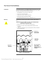
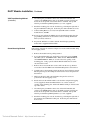
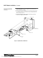
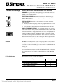
4004 Fire Alarm City Connect Card and DACT Module Installation Instructions Cautions and Warnings DO NOT INSTALL ANY SIMPLEX PRODUCT THAT APPEARS DAMAGED. Upon unpacking your Simplex product, inspect the contents of the carton for shipping damage. If damage is apparent, immediately file a claim with the carrier and notify Simplex. ELECTRICAL HAZARD - Disconnect electrical power when making any internal adjustments or repairs. Servicing should be performed by qualified Simplex Representatives. STATIC HAZARD - Static electricity can damage components. Therefore, handle as follows: 1. Ground yourself before opening or installing components (use the 553-484 Static Control Kit). 2. Keep uninstalled components wrapped in anti-static material at all times. RADIO FREQUENCY ENERGY - This equipment generates, uses, and can radiate radio frequency energy and if not installed and used in accordance with the instruction manual, may cause interference to radio communications. It has been tested and found to comply with the limits for a Class A computing device pursuant to Subpart J of Part 15 of FCC Rules, which are designed to provide reasonable protection against such interference when operated in a commercial environment. Operation of this equipment in a residential area may cause interference in which case the user at his own expense will be required to take whatever measures may be required to correct the interference. Overview The 4004 Fire Alarm System is capable of supporting either one City Connect Card (565-577, 565-999, or 566-078) or one DACT module. This publication covers the procedure for installing a city connect card into a 4004 Panel. It also covers the procedure for re-installing a 2080-9044 DACT into a 4004 Panel for existing jobs. For new DACT installations use the 4004-9810 DACT (565-626). Refer to the Contact Closure DACT (Digital Alarm Communication Transmitter) Installation Programming Instructions (574-049) for more information on the 4004-9810 DACT. In This Publication The following topics are covered in this publication: Topic See Page # Overview 1 City Connect Card Installation 2 DACT Module Installation 4 1999 Simplex Time Recorder Co., Gardner, MA 01441-0001 USA All specifications and other information shown were current as of publication, and are subject to change without notice. Technical Manuals Online! - http://www.tech-man.com 574-077 Rev. B City Connect Card Installation Introduction Mounting For all wiring information, use the 4004 Field Wiring Diagram (841-992). Also reference the Contractor Wiring Termination Label (519-698) inside the 4004 Door Panel. The label shows the following information: • The installation location of the city connect card. • The location of the wiring harness. • Harness interconnection with the system card. • The location of the city disconnect switches. • Programming information necessary to configure the card. To mount the city connect card, follow Steps 1 through 3 while referring to Figure 1. CAUTION: Disconnect 4004 Panel power at the breaker before installing the city connect card. 1. Remove the city connect card from the packing material. 2. Install the city connect card by securing it with four #6 Torx screws (supplied). 3. Connect the Cable Harness (733-875) from the City Connect Card (P1) to the System Board (P5). P6 1 2 3 4 P1 O N 3 21 O N 4 1 City Circuit 2 jumper plugs (P4 and P5) RP LE LE P4 1 RP RP 21 City Circuit 1 jumper plugs (P2 and P3) P5 P2 1 RP LE LE P3 Supervisory or trouble operation jumper plug (P6) 3 Disconnect Switches (SW1 and SW2) located on 565-577 and 565-999 only. The switches are not present on 566-078. TB1 CITY1+ CITY1- CITY2+ CITY2- Figure 1. City Connect Card Continued on next page 2 Technical Manuals Online! - http://www.tech-man.com City Connect Card Installation, Continued Jumper Settings The city connect card has jumper settings that select either the Remote Station (Reverse Polarity) Interface (see Table 1), which is the default jumper setting from the factory, or the Municipal Master (Local Energy) Interface. Jumper settings to configure the city connect card for the Remote Station Interface or the Municipal Master Interface are listed below. The city connect card has silk-screening that illustrates the jumpers and selectable configurations (“RP” = Reverse Polarity, “LE” = Local Energy). Table 1. Jumper Settings Municipal Master (Local Energy) Remote Station (Reverse Polarity) P2-1 to P2-2 P2-2 to P2-3 P3-7 to P3-8 P3-1 to P3-2 P3-9 to P3-10 P3-3 to P3-4 —— P3-5 to P3-6 P4-1 to P4-2 P4-2 to P4-3 P5-7 to P5-8 P5-1 to P5-2 P5-9 to P5-10 P5-3 to P5-4 —— P5-5 to P5-6 City Circuit 1 City Circuit 2 Note: City Circuit 2 can also be selected for Remote Station Supervisory or Trouble Operation (See Table 2) by setting the following jumpers. When City Circuit 2 is selected for Trouble Operation, City Circuit 1 reports Alarm only. Table 2. Operation of City Circuit 2 Supervisory Operation Trouble Operation P6-1 to P6-2 —— P6-3 to P6-4 P6-2 to P6-3 Switch Settings The City Connect Card (565-577 and 565-999 only) has two disconnect service switches (SW1 and SW2); the normal position for both switches is the active “ON” position. City Connect Card (566-078) does not have these switches. Power-up and Configuration Power-up the 4004 System and configure the city connect card using the programming instructions located on the Termination Wiring Label (519-698) inside the door. 3 Technical Manuals Online! - http://www.tech-man.com DACT Module Installation Introduction and Reference Information Note: The following installation procedures are for the Silent Knight Model 5128 only. CAUTION: Disconnect power for the 4004 Panel at the breaker before installing the DACT module. For all wiring information, use the Field Wiring Diagram (841-992). DACT modules mount to the 4004 Back Box in a physical location where the DACT status LEDs can be viewed from a cutout slot opening on the mounting plate. The Contractor Wiring Termination Label (519-698) located on the inside of the 4004 door panel does not directly indicate where the DACT module should be mounted. Instead the label illustrates the optional City Connect Card in the area where the cutout slot is located to view the DACT status LEDs. The door label also provides the programming information to configure the DACT into the 4004 System. There are two installation methods to mount the DACT module to the 4004 Back Box: using either VHB tape or screw mounting. Use the appropriate mounting method for your installation. If possible, install the DACT before terminating field wiring on the 4004 system cards. CAUTION: When installing the DACT module, be careful not to damage non-power limited and power limited wiring when removing or installing the mounting plate to/from the back box. Lay the mounting plate on a non-conductive, static free table when installing DACT module. VHB Tape Mounting Method Follow Steps 1 through 11 and refer to Figure 2 to mount a DACT module using VHB Tape. 1. Remove the module from its packing material. 2. Locate the DACT module onto the back box back wall so the green “POWER ON” LED, yellow “SYSTEM TROUBLE” LED, and red “PHONE LINE #1 and PHONE LINE #2” LEDs are over the cutout slot opening on the mounting plate. Using a pencil, trace the DACT module edge locations onto the back box back wall. 3. Remove the two bottom #6 Torx screws and loosen the two top #6 Torx screws that secure the 4004 Control Panel Mounting Plate to the back box. 4. Carefully remove the mounting plate from the back box by lifting it upward. Pull the plate left past the locking tab and forward to release the plate from the back box. 5. Attach two 8-inch long strips (approximate) of double sided VHB tape (supplied) to the back of the DACT module lengthwise. 6. Remove the protective paper and position the DACT module where the pencil tracing marks are located. Ensure the LED windows are over the cutout slot opening on the mounting plate and that the TELCO wiring is oriented at the top of the cabinet. Continued on next page 4 Technical Manuals Online! - http://www.tech-man.com DACT Module Installation, Continued VHB Tape Mounting Method (Continued) 7. Cut and strip the green Earth connect wire on the DACT module and connect to the 4004 Back Box using an 18 AWG green wire and wire nut. Isolate the circuit ground connection from P1-1 of DACT. The ground return is provided through Wiring Harness (733-897, supplied). 8. Install the mounting plate onto the back box by positioning the right side of the plate behind the locking tab. Secure the plate with four #6 Torx screws. 9. Connect Wiring Harness (733-897) from System Board P5 to DACT module P2, P5, and TB1. 10. Power-up and configure the 4004 System for the DACT module using the programming instructions located on the Contractor Wiring Termination Label (519-698) on the door. 11. Program the DACT in accordance with the installation/programming manual that is supplied with the DACT. Screw Mounting Method Follow Steps 1 through 11 and refer to Figure 2 to mount a DACT module using #4 self-tapping screws. 1. Remove the module from its packing material. 2. Locate the DACT module onto the back box wall so the green “POWER ON” LED, yellow “SYSTEM Trouble” LED, and red “PHONE LINE #1” and “PHONE LINE #2” LEDs are over the cutout slot opening on the mounting plate. Using a pencil, mark the DACT module hole locations onto the back box wall. 3. Remove the two bottom #6 Torx screws and loosen the two top #6 Torx screws that secure the 4004 Control Panel Mounting Plate to the back box. 4. Carefully remove the mounting plate from the back box by lifting it upward. Pull the plate left past the locking tab and forward to release the plate from the back box. 5. Drill four .099 holes with a #11 drill where the pencil locations are positioned for the self-tapping screws. 6. Install and secure the DACT module to the back box using #4 self-tapping screws (supplied). Ensure the LED windows are over the cutout slot opening on the mounting plate and that the TELCO wiring is oriented at the top of the cabinet. 7. Cut and strip the green Earth connect wire on the DACT module and connect to the 4004 Back Box using an 18 AWG green wire and wire nut. Isolate the circuit ground connection from P1-1 of DACT. The ground return is provided through Wiring Harness (733-897, supplied). 8. Install the mounting plate onto the back box by positioning the right side of the mounting plate behind the locking tab. Secure the plate with four # 6 Torx screws. Continued on next page 5 Technical Manuals Online! - http://www.tech-man.com DACT Module Installation, Continued Screw Mounting Method (Continued) 9. Connect Wiring Harness (733-897, supplied) from System Board P5 to DACT module P2, P5, and TB1. 10. Power-up and configure the 4004 System for the DACT module using the programming instructions located on the Contractor Wiring Termination Label (519-698) on the door. 11. Program the DACT in accordance with the installation/programming manual that is supplied with the DACT. REGISTRATION LABEL DACT MODULE MOUNTING LOCATION TELCO WIRING DACT MODULE LEDS DACT MODULE MOUNTING PLATE CUT OUT SLOT OPENING Figure 2. Exploded View of 4004 Panel 574-077 Rev. B Technical Manuals Online! - http://www.tech-man.com