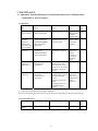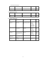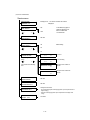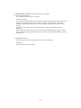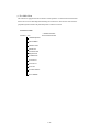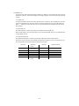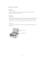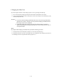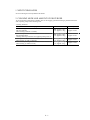
1
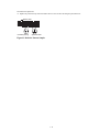
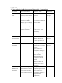
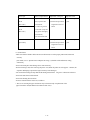
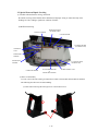
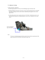
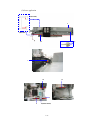
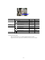
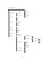
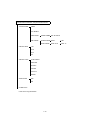
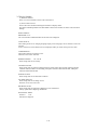
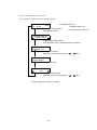
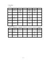
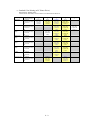
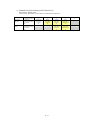
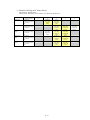
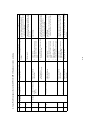
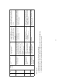
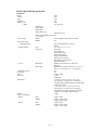
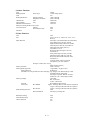
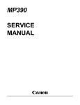
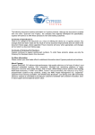
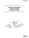
PIXMA MP110/130
SERVICE
MANUAL
REVISION 0
HY8-13A2-000
COPYRIGHT©2004 CANON INC. CANON PIXMAMP110/130 NOVEMBER 2004
Scope
This manual has been issued by Canon Inc., to provide the service technicians of this product with the
information necessary for qualified persons to learn technical theory, installation, maintenance, and repair
of products. The manual covers information applicable in all regions where the product is sold. For this
reason, it may contain information that is not applicable to your region.
Revision
This manual could include technical inaccuracies or typographical errors due to improvements or changes
made to the product. When changes are made to the contents of the manual, Canon will release technical
information when necessary. When substantial changes are made to the contents of the manual, Canon will
issue a revised edition.
The following do not apply if they do not conform to the laws and regulations of the region where the
manual or product is used:
Trademarks
Product and brand names appearing in this manual are registered trademarks or trademarks of the
respective holders.
Copyright
All rights reserved. No parts of this manual may be reproduced in any form or by any means or translated
into another language without the written permission of Canon Inc., except in the case of internal business
use.
Copyright © 2004 by Canon Inc.
CANON INC.
Inkjet MFP Quality Assurance Div.
5-1 Hakusan 7-Chome, Toride-city, Ibaraki 302-8501, Japan
I. MANUAL OUTLINE
This manual consists of the following three parts to provide information necessary to service the PIXMA
MP110/MP130:
Part 1: Maintenance
Information on maintenance and troubleshooting of the PIXMA MP110/MP130
Part 2: Technical Reference
New technology and technical information such as FAQ's (Frequently Asked Questions) of the PIXMA
MP110/MP130
Part 3: Appendix
Block diagrams PIXMA MP110/MP130
Reference:
This manual does not provide sufficient information for disassembly and reassembly procedures. Refer
to the graphics in the separate Parts Catalog.
II. TABLE OF CONTENTS
Page
1-1
1-1
1-2
1-3
1-3
1-4
1-5
1-5
1-8
1-8
1-8
1-8
1-9
1-12
1-12
1-14
1-16
1-19
1-21
1-25
1-29
1-30
1-30
1-30
1-31
Part 1: MAINTENANCE
1. MAINTENANCE
1-1. Adjustment, Periodic Maintenance, Periodic Replacement Parts, and Replacement
Consumables by Service Engineer
1-2. Customer Maintenance
1-3. Product Life
1-4. Special Tools for Service
1-5. Serial Number Location
2. LIST OF ERROR DISPLAY / INDICATION
2-1. Users Error Messeges
2-2. User Error Codes
2-3. Service Error Codes
2-4. New Error Codes and Recovery Methods
2-5. Warnings
2-6. Troubleshooting by Symptom
3. REPAIR
3-1. Notes on Service Part Replacement (and Disassembling / Reassembling)
3-2. Special Notes on Repair Servicing
(1) Flexible cable and harness wiring, connection
(2) Notes on disassembly
3-3. Adjustment / Settings
(1) Paper feed motor adjustment
(2) Grease application
(3) Waste ink counter setting
3-4. User Data Flow
3-5. Service Switches
(1) Hardware switches
(2) Service data overview
(3) Service data registration / setting method
(4) Service data menu
(5) New service data added to this model
3-6. Test Mode
(1) User test print Functions
(2) Test mode overview
(3) Test mode Menu
3-7. Flash ROM Version Upgrade
4. CLEANING YOUR MACHINE
4-1 Exterior
4-2 Scanning Unit
5. PRINTER TRANSPORTATION
Page
2-1
2-1
2-2
2-6
Part 2: TECHNICAL REFERENCE
1. NEW TECHNOLOGIES
2. CLEANING MODE AND AMOUNT OF INK PURGED
3. PRINT MODE
4. FAQ (Problems Specific to the PIXMA MP110/ MP130 and Corrective Actions)
Page
3-1
3-2
Part 3: APPENDIX
1. BLOCK DIAGRAM
2. PIXMA MP110/ MP130 SPECIFICATIONS
Part 1
Maintenance
1. MAINTENANCE
1-1 Adjustment, Periodic Maintenance, Periodic Replacement Parts, and Replacement
Consumables by Service Engineer
(1) Adjustment
Approx.
Item
Timing
Purpose
Tool
Country setting
(Service Mode)
- At MAIN BOARD
ASS’Y replacement
To set the country.
1 min.
Registration of
waste ink
absorption
amount at the
waste ink counter
(Service Mode)
Print head
alignment
- At MAIN BOARD
ASS’Y replacement
- At INK ABSORBER
(HY7-2819/2820)
replacement
To register the waste ink
absorption amount at the
waste ink counter.
None
(Service Mode
MARKET
MODEL-JPN)
None
(Service Mode
COUNTER
ACSESS)
- At print head
replacement
- At MAIN BOARD
ASS’Y replacement
To compensate the print
head landing-in position
error.
2 min.
Paper feed motor
installation
adjustment *1
-At PAPER FEED
MOTOR UNIT
replacement
Grease
application
-At CARRIAGE UNIT
replacement
-At MAIN UNIT
replacement
To adjust the belt tension.
(Install the paper feed
motor unit by moving in
the direction to stretch the
belt tightly with proper
tension.)
-To apply grease to the
carriage sliding portion
and the carriage rail
portion.
- To apply grease to the
blade.
- To apply grease to the
Eject Roller sliding
portion.
None
- Main body
buttons
- Computer
settings via
the printer
driver
None
-FLOIL
KG-107A
(QY9-0057)
-MOLYKOTE
PG641
(CK-0562)
2 min.
time
1 min.
2 min.
*1: Caution for the paper feed motor installation adjustment
The screws securing the paper feed motor may be loosened only at replacement of the paper feed motor unit.
(2) Periodic maintenance
Item
Timing
Purpose
Tool
Approx.
time
None
1-1
(3) Periodic replacement parts
Item
Timing
Purpose
Tool
Approx.
time
None
(4) Replacement consumables
Item
Timing
Purpose
Tool
Approx.
time
None
1-2 Customer Maintenance
Item
Timing
Purpose
Tool
Print head
alignment
At print head
replacement.
To compensate the print
head landing-in position
error.
Print head cleaning
When print quality is
not satisfying.
To improve nozzle
conditions.
Print head
refreshing
When print quality is
not satisfying (and not
improved by print head
cleaning).
To improve nozzle
conditions.
- Main body
buttons
- Computer
performed by
the automatic
settings via the
printer driver
- Main body
buttons
- Computer
settings via the
printer driver
- Main body
buttons
- Computer
setting via the
printer driver
Ink tank
replacement
When an ink tank
becomes empty. (At No
Ink error)
When paper cannot be
fed properly.
Paper feed roller
cleaning
Approx.
time
3 min.
30 sec. 1 min.
1 min. 1 min.
and half
2 min.
-
-
To clean the paper feed
rollers.
Main body
buttons
1-2
2 min.
1-3 Product Life
(1) Main body
At any of the following (I) to (II), whichever comes first.
(I) Print Volume: 4,000 pages
BK: 2,000 pages (in printing A4, Black 1,500 character standard document pattern)
CL: 1,200 pages (in printing A4, 7.5 % duty per color pattern)
120 pages (in printing A4, photo, borderless)
80 pages (in printing L-size, photo, borderless)
600 pages (in printing Postcard, photo, borderless)
The figures of Print Volume shown above indicate an assumed breakdown when an average user prints 4,000
pages.
(II) Years of use:
3 years of use
(2) Print head
Item
Structure
Print head
Details
4 color integrated head (Detachable ink tanks)
Bk: 320 nozzles, 2-column vertical array
C/M/Y: 128 nozzles/color, 2-column vertical array/color
Droplet: Bk 30pl, Col 5pl/2pl
Bk (pigment), Col: C, M, Y (high coloration)
BCI-24Black, BCI-24Color
Approx. 58 g (ink tanks are not included)
Service parts (ink tanks are not included)
Service parts number: QY6-0054
4,000 pages (the same as the main body)
Ink colors
Ink tanks
Weight
Form of supply
Product life
(3) Ink tanks
BCI-24Black:
approx. 300 pages (JEIDA standard patternJ1, plain paper, standard mode)
approx. 520 pages (ISO JIS-SCID No. 5 pattern, plain paper, standard mode)
BCI-24Color:
approx. 170 pages (ISO JIS-SCID No. 5 pattern, plain paper, standard mode)
1-4 Special Tools for Service
Name
Tool No.
Purpose
Remarks
MOLYKOTE
CK-0562-000
To be applied to the lift cam base upper
In common with
gear and the lift cam shaft sliding portion.
other models.
To be applied to the carriage sliding
In common with
portion, the carriage rail portion, and the
other models.
PG641
FLOIL KG-107A
QY9-0057-000
paper guide flapper’s sliding portion.
1-3
1-5 Serial Number Label Location
The middle on the rear cover
1-4
2. LIST OF ERROR DISPLAY / INDICATION
Error Messages
Look for the applicable error message and execute the appropriate countermeasures.
2-1 User’s error messages
Look for the applicable error message and execute the appropriate countermeasures.
“BLACK INK LOW”
Cause: The ink level in the black ink tank is low.
Solution: Make sure you have a new black ink tank ready to replace the used one when ink runs out. If the
machine stops printing when copying or photo printing, you can continue printing by pressing the
[OK] button. However, note that ink may run out. If print quality deteriorates or the print out is blank,
replace the ink tank.
“CANNOT USE CARD TURN OFF AND ON”
Cause: You have inserted a memory card incompatible with the machine or a damaged memory card into the
card slot.
Solution: Remove the memory card from the card slot, and then turn the power OFF and ON again.
“CARD READ ERROR TURN OFF AND ON”
Cause: The data on the memory card may be inaccessible.
Solution: Check the data on the memory card in your digital camera.
Check the connection between the multi-card board and the MAIN board.
Replace the multi-card board.
Replace the MAIN board.
1-5
“CARTRIDGE JAMMED”
Printing position compensation failed
Cause: Carriage movement prevented by one of the following.
Damaged or deformed carriage shaft.
Insufficient grease.
Solution: Replace the carriage shaft.
Replace the deformed parts.
Apply more grease.
Cause: Bi-directional print displacement compensation failed because the carriage motor is out of step, or
some similar reason.
Solution: Replace the carriage motor.
Home position error
Cause: Tried to stop the carriage unit that has been moving or to move the carriage unit at a pause by force.
Solution: Do not touch the carriage unit other than the carriage at the cartridge replacement position.
Cause: Foreign body in carriage section.
Solution: Open flatbed ass’y and remove the foreign body.
Cause: Loose carriage belt.
Solution: Replace the carriage unit.
Cause: Carriage motor does not work.
Solution: Switch Power OFF/ON.
Replace the carriage motor.
Cause: The position of the carriage cannot be detected (due to smears on the carriage encoder film or a MAIN
board failure).
Solution: Switch Power OFF/ON.
Wipe the carriage encoder film with a cloth moistened with alcohol.
Replace the carriage unit.
Replace the carriage encoder film.
Replace the MAIN board.
“CHECK PRINTER”
Cause: The printer’s internal unit has malfunctioned.
Solution: Clear the paper jam.
Press the [OK] button.
Reinstall the print head.
Turn the power off and on.
1-6
“COLOR INK LOW”
Cause: The ink level in the color ink tank is low.
Solution: Make sure you have a new color ink tank ready to replace the used one when ink runs out. If the
machine stops printing when copying or photo printing, you can continue printing by pressing the
[OK] button. However, note that ink may run out. If print quality deteriorates or the print out is blank,
replace the ink tank.
“COVER OPEN”
Cause: You opened the scanning unit (printer cover) during an operation.
Solution: Close the scanning unit (printer cover).
Cause: Cover sensor failure.
Solution: Replace the cover sensor.
“PUT IN CARTRIDGE”
Cause: The print head is not set in this machine.
Solution: Set the print head.
“PLEASE CLEAR PAPER JAM AND PRESS [OK]”
Cause: There is a recording paper jam.
Solution: Clear the recording paper jam and press the [OK] button.
“PLEASE LOAD PAPER AND PRESS [OK]”
Cause: The multi-purpose tray is empty.
Solution: Load paper in the multi-purpose tray. Make sure that the stack is below the paper limit mark. Then
press the [OK] button.
“WASTE NEAR FULL”
Cause: The waste ink tank absorber (which holds the ink used for print head cleaning) is nearly full.
Solution: If the “CHECK PRINTER” message is displayed, select “COUNTER ACCESS” in the Service Mode
and input “0” at the waste ink counter. After that, replace the ink tank absorber.
“WRONG CARTRIDGE”
Cause: The print head is not installed correctly.
Solution: Install the print head correctly.
Cause: The print head failure.
Solution: Replace the print head.
1-7
2-2 User Error Codes
None.
2-3 Service Error Codes
None
2-4 New Error Code and Recovery Methods
None
2-5 Warnings
Main body no LED indications.
Displayed warning
Remarks
None
None
1-8
2-6 Troubleshooting by symptom
General
errors
Symptom
Solution
The unit does not power on.
(1) Check the power cord connection.
(2) Check the connection between the
MAIN board (J5) and the power
supply unit.
(3) Replace the power supply unit.
(1) Check the connection between the
Operation panel unit and the MAIN
board (J4).
(2) Replace the SCANNER unit.
(3) Replace the MAIN board.
(1) Check the connection between the
Operation panel unit and the MAIN
board (J4).
(2) Replace the SCANNER UNIT.
(3) Replace the MAIN board.
(1) Check the connection between the
paper feed motor and the MAIN board
(J7).
(2) Replace the paper feed motor.
(3) Replace the MAIN board. *1
(1) Check whether there is any broken
part or foreign matter in the paper feed
section.
(2) Replace the SEPARATION UNIT.
(3) Replace the MAIN board. *1
(1) Check the connection between the
carriage motor and the MAIN board
(J6).
(2) Replace the carriage motor.
(3) Replace the MAIN board. *1
(1) Remove the print head and reinstall
it.
(2) Perform the cleaning on the print
head five times with the cleaning
operation and print out the nozzle
check pattern. Visually cheek the test
print for non-discharge of ink from
nozzle. (Fig. 1-1)
(3) Replace the print head. *2
(4) Replace the appropriate ink tank.
(5) Replace the purge unit.
(6) Replace the carriage unit.
(7) Replace the MAIN board. *1
Nothing is displayed in LCD
display.
The buttons on the
operation panel do not
work.
Printing
operation
errors
Paper is not fed properly.
(The Paper feed motor does
not run.)
Paper is not picked up from
the auto sheet feeder.
The carriage motor does not
run.
Printing
quality
errors
- Nothing is printed at all.
- Colors are not printed.
1-9
Remarks
Symptom
Solution
Remarks
(1) Remove the print head and reinstall
it.
(2) Perform the cleaning on the print
head five times with the cleaning
operation and print out the nozzle
check pattern. Visually check the
test print for non-discharge of ink
from nozzle. (Fig. 1-1)
(3) Replace the print head. *2
(4) Replace the appropriate ink tank.
(5) Replace the purge unit.
(6) Replace the carriage unit.
(7) Replace the MAIN board. *1
(8) Replace the MAIN board.
(1) Feed a few sheets of paper through
Soiled paper
the machine.
(2) Clean the paper feed section with a
clean cloth or a clean cotton bud.
Pictures or characters are
<Carriage scanning direction>
(1) Check whether grease is applied to
extended in print results.
the carriage encoder film.
(2) Carefully and gently wipe the
carriage encoder film using lint-free
paper moistened with alcohol.
Do not scratch the surface of the
carriage encoder film.
(3) Replace the carriage encoder film.
(4) Replace the carriage unit.
<Paper feeding direction>
(1) Check whether grease is applied to
the paper feed encoder film.
(2) Carefully and gently wipe the paper
feed encoder film using lint-free
paper moistened with alcohol.
Do not scratch the surface of the
paper feed encoder film.
(3) Replace the paper feed encoder
film.
(4) Replace the timing sensor unit.
Scanning
(1) Check the connection between the
The Contact Sensor drive
errors
contact sensor drive motor and the
motor does not run.
MAIN board (J8).
(2) Replace the scanner unit.
(3) Replace the MAIN board.
(1) Check the connection between the
The Scanned images are
abnormal.
contact sensor and the MAIN board
(J8).
(2) Replace the scanner unit.
(3) Replace the MAIN board.
The image has vertical stripes. (1) Clean the document glass.
The colors or the brightness of (2) Check the connection between the
contact sensor and the MAIN board
the image is abnormal.
(J8).
(3) Replace the scanner unit.
(4) Replace the MAIN board.
*1 The absorption amount of the waste ink absorber is set based upon the amount that the BJ cartridge has
ejected. The settings of the waste ink capacity are stored in EEPROM of MAIN board. When replacing the MAIN
board, check the waste ink capacity before the replacement, and input the waste ink capacity at the new MAIN
Printing
quality
error
Blotches or blank ink appears
after cleaning the print head.
Lines that the printing data
does not contain are printed.
1-10
board after the replacement.
*2 Replace the print head only when the machine does not recover after refreshing the print head twice.
Missing dots
Unstable printing
Splashed dots
Figure1-1 Defective Pattern Sample
1-11
3. REPAIR
3-1 Notes on Service Part Replacement (and Disassembling / Reassembling)
Service part
Notes on replacement*1
Adjustment / settings
Operation check
MAIN BOARD
- Before removal of the MAIN
<After replacement>
- Nozzle check
ASS’Y
board ass'y, remove the power
1) All clear.
patten print
(HY7-2810/2811)
cord, and allow for approx. 1
2) Register the waste ink
- Printing via USB
minute (for discharge of
absorber capacity at
capacitor's accumulated
COUNTER ACCESS in the
charges), to prevent damages
Service Mode.
connection
3) Set MARKET MODEL in
to the MAIN board ass'y.
[For details, see 3-2. Special
the Service Mode.
Notes on Repair Servicing (2)
[For details of 1) to 3)
Notes on disassembly.]
above, see 3-5. Service
Switches]
5) Set MECHANICAL SET in
the Service Mode.
INK ABSOBER
<After replacement>
- Nozzle check
(HY7-2819/2820)
1) Register the waste ink
patten print
counter. [For details, see
3-5. Service Switches]
CARRIAGE UNIT
<At replacement>
- Nozzle check
(HY7-2844)
1) Apply grease to the sliding
patten print
portion.
[For details, see 3-3.
Adjustment / Settings (3)
Grease application.]
<After replacement>
1) Perform the print head
alignment in the User
Mode.
2) Shipment Settings [For
details, see 3.5. Service
Switches.]
PAPER FEED
<At replacement>
- The screws securing the
1) Adjust the paper feed motor.
MOTOR UNIT
paper feed motor are allowed
(HY7-2826)
to be loosened. (DO NOT
[For details, see 3-3.
loosen any other red screws.)
Adjustment / Settings (1)
Paper feed motor
adjustment.]
1-12
Service part
Notes on replacement*1
Adjustment / settings*2
Operation check
TIMING SLIT STRIP
-Upon contact with the
<After replacement>
- Nozzle check patten
FILM
film, wipe the film
(HY7-2821)
with ethanol.
TIMING SLIT DISK
1) Perform the print head
print
alignment in the User
Mode.
- Confirm no grease is
FILM
on the film. (Wipe off
(HY7-2817)
any grease thoroughly
with ethanol.)
- Do not bend the film
PRINT HEAD
<After replacement>
(QY6-0054))
1) Perform the print head
- Nozzle check patten
print
alignment in the User
Mode.
*1: General notes:
- Make sure that the flexible cables and wires in the harness are in the proper position and connected
correctly.
[For details, see 3-2. Special Notes on Repair Servicing, (1) Flexible cable and harness wiring,
connection.]
- Protect electrical parts from damage due to static electricity.
- Before removing a unit, after removing the power cord, allow the printer to sit for approx. 1 minute (for
capacitor discharging to protect the logic board ass'y from damages).
- Do not touch the timing slit strip film and the timing slit disk film. No grease or abrasion is allowed.
- Protect the units from soiled with ink.
- Protect the housing from scratches.
- Exercise caution with the red screws, as follows:
i. The screws securing the paper feed motor may be loosened only at replacement of the
paper feed motor unit (DO NOT loosen them in other cases).
1-13
3-2 Special Notes on Repair Servicing
(1) Flexible cable and harness wiring, connection
Be careful of wiring of the flexible cables and harness. Improper wiring or connection may cause
breakage of a line, leading to ignition or emission of smoke.
(I) MAIN board wiring
CONTACT SENSOR
OPERATION PANEL
(SCANNER UNIT)
COVER SENSOR
SCANNER MOTOR
(SCANNER UNIT)
CARRIAGE
UNIT
PAPER FEED
SENSOR
PAPER EDGE
SENSOR
To CARD READER
BOARD JUSB1
CARRIAGE MOTOR
LF ENCODER SENSOR
&
PAPER FEED MOTOR
POWER SUPPLY UNIT
(2) Notes on disassembly
As a rule, refer to the Parts Catalog for instructions on how to disassemble and assemble the machine.
The following describes notes on disassembling.
(I) Claws when removing the front right cover or the front left cover
A
1-14
Each of the front right cover or the front left cover has 4 claws.
Since the claws of A are located back of the paper feed section, remove the covers at the A
claws from inside by hand as shown below.
1-15
3-3. Adjustment / Settings
(1) Paper feed motor adjustment
The following adjustment is necessary when installing the paper feed motor unit.
1) When installing the motor unit, secure the screws by moving in the direction to stretch the
belt tightly with proper tension (in the direction indicated by the light blue arrow in the
figure below).
2) After replacement, be sure to perform the Service Test Print. Confirm that no noise or no
abnormal print result (due to an unfastened belt, a step-out motor, misalignment of gear teeth)
occurs.
Screws securing the
Paper Feed Motor
Note:
The screws securing the paper feed motor may be loosened only at replacement of the
paper feed motor unit. DO NOT loosen them in other cases.
1-16
(2) Grease application
1 (Rear Side)
2
3 (Rear Side)
4, 5
6
7
12
10
9
8
11 (Bottom Surface)
1-17
13
Parts to be applied
Locations
Grease/Oil Type
PRINTER FRAME
1
2
CARRIAGE UNIT Sliding Portion (back surface)
Chassis Surface
FLOIL KG107
FLOIL KG107
CARRIAGE RAIL
3
4
CARRIAGE UNIT Sliding Portion (back surface)
CARRIAGE UNIT Sliding Portion (front surface)
FLOIL KG107
FLOIL KG107
240 - 360 mg
60 - 140 mg
5
6
CARRIAGE UNIT Sliding Portion (bottom surface)
IDLER PULLY Sliding Portion
FLOIL KG107
MOLYKOTE PG641
35 - 60mg
IDLER PULLY
PLATEN UNIT
7
EJECT ROLLER Sliding Portion
FLOIL KG107
BOTTOM FRAME ASS'Y
8
PURGE UNIT Sliding Portion
MOLYKOTE PG641
9
PURGE UNIT Sliding Portion
MOLYKOTE PG641
10
PURGE UNIT Sliding Portion
MOLYKOTE PG641
4 - 12 mg
9 - 18 mg
9 - 18 mg
9 - 18 mg
11
12
PURGE UNIT Sliding Portion
PURGE UNIT Sliding Portion
MOLYKOTE PG641
MOLYKOTE PG641
13
CARRIAGE UNIT Sliding Portion
MOLYKOTE PG641
Amount
60 - 140 mg
9 - 18 mg
4 - 12 mg x 2
places
TRIGGER ARM
x 5 places
Oil film
9 - 18 mg
4 - 12 mg
(3) Waste ink counter setting
When the MAIN board ass’y is replaced, register the waste ink counter.
Register the waste ink counter from COUNTER ACCESS in the Service Mode.
1-18
3-4 User Data Flowchart
Press the COPY button, and press the Menu button.
25% MIN.
95% A4 -> LTR
1.ENLARGE/REDUCE
PRESET RATIO
*100%
170% 5"x7" -> LTR
2.PAPER SIZE
ZOOM - 25% - 400%
212% 4"x6" -> LTR
*LTR
400% MAX.
4"x6"
5"x7"
A4
3.PAPER TYPE
*PLAIN PAPER
HIGH RES.
PH PRO
OTHER
4.DENSITY
LT
DK
5.IMAGE QUALITY
*NORMAL
FINE (PHOTO)
FAST
6.SPECIAL COPY
*NONE
BDERLESS COPY
7.USER DATA
1.INK VOLUME
1.LOWINK WARNING
ON
OFF
2.INKCOUNT RESET
BLK INK CHANGED?
YES=[ - ]
NO=[ + ]
COL INK CHANGED?
YES=[ - ]
NOZZLE CHECK
2.MAINTENANCE
NO=[ + ]
ALIGN HEAD
CLEANING
HEAD REFRESHIN
ROLLER CLEANIN
3.QUIET PRINTING
OFF
ON
4.XTENSION AMUNT
SMALL
LARGE
1-19
Press the Photo Print button, and press the Menu button.
1.PHOTO PRINT
INDEX
ALL IMAGES
2.SELECT SIZE
SINGLE IMG
IMAGE NUMBE NO. OF PRINTS
SEL RANGE
FRAME RANGE FIRST
LAST
DATE RANGE
DATE: To
LTR
4"x6"
5"x7"
A4
3.SELECT TYPE
PLAIN PAPER
HIGH RES.
GLOSSY
PH PRO
PH PLUS
OTHER
4.PRINT DATE
OFF
ON
5.USER DATA *
*: Refer to the Copy Mode Menu.
1-20
DATE: From
3-5 Service Switches
(1) Hardware Switches
There is no service hardware switch on the Circuit board.
(2) Service Data Overview
Service data can be checked and changed with items on display menus.
The effective SSSWs/parameters and their default values in this machine are shown in Service Menu
Settings.
SERVICE MENU
FIRMWARE: xx.xx
The version number of ROM mounted on the main unit is displayed.
LANG. SELECT?
These setting items are for changing language display, such as language can be selected or cannot be
selected.
If NO=>YES is set, LANG.SELECT screen is displayed when you switch on the power next time.
CARD PROTECT?
These setting items are for design review.
Therefore, never select “NO” here.
MARKET MODEL?
US / OT /JP
These setting items are for country.
COUNTER ACCESS
These setting items are used for inputting actual use results of the main unit after replacing SPCNT.
*Number of Print, Number of CIS reading, Absorption Amount to Main Ink Absorber, Absorption
Amount to Platen Ink Absorber
NVRAM ACCESS.
These setting items are for main unit evaluation.
FACTORY DEFAULT
These setting items are for design review.
Therefore, never select “NO” here.
MECHANICAL SET
These setting items are used after completing service maintenance.
Always operate after completing maintenance.
DIAGNOSTIC MENU
Firmware:
xx.xx
Test Mode is displayed.
1-21
(3) Service Data Registration/ Setting Method
Service data can be registered/set by the following operations:
100% NORMAL
STANDBY(Copy mode)
* If MARKET MODEL is OT,
LTR PLAIN
1) User data mode selection
Recording paper size will be A4.
Press the Menu button.
01
1.ENLARGE/REDUCE
PRESET RATIO
2) Service data mode selection
Press the SCAN, COPY, and SCAN buttons in sequence.
SERVICE MENU
FIRMWARE: xx.xx
3) Menu item selection
Select the menu item by pressing the
or
button.
or
button.
SERVICE MENU
MARKET MODEL?
Press the OK button.
MARKET MODEL
*US
4) Data registration/setting
Select the menu item by pressing the
Press the Stop button to return to standby.
1-22
(4) Service Data Menu
Service menu
SERVICE MENU
FIRMWARE: xx.xx
Example) 01.03 The version mounted in the machine
is displayed.
SERVICE MENU
LANG. SELECT?
NO
-
+
In User Mode, languages to
switch are displayed or not.
US/OT = Default: YES
JP = Default: NO
YES
SERVICE MENU
CARD PROTECT?
Not used
SERVICE MENU
MARKET MODEL?
US
-
+
Market setting
OT
JP
SERVICE MENU
COUNTER ACCESS
After pressing COPY
button
-
+
input a value for the following
item.
PRINT PAGE COUNT
0 /
0
No. of Print
SCAN PAGE COUNT
0 /
0
No. of CIS reading
ABS-M DOT COUNT
0
ABS-P DOT COUNT
0
SERVICE MENU
NVRAM ACCESS ?
SERVICE MENU
FACTORY DEFAULT ?
SERVICE MENU
MECHANICAL SET ?
DIAGNOSTIC MENU
Firmwqre: xx.xx
Absorption Amount to Main Ink
Absorber
Absorption Amount to Platen Ink
Absorber
Not used
Not used
Settings after maintenance
- Lift up ASF pressure plate to the shipping position (to avoid permanent set in
fatigue of sping).
- Set Pump to the shipping position (to avoid permanent set in fatigue of the
Pump)
Test mode
1-23
(5) New SSSWs/Parameters Added to This Model
No SSSWs/parameters are newly added to this model.
1-24
3-6 DIAGNOSTIC MENU (hereinafter referred to as Test Mode)
(1) User Test Print Functions
User enabled Test print functions are as follow.
Nozzle check pattern
If you find a nozzle pattern indistinct or partially missing when you conduct this test print, do the head
cleaning. If the symptom is not solved even after the cleaning is done three times, do the head
refreshing. If the head refreshing does not solve the symptom, replace the BJ cartridge or the ink
cartridge.
To print the nozzle check pattern, press the Menu button several times until USER DATA is
displayed.
Press the right cursor button or the left cursor button to select MAINTENANCE, and press the OK
button. Press the right cursor button or the left cursor button to select NOZZLE CHECK, and press
the OK button.
(2) Test Mode Overview
Test mode can be executed by following the menu items from the display.
PANEL test
Tests the functions of operation panel
1-25
(3) Test Mode Menu
This machine is equipped with the test mode to check operations of various functions listed below.
Please refer to Service Data Registration/Setting for instructions to select the test mode. Press the
[Stop/Reset] button and then the [ON/OFF] button to end the test mode.
DIAGNOSTIC MENU
Firmware: xx.xx
* ' indicates that these
are not used in the field.
1.CSLED Adjustme
2.Print COMET*
4.FB Scan Test*
9.Panel Test
10.Scanner Self*
Diagnosis Test
11.DRAM Test*
12.CR Run-in*
13.PF Run-in*
14.PF Life*
15.Check Sensors*
16.ALL RUNIN*
1-26
a) PANEL Test
If you select test menu in the TEST mode, PANEL test is displayed. To select the test menu, press the
OK button. In this test, check that the display, LED lamps, and keys on the control panel are operating
correctly.
a-1) Display test
If you press OK button in the menu of the operation panel, 16 letters of “H” are displayed in two lines.
If you press OK button one more time, all the LCD dots are displayed. If you press OK button once
again, “_” is displayed. Verify that there are no LCD dots which fail to be displayed by performing
this operation.
a-2) LED lamp test
The LED lamp test is selected by pressing the OK button after the display test.
When the OK button is pressed, all the lamps on the control panel light. Check for any LED that does
not light during the test.
a-3) Operation button test
The Operation button test is selected by pressing the OK button after the LED lamp test.
In this test, you press the key corresponding to the displayed character to put it out. The table giving
the correspondence between the characters and the keys is below.
Character
P
S
M
+
B
S
Operation
button
Photo Index
Sheet button
SCAN button
Menu button
+ button
Black button
Stop/Reset
button
1-27
Character
Operation button
C
COPY button
P
O
C
O
PHOTO button
- button
OK button
Color button
ON/OFF button
9. PANEL TEST
Press the OK button
HHHHHHHHHHHHHHHH
HHHHHHHHHHHHHHHH
H pattern display
Press the OK button
All LCD dots display
Press the OK button
________________
_ pattern display
________________
Press the OK button
LED TEST
All LED lamps light up
Press the OK button
When a button is pressed, the
corresponding character goes out
KEY TEST
PCSPM-+OBCSO
Press the OK button
OK
Press the Stop/Reset key to end the test.
1-28
3-7 Upgrading the version of flash ROM
To upgrade the version of flash ROM, always down load via USB interface.
<Flash ROM upgrading file>
The flash ROM upgrading file will be distributed in SSIS at the timing of upgrading the version.
<Upgrading Procedure>
The detailed upgrading procedure will be introduced by a Service Information bulletin when the
version is upgraded.
[Prerequisite (reference)]
- Printer to Personal Computer:
Connect via USB cable. (Connect only one printer to the computer.)
- Environment to be used, OS:
Windows 2000/XP
- Printer driver:
Should be installed in advance.
1-29
4. Cleaning Your Machine
4-1 Exterior
Main Unit Outer Covers
Dampen a soft cloth with water or a neutral detergent diluted with enough water, and wring it
thoroughly. Wipe the covers with the cloth.
4-2 Scanning Unit
Document Glass
Open the pressure plate. Dampen a clean cloth and wring it thoroughly. Wipe the document glass with
the cloth. Then wipe the document glass with a dry soft cloth well, so that no stain of the wet cloth
remains on the glass. You may use a neutral detergent diluted with water if the glass is very dirty.
Document Cover
Open the pressure plate. Dampen a clean cloth and wring it thoroughly. Wipe the document cover
with the cloth.
Document Cover
Document Glass
1-30
5. Shipping the Main Unit
If you must ship the machine as after making repairs, be sure to go through the following:
1) See to it that the BJ cartridge (print head) and the ink tank remain fitted in the carriage.
2) Press the ON/OFF button to turn off the power, and fix the carriage in its home position; then,
disconnect the power cord.
Attention:
(1) If you leave the BJ cartridge (print head) alone on its own, the ink (especially black
pigment ink) can start to cake. Be sure to keep the BJ cartridge (print head) fitted in
the carriage in the course of shipment.
(2) On the other hand, if the carriage is not fixed to its home position, it can move
right/left during shipment, possibly importing stress on the carriage flexible cable, or
causing ink leakage.
Memo:
If you ship the BJ cartridge (print head) alone, perform the following procedure.
1) Install both the color and the black ink tanks (to avoid nozzle inside dried up).
2) Install the protective cap that was attached when you installed the BJ cartridge (print head) (to
avoid damage on the face of print head caused by impact, etc.).
1-31
Part 2
Technical Reference
1. NEW TECHNOLOGIES
No new technologies are newly added to this model.
2. CLEANING MODE AND AMOUNT OF INK PURGED
To prevent printing problems due to bubbles, dust, or ink clogging, print head cleaning is performed before the
start of printing, except in the following cases:
<Cleaning mode list>
Cleaning type
Manual cleaning
Dot count cleaning
Timer cleaning (24 hours to 2 weeks)
Print head replacement
Ink tank replacement
Cleaning when the print head is not capped at printer power on
Cleaning on arrival at user
Timer cleaning (2 week to 3 months)
Print head deep cleaning
Timer cleaning (3 months or more)
2-1
Amount of ink used
Time required
BK: Approx. 0.12 g
CL: Approx. 0.14 g
Approx. 40 sec.
BK: Approx. 0.42 g
CL: Approx. 0.52 g
Approx. 45 sec.
BK: Approx. 0.42 g
CL: Approx. 0.52 g
BK: Approx. 1.5 g
CL: Approx. 2.2 g
Approx. 60 sec.
Approx. 70 sec.
3. Print Mode
(1) Copy
Paper type
Plain paper
(Color)
Plain paper
(B &W)
Photo paper pro
High resolution
paper (color)
High resolution
paper (B & W)
Other photo paper
Custom setting
value in driver UI
Print quality
Resolution HxV (dpi)
Print control
Ink
Print quality
Resolution HxV (dpi)
Print control
Ink
Print quality
Resolution HxV (dpi)
Print control
Ink
Print quality
Resolution HxV (dpi)
Print control
Ink
Print quality
Resolution HxV (dpi)
Print control
Ink
Print quality
Resolution HxV (dpi)
Print control
Ink
High speed
5
FAST
300dpi
1pass Bi
C,M,Y,K
FAST
600x1200dpi
1pass B
K
<4
3
NORMAL
600dpi
3passes Bi/Uni
C,M,Y,K
NORMAL
600dpi
1pass Bi
K
FINE
600dpi
6 passes Bi
C,M,Y,K
FINE
600dpi
6 passes Bi
C,M,Y
->
2
FINE
600dpi
4passes Bi
C,M,Y,K
FINE
600dpi
4passes Bi/Uni
K
High quality
1
FINE
600dpi
4 passes Bi
K
FINE
600dpi
6 passes Bi
C,M,Y
(2) Card direct print
Paper type
Plain paper
Photo paper pro
High resolution
paper
Custom setting
value in driver UI
Print quality
Resolution HxV (dpi)
Print control
Ink
Print quality
Resolution HxV (dpi)
Print control
Ink
Print quality
Resolution HxV (dpi)
Print control
Ink
High speed
5
<4
3
->
2
FINE
600dpi
6 passes Bi
C,M,Y
FINE
600dpi
6 passes Bi
C,M,Y
2-2
High quality
1
FINE
600dpi
4 passes Bi
C,M,Y,K
(3)
Standard Color Printing (at PC Printer Driver)
Blue character: Default setting
Yellow frames: Selectable, even if Custom is not selected in the driver UI.
Paper type
Plain paper
Photo Paper Pro
Super Photo
Paper
Matte Photo
Paper
Glossy Photo
Paper
High Resolution
Paper
T-Shirt
Transfers,
Transparencies
Custom setting
value in driver UI
Print quality
Resolution HxV (dpi)
Print control
Ink
Print quality
Resolution HxV (dpi)
Print control
Ink
Print quality
Resolution HxV (dpi)
Print control
Ink
Print quality
Resolution HxV (dpi)
Print control
Ink
Print quality
Resolution HxV (dpi)
Print control
Ink
Print quality
Resolution HxV (dpi)
Print control
Ink
Print quality
Resolution HxV (dpi)
Print control
Ink
Print quality
Resolution HxV (dpi)
Print control
Ink
High speed
5
Custom Fast
300 x 300
1pass Bi
C,M,Y,K
<4
Draft
300 x 300
1 pass Bi
C,M,Y,K
Custom Fast
600 x 600
4 passes Bi
C,M,Y
Standard
600 x 600
2 passes Bi
C,M,Y,K
2-3
3
Standard
600 x 600
2 passes Bi
C,M,Y,K
Standard
600 x 600
6 passes Bi
C,M,Y
Standard
600 x 600
6 passes Bi
C,M,Y
Standard
600 x 600
6 passes Bi
C,M,Y
Standard
600 x 600
6 passes Bi
C,M,Y
Standard
600 x 600
6 passes Bi
C,M,Y
High
600 x 600
6 passes Bi
C,M,Y
->
2
High
600 x 600
4 passes Bi/Uni
C,M,Y,K
High
600 x 600
12 passes Bi
C,M,Y
High
600 x 600
12 passes Bi
C,M,Y
High
600 x 600
12 passes Bi
C,M,Y
High
600 x 600
12 passes Bi
C,M,Y
High
600 x 600
12 passes Bi
C,M,Y
High
600 x 600
4 passes Bi
C,M,Y,K
High quality
1
Custom Fine
600 x 600
16 passes Bi
C,M,Y,K
(4)
Standard Gray Scale Printing (at PC Printer Driver)
Blue character: Default setting
Yellow frames: Selectable, even if Custom is not selected in the driver UI.
Paper type
Plain paper
Envelop
Glossy Photo
Paper
Custom setting
value in driver UI
Print quality
Resolution HxV (dpi)
Print control
Ink
Print quality
Resolution HxV (dpi)
Print control
Ink
High speed
5
Custom Fast
300 x 300
1 pass Bi
K
<4
Draft
300 x 300
1 pass Bi
K
2-4
3
Standard
600 x 600
1pass Bi
K
Standard
600 x 600
4 passes Bi
K
->
2
High
600 x 600
4 passes Bi/Uni
K
High
600 x 600
4 passes Bi/Uni
K
High quality
1
(5)
Borderless Printing (at PC Printer Driver)
Blue character: Default setting
Yellow frames: Selectable, even if Custom is not selected in the driver UI.
Paper type
Plain paper
Photo Paper Pro
Super Photo
Paper
Matte Photo
Paper
Glossy Photo
Paper
Custom setting
value in driver UI
Print quality
Resolution HxV (dpi)
Print control
Ink
Print quality
Resolution HxV (dpi)
Print control
Ink
Print quality
Resolution HxV (dpi)
Print control
Ink
Print quality
Resolution HxV (dpi)
Print control
Ink
Print quality
Resolution HxV (dpi)
Print control
Ink
High speed
5
<4
Standard
300 x 300
1pass Bi
C,M,Y
Custom Fast
600 x 600
4 passes Bi
C,M,Y
2-5
3
High
600 x 600
2 passes Bi
C,M,Y
Standard
600 x 600
6 passes Bi
C,M,Y
Standard
600 x 600
6 passes Bi
C,M,Y
Standard
600 x 600
6 passes Bi
C,M,Y
Standard
600 x 600
6 passes Bi
C,M,Y
->
2
High quality
1
High
600 x 600
12 passes Bi
C,M,Y
High
600 x 600
12 passes Bi
C,M,Y
High
600 x 600
12 passes Bi
C,M,Y
High
600 x 600
12 passes Bi
C,M,Y
Custom Fine
600 x 600
16 passes Bi
C,M,Y
*
A
A
B
B
B
B
C
No.
1
2
3
4
5
6
7
Paper
feeding
Installation
Function
- Check ink tank
- Paper out error
- Paper cannot be fed
- Cannot print
- Multiple pages of paper are fed
simultaneously.
- Blank paper is ejected.
- Paper out error
- Paper cannot be fed
- Cannot print
- Paper out error
- Paper cannot be fed
- Cannot print
- Paper out error
- Paper cannot be fed
- Cannot print
- Check ink tank
No paper feeding when
a number of sheets are
loaded.
(PP-101)
Multi-feeding
Envelope not feeding
Envelope jam at feeding
Paper jam
Possible Call / Claim
- Check ink tank
Carriage error
Phenomenon
2-6
1. Perform roller cleaning from the
printer driver.
2. Clean the paper feed roller with
pre-moistened wipe or moistened
cloth.
3. Reduce the number of envelopes
loaded in the ASF.
4. Flatten the envelope (with a pen).
1. Perform roller cleaning from the
printer driver.
2. Reduce the number of envelopes
loaded in the ASF.
1. Remove the jammed paper from the
paper pick-up side.
1. Perform roller cleaning from the
printer driver.
2. Clean the paper feed roller with
pre-moistened wipe or moistened
cloth.
1. Fan the paper and set them in the ASF.
2. In case of PR-101, set the paper sheet
by sheet in the ASF.
Open the access cover, and install the ink
tanks properly.
Remove the packing material fixing the
carriage.
Corrective action
4. FAQ Problem specific to the MP110/MP130 and corrective actions
Cause
As the LF roller slips on the paper, the paper
is not fed, causing the jam error at paper
ejecting.
When the paper is fed by the
slightly-slippery paper feed roller, the flap is
caught in the return position of the claw.
In the high temperature and high humidity
environment, the frictional force between
the front and back sides of paper becomes
high, and sheets stick to each other,
contributing to multi-feeding.
The paper feed roller slips on the paper at
paper feeding.
Note: Depending on the paper lots. This
phenomenon may occur in DL envelope.
The user may not have removed the packing
material at unpacking and installation.
Note: Even if the packing material remains,
no parts are damaged.
Since the user did not seat the ink tanks
completely at unpacking, installation, or ink
tank replacement, the ink tank contacts the
main case.
The paper feed roller slips on the paper at
paper feeding.
B
C
C
9
10
11
Quality
Image
<Photo Paper Plus Double Sided>
- Smears on the already printed side
when printing the other side
<When printing the address side of
postcards>
- Smears on the address side
<When printing the message side of
postcards>
- Smears on the backside
- Cannot print to the bottom edge of
paper
- Lines or uneven print density
appear in the trailing edge of
paper
- Cannot print properly
- Lines or uneven print density (on
skin tones and background)
- Cannot print properly
Smearing on the
backside, or address
side of postcards
Horizontal lines or
uneven print density due
to LF roller feeding at
small pitch
Horizontal lines or
uneven print density at
the trailing edge of
paper
- Smear on the printed side of paper
- Cannot print properly
- Paper edge crease
Smearing on printed
side.
When borderless printing is conducted
continuously, ink mist attaches to the ribs on
the platen, and is transferred to the backside
of the following paper.
When the paper end comes off the pinch
roller, printing is performed without the
paper being held, preventing the ink drops
from being ejected in the correct positions,
resulting in unevenness.
As the print media slightly slips while being
fed by the LF roller, printed areas overlap,
causing the problem.
1. Recommend printing in the print
quality assurance area.
2. Change the print quality from standard
to high mode.
3. Try other paper (PP-101)
Change the print quality from standard to
high mode.
The edge of paper rises due when paper is
curled, causing the print head to rub against
the printed surface of paper, resulting in
smearing.
1. Correct the paper curl.
2. Recommend the user to conduct
printing in the print quality assurance
area. (In the MP110/MP130, the
head-to-paper distance cannot be
changed.)
1. Perform Bottom Plate cleaning from
the printer driver.
2. Clean the ribs on the platen with
cotton swabs/buds.
2-7
C: The phenomenon is unlikely to be recognized by the user, and no practical issues are assumed.
B: The phenomenon may occur under certain conditions, but likeliness is assumed very low in practical usage.
A: The phenomenon is likely to occur frequently. (Caution required)
* Occurrence level
B
8
Part 3
Appendix
1. Wiring Diagram
Operation Panel
Cover Sensor
Carriage Unit
Scaner Unit
Flat
Cable
Flat
Cable
Flat
Cable
Pick-Up
Sensor
Power Supply
Unit
LF Encorder
Sensor
Paper Edge
Sensor
Main Board
Paper Feed
Motor
Multi-Card
Reader Board
Carriage
Motor
3-1
PIXMA MP110/MP130 Specification
<General>
Printer
Scanner
Copy
Facsimile
Memory Card
Media
YES
YES
YES
NO
YES
CF (Type I/II)
Micro Drive
Smart Media
SD/miniSD*
Multi Media Card
Data Storage
xD-Picture Card*
Memory Stick/Memory Stick Duo*
*: At Adapter
READ
YES (unsupported for Windows 98/Me)
WRITE
NO
Photo-Direct print
Applicable Image
Supported Media
Size
Paper Type
Layouts
Plain Paper
JPEG (DCF/CIFF/Exif 2.21/JFIF)
DPOF
A4, Letter, 4” x 6”, 5” x 7”
Plain Paper
Photo Paper Pro
Super White Paper
Glossy Photo Paper
High Resolution Paper
Photo Paper Plus Glossy
Photo Paper Plus Semi-gloss
Matte Photo Paper
Borderless, Print index (A4, LTR) (max.
70images)
Borderless, Print index (A4/LTL/4” x 6”/5” x 7”)
(max. 4” x 6”/14 images, 5” x 7”/24 images)
NO
NO
Approx. 47dB
3 years
4,000 pages
17 in. (W) x 14 1/4 in. (D) x 7 1/3 in. (H)
(433 mm (W) x 362 mm (D) x 186 mm (H))
* With the Paper Support Extension and the Paper
Output Tray closed
17 in. (W) x 16 2/3 in. (D) x 10 7/8 in. (H)
(433 mm (W) x 423 mm (D) x 276 mm (H))
* With the Paper Support Extension, the Paper
Output Tray, and Paper Support opened
5.4 Kg
Photo Paper
Camera Direct Print
Print Beam
Noise
Durability
Dimensions
Weight
Power Consumption
MP110
MP130
Max.
Standby
Approx. 40W
Approx. 4.0W (120V)
Approx. 4.6W (230V)
Approx. 40W
Approx. 4.5W (120V)
Approx. 5.1W (230V)
Max.
Standby
3-2
<Scanner Function>
Type
Reading System
ADF
Reading Resolution
Sensor Type
Optical resolution
Interpolated resolution
Color
Gray
Gradation bit
(Input /Output)
Maximum Document Size
Effective Scanning Width (mm) 216mm
Local Scan Driver
TWAIN
WIA (Windows XP)
Film Scan
Flatbet
Contact Image Sensor
NO
1200 x 2400 dpi
9600 x 9600 dpi
48bit/24bit
16bit/8bit
Letter/A4
YES
YES
NO
<Printer Function>
ASF
Size
YES
A4, A5, B5, 4”*6”, LTR, LGL, 4”x6”, 5”x7”,
Envelop
Paper Materials
Plain Paper (A4/A5/B5/LTR/LGL/CustomSize)
Super White Paper, SW-201 A4/LTR
High Resolution Paper (HR-101N) A4/B5/
Photo Paper Pro (PR-101) A4/LTR/4"*6"
Photo Paper Plus Glossy (PP-101)
A4/LTR/5"*7"/4"*"6
Photo Paper Plus Semi-gloss (SG-101)
A4/LTR/4"*6"
Glossy Photo Paper (GP-401) A4/LTR
Matte Photo Paper (MP-101) A4/LTR
Photo Paper Plus Double Sided PP-101D
A4/LTR/5"*7"
T-Shirt Transfer (TR-301) A4/LTR
Transparency (CF-102) A4/LTR
Envelope, COM10, DL, vertical
Photo Stickers (PS-101)
Printing resolution
4800 x 1200 dpi
Printing Speed (page/min)
18 ppm (BK) / 13 ppm (Color)
Printing direction
Bi-direction
Printable area (none printable area form each edge) Top margin: 3mm, Bottom margin: 5mm,
Left/Right margin: each3.4mm
(Envelope, Top: 8mm, Bottom: 26.5mm)
(LTR/LGL, Left: 6.3mm, Right: 6.4mm)
Printing Cartridge
QY6-0054
Bk: 312 Nozzles
Y/M/C: 128 Nozzles
Ink Tank
BCI-24Black / BCI-24Color
Print Yield
BCI-24Black
Approx. 300 Pages (Black 1,500 character std pattern)
Approx. 520 Pages (ISO JIS-SCID No.5 pattern)
BCI-24Color
Approx. 170 Pages (ISO JIS-SCID No.5 pattern)
Ink Remaining Detection
YES
Detection Method
Warning by counting dots
Borderless Printing
Silent Mode Printing
CD-R Label Print
YES
YES
NO
NO
3-3
<Copy Function>
Copy Print Resolution
Black & White
Color
Copy speed
Black & White (Draft)
Color (Fast)
Scanning Density Adjustment
YES
Manual
Multiple Copies
Preset RE Ratio
Enlarge
Max.
4”x 6” -> LTR
5”x 7” -> LTR
Reduction 100%
A4 -> LTR
Min.
Zoom
Zooming Range
Image Quality
B&W
Color
Energy Saving Mode
Image Combination
Image Repeat (Auto/Manu)
Mirror Image
Borderless Copy
Poster
Entire Document
3-4
600 dpi
1200 dpi
16 ppm
10 ppm
5 positions
99
400%
YES
YES
YES
YES
25%
YES
25 – 400 %
Fast, Normal, Fine (photo)
Fast, Normal, Fine (photo)
NO
NO
NO
YES
NO
NO
PRINTED IN JAPAN (IMPRIME AU JAPON)
CANON INC.