1
System and Bench
Instruments Catalog 2005
Detailed Specifications,
Application Briefs and more for:
DC Power Supplies
DC Electronic Loads
AC Power Solutions
Digital Multimeters/Voltmeters
Function/Arbitrary Waveform Generators
Data Acquisition and Switching
Frequency Counters
Solutions
to match your new test and measurement challenges.
From Power Supplies and Digital Multimeters to
Data Acquisition and Switching Systems
One quick browse through this catalog will convince you that
Agilent products offer so much more than simple power generation,
or measurement, or signal switching. In each product category,
we’ve integrated the capabilities you need for a complete solution.
Our one-box approach improves test results while cutting costs,
complexity and rack size.
This catalog contains detailed technical and application information on digital multimeters, DC power supplies, arbitrary waveform
generators, and many more instruments. With over 180 products
to choose from, it includes easy to use selection guides for each
product category to help you select the best product for your application. Also highlighted are our most recent product introductions
like the new N6700 Low-Profile Modular Power System and the new
34980 Switch/Measure Solution.
For the most comprehensive product information, we’ve provided
a unique URL to each product’s website where you can find data
sheets and application notes, download drivers, and view videos
and interactive demos.
Products you can count on year after year
We’ve been a leader in the power and measurement business for more
than four decades because engineers like you know they can count
on Agilent performance and reliability. We specify and guarantee
performance for the entire integrated system, so you know what
you’re really dealing with–unlike the typical “rack-and-stack” setup.
Plus, every Agilent product in this catalog has a global warranty.
We know you have more important things to do thant shop around
for serveral different system and bench instruments. That’s why
we’ve made such a wide range of products available through Agilent.
The experienced engineers at Agilent can help you select just the
right solutions for your application and your budget, then arrange
fast shipping so you can get to work in a hurry.
Table of Contents
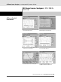
New Products, Agilent Open
DC Power Supply Selection Index
DC Power Supply Feature Description Index
3-4
5-11
12-15
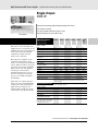
Basic DC Power Supplies…essential features for a tight budget
16
Single-Output: 30-60 W
Multiple-Output: 35 and 50 W
Triple-Output: 80 W GPIB
Single-Output: 120-200 W GPIB
Single & Dual Output: 30-100 W GPIB
Autoranging: 200-1000 W
Autoranging: 200-1000 W GPIB
Single Output: 750 W & 1500 W GPIB, LAN, USB
17-18
19
20
21-22
23-24
25-26
27-29
30-34
High Performance DC Power Supplies…speed and accuracy for test optimization 35
Single-Output: 40-500 W GPIB
Single-Output: 200-500 W
Single-Output: 2000-6600 W GPIB
Single-Output: 2000 W
Single-Output: 5000 W GPIB
Single-Output: 6600 W GPIB
Multiple-Output: 40-105 W GPIB
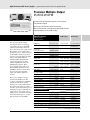
Precision Multiple-Output: 25-50 W GPIB
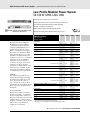
Low-Profile Modular Power System: 50-100 W GPIB, LAN, USB
Modular Power System: 1200 W per Mainframe GPIB
36-49
43-53
54-68
61-64
65-66
67-68
69-70
71-72
73-78
79-82
Application Specific DC Power Supplies…tailored solutions for specific needs
83
Mobile Communications DC Sources
Solar Array Simulators
Component Test DC Source
84-90
91-93
94-96
DC Electronic Loads…maximize throughput with real life loading conditions
97
Multiple-Input Electronic Loads
Single-Input Electronic Loads
98-104
105-108
AC Power Source/Analyzers….an integrated AC power solution
109
AC Power Source/Analyzers: 375-1750 VA
Power Products AC Line Voltage and Cord Options
Power Products Applications Information
Top 10 FAQs
AC Power and Load Connections
Power Product Terms
110-117
118-123
124
124-127
128-135
136-141
More detailed specifications at www.agilent.com/find/power
1
Table of Contents
(Continued)
Data Acquisition and Switching
142
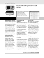
34970A Low-Cost Data Acqusition/Switch Unit
34980A Multifunction Switch/Measure Mainframe and Modules
143-148
149-156
Digital Multimeters, Voltmeters
157
34401A Digital Multimeter, 6 1/2 digits
3458A Digit Multimeter, 8 1/2 digits
158-161
162-164
34420A Nanovolt/Micro-ohm Meter
165-167
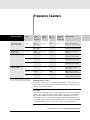
Frequency Counters
168
53131A Frequency Counter, Two Ch, 10, digit/s
53132A Frequency Counter, Two Ch, 12, digit/s
53181A Frequency Counter, Single Ch, 10, digit/s
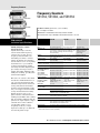
53140 Series Microwave Frequency Counter with Power Meter
53150 Series Microwave Frequency Counter
169-171
169-171
169-171
172-174
175-177
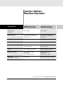
Function/Arbitrary Waveform Generators
178
33220A Function/Arbitrary Waveform Generator, 20 MHz
33250A Function/Arbitrary Waveform Generator, 80 MHz
179-181
182-184
VXI Instruments, 3499 Switch Solutions and Connectivity Products
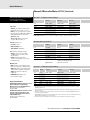
Model Number Index
Replacement Guide
185
186-187
188
More detailed specifications at www.agilent.com/find/power
2
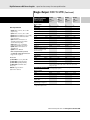
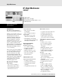
New
More
Products from Agilent
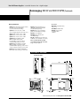
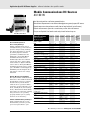
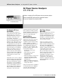
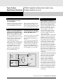
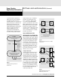
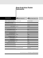
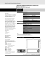
34980A Multifunction Switch/Measure Mainframe and Modules
Mix and match your switching with this compact and economical
34980A Multifunction Switch/Measure Unit for medium to
high-density switch/measure applications. The 34980A is an
8-slot modular mainframe with 19 plug-in modules in switching,
digital I/O, D/A converter, counter/totalizer functionality and
comes with open connectivity. See Page 149
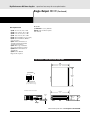
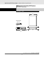
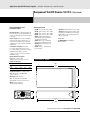
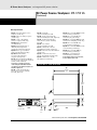
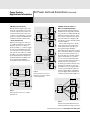
N5700 Series System DC Power Supplies
Get just the right performance at just the right price— in a
compact (1 U) package. These affordable 750 W and 1500 W single
output programmable DC power supplies with open connectivity
simplify system development and are ideal for simple DC power
applications. See Page 30
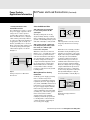
N6700 Low-Profile Modular Power System
The N6700 Modular Power System is small, flexible and fast.
Mix-and-match DC power modules optimize price and performance
to fit your needs and budget. With open connectivity, fast command
processing time, and four outputs in 1 U, the N6700 is ideal for
ATE and production test systems. See Page 73
Modification Service
While the products in this catalog are intended to satisfy a wide
range of customer applications, Agilent recognizes that these
products may not match all needs. To better meet your specific
requirements, Agilent offers a special modfication service. This service entails the design and manufacture of modified versions
of standard catalog models.
3
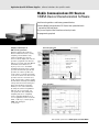
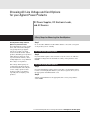
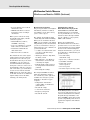
Tools to Make Your Test Development Process
as Easy as it is Successful
Agilent Open products are
the ones you use most, and
the ones you count on for
ongoing reliable results.
Agilent Open products have:
System-ready convenience
Selecting an Agilent instrument for your test is an easy
choice-because it makes system setup so easy for you.
Because our IO Libraries Suite software is included
with every Agilent Open instrument, you’ll get an error
free connection to your instruments every time. How?
Agilent’s connection Expert installs automatically,
configuring interfaces, discovering other instruments
(regardless of the manufacturer), and verifying their
connections. In less than 15 minutes (yes, minutes)and with just one reboot-your PC can be up, running,
and communicating with your instruments.
Standard PC I/O interfaces
It's hard to connect instruments to your system when
they don’t have the right interface. Agilent minimizes
the frustrations of mixed I/O interfaces by offering
GPIB, LAN and USB ports in Agilent Open instruments.
This gives you the flexibility to choose the interface
that works best with your system now- and use
another one in the future. No other test and measurement vendor supports more standard PC interfaces.
Visit www.agilent.com/find/open
for more information and
to see the latest tools and
The flexibility to program in any software environment.
Chances are, you’re an engineer, not a programmer.
So why spend time struggling with unfamiliar programming languages just to set up a test? Agilent Open
means you can work in the development environment
you’re already comfortable with-whatever that environment might be. The IO Libraries Suite connectivity
software easily transitions you to Excel or popular programming languages such as Visual Basic, C, LabVIEW,
Agilent VEE Pro, Visual Basic.NET, Visual C++, Visual C#
and others. So you can focus your efforts on the results
from your device, not the code that gets you there.
technologies
4
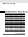
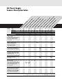
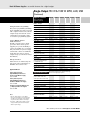
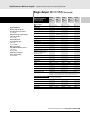
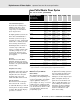
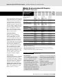
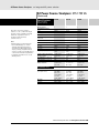
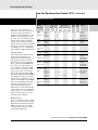
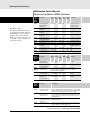
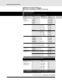
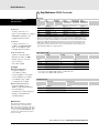
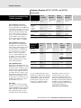
DC Power Supply Selection Index
Maximum
Volts
Maximum
Amps
Maximum
Watts
Number of
Outputs
GPIB
Model
Number
Type
3
300
900
1
*
6671A-J08
Performance
3.3
1000
3300
1
*
6680A-J04
Performance
65
5
10
50
up to 4
*
N6731B
Basic
75
5
20
100
up to 4
*
N6741B
Basic
77
5
875
4400
1
*
6680A
Performance
65
5.7
20
100
up to 8
*
66101A-J03
Performance
80
6
2.5
15
3
E3630A
Basic
19
*
Page
Number
55
6
5
30
3
E3631A
Basic
20
6
60
360
1
6551A-J03
Performance
51
6
60
360
1
6651A-J03
Performance
47
6
100
600
1
*
N5741A
Basic
31
6
180
1080
1
*
N5761A
Basic
33
6.7
30
200
1
*
6033A
Autoranging
27
7
0.015
0.11
2
*
6625A
Performance
71
7
0.015
0.11
4
*
6626A
Performance
71
7
5
35
3
*
6623A
Performance
69
7
5
35
4
*
6624A
Performance
69
7
10
70
2
*
6621A
Performance
69
7
10
70
3
*
6623A
Performance
69
7
120
840
1
6011A
Autoranging
25
7
120
1000
1
*
6031A
Autoranging
27
8
3
24
1
*
E3640A
Basic
23
8
3
24
2
*
E3646A
Basic
24
8
3
30
1
E3610A
Basic
17
8
5
40
1
*
6611C
Performance
36
8
5
40
1
*
E3642A
Basic
23
8
5
40
2
*
E3648A
Basic
24
8
6
48
1
E3614A
Basic
17
8
6.25
50
up to 4
*
N6732B
Basic
75
8
8
80
1
*
E3644A
Basic
23
8
10
80
1
*
6631B
Performance
38
8
12.5
100
up to 4
*
N6742B
Basic
77
More detailed specifications at www.agilent.com/find/power
5
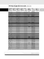
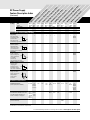
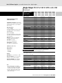
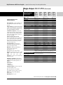
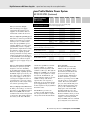
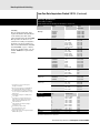
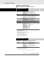
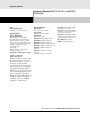
DC Power Supply Selection Index
Maximum
Volts
Maximum
Amps
Maximum
Watts
(Continued)
Number of
Outputs
GPIB
Model
Number
Type
Page
Number
*
66101A
Performance
79
6541A
Performance
43
8
16
128
up to 8
8
20
160
1
8
20
160
1
*
6641A
Performance
40
8
20
160
1
*
E3633A
Basic
21
8
50
400
1
6551A
Performance
50
8
50
400
1
*
6651A
Performance
46
8
90
720
1
*
N5742A
Basic
31
8
165
1320
1
*
N5762A
Basic
33
8
220
1760
1
6571A
Performance
61
8
220
1760
1
*
6671A
Performance
54
8
580
4600
1
*
6681A
Performance
65
10
5
50
1
*
6611C-J05
Performance
36
10
50
500
1
6551A-J01
Performance
51
10
50
500
1
6651A-J01
Performance
46
10
200
2000
1
6571A-J04
Performance
62
10
200
2000
1
*
6671A-J04
Performance
55
+/-10.25
+/-0.5125
5.5
4
*
N3280A
Component Test
94
12
1.5
18
2
*
66309B
Mobile
Communications
84
12
1.5
18
2
*
66309D
Mobile
Communications
84
12
1.5
18
2
*
66319B
Mobile
Communications
84
12
1.5
18
2
*
66319D
Mobile
Communications
84
12
12
150
up to 8
*
66101A-J05
Performance
80
12.5
60
750
1
*
N5743A
Basic
31
*
*
12.5
120
1500
1
N5763A
Basic
33
13
15.3
200
1
6541A-J04
Performance
44
14
150
2000
1
6571A-J03
Performance
61
14
150
2000
1
6671A-J03
Performance
55
15
2
30
1
E3610A
Basic
17
15
3
45
2
*
66309B
Mobile
Communications
84
15
3
45
2
*
66309D
Mobile
Communications
84
15
3
45
1
*
66311B
Mobile
Communications
84
15
3
45
1
*
66311D
Mobile
Communications
84
15
3
45
2
*
66319B
Mobile
Communications
84
15
3
45
2
*
66319D
Mobile
Communications
84
*
More detailed specifications at www.agilent.com/find/power
6
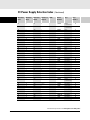
DC Power Supply Selection Index
(Continued)
Maximum
Volts
Maximum
Amps
Maximum
Watts
Number of
Outputs
GPIB
Model
Number
Type
Page
Number
15
3
45
2
*
66321B
Mobile
Communications
84
15
3
45
2
*
66321D
Mobile
Communications
84
15
7
105
1
*
E3632A
Basic
21
15
10
150
up to 8
*
66102A-J05
Performance
80
15
120
1800
1
6571A-J17
Performance
62
15
120
1800
1
*
6671A-J17
Performance
55
15
440
6600
1
*
6690A
Performance
67
16
0.2
3.2
2
*
6625A
Performance
71
16
0.2
3.2
4
*
6626A
Performance
71
16
0.2
3.2
2
*
6628A
Performance
71
16
0.2
3.2
4
*
6629A
Performance
71
17
30
510
1
*
6651A-J09
Performance
47
20
0.5
10
3
E3630A
Basic
19
20
1.5
30
1
E3611A
Basic
17
20
1.5
30
1
*
E3640A
Basic
23
20
1.5
30
2
*
E3646A
Basic
24
20
2
40
1
*
6612C
Performance
36
20
2
40
3
*
6623A
Performance
69
20
2
40
4
*
6624A
Performance
69
20
2
40
4
*
6627A
Performance
69
20
2.5
50
1
*
E3642A
Basic
23
20
2.5
50
2
*
E3648A
Basic
24
20
2.5
50
up to 4
*
N6733B
Basic
75
20
3
60
1
E3615A
Basic
18
20
4
80
2
*
6621A
Performance
69
20
4
80
2
*
6622A
Performance
69
20
4
80
3
*
6623A
Performance
69
20
4
80
1
*
E3644A
Basic
23
20
5
100
1
*
6632B
Performance
38
20
5
100
1
*
66332A
Mobile
Communications
84
77
20
5
100
up to 4
*
N6743B
Basic
20
7.5
150
up to 8
*
66102A
Performance
79
20
10
200
1
*
6033A
Autoranging
27
20
10
200
1
*
6038A
Autoranging
27
20
10
200
1
6542A
Performance
43
20
10
200
1
*
6642A
Performance
40
20
10
200
1
*
E3633A
Basic
21
20
15
300
1
*
6651A-J09
Performance
47
20
25
500
1
6552A
Performance
50
20
25
500
1
6652A
Performance
46
*
More detailed specifications at www.agilent.com/find/power
7
DC Power Supply Selection Index
Maximum
Volts
Maximum
Amps
20
20
(Continued)
Maximum
Watts
Number of
Outputs
GPIB
Model
Number
Type
Page
Number
38
760
1
*
N5744A
Basic
31
50
1000
1
6011A
Autoranging
25
20
50
1000
1
6012B
Autoranging
25
20
50
1000
1
*
6031A
Autoranging
27
20
50
1000
1
*
6032A
Autoranging
27
20
76
1520
1
*
N5764A
Basic
33
20
100
2000
1
6572A
Performance
61
20
100
2000
1
*
6672A
Performance
54
21
240
5000
1
*
6682A
Performance
65
24
6
100
up to 8
*
66103A-J12
Performance
81
24
85
2000
1
*
6672A-J04
Performance
55
25
1
25
2
E3620A
Basic
19
25
1
25
3
*
E3631A
Basic
20
25
7
160
1
*
E3634A
Basic
21
25
7
175
1
*
E3634A
Basic
21
27
20
540
1
*
6652A-J03
Performance
47
28
5
140
up to 8
*
66103A-J09
Performance
81
30
3.3
100
1
*
66332A-J01
Mobile
Communications
84
30
4
120
1
*
E3632A
Basic
21
30
17.5
500
1
*
6653A-J17
Performance
47
30
17.5
525
1
6553A-J17
Performance
51
30
25
750
1
*
N5745A
Basic
31
30
50
1500
1
*
N5765A
Basic
33
30
220
6600
1
*
6691A
Performance
67
32
160
5100
1
*
6683A
Performance
65
35
0.8
28
2
*
E3647A
Basic
24
35
0.8
30
1
*
E3641A
Basic
23
35
0.85
30
1
E3611A
Basic
17
35
1.25
40
up to 8
*
66105A-J01
Performance
81
35
1.4
49
2
*
E3649A
Basic
24
35
1.4
50
1
*
E3643A
Basic
23
35
1.5
50
up to 4
*
N6734B
Basic
75
35
1.7
60
1
E3616A
Basic
18
35
2.2
80
1
*
E3645A
Basic
24
35
3
80
3
*
6623A-J03
Performance
69
35
3
100
up to 4
*
N6744B
Basic
77
*
66103A
Performance
79
6543A
Performance
43
6643A
Performance
40
6553A
Performance
50
6653A
Performance
46
6573A
Performance
61
35
4.5
150
up to 8
35
6
210
1
35
6
210
1
35
15
525
1
35
15
525
1
35
60
2100
1
*
*
More detailed specifications at www.agilent.com/find/power
8
DC Power Supply Selection Index
Maximum
Volts
Maximum
Amps
Maximum
Watts
Number of
Outputs
(Continued)
GPIB
Model
Number
Type
Page
Number
35
60
2100
1
*
6673A
Performance
54
37
4
150
up to 8
*
66103A-J01
Performance
80
37.5
45
1690
1
6573A-J03
Performance
62
37.5
45
1690
1
*
6673A-J03
Performance
55
40
3.6
100
up to 8
*
66103A-J02
Performance
80
40
5
200
1
*
6643A-J11
Performance
41
40
12.5
500
1
6553A-J04
Performance
51
40
12.5
500
1
*
6653A-J04
Performance
47
40
19
760
1
*
N5746A
Basic
31
40
30
1200
1
6012B
Autoranging
25
40
38
1520
1
N5766A
Basic
33
40
50
2000
1
6573A-J08
Performance
62
40
50
2000
1
*
6673A-J08
Performance
56
40
128
5100
1
*
6684A
Performance
65
43.5
11
480
1
*
E4350B-J04
Solor Array
Simulator
92
50
0.5
25
2
*
6625A
Performance
71
50
0.5
25
4
*
6626A
Performance
71
50
0.8
40
3
*
6623A
Performance
69
50
0.8
40
4
*
6624A
Performance
69
50
0.8
40
4
*
6627A
Performance
69
50
1
50
1
*
6613C
Performance
36
50
1
50
2
*
6625A
Performance
71
50
1
50
4
*
6626A
Performance
71
50
1
50
2
*
6628A
Performance
71
50
1
50
4
*
6629A
Performance
71
50
1.5
50
up to 4
*
N6761A
Performance
73
50
2
80
2
*
6622A
Performance
69
50
2
100
1
*
6633B
Performance
38
50
3
100
up to 4
*
N6762A
Performance
73
50
4
200
1
*
E3634A
Basic
21
*
50
5
50
up to 4
*
N6751A
Performance
73
50
10
500
1
*
6554A-J05
Performance
51
50
10
500
1
6654A-J05
Performance
48
50
10
100
up to 4
*
N6752A
Performance
73
50
42
2000
1
*
6574A-J07
Performance
62
50
42
2000
1
*
6674A-J07
Performance
56
51.8
10
518
1
*
E4350B-J03
Solar Array
Simulator
92
54
9.6
480
1
*
E4350B-J01
Solar Array
Simulator
91
55
3
165
1
*
66104A-J09
Performance
81
56
38
2000
1
6574A-J03
Performance
62
More detailed specifications at www.agilent.com/find/power
9
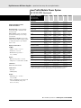
DC Power Supply Selection Index
Maximum
Volts
Maximum
Amps
Maximum
Watts
56
38
60
0.5
60
60
(Continued)
Number of
Outputs
GPIB
Model
Number
Type
2000
1
*
6674A-J03
Performance
56
30
1
E3612A
Basic
17
0.5
30
1
*
E3641A
Basic
23
0.5
30
2
*
E3647A
Basic
24
60
0.8
48
2
*
E3649A
Basic
24
60
0.8
50
1
*
E3643A
Basic
23
60
0.8
50
up to 4
*
N6735B
Basic
75
60
1
60
1
E3617A
Basic
18
60
1.3
80
1
*
E3645A
Basic
24
60
1.6
100
up to 4
*
N6745B
Basic
77
60
2.5
150
up to 8
*
66104A
Performance
79
60
3.3
200
1
*
6038A
Autoranging
27
60
3.5
210
1
6544A
Performance
43
60
3.5
210
1
6644A
Performance
40
60
9
540
1
6554A
Performance
50
60
9
540
1
*
6654A
Performance
46
60
12.5
750
1
*
N5747A
Basic
32
60
17
1020
1
6010A
Autoranging
25
60
17
1200
1
6030A
Autoranging
27
60
17.5
1050
1
6012B
Autoranging
25
60
17.5
1200
1
*
6032A
Autoranging
27
60
25
1500
1
*
N5767A
Basic
34
60
35
2100
1
6574A
Performance
61
60
35
2100
1
*
6674A
Performance
54
60
110
6600
1
*
6692A
Performance
67
65
8
480
1
*
E4350B
Solar Array
Simulator
91
68
7
480
1
*
E4350B-J06
Solar Array
Simulator
92
70
3
200
1
*
6644A-J09
Performance
41
70
3
200
1
*
6544A-J09
Performance
44
70
7.5
500
1
6554A-J04
Performance
51
70
7.5
500
1
6654A-J04
Performance
48
80
6
480
1
6554A-J12
Performance
52
80
6
500
1
*
6654A-J12
Performance
48
80
9.5
760
1
*
N5748A
Basic
32
80
19
1520
1
*
N5768A
Basic
34
86
6
516
1
*
E4350B-J02
Solar Array
Simulator
91
*
*
*
Page
Number
100
0.5
50
1
*
6614C
Performance
36
100
0.5
50
up to 4
*
N6736B
Basic
75
100
1
100
1
*
6634B
Performance
38
100
1
100
up to 4
*
N6746B
Basic
77
More detailed specifications at www.agilent.com/find/power
10
DC Power Supply Selection Index
(Continued)
Maximum
Volts
Maximum
Amps
Maximum
Watts
Number of
Outputs
GPIB
Model
Number
Type
Page
Number
100
7.5
750
1
*
N5749A
Basic
32
100
15
1500
1
*
N5769A
Basic
34
100
22
2000
1
6575A-J08
Performance
63
100
22
2000
1
6675A-J08
Performance
57
110
20
2000
1
6575A-J09
Performance
63
110
20
2000
1
6675A-J09
Performance
57
120
0.25
30
1
E3612A
Basic
17
66105A
Performance
79
6545A
Performance
43
6645A
Performance
40
6555A
Performance
50
6655A
Performance
46
6575A
Performance
61
*
*
120
1.25
150
up to 8
120
1.5
180
1
*
120
1.5
180
1
120
4.5
540
1
120
4
540
1
120
18
2160
1
120
18
2160
1
*
6675A
Performance
54
130
4
480
1
*
E4351B
Solar Array
Simulator
91
135
16
2000
1
6575A-J06
Performance
63
135
16
2000
1
6675A-J06
Performance
56
150
1.2
150
1
6545A-J05
Performance
44
150
1.2
150
1
*
6645A-J05
Performance
41
150
3.2
500
1
*
6655A-J05
Performance
48
150
5
750
1
*
N5750A
Basic
32
*
*
*
150
10
1500
1
*
N5770A
Basic
34
150
15
2000
1
*
6675A-J11
Performance
57
150
15
2250
1
6575A-J11
Performance
63
156
3
500
1
6555A-J10
Performance
52
156
3
500
1
6655A-J10
Performance
48
160
13
2000
1
6575A-J04
Performance
63
160
13
2000
1
*
6675A-J04
Performance
54
170
1
170
1
*
6645A-J06
Performance
41
200
0.75
150
up to 8
*
66106A
Performance
79
200
5
1000
1
6010A
Autoranging
25
200
5
1000
1
6015A
Autoranging
25
200
5
1000
1
*
6035A
Autoranging
27
200
5
1200
1
*
6030A
Autoranging
27
200
11
2000
1
6575A-J07
Performance
63
300
2.5
750
1
*
N5751A
Basic
32
*
N5771A
Basic
34
6015A
Autoranging
25
*
300
5
1500
1
500
2
1000
1
500
2
1000
1
*
6035A
Autoranging
27
600
1.3
780
1
*
N5752A
Basic
32
600
2.6
1560
1
*
N5772A
Basic
34
More detailed specifications at www.agilent.com/find/power
11
30 W 200 W
Max Voltage
500 V
100 V
50 V
50 V
120 V
120 V
200 V
20 V
Max Current
120 A
10 A
10 A
2A
50 A
875 A
16 A
5A
Page
27
36
69
71
40
54
79
84
19
Ou
pu
ut
ut
tp
le
Ou
tip
e-
ul
gl
M
n
in
io
N5
N6
70
70
0S
0S
er
er
ie
ie
s
sS
is
Pr
0A
28
N3
t
le-O
ul
M
&
le
ng
ec
0S
64
E3
0&
63
E3
200 W - 40 W 1000 W 100 W
Si
ies
er
ob
M
s
ie
er
0S
30
66
Max
Power
tip
at
ic
m
m
ile
Co
Sy
er
w
Po
ar
ul
od
M
0
00
66
40 W100 W
un
em
st
ut
-O
le
ng
Si
s
69
-6
70
66
200 W - 2000 W - 1200 W
500 W 6600 W
s
pu
t
pu
-O
le
ie
er
0S
50
66
&
40
66
ut
le
ng
Si
s
rie
Se
ec
Pr
s
rie
Se
20
66
ul
M
n
io
is
tip
ul
M
s
rie
Se
20
66
tip
t
pu
ut
-O
le
Si
s
rie
Se
30
66
&
25 W &
50 W
t
ut
-O
t
pu
ut
-O
le
ng
s
er
ng
ra
to
Au
s
rie
Se
10
40 W &
80 W
66
30
60
DC Range
io
pu
ns
t
tp
ut
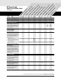
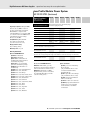
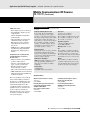
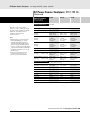
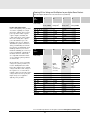
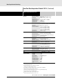
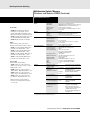
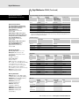
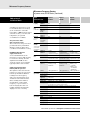
DC Power Supply
Feature Description Index
5W
700 W
1500 W
50 W
100W
60 V
10 V
600 V
100 V
20 A
0.5 A
180 A
20 A
94
31
73
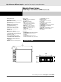
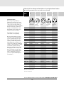
Configuration Features
•
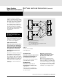
“One-box” solution
To preserve rack space and interconnections,
the voltage and current programmers,
current shunt, and DVM are built-in
to one package.
•
•
•
•
•
•
•
•
•
•
Modular power system
(multiple reconfigurable outputs)
Modules can be installed into a
mainframe, and configuration
can be changed at any time.
•
•
•
•
•
•
Analog programming and monitoring ports
Analog programming ports allow the power
supply to be used as a power amplifier,
responding to an external voltage signal.
Monitoring ports allow an external DMM
to monitor the power-supply outputs.
• •
S
AP
S
S
P
P
up to 2 up to 2
identical identical
outputs outputs
S
AP
S
AP
•
•
•
•
•
•
Auto-parallel, auto-series, parallel,
and series operation
When connected in auto-parallel or autoseries, only one unit has to be programmed
to take advantage of the full power from all.
AP=auto-parallel AS=auto-series
S=series P=parallel
Up to 4
66309
B/D
66319
B/D
•
Serial link
Up to 16 power supply outputs can share
one GPIB address when connected with
a telephone style cable.
•
•
Up to 8
Multiple non-reconfigurable outputs
Up to four outputs are included in one
package, and they share one GPIB address.
Relay connect, disconnect, & polarity reversal
Optionally integrated with the
power supply
•
S, P
•
•
66332A
Only
Disconnect
only
S, P
•
•
•
For more detailed specifications see the product manual at www.agilent.com/find/power
12
ut
tp
Ou
tp
Ou
egl
in
ie
s
sS
er
ie
0S
er
70
0S
N6
70
N5
700 W
1500 W
ut
-O
ul
M
n
io
is
ec
Pr
0A
28
N3
t
ut
tip
tip
&
le
ng
Si
ies
er
0S
64
E3
0&
63
E3
5W
le
M
un
m
m
Co
ile
ob
M
s
ie
er
0S
30
66
30 W 200 W
ul
s
em
st
Sy
er
w
Po
ar
ul
od
M
0
00
ic
t
pu
ut
-O
le
ng
Si
s
ie
er
66
40 W100 W
pu
io
at
t
pu
ut
-O
le
ng
Si
0S
69
-6
70
66
40
66
200 W - 2000 W - 1200 W
500 W 6600 W
le-
ns
t
pu
ut
le
ul
s
rie
50
66
&
Se
66
Se
ec
Pr
s
rie
s
rie
20
Se
20
66
25 W &
50 W
tip
t
n
io
is
tip
ul
M
Se
30
66
&
M
ut
-O
le
Si
s
rie
to
Au
s
rie
Se
10
40 W &
80 W
66
30
60
pu
-O
le
ng
s
er
ng
ra
(Continued)
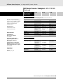
DC Range
-O
t
pu
ut
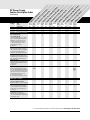
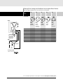
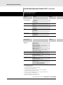
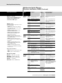
DC Power Supply
Feature Description Index
Max
Power
200 W - 40 W 1000 W 100 W
50 W
100 W
Max Voltage
500 V
100 V
50 V
50 V
120 V
120 V
200 V
20 V
60 V
10 V
600 V
100 V
Max Current
120 A
10 A
10 A
2A
50 A
875 A
16 A
5A
20 A
0.5 A
180 A
20 A
Page
27
36
69
71
40
54
79
84
19
94
31
73
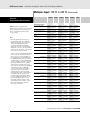
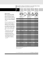
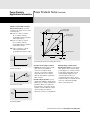
Output Voltage and Current Range Changing
Single Range
The output voltage
v
is limited by a single
maximum value.
The output current
is limited by a single maximum value.
Single Range + Peak Current Pulse
A limited amplitude
and limited width
v
current pulse can be
sourced beyond the
maximum static current limit.
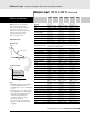
Autoranging
A wide, continuous
range of voltage and
v
current combinations
are available
automatically
at the maximum power level.
Multiple-output range changing
Automatic range
changing gives
maximum power to
v
two different voltage
and current combinations.
•
•
•
•
•
•
N6730
N6740
l
•
l
•
•
N6750
N6760
l
•
•
•
l
•
Precision multiple-output range changing
Voltage and current
ranges can be chosen
independently to
v
provide greater
l
resolution.
•
N6760
Performance Characteristics
Output ripple and noise
(Peak-to-peak, 20 Hz to 20 MHz)
30 - 160 mV
Output programming response time
Rise and fall time with full resistive load
(10 to 90% and 90 to 10%) Does not
include command processing time.
200 W:
•(100
ms -
Programming resolution
(percent of full scale)
3 mV
(10 mV to
25 mV in
fast mode)
3 mV
3 mV
3 mV7 mV
7 mV25 mV
5-50 mV
3-10 mV
2-8 mV
4 mV
60300 mV
6 mV
N6750
N6760
10-30 mV
N6730
N6740
2 ms
(0.4 ms
200 ms) in fast
1000 W: mode)
(300 ms 2000 ms)
2-6 ms
6 ms
15 ms
9 ms195 ms
20 ms50 ms
0.4 ms2 ms
60 ms
150 µs
0.08 s
to 0.30 s
*
• 0.025%
0.03%
0.007%
0.025%
0.025%
0.03%
0.025% 0.025%/ 0.003%
0.007%
*
*
0.025%
*See Datasheet or User’s Guide for complete details
For more detailed specifications see the product manual at www.agilent.com/find/power
13
ut
tp
Ou
t
ut
tip
ut
-O
N5
tp
s
ie
N6
70
70
0S
0S
er
er
ie
ec
sS
is
in
io
n
gl
M
e-
ul
Ou
tip
&
le
ng
Si
ies
er
Pr
0A
28
N3
5W
le
M
un
m
m
0S
64
E3
0&
63
E3
66
Co
ile
ob
M
s
ie
er
0S
30
30 W 200 W
ul
s
em
st
Sy
er
w
Po
ar
ul
od
M
ic
t
pu
ut
-O
le
ng
Si
s
ie
0
00
66
200 W - 2000 W - 1200 W 40 W500 W 6600 W
100 W
pu
io
at
t
pu
ut
-O
le
er
0S
69
-6
70
66
40
66
le-
ns
t
pu
ut
le
tip
Si
s
rie
Se
50
66
&
Se
66
ng
M
n
io
is
ec
Pr
s
rie
s
rie
20
Se
20
66
40 W & 25 W &
80 W
50 W
ul
pu
ut
tip
ul
M
Se
30
66
&
10
-O
le
Si
s
rie
to
Au
s
rie
Se
66
30
60
t
ut
-O
le
ng
s
er
ng
ra
(Continued)
DC Range
-O
t
pu
DC Power Supply
Feature Description Index
Max
Power
200 W - 40 W 1000 W 100 W
700 W 50 W
1500 W 100 W
Max Voltage
500 V
100 V
50 V
50 V
120 V
120 V
200 V
20 V
60 V
10 V
600 V
100 V
Max Current
120 A
10 A
10 A
2A
50 A
875 A
16 A
5A
20 A
0.5 A
180 A
20 A
Page
00
00, 00
00
00
00, 00
00, 00, 00
00
00
00, 00
00
00
00
GPIB Programming Features
GPIB programming of voltage and current
Self-documenting programming commands
mean that programming is done in units
of volts and amps, not in percentages or
binary representations.
•
•
•
•
•
•
•
•
•
•
Measured voltage and current
read-back over the GPIB
The output is read back in
units of volts and amps.
•
•
•
•
•
•
•
•
•
0
4
0
4
5
6670-5
6680-4
6690-4
5
4
16/5
0
10
7
0
0
5
•
•
•
•
GPIB programmable overvoltage protection
Can be enabled to quickly down-program
the output and set SRQ and/or DFI/RI.
T = Can generate trigger.
M = Overvoltage, the level is set manually
with a front-panel control.
M
•
T
T
•
GPIB programmable overcurrent protection
Can be enabled to quickly down-program
the output and set SRQ and/or DFI/RI.
T = Can generate trigger.
•
•
•
•
Overtemperature protection
Will down-program the output and can
be enabled to set SRQ and/or DFI.
T = Can generate trigger.
•
•
•
•
Store-recall states
Complete operating states can be stored
in nonvolatile memory. Each state specifies
not only the output voltage and current,
but also many of the programmable
protection features.
Number nonvolatile states
Standard Commands for Programmable
Instruments (SCPI)
SCPI is the standard language for test and
measurement equipment. Standard codes
make a software writing and maintenance
more efficient. For example, using this
standard, the output voltage of the power
supply is measured with the same command
(MEASURE: VOLTAGE?) by either a DMM
or a power supply.
Protection Features
•
GPIB
LAN
USB
•
•
•
5
0
1
2
0
0
0
0
0
•
•
•
•
•
•
•
T
•
•
•
T
M
T
•
•
T
•
E3630
only
•
T
T
•
•
T
•
•
T
T
•
(One of these states is automatically
accessed on turn-on)
Number volatile states
•
GPIB
LAN
USB
•
For more detailed specifications see the product manual at www.agilent.com/find/power
14
ut
tp
Ou
t
ut
tip
ut
-O
N5
tp
s
ie
N6
70
70
0S
0S
er
er
ie
ec
sS
is
in
io
n
gl
M
e-
ul
Ou
tip
&
le
ng
Si
ies
er
Pr
0A
28
N3
5W
le
M
un
m
m
0S
64
E3
0&
63
E3
66
Co
ile
ob
M
s
ie
er
0S
30
30 W 200 W
ul
s
em
st
Sy
er
w
Po
ar
ul
od
M
ic
t
pu
ut
-O
le
ng
Si
s
ie
0
00
66
200 W - 2000 W - 1200 W 40 W500 W 6600 W
100 W
pu
io
at
t
pu
ut
-O
le
er
0S
69
-6
70
66
40
66
le-
ns
t
pu
ut
le
tip
Si
s
rie
Se
50
66
&
Se
66
ng
M
n
io
is
ec
Pr
s
rie
s
rie
20
Se
20
66
40 W & 25 W &
80 W
50 W
ul
pu
ut
tip
ul
M
Se
30
66
&
10
-O
le
Si
s
rie
to
Au
s
rie
Se
66
30
60
t
ut
-O
le
ng
s
er
ng
ra
(Continued)
DC Range
-O
t
pu
DC Power Supply
Feature Description Index
Max
Power
200 W - 40 W 1000 W 100 W
700 W- 50 W1500 W 100 W
Max Voltage
500 V
100 V
50 V
50 V
120 V
120 V
200 V
20 V
60 V
10 V
600 V
100 V
Max Current
120 A
10 A
10 A
2A
50 A
875 A
16 A
5A
20 A
0.5 A
180 A
20 A
Page
00
00, 00
00
00
00, 00
00, 00, 00
00
00
00, 00
00
00
00
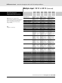
Protection Features (Continued)
Discrete fault indicator/
remote inhibit (DFI/RI)
Using these digital ports, power supplies
can be connected independently of the
GPIB. If any one experiences an error
condition (overvoltage, for example),
it can signal the other units to also
downprogram their outputs.
O = Optional
•
•
O
O
•
•
•
•
SRQ
Almost any fault condition or change of
state of the power supply can be enabled
to generate an SRQ. This signals the
computer to take the appropriate action.
•
•
•
•
•
•
•
•
Local lockout
Front-panel or keyboard control can be
disabled. This keeps unauthorized operators
from changing the programmed states.
•
•
•
•
•
•
•
•
•
•
•
•
•
Fan-speed control
Controls the fan-speed to provide only the
required cooling, reducing unnecessary
acoustic noise.
O = Optional
Active down-programming
Active circuits quickly drain the energy
from the output when unit is programmed
to a lower voltage. This means that a unit
under test can be safely removed from its
test fixture without danger of arcing.
F = Full-rated output current
P = Less than 100% rated output current
Maintenance Features
•
P
•
•
•
•
•
•
•
•
•
•
•
6610-P
6630-F
F
F
P
P
P
P
P
N6750
N6760
only
•
•
•
•
•
•
•
•
•
•
•
P, S
J
J
P, J
P, J
P, S
P, S
P, J
P
*P
*P
•
•
•
•
•
•
•
•
•
•
•
•
Electronic calibration in the rack
Calibration requires no internal adjustments.
Calibration security
Units can be protected from accidental
access to calibration routines by either a
password (P) or an internal jumper (J )
or switch (s).
Self-test
Extensive self-test is triggered
automatically on power-up. Additional
tests can be initialed by user programming
or front-panel control.
•
•
*A nonvolatile status in SCPI mode only.
For more detailed specifications see the product manual at www.agilent.com/find/power
15
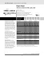
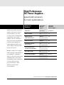
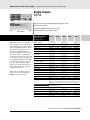
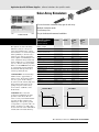
Basic DC Power Supplies...
essential features
for a tight budget
Comparison
Summary
Agilent Basic
DC Power
Supplies
Agilent High
Performance
DC Power Supplies
Output Power
30 W-1500 W
40 W-6,600 W
Number of outputs
1-3
1-8
GPIB programming and
measurement speed
Moderate
Fast
Output rise/fall time
Moderate
Fast
Convenient 1/2 rack-size
for bench-top use
Yes
No
level of capability.
Active Downprogrammer
for enhanced test throughput
No
Yes
If you do not need the
Stored wake-up state
No
Yes
Programmable Capabilities
Moderate
Extensive
Protection for the DUT
Moderate
Extensive
Agilent Basic DC Power
Supplies are the right choice
for many applications. They
provide quiet, stable DC power
for both manual and automatic
testing, in R&D and in manufacturing environments, where
speed and accuracy are low
considerations. At their price
level, they have a surprising
performance level and features
of Agilent High Performance DC
Power Supplies, then choose
Agilent Basic DC Power Supplies.
This summary table will help
you decide which family of
DC power supplies best meets
your needs.
More detailed specifications at www.agilent.com/find/power
16
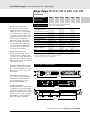
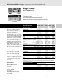
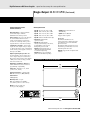
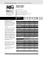
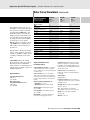
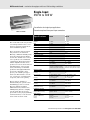
Basic DC Power Supplies essential features for a tight budget
Single-Output
30-60 W
E3610A-E3617A
Small, compact size for bench use
Low-noise and excellent regulation
Dual-range outputs (E3610A/11A/12A)
Specifications
E3610A
E3611A
E3612A
E3614A
Number of output ranges
2
2
2
1
GPIB
No
No
No
No
Range 1
0 to 8 V,
0 to 3 A1
0 to 20 V,
0 to 1.5 A1
0 to 60 V,
0 to 0.5 A1
0 to 8 V,
0 to 6 A
Range 2
0 to 15 V,
0 to 2 A1
0 to 35 V,
0 to 0.85 A1
0 to 120 V,
0 to 0.25 A1
—
(at 0˚ to 55˚ C unless
otherwise specified)
These linear-regulated DC power
supplies provide reliable and convenient DC power on a lab bench. The
10-turn pots and clear voltage and
current meters allow fine adjustments to be made easily. These
models are CV/CC, so they can
serve as either voltage or current
sources. The “CC Set” button allows
the current setting to be viewed,
allowing easy adjustment of a
current limit. Either the positive or
negative terminal may be connected
to ground, creating a positive or
negative voltage, or floated up to
240 V from ground.
E3610A, E3611A, E3612A
These flexible 30 watt DC power
supplies have 2 ranges, providing
more current at lower voltage levels.
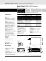
E3614A, E3615A, E3616A, E3617A
These DC power supplies provide
remote sensing to eliminate the
errors in voltage regulation due
to voltage drops in the load leads.
Delicate loads are protected by
the overvoltage protection feature.
Remote voltage signals can be used
to control the power supply’s output
voltage and current levels.
Output ratings1
Power (max)
30 W
30 W
30 W
48 W
Load and line regulation
0.01% + 2 mV
0.01% + 2 mV
0.01% + 2 mV
0.01% + 2 mV
Ripple and noise
from 20 Hz to 20 MHz
Voltage rms
200 µV
200 µV
200 µV
200 µV
peak-peak
2 mV
2 mV
2 mV
1 mV
Supplemental Characteristics
(Non-warranted characteristics determined by design and
useful in applying the product)
Control mode
CV/CC
CV/CC
CV/CC
Meter resolution
Voltage
10 mV
100 mV
100 mV
10 mV
(minimum change
using front-panel
controls)
Current
10 mA
10 mA
1 mA
10 mA
1
CV/CC
For 0ff-the-shelf shipment
Maximum current is derated 1% per °C between 40° to 55°C.
Application Notes:
Understanding Linear Power
Supply Operation (AN1554)
5989-2291EN
10 Practical Tips You Need
to Know About Your Power Products
5965-8239E
More detailed specifications at www.agilent.com/find/E3600
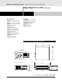
17
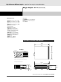
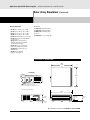
Basic DC Power Supplies essential features for a tight budget
Single-Output: 30-60 W (Continued)
Specifications
E3615A
E3616A
E3617A
Number of output ranges
1
1
1
GPIB
No
No
No
Range 1
0 to 20 V, 0 to 3 A
0 to 35 V, 0 to 1.7 A
0 to 60 V, 0 to 1 A
Range 2
—
—
—
Power (max)
60 W
60 W
60 W
Load and line regulation
0.01% + 2 mV
0.01% + 2 mV
0.01% + 2 mV
(at 0˚ to 55˚ C unless
otherwise specified)
Supplemental Characteristics
for all model numbers
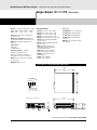
Size: E3610A-E3612A: 91 mm H x
213 mm W x 319 mm D (3.6 in x 8.4 in x
12.6 in); E3614A-E3617A: 91 mm H x
213 mm W x 373 mm D (3.6 in x 8.4 in x
14.7 in)
Weight: E3610A-E3612A: 3.8 kg (8.4 lb)
net, 5.1 kg (11.3 lb) shipping;
E3614A-E3617A: 5.5 kg (12.1 lb) net,
6.75 kg (14.9 lb) shipping
Output ratings1
Ripple and noise
from 20 Hz to 20 MHz
Voltage rms
200 µV
200 µV
200 µV
peak-peak
1 mV
1 mV
1 mV
Supplemental Characteristics
(Non-warranted characteristics determined by design and
useful in applying the product)
Warranty: One year
Control mode
CV/CC
CV/CC
CV/CC
Ordering Information
Meter resolution
Voltage
10 mV (0-20 V),
100 mV (>20 V)
10 mV (0-20 V),
100 mV (>20 V)
10 mV (0-20 V),
100 mV (>20 V)
Opt 0E9 90 to 110 Vac, 47 to 63 Hz
(Japan only)
Opt 0EM 104 to 126 Vac, 47 to 63 Hz
Opt 0E3 207 to 253 Vac, 47 to 63 Hz
Opt 1CM rack mount kit
(E3614A-E3617A only)
Opt 0L2 extra documentation package
(minimum change
using front-panel
controls)
Current
10 mA
1 mA
1 mA
1
For 0ff-the-shelf shipment
Maximum current is derated 1% per °C between 40° to 55°C.
More detailed specifications at www.agilent.com/find/E3600
18
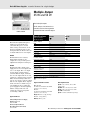
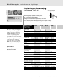
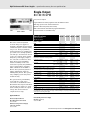
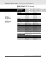
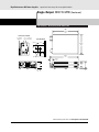
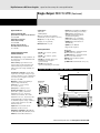
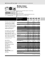
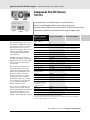
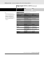
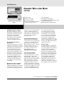
Basic DC Power Supplies essential features for a tight budget
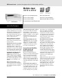
Multiple-Output
35 W and 50 W
E3620A, E3630A
Dual and triple outputs
Small, compact size for bench use
Low-noise and excellent regulation
Overload indicator to monitor output
Specifications
E3620A
E3630A
Number of Outputs
2
3
GPIB
No
No
Output 1
0 to 25 V, 0 to 1 A
0 to 6 V, 0 to 2.5 A*
Output 2
0 to 25 V, 0 to 1 A
0 to +20 V, 0 to 0.5 A
Output 3
—
0 to -20 V, 0 to 0.5 A
(at 0˚ to 55˚ C unless
otherwise specified)
These linear-regulated DC power
supplies provide reliable and
convenient DC power on a lab
bench. Voltage and current can be
monitored simultaneously on the
front panel meters. There is also an
overload indicator for each output.
E3620A
The E3620A has two isolated,
independent, CV/CL 25 volt
outputs. It is easy to make precise
adjustments using the 10-turn pots.
E3630A
The E3630A triple output power
supply has two 20 volt outputs and
one 6 volt output. The +6V output
is an isolated constant-voltage/
current-foldback output, and both
the +20 volt output and the -20 volt
output are constant-voltage/currentlimit. An autotracking feature lets
you use one voltage control to adjust
both 20 volt outputs. These outputs
track each other to within one percent, making it easy to adjust the
power supply for circuits requiring
balance voltages. The ±20 volt
outputs are referenced together
to a floating common.
Application Notes:
Understanding Linear Power Supply
Operation (AN1554)
5989-2291EN
Output ratings*
Power (max)
50 W
35 W
Load regulation
0.01% + 2mV
0.01% + 2mV
Normal mode voltage rms
350 µV
350 µV
peak-to-peak
1.5 mV
1.5 mV
Common mode current
1 µArms
1 µArms
Control mode
CV/CL
CV/CL (±20 V), CV/CL (6 V)
Voltage
10 mV (0-20 V), 100 mV, (>20 V)
10 mV
Current
1 mA
10 mA
Input power
115 Vac ± 10%, 47 to 63 Hz
115 Vac, ± 10%, 47 to 63 Hz
Ripple and noise
from 20 Hz to 20 MHz
Meter resolution
(Minimum change using
front-panel controls)
*Maximum current is derated 3.3% per °C from 40°C to 55°C
For off-the-shelf shipment
Supplemental Characteristics
Ordering Information
Size: E3620A:
213 mm W x 91 mm H x 401 mm D
(8.4 in x 3.6 in x 15.8 in)
E3630A:
213 mm W x 92 mm H x 320 mm D
(8.4 in x 3.6 in x 12.6 in)
Opt 0E9 90 to 110 Vac, 47 to 63 Hz
(Japan only)
Opt 0EM 104 to 126 Vac, 47 to 63 Hz
Opt 0E3 207 to 253 Vac, 47 to 63 Hz
Opt 1CM rack mount kit
Opt 0L2 extra documentation package
Weight: E3620A: 5.5 kg (12.1 lbs)
E3630A: 3.8 kg (8.4 lbs)
Warranty: Three years
10 Practical Tips You Need to
Know About Your Power Products
5965-8239E
More detailed specifications at www.agilent.com/find/E3600
19
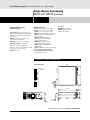
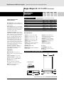
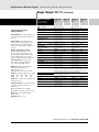
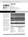
Basic DC Power Supplies essential features for a tight budget
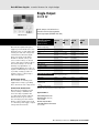
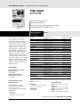
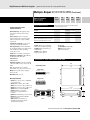
Triple-Output
80 W GPIB
E3631A
Small, compact size for bench use
Low output ripple and noise
Built-in measurements and basic programmable features
Over-voltage protection to ensure DUT safety
Specifications
E3631A
(at 0˚ to 55˚ C unless
otherwise specified)
This is the DC power supply for
every engineer’s or electronic
technician’s lab bench. It has two
tracking 25 V outputs, which are
together referenced to a floating
common, and an isolated 6 volt
output. It is easy to control from
the front panel, or with industry
standard SCPI commands via the
GPIB or RS232. VXIPlug&Play
drivers are available to further
simplify computer control. Up to
3 complete states can be stored for
later recall. The low noise, excellent
regulation, and built-in voltmeter/
ammeter make this reliable power
supply well suited for the needs
of the R&D lab.
DC outputs
Voltage
0 to +25 V
0 to -25 V
0 to 6 V
Current
0 to 1 A
0 to 1 A
0 to 5 A
Voltage
<0.01% + 2 mV
<0.01% + 2 mV
<0.01% + 2 mV
Current
<0.01% + 250 µA
<0.01% + 250 µA
<0.01% + 250 µA
Voltage
<0.01% + 2 mV
<0.01% + 2 mV
<0.01% + 2 mV
Current
<0.01% + 250 µA
<0.01% + 250 µA
<0.01% + 250 µA
Normal-mode voltage
<350 µV rms/2 mV p-p
<350 µV rms/2 mV p-p
<350 µV rms/2 mV p-p
Normal-mode current
<500 µA rms
<500 µA rms
<2 mA rms
Common-mode current
<1.5 µA rms
<1.5 µA rms
<1.5 µA rms
Load regulation
Line regulation
Ripple and noise
from 20 Hz to 20 MHz
Programming accuracy
at 25˚C ±5˚C
Voltage
0.05% + 20 mV
0.05% + 20 mV
0.1% + 5 mV
Current
0.15% + 4 mA
0.15% + 4 mA
0.2% + 10 mA
Voltage
0.05% + 10 mV
0.05% + 10 mV
0.1% + 5 mV
Current
0.15% + 4 mA
0.15% + 4 mA
0.2% + 10 mA
Program/readback
1.5 mV, 0.1 mA
1.5 mV, 0.1 mA
0.5 mV, 0.5 mA
Meter
10 mV, 1 mA
10 mV, 1 mA
1 mV, 1 mA
Transient response
50 µsec for output to recover to within 15 mV following a change in output
current from full load to half load or vice versa
Readback accuracy at 25˚C ±5˚C
Application Notes:
Understanding Linear Power Supply
Operation (AN1554)
5989-2291EN
10 Practical Tips You Need to
Know About Your Power Products
5965-8239E
Resolution
For off-the-shelf shipment
Supplemental Characteristics
for all model numbers
Product Regulation: Designed to
comply with UL1244, IEC 1010-1;
certified with CSA 22.2
Meets requirements for CE regulation
Software Driver:
• IVI-COM
• VXIPlug&Play
• IntuiLink Connectivity Software
Warranty: One year
Ordering Information
Size: E3631A
213 mm W x 133 mm H x 348 mm D
(8.4 in. x 5.2 in. x 14.2 in.)
Weight: E3631A
8.2 kg (18 lbs)
Opt 0E9 90 to 110 Vac, 47 to 63 Hz
(Japan only)
Opt 0EM 104 to 126 Vac, 47 to 63 Hz
Opt 0E3 207 to 253 Vac, 47 to 63 Hz
Opt 1CM rack mount kit
Opt 0L2 extra documentation package
More detailed specifications at www.agilent.com/find/E3600
20
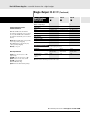
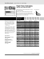
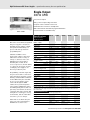
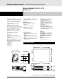
Basic DC Power Supplies essential features for a tight budget
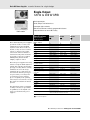
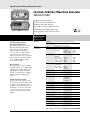
Single-Output
120 W to 200 W GPIB
E3632A-E3634A
Dual range outputs
Small, compact size for bench use
Low output ripple and noise
Built-in measurements and basic programmable features
Protection features to ensure DUT safety
Specifications
E3632A
E3633A
E3634A
(at 0˚ to 55˚ C unless
otherwise specified)
These dual range DC power supplies
provide the stable, accurate, and
reliable DC power that the R&D
engineer needs. These models are
CV/CC, so they can serve as either
voltage or current sources. They
can be used either for manual or
automated testing where moderate
speed and accuracy are required.
VXIPlug&Play drivers further
simplify computer control.
Number of Outputs
1
1
1
GPIB
Yes
Yes
Yes
Range 1
0 to 15 V, 7 A
0 to 8 V, 20 A
0 to 25 V, 7 A
Range 2
0 to 30 V, 4 A
0 to 20 V, 10 A
0 to 50 V, 4 A
Voltage
<0.01% + 2 mV
<0.01% + 2 mV
<0.01% + 2 mV
Current
<0.01% + 250 µA
<0.01% + 250 µA
<0.01% + 250 µA
Voltage
<0.01% + 2 mV
<0.01% + 2 mV
<0.01% + 2 mV
Current
<0.01% + 250 µA
<0.01% + 250 µA
<0.01% + 250 µA
These DC power supplies have many
features to help the R&D engineer to
quickly and easily bias and monitor
prototype circuitry. Remote sensing
eliminates the errors in voltage
regulation due to voltage drops in
the load leads. Delicate prototypes
are protected by overvoltage and
overcurrent protection features.
Up to 3 frequently used operating
states may be stored for later recall.
The output is isolated from chassis
ground.
Ripple and noise
from 20 Hz to 20 MHz
For applications where even higher
accuracy is needed, or speed must
be optimized, see the Agilent 6600
Series of performance DC power
supplies.
Output ratings
Load regulation
Line regulation
Normal-mode voltage
<350 µVrms/2 mVpp
<350 µVrms/3 mVpp
<500 µVrms/3 mVp-p
Normal-mode current
<2 mA rms
<2 mA rms
<2 mA rms
Common-mode current
<1.5 µA rms
<1.5 µA rms
<1.5 µA rms
Programming accuracy
at 25˚C ±5˚C
Voltage
0.05% + 10 mV
0.05% + 10 mV
0.05% + 10 mV
Current
0.2% +10 mA
0.2% +10 mA
0.2% +10 mA
Voltage
0.05% + 5 mV
0.05% + 5 mV
0.05% + 5 mV
Current
0.15% + 5 mA
0.15% + 5 mA
0.15% + 5 mA
Program
1 mV, 0.5 mA
1 mV, 1 mA
3 mV, 0.5 mA
Readback
0.5 mV, 0.1 mA
0.5 mV, 1 mA
1.5 mV, 0.5 mA
Meter
1 mV, 1 mA
1 mV, 1 mA
(<10 A/10 mA (≥10 A))
1 mV, 1 mA
(<10 A/10 mA (≥10 A))
Transient response
50 µsec for output to recover to within 15 mV following a change in output
current from full load to half load or vice versa
Readback accuracy at 25˚C ±5˚C
Resolution
*Maximum current is derated 1% per °C from 40°C to 55°C %
For off-the-shelf shipment
More detailed specifications at www.agilent.com/find/E3600
21
Basic DC Power Supplies essential features for a tight budget
Single-Output: 120 W to 200 W (Continued)
Application Notes:
Understanding Linear
Power Supply Operation (AN1554)
5989-2291EN
10 Practical Tips You Need to
Know About Your Power Products
5965-8239E
Modern Connectivity Using USB and LAN I/O Converters
(AN 1475-1)
5989-0123EN
Supplemental Characteristics
for all model numbers
Product Regulation: Designed to
comply with UL1244, IEC 61010-1;
certified with CSA 22.2
Meets requirements for CE regulation
Software Driver:
• IVI-COM
• VXIPlug&Play
• IntuiLink Connectivity Software
Warranty: One year
Size: 213 mm W x 132 mm H x 348 mm D
(8.4 in. x 5.2 in. x 13.7 in.)
Weight: 9.5 kg (21 lbs)
Ordering Information
Opt 0E9 90 to 110 Vac, 47 to 63 Hz
(Japan only)
Opt 0EM 104 to 126 Vac, 47 to 63 Hz
Opt 0E3 207 to 253 Vac, 47 to 63 Hz
Opt 1CM rack mount kit
Opt 0L2 extra documentation package
More detailed specifications at www.agilent.com/find/E3600
22
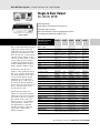
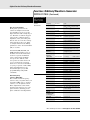
Basic DC Power Supplies essential features for a tight budget
Single & Dual Output
30-100 W GPIB
E3640A-E3649A
Dual range outputs
Small, compact size for bench and system use
Low output ripple and noise
Built-in measurements and basic programmable features
Over-voltage protection to ensure DUT safety
Specifications
E3640A
E3641A
E3642A
E3643A
E3644A
Number of outputs
1
1
1
1
1
GPIB
Yes
Yes
Yes
Yes
Yes
Voltage
Current
0 to 8 V
3A
0 to 35 V
0.8 A
0 to 8 V
5A
0 to 35 V
1.4 A
0 to 8 V
8A
Voltage
Current
0 to 20 V
1.5 A
0 to 60 V
0.5 A
0 to 20 V
2.5 A
0 to 60 V
0.8 A
0 to 20 V
4A
Power (max)
30 W
30 W
50 W
50 W
80 W
(at 0˚ to 55˚ C unless
otherwise specified)
These isolated dual range DC power
supplies provide the stable and
reliable DC power that the manufacturing test system designer needs.
These models offer constant-voltage/
constant-current outputs, so they
can serve as either voltage or current
sources. They can be used either
for manual or automated testing,
and have VXIPlug&Play drivers to
further simplify computer control.
The E3640A Series DC power
supplies can be quickly integrated
into a test system. Both front and
rear panel terminals are provided
for easy wiring. Remote sensing
eliminates the errors in voltage
regulation due to voltage drops in
the load leads. Delicate DUTs are
protected by overvoltage protection.
Up to 5 operating states can be
stored for later recall.
The E3640A Series DC power
supplies are intended for manufacturing test systems where moderate
speed and accuracy are required.
For systems which require even
higher accuracy for programming
or measurement, or where test
throughput must be optimized,
consider the Agilent 6600A and
N6700 Series of Performance
DC Power Supplies.
DC outputs
Load and line regulation
Voltage
<0.01% + 3 mV <0.01% + 3 mV <0.01% + 3 mV <0.01% + 3 mV <0.01% + 3 mV
Current
<0.01% + 250 µA <0.01% + 250 µA <0.01% + 250 µA <0.01% + 250 µA <0.01% + 250 µA
Ripple and noise
from 20 Hz to 20 MHz
Normal-Mode Voltage
<500 µVrms
5 mVp-p
<1 mVrms
8 mVp-p
<500 µVrms
5 mVp-p
<1 mVrms
8 mVp-p
<500 µVrms
5 mVp-p
Normal-Mode Current
<4.0 mArms
<4.0 mArms
<4.0 mArms
<4.0 mArms
<4.0 mArms
Common-Mode Current
<1.5 µArms
<1.5 µArms
<1.5 µArms
<1.5 µArms
<1.5 µArms
Programming accuracy at 25˚C ±5˚C
Voltage
<0.05% +
10 mV
10 mV
10 mV
10 mV
10 mV
Current
<0.2% +
10 mA
10 mA
10 mA
10 mA
10 mA
Readback accuracy at 25˚C ±5˚C
Voltage
<0.05% +
5 mV
5 mV
5 mV
5 mV
5 mV
Current
<0.15% +
5 mA
5 mA
5 mA
5 mA
5 mA
Program resolution
Voltage
5 mV
5 mV
5 mV
5 mV
5 mV
Current
1 mA
1 mA
1 mA
1 mA
1 mA
Readback resolution
Voltage
2 mV
2 mV
2 mV
2 mV
2 mV
Current
1 mA
1 mA
1 mA
1 mA
1 mA
Meter resolution
Voltage
10 mV
10 mV
10 mV
10 mV
10 mV
Current
1 mA
1 mA
1 mA
1 mA
1 mA
Transient response
<50 µsec for output to recover to within 15 mV following a change in
output current from full load to half load or vice versa.
*Maximum current is derated 1% per °C from 40°C to 55°C
More detailed specifications at www.agilent.com/find/E3600
23
Basic DC Power Supplies essential features for a tight budget
Single & Dual Output: 30-100 W GPIB (Continued)
Specifications
E3645A
E3646A
E3647A
E3648A
E3649A
Number of outputs
1
2
2
2
2
GPIB
Yes
Yes
Yes
Yes
Yes
Voltage
Current
0 to 35 V
2.2 A
0 to 8 V
3A
0 to 35 V
0.8 A
0 to 8 V
5A
0 to 35 V
1.4 A
Voltage
Current
0 to 60 V
1.3 A
0 to 20 V
1.5 A
0 to 60 V
0.5 A
0 to 20 V
2.5 A
0 to 60 V
0.8 A
Power (max)
80 W
60 W
60 W
100 W
100 W
(at 0˚ to 55˚ C unless
otherwise specified)
Application Notes:
Understanding Linear Power Supply
Operation (AN1554)
5989-2291EN
10 Practical Tips You Need to
Know About Your Power Products
5965-8239E
Modern Connectivity Using USB and LAN I/O Converters
(AN 1475-1)
5989-0123EN
Supplemental Characteristics
for all model numbers
DC Floating Voltage: Output terminals can
be floated up to ±240 Vdc from chassis
ground
DC outputs
Load and line regulation
Voltage
<0.01% +
3 mV
3 mV
3 mV
3 mV
3 mV
Current
<0.01% +
250 µA
250 µA
250 µA
250 µA
250 µA
Normal-Mode Voltage
<1 mVrms
8 mVp-p
<500 µVrms
5 mVp-p
<1 mVrms
8 mVp-p
<500 µVrms
5 mVp-p
<1 mVrms
8 mVp-p
Normal-Mode Current
<4.0 mArms
<4.0 mArms
<4.0 mArms
<4.0 mArms
<4.0 mArms
Common-Mode Current
<1.5 µArms
<1.5 µArms
<1.5 µArms
<1.5 µArms
<1.5 µArms
Ripple and noise
from 20 Hz to 20 MHz
Programming accuracy at 25˚C ±5˚C
Voltage
<0.05% +
(<0.1% + 25 mA for output 2)
10 mV
10 mV
10 mV
10 mV
10 mV
Remote Sensing: Up to 1 V can be dropped
in each load lead. The drop in the load
leads subtracts from the voltage available
for the load.
Current
<0.2% +
10 mA
10 mA
10 mA
10 mA
10 mA
<0.05% +
(<0.1% + 25 mV for output 2)
5 mV
5 mV
5 mV
5 mV
5 mV
Settling Time: Less than 90msec for the
output voltage to change from 1% to 99%
or vice versa following the receipt of
VOLTage or APPLy command via direct
GPIB or RS-232 interface.
Current
<0.15% +
(<0.15% + 10 mA for output 2)
5 mA
5 mA
5 mA
5 mA
5 mA
Voltage
5 mV
5 mV
5 mV
5 mV
5 mV
Current
1 mA
1 mA
1 mA
1 mA
1 mA
Voltage
2 mV
2 mV
2 mV
2 mV
2 mV
Current
1 mA
1 mA
1 mA
1 mA
1 mA
Product Regulation:
Designed to comply with UL3111-1;
certified to CSA 22.2 No. 1010.1; conforms
to IEC 1010-1; complies with EMC
directive 89/336/EEC(Group1, Class A)
Readback accuracy at 25˚C ±5˚C
Voltage
Program resolution
Readback resolution
Meter resolution
OVP Accuracy: 0.5% + 0.5 V, activation
time: ≥3 V, <1.5 ms, and <3 V, <10 ms
Voltage
10 mV
10 mV
10 mV
10 mV
10 mV
Current
1 mA
1 mA
1 mA
1 mA
1 mA
Isolation: ±240 Vdc
Transient response
<50 µsec for output to recover to within 15 mV following a change in
output current from full load to half load or vice versa.
Stability: Voltage <0.02% + 2 mV;
Current <0.1% + 1 mA
*Maximum current is derated 1% per °C from 40°C to 55°C
Temperature Coefficient: <0.01% + 3 mV,
<0.02% + 3 mA change per˚C
over operating range 0-40˚C
after 30 minute warm-up
Size: (E3640A-E3645A)
254.4 mm W x 104 mm H x 374 mm D
(10 in. x 4.1 in. x 14.8 in.)
(E3646A-E3649A)
213 mm W x 133 mm H x 348 mm D
(8.4 in. x 5.2 in. x 13.7 in.)
Software Driver:
• IVI-COM
• VXIPlug&Play
• IntuiLink Connectivity Software
Warranty Period: One year
Weight: E3640A, E3641A: 5.3 kg (11.7 lbs)
E3642A, E3643A: 6.2 kg (13.7 lbs)
E3644A, E3645A: 6 kg (13.2 lbs)
E3646A, E3647A: 7.4 kg (16.3 lbs)
E3648A, E3649A: 9.5 kg (20.9 lbs)
Ordering Information
Opt 0E3 207 to 253 Vac, 47 to 63 Hz
Opt 0E9 90 to 110 Vac,
47 to 63 Hz (Japan only)
Opt 0EM 104 to 126 Vac, 47 to 63 Hz
Opt 1CM Rack mount kit
(E3640A-E3645A p/n5063-9240;
E3646A-E3649A p/n 5063-9243)
Opt 0L2 Extra documentation package
Opt 0B0 Delete documentation
More detailed specifications at www.agilent.com/find/E3600
24
Basic DC Power Supplies essential features for a tight budget
Single-Output, Autoranging
200 W and 1000 W
Autoranging Output:
P1
V1
Volts
6010A, 6011A, 6012B, 6015A
P2
V2
V3
Autoranging outputs provide maximum power
at a variety of operating voltages
I1
Analog/resistance control of output voltage and current
Series and auto-parallel connections enable greater output flexibility
Protection features to ensure DUT safety
Specifications
P3
I2
I3
Amps
6010A
6011A
6012B
6015A
Number of outputs
1
1
1
1
GPIB
No
No
No
No
Voltage
0 to 200 V
0 to 20 V
0 to 60 V
0 to 500 V
Current
0 to 17 A
0 to 120 A
0 to 50 A
0 to 5 A
(at 0˚ to 55˚ C unless
otherwise specified)
This series of DC power supplies
take the place of multiple power
supplies on your test bench by
providing maximum power at
a variety of operating points.
They have ten-turn front panel
pots to allow precise local control.
These power supplies also may be
connected in auto-parallel or
series with their corresponding
GPIB unit (6030 Series), as part
of a test system.
Application Notes:
10 Practical Tips You Need to Know
About Your Power Products
5965-8239E
Output ratings
Maximum power
Watts
Autoranging output
1,200 W
1,064 W
1,200 W
1,050 W
V1, I1
200 V, 5 A
20 V, 50 A
60 V, 17.5 A
500 V, 2 A
V2, I2
120 V, 10 A
14 V, 76 A
40 V, 30 A
350 V, 3 A
V3, I3
60 V, 17 A
7 V, 120 A
20 V, 50 A
200 V, 5 A
Ripple and noise, 20 Hz to 20 MHz
Voltage rms
22 mV
8 mV
8 mV
50 mV
p-p
50 mV
50 mV
40 mV
160 mV
Current rms
15 mA
120 mA
25 mA
50 mA
Load regulation
Voltage
0.01%+
5 mV
3 mV
5 mV
13 mV
Current
0.01%+
10 mA
15 mA
10 mA
35 mA
Transient response time
10% step change
Time
2 ms
2 ms
2 ms
5 ms
Level
150 mV
100 mV
100 mV
200 mV
Supplemental Characteristics
(Non-warranted characteristics determined by design that are
useful in applying the product)
Programming resolution
Voltage
50 mV
5 mV
15 mV
Current
4.25 mA
30 mA
12.5 mA
1.25 mA
DC floating voltage
either terminal can be grounded
or floated from chassis ground
±550 V
±240 V
±240 V
±550 V
AC input current
100 Vac
24 A
24 A
24 A
24 A
120 Vac
24 A
24 A
24 A
24 A
220 Vac
15 A
15 A
15 A
15 A
240 Vac
14 A
14 A
14 A
14 A
Net
16.3 kg (36 lb)
17.2 kg (38 lb)
16.3 kg (36 lb)
16.3 kg (36 lb)
Shipping
21.8 kg (48 lb)
22.7 kg (50 lb)
21.8 kg (48 lb)
21.8 kg (48 lb)
Weight
125 mV
More detailed specifications at www.agilent.com/find/6010
25
Basic DC Power Supplies essential features for a tight budget
Single-Output, Autoranging
200 W and 1000 W (Continued)
Ordering Information
Supplemental Characteristics
for all model numbers
Remote Sensing: Up to 2 V drop in each
lead. Voltage regulation specification met
with up to 0.5 V drop, but degrades for
greater drops.
Modulation: (analog programming of
output voltage and current)
Input signal: 0 to 5 V or 0 to 4 k Ohms
Regulatory Compliance: Certified to
CSA556B; conforms to IEC 61010-1.
Size: 425.5 mm W x 132.6 mm H x 516.4 mm D
(16.75 in x 5.25 in x 20.33 in).
Warranty: One year
Opt 120 104 to 127 Vac, 47 to 63 Hz
Opt 220 191 to 233 Vac, 48 to 63 Hz
Opt 240 209 to 250 Vac, 48 to 63 Hz
* Opt 908 Rack-mount Kit (p/n 5062-3977)
* Opt 909 Rack-mount Kit with Handles.
(p/n 5062-3983)
Opt 0L1 Full documentation on
CD-ROM, and printed standard
documentation package
Opt 0L2 Extra copy of standard
printed documentation package
Opt 0B0 Full documentation on
CD-ROM only
Opt J01 Stabilization for loads up to 10 Henries
A line cord option must be specified,
see the AC line voltage and cord section.
*Support rails required
Accessories
1494-0060 Rack Slide Kit
E3663AC Support rails for
Agilent rack cabinets
Agilent Models: 6010A, 6011A, 6012B, 6015A
Top
Terminal Strip Detail
VM Screw Size
M3.5 x 0.6
IM
M
VP
425mm
16.75"
IP
P
B6
Size
0.6
B1
+S
-S
2.5mm
0.1"
421.6mm
16.6"
12.7mm
0.5"
132.6mm
5.2"
128mm
5.04"
77mm
3.03"
Rear
Side
12.7mm
0.5"
More detailed specifications at www.agilent.com/find/6010
26
Basic DC Power Supplies essential features for a tight budget
Single-Output, Autoranging
200 W and 1000 W GPIB
6030A, 6031A, 6032A, 6033A, 6035A, 6038A
Autoranging outputs provide maximum power at a variety
Autoranging Output:
of operating voltages
P1
V1
Analog/resistance control of output voltage and current
P2
Volts V2
Series and auto-parallel connections of multiple supplies
V3
Built-in measurements and advanced programmable features
I1
I2
Protection features to ensure DUT safety
Amps
Specifications
6030A
6031A
6032A
6033A
6035A
6038A
Number of outputs
1
1
1
1
1
1
GPIB
Yes
Yes
Yes
Yes
Yes
Yes
Output Voltage
0 to 200 V
0 to 20 V
0 to 60 V
0 to 20 V
0 to 500 V
0 to 60 V
Output Current
0 to 17 A
0 to 120 A
0 to 50 A
0 to 30 A
0 to 5 A
0 to 10 A
Maximum power watts
1,200 W
1,064 W
1,200 W
242 W
1,050 W
240 W
V1, I1
200 V, 5 A
20 V, 50 A
60 V, 17.5 A 20 V, 10 A
500 V, 2 A
60 V, 3.3 A
V2, I2
120 V, 10 A 14 V, 76 A
40 V, 30 A
14 V, 17.2 A 350 V, 3 A
40 V, 6 A
V3, I3
60 V, 17 A
7 V, 120 A
20 V, 50 A
6.7 V, 30 A
200 V, 5 A
20 V, 10 A
Voltage
0.035%
+145 mV
0.035%
+15 mV
0.035%
+40 mV
0.035%
+9 mV
0.25%
+400 mV
0.035%
+40 mV
Current
0.2%
+25 mA
0.25%
+250 mA
0.2%
+85 mA
0.15%
+20 mA
0.3%
+63 mA
0.09%
+10 mA
Voltage rms
p-p
22 mV
50 mV
8 mV
50 mV
8 mV
40 mV
3 mV
30 mV
50 mV
160 mV
3 mV
30 mV
Current rms
(at 0˚ to 55˚ C unless
otherwise specified)
This series of 200 watt and 1000
watt DC power supplies take the
place of multiple power supplies
in your test system by providing
maximum power at a variety of
operating points.
Output ratings
Autoranging output
Industry standard SCPI commands
and VXIPlug&Play drivers make
system integration easy. Using the
serial link, up to 16 power supplies
can be connected through one
GPIB address. These power supplies
have excellent electrical efficiency,
making them a good choice for
large systems.
Programming accuracy
at 25°C ±5°C
Ripple and noise
20 Hz to 20 MHz
Readback accuracy
at 25°C ±5°C
Application Notes:
10 Hints for Using Your Power Supply
to Decrease Test Time
5968-6359E
15 mA
120 mA
25 mA
30 mA
50 mA
5 mA
Voltage
0.08%
+80 mV
0.08%
+7 mV
0.08%
+20 mV
0.07%
+6 mV
0.5%
+200 mV
0.07%
+50 mV
Current
0.36%
+15 mA
0.4%
+100 mA
0.36%
+35 mA
0.3%
+25 mA
0.5%
+50 mA
0.2%
+11 mA
0.01%+
5 mV
3 mV
5 mV
2 mV
40 mV
3 mV
0.01%+
10 mA
0.01%+
15 mA
0.01%+
10 mA
0.01%+
9 mA
0.03%+
34 mA
0.01%+
5 mA
Load regulation
Voltage
10 Practical Tips You Need to
Know About Your Power Products
5965-8239E
Current
Agilent DC Power Supplies
for Base Station Testing
5988-2386EN
Voltage
0.01%+
5 mV
0.01%+
2 mV
0.01%+
3 mV
0.01%+
1 mV
0.03%+
17 mV
0.01%+
2 mV
Current
0.01%+
5 mA
0.01%+
25 mA
0.01%+
10 mA
0.01%+
6 mA
0.03%+
17 mA
0.01%+
2 mA
2 ms
150 mV
2 ms
100 mV
2 ms
100 mV
1 ms
50 mV
5 ms
200 mV 7
1 ms
5 mV
Line regulation
Transient response time
10% step change
Time
Level
More detailed specifications at www.agilent.com/find/6030
27
P3
I3
Basic DC Power Supplies essential features for a tight budget
Autoranging: 200 W and 1000 W GPIB (Continued)
Specifications
6030A
6031A
6032A
6033A
6035A
6038A
(at 0˚ to 55˚ C unless
otherwise specified)
Supplemental Characteristics
for all model numbers
Supplemental Characteristics
(Non-warranted characteristics determined by design and
useful in applying the product)
Programming resolution Voltage
50 mV
5 mV
15 mV
5 mV
125 mV 1
5 mV
4.25 mA
30 mA
12.5 mA
7.5 mA
1.25 mA
2.5 mA
DC floating voltage
either terminal can be grounded
or floated from chassis ground
±550 V
±240 V
±240 V
±240 V
±550 V
±240 V
AC input current
Current
Remote Sensing: Up to 2 V drop in each
lead. Voltage regulation specification met
with up to 0.5 V drop, but degrades for
greater drops.
Modulation: (analog programming of
output voltage and current)
Input signal: 0 to 5 V or 0 to 4 k Ohms
Software Driver:
VXIPlug&Play
100 Vac
24 A
24 A
24 A
6A
24 A
6A
120 Vac
24 A
24 A
24 A
6.5 A
24 A
6.5 A
220 Vac
15 A
15 A
15 A
3.8 A
15 A
3.8 A
240 Vac
14 A
14 A
14 A
3.6 A
14 A
3.6 A
Net
16.3 kg
(36 lb)
17.2 kg
(38 lb)
16.3 kg
(36 lb)
9.6 kg
(21 lb)
16.3 kg
(36 lb)
9.6 kg
(21 lb)
Shipping
21.8 kg
(48 lb)
22.7 kg
(50 lb)
21.8 kg
(48 lb)
11.4 kg
(25 lb)
21.8 kg
(48 lb)
11.4 kg
(25 lb)
Weight
Warranty: One year
Size: 6030A–32A, 6035A:
425.5 mm W x 132.6 mm H x 503.7 mm D
(16.75 in x 5.25 in x 19.83 in).
6033A, 6038A:
212.3 mm W x 177.0 mm H x 516.4 mm D
(8.36 in x 6.97 in x 17.87 in).
Agilent Models: 6030A, 6031A, 6032A, 6035A
Top
Terminal Strip Detail
VM Screw Size
M3.5 x 0.6
IM
M
VP
425mm
16.75"
IP
P
B6
B1
Size
0.6
+S
-S
2.5mm
0.1"
421.6mm
16.6"
132.6mm
5.2"
128mm
5.04"
77mm
3.03"
Rear
Side
12.7mm
0.5"
More detailed specifications at www.agilent.com/find/6030
28
12.7mm
0.5"
Basic DC Power Supplies essential features for a tight budget
Autoranging: 200 W and 1000 W GPIB (Continued)
Ordering Information
Opt 001 Front panel has only line switch,
line indicator, and OVP adjust
(6030A–33A and 6038A only)
Opt 100 87 to 106 Vac, 48 to 63 Hz
(power supply output is derated to 75%)
Opt 120 104 to 127 Vac, 47 to 63 Hz
Opt 220 191 to 233 Vac, 48 to 63 Hz
Opt 240 209 to 250 Vac, 48 to 63 Hz
Opt 800 Rack-mount Kit for Two
Half-rack Units Side by Side.
Lock link Kit p/n 5061-9694 and
7 in Rack adapter Kit 5063-9215
* Opt 908 Rack-mount Kit for a Single
Half-rack Unit 6033A and 6038A
(with blank filler panel); p/n 5062-3960,
6030A–32A and 6035A; p/n 5062-3977
* Opt 909 Rack-mount Kit with Handles.
For 6030A–32A, 6035A; p/n 5062-3983
Accessories
Opt 0L1 Full documentation on
CD-ROM, and printed standard
documentation package
Opt 0L2 Extra copy of standard
printed documentation package
Opt 0B3 Service Manual
Opt 0B0 Full documentation
on CD-ROM only
Opt J01 Stabilization for loads up to
10 Henries (not available on 6033A)
5080-2148 Serial Link Cable,
2 m (6.6 ft)
1494-0060 Rack Slide Kit
E3663AC Support rails
for Agilent rack
cabinets
A line cord option must be specified,
see the AC line voltage and cord section.
* Support rails required
Agilent Models: 6033A, 6038A
Terminal Strip Detail
VM
IM
M
Top
31.8mm
1.25"
VP
IP
P
B6
212.3mm
8.36"
B1
Screw Size
M3.5 x 0.6
208.8mm
8.22"
19.6mm
0.77"
177.0mm
6.97"
170.6mm
6.72"
Rear
13.5mm
0.53"
16.5mm
0.65"
421.6mm
16.6"
22.0mm
0.87"
Side
More detailed specifications at www.agilent.com/find/6030
29
Basic DC Power Supplies essential features for a tight budget
Single-Output
750 W & 1500 W GPIB, LAN, USB
N5741A*
Small size: 1 U high
Universal AC input (85-265 Vac)
Analog/resistance control of output voltage and current
3
Parallel and series connection of multiple supplies
N5741A - N5772A
Built-in measurements and advanced programmable features
Protection features to ensure DUT safety
Specifications
N5741A
N5742A
N5743A N5744A
N5745A
N5746A
(at 0˚ to 40˚ C unless
otherwise specified)
The N5700 Series is a family of
affordable 750 W and 1500 W
switching regulated, single-output
programmable DC power supplies.
They offer 24 models for simple
DC power application where speed
and accuracy are not the primary
concern. They provide stable output
power, built-in voltage and current
measurement, and output voltage
and current from 6 V to 600 V and
1.3 A to 180 A.
Small, High-Density Package
The N5700 provides up to 1500 W
in a small space-saving 1 U-high,
19-inch wide package. Its air vents
are in the front, side and rear (not
on the top or bottom), so you can
stack other instruments directly
above or below it to save valuable
rack space.
Universal AC input
All models have universal AC
input so they can be automatically
operated from any AC mains input
worldwide. They can be operated
from line voltages of 85 – 265 VAC,
47 to 63 Hz, with no switch to
set or fuses to change when you
switch from one voltage standard
to another. They also provide
power factor correction.
Number of Outputs
1
1
1
1
1
1
GPIB, LAN, USB
Yes
Yes
Yes
Yes
Yes
Yes
Voltage
6V
8V
12.5 V
20 V
30 V
40 V
Current
100 A
90 A
60 A
38 A
25 A
19 A
Power
600 W
720 W
750 W
760 W
750 W
760 W
3 mV
4 mV
6.25 mV
10 mV
15 mV
20 mV
100 mA
90 mA
60 mA
38 mA
25 mA
19 mA
CV p-p (Up to 20 MHz)
60 mV
60 mV
60 mV
60 mV
60 mV
60 mV
CV rms (From 5 Hz – 1 MHz)
8 mV
8 mV
8 mV
8 mV
8 mV
8 mV
Ouput Ratings
Programming Accuracy
Voltage
0.05%+
Current
0.1%+
Output Ripple and Noise
Readback Accuracy
Voltage
0.1%+
6 mV
8 mV
12.5 mV
20 mV
30 mV
40 mV
Current
0.1%+
300 mA
270 mA
180 mA
114 mA
75 mA
57 mA
Voltage
2.6 mV
2.8 mV
3.25 mV
4 mV
5 mV
6 mV
Current
25 mA
23 mA
17 mA
12.6 mA
10 mA
8.8 mA
Voltage
2.6 mV
2.8 mV
3.25 mV
4 mV
5 mV
6 mV
Current
12 mA
11 mA
8 mA
5.8 mA
4.5 mA
3.9 mA
≤1.5 ms
≤1.5 ms
≤1.5 ms
≤1 ms
≤1 ms
≤1 ms
Load Regulation
(change from 10% to 90%)
Line Regulation
(change from 85-132 VAC input
or 170-265 VAC input)
Transient Response Time1
Time
Notes:
1 Time for output voltage to recover within 0.5% of its rated output for a load change from
10 to 90% of its rated output current. Voltage set point from 10% to 100% of rated output
* AC input connector: IEC 320 connector for 750 W models, and wire clamp connector for 1500 W models
More detailed specifications at www.agilent.com/find/N5700
30
Basic DC Power Supplies essential features for a tight budget
Single-Output 750 W & 1500 W GPIB, LAN, USB
(Continued)
Specifications
N5741A
N5742A
N5743A N5744A
N5745A
N5746A
(at 0˚ to 40˚ C unless
otherwise specified)
Supplemental Characteristics
Extensive Device Protection
To safeguard your device from
damage, the N5700 Series power
supplies provide over-temperature,
over-current and over-voltage protect (OVP) to shut down the power
supply output when a fault occurs.
They also offer an undervoltage
limit (UVL) that prevents adjustment of the output voltage below
a certain limit. The combination
of UVL and OVP capabilities lets
you create a protection window
for sensitive load circuitry
(Non-warranted characteristics determined by design
that are useful in applying the product)
Output Response Time
(settle to within ±1.0% of the
rated output, with a resistive load)
Up, full load
0.08 s
0.08 s
0.08 s
0.08 s
0.08 s
0.08 s
Down, full load
0.05 s
0.05 s
0.05 s
0.05 s
0.08 s
0.08 s
Down, no load
0.5 s
0.6 s
0.7 s
0.8 s
0.9 s
1.0 s
1V
1V
1V
1V
1.5 V
2V
200 mA
180 mA
120 mA
76 mA
63 mA
48 m
Voltage
0.72 mV
0.96 mV
1.5 mV
2.4 mV
3.6 mV
4.8 mV
Simplify System Connection
Current
12 mA
10.8 mA
7.2 mA
4.56 mA
3 mA
2.3 mA
The N5700 offers many system
oriented features to simplify and
accelerate test system development.
They support the industry standard
SCPI commands and come standard
with software drivers.
Notes:
With built-in GPIB, Ethernet/LAN,
and USB 2.0 interfaces, the N5700
gives you the flexibility to use your
I/O interface of choice today and
in the future.
Additionally, the built-in Web
server lets you operate, configure,
and monitor the N5700 remotely
via a standard browser such as
Microsoft Internet Explorer.
Remote Sense Compensation
Volts/load lead
Output Ripple and Noise2
CC rms
Programming Resolution/
Measurement Resolution
2 From 5 Hz – 1 MHz, at 10% to 100% of output voltage at full load
(for 6 V units from 33% to 100% of output voltage)
Agilent Models: N5741A - N5772A
VOLTAGE
DC VOLTS
N5749A
43.6 mm
100 V / 7.5 A / 750 W
Sytem DC Power Supply
PROT FINE
OVP
LIMIT UVL
DC AMPS
OCP
CURRENT
REM OUT ON
POWER
482.8 mm
LINK
GPIB
J2
SW1
10/100 Ethernet
TX
+V
–V
J1
ON
OFF
+S+LSNC-LC-S
123456789
ANALOG PROGRAMMING
The N5700 includes a compatibility
command set for the Xantrex XFR
series power supplies, the Sorensen
DLM series power supplies, and the
Agilent 603x series power supplies.
This simplifies system integration
when converting to the N5700.
AC INPUT
NOT ACTIVE
Command Compatibility
422.8 mm
507.0 mm
A
A
A
21.0 mm
57.8
mm
92.0 mm
92.0 mm
433.0 mm
More detailed specifications at www.agilent.com/find/N5700
31
Basic DC Power Supplies essential features for a tight budget
Single-Output 750 W & 1500 W GPIB, LAN, USB
(Continued)
Specifications
N5747A
N5748A
N5749A N5750A
N5751A
N5752A
Number of Outputs
1
1
1
1
1
1
GPIB, LAN, USB
Yes
Yes
Yes
Yes
Yes
Yes
(at 0˚ to 40˚ C unless
otherwise specified)
Analog/Resistance Programming
For greater programming flexibility
and to minimize the time associated
with computer interaction, both the
output voltage and current can be
controlled by an external voltage
or resistance programming signal.
Connect Multiple Units in
Parallel and Series
Should you need greater output
power, the N5700 Series power
supplies give you the flexibility to
connect in parallel up to four similarly rated units for greater output
current and connect two similarly
rated units in series for greater
output voltage (see DC float voltage
information)
Fan Speed Control
Lab bench use is enhanced by the
fan speed control, which helps to
minimize the acoustic noise.
Ouput Ratings
Voltage
60 V
80 V
100 V
150 V
300 V
600 V
Current
12.5 A
9.5 A
7.5 A
5A
2.5 A
1.3 A
Power
750 W
760 W
750 W
750 W
750 W
780 W
30 mV
40 mV
50 mV
75 mV
150 mV
300 mV
12.5 mA
9.5 mA
7.5 mA
5 mA
2.5 mA
1.3 mA
CV p-p (Up to 20 MHz)
60 mV
80 mV
80 mV
100 mV
150 mV
300 mV
CV rms (From 5 Hz – 1 MHz)
8 mV
8 mV
8 mV
12 mV
20 mV
60 mV
Programming Accuracy
Voltage
0.05%+
Current
0.1%+
Output Ripple and Noise
Readback Accuracy
Voltage
0.1%+
60 mV
80 mV
100 mV
150 mV
300 mV
600 mV
Current
0.1%+
37.5 mA
28.5 mA
22.5 mA
15 mA
7.5 mA
3.9 mA
Voltage
8 mV
10 mV
12 mV
17 mV
32 mV
62 mV
Current
7.5 mA
6.9 mA
6.5 mA
6 mA
5.5 mA
5.26 mA
Voltage
8 mV
10 mV
12 mV
17 mV
32 mV
62 mV
Current
3.25 mA
2.95 mA
2.75 mA
2.5 mA
2.25 mA
2.13 mA
≤ 1 ms
≤ 1 ms
≤ 2 ms
≤ 2 ms
≤ 2 ms
Load Regulation
(change from 10% to 90%)
Line Regulation
(change from 85-132 VAC input
or 170-265 VAC input)
Transient Response Time1
Application Notes:
Time
≤ 1 ms
Side-by-Side Comparison:
Agilent N5700 System DC Source
and Sorensen DLM Power Supply
5989-1628EN
Supplemental Characteristics
(Non-warranted characteristics determined by design
that are useful in applying the product)
Side-by-Side Comparison:
Agilent N5700 System DC Source
and Xantrex XFR DC Power Supply
5989-1630EN
Trends in Programmable Medium Power
(~1 kW) System DC Power Supplies
5989-1331EN
Output Response Time
(settle to within ±1.0% of the
rated output, with a resistive load)
Up, full load
0.08 s
0.15 s
0.15 s
0.15 s
0.15 s
0.25 s
Down, full load
0.08 s
0.15 s
0.15 s
0.15 s
0.15 s
0.30 s
Down, no load
1.1 s
1.2 s
1.5 s
2.0 s
3.0 s
4.0 s
3V
4V
5V
5V
5V
5V
38 mA
29 mA
23 mA
18 mA
13 mA
8 mA
Voltage
7.2 mV
9.6 mV
12 mV
18 mV
36 mV
72 mV
Current
1.5 mA
1.14 mA
0.9 mA
0.6 mA
0.3 mA
0.156 mA
Remote Sense Compensation
Volts/load lead
Output Ripple and Noise2
CC rms
Notes:
1 Time for output voltage to recover within
0.5% of its rated output for a load change from
10 to 90% of its rated output current. Voltage
set point from 10% to 100% of rated output
Programming Resolution/
Measurement Resolution
2 From 5 Hz – 1 MHz, at 10% to 100% of output
voltage at full load (for 6 V units from 33% to
100% of output voltage)
More detailed specifications at www.agilent.com/find/N5700
32
Basic DC Power Supplies essential features for a tight budget
Single-Output 750 W & 1500 W GPIB, LAN, USB
(Continued)
Specifications
N5761A
N5762A
N5763A N5764A
N5765A
N5766A
Number of Outputs
1
1
1
1
1
1
GPIB, LAN, USB
Yes
Yes
Yes
Yes
Yes
Yes
Voltage
6V
8V
12.5 V
20 V
30 V
40 V
Current
180 A
165 A
120 A
76 A
50 A
38 A
Power
1080 W
1320 W
1500 W
1520 W
1500 W
1520 W
3 mV
4 mV
6.25 mV
10 mV
15 mV
20 mV
180 mA
165 mA
120 mA
76 mA
50 mA
38 mA
(at 0˚ to 40˚ C unless
otherwise specified)
Supplemental Characteristics
for all model numbers
Command Processing Time: Average time
required for the output voltage to begin
to change following receipt of digital
data is 55 ms.
Ouput Ratings
Programming Accuracy
Voltage
0.05%+
DC Floating Voltage:
Current
0.1%+
6 V to 60 V units
No output terminal may be more than
±60 VDC from any other terminal or
chassis ground
Output Ripple and Noise
80 V to 600 V units
No output terminal may be more than
±600 VDC from any other terminal or
chassis ground
Modulation: (Analog programming
of output voltage and current)
Input Signal: selectable,
0 to 5 V/0 to 10 V full scale
Input Impedance: selectable,
0 to 5 kΩ/0 to 10 kΩ full scale
I/O Interface: GPIB, LAN,
USB standard
CV p-p (Up to 20 MHz
60 mV
60 mV
60 mV
60 mV
60 mV
60 mV
CV rms (From 5 Hz – 1 MHz
8 mV
8 mV
8 mV
8 mV
8 mV
8 mV
Readback Accuracy
Voltage
0.1%+
6 mV
8 mV
12.5 mV
20 mV
30 mV
40 mV
Current
0.1%+
540 mA
495 mA
360 mA
228 mA
150 mA
114 mA
Voltage
2.6 mV
2.8 mV
3.25 mV
4 mV
5 mV
6 mV
Current
41 mA
38 mA
29 mA
20.2 mA
15 mA
12.6 mA
Voltage
2.6 mV
2.8 mV
3.25 mV
4 mV
5 mV
6 mV
Current
20 mA
18.5 mA
14 mA
9.6 mA
7 mA
5.8 mA
Time
≤ 1.5 ms
≤ 1.5 ms
≤ 1.5 ms
≤ 1 ms
≤ 1 ms
≤ 1 ms
Supplemental Characteristics
(Non-warranted characteristics determined by design
that are useful in applying the product)
Load Regulation
(change from 10% to 90%)
Line Regulation
(change from 85-132 VAC input
or 170-265 VAC input)
Transient Response Time1
Software Driver:
• IVI-COM
• LabVIEW
AC Input:
Input Range: 85 – 265 VAC; 47 – 63 Hz
Output Response Time
(settle to within ±1.0% of the
rated output, with a resistive load)
Up, full load
0.08 s
0.08 s
0.08 s
0.08 s
0.08 s
0.08 s
Input Current 750 W: 10.5 A at 100 VAC
nominal; 5 A at 200 VAC nominal
Down, full load
0.05 s
0.05 s
0.05 s
0.05 s
0.08 s
0.08 s
Input Current 1500 W: 21 A at 100 VAC
nominal; 11 A at 200 VAC nominal
Down, no load
0.5 s
0.6 s
0.7 s
0.8 s
0.9 s
1.0 s
Remote Sense Compensation
1V
1V
1V
1V
1.5 V
2V
360 mA
330 mA
240 mA
152 mA
125 mA
95 mA
Voltage
0.72 mV
0.96 mV
1.5 mV
2.4 mV
3.6 mV
4.8 mV
Current
21.6 mA
19.8 mA
14.4 mA
9.12 mA
6 mA
4.6 mA
Volts/load lead
Output Ripple and Noise2
CC rms
Notes:
1 Time for output voltage to recover within
0.5% of its rated output for a load change from
10 to 90% of its rated output current. Voltage
set point from 10% to 100% of rated output
Programming Resolution/
Measurement Resolution
2 From 5 Hz – 1 MHz, at 10% to 100% of output
voltage at full load (for 6 V units from 33% to
100% of output voltage)
More detailed specifications at www.agilent.com/find/N5700
33
Basic DC Power Supplies essential features for a tight budget
Single-Output 750 W & 1500 W GPIB, LAN, USB
(Continued)
Specifications
N5767A
N5768A
N5769A N5770A
N5771A
N5772A
Number of Outputs
1
1
1
1
1
1
GPIB, LAN, USB
Yes
Yes
Yes
Yes
Yes
Yes
Voltage
60 V
80 V
100 V
150 V
300 V
600 V
Current
25 A
19 A
15 A
10 A
5A
2.6 A
Power
1500 W
1520 W
1500 W
1500 W
1500 W
1560 W
(at 0˚ to 40˚ C unless
otherwise specified)
Power Factor: 0.99 at nominal input
and rated output power
Regulatory Compliance: European EMC
directive 89/336/EEC for Class A
products, Australian C-Tick mark,
This ISM device complies with
Canadian ICES-001. Cet appareil
ISM est conforme à la norme NMB-001
du Canada. European Low Voltage
Directive 73/23/EEC.
Ouput Ratings
Programming Accuracy
Voltage
0.05%+
30 mV
40 mV
50 mV
75 mV
150 mV
300 mV
Current
0.1%+
25 mA
19 mA
15 mA
10 mA
5 mA
2.6 mA
Output Ripple and Noise
Size: 43.6 mm H x 422.8 mm W x
432.8 mm D (1.72 in x 16.65 in x 17.04 in),
excluding connectors and handles
CV p-p (Up to 20 MHz)
60 mV
80 mV
80 mV
100 mV
150 mV
300 mV
CV rms (From 5 Hz – 1 MHz)
8 mV
8 mV
8 mV
12 mV
20 mV
60 mV
Weight: Net, 750 W – 7 Kg (15.4 lbs);
1500 W – 8.5 Kg (18.7 lbs)
Voltage
0.1%+
60 mV
80 mV
100 mV
150 mV
300 mV
600 mV
Current
0.1%+
75 mA
57 mA
45 mA
30 mA
15 mA
7.8 mA
Warranty Period: One year
Load Regulation
(change from 10% to 90%)
Voltage
8 mV
10 mV
12 mV
17 mV
32 mV
62 mV
Current
10 mA
8.8 mA
8 mA
7 mA
6 mA
5.5 mA
Ordering Information
Readback Accuracy
Opt 900 Power Cord, United Kingdom
Line Regulation
(change from 85-132 VAC input
or 170-265 VAC input)
Opt 902 Power Cord, Europe
Voltage
8 mV
10 mV
12 mV
17 mV
32 mV
62 mV
Opt 903 Power Cord, USA, Canada
Current
4.5 mA
3.9 mA
3.5 mA
3 mA
2.5 mA
2.26 mA
Opt 918 Power Cord, Japan
Transient Response Time1
Opt 922 Power Cord, China
Time
≤ 1 ms
≤ 1 ms
≤ 1 ms
≤ 2 ms
≤ 2 ms
≤ 2 ms
Supplemental Characteristics
(Non-warranted characteristics determined by design
and useful in applying the product)
For N574x and N575x (750 W Models)
For N576x and N577x (1500 W Models)
Opt 861 Unterminated Power Cord, USA,
Canada, China, Japan, Other
Opt 862 Harmonized Unterminated
Power Cord, Europe
Output Response Time
(settle to within ±1.0% of the
rated output, with a resistive load)
Up, full load
0.08 s
0.15 s
0.15 s
0.15 s
0.15 s
0.25 s
Accessories for all N5700 Models
Down, full load
0.08 s
0.15 s
0.15 s
0.15 s
0.15 s
0.30 s
N5740A Rack Mount Slide Kit
(required for rack mounting; standard
system II rack mounting hardware
will not work).
Down, no load
1.1 s
1.2 s
1.5 s
2.0 s
3.0 s
4.0 s
3V
4V
5V
5V
5V
5V
75 mA
57 mA
45 mA
35 mA
25 mA
12 mA
Voltage
7.2 mV
9.6 mV
12 mV
18 mV
36 mV
72 mV
Current
3 mA
2.28 mA
1.8 mA
1.2 mA
0.6 mA
0.312 mA
Remote Sense Compensation
Volts/load lead
Output Ripple and Noise2
CC rms
Notes:
1 Time for output voltage to recover within
0.5% of its rated output for a load change from
10 to 90% of its rated output current. Voltage
set point from 10% to 100% of rated output
Programming Resolution/
Measurement Resolution
2 From 5 Hz – 1 MHz, at 10% to 100% of output
voltage at full load (for 6 V units from 33% to
100% of output voltage)
More detailed specifications at www.agilent.com/find/N5700
34
High Performance
DC Power Supplies...
speed and accuracy
for test optimization
Comparison
Summary
Agilent Basic
DC Power
Supplies
Agilent High
Performance
DC Power Supplies
Output Power
30 W-1500 W
40 W-6600 W
Number of outputs
1-3
1-8
GPIB programming
and measurement speed
Moderate
Fast
Output rise/fall time
Moderate
Fast
Convenient 1/2 rack-size
for bench-top use
Yes
No
achieve their goals.
Active Downprogrammer
for enhanced test throughput
No
Yes
Multiple output power supplies
Stored wake-up state
No
Yes
Programmable Capabilities
Moderate
Extensive
Protection for the DUT
Moderate
Extensive
Agilent Performance DC Power
Supplies provide the features
and performance necessary
to satisfy the most demanding
requirements. For system
designers who are striving to
shorten test time and maximize
production throughput, the
Agilent High Performance DC
power supplies will help them
reduce rack space. The advanced
programmable capabilities
allow for efficient system design
and maintenance. Also their
programming and measurement
accuracy, and their DUT
protection features, make
them an excellent value
for the R&D lab.
More detailed specifications at www.agilent.com/find/power
35
High Performance DC Power Supplies speed and accuracy for test optimization
Single-Output
40-50 W GPIB
6611C - 6614C
Small, compact size for bench and system use
Fast, low-noise outputs
Dual-range, precision low current measurement
Built-in measurements and advanced programmable features
Protection features to ensure DUT safety
Specifications
6611C
6612C
6613C
6614C
(at 0˚ to 55˚ C unless
otherwise specified)
This series of linear-regulated
40-50 W DC power supplies is
designed to maximize the
throughput of DUTs through the
manufacturing test process with
fast programming and measurement,
and also active downprogramming.
It offers many advanced programmable features including stored
states and status reporting. Programming is done using industry
standard SCPI commands via the
GPIB or RS-232. Test system
integration is further simplified by
using the VXIPlug&Play drivers.
The optional relays simplify system
design and troubleshooting.
The half-rack size of the 6610A
series makes it a convenient
DC power supply for the R&D lab
bench. The built-in microamp
measurement system helps the
engineer to easily and accurately
monitor the output voltage and
current without a complicated
test setup.
6611CJ05
Special Order
Option
Number of outputs
1
1
1
1
1
GPIB
Yes
Yes
Yes
Yes
Yes
Voltage
0 to 8 V
0 to 20 V
0 to 50 V
0 to 100 V
0 to 10 V
Current
0 to 5 A
0 to 2 A
0 to 1 A
0 to 0.5 A
0 to 5 A
Output Ratings
Programming accuracy (at 25°C ±5°C)
Voltage
+Current
0.05% +
5mV
10 m V
20 m V
50 m V
5mV
2mA
1mA
0.75 m A
0.5 m A
2mA
0.5 mV
3 mV
0.5 mV
3 mV
0.5 mV
4 mV
0.5 mV
5 mV
0.5 mV
3 mV
2 mA
1 mA
1 mA
1 mA
2 mA
Ripple and noise 20 Hz to 20 MHz, with outputs
ungrounded or with either terminal grounded
Voltage
rms
peak -to-peak
Normal mode
rms
DC measurement accuracy via GPIB or front-panel
meters with respect to actual output at 25°C ±5°C
Voltage
0.03% +
2 mV
3 mV
6 mV
12 mV
2 mV
Low current range -20 mA to + 20 mA
0.1% +
2.5 µA
2.5 µA
2.5 µA
2.5 µA
2.5 µA
High current range +20 mA to + rated 1
-20 mA to - rated 1
0.2% +
0.2% +
0.5 mA
1.1 mA
0.25 mA
0.85 mA
0.2 mA
0.8 mA
0.1 mA
0.7 mA
0.5 mA
1.1 mA
Voltage
2 mV
2 mV
4 mV
5 mV
2 mV
Current
1 mA
0.5 mA
0.5 mA
0.5 mA
1 mA
Load regulation
Line regulation
Voltage
0.5 mV
0.5 mV
1 mV
1 mV
0.5 mV
Current
0.5 mA
0.5 mA
0.25 mA
0.25 mA
0.5 mA
Transient response time Less than 100 µs for the output to recover to its previous level (within 0.1% of the voltage
rating of the supply or 20 mV, whichever is greater) following any step change in load current of up to 50% of the
output current rating of the supply
Application Notes:
Supplemental Characteristics
10 Practical Tips You Need to
Know About Your Power Products
5965-8239E
Average programming resolution
10 Hints for Using Your Power Supply
to Decrease Test Time
5968-6359E
(Non-warranted characteristics determined by design and
useful in applying the product)
Voltage
2 mV
5 mV
12.5 mV
25 mV
Current
1.25 mA
0.5 mA
0.25 mA
0.125 mA
3 mV
1.25 mA
Sink current
3A
1.2 A
0.6 A
0.3 A
3A
Understanding Linear Power Supply
Operation (AN1554)
5989-2291EN
More detailed specifications at www.agilent.com/find/6610
36
High Performance DC Power Supplies speed and accuracy for test optimization
Single-Output: 40-50 W GPIB (Continued)
Ordering Information
Supplemental Characteristics
for all model numbers
DC Floating Voltage: Output terminals
can be floated up to ±240 Vdc
maximum from chassis ground
Remote Sensing: Up to two volts dropped
in each load lead. Add 2 mV to the
voltage load regulation specification
for each one volt change in the postive
output lead due to load current change.
Command Processing Time: Average time
required for the output voltage to begin
to change following receipt of digital date
is 4 ms for the power supplies connected
directly to the GPIB.
Output Programming Response Time: The
rise and fall time (10/90% and 90/10%)
of the output voltage is less than 2 ms.
The output voltage change settles within
1 LSB (0.025% x rated voltage) of final
value in less than 6 ms.
Opt 100 87 to 106 Vac, 47 to 63 Hz
Opt 120 104 to 127 Vac, 47 to 63 Hz
Opt 220 191 to 233 Vac, 47 to 63 Hz
Opt 230 207 to 253 Vac, 47 to 63 Hz
Opt 760 Isolation and Reversal relays
* Opt ICM Rack-mount Kit
(p/n 5063-9240)
* Opt AXS Rack-mount Kit
side-by-side mounting of two units,
Lock-link Kit p/n 5061-9694;
Flange Kit p/n 5062-3974
Opt 0L1 Full documentation on
CD-ROM, and printed standard
documentation package
Opt 0L2 Extra copy of standard
printed documentation package
Opt 0B0 Full documentation on
CD-ROM only
Opt 0B3 Service Manual
*Support rails required
Accessories
Rack-mount and slide for two
side-by-side units of different lengths
p/n 1494-0015, 5063-9255 and filler
panel 5002-3999
Rack-mount slide and support for one
instrument p/n 1494-0015, 5063-9255
and filler panel 5002-3999
E3663AC Support rails for Agilent rack
cabinets
Agilent Models: 6611C, 6612C, 6613C, 6614C
GPIB Interface Capabilities: IEEE-488.2,
SCPI command set, and 6630A Series
programming compatability
Top
368.3mm
14.5"
Input Power: (full load): 1.6 A, 100 W
(6611C: 2.2 A, 120 W)
Regulatory Compliance: Complies with
EMC directive 89/336/EEC (ISM 1B).
Software Driver:
VXIPlug&Play
212.8mm
8.4"
Warranty Period: One year
Size: 212.8 mm W x 88.1 mm H x
368.3 mm D (8.4 in x 3.5 in x 14.5 in)
Weight: 8.2 kg (18.16 lb) net;
10.6 kg (23.5 lb) shipping
88.1mm
3.5"
88.1mm
3.5"
368.3mm
14.5"
Rear
Side
More detailed specifications at www.agilent.com/find/6610
37
High Performance DC Power Supplies speed and accuracy for test optimization
Single-Output
80-100 W GPIB
Fast, low-noise outputs
Programmable active down-programmer sinks the full rated current
Dual-range, precision low current measurement
Optional isolation and polarity reversal relays
Built-in measurements and advanced programmable features
6631B - 6634B
Protection features to ensure DUT safety
Specifications
6631B
6632B
6633B
6634B
Number of outputs
1
1
1
1
GPIB
Yes
Yes
Yes
Yes
Voltage
0 to 8 V
0 to 20 V
0 to 50 V
0 to 100 V
Current
0 to 10 A
0 to 5 A
0 to 2 A
0 to 1 A
(at 0˚ to 55˚ C unless
otherwise specified)
This series of linear-regulated
80-100 W DC power supplies is
designed to maximize the throughput
of DUTs through the manufacturing
test process. Both programming
and measurement are optimized for
speed. The active downprogrammer
can sink up to the full rated current
of the power supply, which quickly
brings the power supply output to
zero volts. The 6630B Series offers
many advanced programmable
features including stored states
and status reporting. Programming
is done using industry standard
SCPI commands via the GPIB or
RS-232. Test system integration is
further simplified by using the
VXIPlug&Play drivers. The optional
relays simplify system design and
troubleshooting.
Output ratings
Programming accuracy at 25°C ±5°C
Voltage
+ Current
0.05% +
5 mV
10 mV
20 mV
50 mV
4 mA
2 mA
1 mA
0.5 mA
Ripple and noise (20 Hz to 20 MHz, with outputs
ungrounded or with either terminal grounded)
Voltage Normal mode
rms
peak-to-peak
0.3 mV
3 mV
0.3 mV
3 mV
0.5 mV
3 mV
0.5 mV
3 mV
Fast mode
rms
peak-to-peak
1 mV
10 mV
1 mV
10 mV
1 mV
15 mV
2 mV
25 mV
rms
3 mA
2 mA
2 mA
2 mA
Current
DC measurement accuracy via GPIB or front panel
meters with respect to actual output at 25°C ±5°C
Voltage
0.03% +
2 mV
3 mV
6 mV
12 mV
Low current range
–20 mA to +20 mA
0.1% +
2.5 µA
2.5 µA
2.5 µA
2.5 µA
High current range
+20 mA to + rated I
–20 mA to –rated I
0.2% +
0.2% +
1 mA
1.6 mA
0.5 mA
1.1 mA
0.25 mA
0.85 mA
0.25 mA
0.85 mA
Voltage
2 mV
2 mV
4 mV
5 mV
Current
2 mA
1 mA
1 mA
1 mA
Voltage
0.5 mV
0.5 mV
1 mV
1 mV
Current
1 mA
0.5 mA
0.25 mA
0.25 mA
Load regulation
The optional front panel binding
posts make the 6630B Series
convenient on the R&D lab bench.
The built-in microamp measurement
system helps the engineer to easily
and accurately monitor the output
voltage and current without a
complicated test setup.
Line regulation
Transient response time Less than 100 µs (50 µs in the fast mode) for the output voltage to recover to its previous
level (within 0.1% of the voltage rating of the supply or 20 mV) following any step change in load current of up to 50%
of the output current rating of the supply.
Application Notes:
10 Practical Tips You Need to
Know About Your Power Products
5965-8239E
Understanding Linear Power Supply
Operation (AN1554)
5989-2291EN
10 Hints for Using Your Power Supply
to Decrease Test Time
5968-6359E
More detailed specifications at www.agilent.com/find/6630
38
High Performance DC Power Supplies speed and accuracy for test optimization
Single-Output: 80-100 W GPIB (Continued)
Specifications
6631B
6632B
6633B
6634B
(at 0˚ to 55˚ C unless
otherwise specified)
Supplemental Characteristics
Supplemental Characteristics
for all model numbers
(Non-warranted characteristics determined by design and useful
in applying the product)
Average programming resolution
Voltage
2 mV
5 mV
12.5 mV
25 mV
DC Floating Voltage: Output terminals can
be floated up to ±240 Vdc maximum from
chassis ground
Current
2.5 mA
1.25 mA
0.5 mA
0.25 mA
Sink current
10 A
5A
2A
1A
Remote Sensing: Up to two volts dropped
in each load lead. Add 2 mV to the voltage
load regulation specification for each one
volt change in the positive output lead
due to load current change.
SCPI mode
0.4% +
4 mA
0.4% +
2 mA
0.4% +
1 mA
0.4% +
0.5 mA
Command-Processing Time: Average time
required for the output voltage to begin to
change following receipt of digital data is
4 ms for the power supplies connected
directly to the GPIB. (Display disabled).
Output-Programming Response Time: The
rise and fall time (10/90% and 90/10%)
of the output voltage is less than 2 ms
(400 µs in fast mode). The output voltage
change settles within 1 LSB (0.025% x
rated voltage) of final value in less than
6 ms (2 ms in the fast mode).
GPIB Interface Capabilities: IEEE-488.2,
SCPI command set and 6630A Series
programming compatability
Software Driver:
VXIPlug&Play
Measurement Time: Average time to
make a voltage or current measurement
is 50 ms.
Sink current tracking
Compatability mode
-500 mA
-250 mA
-100 mA
-50 mA
Minimum current in constant current mode*
40 mA
20 mA
8 mA
4 mA
*When programming in the 6630A Series language compatibility mode.
Ordering Information
Opt 100 87 to 106 Vac, 47 to 63 Hz
Opt 120 104 to 127 Vac, 47 to 63 Hz
Opt 220 191 to 233 Vac, 47 to 63 Hz
Opt 230 207 to 253 Vac, 47 to 63 Hz
Opt 020 Front-panel Binding Posts
(N/A on 6631B)
Opt 760 Isolation and Reversal Relays,
only available at time of order
(N/A on 6631B)
* Opt 1CM Rack-mount Kit,
p/n 5063-9212
* Opt 1CP Rack-mount Kit with Handles,
p/n 5063-9219
Opt 0L1 Full documentation on
CD-ROM, and printed standard
documentation package
Opt 0L2 Extra copy of standard
printed documentation package
Opt 0B0 Full documentation on
CD-ROM only
Opt 0B3 Service Manual
* Support rails required
Accessories
p/n 1494-0060 Rack Slide Kit
E3663AC Support rails for Agilent
rack cabinets
Agilent Models: 6631B, 6632B, 6633B, 6634B
Top
364.4mm
14.3"
Input Power (full load): 3.5 A, 250 W
Regulatory Compliance: Complies with
EMC directive 89/336/EEC (ISM 1B).
Warranty Period: One year
Size: 425.5 mm W x 88.1 mm H x
364.4 mm D (16.8 in x 3.5 in x 14.3 in).
Weight: Net, 12.7 kg (28 lb) net;
15.0 kg (33 lb) shipping
Terminal Strip Detail
Output 2 & 3
+S
+
- -S
Screw Size:
M35 x 0.6
88.1mm
3.5"
100mm
3.93"
425.4mm
16.75"
Side
Rear
More detailed specifications at www.agilent.com/find/6630
39
High Performance DC Power Supplies speed and accuracy for test optimization
Single-Output
200 W GPIB
Fast, low-noise outputs
Analog control of output voltage and current
Fan-speed control to minimize acoustic noise
Parallel and series connections of multiple units
Built-in measurements and advanced programmable features
6641A - 6645A
Protection features to ensure DUT safety
Specifications
6641A
6642A
6643A
6644A
6645A
Number of outputs
1
1
1
1
1
GPIB
Yes
Yes
Yes
Yes
Yes
Output voltage
0 to 8 V
0 to 20 V
0 to 35 V
0 to 60 V
0 to 120 V
Output current (40° C)
0 to 20 A
0 to 10 A
0 to 6 A
0 to 3.5 A
0 to 1.5 A
Maximum current (50° C/55° C)
18 A/17 A
9 A/8.5 A
5.4 A/5.1 A
3.2 A/3 A
1.4 A/1.3 A
(at 0˚ to 55˚ C unless
otherwise specified)
This series of 200 W linear-regulated
DC power supplies is designed to
maximize the throughput of DUTs
through the manufacturing test
process with fast up and down
programming time.
Valuable assemblies can be
destroyed by a minor component
failure that can allow a surge of
voltage or current to flow to the
DUT. Fast protection features,
including fast crowbar, mode
crossover protection, and the ability
to connect the protection circuitry
of multiple power supplies can
increase production yield.
Programming of the DC output and
the protection features can be done
either from the front panel or using
industry standard SCPI commands,
via the GPIB. Using the serial link,
up to 16 power supplies can be
connected through one GPIB
address. Test system integration
can be further simplified be using
the VXIPlug&Play drivers. The output voltage and current can also be
controlled with analog signals. This
is helpful for certain types of noisy
environments, and also immediate
reactions to process changes.
Lab bench use is enhanced by the
fan speed control, which helps to
minimize the acoustic noise.
Output ratings
Programming accuracy at 25°C ±5°C
Voltage
0.06% +
5 mV
10 mV
15 mV
26 mV
51 mV
Current
0.15% +
26 mA
13 mA
6.7 mA
4.1 mA
1.7 mA
rms
300 µV
300 µV
400 µV
500 µV
700 µV
3 mV
3 mV
4 mV
5 mV
7 mV
10 mA
5 mA
3 mA
1.5 mA
1 mA
Ripple and noise
from 20 Hz to 20 MHz
Voltage
peak-peak
Current
rms
Readback accuracy at 25°C ±5°C
(percent of reading plus fixed)
Voltage
0.07% +
6 mV
15 mV
25 mV
40 mV
80 mV
+Current
0.15% +
18 mA
9.1 mA
5 mA
3 mA
1.3 mA
-Current
0.35% +
40 mA
20 mA
12 mA
6.8 mA
2.9 mA
Voltage
1 mV
2 mV
3 mV
4 mV
5 mV
Current
1 mA
0.5 mA
0.25 mA
0.25 mA
0.25 mA
Voltage
0.5 mV
0.5 mV
1 mV
1mV
2 mV
Current
1 mA
0.5 mA
0.25 mA
0.25 mA
0.25 mA
Load regulation
Line regualtion
Transient response time Less than 100 µs for the output voltage to recover to its previous level (within 0.1% of
the voltage rating of the supply or 20 mV, whichever is greater) following any step change in load current of up to
50% of rated current
Supplemental Characteristics
(Non-warranted characteristics determined by design and
useful in applying the product)
Average resolution
Voltage
2 mV
5 mV
10 mV
15 mV
30 mV
Current
6 mA
3 mA
2 mA
1.2 mA
0.5 mA
OVP
13 mV
30 mV
54 mV
93 mV
190 mV
OVP accuracy
160 mV
400 mV
700 mV
1.2 V
2.4 V
More detailed specifications at www.agilent.com/find/6640
40
High Performance DC Power Supplies speed and accuracy for test optimization
Single-Output: 200 W GPIB (Continued)
Specifications
6641AJ04
6643AJ11
6644AJ09
6645AJ05
6645AJ06
Special Order
Option
Special Order
Option
Special Order
Option
Special Order
Option
Special Order
Option
Number of Outputs
1
1
1
1
1
GPIB
Yes
Yes
Yes
Yes
Yes
Output voltage
13 V
40 V
70 V
150 V
170 V
Output current (40˚C)
15.3 A
5A
3A
1.2 A
1A
Maximum current (50˚C/55˚C)
13.77 A/13 A 4.5 A/4.25 A 2.7 A/2.55 A 1.08 A/1.02 A 0.9 A/0.85 A
(at 0˚ to 55˚ C unless
otherwise specified)
Application Notes:
10 Practical Tips You Need to
Know About Your Power Products
5965-8239E
Output ratings
10 Hints for Using Your Power Supply
to Decrease Test Time
5968-6359E
Programming accuracy at 25˚C ±5˚C
Understanding Linear Power Supply
Operation (AN1554)
5989-2291EN
Ripple and noise
Modern Connectivity Using USB and LAN I/O Converters
(AN 1475-1)
5989-0123EN
Supplemental Characteristics
for all model numbers
Voltage
0.06% +
8.5 mV
17.5 mV
31 mV
65 mV
74 mV
Current
0.15% +
21 mA
6.7 mA
4.1 mA
1.7 mA
1.7 mA
from 20 Hz to 20 MHz
Voltage
300 µV
450 µV
600 µV
900 µV
1 mV
peak-peak
rms
3 mV
3.5 mV
6 mV
9 mV
10 mV
Current rms
8 mA
3 mA
1.5 mA
1 mA
1 mA
Readback accuracy at 25˚C ±5˚C
(percent of reading plus fixed)
Voltage
0.07% +
10 mV
30 mV
47 mV
100 mV
140 mV
+Current
0.15% +
15 mA
5 mA
3 mA
1.3 mA
1.3 mA
–Current
0.35% +
40 mA
12 mA
6.8 mA
2.9 mA
2.9 mA
Load regulation
DC Floating Voltage: Output terminals
can be floated up to ±240 Vdc from
chassis ground
Voltage
1 mV
3 mV
4.5 mV
7 mV
8 mV
Current
1 mA
0.25 mA
0.25 mA
0.25 mA
0.25 mA
Remote Sensing: Up to half the rated
output voltage can be dropped in each
load lead. The drop in the load leads
subtracts from the voltage available
for the load.
Voltage
0.5 mV
1 mV
1.5 mV
2.5 mV
3 mV
Current
1 mA
0.25 mA
0.25 mA
0.25 mA
0.25 mA
Command Processing Time: Average time
required for the output voltage to begin to
change following receipt of digital data is
20 ms for the power supplies connected
directly to the GPIB
Supplemental Characteristics
Output Programming Response Time: The
rise and fall time (10/90% and 90/10%) of
the output voltage is less than 15 ms. The
output voltage change settles within
1 LSB (0.025% x rated voltage) of final
value in less than 60 ms.
Line regulation
Transient response time Less than 100 µs for the output voltage to recover to its previous level (within 0.1% of
the voltage rating of the supply or 20 mV, whichever is greater) following any step change in load current of up to
50% of rated current
(Non-warranted characteristics determined by design and
useful in applying the product)
Average resolution
Voltage
3.5 mV
12 mV
1.4 mV
37.5 mV
Current
5 mA
2 mA
1.2 mA
0.5 mA
42.5 mV
0.5 mA
OVP
23 mV
62 mV
110 mV
250 mV
285 mV
OVP accuracy
260 mV
800 mV
1.5 mV
3V
3.4 V
Down Programming: An active down
programmer sinks approximately
20% of the rated output current
Modulation: (Analog programming of
output voltage and current)
Input Signal: 0 to –5 V
Input Impedance: 10 k Ohm nominal
More detailed specifications at www.agilent.com/find/6640
41
High Performance DC Power Supplies speed and accuracy for test optimization
Single-Output: 200 W GPIB (Continued)
AC Input: (AC input frequency 47 to 63 Hz)
Voltage 100 Vac 120 Vac 220 Vac 240 Vac
Current 4.4 A
3.8 A
2.2 A
2.0 A
Input Power 480 VA, 400 W at full load;
60 W at no load
GPIB Interface Capabilities SH1, AH1, T6,
L4, SR1, RL1, PP0, DC1, DT1, E1, and C0.
IEEE-488.2 and SCPI-compatible command set
Software Driver:
•IVI-COM
•VXIPlug&Play
Regulatory Compliance: Complies
with UL 3111-1, IEC 61010-1.
Size: 425.5 mm W x 88.1 mm H x
439 mm D (16.75 in x 3.5 in x 17.3 in)
Weight: Net, 14.2 kg (31.4 lb); shipping,
16.3 kg (36 lb)
Ordering Information
Opt 100 87 to 106 Vac, 47 to 63 Hz
Opt 120 104 to 127 Vac, 47 to 63 Hz
Opt 220 191 to 233 Vac, 47 to 63 Hz
Opt 240 209 to 250 Vac, 47 to 63 Hz
* Opt 908 Rack-mount Kit (p/n 5063-9212)
* Opt 909 Rack-mount Kit w/ Handles
(p/n 5063-9219)
* Opt 1CP Rack-mount Kit with Handles,
p/n 5063-9219
Opt 0L1 Full documentation on
CD-ROM, and printed standard
documentation package
Opt 0L2 Extra copy of standard
printed documentation package
Opt 0B0 Full documentation on
CD-ROM only
Opt 0B3 Service Manual
* Support rails required
Accessories
p/n 1494-0060 Accessory Slide Kit
p/n 1252-3698 7-pin Analog Plug
p/n 1252-1488 4-pin Digital Plug
p/n 5080-2148 Serial Link Cable
2 m (6.6 ft)
E3663AC Support rails for Agilent
rack cabinets
Warranty Period: One year
Agilent Models: 6641A, 6642A, 6643A, 6644A, 6645A
Top
421.7mm
16.6"
+
– 240 Vdc Max to
+
–
425.5mm
16.75"
6 - 32 x 3/8 Screws
{
A Thomas & Betts 22-18 ring
crimp-on will fit in this area
}
Terminal Screw Size: m4 x 0.7 x 8mm
434.3mm
17.1"
12.7mm
0.5"
88.1mm
3.5"
Rear
100mm
3.93"
Side
Output
More detailed specifications at www.agilent.com/find/6640
42
High Performance DC Power Supplies speed and accuracy for test optimization
Single-Output
200 W
6541A-6545A
Front panel and analog control of output voltage and current
Fast, low-noise outputs
Fan-speed control to minimize acoustic noise
Protection features to ensure DUT safety
Specifications
6541A
6542A
6543A
6544A
6545A
Number of outputs
1
1
1
1
1
GPIB
No
No
No
No
No
Output voltage
0 to 8 V
0 to 20 V
0 to 35 V
0 to 60 V
0 to 120 V
Output current (40° C)
0 to 20 A
0 to 10 A
0 to 6 A
0 to 3.5 A
0 to 1.5 A
Maximum current (50° C/55° C)
18 A/17 A
9 A/8.5 A
5.4 A/5.1 A
3.2 A/3 A
1.4 A/1.3 A
(at 0˚ to 55˚ C unless
otherwise specified)
This reliable series of 200 W DC
power supplies can be controlled
either from the front panel or via
an analog programming voltage.
When used in a test system, the fast
up and down programming helps
decrease test time. Quickly reacting
protection features, including fast
crowbar, CV/CC mode crossover and
over-voltage protection help protect
your valuable assemblies from damage. The linear topology produces
very low ripple and noise, which
allows you to make extremely accurate measurements of the devices
which you are testing.
Lab bench use is enhanced by the
fan speed control, which helps to
minimize the acoustic noise.
Output ratings
Programming accuracy at 25˚C ±5˚C
Voltage
0.06% +
5 mV
10 mV
15 mV
26 mV
51 mV
Current
0.14% +
26 mA
13 mA
6.7 mA
4.1 mA
1.7 mA
Ripple and noise
from 20 Hz to 20 MHz
Voltage rms
300 µV
300 µV
400 µV
500 µV
700 µV
peak-peak
3 mV
3 mV
4 mV
5 mV
7 mV
Current rms
10 mA
5 mA
3 mA
1.5 mA
1 mA
Voltage
1 mV
2 mV
3 mV
4 mV
5 mV
Current
1 mA
0.5 mA
0.25 mA
0.25 mA
0.25 mA
Voltage
0.5 mV
0.5 mV
1 mV
1mV
2 mV
Current
1 mA
0.5 mA
0.25 mA
0.25 mA
0.25 mA
Transient response time
Less than 100 µs for the output voltage to recover to its previous level
(within 0.1% of the voltage rating of the supply or 20 mV, whichever is greater)
following any step change in load current of up to 50% of rated current
Supplemental Characteristics
(Non-warranted characteristics determined by design and
useful in applying the product)
Load regulation
Line regulation
Average resolution
Voltage
2 mV
5 mV
10 mV
15 mV
30 mV
Current
6 mA
3 mA
2 mA
1.2 mA
0.5 mA
OVP
13 mV
30 mV
54 mV
93 mV
190 mV
OVP accuracy
160 mV
400 mV
700 mV
1.2 V
2.4 V
More detailed specifications at www.agilent.com/find/6540
43
High Performance DC Power Supplies speed and accuracy for test optimization
Single-Output: 200 W (Continued)
Specifications
6541AJ04
6544AJ09
6545AJ05
Special Order
Option
Special Order
Option
Special Order
Option
Number of outputs
1
1
1
GPIB
No
No
No
150 V
(at 0˚ to 55˚ C unless
otherwise specified)
Application Notes:
Output ratings
10 Practical Tips You Need to
Know About Your Power Products
5965-8239E
Output voltage
13 V
70 V
Output current (40° C)
15.3 A
3A
1.2 A
Maximum current (50° C/55° C)
13.77 A/13 A
2.7 A/2.55 A
1.08 A/1.02 A
Understanding Linear Power Supply
Operation (AN1554)
5989-2291EN
Programming accuracy at 25˚C ±5˚C
Voltage
0.06% +
8.5 mV
31 mV
65 mV
Current
0.15% +
21 mA
4.1 mA
1.7 mA
Ripple and noise
Supplemental Characteristics
for all model numbers
from 20 Hz to 20 MHz
DC Floating Voltage: Output terminals can
be floated up to ±240 Vdc from chassis
ground
Remote Sensing: Up to half the rated
output voltage can be dropped in each
load lead. The drop in the load leads
subtracts from the voltage available for
the load.
Output Programming Response Time: The
rise and fall time (10/90% and 90/10%)
of the output voltage is less than 15 ms.
The output voltage change settles within
1 LSB (0.025% x rated voltage) of
final value in less than 60 ms.
Down Programming: An active down
programmer sinks approximately 20% of
the rated output current
Modulation: (Analog programming of
output voltage and current)
Input Signal: 0 to –5 V
Input Impedance: 10 k Ohm nominal
Voltage rms
300 µV
600 µV
900 µV
peak-peak
3 mV
6 mV
9 mV
Current rms
8 mA
1.5 mA
1 mA
Load regulation
Voltage
1 mV
4.5 mV
7 mV
Current
1 mA
0.25 mA
0.25 mA
Line regulation
Voltage
0.5 mV
1.5 mV
2.5 mV
Current
1 mA
0.25 mA
0.25 mA
Transient response time
Less than 100 µs for the output voltage to recover to its previous level
(within 0.1% of the voltage rating of the supply or 20 mV, whichever is greater)
following any step change in load current of up to 50% of rated current
Supplemental Characteristics
(Non-warranted characteristics determined by design and
useful in applying the product)
Average resolution
Voltage
3.5 mV
1.4 mV
37.5 mV
Current
5 mA
1.2 mA
0.5 mA
OVP
23 mV
110 mV
250 mV
OVP accuracy
260 mV
1.5 mV
3V
AC Input: (AC input frequency 47 to 63 Hz)
Voltage
Current
100 Vac 120 Vac 220 Vac
4.4 A
3.8 A
2.2 A
240 Vac
2.0 A
Input Power: 480 VA, 400 W at full load;
60 W at no load
Regulatory Compliance: Conforms to
UL1244 and IEC 61010-1.
Size: 425.5 mm W x 88.1 mm H x
439 mm D (16.75 in x 3.5 in x 17.3 in)
Weight: Net, 14.2 kg (31.4 lb); shipping,
16.3 kg (36 lb)
Warranty Period: One year
More detailed specifications at www.agilent.com/find/6540
44
High Performance DC Power Supplies speed and accuracy for test optimization
Single-Output: 200 W (Continued)
Ordering Information
Opt 100 87 to 106 Vac, 47 to 63 Hz
Opt 120 104 to 127 Vac, 47 to 63 Hz
Opt 220 191 to 233 Vac, 47 to 63 Hz
Opt 240 209 to 250 Vac, 47 to 63 Hz
* Opt 908 Rack-mount Kit (p/n 5063-9212)
* Opt 909 Rack-mount Kit w/ Handles
(p/n 5063-9219)
Opt 0L1 Full documentation on
CD-ROM, and printed standard
documentation package
Opt 0L2 Extra copy of standard
printed documentation package
Opt 0B0 Full documentation on
CD-ROM only
Opt 0B3 Service Manual
* Support rails required
Accessories
p/n 1494-0060 Accessory Slide Kit
E3663AC Support rails for Agilent
rack cabinets
Agilent Models: 6541A, 6542A, 6543A, 6544A, 6545A
Top
421.7mm
16.6"
+
– 240 Vdc Max to
+
–
425.5mm
16.75"
6 - 32 x 3/8 Screws
{
A Thomas & Betts 22-18 ring
crimp-on will fit in this area
}
Terminal Screw Size: m4 x 0.7 x 8mm
434.3mm
17.1"
12.7mm
0.5"
88.1mm
3.5"
Rear
100mm
3.93"
Side
Output
More detailed specifications at www.agilent.com/find/6540
45
High Performance DC Power Supplies speed and accuracy for test optimization
Single-Output
500 W GPIB
6651A-6655A
Fast, low-noise outputs
Analog control of output voltage and current
Fan-speed control to minimize acoustic noise
Built-in measurements and advanced programmable features
Protection features to ensure DUT safety
Specifications
6651A
6652A
6653A
6654A
6655A
(at 0˚ to 55˚ C unless
otherwise specified)
This series of 500 W linear-regulated
DC power supplies is designed to
maximize the throughput of DUTs
through the manufacturing test
process with fast up and down
programming time.
Valuable assemblies can be
destroyed by a minor component
failure that causes a surge of
current to flow into the DUT.
Fast protection features, including
fast crowbar, mode crossover
protection, and the ability to
connect the protection circuitry
of multiple power supplies can
increase production yield.
Programming of the DC output and
the protection features can be done
either from the front panel or using
industry standard SCPI commands,
via the GPIB. Using the serial link,
up to 16 power supplies can be
connected through one GPIB
address. Test system integration
can be further simplified be using
the VXIPlug&Play drivers. The output voltage and current can also be
controlled with analog signals. This
is helpful for certain types of noisy
environments, and also immediate
reactions to process changes.
Lab bench use is enhanced by the
fan speed control, which helps to
minimize the acoustic noise.
6651AJ01
Special Order
Option
Number of outputs
1
1
1
1
1
1
GPIB
Yes
Yes
Yes
Yes
Yes
Yes
10 V
Output ratings
Output voltage
0 to 8 V
0 to 20 V
0 to 35 V
0 to 60 V
0 to 120 V
Output current (40˚C)
0 to 50 A
0 to 25 A
0 to 15 A
0 to 9 A
0 to 4 A
50 A
Maximum current (50˚C/55˚C)
45 A/42.5 A
22.5 A/21.3 A 13.5 A/12.8 A 8.1 A/7.7 A
3.6 A/3.4 A
45 A/42.5 A
Programming accuracy at 25˚C ±5˚C
Voltage
0.06% +
5 mV
10 mV
15 mV
26 mV
51 mV
6 mV
Current
0.15% +
60 mA
25 mA
13 mA
8 mA
4 mA
60 mA
Ripple and noise
from 20 Hz to 20 MHz
Voltage rms
300 µV
300 µV
400 µV
500 µV
700 µV
300 µV
peak-peak
3 mV
3 mV
4 mV
5 mV
7 mV
3 mV
Current rms
25 mA
10 mA
5 mA
3 mA
2 mA
25 mA
Readback accuracy at 25˚C ±5˚C
(percent of reading plus fixed)
System models only
Voltage
0.07% +
6 mV
15 mV
25 mV
40 mV
80 mV
7.5 mV
+Current
0.15% +
67 mA
26 mA
15 mA
7 mA
3 mA
67 mA
–Current
0.35% +
100 mA
44 mA
24 mA
15 mA
7 mA
100 mA
Voltage
1 mV
2 mV
3 mV
4 mV
5 mV
1 mV
Current
2 mA
1 mA
0.5 mA
0.5 mA
0.5 mA
2 mA
Voltage
0.5 mV
0.5 mV
1 mV
1mV
2 mV
0.5 mV
Current
2 mA
1 mA
0.75 mA
0.5 mA
0.5 mA
2 mA
Transient response time
Less than 100 µs for the output voltage to recover to its previous level
(within 0.1% of the voltage rating of the supply or 20 mV, whichever is greater)
following any step change in load current of up to 50% of rated current
Supplemental Characteristics
(Non-warranted characteristics determined by design and
useful in applying the product)
Load regulation
Line regulation
Average resolution
Voltage
2 mV
5 mV
10 mV
15 mV
30 mV
2.5 mV
Current
15 mA
7 mA
4 mA
2.5 mA
1.25 mA
15 mA
OVP
12 mV
30 mV
54 mV
93 mV
190 mV
16 mV
OVP accuracy
160 mV
400 mV
700 mV
1.2 V
2.4 V
200 mV
More detailed specifications at www.agilent.com/find/6650
46
High Performance DC Power Supplies speed and accuracy for test optimization
Single-Output: 500 W GPIB (Continued)
Specifications
6651AJ03
6651AJ09
6652AJ03
6653AJ04
6653AJ17
Special Order
Option
Special Order
Option
Special Order
Option
Special Order
Option
Special Order
Option
Number of outputs
1
1
1
1
1
GPIB
Yes
Yes
Yes
Yes
Yes
Output voltage
6V
17V/20 V
27 V
40 V
30 V
Output current (40˚C)
60 A
30 A/15 A
18.5 A
12.5 A
Maximum current (50˚C/55˚C)
54 A/5 1A
27 A/25.5 A
13.5 A/12.75 A
16.65 A/15.72 A 11.25 A/10.6 A
15.75 A/14.87 A
(at 0˚ to 55˚ C unless
otherwise specified)
Application Notes:
10 Practical Tips You Need to
Know About Your Power Products
5965-8239E
10 Hints for Using Your Power Supply
to Decrease Test Time
5968-6359E
Understanding Linear
Power Supply Operation
(AN1554)
5989-2291EN
Modern Connectivity Using USB and LAN I/O Converters
(AN 1475-1)
5989-0123EN
Agilent DC Power Supplies
for Base Station Testing
5988-2386EN
Output ratings
17.5 A
Programming accuracy at 25˚C ±5˚C
Voltage
0.06% +
5 mV
10 mV
13.5 mV
17.5 mV
15 mV
Current
0.15% +
75 mA
36 mA
25 mA
13 mA
16 mA
Ripple and noise
from 20 Hz to 20 MHz
Voltage rms
300 µV
300 µV
450 µV
1.6 mV
400 µV
peak-peak
3 mV
4 mV
4.5 mV
5 mV
4 mV
Current rms
30 mA
13 mA
10 mA
5 mA
6 mA
Readback accuracy at 25˚C ±5˚C
(percent of reading plus fixed)
System models only
Voltage
0.07% +
6 mV
15 mV
20.5 mV
30 mV
25 mV
+Current
0.15% +
80 mA
40 mA
26 mA
15 mA
18 mA
–Current
0.35% +
150 mA
55 mA
44 mA
24 mA
28 mA
Load regulation
Voltage
1 mV
2 mV
2 mV
3.5 mV
3 mV
Current
6.5 mA
2 mA
1 mA
1 mA
0.5 mA
Voltage
0.5 mV
0.5 mV
0.5 mV
1 mV
1 mV
Current
2 mA
2 mA
2 mA
0.75 mA
0.75 mA
Transient response time
Less than 100 µs for the output voltage to recover to its previous level
(within 0.1% of the voltage rating of the supply or 20 mV, whichever is greater)
following any step change in load current of up to 50% of rated current
Supplemental Characteristics
(Non-warranted characteristics determined by design and
useful in applying the product)
Line regulation
Average resolution
Voltage
2 mV
5 mV
6.75 mV
12mV
10 mV
Current
18 mA
9 mA
7 mA
4 mA
5 mA
OVP
12 mV
30 mV
30 mV
65 mV
54 mV
OVP accuracy
160 mV
500 mV
400 mV
750 mV
700 mV
More detailed specifications at www.agilent.com/find/6650
47
High Performance DC Power Supplies speed and accuracy for test optimization
Single-Output: 500 W GPIB (Continued)
Specifications
6654AJ04
6654AJ05
6654AJ12
6655AJ05
6655AJ10
Special Order
Option
Special Order
Option
Special Order
Option
Special Order
Option
Special Order
Option
Number of outputs
1
1
1
1
1
GPIB
Yes
Yes
Yes
Yes
Yes
Output voltage
70 V
50 V
80 V
150 V
156 V
DC Floating Voltage: Output terminals can
be floated up to ±240 Vdc from chassis
ground
Output current (40˚C)
7.5 A
10 A
6A
3.2 A
3A
Maximum current (50˚C/55˚C)
6.75 A/6.37 A
9 A/8.5 A
5.4 A/5.1 A
2.88 A/2.72 A
2.7 A/2.55 A
Remote Sensing: Up to half the rated output
voltage can be dropped in each load lead.
The drop in the load leads subtracts from
the voltage available for the load.
Command Processing Time: Average time
required for the output voltage to begin to
change following receipt of digital data is
20 ms for the power supplies connected
directly to the GPIB
Voltage
0.06% +
30 mV
26 mV
35 mV
64 mV
71 mV
Current
0.15% +
7 mA
9 mA
7 mA
3.5 mA
4 mA
(at 0˚ to 55˚ C unless
otherwise specified)
Supplemental Characteristics
for all model numbers
Output ratings
Output Programming Response Time:
The rise and fall time (10/90% and 90/10%)
of the output voltage is less than 15 ms.
The output voltage change settles within
1 LSB (0.025% x rated voltage) of final
value in less than 60 ms.
Programming accuracy at 25˚C ±5˚C
Ripple and noise
from 20 Hz to 20 MHz
Voltage rms
600 µV
500 µV
700 µV
800 µV
900 µV
peak-peak
6 mV
5 mV
7 mV
8 mV
8 mV
Current rms
5 mA
4 mA
3 mA
2 mA
3 mA
Readback accuracy at 25˚C ±5˚C
(percent of reading plus fixed)
System models only
Voltage
0.07% +
50 mV
40 mV
58 mV
100 mV
110 mV
+Current
0.15% +
6 mA
8 mA
6 mA
2.5 mA
3 mA
–Current
0.35% +
13 mA
17 mA
16 mA
6.5 mA
7.5 mA
Load regulation
Down Programming: An active down
programmer sinks approximately 20%
of the rated output current
Voltage
4 mV
4 mV
4 mV
6 mV
7 mV
Current
0.5 mA
0.5 mA
0.5 mA
0.5 mA
1 mA
Modulation: (Analog programming of
output voltage and current)
Input signal: 0 to –5 V
Input impedance: 10 k Ohm nominal
Voltage
1 mV
1 mV
4.5 mV
2 mV
2 mV
Current
0.5 mA
0.5 mA
0.5 mA
0.5 mA
1 mA
Transient response time
Less than 100 µs for the output voltage to recover to its previous level
(within 0.1% of the voltage rating of the supply or 20 mV, whichever is greater)
following any step change in load current of up to 50% of rated current
Supplemental Characteristics
(Non-warranted characteristics determined by design and
useful in applying the product)
Line regulation
AC Input: (AC input frequency 47 to 63 Hz)
Voltage
Current
100 Vac
12 A
120 Vac
10 A
220 Vac
5.7 A
240 Vac
5.3 A
Input Power: 1,380 VA, 1,100 W at full load;
120 W at no load
Average resolution
Voltage
17.5 mV
15 mV
20 mV
37.5 mV
GPIB Interface Capabilities: SH1, AH1, T6,
L4, SR1, RL1, PP0, DC1, DT1, E1, and C0.
IEEE-488.2 and SCPI-compatible command set.
Current
1.9 mA
2.75 mA
1.7 mA
8 mA
8 mA
OVP
110 mV
93 mV
130 mV
240 mV
250 mV
OVP accuracy
1.4 V
1.2 V
1.6 V
3V
3.3 V
39.5 mV
Software Driver:
•IVI-COM
•VXIPlug&Play
Regulatory Compliance: Listed to UL 1244;
conforms to IEC 61010-1.
Size: 425.5 mm W x 132.6 mm H x
497.8 mm D (16.75 in x 5.22 in x 19.6 in)
Weight: Net, 25 kg (54 lb); shipping,
28 kg (61 lb)
Warranty Period: One year
More detailed specifications at www.agilent.com/find/6650
48
High Performance DC Power Supplies speed and accuracy for test optimization
Single-Output: 500 W GPIB (Continued)
Accessories
Ordering Information
p/n 1494-0059 Accessory Slide Kit
p/n 1252-3698 7-pin Analog Plug
p/n 1252-1488 4-pin Digital Plug
p/n 5080-2148 Serial Link
Cable 2 m (6.6 ft)
E3663AC Support rails for
Agilent rack cabinets
Opt 100 87 to 106 Vac, 47 to 63 Hz
Opt 120 104 to 127 Vac, 47 to 63 Hz
Opt 220 191 to 233 Vac, 47 to 63 Hz
Opt 240 209 to 250 Vac, 47 to 63 Hz
* Opt 908 Rack-mount Kit
(p/n 5062-3977)
* Opt 909 Rack-mount Kit
w/ Handles (p/n 5063-9221)
Opt 0L1 Full documentation on
CD-ROM, and printed standard
documentation package
Opt 0L2 Extra copy of standard
printed documentation package
Opt 0B0 Full documentation on
CD-ROM only
Opt 0B3 Service Manual
* Support rails required
Agilent Models: 6651A, 6652A, 6653A, 6654A, 6655A
Top
497.8mm
19.6"
Rear Output
+
– Vdc Max
+
–
IP VP IM IM+P S S
+ –
+ –
425.5mm
16.75"
Metric Pan Head, M4 x 0.7 x 8 mm long
(center to center on these two screws is 20 mm, typ)
Terminal Screw Size: 6-32 x 5/16in
518.2mm
20.4"
128mm
5.04"
Rear
12.7mm
0.5"
132.6mm
5.2"
Side
More detailed specifications at www.agilent.com/find/6650
49
145.1mm
5.71"
High Performance DC Power Supplies speed and accuracy for test optimization
Single-Output
500 W
6551A-6555A
Front panel and analog control of output voltage and current
Fast, low-noise outputs
Fan-speed control to minimize acoustic noise
Protection features to ensure DUT safety
Specifications
6551A
6552A
6553A
6554A
6555A
Number of outputs
1
1
1
1
1
GPIB
No
No
No
No
No
Output voltage
0 to 8 V
0 to 20 V
0 to 35 V
0 to 60 V
0 to 120 V
Output current (40° C)
0 to 50 A
0 to 25 A
0 to 15 A
0 to 9 A
Maximum current (50° C/55° C)
45 A/42.5 A
22.5 A/21.3 A
13.5 A/12.8 A 8.1 A/7.7 A
3.6 A/3.4 A
(at 0˚ to 55˚ C unless
otherwise specified)
This reliable series of 500 W DC
power supplies can be controlled
either from the front panel or via an
analog programming voltage. When
used in a test system, the fast up
and down programming helps
decrease test time. Quickly reacting
protection features, including fast
crowbar, CV/CC mode crossover and
over-voltage protection help protect
your valuable assemblies from damage. The linear topology produces
very low ripple and noise, which
allows you to make extremely accurate measurements of the devices
which you are testing.
Output ratings
0 to 4 A
Programming accuracy
at 25°C ±5°C
Voltage
0.06% +
5 mV
10 mV
15 mV
26 mV
51 mV
Current
0.15% +
60 mA
25 mA
13 mA
8 mA
4 mA
Voltage rms
300 µV
300 µV
400 µV
500 µV
700 µV
peak-peak
3 mV
3 mV
4 mV
5 mV
7 mV
Current rms
25 mA
10 mA
5 mA
3 mA
2 mA
Voltage
1 mV
2 mV
3 mV
4 mV
5 mV
Current
2 mA
1 mA
0.5 mA
0.5 mA
0.5 mA
Voltage
0.5 mV
0.5 mV
1 mV
1mV
2 mV
Current
2 mA
1 mA
0.75 mA
0.5 mA
0.5 mA
Transient response time
Less than 100 µs for the output voltage to recover to its previous level
(within 0.1% of the voltage rating of the supply or 20 mV, whichever is greater)
following any step change in load current of up to 50% of rated current
Supplemental Characteristics
(Non-warranted characteristics determined by design and
useful in applying the product)
Ripple and noise
from 20 Hz to 20 MHz
Load regulation
Lab bench use is enhanced by the
fan speed control, which helps to
minimize the acoustic noise.
Line regulation
Average resolution
Voltage
2 mV
5 mV
10 mV
15 mV
30 mV
Current
15 mA
7 mA
4 mA
2.5 mA
1.25 mA
OVP
12 mV
30 mV
54 mV
93 mV
190 mV
OVP accuracy
160 mV
400 mV
700 mV
1.2 V
2.4 V
More detailed specifications at www.agilent.com/find/6550
50
High Performance DC Power Supplies speed and accuracy for test optimization
Single-Output: 500 W (Continued)
Specifications
6551A-J01
6551A-J03
6553A-J04
6553A-J17
Special Order
Option
Special Order
Option
Special Order
Option
Special Order
Option
Number of outputs
1
1
1
1
GPIB
No
No
No
No
(at 0˚ to 55˚ C unless
otherwise specified)
Application Notes:
Output ratings
10 Practical Tips You Need to
Know About Your Power Products
5965-8239E
Output voltage
10 V
6V
40 V
30 V
Output current (40° C)
50 A
60 A
12.5 A
17.5 A
Maximum current (50° C/55° C)
45 A/42.5 A
54 A/51 A
11.25 A/10.6 A
15.75 A/14.87 A
Understanding Linear
Power Supply Operation
(AN1554)
5989-2291EN
Programming accuracy
at 25°C ±5°C
Agilent DC Power Supplies
for Base Station Testing
5988-2386EN
Voltage
0.06% +
6 mV
5 mV
17.5 mV
15 mV
Current
0.15% +
60 mA
75 mA
13 mA
16 mA
Ripple and noise
from 20 Hz to 20 MHz
Voltage rms
300 µV
300 µV
1.6 mV
400 µV
peak-peak
3 mV
3 mV
5 mV
4 mV
Current rms
25 mA
30 mA
5 mA
6 mA
Voltage
1 mV
1 mV
3.5 mV
3 mV
Current
2 mA
6.5 mA
1 mA
0.5 mA
Voltage
0.5 mV
0.5 mV
1 mV
1 mV
Current
2 mA
2 mA
0.75 mA
0.75 mA
Transient response time
Less than 100 µs for the output voltage to recover to its previous level
(within 0.1% of the voltage rating of the supply or 20 mV, whichever is greater)
following any step change in load current of up to 50% of rated current
Supplemental Characteristics
(Non-warranted characteristics determined by design and
useful in applying the product)
Load regulation
Line regulation
Average resolution
Voltage
2.5 mV
2 mV
12 mV
10 mV
Current
15 mA
18 mA
4 mA
5 mA
OVP
16 mV
12 mV
65 mV
54 mV
OVP accuracy
200 mV
160 mV
750 mV
700 mV
More detailed specifications at www.agilent.com/find/6550
51
High Performance DC Power Supplies speed and accuracy for test optimization
Single-Output: 500 W (Continued)
Specifications
6554A-J04
6554A-J05
6554A-J12
6555A-J10
Special Order
Option
Special Order
Option
Special Order
Option
Special Order
Option
Number of outputs
1
1
1
1
GPIB
No
No
No
No
Output voltage
70 V
50 V
80 V
156 V
Output current (40° C)
7.5 A
10 A
6A
3A
Maximum current (50° C/55° C)
6.75 A/6.37 A
9 A/8.5 A
5.4 A/5.1 A
2.7 A/2.55 A
(at 0˚ to 55˚ C unless
otherwise specified)
Supplemental Characteristics
for all model numbers
Output ratings
DC Floating Voltage: Output terminals can
be floated up to ±240 Vdc from chassis
ground
Remote Sensing: Up to half the rated
output voltage can be dropped in each
load lead. The drop in the load leads
subtracts from the voltage available for
the load.
Output Programming Response Time:
The rise and fall time (10/90% and
90/10%) of the output voltage is less
than 15 ms. The output voltage change
settles within 1 LSB (0.025% x rated
voltage) of final value in less than 60 ms.
Down Programming: An active down
programmer sinks approximately
20% of the rated output current
Modulation: (Analog programming of
output voltage and current)
Input signal: 0 to –5 V
Input impedance: 10 k Ohm nominal
AC Input: (AC input frequency 47 to 63 Hz)
Voltage
Current
100 Vac 120 Vac
12 A
10 A
220 Vac
5.7 A
240 Vac
5.3 A
Input Power: 1,380 VA, 1,100 W at full load;
120 W at no load
Regulatory Compliance: Listed to UL 1244;
certified to CSA556B; conforms to
IEC 61010-1.
Programming accuracy
at 25°C ±5°C
Voltage
0.06% +
38 mV
26 mV
35 mV
71 mV
Current
0.15% +
7 mA
9 mA
7 mA
4 mA
Voltage rms
600 µV
500 µV
700 µV
900 µV
peak-peak
6 mV
5 mV
5 mV
8 mV
Current rms
5 mA
4 mA
3 mA
3 mA
Voltage
4 mV
4 mV
4 mV
7 mV
Current
0.5 mA
0.5 mA
0.5 mA
1 mA
Voltage
1 mV
1 mV
4.5 mV
2 mV
Current
0.5 mA
0.5 mA
0.5 mA
1 mA
Transient response time
Less than 100 µs for the output voltage to recover to its previous level
(within 0.1% of the voltage rating of the supply or 20 mV, whichever is greater)
following any step change in load current of up to 50% of rated current
Supplemental Characteristics
(Non-warranted characteristics determined by design and
useful in applying the product)
Ripple and noise
from 20 Hz to 20 MHz
Load regulation
Line regulation
Average resolution
Voltage
17.5 mV
15 mV
20 mV
39.5 mV
Current
1.9 mA
2.75 mA
1.7 mA
8 mA
OVP
110 mV
93 mV
130 mV
250 mV
OVP accuracy
1.4 V
1.2 V
1.6 V
3.3 V
Size: 425.5 mm W x 132.6 mm H x
497.8 mm D (16.75 in x 5.22 in x 19.6 in)
Weight: Net, 25 kg (54 lb); shipping,
28 kg (61 lb)
Warranty Period: One year
More detailed specifications at www.agilent.com/find/6550
52
High Performance DC Power Supplies speed and accuracy for test optimization
Single-Output: 500 W (Continued)
Ordering Information
Accessories
p/n 1494-0059 Accessory Slide Kit
E3663AC Support rails for Agilent
rack cabinets
Opt 100 87 to 106 Vac, 47 to 63 Hz
Opt 120 104 to 127 Vac, 47 to 63 Hz
Opt 220 191 to 233 Vac, 47 to 63 Hz
Opt 240 209 to 250 Vac, 47 to 63 Hz
* Opt 908 Rack-mount Kit
(p/n 5062-3977)
* Opt 909 Rack-mount Kit
w/ Handles (p/n 5063-9221)
Opt 0L1 Full documentation on
CD-ROM, and printed standard
documentation package
Opt 0L2 Extra copy of standard
printed documentation package
Opt 0B0 Full documentation on
CD-ROM only
Opt 0B3 Service Manual
* Support rails required
Agilent Models: 6551A, 6552A, 6553A, 6554A, 6555A
Top
497.8mm
19.6"
Rear Output
+
– Vdc Max
+
–
IP VP IM IM+P S S
+ –
+ –
425.5mm
16.75"
Metric Pan Head, M4 x 0.7 x 8 mm long
(center to center on these two screws is 20 mm, typ)
Terminal Screw Size: 6-32 x 5/16in
518.2mm
20.4"
128mm
5.04"
Rear
12.7mm
0.5"
132.6mm
5.2"
Side
More detailed specifications at www.agilent.com/find/6550
53
145.1mm
5.71"
High Performance DC Power Supplies speed and accuracy for test optimization
Single-Output
2000 W GPIB
6671A - 6675A
Fast, low-noise outputs
Analog control of output voltage and current
Fan-speed control to minimize acoustic noise
Built-in measurements and advanced programmable features
Protection features to ensure DUT safety
Specifications
6671A
6672A
6673A
6674A
6675A
Number of outputs
1
1
1
1
1
GPIB
Yes
Yes
Yes
Yes
Yes
Output voltage
0 to 8 V
0 to 20 V
0 to 35 V
0 to 60 V
0 to 120 V
Output current
0 to 220 A
0 to 100 A
0 to 60 A
0 to 35 A
0 to 18 A
(at 0˚ to 55˚ C unless
otherwise specified)
This series of 2000 watt DC power
supplies has the exceptional, proven
reliability that test system engineers
look for. It also has the unusual
combination of high efficiency
and low noise operation.
Programming of the DC output and
the extensive protection features
can be done either from the front
panel or using industry standard
SCPI commands, via the GPIB.
Using the serial link, up to 16 power
supplies can be connected through
one GPIB address. Test system
integration can be further simplified
be using the VXIPlug&Play drivers.
The output voltage and current
can also be controlled with analog
signals. This is helpful for certain
types of noisy environments, and
also immediate reactions to process
changes.
Lab-bench use is enhanced by the
fan-speed control, which minimizes
acoustic noise. The extremely low
ripple and noise helps the built-in
measurement system make extremely accurate current and voltage
measurements.
Output ratings
Programming accuracy at 25˚C ±5˚C
Voltage
0.04% +
Current
0.1% +
8 mV
20 mV
35 mV
60 mV
120 mV
125 mA
60 mA
40 mA
25 mA
12 mA
Ripple and noise
from 20 Hz to 20 MHz
Voltage rms
650 µV
750 µV
800 µV
1.25 mV
1.9 mV
Voltage peak to peak
7 mV
9 mV
9 mV
11 mV
16 mV
Current rms
200 mA
100 mA
40 mA
25 mA
12 mA
Readback accuracy at 25˚C ±5˚C
(percent of reading plus fixed)
Voltage
0.05% +
12 mV
30 mV
50 mV
90 mV
180 mV
±Current
0.1% +
150 mA
100 mA
60 mA
35 mA
18 mA
0.002%+
300 µV
650 µV
1.2 mV
2 mV
4 mV
0.005%+
10 mA
7 mA
4 mA
2 mA
1 mA
Load regulation
Voltage
Line regulation
Current
Transient response time
Less than 900 µs for the output voltage to recover 100 mV following a
change in load from 100% to 50% or 50% to 100% of the output current
rating of the supply
Supplemental Characteristics
(Non-warranted characteristics determined by design and
useful in applying the product)
Average resolution
Voltage
2 mV
5 mV
10 mV
15 mV
30 mV
Current
55 mA
25 mA
15 mA
8.75 mA
4.5 mA
OVP
15 mV
35 mV
65 mV
100 mV
215 mV
30 ms
60 ms
130 ms
130 ms
195 ms
Output Voltage programming
response time*
(excluding command
processing time)
* Full load programming rise/fall time (10% to 90% or 90% to 10%) with full resistive load equal to rated output
voltage/rated output current.
More detailed specifications at www.agilent.com/find/6670
54
High Performance DC Power Supplies speed and accuracy for test optimization
Single-Output: 2000 W GPIB (Continued)
Specifications
6671A- 6671A- 6671A- 6671A- 6672A- 6673AJ03
J04
J08
J17
J04
J03
(at 0˚ to 55˚ C unless
otherwise specified)
Application Notes:
Special Order
Option
Special Order Special Order Special Order Special Order
Option
Option
Option
Option
Special Order
Option
Number of outputs
1
1
1
1
1
1
GPIB
Yes
Yes
Yes
Yes
Yes
Yes
Output ratings
6671A/72A/81A/82A/90A
System DC Power Supplies Product Overview
5988-3050EN
Output voltage
14 V
10 V
3V
15 V
24 V
37.5 V
Output current
150 A
200 A
300 A
120 A
85 A
45 A
Agilent DC Power Supplies
for Base Station Testing
5988-2386EN
Voltage
0.04%+
14 mV
10 mV
4 mV
15 mV
25 mV
37.5 mV
Current
0.1%+
90 mA
125 mA
250 mA
90 mA
60 mA
40 mA
10 Practical Tips You Need to
Know About Your Power Products
5965-8239E
Programming accuracy at 25˚C ±5˚C
Ripple and noise
from 20 Hz to 20 MHz
Voltage rms
1.5 mV
750 µV
1 mV
1.5 mV
1 mV
800 µV
Voltage peak to peak
15 mV
9 mV
25 mV
15 mV
11 mV
9 mV
Current rms
150 mA
200 mA
275 mA
150 mA
100 mA
40 mA
Readback accuracy at 25˚C ±5˚C
(percent of reading plus fixed)
System models only
Voltage
0.05% +
25 mV
15 mV
6 mV
27 mV
40 mV
53.5 mV
±Current
0.1% +
110 mA
150 mA
250 mA
110 mA
100 mA
60 mA
0.002%+
600 µV
300 µV
300 µV
650 µV
650 µV
1.2 mV
7 mA
10 mA
15 mA
7 mA
7 mA
4 mA
Load regulation
Voltage
Line regulation
Current
0.005%+
Transient response time
Less than 900 µs for the output voltage to recover 100 mV following a
change in load from 100% to 50% or 50% to 100% of the output current
rating of the supply
Supplemental Characteristics
(Non-warranted characteristics determined by design and
useful in applying the product)
Average resolution
Voltage
4 mV
2.5 mV
1 mV
4 mV
6 mV
Current
40 mA
55 mA
75 mA
35 mA
22 mA
10 mV
15 mA
OVP
28 mV
20 mV
8 mV
30 mV
42 mV
65 mV
30 ms
35 ms
30 ms
35 ms
70 ms
130 ms
Output Voltage programming
response time*
(excluding command
programming processing time)
* Full load programming rise/fall time (10% to 90% or 90% to 10%) with full resistive load equal to rated output
voltage/rated output current.
More detailed specifications at www.agilent.com/find/6670
55
High Performance DC Power Supplies speed and accuracy for test optimization
Single-Output: 2000 W GPIB (Continued)
Specifications
6673AJ08
6674AJ03
6674AJ07
6675AJ04
6675AJ06
Special Order
Option
Special Order
Option
Special Order
Option
Special Order
Option
Special Order
Option
Number of outputs
1
1
1
1
1
GPIB
Yes
Yes
Yes
Yes
Yes
(at 0˚ to 55˚ C unless
otherwise specified)
Supplemental Characteristics
for all model numbers
Output ratings
Output voltage
40 V
56 V
50 V
160 V
135 V
DC Floating Voltage: Output terminals
can be floated up to ±240 Vdc from
chassis ground
Output current
50 A
38 A
42 A
13 A
16 A
Voltage
0.04%+
40 mV
60 mV
60 mV
160 mV
125 mV
Output Common-Mode Noise Current:
(to signal ground binding post)
500 µ A rms, 4 mA peak-to-peak
Current
0.1%+
35 mA
28 mA
30 mA
10 mA
12 mA
Remote Sensing: Up to half the rated
output voltage can be dropped in each
load lead. The drop in the load leads
subtracts from the voltage available for
the load.
Voltage rms
1 mV
1.25 mV
1.25 mV
2.8 mV
2 mV
Voltge peak to peak
10.5 mV
11 mV
11 mV
20 mV
18 mV
Current rms
40 mA
28 mA
25 mA
18 mA
12 mA
Command Processing Time: Average time
required for the output voltage to begin
to change following receipt of digital
data is 20 ms for the power supplies
connected directly to the GPIB.
Modulation: (Analog programming of
output voltage and current)
Input Signal: 0 to –4 V for voltage,
0 to 7 V for current
Input Impedance: 60 k Ohm or greater
Input Power: 3,800 VA, 2,600 W at full
load; 170 W at no load
GPIB Interface Capabilities: SH1, AH1, T6,
L4, SR1, RL1, PP0, DC1, DT1, E1, and C0.
IEEE-488.2 and SCPI-compatible
command set
Programming accuracy at 25˚C ±5˚C
Ripple and noise
from 20 Hz to 20 MHz
Readback accuracy at 25˚C ±5˚C
(percent of reading plus fixed)
System models only
Voltage
0.05%+
60 mV
90 mV
90 mV
240 mV
185 mV
±Current
0.1%+
60 mA
38 mA
42 mA
14 mA
18 mA
0.002%+
1.4 mV
2 mV
2 mV
6 mV
4 mV
4 mA
2 mA
2 mA
1 mA
4 mV
Load regulation
Voltage
Line regulation
Current
0.005%+
Transient response time
Less than 900 µs for the output voltage to recover 100 mV following a
change in load from 100% to 50% or 50% to 100% of the output current
rating of the supply
Supplemental Characteristics
(Non-warranted characteristics determined by design and
useful in applying the product)
Average resolution
Voltage
10.5 mV
14 mV
12 mV
40 mV
Current
12.5 mA
9.5 mA
11 mA
3.25 mA
34 mV
4 mA
Software Driver:
•IVI-COM
•VXIPlug&Play
OVP
75 mV
100 mV
85 mV
300 mV
242 mV
Regulatory Compliance: Listed to UL1244;
certified to CSA556B; conforms to
IEC 61010-1.
(excluding command
programming processing time)
130 ms
130 ms
130 ms
280 ms
250 ms
Output Voltage programming
response time*
* Full load programming rise/fall time (10% to 90% or 90% to 10%) with full resistive load equal to rated output
voltage/rated output current.
Size: 425.5 mm W x 132.6 mm H x 640 mm D
(16.75 in x 5.22 in x 25.2 in)
Weight: Net, 28.2 kg (62 lbs);
shipping, 31.8 kg (70 lbs)
Warranty Period: One year
More detailed specifications at www.agilent.com/find/6670
56
High Performance DC Power Supplies speed and accuracy for test optimization
Single-Output: 2000 W GPIB (Continued)
Specifications
6675AJ07
6675AJ08
6675AJ09
6675A
J11
Special Order
Option
Special Order
Option
Special Order
Option
Special Order
Option
Number of outputs
1
1
1
1
GPIB
Yes
Yes
Yes
Yes
Output voltage
200 V
100 V
110 V
150 V
Output current
11 A
22 A
20 A
15 A
200 mV
120 mV
120 mV
150 mV
8 mA
15 mA
13.5 mA
11 mA
(at 0˚ to 55˚ C unless
otherwise specified)
Ordering Information
Opt 200 174 to 220 Vac, 47 to 63 Hz
(Japan only)
Opt 230 191 to 250 Vac, 47 to 63 Hz
* Opt 908 Rack-mount Kit (p/n 5062-3977)
* Opt 909 Rack-mount Kit w/handles
(p/n 5063-9221)
Opt 0L1 Full documentation on
CD-ROM, and printed standard
documentation package
Opt 0L2 Extra copy of standard
printed documentation package
Opt 0B0 Full documentation on
CD-ROM only
Opt 0B3 Service Manual
A line cord option must be specified,
see the AC line voltage and cord section.
* Support rails required
Output ratings
Programming accuracy at 25˚C ±5˚C
Voltage
0.04%+
Current
0.1%+
Ripple and noise
from 20 Hz to 20 MHz
Voltage rms
3.5 mV
1.9 mV
1.9 mV
2.5 mV
Voltge peak to peak
25 mV
16 mV
16 mV
18 mV
Current rms
15 mA
15 mA
13.5 mA
12 mA
Readback accuracy at 25˚C ±5˚C
(percent of reading plus fixed)
System models only
Voltage
0.05%+
300 mV
180 mV
180 mV
225 mV
±Current
0.1%+
12 mA
22 mA
20 mA
15 mA
0.002% +
7 mV
4 mV
4 mV
6 mV
0.005% +
1 mA
4 mV
4 mV
1 mA
Load regulation
Accessories
p/n 1494-0059 Accessory Slide Kit
p/n 1252-3698 7-pin Analog Plug
p/n 1252-1488 4-pin Digital Plug
p/n 5080-2148 Serial Link Cable
2 m (6.6 ft)
E3663AC Support rails for
Agilent rack cabinets
Voltage
Line regulation
Current
Transient response time
Less than 900 µs for the output voltage to recover 100 mV following a
change in load from 100% to 50% or 50% to 100% of the output current
rating of the supply
Supplemental Characteristics
(Non-warranted characteristics determined by design and
useful in applying the product)
Average resolution
Voltage
50 mV
30 mV
30 mV
Current
2.75 mA
4.5 mA
4.5 mA
37.5 mV
3.75 mA
OVP
360 mV
215 mV
215 mV
270 mV
350 ms
195 ms
195 ms
250 ms
Output Voltage programming
response time*
(excluding command
programming processing time)
* Full load programming rise/fall time (10% to 90% or 90% to 10%) with full resistive load equal to rated output
voltage/rated output current.
More detailed specifications at www.agilent.com/find/6670
57
High Performance DC Power Supplies speed and accuracy for test optimization
Single-Output: 2000 W GPIB (Continued)
Agilent Models: 6671A, 6672A, 6673A, 6674A, 6675A
Top
574mm
22.6"
Rear Connector Detail
Accepts Wire
AWG 12-22
1/4" x 1" untreaded
hole on each bussbar
Buss Bar Detail
1.25"
0.31 dia"
IM
VP
+IP
-LS
-IP
+P
+S
-S
425.5mm
16.75"
1.0 "
0.5 "
+LS
0.75"
640mm
25.4"
Note: Buss Bar is 1/8" thick cu
68mm
2.67"
128mm
5.04"
Rear
132.6mm
5.2"
Side
12.7mm
0.5"
145.1mm
5.71"
More detailed specifications at www.agilent.com/find/6670
58
High Performance DC Power Supplies speed and accuracy for test optimization
Single-Output
2000 W GPIB
E4356A
Dual range output
Fast, low-noise outputs
Analog control of output voltage and current
Fan-speed control to minimize acoustic noise
Built-in measurements and advanced programmable features
Protection features to ensure DUT safety
Specifications
E4356A
(at 0˚ to 55˚ C unless
otherwise specified)
This 2000 W DC power supply
provides over 2000 watts at either
70 or 80 volts. This makes it particularly suitable for a variety of test
scenarios for 48 volt systems.
Telephone network equipment is
one example of such a 48 volt bus
application. It also has the unusual
combination of high efficiency and
low noise operation.
Number of outputs
1
GPIB
Yes
Output ratings
Voltage
0 to 70 V/0 to 80 V
Current
0 to 30 A/0 to 26 A
Programming accuracy at 25˚C ±5˚C
(% of setting plus fixed)
Voltage
0.04% + 80 mV
+Current
0.1% + 25 mA
Ripple and noise
20 Hz to 20 MHz
Programming of the DC output and
the extensive protection features
can be done either from the front
panel or using industry standard
SCPI commands, via the GPIB.
Using the serial link, up to 16
power supplies can be connected
through one GPIB address.
Test system integration can be
further simplified by using the
VXIPlug&Play drivers. The output
voltage and current can also be
controlled with analog signals. This
is helpful for certain types of noisy
environments, and also immediate
reactions to process changes.
Lab-bench use is enhanced by the
fan-speed control, which minimizes
acoustic noise. The extremely low
ripple and noise helps the built-in
measurement system make
extremely accurate current
and voltage measurements.
Voltage rms
2 mV
peak-peak
16 mV
Current rms
25 mA
DC measurement accuracy
(via GPIB or front panel meters
with respect to actual output
at 25°C ±5°C
Voltage
0.05% + 120 mV
Current
0.1% + 35 mA
Transient response time
Time for the output voltage to
recover to within 20 mV or 0.1%
of the voltage rating of the unit
following a change in load current
of up to 50% of the output
current rating.
<900 µs
Supplemental Characteristics
for all model numbers
Application Notes:
Agilent DC Power Supplies
for Base Station Testing
5988-2386EN
10 Practical Tips You Need to
Know About Your Power Products
5965-8239E
10 Hints for Using Your Power Supply
to Decrease Test Time
5968-6359E
DC Floating Voltage: Output terminals can
be floated up to ±240 Vdc maximum from
chassis ground.
Remote Sensing: Up to half the rated
output voltage can be dropped in each
load lead. The drop in the load leads
subtracts from the voltage available for
the load.
More detailed specifications at www.agilent.com/find/E4356
59
High Performance DC Power Supplies speed and accuracy for test optimization
Single-Output: 2000 W GPIB
(Continued)
Command Processing Time: Average time
required for the output voltage to begin
to change following receipt of digital
data is 20 ms for the power supplies
connected directly to the GPIB.
(Display disabled.)
Regulatory Compliance: Listed to UL1244;
certified to CSA556B, conforms to
EN61010.
Warranty Period: One year
Size: 425.5 mm W x 132.6 mm H x
640 mm D
See page 102 for more details
Output Voltage Rise Time/Fall Time:
100 ms/200 ms for output to change from
90% to 10% or from 10% to 90% of its total
excursion with full resistive load
(excludes command processing time).
Weight: 27.7 kg (61 lbs) net,
31.4 kg (69 lbs) shipping.
Modulation: (Analog programming of
output voltage and current)
Input Signal: 0 to -4 V for voltage
and current
Input Impedance: 60 k Ohm nominal
Ordering Information
Opt 200 174 to 220 Vac, 47 to 63 Hz
(Japan only)
Opt 230 191 to 250 Vac, 47 to 63 Hz
* Opt 908 Rack-mount Kit (p/n 5062-3977)
* Opt 909 Rack-mount Kit w/Handles
(p/n 5063-9221)
Input Power: 3800 VA, 2600 W at full load;
100 W at no load
GPIB Interface Capabilities: SH1, AH1, TE6,
LE4, SR1, RL1, PP0, DC1, DT1, E1 and
C0. IEEE-488.2 and SCPI-compatible
command set
Opt 0L1 Full documentation on
CD-ROM, and printed standard
documentation package
Opt 0L2 Extra copy of standard
printed documentation package
Opt 0B0 Full documentation on
CD-ROM only
Opt 0B3 Service Manual
A line cord option must be specified,
see the AC line voltage and cord section.
* Support rails required
Accessories
p/n 1494-0059 Accessory Slide Kit
p/n 1252-3698 7-pin Analog Plug
p/n 1252-1488 4-pin Digitial Plug
p/n 5080-2148 Serial Link Cable
2 m (6.6 ft)
E3663AC Support rails for
Agilent rack cabinets
Agilent Models: E4356A
Software Driver:
•IVI-COM
•VXIPlug&Play
Top
574mm
22.6"
Rear Connector Detail
Accepts Wire
AWG 12-22
1/4" x 1" untreaded
hole on each bussbar
Buss Bar Detail
1.25"
0.31 dia"
IM
VP
+IP
-LS
-IP
+P
+S
-S
425.5mm
16.75"
1.0 "
0.5 "
+LS
0.75"
640mm
25.4"
Note: Buss Bar is 1/8" thick cu
68mm
2.67"
128mm
5.04"
Rear
132.6mm
5.2"
Side
12.7mm
0.5"
145.1mm
5.71"
More detailed specifications at www.agilent.com/find/E4356
60
High Performance DC Power Supplies speed and accuracy for test optimization
Single-Output
2000 W
6571A-6575A
Front panel and analog control of output voltage and current
Fast, low-noise outputs
Fan-speed control to minimize acoustic noise
Protection features to ensure DUT safety
Specifications
6571A
6572A
6573A
6574A
6575A
(at 0˚ to 55˚ C unless
otherwise specified)
6571AJ03
Special Order
Option
This series of 2000 watt DC power
supplies has the exceptional, proven
reliability that test system engineers
look for. It also has the unusual
combination of high efficiency
and low noise operation.
Number of outputs
1
1
1
1
1
1
GPIB
No
No
No
No
No
No
Output voltage
0 to 8 V
0 to 20 V
0 to 35 V
0 to 60 V
0 to 120 V
14 V
Output current
0 to 220 A
0 to 100 A
0 to 60 A
0 to 35 A
0 to 18 A
150 A
These DC power supplies can be
controlled either from the front
panel or via an analog programming
voltage. When used in a test system,
the fast up and down programming
helps decrease test time. Quickly
reacting protection features,
including CV/CC mode crossover
and over-voltage protection help
protect your valuable assemblies
from damage.
Voltage
0.04% +
8 mV
20 mV
35 mV
60 mV
120 mV
14 mV
Current
0.1% +
125 mA
60 mA
40 mA
25 mA
12 mA
90 mA
Voltage rms
650 µV
750 µV
800 µV
1.25 mV
1.9 mV
1.5 mV
peak-peak
7 mV
9 mV
9 mV
11 mV
16 mV
15 mV
Current rms
200 mA
100 mA
40 mA
25 mA
12 mA
150 mA
Lab-bench use is enhanced by the
fan-speed control, which minimizes
acoustic noise. The extremely low
ripple and noise helps the test
engineer make extremely accurate
current and voltage measurements.
Output ratings
Programming accuracy
at 25°C ±5°C
Ripple and noise
from 20 Hz to 20 MHz
Load regulation and line regulation
Voltage
0.002%+
300 µV
650 µV
1.2 mV
2 mV
4 mV
600 µV
Current
0.005%+
10 mA
7 mA
4 mA
2 mA
1 mA
7 mA
Transient response time
Less than 900 µs for the output voltage to recover 100 mV following a
change in load from 100% to 50% or 50% to 100% of the output current
rating of the supply
Supplemental Characteristics
(Non-warranted characteristics determined by design and
useful in applying the product)
Average resolution
Voltage
2 mV
5 mV
9 mV
15 mV
30 mV
4 mV
Current
55 mA
25 mA
15 mA
8.75 mA
4.5 mA
40 mA
OVP
15 mV
35 mV
65 mV
100 mV
215 mV
28 mV
30 ms
60 ms
130 ms
130 ms
195 ms
30 ms
Output voltage
programming response time*
*Full load programming rise/fall time
(10% to 90% or 90% to 10%) with full
resistive load equal to rated output
voltage/rated output current.
More detailed specifications at www.agilent.com/find/6570
61
High Performance DC Power Supplies speed and accuracy for test optimization
Single-Output: 2000 W (Continued)
Specifications
(at 0˚ to 55˚ C unless
otherwise specified)
Application Notes:
Agilent DC Power Supplies
for Base Station Testing
5988-2386EN
10 Practical Tips You Need to
Know About Your Power Products
5965-8239E
6571A- 6571A- 6573A- 6573A- 6574A- 6574AJ04
J17
J03
J08
J03
J07
Special Order Special Order Special Order Special Order Special Order Special Order
Option
Option
Option
Option
Option
Option
Number of outputs
1
1
1
1
1
1
GPIB
No
No
No
No
No
No
Output voltage
10 V
15 V
37.5V
40 V
56 V
50 V
Output current
200 A
120 A
45 A
50 A
38 A
42 A
Output ratings
Programming accuracy
at 25°C ±5°C
Voltage
0.04% +
10 mV
15 mV
37.5 mV
40 mV
60 mV
60 mV
Current
0.1% +
125 mA
90 mA
40 mA
35 mA
28 mA
30 mA
Voltage rms
750 µV
1.5 mV
800 µV
1 mV
1.25 mV
1.25 mV
peak-peak
9 mV
15 mV
9 mV
10.5 mV
11 mV
11 mV
DC Floating Voltage: Output terminals
can be floated up to ±240 Vdc from
chassis ground
Current rms
200 mA
150 mA
40 mA
40 mA
28 mA
25 mA
Voltage
0.002%+
300 uV
650 uV
1.2 mV
1.4 mV
2 mV
2 mV
Output Common-Mode Noise Current:
(to signal ground binding post)
500 µ A rms, 4 mA peak-to-peak
Current
0.005%+
10 mA
7 mA
4 mA
4 mA
2 mA
2 mA
Supplemental Characteristics
for all model numbers
Remote Sensing: Up to half the rated
output voltage can be dropped in each
load lead. The drop in the load leads
subtracts from the voltage available
for the load.
Modulation: (Analog programming
of output voltage and current)
Input Signal: 0 to –4 V for voltage,
0 to 7 V for current
Input Impedance: 30 k Ohm or greater
Input Power: 3,800 VA, 2,600 W at full load;
170 W at no load
Ripple and noise
from 20 Hz to 20 MHz
Load regulation and line regulation
Transient response time
Less than 900 µs for the output voltage to recover 100 mV following a
change in load from response time 100% to 50% or 50% to 100% of the
output current rating of the supply
Supplemental Characteristics
(Non-warranted characteristics determined by design and
useful in applying the product)
Average resolution
Voltage
2.5 mV
4 mV
10 mV
10.5 mV
14 mV
Current
55 mA
35 mA
15 mA
12.5 mA
9.5 mA
12 mV
11 mA
OVP
20 mV
30 mV
65 mV
75 mV
100 mV
85 mV
35 ms
35 ms
130 ms
130 ms
130 ms
130 ms
Output voltage
programming response time*
*Full load programming rise/fall time
(10% to 90% or 90% to 10%) with full
resistive load equal to rated output
voltage/rated output current.
Regulatory Compliance: Listed to UL1244;
certified to CSA556B; conforms to
IEC 61010-1.
Size: 425.5 mm W x 132.6 mm H x
640 mm D (16.75 in x 5.22 in x 25.2 in)
Weight: Net, 28.2 kg (62 lb); shipping,
31.8 kg (70 lb)
Warranty Period: One year
More detailed specifications at www.agilent.com/find/6570
62
High Performance DC Power Supplies speed and accuracy for test optimization
Single-Output: 2000 W (Continued)
Specifications
6575A- 6575A- 6575A- 6575A- 6575A- 6575AJ04
J06
J07
J08
J09
J11
(at 0˚ to 55˚ C unless
otherwise specified)
Ordering Information
Opt 200 174 to 220 Vac, 47 to 63 Hz
(Japan only)
Opt 230 191 to 250 Vac, 47 to 63 Hz
* Opt 908 Rack-mount Kit (p/n 5062-3977)
* Opt 909 Rack-mount Kit w/ Handles
(p/n 5063-9221)
Opt 0L1 Full documentation on
CD-ROM, and printed standard
documentation package
Opt 0L2 Extra copy of standard
printed documentation package
Opt 0B0 Full documentation on
CD-ROM only
Opt 0B3 Service Manual
A line cord option must be specified,
see the AC line voltage and cord section.
* Support rails required
Accessories
p/n 1494-0059 Accessory Slide Kit
E3663AC Support rails for Agilent
rack cabinets
Special Order Special Order Special Order Special Order Special Order Special Order
Option
Option
Option
Option
Option
Option
Number of outputs
1
1
1
1
1
1
GPIB
No
No
No
No
No
No
Output voltage
160 V
135 V
200 V
100 V
110 V
150 V
Output current
13 A
16 A
11 A
22 A
20 A
15 A
Output ratings
Programming accuracy
at 25°C ±5°C
Voltage
0.04% +
160 mV
125 mV
200 mV
120 mV
120 mV
150 mV
Current
0.1% +
10 mA
12 mA
8 mA
15 mA
13.5 mA
11 mA
Voltage rms
2.8 mV
2 mV
3.5 mV
1.9 mV
1.9 mV
2.5 mV
peak-peak
20 mV
18 mV
25 mV
16 mV
16 mV
18 mV
Current rms
18 mA
12 mA
15 mA
15 mA
13.5 mA
12 mA
Ripple and noise
from 20 Hz to 20 MHz
Load regulation and line regulation
Voltage
0.002%+
6 mV
4 mV
7 mV
4 mV
4 mV
6 mV
Current
0.005%+
1 mA
4 mV
1 mA
4 mV
4 mV
1 mA
Transient response time
Less than 900 µs for the output voltage to recover 100 mV following a
change in load from response time 100% to 50% or 50% to 100% of the
output current rating of the supply
Supplemental Characteristics
(Non-warranted characteristics determined by design and
useful in applying the product)
Average resolution
Voltage
40 mV
34 mV
50 mV
30 mV
30 mV
Current
3.25 mA
4 mA
2.75 mA
4.5 mA
4.5 mA
37.5 mV
3.75 mA
OVP
300 mV
242 mV
360 mV
215 mV
215 mV
270 mV
280 ms
250 ms
350 ms
195 ms
195 ms
250 ms
Output voltage
programming response time*
*Full load programming rise/fall time
(10% to 90% or 90%to 10%) with full
resistive load equal to rated output
voltage/rated output current.
More detailed specifications at www.agilent.com/find/6570
63
High Performance DC Power Supplies speed and accuracy for test optimization
Single-Output: 2000 W (Continued)
Agilent Models: 6571A, 6572A, 6573A, 6574A, 6575A
Top
574mm
22.6"
Rear Connector Detail
Accepts Wire
AWG 12-22
1/4" x 1" untreaded
hole on each bussbar
Buss Bar Detail
1.25"
0.31 dia"
IM
VP
+IP
-LS
-IP
+P
+S
-S
425.5mm
16.75"
1.0 "
0.5 "
+LS
0.75"
640mm
25.4"
Note: Buss Bar is 1/8" thick cu
68mm
2.67"
128mm
5.04"
Rear
132.6mm
5.2"
Side
12.7mm
0.5"
145.1mm
5.71"
More detailed specifications at www.agilent.com/find/6570
64
High Performance DC Power Supplies speed and accuracy for test optimization
Single-Output
5000 W GPIB
Low output ripple and noise
Selectable compensation for inductive loads
Analog control of output voltage and current
Fan-speed control to minimize acoustic noise
Built-in measurements and advanced programmable features
6680A-6684A
Protection features to ensure DUT safety
Specifications
6680A
6681A
6682A
6683A
6684A
(at 0˚ to 55˚ C unless
otherwise specified)
Reliable DC power for manufacturing
test and long-term burn-in
This series of 5000 watt DC power
supplies has the exceptional, proven
reliability that test system engineers
look for. It also has the features
needed for easy test system
integration.
Programming of the DC output and
the extensive protection features
can be done either from the front
panel or using industry standard
SCPI commands, via the GPIB.
Using the serial link, up to 16 power
supplies can be connected through
one GPIB address. Test system
integration can be further simplified
by using the VXIPlug&Play drivers.
The output voltage and current
can also be controlled with analog
signals. This is helpful for certain
types of noisy environments, and
also immediate reactions to
process changes.
The 6680A Series has extremely
low ripple and noise for a 5000 watt
DC power supply. This helps the
built-in measurement system make
extremely accurate current and
voltage measurements.
Selectable compensation is provided
for problem-free powering of
inductive loads.
6680AJ04
Special Order
Option
Number of outputs
1
1
1
1
1
1
GPIB
Yes
Yes
Yes
Yes
Yes
Yes
Voltage
0 to 5 V
0 to 8 V
0 to 21 V
0 to 32 V
0 to 40 V
Current (40˚C then derate linearly
1%/˚C from 40˚C to 55˚C)
0 to 875 A
0 to 580 A 0 to 240 A
0 to 160 A 0 to 128 A
0 to 1000 A
5 mV
8 mV
21 mV
32 mV
40 mV
5 mV
450 mA
300 mA
125 mA
85 mA
65 mA
450 mV
rms
1.5 mV
1.5 mV
1.5 mV
1.0 mV
1.0 mV
3.4 mV
Peak to peak
10 mV
10 mV
10 mV
10 mV
10 mV
15 mV
Output ratings
0 to 3.3 V
Programming accuracy at 25˚C ±5˚C
Voltage
0.04% +
Current
0.1% +
Ripple and noise constant voltage mode
from 20 Hz to 20 MHz
Readback accuracy at 25˚C ±5˚C
(percent of reading plus fixed)
Voltage
0.05% +
7.5 mV
12 mV
32 mV
48 mV
60 mV
7.5 mV
Current
0.1% +
600 mA
400 mA
165 mA
110 mA
90 mA
600 mA
Load and line regulation
Voltage
0.002% +
0.19 mV
0.3 mV
0.65 mV
1.1 mV
1.5 mV
0.19 mV
Current
0.005% +
65 mA
40 mA
17 mA
12 mA
9 mA
77 mA
Transient response time
Less than 900 µs for the output voltage to recover within 150 mV following
a change in load from 100% to 50%, or 50% to 100% of the
output current rating of the supply
Supplemental Characteristics
(Non-warranted characteristics determined by design that are
useful in applying this product)
Ripple and noise constant current mode
from 20 Hz to 20 MHz
rms
290 mA
190 mA
40 mA
28 mA
23 mA
—
Average programming resolution
Voltage
1.35 mV
2.15 mV
5.7 mV
8.6 mV
10.8 mV
12 mV
Current
235 mA
155 mA
64 mA
43 mA
34 mA
260 mA
OVP
30 mV
45 mV
120 mV
180 mV
225 mV
25 mV
Output voltage programming
response time
9 ms
12 ms
45 ms
60 ms
60 ms
9 ms
(excludes command-processing time) Full-load progrmming rise or fall time (10 to 90% or 90 to 10%, resistive load)
Output common-mode
noise current
rms
(to signal-ground
peak-to-peak
binding post)
1.5 mA
10 mA
1.5 mA
10 mA
3 mA
20 mA
3 mA
20 mA
3 mA
20 mA
2.0 mA
12.5 mA
Note 1: Option 6680A-JO4 is not available outside the USA because certification process is not complete.
More detailed specifications at www.agilent.com/find/6680
65
High Performance DC Power Supplies speed and accuracy for test optimization
Single-Output: 5000 W GPIB (Continued)
Application Notes:
6671A/72A/81A/82A/90A
System DC Power Supplies Product Overview
5988-3050EN
Agilent DC Power Supplies
for Base Station Testing
5988-2386EN
10 Practical Tips You Need to
Know About Your Power Products
5965-8239E
Supplemental Characteristics
for all model numbers
DC Floating Voltage: Output terminals can
be floated up to ±60 Vdc maximum from
chassis ground
Remote Sensing: Up to half the rated
output voltage can be dropped in each
load lead. The drop in the load leads
subtracts from the voltage available for
the load.
Software Driver:
•IVI-COM
•VXIPlug&Play
Size: 425.5 mm W x 221.5 mm H x
674.7 mm D (16.75 in x 8.75 in x 25.56 in)
Weight: Net, 51.3 kg (113 lbs);
shipping, 63.6 kg (140 lbs)
Warranty Period: One year
Ordering Information
Opt 208 180 to 235 Vac, 3 phase,
47 to 63 Hz
Opt 400 360 to 440 Vac, 3 phase,
47 to 63 Hz
Opt 602 Two Bus Bar Spacers for
paralleling power supplies
(p/n 5060-3514)
* Opt 908 Rack-mount Kit
(p/n 5062-3977 and p/n 5062-3974)
AC Input (47 to 63 Hz): 180 to 235 Vac
(line-to-line, 3 phase), 27.7 A rms
maximum worst case, 21.4 A rms
nominal; 360 to 440 Vac, 14.3 A rms
maximum worst case, 10.7 A rms nominal (maximum line current includes
5% unbalanced phase voltage condition.)
Output voltage derated 5% at 50 Hz
and below 200 Vac.
Input Power: 7350 VA and 6000 W
maximum; 160 W at no load
Accessories
p/n 5060-3513 Three 30-A Replacement
Fuses for 180 to 235 Vac line
p/n 5060-3512 Three 16-A Replacement
Fuses for 360 to 440 Vac line
E3663AC Support rails for Agilent
rack cabinets
p/n 5080-2148 Serial link cable 2m (6.6 ft.)
Agilent Models: 6680A, 6681A, 6682A, 6683A, 6684A
Command Processing Time: Average time
required for the output voltage to begin
to change following receipt of digital data
is 20 ms for power supplies connected
directly to the GPIB
Modulation: (analog programming of
output voltage and current):
Input Signal: 0 to –5 V for voltage,
0 to +5 V for current
Input Impedance: 30 kΩ/or greater
* Opt 909 Rack-mount Kit with Handles
(p/n 5063-9221 and p/n 5063-9219).
Opt 0L1 Full documentation on
CD-ROM, and printed standard
documentation package
Opt 0L2 Extra copy of standard
printed documentation package
Opt 0B0 Full documentation on
CD-ROM only
Opt 0B3 Service Manual
* Support rails required
Top
12.7mm
0.5"
425.5mm
16.75"
Buss Bar Detail
3/8" Diameter (6)
–
+
674.7mm
26.56"
3 3/4"
28.6mm
1.13"
667.3mm
26.27"
574mm
22.6"
30.2mm
1.19"
65.1mm
2.56"
221.5mm
8.75"
27.8mm
1.09"
9.5mm
0.38"
Rear
Output
Buss Bars
Side
12.7mm
0.5"
GPIB Interface Capabilities: SH1, AH1, T6,
L4, SR1, RL1, PP0, DC1, DT1, E1, and C0.
IEEE-488.2 and SCPI command set.
More detailed specifications at www.agilent.com/find/6680
66
High Performance DC Power Supplies speed and accuracy for test optimization
Single-Output
6600 W GPIB
Low output ripple and noise
Analog control of output voltage and current
Fan-speed control to minimize acoustic noise
Built-in measurements and advanced programmable features
6690A-6692A
Protection features to ensure DUT safety
Specifications
6690A
6691A
6692A
Number of outputs
1
1
1
GPIB
Yes
Yes
Yes
Voltage
0 to 15 V
0 to 30 V
0 to 60 V
Current (derated linearly 1%/˚C
from 40˚C to 55˚C)
0 to 440 A
0 to 220 A
0 to 110 A
(at 0˚ to 55˚ C unless
otherwise specified)
Reliable DC power for manufacturing
test and long-term burn-in
This series of 6600 watt DC power
supplies has the exceptional, proven
reliability that test system engineers
look for. It also has the features
needed for easy test system
integration.
Programming of the DC output and
the extensive protection features
can be done either from the front
panel or using industry standard
SCPI commands, via the GPIB.
Using the serial link, up to 16 power
supplies can be connected through
one GPIB address. Test system
integration can be further simplified
by using the VXIPlug&Play drivers.
The output voltage and current
can also be controlled with analog
signals. This is helpful for certain
types of noisy environments, and
also immediate reactions to
process changes.
The 6690A Series has extremely
low ripple and noise for a 6600 watt
DC power supply. This helps the
built-in measurement system make
extremely accurate current and
voltage measurements.
Output ratings
Programming accuracy at 25˚C ±5˚C
Voltage
0.04% +
15 mV
30 mV
60 mV
Current
0.1% +
230 mA
125 mA
65 mA
Ripple and noise constant voltge mode
from 20 Hz to 20 MHz
rms
2.5 mV
2.5 mV
2.5 mV
Peak to peak
15 mV
25 mV
25 mV
Readback accuracy at 25˚C ±5˚C
(percent of reading plus fixed offset)
System models only
Voltage
0.05% +
22.5 mV
45 mV
90 mV
Current
0.1% +
300 mA
165 mA
80 mA
Load regulation
Voltage
0.002% +
0.65 mV
1.1 mV
2.2 mV
Current
0.005% +
40 mA
17 mA
9 mA
Line regulation
Voltage
0.002% +
0.65 mV
0.65 mV
0.65 mV
Current
0.005% +
40.5 mA
17 mA
9 mA
Transient response time
Less than 900 µs for the output voltage to recover within 150 mV following
a change in load from 100% to 50%, or 50% to 100% of the output current
rating of the supply
Application Notes:
6671A/72A/81A/82A/90A
System DC Power Supplies Product Overview
5988-3050EN
Using Agilent 6690A Series System
DC Power Supplies for Testing
Data Storage Control Boards
(PN 6690A-1)
5988-3062EN
Using Agilent 6690A Series System DC Power
Supplies for Automobile Battery Simulation
(PN 6690A-2)
5988-3061EN
More detailed specifications at www.agilent.com/find/6690
67
High Performance DC Power Supplies speed and accuracy for test optimization
Single-Output: 6600 W GPIB (Continued)
Specifications
6690A
6691A
6692A
(at 0˚ to 55˚ C unless
otherwise specified)
Supplemental Characteristics
Supplemental Characteristics
for all model numbers
Ripple and noise constant current mode
from 20 Hz to 20 MHz
rms
DC Floating Voltage: Output terminal can
be floated up to ±60 Vdc from chassis
ground
Remote Sensing: Up to half the rated
output voltage can be dropped in each
load lead. The drop in the load leads
subtracts from the voltage available at
the load.
Command Processing Time: Average
time required for the output voltage
to begin to change following receipt of
digital data is 20 ms for power supplies
connected directly to the GPIB.
Modulation: (analog programming of
output voltage and current):
Input Signal: 0 to –5 V for voltage,
and 0 to +5 V for current.
Input Impedance: 30 kΩ or greater.
AC Input (47 to 63 Hz): 180 to 235 Vac
(line-to-line 3 phase) 36 A rms maximum
worst case, 28 A rms nominal;
360 to 440 Vac, 18 A rms maximum
worst case, 14 A rms nominal.
(Maximum line current includes 5%
unbalanced phase voltage condition).
(Non-warranted characteristics determined by design that are
useful in applying this product)
200 mA
50 mA
30 mA
Average programming resolution
Voltage
4.1 mV
8.1 mV
16 mV
Current
118.5 mA
59 mA
30 mA
OVP
90 mV
170 mV
330 mV
45 ms
60 ms
100 ms
3 mA
20 mA
3.5 mA
20 mA
4 mA
25 mA
Output voltage programming
response time (excludes
command-processing time)
Full-load progrmming rise or fall time
(10 to 90% or 90 to 10%, resistive load)
Output common-mode
noise current
rms
(to signal-ground
peak-to-peak
binding post)
Opt 0L1 Full documentation on
CD-ROM, and printed standard
documentation package
Opt 0L2 Extra copy of standard
printed documentation package
Opt 0B0 Full documentation on
CD-ROM only
Opt 0B3 Service Manual
* Support rails required
Accessories
p/n 5065-6935 Replacement fuse kit for
360-440 Vac line.
p/n 5065-6934 Replacement fuse kit for
180-235 Vac line.
E3663AC Support rails for Agilent
rack cabinets.
p/n 5080-2148 Serial link cable 2m (6.6 ft.)
Agilent Models: 6690A, 6691A, 6692A
Software Driver:
•IVI-COM
•VXIPlug&Play
Top
12.7mm
0.5"
Input Power: 9000 VA and 7950 W
maximum; 175 W at no load.
Size: 425.5 mm W x 221.5 mm H x
674.7 mm D (16.75 in x
8.75 in x 25.56 in).
425.5mm
16.75"
Buss Bar Detail
3/8" Diameter (6)
Warranty Period: One year
–
+
Ordering Information
Opt 208 180 to 235 Vac, 3 phase,
47 to 63 Hz
Opt 400 360 to 440 Vac, 3 phase,
47 to 63 Hz
Opt 602 Two Bus Bar Spacers for
paralleling power supplies
(p/n 5060-3514)
* Opt 908 Rack-mount Kit (p/n 5062-3977
and p/n 5063-9212)
* Opt 909 Rack-mount Kit with Handles
(p/n 5063-9221 and p/n 5063-9219).
674.7mm
26.56"
3 3/4"
28.6mm
1.13"
667.3mm
26.27"
574mm
22.6"
30.2mm
1.19"
65.1mm
2.56"
221.5mm
8.75"
27.8mm
1.09"
9.5mm
0.38"
Rear
Output
Buss Bars
Side
12.7mm
0.5"
More detailed specifications at www.agilent.com/find/6690
68
High Performance DC Power Supplies speed and accuracy for test optimization
Multiple-Output
40 W-105 W GPIB
6621A-6624A, 6627A
Up to four fully isolated power supplies in a 3 U package
Dual-range outputs
Fast, low-noise outputs
Built-in measurements and advanced programmable features
Protection features to ensure DUT safety
Specifications
40 W
output
40 W
output
80 W
80 W
output output
105 W
output
Low-range volts, amps
0 to 7 V,
0 to 5 A
0 to 20 V,
0 to 2 A
0 to 7 V,
0 to 10 A
0 to 20 V,
0 to 4 A
0-35 V,
0-3 A
High range volts, amps
0 to 20 V,
0 to 2 A
0 to 50 V,
0 to 0.8 A
0 to 20 V,
0 to 4 A
0 to 50 V,
0 to 2 A
—
—
(at 0˚ to 55˚ C unless
otherwise specified)
Two, three, or four isolated outputs
are integrated into one package,
conserving rack space and GPIB
addresses. Most of the outputs
also provide dual ranges, for more
current at lower voltage levels. The
outputs can be connected in parallel
or series to further increase the
flexibility that these products
offer the system designer.
Programming is done using industry standard SCPI commands.
Test system integration can be
further simplified be using the
VXIPlug&Play drivers. These power
supplies help reduce test time with
fast up and down programming,
which is enhanced by an active
downprogrammer which can sink
the full rated current.
Application Notes:
Output power
Output combinations
for each model
(total number of outputs)
Understanding Linear
Power Supply Operation
(AN1554)
5989-2291EN
Modern Connectivity Using USB and LAN I/O Converters
(AN 1475-1)
5989-0123EN
—
—
2
—
—
—
—
—
2
—
6623A (3)
1
1
1
—
—
6624A (4)
2
2
—
—
—
6627A (4)
—
4
—
—
—
6623A(3)
Special Order Option J03
—
2
—
—
1
Voltage
19 mV
+ 0.06%
50 mV
+ 0.06%
19 mV
+ 0.06%
50 mV
+ 0.06%
35 mV
+ 0.06%
Current
50 mA
+ 0.16%
20 mA
+ 0.16%
100 mA
+ 0.16%
40 mA
+ 0.16%
30 mA
+ 0.16%
Voltage
20 mV
+ 0.05%
50 mV
+ 0.05%
20 mV
+ 0.05%
50 mV
+ 0.05%
35 mV
+ 0.05%
+Current
10 mA
+ 0.1%
4 mA
+ 0.1%
20 mA
+ 0.1%
8 mA
+ 0.1%
6 mA
+ 0.1%
-Current
25 mA
+ 0.2%
8 mA
+ 0.2%
50 mA
+ 0.2%
20 mA
+ 0.2%
15 mA
+ 0.2%
500 µV
500 µV
500 µV
500 µV
500 µV
3 mV
3 mV
3 mV
3 mV
3 mV
Programming accuracy
Readback accuracy
(at 25°C ±5°C)
Ripple and noise
(peak-to-peak, 20 Hz to 20 MHz;
rms, 20 Hz to 10 MHz)
10 Practical Tips You Need to
Know About Your Power Products
5965-8239E
10 Hints for Using Your Power Supply
to Decrease Test Time
5968-6359E
6621A (2)
6622A (2)
Constant voltage rms
peak-to-peak
Constant current rms
1 mA
1 mA
1 mA
1 mA
1 mA
Load regulation
Voltage
2 mV
2 mV
2 mV
2 mV
2 mV
Current
1 mA
0.5 mA
2 mA
1 mA
2 mA
Load cross regulation
Voltage
1 mV
2.5 mV
1 mV
2.5 mV
N/A
Current
1 mA
0.5 mA
2 mA
1 mA
N/A
Line regulation
Voltage
0.01%
+ 1 mV
0.01%
+ 1 mV
0.01%
+ 1 mV
0.01%
+ 1 mV
0.01%
+ 1 mV
Current
0.06%
+ 1 mA
0.06%
+ 1 mA
0.06%
+ 1 mA
0.06%
+ 1 mA
0.06%
+ 1 mA
Transient response time Less than 75 µs for the output to recover to within 75 mV of nominal value following
a load change within specfications
More detailed specifications at www.agilent.com/find/6620
69
High Performance DC Power Supplies speed and accuracy for test optimization
Multiple-Output: 40 W-105 W GPIB (Continued)
Specifications
40 W
output
(at 0˚ to 55˚ C unless
otherwise specified)
Supplemental Characteristics
Supplemental Characteristics
for all model numbers
DC Floating Voltage: All outputs can be
floated up to ±240 Vdc from chassis
ground
Remote Sensing: Up to 1 V drop per
load lead. The drop in the load leads is
subtracted from the voltage available
for the load.
Command Processing Time: 7 ms typical
with front-panel display disabled
Down Programming: Current sink limits
are fixed approximately 10% higher than
source limits for a given operating
voltage above 2.5 V
Input Power: 550 W max., 720 VA max.
40 W
output
80 W
80 W
output output
105 W
output
(Non-warranted characteristics determined by design and
useful in applying the product)
Average programming
resolution
Voltage
6 mV
15 mV
6 mV
6 mV
10.5 mV
20 mV (high) 20 mV (high)
Current
25 mA
10 mA
50 mA
50 mA
15 mA
20 mA (high) 20 mA (high)
OVP
100 mV
250 mV
100 mV 2
50 mV
175 mV
Output programming response time
(time to settle within 0.1% of full scale output,
after Vset command has been processed)
2 ms
6 ms
2 ms
6 ms
6 ms
Opt 0L2 Extra copy of standard
printed documentation package
Opt 0B0 Full documentation on
CD-ROM only
Opt 0B3 Service Manual
* Support rails required
Accessories
p/n 1494-0059 Rack Slide Kit
E3663A Support rails for
Agilent rack cabinets
GPIB Interface Capabilities: SH1, AH1, T6,
L4, SR1, RL1, PP1, DC1, DT0.
Software Driver:
VXIPlug&Play
Regulatory Compliance: Listed to UL1244;
conforms to IEC 61010-1; carries the CE
mark.
Size: 425.5 mm W x 132.6 mm H x
497.8 mm D (16.75 in x 5.22 in x 19.6 in)
Weight: Net, 17.4 kg (38 lb); shipping,
22.7 kg (50 lb)
Agilent Models: 6621A, 6622A, 6623A, 6624A, 6627A
Top
497.8mm
19.6"
Terminal Strip Detail
Terminal Strip Detail
Output 2 & 3
Output
2 &-V3 +V +S
-OV
+OV -S
-OV +OV -S -V +V +S
Screw Size:
ScrewM35
Size:x 0.6
M35 x 0.6
Warranty Period: One year
425.5mm
16.75"
Ordering Information
Opt 100 87 to 106 Vac, 47 to 66 Hz Input,
6.3 A (Japan only)
Opt 120 104 to 127 Vac, 47 to 63 Hz
Opt 220 191 to 233 Vac, 47 to 66 Hz, 3.0 A
Opt 240 209 to 250 Vac, 47 to 66 Hz, 3.0 A
Opt 750 Relay Control and DFI/RI
Opt S50 similar to option 750,
however the remote inhibit does
not latch
* Opt 908 Rack-mount Kit (p/n 5062-3977)
* Opt 909 Rack-mount Kit w/Handles
(p/n 5063-9221)
Opt 0L1 Full documentation on
CD-ROM, and printed standard
documentation package
Output
Output
1 &14& 4
+S +V -V +S +OV -OV
+S +V -V +S +OV -OV
518.2mm
20.4"
Output 2
Output 4
132.6mm
5.2"
128mm
5.04"
Output 3
Output 1
12.7mm
0.5"
Rear
Side
More detailed specifications at www.agilent.com/find/6620
70
High Performance DC Power Supplies speed and accuracy for test optimization
Precision Multiple-Output
25 W-50 W GPIB
6625A, 6626A, 6628A, 6629A
Up to four fully isolated power supplies in a 3 U package
Fast, low-noise outputs
Dual-range, precision low current measurement
Built-in measurements and advanced programmable features
Protection features to ensure DUT safety
Specifications
25 W output
50 W output
(at 0˚ to 55˚ C unless
otherwise specified)
Two or four isolated outputs
are integrated into one package,
conserving rack space and GPIB
addresses. Dual ranges allow for
more current at lower voltage levels.
The outputs can be connected in
parallel or series to further increase
the flexibility that these products
offer the system designer. Programming is done using industry
standard SCPI commands and
test system integration can be
further simplified be using the
VXIPlug&Play drivers. These
power supplies help reduce test
time with fast up and down programming, which is enhanced by
the active down-programmer
which can sink the full rated
current.
These power supplies are very
useful on the R&D bench. The
accuracy of both the programming
and the measurement systems
allow precise control and monitoring of prototype bias power. The
extensive protection features protect
valuable prototypes, including very
fast CV/CC crossover. The power
supply can be controlled from either
the front panel keypad or, for automated testing, from the GPIB.
Output power
Output combinations
for each model
(total number of outputs)
Programming accuracy
(at 25°C ±5°C)
Readback accuracy
(at 25°C ±5°C)
Ripple and noise
Low-range volts, amps
0 to 7 V, 0 to 15 mA
0 to 16 V, 0 to 200 mA
High range volts, amps
0 to 50 V, 0 to 500 mA
0 to 50 V, 0 to 1 A or
0 to 16 V, 0 to 2 A
6625A (2) Precision
1
1
6626A (4) Precision
2
2
6628A (2) Precision
—
2
6629A (4) Precision
—
4
Voltage
1.5 mV + 0.016% (low)
10 mV + 0.016% (high)
3 mV + 0.016% (low)
10 mV + 0.016% (high)
Current
15 µA + 0.04% (low)
100 µA + 0.04% (high)
185 µA + 0.04% (low)
500 µA + 0.04% (high)
Voltage
0.016% + 2 mV (low)
0.016% + 10 mV (high)
0.016% + 3.5 mV (low)
0.016% + 10 mV (high)
+/-Current
0.03% + 15 µA (low)
0.03% + 130 µA (high)
0.04% + 250 µA (low)
0.04% + 550 µA (high)
500 µV
500 µV
3 mV
3 mV
Constant voltage rms
(peak-to-peak, 20 Hz to 20 MHz;
rms, 20 Hz to 10 MHz)
peak-to-peak
Constant current rms
0.1 mA
0.1 mA
Load regulation
Voltage
0.5 mV
0.5 mV
Current
0.005 mA
0.01 mA
Load cross regulation
Voltage
0.25 mV
0.25 mV
Current
0.005 mA
0.01 mA
Line regulation
Voltage
0.5 mV
0.5 mV
Current
0.005 mA
0.01 mA
Transient response time
change within specfications
Less than 75 µs for the output to recover to within
75 mV of nominal value following a load
Supplemental Characteristics
(Non-warranted characteristics determined
by design and useful in applying the product)
25-watt output
Average programming resolution
Voltage
Current
OVP
Output programming response time
50-watt output
460 µV (low)
1 mV (low)
3.2 mV (high)
3.2 mV (high)
1 µA (low)
13 µA (low)
33 µA (high)
131 µA (high)
230 mV
230 mV
6 ms
6 ms
(time to settle within 0.1% of full scale output, after Vset command has been processed)
More detailed specifications at www.agilent.com/find/6620
71
High Performance DC Power Supplies speed and accuracy for test optimization
Precision Multiple-Output: 25 W-50 W GPIB
(Continued)
Application Notes:
Ordering Information
10 Practical Tips You Need to
Know About Your Power Products
5965-8239E
Opt 100 87 to 106 Vac, 47 to 66 Hz Input,
6.3 A (Japan only)
Opt 120 104 to 127 Vac, 47 to 63 Hz
Opt 220 191 to 233 Vac, 47 to 66 Hz, 3.0 A
Opt 240 209 to 250 Vac, 47 to 66 Hz, 3.0 A
Opt 750 Relay Control and DFI/RI
Opt S50 Similar to option 750, however
the remote inhibit does not latch
* Opt 908 Rack-mount Kit (p/n 5062-3977)
* Opt 909 Rack-mount Kit w/Handles
(p/n 5063-9221)
Opt 0L1 Full documentation on
CD-ROM, and printed standard
documentation package
10 Hints for Using Your Power Supply
to Decrease Test Time
5968-6359E
Understanding Linear
Power Supply Operation
(AN1554)
5989-2291EN
Modern Connectivity Using USB and LAN I/O Converters
(AN 1475-1)
5989-0123EN
Opt 0L2 Extra copy of standard
printed documentation package
Opt 0B0 Full documentation on
CD-ROM only
Opt 0B3 Service Manual
* Support rails required
Accessories
p/n 1494-0059 Rack Slide Kit
E3663AC Support rails for Agilent
rack cabinets
Supplemental Characteristics
for all model numbers
DC Floating Voltage: All outputs can be
floated up to ±240 Vdc from chassis
ground
Agilent Models: 6625A, 6626A, 6628A, 6629A
Top
Remote Sensing: Up to 10 V drop per
load lead. The drop in the load leads is
subtracted from the voltage available
for the load.
Terminal Strip Detail
Command Processing Time: 7 ms typical
with front-panel display disabled
-OV +OV -S -V +V +S
Terminal Strip Detail
Output 2 & 3
Output
2 &-V3 +V +S
-OV
+OV -S
Software Driver:
VXIPlug&Play
Screw Size:
ScrewM35
Size:x 0.6
M35 x 0.6
Input Power: 550 W max., 720 VA max.
GPIB Interface Capabilities: SH1, AH1, T6,
L4, SR1, RL1, PP1, DC1, DT0, C0, E1.
497.8mm
19.6"
425.5mm
16.75"
Output
Output
1 &14& 4
+S +V -V +S +OV -OV
+S +V -V +S +OV -OV
Regulatory Compliance: Listed to UL 1244;
conforms to IEC 61010-1.
Size: 425.5 mm W x 132.6 mm H x
497.8 mm D (16.75 in x 5.22 in x 19.6 in)
518.2mm
20.4"
Output 2
Output 4
Weight: 6626A, 6629A: Net, 17.4 kg (38 lb);
shipping, 22.7 kg (50 lb) 6625A, 6628A:
Net, 15.5 kg (34 lb); shipping, 20.8 kg (46 lb)
Warranty Period: One year
132.6mm
5.2"
128mm
5.04"
Output 3
Output 1
12.7mm
0.5"
Rear
Side
More detailed specifications at www.agilent.com/find/6620
72
High Performance DC Power Supplies speed and accuracy for test optimization
Low-Profile Modular Power System
50-100 W GPIB, LAN, USB
Small size: up to 4 outputs in 1 U of rack space
16 DC power modules: basic, performance and precision models
Fast output programming with active downprogramming
Ultra fast command processing time
3
Output sequencing and advanced triggering system
N6700B, N6710B, N6731-36B, N6741B-46B,
N6751A-52A, N6761A-62A
Optional LIST mode, built-in digitizer and disconnect relays
Specifications
N6751A N6752A N6761A N6762A
(at 0˚ to 55˚ C, and
derated above 40˚ C)
The Agilent N6700 Low-Profile
Modular Power System (MPS) is
a switching regulated, multipleoutput programmable DC power
supply system with the performance of a linear power supply.
The N6700 is a flexible modular
platform that allows you to mix
and match 16 different DC power
modules to create a 1- to 4-channel
DC power system to optimized
performance, power and price
to match test needs. Test system
engineers can invest in highperformance outputs where speed
and accuracy are needed, or purchase basic performance outputs
for simple DC power requirements.
Small Size
The Agilent N6700 MPS uses an
advanced switching power supply
design that fits within 1U of rack
space. It has side air vents (no
top or bottom air vents) so other
instruments can be mounted directly
above or below it. (Requires rack
mount kit)
Output Ratings
Voltage
50 V
50 V
50 V
50 V
Current
5A
10 A
1.5 A
3A
Power
50 W
100 W
50 W
100 W
Voltage high range
0.06% +
19 mV
0.006% +
19 mV
0.016% +
6 mV
0.016% +
6 mV
Voltage low range (≤ 5.5 V)
N/A
N/A
0.016% +
1.5 mV
0.016% +
1.5 mV
Current high range
0.1% +
20 mA
0.1% +
20 mA
0.04% +
200 µA
0.04% +
200 µA
≤ 100 mA, @ 0 - 7 V
N/A
N/A
≤ 100 mA, @ 0 - 50 V
N/A
N/A
0.04% +
15 µA
0.04% +
55 µA
0.04% +
15 µA
0.04% +
55 µA
0.05% +
20 mV
0.05% +
20 mV
0.016% +
6 mV
0.016% +
6 mV
N/A
N/A
0.016% +
1.5 mV
0.016% +
1.5 mV
0.1% +
4 mA
0.1% +
4 mA
0.04% +
160 µA
0.04% +
160 µA
≤ 100 mA, @ 0 - 7 V 2
N/A
N/A
≤ 100 mA, @ 0 - 50 V
N/A
N/A
0.03% +
15 µA
0.03% +
55 µA
0.03% +
15 µA
0.03% +
55 µA
6 mV
1 mV
6 mV
1 mV
6 mV
1 mV
6 mV
1 mV
Programming Accuracy (at 23°C ±5°C)
Current low range
Readback Accuracy (at 23°C ±5°C)
Voltage high range
≤ 5.5 V
Voltage low range
Current high range
Current low range
Output Ripple and Noise (PARD) (from 20 Hz to 20 MHz)
CV peak-to-peak 1
CV rms
Load Regulation
Protection Features
Voltage
2 mV
2 mV
0.5 mV
0.5 mV
Each N6700 module is protected
against over-voltage, over-current,
and over-temperature. A fault condition in one module can be detected
within 10 microseconds by other
modules so that they can be quickly
shut down to avoid hazardous
conditions on your DUT.
Current
2 mA
2 mA
65 µA
65 µA
Voltage
1 mV
1 mV
0.5 mV
0.5 mV
Current
1 mA
1 mA
30 µA
30 µA
Line Regulation
1 For typical values, refer to Supplemental Characteristics.
2 Applies when measuring 4006 data points (SENSe:SWEep:POINts = 4096).
More detailed specifications at www.agilent.com/find/N6700
73
High Performance DC Power Supplies speed and accuracy for test optimization
Low-Profile Modular Power System
50-100 W GPIB (Continued)
Specifications
N6751A N6752A N6761A N6762A
(at 0˚ to 55˚ C, and
derated above 40˚ C)
Transient Response Time (time to recover to within the settling band following a load change)
from 60% to 100% and from 100% to 60% of full load for models N6751A & N6761A
Connectivity
from 50% to 100% and from 100% to 50% of full load for models N6752A & N6762A
The N6700 offers many system
oriented features to simplify and
accelerate test system development.
They support the industry standard
SCPI commands and come standard
with software drivers.
Voltage settling band
± 75 mV
± 75 mV
± 75 mV
± 75 mV
Time
< 100 µs
< 100 µs
< 100 µs
< 100 µs
Supplemental Characteristics
(Non-warranted characteristics determined by design
that are useful in applying the product)
Programming Resolution
Voltage high range
3.5 mV
3.5 mV
880 µV
880 µV
The N6700 MPS comes standard with
GPIB, USB 2.0, and 10/100 Base-T
Ethernet LAN interfaces. While
GPIB is best suited for use with
existing systems, Agilent offers
USB and LAN to allow you to take
advantage of the availability, speed,
and ease-of-use of common computer
industry standard interfaces.
Voltage low range (≤ 5.5 V)
N/A
N/A
90 µV
90 µV
Current high range
3.25 mA
3.25 mA
60 µA
60 µA
Current low range (≤ 0.1 A)
N/A
N/A
2 µA
2 µA
The N6700 contains a web server
that provides web pages for
monitor, control and setup of the
MPS.
Output Ripple and Noise (PARD)
Typical CV peak-to-peak
4 mV
4 mV
4 mV
4 mV
CC rms
2 mA
2 mA
2 mA
2 mA
Accuracy
0.25% +
250 mV
0.25% +
250 mV
0.25% +
250 mV
0.25% +
250 mV
Response Time
50 µs from ocurence of 0V condition to start
of output shutdown
Over-voltage Protection
Down-programming Capability
Continuous power
7W
7W
7W
7W
Peak current
7A
7A
3.8 A
3.8 A
Output Sequencing
Modules can discharge a 1000 µF capacitor from 50 V to 0 V at a rate of 4 times/second.
Each DC power module can be
individually set to turn on or to
turn off with a delay. By adjusting
the delay times and then commanding the N6700 to turn on/off,
you can set the N6700 modules to
sequence on/off in a particular order.
Maximum Up-programming Time with full resistive load:
(time from 10% to 90% of total voltage excursion)
Programmable Voltage Slew
For some applications, like inrush
limiting or powering rate-sensitive
devices, it is necessary to slow down
and control the speed of the power
supply to maintain a specific voltage
slew rate. The N6700 provides
programmable voltage slew rate,
so that with a single command,
you can generate a zero to full-scale
voltage change controllable from
1 millisecond to 10 seconds.
Voltage setting from 0 V to 10 V
0.2 ms
0.2 ms
0.6 ms
0.6 ms
Voltage setting from 0 V to 50 V
1.5 ms
1.5 ms
2.2 ms
2.2 ms
Voltage setting from 0 V to 10 V
0.5 ms
0.5 ms
0.9 ms
0.9 ms
Voltage setting from 0 V to 50 V
4.0 ms
4.0 ms
4.0 ms
4.0 ms
Voltage setting from 10 V to 0 V
0.3 ms
0.3 ms
0.3 ms
0.3 ms
Voltage setting from 50 V to 0 V
1.3 ms
1.3 ms
1.3 ms
1.3 ms
Voltage setting from 10 V to 0 V
0.45 ms
0.45 ms
0.45 ms
0.45 ms
Voltage setting from 50 V to 0 V
1.4 ms
1.4 ms
1.4 ms
1.4 ms
Voltage setting from 10 V to 0 V
2.1 ms
2.1 ms
4.5 ms
4.5 ms
Voltage setting from 50 V to 0 V
11 ms
11 ms
23 ms
23 ms
Down-programming Capability:
Continuous power
7W
7W
7W
7W
Peak current
7A
7A
3.8 A
3.8 A
Maximum Up-programming Settling Time with full resistive load:
(time from start of voltage change to within 50 mV of final value)
Maximum Down-programming Time with no load:
(time from start of voltage change to output voltage <0.5 V)
Maximum Down-programming Settling Time with no load:
(time from start of voltage change to within 50 mV of final value)
Down-programming with 1000 µF load:2
(time from start of voltage change to output voltge <0.5 V)
2
Modules can discharge a 1000 µF capacitor from 50 V to 0 V at a rate of 4 times/second
More detailed specifications at www.agilent.com/find/N6700
74
High Performance DC Power Supplies speed and accuracy for test optimization
Low-Profile Modular Power System
50-100 W GPIB (Continued)
Specifications
N6731B
N6732B
N6733B
N6734B
N6735B
N6736B
Voltage
5V
8V
20 V
35 V
60 V
100 V
Current
10 A
6.25 A
2.5 A
1.5 A
0.8 A
0.5 A
Power
50 W
50 W
50 W
50 W
50 W
50 W
Voltage
0.1% +
19 mV
0.1% +
19 mV
0.1% +
20 mV
0.1% +
35 mV
0.1% +
60 mV
0.1% +
100 mV
Current
0.15% +
20 mA
0.15% +
20 mA
0.15% +
20 mA
0.15% +
20 mA
0.15% +
20 mA
0.15% +
10 mA
Voltage
0.1% +
20 mV
0.1% +
20 mV
0.1% +
20 mV
0.1% +
35 mV
0.1% +
60 mV
0.1% +
100 mV
Current
0.15% +
20 mA
0.15% +
10 mA
0.15% +
5 mA
0.15% +
4 mA
0.15% +
4 mA
0.15% +
2 mA
(at 0˚ to 55˚ C, and
derated above 40˚ C)
Ouput Ratings
Series and Parallel Operation
To increase the available power,
similarly rated outputs can be
operated in series for greater
output voltage or in parallel for
greater output current.
To simplify parallel operation, the
N6700 offers virtual channels, a
firmware based feature that allows
the N6700 system to treat up to
4 channels as a single, synchronized
channel. Once configured, all functions (sourcing, measurements,
triggering, protection, and status
monitoring) behave as if there is
1 channel of up to 4 times the
capacity of a single channel, without writing a single line of code
to manage the interaction and
synchronization of the paralleled
power supplies.
Triggering
The N6700B Low-Profile MPS
mainframe has hardware trigger
in/trigger out signals which permit
the N6700 to be synchronized with
external events.
Programming Accuracy2
(at 23°C ±5°C)
Readback Accuracy (at 23°C ±5°C)
Output Ripple and Noise (PARD)
(from 20 Hz – 20 MHz)
CV peak-to-peak
10 mV
12 mV
14 mV
15 mV
25 mV
30 mV
CV rms
2 mV
2 mV
3 mV
5 mV
9 mV
18 mV
5 mV
2 mA
6 mV
2 mA
9 mV
2 mA
11 mV
2 mA
13 mV
2 mA
20 mV
2 mA
Voltage
Current
1 mV
1 mA
2 mV
1 mA
2 mV
1 mA
4 mV
1 mA
6 mV
1 mA
10 mV
1 mA
Transient Response Time
(time to recover to within the settling band following a load
change from 50% to 100% and from 100% to 50% of full load.)
Voltage settling band
± 80 mV
± 80 mV
± 200 mV
± 200 mV
± 400 mV
± 500 mV
Time
200 µs
200 µs
200 µs
200 µs
200 µs
200 µs
Load Regulation1
Voltage
Current
Line Regulation
1 With an output change from no load to full load, up tp a maximum load-lead drop of 1 V per lead.
2 Applies from minimum to maximum programming range. (see Supplemental Characteristics)
Output Disconnect Relays
Each module in the N6700 can be
individually ordered with optional
Output Disconnect Relays. These
relays disconnect both the plus
and minus side of the power
supply, including the sense leads.
Universal AC Input
The N6700 has a universal input
that operates from 100-240 Vac,
50/60/400 Hz. There are no switches
to set or fuses to change when
switching from one voltage standard
to another. The AC input employs
power factor correction.
Choosing the right DC Power
Modules to meet your ATE needs
N6750 Family
The Agilent N6750 family of highperformance, autoranging DC power
modules provides low noise, high
accuracy and includes, autoranging
output capabilities enabling one
power supply to do the job of several
traditional power supplies. In addition, it includes optional high-speed
test extensions that offers an oscilloscope-like digitizer and ultra-fast
programming speed.
N6760 Family
The Agilent N6760 family of precision
DC power modules provides precise
control and measurements in the
milliampere and microampere region
with the ability to simultaneously
digitize voltage and current, and
capture those measurements in an
oscilloscope-like data buffer. These
precision DC power modules offer
dual ranges on both programming
and measurement and are ideally
suited for semiconductor and
passive device testing.
More detailed specifications at www.agilent.com/find/N6700
75
High Performance DC Power Supplies speed and accuracy for test optimization
Low-Profile Modular Power System
50-100 W GPIB (Continued)
Specifications
N6731B
N6732B
N6733B
N6734B
N6735B
N6736B
(at 0˚ to 55˚ C, and
derated above 40˚ C)
Supplemental Characteristics
N6750/60 Low Noise Outputs
This switching power supply
outperforms most linear power
supplies on the market with low
normal and common mode noise.
N6750/60 Output Programming Speed
(Non-warranted characteristics determined by design
that are useful in applying the product)
Programming Resolution
Voltage
3.5 mV
4 mV
7 mV
10 mV
18 mV
28 mV
Current
7 mA
4 mA
3 mA
2 mA
1 mA
0.5 mA
8 mA
4 mA
2 mA
2 mA
2 mA
2 mA
Accuracy (without relay option)
0.25% +
50 mV
0.25% +
50 mV
0.25% +
75 mV
0.25% +
100 mV
0.25% +
200 mV
0.25% +
250 mV
Response Time
50 µs from occurence of 0V condition to start of output shutdown
Output Ripple and Noise (PARD)
CC rms
The N6750/60 achieves performance
unlike a typical DC power supply
with up to 10 to 50 times faster
than other programmable power
supplies. Thanks to an active downprogramming circuit to rapidly
pull down the output when lowering
the module’s output voltage, the
N6750/60 can rapidly program
both up and down in voltage. These
output speeds allow the N6750/60
to give maximum system throughput
when your test calls for frequent
changes in power supply voltage settings.
Over-voltage Protection
N6750/60 Autoranging for Flexibility
extends the capabilities to include
features similar to a built-in
arbitrary waveform generator and
a built-in oscilloscope. Through the
LIST mode of HSTE, you can download up to 512 setpoints of voltage
and current. In LIST mode, you
can program the output to execute
a LIST of voltage and current
setpoints. For each setpoint, a
dwell time can be specified and the
power supply will stay (i.e., dwell)
at that setpoint for the programmed
dwell time value.
The N6750/60 gives test system
designers even more flexibility
by providing autoranging outputs.
This autoranging capability provides
maximum output power at any output voltage up to 50 V. This allows
one power supply to do the job of
several power supplies because its
operating range covers low voltage,
high current as well as high voltage,
low current operating points.
N6750/60 High-Speed Test Extensions
To make your testing go even faster,
the N6750/60 offer High-Speed Test
Extensions (HSTE) which comes
standard on the N6760 and optional
on the N6750. This enhancement to
the N6750/60 DC Power Modules
Maximum Up-programming and Down-programming Time with full resistive load:
(time from 10% to 90% of total voltage excursion)
Voltage setting from 0 V to
full scale and full scale to 0 V
20 ms
20 ms
20 ms
20 ms
20 ms
20 ms
Maximum Up-programming and Down-programming Settling Time with full resistive load:
(time from start of voltage change until voltage settles within 0.1% of the full-scale voltage of its final value)
Voltage setting from 0 V to
full scale and full scale to 0 V
100 ms
100 ms
The HSTE also provides an
oscilloscope-like digitizer built
into the power module to capture
voltage and current measurements.
100 ms
100 ms
100 ms
100 ms
N6730/40 Family
The Agilent N6730 and N6740
families of DC power modules
provide programmable voltage
and current, measurement and
protection features at a very
economical price, making these
modules suitable to power the
DUT or to provide power for ATE
system resources, such as fixture
control. The N6730/40 families
give you clean, reliable DC power
without advanced features, plus
gives you the added benefits of
being apart of the N6700 MPS
including small size (true 1U),
mix-and-match with other N6700
DC Power Modules when you need
performance along with basic DC
outputs, connectivity via LAN,
USB, and GPIB, and fast command
processing time of less than 1 ms.
More detailed specifications at www.agilent.com/find/N6700
76
High Performance DC Power Supplies speed and accuracy for test optimization
Low-Profile Modular Power System
50-100 W GPIB (Continued)
Specifications
N6741B
N6742B
N6743B
N6744B
N6745B
N6746B
Voltage
5V
8V
20 V
35 V
60 V
100 V
Current
20 A
12.5 A
5A
3A
1.6 A
1A
Power
100 W
100 W
100 W
100 W
100 W
100 W
Voltage
0.1% +
19 mV
0.1% +
19 mV
0.1% +
20 mV
0.1% +
35 mV
0.1% +
60 mV
0.1% +
100 mV
Current
0.15% +
20 mA
0.15% +
20 mA
0.15% +
20 mA
0.15% +
20 mA
0.15% +
20 mA
0.15% +
10 mA
Voltage
0.1% +
20 mV
0.1% +
20 mV
0.1% +
20 mV
0.1% +
35 mV
0.1% +
60 mV
0.1% +
100 mV
Current
0.15% +
20 mA
0.15% +
10 mA
0.15% +
5 mA
0.15% +
4 mA
0.15% +
4 mA
0.15% +
2 mA
(at 0˚ to 55˚ C, and
derated above 40˚ C)
Ouput Ratings
Supplemental Characteristics
for all model numbers
DC Floating Voltage: Output terminals
can be floated up to ±240 VDC from
chassis ground
Remote Sensing: Output can maintain
specifications with up to 1-volt drop
per load lead
Command Processing Time: Average time
required for the output voltage to begin
to change following receipt of digital
data is ≤ 1ms.
Programming Accuracy2
(at 23°C ±5°C)
Readback Accuracy (at 23°C ±5°C)
High Speed Test Extentions:
Output Ripple and Noise (PARD)
(from 20 Hz – 20 MHz)
List Mode:
CV peak-to-peak
11 mV
12 mV
14 mV
15 mV
25 mV
30 mV
• Number of steps = 1 to 512
CV rms
2 mV
2 mV
3 mV
5 mV
9 mV
18 mV
5 mV
2 mA
6 mV
2 mA
9 mV
2 mA
11 mV
2 mA
16 mV
2 mA
30 mV
2 mA
Voltage
Current
1 mV
1 mA
2 mV
1 mA
2 mV
1 mA
4 mV
1 mA
6 mV
1 mA
10 mV
1 mA
Transient Response Time
(time to recover to within the settling band following a load
change from 50% to 100% and from 100% to 50% of full load.)
• Dwell time = 1 to 262 s
• Maximum list repetitions =
256, or infinite
Digitizer:
• Measurement points = 1 to 4096
Load Regulation1
Voltage
Current
Line Regulation
• Sample rate = 0.000025 Hz to 50 kHz
I/O Interface:
Voltage settling band
± 100 mV
± 100 mV
± 300 mV
± 300 mV
± 500 mV
± 1000 mV
Time
200 µs
200 µs
200 µs
200 µs
200 µs
200 µs
GPIB, LAN, USB standard
Software Driver:
1 With an output change from no load to full load, up tp a maximum load-lead drop of 1 V per lead.
2 Applies from minimum to maximum programming range. (see Supplemental Characteristics)
• IVI-COM
• VXIPlug&Play
AC Input:
• Input Range: 85 – 265 VAC;
50/60/400 Hz
• Power Consumption: 1000 VA typical;
1100 VA maximum (with power
factor correction)
More detailed specifications at www.agilent.com/find/N6700
77
High Performance DC Power Supplies speed and accuracy for test optimization
Low-Profile Modular Power System
50-100 W GPIB (Continued)
Specifications
N6741B
N6742B
N6743B
N6744B
N6745B
N6746B
(at 0˚ to 55˚ C, and
derated above 40˚ C)
Supplemental Characteristics
Regulatory Compliance: European EMC
directive 89/336/EEC for Class A
products, Australian C-Tick mark,
This ISM device complies with
Canadian ICES-001. Cet appareil ISM
est conforme à la norme NMB-001 du
Canada. European Low Voltage
Directive 73/23/EEC.
Size (Mainframe): 44.45 mm H x
432.5 mm W x 587.2 mm D
(1.72 in x 17.03 in x 23.2 in)
Weight (with 4 modules):
Net, 12.78 Kg (28 lbs)
Warranty Period: One year
Ordering Information
Options for N6700B Mainframe
Opt 908 Rack Mount Kit
Opt FLR Filler Panel Kit
Opt 0L1 Full documentation on
CD-ROM, and printed standard
documentation package
Opt 0L2 Extra copy of standard
printed documentation package
Opt 0B0 Full documentation on
CD-ROM only
Opt 900 Power Cord, United Kingdom
Opt 901 Power Cord, Australia
Opt 902 Power Cord, Europe
Opt 903 Power Cord, USA, Canada, 120 V
Opt 904 Power Cord, USA, Canada, 240 V
Opt 906 Power Cord, Switzerland
Opt 912 Power Cord, Denmark
Opt 917 Power Cord, South Africa, India
Opt 918 Power Cord, Japan
Opt 919 Power Cord, Israel
Opt 920 Power Cord, Argentina
Opt 922 Power Cord, China
Opt 927 Power Cord, Thailand
(Non-warranted characteristics determined by design
and useful in applying the product)
Programming Resolution
Voltage
3.5 mV
4 mV
7 mV
10 mV
18 mV
28 mV
Current
7 mA
4 mA
3 mA
2 mA
1 mA
0.5 mA
8 mA
4 mA
2 mA
2 mA
2 mA
2 mA
Accuracy (without relay option)
0.25% +
50 mV
0.25% +
50 mV
0.25% +
75 mV
0.25% +
100 mV
0.25% +
200 mV
0.25% +
250 mV
Response Time
50 µs from occurence of 0 V condition to start of output shutdown
Output Ripple and Noise (PARD)
CC rms
Over-voltage Protection
Maximum Up-programming and Down-programming Time with full resistive load:
(time from 10% to 90% of total voltage excursion)
Voltage setting from 0 V to
full scale and full scale to 0 V
20 ms
20 ms
20 ms
20 ms
20 ms
20 ms
Maximum Up-programming and Down-programming Settling Time with full resistive load:
(time from start of voltage change until voltage settles within 0.1% of the full-scale voltage of its final value)
Voltage setting from 0 V to
full scale and full scale to 0 V
100 ms
Accessories for N6700B Mainframe
N6709A Rack Mount Kit (Opt 908)
Required for rack mounting. Standard
rack mount hardware will not work)
N6708A Filler Panel Kit (Opt FLR)
Required when you have < 4 modules
in an N6700B. Each filler panel kit
contains 3 filler panels.
100 ms
100 ms
100 ms
100 ms
100 ms
Options for Modules
Opt 760 Open/Close and Polarity
Reverse Relays
(only available at time of order
on models N6731B-N6736B,
N6742B-N6746B)
Opt 761 Output Disconnect Relays
(only available at time of order)
Opt UK6 Commercial calibration
with test result data
Opt 1A7 ISO 17025 Cal Certificate
Opt 054 High-Speed Test Extension
(N675x only) Comes standard
on the N676xA, not available
on N673x/4x
More detailed specifications at www.agilent.com/find/N6700
78
High Performance DC Power Supplies speed and accuracy for test optimization
Modular Power System
1200 W per mainframe GPIB
Modular system permits up to 8 outputs of 150 W per output in 4 U of rack space
Reconfigure fast with easily swappable modules
Fast, low-noise outputs
LIST mode and advance triggering system
Optional isolation and polarity reversal relays
Built-in measurements and advanced programmable features
Protection features to ensure DUT safety
66000A (mainframe)
66001A (keyboard)
Specifications
66000 Modular Power System
The Agilent 66000 modular power
system simplifies test-system
assembly, cabling, programming,
debugging and operation. It is
ideal for ATE and production test
environments, where it can supply
bias power and stimulus to subassemblies and final products.
The modular power system
saves rack space, the 7-inch-high
(4-EIA units) mainframe can
accommodate up to eight DC
power modules.
Output ratings at 40˚C
Key Features
• GPIB-programmable voltage
and current
• Programmable over-voltage
and over-current protection
• Self-test initiated at power-up
or from GPIB command
• Electronic calibration over
GPIB or from keyboard
• Over-temperature protection
• Discrete fault indicator/remote
inhibit (DFI/RI)
• Five nonvolatile store-recall
states per output
• User-definable power-on state
Multiple Mainframes at
One GPIB Address
The Agilent serial link feature will
allow you to control up to 16 outputs
at one GPIB address by connecting
an auxiliary mainframe. The serial
link cable comes standard with the
66101A 66102A 66103A 66104A 66105A 66106A
(at 0˚ to 55˚ C unless
otherwise specified)
Output voltage
0 to 8 V
0 to 20 V
0 to 35 V
0 to 60 V
0 to 120 V
Output current
0 to 16 A
0 to 7.5 A
0 to 4.5 A
0 to 2.5 A
0 to 1.25 A 0 to 0.75 A
0 to 200 V
Maximum power
128 W
150 W
150 W
150 W
150 W
150 W
Programming accuracy at 25˚C ±5˚C
Voltage
0.03% +
3 mV
8 mV
13 mV
27 mV
54 mV
90 mV
Current
0.03% +
6 mA
3 mA
2 mA
1.2 mA
0.6 mA
0.4 mA
Voltage
0.02%+
2 mV
5 mV
8 mV
16 mV
32 mV
54 mV
Current
0.02%+
6 mA
3 mA
2 mA
1 mA
0.6 mA
0.3 mA
Constant Voltage rms
2 mV
3 mV
5 mV
9 mV
18 mV
30 mV
peak-peak
5 mV
7 mV
10 mV
15 mV
25 mV
50 mV
Constant Current rms
8 mA
4 mA
2 mA
1 mA
1 mA
1 mA
Voltage
0.5 mV
0.5 mV
1 mV
2 mV
3 mV
5 mV
Current
0.75 mA
0.5 mA
0.3 mA
0.1 mA
50 µA
30 µA
Voltage
1 mV
1 mV
1 mV
2 mV
4 mV
7 mV
Current
0.5 mA
0.2 mA
0.2 mA
0.1 mA
50 µA
30 µA
Transient response time
Less than 1 ms for the output voltage to recover within 100 mV of its
previous level following any step change in load current up to 10 percent
of rated current
Supplemental Characteristics
(Non-warranted characteristics determined by design
that are useful in applying the product)
Readback accuracy
(via GPIB or keyboard
display at 25˚C ±5˚C)
Ripple and noise (20 Hz to 20 MHz)
Line regulation
Load regulation
Average resolution
Voltage
2.4 mV
5.9 mV
10.4 mV
18.0 mV
36.0 mV
Current
4.6 mA
2.3 mA
1.4 mA
0.75 mA
0.39 mA
60.0 mV
0.23 mA
Output voltage programming (OVP)
50 mV
120 mV
200 mV
375 mV
750 mV
1.25 mV
OVP accuracy
250 mV
500 mV
800 mV
1V
1.5 V
2.5 V
More detailed specifications at www.agilent.com/find/66000
79
High Performance DC Power Supplies speed and accuracy for test optimization
Modular Power System
1200 W per mainframe GPIB (Continued)
Specifications
66101AJ03
66101AJ05
66102A- 66103AJ05
J01
66103AJ02
Special Order
Option
Special Order
Option
Special Order
Option
Special Order
Option
Special Order
Option
Output voltage
5.7 V
12 V
15 V
37 V
40 V
Output current
20 A
12 A
10 A
4.5 A
3.6 A
Maximum power
114 W
144 W
150 W
167 W
144 W
(at 0˚ to 55˚ C unless
otherwise specified)
Output ratings at 40˚C
66000 MPS mainframe. For applications with a broader range of power
requirements, one 66000 mainframe
can be connected with up to eight of
the 6640, 6650, 6670, 6680, 6690 or
6030 series of system power supplies. This solution provides power
ranges from 150 watts to 5000 watts
at one primary GPIB address.
Programming accuracy at 25˚C ±5˚C
Voltage
0.03% +
2.5 mV
5 mV
8 mV
13 mV
15 mV
Current
0.03% +
8 mA
6 mA
4 mA
2 mA
2 mA
Readback accuracy
(via GPIB keyboard display
at 25˚C ±5˚C)
Voltage
0.02% +
2 mV
3 mV
5 mV
8 mV
9.2 mV
Output Connections
Current
0.02% +
8 mA
6 mA
4 mA
2 mA
2 mA
System assembly is simplified
thanks to a quick-disconnect connector assembly on each module.
Once your wires are connected to
the load, the connector design permits the modules to be removed
from the front of the mainframe
without disconnecting cabling or
removing the mainframe from the
rack. One connector assembly is
shipped with each module.
Ripple and noise (20 Hz to 20 MHz)
Constant Voltage rms
2 mV
3 mV
3 mV
5.3 mV
6 mV
peak-peak
5 mV
7 mV
7 mV
10.6 mV
11.5 mV
Constant Current rms
10 mA
8 mA
6 mA
2 mA
2 mA
Voltage
0.5 mV
0.5 mV
0.5 mV
1 mV
1 mV
Current
0.5 mA
0.75 mA
0.5 mA
0.3 mA
0.3 mA
Voltage
1 mV
1 mV
1 mV
1 mV
1 mV
Current
1 mA
0.5 mA
0.3 mA
0.2 mA
0.2 mA
Transient response time
Less than 1 ms for the output voltage to recover within 100 mV of its
previous level following any step change in load current up to 10 percent
of rated current
Supplemental Characteristics
(Non-warranted characteristics determined by design
that are useful in applying the product)
Line regulation
Load regulation
Output Sequencing
Increase test throughput by using
the output sequencing feature
of the 66000 MPS. This powerful
feature allows you to download
up to 20 voltage, current, and
dwell-time parameter sets per output. This sequence can be paced by
the programmed dwell times. As an
alternative, triggers can be used to
step through the output list. The
output sequences can be executed
without controller intervention,
thereby increasing overall test
system throughput. More detailed
information on the triggering and
output sequencing capabilities can
be obtained by ordering the 66000
Modular Power System Product Note
(p/n 5091-2497E) described below.
Average resolution
Voltage
2 mV
3.6 mV
4.5 mV
11 mV
Current
6 mA
4.6 mA
3.1 mA
1.4 mA
12 mV
1.2 mA
OVP
45 mV
75 mV
90 mV
200 mV
230 mV
OVP accuracy
250 mV
375 mV
375 mV
850 mV
920 mV
Application Notes:
66000 Modular Power System
Product Note
5988-2800EN
10 Hints for Using Your Power Supply
to Decrease Test Time
5968-6359E
10 Practical Tips You Need to
Know About Your Power Products
5965-8239E
Agilent DC Power Supplies
for Base Station Testing
5988-2386EN
More detailed specifications at www.agilent.com/find/66000
80
High Performance DC Power Supplies speed and accuracy for test optimization
Modular Power System
1200 W per mainframe GPIB (Continued)
Specifications
66103AJ09
66103AJ12
66104AJ09
66105AJ01
Special Order
Option
Special Order
Option
Special Order
Option
Special Order
Option
Output voltage
28.5 V
24 V
55 V
35 V
Output current
5.5 A
6A
3A
1.25 A
Maximum power
157 W
144 W
165 W
44 W
(at 0˚ to 55˚ C unless
otherwise specified)
Output ratings at 40˚C
Supplemental Characteristics
for all model numbers
DC Floating Voltage: Output terminals can
be floated up to ±240 Vdc from chassis
ground
Programming accuracy at 25˚C ±5˚C
Remote Sensing: Up to half the rated output voltage can be dropped across each
load lead. Add 2 mV to the voltage load
regulation specification for each 1–V
change in the negative output lead
caused by a load current change.
Readback accuracy
(via GPIB or keyboard
display at 25˚C ±5˚C)
Command Processing Time: The average
time for the output voltage to change
after getting an GPIB command is 20 ms
Voltage
0.03% +
13 mV
13 mV
25 mV
15 mV
Current
0.03% +
3 mA
3 mA
1.5 mA
0.6 mA
Voltage
0.02% +
8 mV
8 mV
15 mV
9 mV
Current
0.02% +
3 mA
3 mA
1.2 mA
0.6 mA
Constant Voltage rms
5 mV
5 mV
9 mV
6 mV
peak-peak
10 mV
10 mV
15 mV
11.5 mV
Constant Current rms
4 mA
4 mA
1.2 mA
1 mA
Voltage
1 mV
1 mV
2 mV
1 mV
Current
0.3 mA
0.3 mA
0.1 mA
50 µA
Voltage
1 mV
1 mV
2 mV
1 mV
Current
0.2 mA
0.2 mA
0.1 mA
50 µA
Transient response time
Less than 1 ms for the output voltage to recover within 100 mV of its
previous level following any step change in load current up to 10 percent
of rated current
AC Input of System Mainframe
Supplemental Characteristics
Voltage 100 Vac 120 Vac 200 Vac 220 Vac 230 Vac 240 Vac
Max. 29 A
25 A
16 A
16 A
15 A
15 A
Current
(Non-warranted characteristics determined by design
that are useful in applying the product)
Average resolution
Input Power of System Mainframe: 3200 VA
(max.), 1800 W (max.), 1600 W (typ.)
Voltage
10.4 mV
8 mV
16.5 mV
2 mV
Current
2 mA
2 mA
0.9 mA
1.2 mA
OVP
200 mV
150 mV
350 mV
230 mV
OVP accuracy
800 mV
600 mV
950 mV
920 mV
Output Programming Response Time
(with full resistive load): The rise
and fall time (10% to 90% and 90% to 10%)
of the output voltage is less than 20 ms.
The output voltage change settles within
0.1% of the final value in less than 120 ms.
Down Programming: An active downprogrammer sinks approximately 10%
of the rated output current
Ripple and noise (20 Hz to 20 MHz)
Line regulation
Load regulation
Calibration Interval: One year
GPIB Capabilities: SH1, AH1, TE6, LE4,
SR1, RL1, PP0, DC1, DT1, E1, and C0,
and a command set compatible with
IEEE-488.2 and SCPI
Software Driver:
VXIPlug&Play
Regulatory Compliance: Listed to UL 1244;
certified to CSA 22.2 No. 231; conforms
to IEC 61010-1.
Weight: Net, 66000A, 15 kg (33 lb);
66001A, 1.05 kg (2.3 lb); 66101-66106A,
2.8 kg (6 lb). Shipping, 66000A,
19 kg (42 lb); 66001A, 1.34 kg (2.95 lb);
66101–66106A, 4.1 kg (9 lb).
Size: 66000A: 425.7 mm W x 192 mm H x
677.93 mm D (16.76 in x 7.28 in x 26.69 in),
including feet and rear connectors
Warranty Period: One year
More detailed specifications at www.agilent.com/find/66000
81
High Performance DC Power Supplies speed and accuracy for test optimization
Modular Power System
1200 W per mainframe GPIB (Continued)
Ordering Information
66000A MPS Mainframe
* Opt 908 Rack-mount Kit (p/n 5063-9215)
* Opt 909 Rack-mount Kit with Handles
(p/n 5063-9222)
Opt 0L1 Full documentation on
CD-ROM, and printed standard
documentation package
Opt 0L2 Extra copy of standard
printed documentation package
Opt 0B0 Full documentation on
CD-ROM only
Opt 0B3 Service Manual
* Note: Options 908 and 909 require
cabinet rails (E3663AC) or a slide kit
(p/n 1494-0059) to support the loaded
mainframe’s weight.
A line cord option must be specified,
see the AC line voltage and cord section.
p/n 66000-90001 Mainframe
Installation Guide
p/n 5959-3360 DC Power Module
User’s Guide
p/n 5959-3362 DC Power Module
Programming Guide
p/n 66000-90003 Mainframe Service Manual
p/n 5959-3364 DC Power Module
Service Manual
p/n 1252-1488 4-Pin FLT/Inhibit Connector
E3663AC Support rails for Agilent
rack cabinets
Module Options
Opt 760 Open/Close and Polarity
Reversal Relays
Opt J17 External Imon
Opt 0L1 Full documentation on
CD-ROM, and printed standard
documentation package
Opt 0L2 Extra copy of standard
printed documentation package
Opt 0B0 Full documentation on
CD-ROM only
Opt 0B3 Service Manual
Accessories
p/n 5060-3351 Field-Installable Relay Kit
p/n 5060-3386 Standard Connector
Assembly
p/n 5060-3387 Standard Connector
Assembly with installed relays (Option 760)
66001A MPS Keyboard includes 2m
(6 ft) cables
66002A Rack kit for 66001A keyboard
Agilent Models: 66000A
Top
677.9mm
26.69"
104.9mm
4.13"
Front
425.7mm
16.76"
190mm
7.5"
177.3mm
6.98"
More detailed specifications at www.agilent.com/find/66000
82
Application Specific
DC Power Supplies...
tailored solutions
for specific needs
Some applications require
specialized DC power supplies.
This section contains DC
power supplies that provide
the solutions needed to solve
some very specific application
problems.
Mobile Communication DC Sources
Battery life is a critical parameter for battery powered digital mobile
communications devices such as cell phones, WLAN and Bluetooth™
enabled appliances. The pulsed characteristics of battery drain create
unique powering and measuring requirements. With fast transient
response, to react to pulsed current draw, and a flexible and fast
measurement system, these DC sources are optimized for the needs
of digital mobile communications devices.
Solar Array Simulators
Solar panels consisting of multiple solar arrays provide power to
satellites. They have unique V-I characteristics. Since the output power
of a solar array varies with environmental conditions (i.e. temperature,
darkness, light intensity), a specialized power supply must be used
for accurate simulation.
Component Test DC Source
Mixed signal IC testing requires speed, accuracy, and multiple DC outputs.
This quad output DC source provides cost effective and compact biasing
and measurement for semiconductor test systems.
More detailed specifications at www.agilent.com/find/power
83
Application Specific DC Power Supplies tailored solutions for specific needs
Mobile Communications DC Sources
40-100 W
Ideal for testing wireless and battery powered devices
Several times improvement in measurement throughput over general purpose DC sources
Superior output transient performance with short or long load leads (up to 6 meters)
Dynamic measurement system for accurate battery current drain measurement
Easy-to-use Graphical User Interface and analysis tools for bench top use
66319B/D, 66321B/D
Specifications
66309B/D 66311B/D 66319B/D 66321B/D 66332A
(at 0˚ to 55˚ C unless
otherwise specified)
Overcome Battery Powered
Device Testing Challenges
Digital communications devices
and digital battery powered devices
present a unique testing challenge:
they draw rapid pulses of current.
By offering superior transient
performance, unmatched in the
marketplace, the Agilent Mobile
Communications DC Sources
dramatically reduce the transient
voltage drop due to pulse loading
characteristics of digital communications devices. The Agilent Mobile
Communications DC Sources enable
you to maximize test throughput by
minimizing test interruption due to
false trigger of device low voltage
shutdown.
Dynamic Measurement Capabilities
The Agilent Mobile Communications
DC Sources offer a built-in advanced
measurement system to accurately
measure battery current drains
when the device operates in different modes (such as talk mode, active
mode, standby mode, and off/sleep
mode). Measurements made during
these modes are critical for ensuring
that your devices are operating
properly and that you are getting
the most out of the battery.
Simulate both Main Battery and Charger
Single output models are recommended when you need to provide
power as a replacement to your
66332AJ01
Special Order
Option
Number of outputs
2
1
2
1
1
1
GPIB
Yes
Yes
Yes
Yes
Yes
Yes
Voltage
0 to 15 V
0 to 15 V
0 to 15 V
0 to 15 V
0 to 20 V
0 to 30 V
Current
0 to 3 A
0 to 3 A
0 to 3 A
0 to 3 A
0 to 5 A
0 to 3.3 A
Peak current for up to 7 ms
5A
5A
5A
5A
5A
3.3 A
Output ratings
Programming accuracy
at 25°C ±5°C (% of setting plus fixed)
Voltage
0.05%+
10 mV
10 mV
10 mV
10 mV
10 mV
15 mV
+Current
0.05%+
1.33 mA
1.33 mA
1.33 mA
1.33 mA
2 mA
2 mA
Ripple and Noise (20 Hz to 20 MHz)
Voltage
rms
1 mV
1 mV
1 mV
1 mV
0.3 mV
0.5 mV
peak-to-peak
6 mV
6 mV
6 mV
6 mV
3 mV
5 mV
rms
2 mA
2 mA
2 mA
2 mA
2 mA
2 mA
0.03%+
5 mV
5 mV
5 mV
5 mV
3 mV
5 mV
0.5 mA2
0.5 mA2
—
—
0.5 mA
0.5 mA
Current
DC measurement accuracy
Voltage
+20 mA to + rated current 0.2%+
-20 mA to - rated current
0.2%+
-3 A to + 5 A
0.2%
-1 A to + 1 A
0.1%
-20 mA to + 20 mA range 0.1%+
1.1 mA
1.1 mA
—
—
1.1 mA
1.1 mA
—
—
0.5 mA2
0.5 mA2
—
—
—
—
0.2 mA
0.2 mA
—
—
2.5 µA
2.5 µA
2.5 µA
2.5 µA
2.5 µA
2.5 µA
Dynamic measurement system
Buffer size
4096 points 4096 points 4096 points 4096 points 4096 points 4096 points
Sampling interval
15 µs 31,200 s
15 µs 31,200 s
15 µs 31,200 s
15 µs 31,200 s
15 µs 31,200 s
15 µs 31,200 s
Transient response time
<35 µs3
<35 µs3
<20 µs3
<20 µs
<100 µs4
<100 µs4
Transient voltage dip
(typical with up to 15 feet
22 AWG wiring)
70 mV
70 mV
40 mV
40 mV
500 mV
650 mV
Range
—-
—
-40 mΩ to
+1 Ω
-40 mΩ to —
+1 Ω
—
Programming accuracy
—
—
0.5% +
2 mΩ
0.5% +
2 mΩ
—
—
Resolution
—
—
1 mΩ
1 mΩ
—
—
Programmable output resistance
More detailed specifications at www.agilent.com/find/66300
84
Application Specific DC Power Supplies tailored solutions for specific needs
Mobile Communications DC Sources
40-100 W (Continued)
Specifications
66309B/D 66311B/D 66319B/D 66321B/D 66332A
(at 0˚ to 55˚ C unless
otherwise specified)
device’s main battery during testing.
Dual output models are recommended when you need to provide power
as a replacement to your device’s
main battery and when you need to
simulate the battery charger power;
Use one output to supply current to
the battery charger input port and
the second output to connect in
place of the main battery (which
sinks current to simulate the main
battery being charged).
Performs Like a Battery
With their battery emulation
features, the Agilent 66319B/D
and 66321B/D allow you to test
your devices under the same power
conditions that exist in actual use.
Emulating the battery is key when
characterizing battery operating life
and detecting early product failures.
These DC sources simulate the
effects of internal resistance of the
battery, enabling them to emulate
the operation of various battery
types or batteries in different charge
states. Plus, these DC sources can
simulate negative resistance so that
you can compensate for voltage
drop due to wiring in a fixture.
Feature Summary
Agilent has designed in the capability
and flexibility that is required for
accurately testing today’s communications devices as well as your next
generation designs for cell phones
(formats include: 3G, cdma2000,
WCDMA, CDMA, TDMA, GSM, PCS,
DECT, TETRA, PHS, NADC), PDAs,
BluetoothTM enabled devices, and
Wireless LAN access devices.
66332AJ01
Special Order
Option
Voltmeter input (66309D, 66319D,
66311D and 66321D only)
Input range
-25 to
+25 Vdc
-25 to
+25 Vdc
-25 to
+25 Vdc
-25 to
+25 Vdc
—
—
—
—
DC readback accuracy
(at 25°C ±5°C)
0.04% +
5 mV
0.04% +
5 mV
0.04% +
5 mV
0.04% +
5 mV
—
—
—
—
AC + DC readback accuracy
(at 25°C ±5°C) with DC plus
a sinewave input > 25 mV rms
1% +
5 mV
(60 Hz to
10 kHz)
1% +
5 mV
(60 Hz to
10 kHz)
1% +
5 mV
(60 Hz to
10 kHz)
1% +
5 mV
(60 Hz to
10 kHz)
—
—
—
—
—
—
—
—
Voltage
0 to 12V
—
0 to 12V
—
—
—
Current
0 to 1.5 A
—
0 to 1.5 A
—
—
—
Voltage
0.2% +
40 mV
—
0.2% +
40 mV
—
—
—
+Current
0.2% +
4.5 mA
—
0.2% +
4.5 mA
—
—
—
0.2% +
15 mV
—
0.2% +
15 mV
—
—
—
0.2% +
3 mA
—
0.2% +
3 mA
—
—
—
Auxilary output
(66309B/D and 66319B/D)
Output ratings
Programming accuracy
DC measurement accuracy Voltage
+Current
Ripple and Noise (20 Hz to 20 MHz)
Voltage
rms
peak-to-peak
1 mV
6 mV
—
1 mV
6 mV
—
—
—
Current
rms
2 mA
—
2 mA
—
—
—
Notes:
1
66332A also has RS-232 interface.
2
Applies with current detector set to DC.
3
Time for the output voltage to recover to within 20 mV of final value after 0.1 to 1.5 A load change in
high capacitance compensation range.
4
Time for the output voltage to recover to within 20 mV or 0.1% of the voltage rating of the unit following
a change in load current of up to 50% of the output current rating.
Supplemental Characteristics
(Non-warranted characteristics determined by design and useful
in applying the product)
DC Floating Voltage
Output terminals can be floated up
to +/- 50 Vdc maximum from chassis
ground (+/- 240 Vdc for 66332A)
Remote Sensing Voltage Drop
For 66332A: Up to 2 V can be dropped
in each load lead. Add 2 mV to the load
regulation specification for each 1 V
drop in the positive output lead. For
66309B/D, 66311B/D: Up to 4 V can be
dropped in each load lead. Add 2 mV to
the load regulation specification for each
1 V drop in the positive output lead. For
66319B/D main output, 66321B/D main
output: Up to 3 V total can be dropped in
both load leads. For 66319B/D auxiliary
output, 66321B/D auxiliary output: Up
to 4 V total can be dropped in both load
leads.
Command Processing Time
Average time required for the output
voltage to begin to change following
receipt of GPIB data is 4 ms (with
display disabled).
More detailed specifications at www.agilent.com/find/66300
85
Application Specific DC Power Supplies tailored solutions for specific needs
Mobile Communications DC Sources
40-100 W (Continued)
Supplemental Characteristics (Non-warranted characteristics determined by design and useful
All models offer:
• Fast output response technology
• Programmable output response
compensation
• Advanced DSP-based dynamic
measurements
• Current sinking for testing and
calibrating charger circuitry
• Extensive protection features
(including broken sense lead
detection)
• GPIB Interface, SCPI (Standard
Commands for Programmable
Instruments), VXIplug&play
drivers
In addition, the 66319B/D and
66321B/D high performance
models offer:
• Output resistance programming
(positive and negative)
• Superior output stability with
up to 6 meters of load leads
• Excellent transient voltage
drop (typically < 30 mV)
• Three current measurement ranges
• NEW! Additional advanced battery
drain measurements (CCDF, long
term battery drain)
in applying the product)
(Continued)
Output Programming Response Time
For 66332A: The rise and fall time
(10/90% and 90/10%) of the output
voltage is < 2 ms (400 µs in fast mode).
The output voltage change settles within
1 LSB (0.025% x full scale voltage) of
final value in < 6 ms (2 ms in fast mode).
For 66311B/D, 66321B/D, 66309B/D
output 1, 66319B/D output 1: The rise
and fall time (10/90% and 90/10%) of
the output voltage is < 200 µs.
Input power
(at worst case conditions:
full load, 100 Vac mains)
For 66311B/D, 66321B/D: 1.7 A, 125 W.
For 66309B/D, 66319B/D: 2 A, 170 W.
For 66332A: 3.5 A, 250 W.
Measurement Time
Average time to process query, calculate
measurement parameter and return
data is 50 ms (includes the default time
of 30 ms for acquiring data and 20 ms
data processing overhead).
Size
For 66309B/D, 66311B/D, 66319B/D,
66321B/D: 212.8 mm W x 88.1 mm H x
435 mm D (8.4 in x 3.5 in x 17.13 in).
For 66332A: 425.5 mm W x 88.1 mm H x
364.4 mm D (16.8 in x 3.5 in x 14.3 in).
GPIB Interface Capabilities
IEEE-488.2, SCPI command set, 6630A
series programming capability (not
supported in 66309B/D, 66319B/D,
66321B/D)
Weight
For 66309B/D, 66311B/D, 66319B/D,
66321B/D: 9.07 kg (20 lb) net, 11.1 kg
(24.5 lb) shipping. For 66332A: 12.7 kg
(28 lb) net, 15.0 kg (33 lb) shipping.
Regulatory Compliance
Complies with EMC directive
89/336/EEC (ISM 1B).
Warranty Period One year
Software Driver:
•VXIPlug&Play
•IntuiLink Connectivity Software
Application Notes:
The new and improved 66319B/D
and 66321B/D high performance
models are recommended for new
automated test system platforms
and for R&D applications. The
66309B/D and the 66311B/D are
available for those customers who
need to replicate existing test
platforms and who do not want to
re-engineer existing automated
test system designs.
Mobile Communications Device Testing
(AN 1310)
5968-2424EN
Using Battery Drain Analysis to Improve
Mobile-Device Operating Time
5988-7772EN
Evaluating Battery Run-down Performance
Using the Agilent 66319D or 66321D
with Option #053 14565A
Device Characterization Software
(AN 1427)
5988-8157EN
Current Drain Analysis Enhances
WLAN Network Card Design and Test
(AN 1468)
5989-0565EN
More detailed specifications at www.agilent.com/find/66300
86
Application Specific DC Power Supplies tailored solutions for specific needs
Mobile Communications DC Sources
40-100 W (Continued)
Accessories
Ordering Information
Opt 100 87 to 106 Vac, 47 to 63 Hz
Opt 120 104 to 127 Vac, 47 to 63 Hz
Opt 220 191 to 233 Vac, 47 to 63 Hz
Opt 230 207 to 253 Vac, 47 to 63 Hz
Opt 004 Make “Hi Compensation Mode”
as default setting
Opt 020 Front-panel Binding Posts
(66332A only)
Opt UJ0 No front panel binding posts
(66332A only)
Opt 053 Add 14565A Device Characterization Software with Battery Drain
Analysis (66319B/D, 66321B/D)
Opt 521 Solid State Relays
(66309B/D, 66319B/D)
Opt AYK No Solid State Relays
(66309B/D,66319B/D)
Opt 760 Isolation and Reversal
Relays (66332A only)
Opt 8ZJ Delete feet
Opt 8ZL Include feet
* Opt 1CM Rack-mount kit 66309B/D,
66311B/D, 66319B/D, 66321B/D:
p/n 5062-3972; 66332A: p/n 5062-1912
* Opt 1CP Rack-mount Kit with Handles,
p/n 5062-3975 (66332A only)
* Opt AXS Rack-mount Kit for side-by-side
mounting, (N/A for 66332A) Locking
Kit p/n 5061-9694; Flange Kit
p/n 5062-3974
Opt 0L1 Full documentation on
CD-ROM, and printed standard
documentation package
Opt 0L2 Extra copy of standard
printed documentation package
Opt 0B0 Full documentation on
CD-ROM only
Opt 0B3 Service manual
p/n 1494-0060 Rack Slide Kit
(66332A only)
E3663AC Support rails for
Agilent rack cabinets
14565A Device Characterization
Software with Battery Drain Analysis
Note: Battery Drain Analysis means
Data Logging and CCDF measurements.
These capabilities require models
66319B, 66319D, 66321B or 66321D with
version A.03.00 firmware or higher and
14565A software version 3.01 or higher.
*Support rails required
Agilent Models: 66309B/D, 66311B/D, 66319B/D, 66321B/D
Top
425.8mm
16.8"
212.8mm
8.4"
88.1mm
3.5"
88.1
3.
Rear
435mm
17.13"
Side
More detailed specifications at www.agilent.com/find/66300
87
Application Specific DC Power Supplies tailored solutions for specific needs
Mobile Communications DC Sources
40-100 W (Continued)
Agilent Models: 666332A
Top
364.4mm
14.3"
Terminal Strip Detail
Output 2 & 3
+S
+
- -S
Screw Size:
M35 x 0.6
88.1mm
3.5"
100mm
3.93"
425.4mm
16.75"
Side
Rear
More detailed specifications at www.agilent.com/find/66300
88
Application Specific DC Power Supplies tailored solutions for specific needs
Mobile Communications DC Sources
14565A Device Characterization Software
Ideal for testing wireless and battery powered devices
Converts Mobile Communications DC Source into a powerful bench
top tool for R&D and Repair
Easy-to-use Graphical User Interface and analysis tools
No programming required
Simplify test and analysis in
R&D or on the repair bench
With the Agilent 14565A Device
Characterization Software, testing,
analyzing, and troubleshooting
wireless and battery powered
devices is made simple. The 14565A
provides a graphical user interface
that lets you easily control the Mobile
Communications DC Sources.
It gives you access to the Mobile
Communications DC Source’s highpowered measurement system and
provides an oscilloscope-like view
of the voltage or current waveforms
of the device under test. The 14565A
provides reference waveform save/
recall, and provides oscilloscope-like
measurement and analysis including
voltage and current waveform parameter measurements, triggering,
markers, zoom control, and more.
By using the advanced capabilities
built into the power supply, you
can spend more time testing and
analyzing instead of configuring
and reconfiguring multiple pieces
of test equipment, such as a current
shunt, oscilloscope, current probe,
DMM, and datalogger.
(Continued)
Waveform Capture Mode
Zoom capability
Power
Supply
output
control
Oscilloscope-like view
of battery current profiles
Measurement
setup
control
•
•
•
•
Peak current
Talk-mode
Standby-mode
Off-mode
Calculated
measurements
Markers for
fast analysts
Data Logging Mode
More detailed specifications at www.agilent.com/find/14565A
89
Application Specific DC Power Supplies tailored solutions for specific needs
Mobile Communications DC Sources
Device Characterization Software (Continued)
When coupled with the 66319B/D
or the 66321B/D, the 14565A also
provides Battery Drain Analysis
capabilities. More than just measuring battery run time, Battery Drain
Analysis allows you to characterize
current out of the battery and
make tradeoffs in design that
impact the current drain and battery life. This new version of the
14565A includes the measurement
and data reduction tools needed to
analyze and visualize the current
being drained from your battery.
By providing CCDF measurements
and long-term battery drain data
logging, the 14565A and 66319/21
provide a complete solution for
analyzing current drain so that you
can optimize your device designs to
achieve maximum battery run time.
Key features
For Repair
• Compact design with multiple
instrument functionality
• Fast and easy test setup
• Graphical user software,
no programming required
• Dual DC outputs for replacing
the main battery and the power
adapter/charger power source
• Electronic load for testing the
battery charger circuitry
• Programmable soft limits to
protect against incorrect voltage
settings
Ordering Information
14565A Device Characterization
Software with Battery Drain Analysis
Note: Battery Drain Analysis means
Data Logging and CCDF measurements.
These capabilities require models
66319B, 66319D, 66321B or 66321D with
version A.03.00 firmware or higher and
14565A software version 3.01 or higher.
For R&D
• Fast and easy test setup
• Digitize current waveforms
• Accurately log battery current
drain measurements from
10 seconds to 1000 hours at
64,000 measurements per second
• Test designs simulating different
battery conditions with programmable output resistance
• Zoom capability for analyzing
waveform anomalies
• Adjust markers for fast measurements on digitized waveforms
• Easily document your test results
• Record test data to files for
archive or analysis by other
software packages
More detailed specifications at www.agilent.com/find/14565A
90
Application Specific DC Power Supplies tailored solutions for specific needs
Solar Array Simulators
Fast and accurate simulation of any type of solar array
Multiple simulation modes
Fast recovery time
E4350B, E4351B
Easy to simulate environmental conditions
Specifications
E4350B
E4351B
(at 0˚ to 55˚ C unless
otherwise specified)
The Agilent one-box Solar Array
Simulator (SAS) is a DC power
source that simulates the output
characteristics of a solar array. The
SAS is primarily a current source
with very low output capacitance
and is capable of simulating the I-V
curve of different arrays under different conditions (i.e., temperature,
age etc.). The I-V curve is programmable over the IEEE-488.2 bus and
is conveniently generated within
the SAS. The SAS provides three
current operating modes:
2. Table Mode: For a fast and
accurate I-V simulation, the SAS
provides a table mode. The I-V
curve is set by a user-defined table
of points. A table can have any
length up to 4000 points (a point
corresponds to a specific value of I
and V). As many as 30 tables may
be stored in each of the SAS built-in
volatile and non-volatile memory.
E4350BJ02
Special Order
Option
Special Order
Option
Number of outputs
1
1
1
1
GPIB
Yes
Yes
Yes
Yes
Output ratings
(Simulator and Table Modes)
Max. Power
480 W
480 W
480 W
480 W
Voc. Max.
65 V
130 V
54 V
86.6 V
Isc. Max.
8A
4A
9.6 A
6A
Output ratings (for mixed mode)
Max Power
480 W
480 W
480 W
480 W
V rated
0-60 V
0-120 V
0-50 V
0-80 V
I rated
0-8 A
0-4 A
0-9.6 A
0-6 A
Programming accuracy at 25˚C ±5˚C
Voltage (Fixed Mode)
0.075% + 10 mV
Current (Simulator and Fixed Mode) 0.2% + 20 mA
1. Simulator Mode: An internal algorithm is used to approximate a
SAS I-V curve. Four input parameters: Voc (open circuit voltage),
Isc (short circuit current), Imp and
Vmp (current and voltage at the
peak power point on the curve)
are needed to establish a curve
in this mode.
E4350BJ01
0.075% + 20 mV
0.075% + 8.5 mV
0.075% + 13.5 mV
0.2% + 10 mA
0.2% + 25 mA
0.2% + 15 mA
Ripple and noise
from 20 Hz to 20 MHz
Voltage rms
16 mV
24 mV
16 mV
21 mV
Voltage p-p
125 mV
195 mV
125 mV
175 mV
Current rms
4 mA
4 mA
4 mA
4 mA
Simulator Mode
Fixed Mode
I
I
I ac
I mp
Pmax
Vmp Voo
I rated
V
Pmax
Vrated
V
More detailed specifications at www.agilent.com/find/E4350
91
Application Specific DC Power Supplies tailored solutions for specific needs
Solar Array Simulators (Continued)
Specifications
E4350BJ03
E4350BJ04
E4350BJ06
Special Order
Option
Special Order
Option
Special Order
Option
Number of outputs
1
1
1
GPIB
Yes
Yes
Yes
(at 0˚ to 55˚ C unless
otherwise specified)
Non-volatile memory can store a
maximum of 3500 points. The tables
(I-V curves) are easily stored and
recalled with an IEEE-488.2 command. The table(s) stored in this
memory will be retained when the
power is turned off. Volatile memory greatly increases the flexibility
by saving up to 30,000 points.
Multiple tables are easily accessed
with IEEE-488.2 command. These
tables will be erased after power
is removed.
Output ratings
(Simulator and Table Modes)
Max. Power
480 W
480 W
480 W
Voc. Max.
52 V
47 V
74 V
Isc. Max.
10 A
11 A
7A
Output ratings (for mixed mode)
Max Power
480 W
480 W
480 W
V rated
0 - 48 V
0 - 43.5 V
0 - 68 V
I rated
0.10 A
0 - 10 A
0-7A
Programming accuracy at 25˚C ±5˚C
Voltage (Fixed Mode)
0.075% + 8 mV
0.075% + 8 mV
0.075% + 11.5 mV
Current (Simulator and Fixed Mode) 0.2% + 27.5 mA
0.2% + 30.5 mA
0.2% + 17.5 mA
Ripple and noise
In Table Mode, current and voltage
offsets can be applied to the selected table to simulate a change in the
operating conditions of the solar
array.
3. Fixed Mode: This is the default
mode when the unit is powered on.
The unit has the rectangular I-V
characteristics of a standard power
supply, when an output capacitor is
added in this mode.
Application Notes:
Sequential Shunt Regulation
(AN 1293)
5965-7329E
Modern Connectivity Using USB and LAN I/O Converters
(AN 1475-1)
5989-0123EN
from 20 Hz to 20 MHz
Voltage rms
16 mV
16 mV
19 mV
Voltage p-p
125 mV
125 mV
150 mV
Current rms
5.5 mA
6.5 mA
4 mA
Supplemental Characteristics
for all model numbers
Load Switching Recovery Time: < 5 µ s when
switched from short circuit to variable
load, to within 1.5 A of an operating point
on the I-V curve.
Remote Sensing: Up to 2 V+ (Voc-Vmp).
Add 3 mV to the voltage load regulation
specification for each 1 volt change in the
positive output lead due to load current
change.
Analog Programming of Output Current
Input Signal: 0 to -4.0 V
Input Impedance: 20 k Ohms nominal
Shunt Regulation: Switching frequency
up to 50 kHz
Series Regulation: Switching frequency
up to 50 kHz
OVP and OCP: Overvoltage and overcurrent protection triggers in ≤100 us
Capacitive Load: In fixed mode, the maximum load capacitance (without causing
instability) is 2000 uF. In simulator and
table mode, it is unconditionally stable at
all capacitive loads.
Inductive Load: The maximum load
inductance (without causing instability)
is 200 µH
Software Driver:
VXIPlug&Play
Regulatory Compliance: Listed to UL3101,
certified to CSA 22.2 No. 1010.1, complies
with EN 61010-1.
RFI Suppression: Complies with CISPR-11,
Group 1, Class A
Size: 425.5 mm W x 132.6 mm H x
497.8 mm D (16.75 in x 5.25 in x 19.6 in)
Weight: Net, 25 kg (54 lb); shipping,
28 kg (61 lb)
Warranty: One year
More detailed specifications at www.agilent.com/find/E4350
92
Application Specific DC Power Supplies tailored solutions for specific needs
Solar Array Simulators (Continued)
Ordering Information
Opt 100 87 to 106 Vac, 47 to 63 Hz
Opt 120 104 to 127 Vac, 47 to 63 Hz
Opt 220 191 to 233 Vac, 47 to 63 Hz
Opt 240 209 to 250 Vac, 47 to 63 Hz
* Opt 908 Rackmount Kit, p/n 5062-3977
* Opt 909 Rackmount Kit with Handles,
p/n 5063-9221
Opt 0L1 Full documentation on
CD-ROM, and printed standard
documentation package
Opt 0L2 Extra copy of standard
printed documentation package
Opt 0B0 Full documentation on
CD-ROM only
Opt 0B3 Service Manual
* Support rails required
Accessories
p/n 1252-3698
p/n 1252-1488
p/n 5080-2148
2 m (6.6 ft)
p/n 1494-0059
7-pin Analog Plug
4-pin Digital Plug
Serial Link Cable
Accessory Slide Kit
Agilent Models: E4350B, E4351B
Top
497.8mm
19.6"
Rear Output
+
– Vdc Max
+
–
IP VP IM IM+P S S
+ –
+ –
425.5mm
16.75"
Metric Pan Head, M4 x 0.7 x 8 mm long
(center to center on these two screws is 20 mm, typ)
Terminal Screw Size: 6-32 x 5/16in
518.2mm
20.4"
128mm
5.04"
Rear
12.7mm
0.5"
132.6mm
5.2"
Side
More detailed specifications at www.agilent.com/find/E4350
93
145.1mm
5.71"
Application Specific DC Power Supplies tailored solutions for specific needs
Component Test DC Source
N3280A
Save valuable rack space with 4 outputs in a one-half rack box
Increase system throughput with fast command processing time
Accurately measure low level (nA) currents with its 16-bit measurement system
N3280A
Synchronize measurements to an external event using the trigger system
Specifications
Voltage Priority Mode
Current Priority Mode
Applies to each of the four
identical outputs (at 25˚ ± 5˚ C)
The new N3280A DC source offers
semiconductor ATE manufacturers
a reduction in test time, integration
time and rack space. It is a fast,
low-power four-output (±10 V/±0.5 A)
bipolar power supply optimized
for testing RF and mixed signal
semiconductors.
Valuable rack space is saved, by
providing four bipolar outputs that
eliminates the need for four separate
sources and an external polarity
reversal relay.
The N3280A helps maximize test
system throughput with at least
5 times faster performance than
many previous Agilent DC source.
It provides reduced command
processing time both for setting
output levels and for acquiring
measurements. Plus, any combination of outputs can be grouped in
one programming command,
further reducing test time.
Device current consumption can
easily be measured and characterized with the digitizing measurement
system. Each output has its own
16-bit precision voltmeter and
ammeter. Additionally, three current
Number of Outputs
4
GPIB
Yes
Yes
Voltage
-10.25 V to +10.25 V
-8 V to +8 V (full load)
-11.25 V to +11.25 V (no load)
Current
-0.5125 A to +0.5125 A
-0.5125 mA to +0.5125 mA
Voltage
0.1% ±2 mV
N/A
+Current
0.1% ±50 µA
N/A
-Current limit
0.1% ±50 µA
N/A
Current
N/A
0.1% ±1 µA
Voltage
0.1% ±2 mV
0.1% ±2 mV
0.5 A current range
0.1% ±200 µA
0.1% ±200 nA
15 mA current range
0.1% ±5 µA
0.1% ±200 nA
0.5 mA current range
0.1% ±200 nA
0.1% ±200 nA
Output ratings1
Programming accuracy at 25˚C ±5˚C
Measurement Accuracy2
Ripple and noise
from 20 Hz to 20 MHz
Voltage rms
0.380 mV
N/A
Peak-to-peak
4 mV
N/A
±Current limit rms
40 µA
N/A
Current rms
N/A
1.5 µA
Load regulation
(A change from no load to full
load or full load to no load by
varying a resistive load)
Voltage
±400 µV
N/A
+Current limit
±30 µA
N/A
-Current limit
±30 µA
N/A
Current
N/A
±25 nA
Notes:
1
Full current at 40˚C. Linearly derated to 50% of full current at 55˚C.
2
Measurement default is 5 measurement samples 30.4 microseconds apart. 0.5 mA range measured with the
number of samples equivalent to one power line cycle.
More detailed specifications at www.agilent.com/find/N3280
94
Application Specific DC Power Supplies tailored solutions for specific needs
Component Test DC Source N3280A (Continued)
Specifications
Voltage Priority Mode
Current Priority Mode
Applies to each of the four
identical outputs (at 25˚ ± 5˚ C)
measurement ranges allows you to
accurately measure low-level (nA)
currents.
This quad–output source is easy
to integrate into a test system. The
hardware connections are intended
for quick configuration and the
software is built on the straightforward standard SCPI
command set.
Application Notes:
10 Practical Tips You Need to
Know About Your Power Products
5965-8239E
10 Hints for Using Your Power Supply
to Decrease Test Time
5968-6359E
Line regulation
(A change in output voltage or
current for any line change
within ratings)
Voltage
±200 µV
N/A
+Current limit
±10 µA
N/A
-Current limit
±10 µA
N/A
Current
N/A
±10 nA
Output transient response
Voltage3:
BW = 10 kHz
60 µs
N/A
BW = 20 kHz
45 µs
N/A
BW = 30 kHz
35 µs
N/A
Current4
N/A
90 µs
Supplemental Characteristics
(Non-warranted characteristics determined by design that are
useful in applying this product)
Programming resolution
Voltage
312 µV
N/A
Current
N/A
16 nA
312 µV
312 µV
Measurement resolution
Voltage
Understanding Linear
Power Supply Operation
(AN1554)
5989-2291EN
Current:
0.5 mA current range
16 nA
16 nA
15 mA current range
460 nA
16 nA
0.5 A current range
18 µA
16 nA
Modern Connectivity Using USB and LAN I/O Converters
(AN 1475-1)
5989-0123EN
Voltage (10% to 90% or 90% to 10%)
150 µsec
N/A
Current
N/A
160 µs
1.3 ms
(2.1 ms for all outputs
simultaneously)
1.3 ms
(2.1 ms for all outputs
simultaneously)
Programming output rise/fall time
(-80% to +80%)
Measurement speed5
(with 5 examples)
Voltage/current
Notes:
3
Time for output voltage to recover to within 40 mV of former value after a change from
0.25 A to 0.5 A or 0.5 A to 0.25 A
4
Time for output current to recover to within 1 mA of former value after a change from
-1 V to +1 V or +1 V to -1 V.
5
Time from start of bus communication to final byte returned on bus. Assumes the default
of 5 points 30.4 µs apart.
More detailed specifications at www.agilent.com/find/N3280
95
Application Specific DC Power Supplies tailored solutions for specific needs
Component Test DC Source N3280A (Continued)
Ordering Information
Supplemental Characteristics
for all model numbers
DC Floating Voltage: Output terminals can
be floated up to ±50 Vdc maximum from
chassis ground and ±100 Vdc from output
to output.
Remote Sensing: Up to 1/2 the maximum
output voltage may be dropped across
each load lead. Add 1/2 mV to the load
regulation for each 1 V change in the HI
output lead.
Command Processing Time: The time
to set an output parameter is 0.6 ms
for a single output (0.7 ms for all outputs
simultaneously). Time to query a
setting is 1.0 ms (1.5 ms for all outputs
simultaneously)
Dynamic Measurement System
Buffer Size = 4096 points
Sampling rate increments = 30.4 µs
Opt 1CM Rackmount kit, p/n 5063-9240
Opt AXS Rackmount kit for side-by-side
mounting, Lock-link kit p/n 5061-9694;
Flange Kit p/n 5063-9212; Tie Bracket
Kit p/n 5065-6947
Opt 100 87 to 106 Vac, 47 to 63 Hz
Opt 120 104 to 127 Vac, 47 to 63 Hz
Opt 220 191 to 233 Vac, 47 to 63 Hz
Opt 230 207 to 253 Vac, 47 to 63 Hz
Opt 0L1 Full documentation on
CD-ROM, and printed standard
documentation package
Opt 0L2 Extra copy of standard
printed documentation package
Opt 0B0 Full documentation on
CD-ROM only
Opt 8ZL Add feet – for bench use,
p/n 5041-9167
Accessories
p/n N3280A-10001 Virtual Front
Panel Software
Agilent Models: N3280A
Input Power (full load):
Voltage
100 Vac
120 Vac
220 Vac
230 Vac
Current
(max)
Power
(max)
1.85 A
1.55 A
0.90 A
0.80 A
140 W
140 W
140 W
140 W
Top
497.8mm
19.6"
Regulatory Compliance: Complies with
EMC directive 89/336/EEC (ISM
group 1 Class A)
Warranty Period: One year
212.7mm
8.4"
Size: 212.7 mm W x 88.9 mm H x
497.8 mm D (8.4 in x 3.5 in x 19.6 in)
Weight: 10 kg (22 lbs) net;
11.8 kg (26 lbs) shipping
Output 4
Output 3
88.9mm
3.5"
88.9mm
3.5"
Output 1
Output 2
494.4mm
19.4"
Rear
Side
More detailed specifications at www.agilent.com/find/N3280
96
DC Electronic Loads...
maximize thoughput with
real life loading conditions
Agilent DC Electronic
Loads provide solutions
for the problems of testing
DC power sources.
Multiple Input Electronic Loads
The Agilent N3300A series of DC electronic loads has been optimized for
the needs of high volume manufacturing test. Test throughput is maximized
with both faster speed and specialized programming and measurement
capabilities. The accuracy is enhanced over previous Agilent electronic
loads, to meet the needs of testing today’s smaller power supplies.
Single Input Electronic Loads
The 6060B and 6063B are single input DC electronic loads. They are
convenient for testing of one single output DC power supply. They provide
a total solution, with built-in measurement functions. However, to maximize
either speed or accuracy, the N3300A Series electronic loads are recommended.
More detailed specifications at www.agilent.com/find/power
97
DC Electronic Loads maximize throughput with real-life loading conditions
Multiple-Input
150 W to 600 W
Standard DC
connectors
N3300A-N3307A
Option UJ1 8 mm
screw connectors
Decrease system development time
Lower cost of ownership
Increase system reliability
Increase test system throughput
Increase system flexibility
Stable operation down to zero volts
DC connection terminal for ATE applications
Increase Test Throughput
Today’s high volume manufacturing
requires optimization of test system
throughput, to maximize production
volume without increasing floorspace. The N3300A Series electronic
loads can help you in a number of
ways to achieve this goal.
Reduced command processing time:
Commands are processed more
than 10 times faster than previous
electronic loads.
Automatically execute stored command
sequences: “Lists” of downloaded
command sequences can execute
independent of the computer, greatly
reducing the electronic load command
processing time and computer interaction time during product testing.
Programmable delay allows for either
simultaneous or sequential load
changes: This is the most efficient
way to conduct testing of multiple
output DC power supplies, simulating real-life loading patterns, with a
minimum of programming commands.
Buffer measurement data: Voltage,
current, and power measurements
can be buffered for later readback to
the computer, reducing computer
interaction.
Control measurement speed vs. accuracy:
Decrease the number of measurement samples to achieve greater
measurement speed, or increase the
number of samples to achieve higher
measurement accuracy. You can
optimize your measurements for
each test.
region below one volt. When designing power supply test platforms,
the trend towards lower voltage
requirements should be taken into
account. Refer to the specification
and supplemental characteristic
tables for details of lower voltage
operating characteristics.
Control rising and falling slew rates
separately: Reduce rate of loading
change when necessary for DUT
stability or to simulate real life
conditions, but otherwise change
load values at maximum rate.
Choose DC load connection method:
Automatic test systems need
consistency and reliability. Option
UJ1 8 mm screw connectors provide
a simple screw onto which your
wires, terminated with insulated
ring terminals, may be securely
mounted. This optional connector
is specifically designed for test
systems. Wires may exit the plastic
cover in any direction, and multiple
wires may be placed on each screw
terminal for easy parallel load
connections. Up to AWG 4 wire
may be used.
Increase System Flexibility…
for both present and
future requirements
Most power supply and battery
charger test systems designed today
need to test a variety of products
and/or assemblies. In the future,
additional products or assemblies
may be needed. A flexible family of
electronic loads makes present system design and future growth much
easier.
Test low voltage power supplies: The
N3300A series electronic loads operate with full stability down to zero
volts. Many other electronic loads
available today have been found to
become unstable in the operating
Applications which require repeated
connections/disconections are better
suited to the standard connector.
The standard connector accepts
an unterminated wire, and may be
hand-tightened. This connector is
specifically designed for bench
applications and short-term automated tests.
More detailed specifications at www.agilent.com/find/N3300
98
DC Electronic Loads maximize throughput with real-life loading conditions
Multiple-Input: 150 W to 600 W (Continued)
Design a system to test a variety of
products: This series consists of
2 mainframes and 5 modules. The
N3300A mainframe is full rack
width. It has 6 slots. The N3301A
mainframe is half rack width. It
has 2 slots. Any assortment of the
5 different modules can be configured into these mainframes, up
to the slot capacity. The N3302A
(150 watts), N3303A (250 watts),
N3307A (250 watts) and N3304A
(300 watts) each require one slot.
The N3305A (500 watts) and the
N3306A (600 watts) each require
2 slots. The electronic load can be
configured to supply exactly what
you need now, and this modular
design also allows for easy future
reconfiguration.
Test high current power supplies:
Electronic load modules can be
operated in parallel to provide
addition current sinking capability.
Control the electronic load how you
want to: GPIB, RS232, and manual
use of the front panel all provide
complete control of these electronic
loads. There are also analog programming and monitoring ports
for those applications that utilize
non-standard interfaces, require
custom waveforms, or utilize
process control signals. Custom
waveforms can also be created
by downloading a “List” of load
parameters. In addition, there is
a built-in transient generator,
which operates in all modes.
Quickly create powerful and consistent
software: All Agilent Technologies
electronic loads use the SCPI
(Standard Commands for Programmable Instruments) command set.
This makes learning the commands
easy, because they are the same format as all other SCPI instruments.
The resulting code is virtually selfdocumenting, and therefore easier
to troubleshoot and modify in the
future. Plug-n-Play drivers are also
available to help you to integrate the
loads into your standard software
packages.
Make Measurements
Easily and Accurately
The 16-bit voltage, current and
power measurement system provides
both accuracy and convenience. The
alternative is using a dmm (digital
multimeter) and MUX (multiplexer)
along with a precision current shunt
and a lot of extra wiring. Avoiding
this complexity increases system
reliability and makes the system
easier to design and support.
Current measurements in particular
are more consistently accurate using
the electronic load’s internal system,
because the wiring associated with
an external precision current shunt
may pick up noise.
Measure with all load modules simultaneously: Testing multiple-output DC
power supplies and DC-DC converters can be very time consuming if
each output must be tested sequentially. If measurements are being
made through a MUX using one
DMM, this is what will happen.
Using the built-in measurement
capabilities of the N3300A electronic
loads, all outputs can be measured
simultaneously. Alternatively, multiple single output power sources
can be tested simultaneously.
Measure voltage and current
simultaneously: The N3300A
measurement system has individual
but linked current and voltage measurement systems. This means that
voltage and current measurements
are taken exactly simultaneously,
which gives a true picture of the
power supply under test’s output at
a particular moment in time. Some
other electronic loads which feature
internal measurement systems
actually take current and voltage
measurements sequentially, and
therefore do not give as accurate
a picture of momentary power.
Observe transient behavior using waveform digitization: Transient response
and other dynamic tests often require
an oscilloscope. The N3300A has a
flexible waveform digitizer with a
4096 data point buffer for voltage
and a 4096 data point buffer for
current. Under many circumstances,
this internal digitizer will be adequate for power supply test needs.
Current and voltage are digitized
simultaneously, and the sampling
rate and sample window are programmable. Some analysis functions
are provided, including RMS, max
and min.
More detailed specifications at www.agilent.com/find/N3300
99
DC Electronic Loads maximize throughput with real-life loading conditions
Multiple-Input: 150 W to 600 W (Continued)
N3302A N3303A N3304A N3305A N3306A N3307A
Table A-1 Specifications
Table A-1 lists the specifications
for the different load models.
Specifications indicate warranted
performance in the 25°C ±5°C
region of the operating temperature
range. Specifications apply to
normal and transient modes
unless otherwise noted.
Input Characteristic
Operating Contour
Voltage
full
scale
Max. Power Contour
Input ratings
Current
0 - 30 A
0 - 10 A
0 - 60 A
0 - 60 A
0 - 120 A
0 - 30 A
Voltage
0 - 60 V
0 - 240 V
0 - 60 V
0 - 150 V
0 - 60 V
0 - 150 V
150 W
250 W
300 W
500 W
600 W
250 W
2.0 V
30 A
10 A
60 A
60 A
120 A
30 A
1.5 V
22.5 A
7.5 A
45 A
45 A
90 A
22.5 A
1.0 V
15 A
5A
30 A
30 A
60 A
15 A
Maximum Power
@ 40°C1
Specified current @
low voltage operation
0.5 V
7.5 A
2.5 A
15 A
15 A
30 A
7.5 A
0V
0A
0A
0A
0A
0A
0A
Typical minimum operating
voltage @ full scale current
Table A-1 states that maximum current is available down to 2 volts. Typically,
however under normal operating conditions, the load can sink the maximum
current down to the following voltages:
1.2 V
1.2 V
1.2 V
1.4 V
1.4 V
Low Range/High Range
3 A/30 A
1 A/10 A
6 A/60 A
6 A/60 A
12 A/120 A 3 A/30 A
Regulation
10 mA
8 mA
10 mA
10 mA
10 mA
10 mA
5 mA
4 mA
7.5 mA
7.5 mA
15 mA
7.5 mA
10 mA
7.5 mA
15 mA
15 mA
37.5 mA
15 mA
Low Range/High Range
6 V/60 V
24 V/240 V 6 V/60 V
15 V/150 V
6 V/60 V
15 V/150 V
Regulation
5 mV
10 mV
10 mV
10 mV
20 mV
10 mV
0.1% +
3 mV
10 mV
3 mV
10 mV
3 mV
10 mV
High Range Accuracy 0.1% +
8 mV
40 mV
8 mV
20 mV
8 mV
20 mV
Range 1 (I >10% of current rating)
0.067-4 Ω
0.2-48 Ω
0.033-2 Ω
0.033-5 Ω
0.017-1 Ω
0.067-10 Ω
Range 2 (I >1% of current rating)
3.6-40 Ω
44-480 Ω
1.8-20 Ω
4.5-50 Ω
0.9-10 Ω
9-100 Ω
Range 3 (I >0.1% of current rating) 36-400 Ω
440-4800 Ω 18-200 Ω
45-500 Ω
9-100 Ω
90-1000 Ω
Range 4 (I >0.01% of current rating) 360-2000 Ω
4400-12000 Ω 180-2000 Ω
450-2500 Ω
90-1000 Ω
900-2500 Ω
0.25 Hz10 kHz
0.25 Hz10 kHz
0.25 Hz
10 kHz
0.25 Hz10 kHz
Low Range Accuracy
0
full
scale
Current
Voltage
full
scale
all specifiations apply
1
Constant voltage mode2
Constant resistance mode2
3
2
0.1% +
High Range Accuracy 0.1% +
Low Range Accuracy
Derated Current Detail
1.4 V
Constant current mode2
slew rate limitations apply
(see Table A-2)
Transient generator
0
full
scale
Current
Notes
1 Maximum continuous power available
is derated linearly from 100% of
maximum at 40°C, to 75% of maximum
at 55°C.
2 Specification is ± (% of reading + fixed
offset). Measurement is 1000 samples.
Specification may degrade when the
unit is subject to an RF field of
3 V/meter, the unit is subject to
line spikes of 500 V, or an 8 kV
electrostatic discharge.
3 DC current accuracy specifications
apply 30 seconds after input current
is applied.
Frequency Range
0.25 Hz10 kHz
0.25 Hz10 kHz
Pulse Width
50 µs ±1% to 50 µs ±1% to 50 µs ±1% to 50 µs ±1% to
50 µs ±1% to 50 µs ±1% to
4 seconds ±1% 4 seconds ±1% 4 seconds ±1% 4 seconds ±1% 4 seconds ±1% 4 seconds ±1%
Current measurement2
Low Range/High Range
3 A/30 A
1 A/10 A
6 A/60 A
6 A/60 A
Low Range Accuracy3 0.05% +
3 mA
2.5 mA
5 mA
5 mA
10 mA
3 mA
5 mA
10 mA
10 mA
20 mA
6 mA
15 V/150 V
High Range Accuracy3 0.05% + 6 mA
12 A/120 A 3 A/30 A
Voltage measurement2
Low Range/High Range
6 V/60 V
24 V/240 V 6 V/60 V
15 V/150 V
6 V/60 V
Low Range Accuracy 0.05% +
3 mV
10 mV
3 mV
8 mV
3 mV
8 mV
High Range Accuracy 0.05% +
8 mV
20 mV
8 mV
16 mV
8 mV
16 mV
0.5 W
1.2 W
0.5 W
1.5 W
1.2 W
0.5 W
Power measurement2
Accuracy
0.1% +
More detailed specifications at www.agilent.com/find/N3300
100
DC Electronic Loads maximize throughput with real-life loading conditions
Multiple-Input: 150 W to 600 W (Continued)
N3302A N3303A N3304A N3305A N3306A N3307A
Table A-2
Supplemental Characteristics
Programming Resolution
Table A-2 lists the supplemental
characteristics, which are not warranted
but are descriptions of typical performance determined either by design
or type testing.
Constant current mode
0.05 mA/
0.5 mA
0.02 mA/
0.2 mA
0.1 mA/
1 mA
0.1 mA/
1 mA
0.2 mA/
2 mA
0.05 mA/
0.5 mA
Constant voltage mode
0.1 mV/1 mV
0.4 mV/4 mV
0.1 mV/1 mV
0.25 mV/2.5 mV 0.1 mV/1 mV
Constant resistance mode
0.07/0.7/
7/70 mΩ
0.82/8.2/
82 mΩ
0.035/0.35/
3.5/35 mΩ
0.085/0.85/
8.5/85 mΩ
0.0175/0.175/ 0.17/1.7/
1.75/17.5 mΩ 17/170 mΩ
Current
0.05 mA/
0.5 mA
0.02 mA/
0.2 mA
0.1 mA/
1 mA
0.1 mA/
1 mA
0.2 mA/
2 mA
0.05 mA/
0.5 mA
Voltage
0.1 mV/
1 mV
0.4 mV/
4 mV
0.1 mV/
1 mV
0.25 mV/
2.5 mV
0.1 mV/
1 mV
0.25 mV/
2.5 mV
Slow band
500 A/s 25 kA/s
167 A/s 8330 A/s
1 kA/s 50 kA/s
1 kA/s 50 kA/s
2 kA/s 100 kA/s
500 A/s 25 kA/s
Fast band ≥3 V
50 kA/s 2.5 MA/s
16.7 kA/s - 100 kA/s 833 kA/s
5 MA/s
100 kA/s 5 MA/s
200 kA/s 10 MA/s
50 kA/s 2.5 MA/s
Fast band <3 V
50 kA/s 250 kA/s
16.7 kA/s - 100 kA/s 83.3 kA/s 500 kA/s
100 kA/s 500 kA/s
200 kA/s 1 MA/s
50 kA/s 250 kA/s
1 kV/s 50 kV/s
4 kV/s 200 kV/s
1 kV/s 50 kV/s
2.5 kV/s 125 kV/s
1 kV/s 50 kV/s
2.5 kV/s 125 kV/s
Fast band ≥3 V
100 kV/s 500 kV/s
400 kV/s 2 MV/s
100 kV/s 500 kV/s
250 kV/s 1.25 MV/s
100 kV/s 500 kV/s
250 kV/s 1.25 MV/s
Fast band <3 V
100 kV/s 50 kV/s
400 kV/s 200 kV/s
100 kV/s 50 kV/s
250 kV/s 125 kV/s
100 kV/s 50 kV/s
250 kV/s 125 kV/s
44 Ω/s 1125 Ω/s
540 Ω/s 13.5 kΩ/s
22 Ω/s 560 Ω/s
55 Ω/s 1400 Ω/s
11 Ω/s 280 Ω/s
110 Ω/s 2800 Ω/s
Fast band ≥3 V
2250 Ω/s 34 kΩ/s
27 kΩ/s 408 kΩ/s
1120 Ω/s 17 kΩ/s
2800 Ω/s 42.5 kΩ/s
560 Ω/s 8.5 kΩ/s
5600 Ω/s 85 kΩ/s
Fast band <3 V
2250 Ω/s 3.4 kΩ/s
27 kΩ/s 40.8 kΩ/s
1120 Ω/s 1.7 kΩ/s
2800 Ω/s 4.25 kΩ/s
560 Ω/s 850 Ω/s
5600 Ω/s 8.5 kΩ/s
220 Ω/s 5600 Ω/s
550 Ω/s 14 kΩ/s
110 Ω/s 2800 Ω/s
1.1 kΩ/s 28 kΩ/s
0.25 mV/2.5 mV
Readback resolution
Notes
1 Slew rate bands are the ranges of
programmable slew rates available.
When you program a slew rate value
outside the indicated bands, the
electronic load will automatically
adjust the slew rate to fit within the
band that is closest to the programmed
value. It is not necessary to specify the
band, only the slew rate itself.
Below 3 volts, the maximum bandwidth
of the electronic load is reduced by a
factor of ten to one. For example, in
the current range for Model N3302A,
the maximum slew rate is specified as
2.5 MA/s, below 3 volts the maximum
slew rate would be 250 kA/s. Any slew
rate programmed between 2.5 MA/s
and 250 kA/s would produce a slew
rate of 250 k/s. Slew rates programmed
slower than 250 kA/s would still
correctly reflect their programmed
value. Note that if you are using
transient mode to generate a high
frequency pulse train, a reduced slew
rate might cause the load to never
reach the upper programmed value
before beginning the transition to the
lower programmed value. So even
though the transient mode is still
operational at lower voltages, a fast
pulse train with large transitions
may not be achievable.
Programmable slew rate1
Current Ranges
Voltage Ranges
Slow band
Resistance Range 1 Slow band
Resistance Range 2 Slow band
440 Ω/s 5.4 kΩ/s 11.25 kΩ/s 135 kΩ/s
Fast band ≥3 V
22.5 kΩ/s - 270 kΩ/s - 11.2 kΩ/s - 28 kΩ/s 340 kΩ/s
4.08 MΩ/s 170 kΩ/s
425 kΩ/s
5600 Ω/s - 56 kΩ/s 85 kΩ/s
850 kΩ/s
Fast band <3 V
22.5 kΩ/s - 270 kΩ/s - 11.2 kΩ/s - 28 kΩ/s 34 kΩ/s
408 kΩ/s 17 kΩ/s
42.5 kΩ/s
5600 Ω/s - 56 kΩ/s 8.5 kΩ/s
85 kΩ/s
4.4 kΩ/s - 54 kΩ/s - 2.2 kΩ/s 112.5 kΩ/s 1.35 MΩ/s 56 kΩ/s
5.5 kΩ/s 140 kΩ/s
1.1 kΩ/s 28 kΩ/s
11 kΩ/s 280 kΩ/s
Fast band ≥3 V
225 kΩ/s 3.4 MΩ/s
2.7 MΩ/s - 112 kΩ/s 40.8 MΩ/s 1.7 MΩ/s
280 kΩ/s 4.25 MΩ/s
56 kΩ/s 850 kΩ/s
560 kΩ/s 8.5 MΩ/s
Fast band <3 V
225 kΩ/s 340 kΩ/s
2.7 MΩ/s - 112 kΩ/s 4.08 MΩ/s 170 kΩ/s
280 kΩ/s 425 kΩ/s
56 kΩ/s 85 kΩ/s
560 kΩ/s 850 kΩ/s
55 kΩ/s 1.4 MΩ/s
11 kΩ/s 280 kΩ/s
110 kΩ/s 2.8 MΩ/s
Resistance Range 3 Slow band
Resistance Range 4 Slow band
44 kΩ/s 540 kΩ/s - 22 kΩ/s 1.125 MΩ/s 13.5 MΩ/s 560 kΩ/s
Fast band ≥3 V
2.25 MΩ/s - 27 MΩ/s 34 MΩ/s
408 MΩ/s
1.12 MΩ/s - 2.8 MΩ/s 17 MΩ/s
42.5 MΩ/s
560 kΩ/s - 5.6 MΩ/s 8.5 MΩ/s 85 MΩ/s
Fast band <3 V
2.25 MΩ/s - 27 MΩ/s - 1.12 MΩ/s - 2.8 MΩ/s 3.4 MΩ/s
40.8 MΩ/s 1.7 MΩ/s 4.25 MΩ/s
560 kΩ/s - 5.6 MΩ/s 850 kΩ/s 8.5 MΩ/s
More detailed specifications at www.agilent.com/find/N3300
101
DC Electronic Loads maximize throughput with real-life loading conditions
Multiple-Input: 150 W to 600 W (Continued)
N3302A N3303A N3304A N3305A N3306A N3307A
Table A-2 (Continued)
Supplemental Characteristics
Programmable short
Table A-2 lists the supplemental
characteristics, which are not warranted
but are descriptions of typical performance determined either by design
or type testing.
Programmable open
66 mΩ max. 200 mΩ max. 33 mΩ max. 33 mΩ max.
17 mΩ max. 33 mΩ max.
40 mΩ
typical
100 mΩ
typical
20 mΩ
typical
25 mΩ
typical
12 mΩ
typical
20 mΩ
typical
≥20 kΩ
≥80 kΩ
≥20 kΩ
≥20 kΩ
≥20 kΩ
≥80 kΩ
Command processing time
Using discrete commands
3 ms
3 ms
3 ms
3 ms
3 ms
3 ms
Using List commands
1 ms
1 ms
1 ms
1 ms
1 ms
1 ms
List dwell characteristics
Notes
2 Applies to all ranges.
Range
0 - 10 s
0 - 10 s
0 - 10 s
0 - 10 s
0 - 10 s
0 - 10 s
Resolution
1 ms
1 ms
1 ms
1 ms
1 ms
1 ms
Accuracy
5 ms
5 ms
5 ms
5 ms
5 ms
5 ms
20 ms
20 ms
20 ms
20 ms
20 ms
20 ms
Measurement time
1000 samples (default)
(with specified (with specified (with specified (with specified (with specified (with specified
measurement measurement measurement measurement measurement measurement
accuracy)
accuracy)
accuracy)
accuracy)
accuracy)
accuracy)
200 samples
100 samples
20 points
<20 points
10 ms
10 ms
(with <6%
additional
fixed offset)
(with <6%
(with <6%
additional
additional
fixed offset) fixed offset)
10 ms
9 ms
9 ms
9 ms
9 ms
(with <10%
additional
fixed offset)
(with <10% (with <10%
additional
additional
fixed offset) fixed offset)
(with <10%
additional
fixed offset)
(with <10% (with <10%
additional
additional
fixed offset) fixed offset)
7 ms
7 ms
7 ms
7 ms
(with <30%
additional
fixed offset)
(with <30% (with <30%
additional
additional
fixed offset) fixed offset)
(with <30%
additional
fixed offset)
(with <30% (with <30%
additional
additional
fixed offset) fixed offset)
7 ms
7 ms
7 ms
7 ms
(with >30%
additional
fixed offset)
(with >30% (with >30%
additional
additional
fixed offset) fixed offset)
(with >30%
additional
fixed offset)
(with >30% (with >30%
additional
additional
fixed offset) fixed offset)
9 ms
7 ms
7 ms
10 ms
10 ms
(with <6%
additional
fixed offset)
(with <6%
(with <6%
additional
additional
fixed offset) fixed offset)
10 ms
9 ms
7 ms
7 ms
Ripple and noise (20 Hz - 10 MHz)
Current (rms/peak to peak)
2 mA/20 mA 1 mA/10 mA 4 mA/40 mA 4 mA/40 mA 6 mA/60 mA 2 mA/20 mA
Voltage (rms)
5 mVrms
12 mVrms
6 mVrms
10 mVrms
8 mVrms
10 mVrms
0.5% + 48 mV 0.5% + 12 mV
0.5% + 30 mV
0.5% + 12 mV 0.5% + 30 mV
Current Programming Accuracy2 0.25% + 4.5 mA 0.25% + 1.5 mA 0.25% + 9 mA
0.25% + 9 mA
0.25% + 18 mA 0.25% + 4.5 mA
External analog programming
Voltage Programming Accuracy2 0.5% + 12 mV
External monitor ports
Voltage Monitor Accuracy
0.25% + 12 mV 0.25% + 48 mV 0.25% + 12 mV 0.25% + 30 mV 0.25% + 12 mV 0.25% + 30 mV
Current Monitor Accuracy
0.1% + 4.5 mA
0.1% + 1.5 mA 0.1% + 9 mA
0.1% + 9 mA
0.1% + 18 mA
0.1% + 4.5 mA
More detailed specifications at www.agilent.com/find/N3300
102
DC Electronic Loads maximize throughput with real-life loading conditions
Multiple-Input: 150 W to 600 W (Continued)
N3300A
N3301A
0°C to 55°C
0°C to 55°C
Operating range
100 - 250 Vac
48 - 63 Hz
100 - 250 Vac
48 - 63 Hz
Input Current
4.2 A @ 100 - 127 Vac
2.2 A @ 200 - 250 Vac
2.3 A @ 100 - 250 Vac
Table A-3
Supplemental Characteristics
Operating temperature range
Input ratings
Application Notes:
Agilent AN 372-1 Power Supply Testing
(AN 372-1)
5952-4190
Agilent AN 372-2 Battery Testing
(AN 372-2)
5952-4191
Increasing DC Power Supply Test System
Throughput with Agilent Technologies
N3300A DC Electronic Loads
5980-0233E
Agilent Zero Volt Electronic Load
5968-6360E
Making Fuel Cell AC Impedance
Measurements Utilizing
Agilent N3300A Series Electronic Loads
5988-5358EN
Input VA
440 VA
230 VA
Inrush Current
38 A
18 A @ 115 Vac
36 A @ 230 Vac
Supplemental Characteristics
for all model numbers
Remote Sensing:
5 V DC between sense and load input
Analog Programming Bandwidth:
10 kHz (-3 db frequency) in CC mode only
Digital/Trigger Inputs
Vil = 0.9 V max at Iil = -1 mA
Vih - 3.15 V min
(pull-up resistor on input)
Analog Programming Voltage:
Voltage: 0 - 10 V
Current: 0 - 10 V
Digital/Trigger Outputs
Vol = 0.72 V max at Iol = 1 mA
Voh = 4.4 V min at Ioh = -20 µ A
Analog Monitor Ports:
Voltage: 0 - 10 V
Current: 0 - 10 V
Agilent Models: N3300A
Top
624.8mm
24.6"
425.5mm
16.75"
177.8mm
7.0"
190.5mm
7.5"
Rear
50.8mm
2.0"
12.7mm
0.5"
Side
More detailed specifications at www.agilent.com/find/N3300
103
DC Electronic Loads maximize throughput with real-life loading conditions
Multiple-Input: 150 W to 600 W (Continued)
Software Driver:
VXIPlug&Play
Ordering Information
Net Weight:
N3300A: 13.2 kg (29 lb); N3301A: 7.3 kg
(16 lb); N3302A, N3303A or N3304A: 2.7 kg
(6 lb); N3305A or N3306A: 4.6 kg (10 lb),
N3307A 2.7 kg (6 lb)
Opt. UJG: Standard finger twist connector
Opt. UJ1: 8 mm screw terminal
connector (available on all load
modules N3302A-N3307A)
Opt. 800: Rack-mount kit for two N3301A
Mainframes mounted side-by-side
(p/n 5061-9694 and 5062-3978).
Opt. 908: Rack-mount kit (Two p/n 5062-3974C
for a N3300A, or p/n 5062-3960
for one N3301A). For the N3301A,
the kit includes a blank filler panel.
Opt. 909: Rack-mount kit with handles for
N3300A (Two p/n 5062-3975 and 5063-9219)
Opt 0L1 Full documentation on
CD-ROM, and printed standard
documentation package
Opt 0L2 Extra copy of standard
printed documentation package
Opt 0B0 Full documentation on
CD-ROM only
Shipping Weight:
N3300A: 17 kg (38 lb); N3301A: 9.1 kg (20 lb)
N3302A, N3303A, or N3304A: 4.1 kg (9 lb)
N3305A or N3306A: 6.8 kg (15 lb), N3307A
4.1 kg (9 lb)
Warranty: One year
Agilent Models: N3301A
Top
624.8mm
24.6"
213.4mm
8.4"
177.8mm
7.0"
190.5mm
7.5"
Rear
50.8mm
2.0"
12.7mm
0.5"
Side
More detailed specifications at www.agilent.com/find/N3300
104
DC Electronic Loads maximize throughput with real-life loading conditions
Single-Input
250 W to 300 W
Cost-effective for single input applications
6060B and 6063B
The 6060B and 6063B each provides
one load input. This is more convenient for single input applications
than a mainframe product.
These electronic loads are particularly suited for the lab bench.
Entering commands manually using
the front panel keypad is simpler
because the channel does not need
to be specified, as in a mainframe
configuration. The keypad entry is
further simplified because these
products do not have the downloadable LIST feature of the N3300A
Series, which helps to maximize
production throughput. Extensive
protection is included to help
protect your valuable prototypes
under test. This includes overvoltage, overcurrent, overtemperature,
overpower, and reverse polarity.
These loads are suitable for
manufacturing test systems where
maximizing speed is not critical.
They use industry standard
SCPI instructions, and also have
VXIPlug&Play drivers to simplify
system design. For the greatest
speed and accuracy in programming
and measurement, see the N3300A
Series of DC electronic loads.
Convenient optional front panel input connection
Specifications
6060B
6063B
Amperes
0 to 60 A
0 to 10 A
Volts
3 to 60 V
3 to 240 V
Maximum power (at 40° C)
300 W
250 W
Ranges
0 to 6 A, 0 to 60 A
0 to 1 A, 0 to 10 A
Accuracy
0.1% ±75 mA
0.15% ±10 mA
Regulation
10 mA
8 mA
Constant current mode
Constant voltage mode
Accuracy
0.1% ±50 mV
0.12% ±120 mV
Regulation (w/remote sense)
10 mV
10 mV
Constant resistance mode
0.033 to 1.0 Ω
0.20 to 24.0 Ω
Ranges
1 to 1,000 Ω
10 to 10,000 Ω
24 to 10,000 Ω
240 to 50,000 Ω
Accuracy
1 Ω: 0.8% ±8 mΩ (with ≥6 A at input)
1 KΩ: 0.3% ±8 mS (with ≥6 V at input)
10 KΩ: 0.3% ±8 mS (with ≥6 V at input)
24 Ω: 0.8% ±200 mΩ (with ≥1 A at input)
10 KΩ/: 0.3% ±0.3 mS (with ≥24 V at input)
50 KΩ: 0.3% ±0.3 mS (with ≥24 V at input)
Frequency range
Accuracy
0.25 Hz to 10 kHz
3%
0.25 Hz to 10 kHz
3%
Duty cycle range
Accuracy
3 to 97% (0.25 Hz to 1 kHz)
6 to 94% (1 to 10 kHz)
6% of setting ±2%
3 to 97% (0.25 Hz to 1 kHz)
6 to 94% (1 to 10 kHz)
6% of setting ±2%
Current level high range
Accuracy
60-A range:
0.1% ±350 mA
10-A range:
0.18% ±50 mA
Current level low range
Accuracy
6-A range:
0.1% ±80 mA
1-A range:
0.18% ±13 mA
Voltage level
Voltage level accuracy
3 to 60 V
0.1% ±300 mV
3 to 240 V
0.15% ±1.1 V
Current readback accuracy
Voltage readback accuracy
0.05% ±65 mA
±(0.05% + 45 mV)
0.12% ±10 mA
±(0.1% + 150 mV)
Ripple and noise
(20-Hz to 10-MHz noise)
Current
Voltage
4 mA rms
40 mA peak-to-peak
6 mV rms
1 mA rms
10 mA peak-to-peak
6 mV rms
Transient generator
Readback specifications
More detailed specifications at www.agilent.com/find/6060
105
DC Electronic Loads maximize throughput with real-life loading conditions
Single-Input: 250 W to 300 W (Continued)
Specifications
6060B
Supplemental Characteristics
(Non-warranted characteristics determined by design that are
useful in applying the product)
Notes:
1. Operating temperature range is
0° to 55°C. All specifications apply
for 25°C ±5°C, except as noted.
2. Maximum continuous power
available is derated linearly from
40°C to 75% of maximum at 55°C.
3. DC current accuracy specifications
apply 30 seconds after input
is applied.
6063B
Constant current mode
60-A range: 16 mA
10-A range: 2.6 mA
Resolution
6-A range: 1.6 mA
1-A range: 0.26 mA
Temperature coefficient
100 ppm/°C ±5 mA/°C
150 ppm/°C ±1 mA/°C
Resolution
16 mV
64 mV
Temperature coefficient
100 ppm/°C ±5 mV/°C
120 ppm/°C ±10 mV/°C
Constant resistance mode
Resolution
1 Ω : 0.27 mΩ
1 KΩ: 0.27 mS
10 KΩ: 0.027 mS
24 Ω: 6 mΩ
10 KΩ: 0.011 mS
50 KΩ: 0.001 mS
Temperature coefficient
1 Ω: 800 ppm/°C ±0.4 mΩ/°C
1 KΩ: 300 ppm/°C ±0.6 mS/°C
10 KΩ: 300 ppm/°C ±0.6 mS/°C
24 Ω: 800 ppm/°C ±10 mΩ/°C
10 KΩ: 300 ppm/°C ±0.03 mS/°C
50 KΩ: 300 ppm/°C ±0.03 mS/°C
Frequency range
Resolution
0.25 Hz to 10 kHz
4% or less
0.25 Hz to 10 kHz
4% or less
Duty cycle range
Resolution
3 to 97% (0.25 Hz to 1 kHz)
6 to 94% (1 to 10 kHz)
4%
3 to 97% (0.25 Hz to 1 kHz)
6 to 94% (1 to 10 kHz)
4%
Current level high range
Resolution
60-A range:
260 mA
10-A range:
43 mA
Current level low range
Resolution
6-A range:
26 mA
1-A range:
4 mA
Constant voltage mode
Transient generator
Current temperature coefficient
100 ppm/°C ±7 mA/°C
180 ppm/°C ±1.2 mA/°C
Voltage level resolution
260 mV
1V
Voltage temperature coefficient
150 ppm/°C ±5 mV/°C
120 ppm/°C ±10 mV/°C
Programmable slew rate
60-A range: 1 A/ms to 5 A/µs
6-A range: 0.1 A/ms to 0.5 A/µs
10-A range: 0.17 A/ms to 0.83 A/µs
1-A range: 17 A/ms to 83 A/ms
Rise/fall time
12 µs to 8 ms
16 µs to 8 ms
Analog programming bandwidth
10 kHz (–3 dB frequency)
10 kHz (–3 dB frequency)
Analog programming accuracy
Current (low range)
4.5% ±75 mA
3% ±8 mA
Current (high range)
4.5% ±250 mA
3% ±20 mA
Temperature coefficient
100 ppm/°C ±6 mA/°C
150 ppm/°C ±1 mA/°C
Voltage
0.8% ±200 mV
0.5% ±150 mV
Temperature coefficient
100 ppm/°C ±1 mV/°C
120 ppm/°C ±10 mV/°C
Analog programming voltage
0 to 10 V
0 to 10 V
Readback specifications
17 mA (via GPIB)
2.7 mA (via GPIB)
Current readback resolution
20 mA (front panel)
10 mA (front panel)
Temperature coefficient
50 ppm/°C ±5 mA/°C
100 ppm/°C ±1 mA/°C
Voltage readback resolution
17 mV (via GPIB)
20 mV (front panel)
67 mV (via GPIB)
100 mV (front panel)
Temperature coefficient
50 ppm/°C ±1.2 mV/°C
100 ppm/°C ±8 mV/°C
More detailed specifications at www.agilent.com/find/6060
106
DC Electronic Loads maximize throughput with real-life loading conditions
Single-Input: 250 W to 300 W (Continued)
Notes:
1. Operating temperature range is
0° to 55°C. All specifications apply
for 25°C ±5°C, except as noted.
2. Maximum continuous power
available is derated linearly from
40°C to 75% of maximum at 55°C.
3. DC current accuracy specifications
apply 30 seconds after input
is applied.
Specifications
6060B
Supplemental Characteristics
(Non-warranted characteristics determined by design that are
useful in applying the product)
(Continued)
6063B
Analog monitor accuracy
Current monitor
(0 to 10 V out)
4% ±85 mA
3% ±10 mA
Temperature coefficient
50 ppm/°C ±6 mA/°C
100 ppm/°C ±1 mA/°C
Voltage monitor
0.25% ±40 mV
0.4% ±240 mV
Temperature coefficient
50 ppm/°C ±0.2 mV/°C
70 ppm/°C ±1.2 mV/°C
Remote sensing
5-Vdc maximum between
sense and load input
5-Vdc maximum between
sense and load input
Minimum operating voltage
(at full rated current)
2 volts (1.2 V typical)
2 volts (1.2 V typical)
Programmable short
0.033 Ω (0.020 Ω typical)
0.20 Ω (0.10 Ω typical)
Programmable open (typical)
20 kΩ
80 kΩ
Current
0.03% ±10 mA
0.03% ±15 mA
Voltage
0.01% ±10 mV
0.01% ±20 mV
DC isolation voltage
±240 Vdc, between any
input and chassis ground
±240 Vdc, between any
input and chassis ground
Digital inputs
VIL = 0.9 V max at IIL =
–1 mA / VIH = 3.15 V min
(pull-up resistor on input)
VIL = 0.9 V max at IIL =
–1 mA / VIH = 3.15 V min
(pull-up resistor on input)
Digital outputs
VOL = 0.72 V max at IOL =
1 mA / VOH = 4.4 V min
at IOH = –20 µA
VOL = 0.72 V max at IOL =
1 mA / VOH = 4.4 V min
at IOH = –20 µA
Net weight (approx.)
6.12 kg (13.5 lb)
6.12 kg (13.5 lb)
Shipping weight
8.16 kg (18 lb)
8.16 kg (18 lb)
(0 to 10 V out)
Drift (over 8-hour interval)
More detailed specifications at www.agilent.com/find/6060
107
DC Electronic Loads maximize throughput with real-life loading conditions
Single-Input: 250 W to 300 W (Continued)
Application Notes:
Agilent AN 372-1 Power Supply Testing
(AN 372-1)
5952-4190
Agilent AN 372-2 Battery Testing
(AN 372-2)
5952-4191
Pulsed Characterization of Power
Semiconductors Using Electronic Loads
(AN 1246)
5091-7636E
Supplemental Characteristics
for all model numbers
Software Driver:
VXIPlug&Play
Weight: 6.12 kg (13.5 lb) net; 8.16 kg
(18 lb) shipping
Ordering Information
Opt 020 Front Panel DC Input Connectors
Opt 100 87 to 106 Vac, 47 to 66 Hz input
(for Japan only)
Opt 120 104-127 Vac, 47 to 66 Hz
Opt 220 191 to 233 Vac, 47 to 66 Hz input
Opt 240 209 to 250 Vac, 47 to 66 Hz input
* Opt 908 Rack-mount Kit (p/n 5062-3974C)
* Opt 909 Rack-mount Kit with Handles
(p/n 5063-9219)
Opt 0L1 Full documentation on
CD-ROM, and printed standard
documentation package
Opt 0L2 Extra copy of standard
printed documentation package
Opt 0B0 Full documentation on
CD-ROM only
Opt 0B3 Service Manual
* Support rails required
Size: 425.5 mm W x 88.1 mm H x
396 mm D (16.75 in x 3.5 in x 13.7 in )
Accessories
E3663AC Support rails for Agilent
rack cabinets
Agilent Models: 6060B, 6063B
Warranty: One year
28.6mm
1.1"
Top
396mm
13.7"
34.9mm
1.4"
425.5mm
16.75"
41.3mm
1.7"
88.1mm
3.5"
101.6mm
16.75"
Side
Rear
50.8mm
2.0"
12.7mm
0.5"
More detailed specifications at www.agilent.com/find/6060
108
AC Power Source/Analyzers...
an integrated
AC power solution
Agilent AC Power Source/
Analyzers provide a complete
AC test solution. As AC sources,
they combine the capabilities
of a power amplifier and an
arbitrary waveform generator.
This allows you to simulate normal waveforms and many types
of distorted power waveforms.
The built-in power analyzer
combines the capabilities of
a multimeter, oscilloscope,
harmonic analyzer and power
analyzer. These instruments
may also be used to produce
DC power, either alone or as
a DC offset to an AC waveform.
More detailed specifications at www.agilent.com/find/power
109
AC Power Source/Analyzers an integrated AC power solution
AC Power Source/Analyzers
375-1750 VA
Provides a complete AC and DC power and measurement solution
Protect valuable DUTs with extensive protection features
Easy to use Graphical User Interface (GUI)
6811B, 6812B, 6813B
The Complete AC Power
Test Solution
Since your product will have to
operate in the real world of unpredictable AC power, you need to
design and verify its correct operation under a wide range of AC
power inputs. Brownouts,
dropouts, sags, and other irregularities are not unusual in many communities today. Agilent AC sources
have the features needed to easily
accomplish this test goal either in
an R&D environment or on the manufacturing test floor. If you plan to
sell your products in a worldwide
market, you will also need to test
them at the line voltages and frequencies that they will eventually
operate at. There is also additional
testing needed to meet regulatory
requirements for sale into some
countries.
Agilent AC sources offer a complete
solution for AC power testing, helping you to simplify this important
task. These instruments combine
the features of a power amplifier
and arbitrary waveform generator
to give you the ability to do all of
the tests that you need. There are
many standard preprogrammed
waveforms, or you can use the
transient generation system to simulate sophisticated and repeatable
AC line disturbances. DC power can
also be generated, either as a DC
offset or as a pure DC signal.
Powerful Built-in
Measurement Capabilities
Agilent AC sources have extensive
16-bit precision measurement
capabilities which would normally
require a number of complex
measurement instruments, including a DMM (digital multimeter),
oscilloscope, power analyzer, and
harmonic analyzer. The precision
measurements include:
• rms, DC, AC + DC voltage
and current
• peak voltage and current
• real, apparent, and
reactive power
• harmonic analysis of voltage and
current waveforms providing
amplitude and phase up to the
50th harmonic
• THD (total harmonic distortion)
• Triggered acquisition of digitized
voltage and current
Dual Power Analyzer
Option 020
The powerful built-in power meter/
analyzer in Agilent AC sources
provides everything that you need
to make AC measurements at the
AC input to your DUT. For many
test scenarios, this is the extent of
the AC analysis required.
Some test scenarios, however,
require AC measurements to be
made at both the AC input and the
AC output of the DUT. Option
020 provides an additional power
analyzer, complete with a precision
current shunt, which can be
connected anywhere you need it.
This second analyzer can even be
used for tests where the AC source
is not providing power, thus
expanding the usefulness of this
instrument to many more test
configurations. The additional
analyzer is equivalent in specifications and capabilities to the standard analyzer.
Using the measurement capabilities
of an Agilent AC source simplifies
your test setups and helps you
obtain accurate data quickly.
More detailed specifications at www.agilent.com/find/6800
110
AC Power Source/Analyzers an integrated AC power solution
AC Power Source/Analyzers: 375-1750 VA
(Continued)
Using the dual power analyzer
option instead of an additional
power analyzer instrument externally is more than just convenient.
Measurements on all four measurement channels (AC source output
voltage and current, and dual power
analyzer voltage and current inputs)
are inherently synchronized with
the AC source output waveform.
This precision would be difficult
to achieve using separate measurement instruments.
Examples Dual Power Analyzer
Applications
• Complete testing of
uninterruptible power
sources (UPS)
• Efficiency testing of
DC power supplies
• Efficiency testing of
AC power sources
• Efficiency testing of transformers
• Safety testing of transformers
• Line disturbance and brownout
testing of DC power supplies
• Line disturbance and brownout
testing of AC power sources
• Sleep mode current monitoring
• Independent power analyzer
Sleep Mode Current Monitoring
Many electronic products have
power-saving or sleep modes. In
this mode, the device draws only
enough power to be able to recognize a “wake-up” signal, and then
execute a smooth “wake-up”. The
power drawn in this mode is a critical parameter, and the ability to
accurately monitor it is important.
The accessory precision current
shunt that is supplied with option
020 is mounted in such a way to
make it easy for you to replace it
with a precision resistor of your
choice. By doing this, you can
configure the system to accurately
monitor extremely low currents.
This provides an easy way for you
to profile the current draw in all
modes of your product’s operation.
Since Agilent 6811B-6813B AC
sources produce DC power as well
as AC power, portable battery operated products can also be tested
with this configuration.
UPS (uninterruptible
power source) Testing
The Dual Power Analyzer Option
provides many important benefits
for UPS testing. Since the key to
correct UPS operation is having the
output react properly to changes on
the input, being able to monitor the
output relative to the input simplifies testing. For example, commands
are available to enable calculation
of UPS transfer time, and the phase
difference between the UPS input
and output voltage. Agilent AC
sources also have programmable
output impedance, enabling the
UPS designer to verify product
stability over a wide range of AC
line impedance.
Free Graphical User
Interface (GUI)
When you need to run a variety of
tests, study the results carefully,
and then run more tests with slightly
varied conditions, writing computer
programs using the extensive SCPI
command set may seem burdensome.
This is when you should download
the latest copy of the Free Agilent AC
Source Graphical User Interface
from www.agilent.com.
The Agilent AC source GUI makes it
quick and easy to set the output of
your Agilent AC source, be it from a
stored waveform or with a waveform
that you create using your mouse.
The GUI also allows you to see the
output of the AC source in graphical
form, save the results, or dump them
directly into a Microsoft Excel file.
Microsoft Excel Link
The direct Excel link feature was
recently added to meet the current
needs of R&D engineers. It makes
it easy to keep the results of many
tests, and makes them easily retrievable. With it, the test records resulting from changing conditions can
be kept in one place and easily
compared.
Access to raw data often helps in
fully understanding test results. For
example, small local peaks may not
be evident in processed data. V, I
and phase results from harmonic
measurements are particularly
susceptible to not showing the
complete story in a graphical
representation.
More detailed specifications at www.agilent.com/find/6800
111
AC Power Source/Analyzers an integrated AC power solution
AC Power Source/Analyzers: 375-1750 VA
(Continued)
Test Suite for Avionics Equipment
Agilent AC sources are well suited
for testing equipment intended for
use in the avionics industry which
operate at nominally 400 Hz. One of
the special requirements that many
manufacturers in this industry must
concern themselves with is testing to
meet RTCA DO-160 standards.
These standards involve both AC
and DC immunity tests. The Agilent
AC source GUI includes a section
devoted to these tests. By using this
tool, you can quickly step through
the required set-ups with confidence.
Extensive protection to
prevent load damage
In addition to overcurrent,
overvoltage, overpower and
overtemperature protection, the
6800 series offers output
disconnect relays and remote
inhibit capability (quickly
disabling the output of the AC
source via a TTL signal) to
protect the device under test.
Development engineers and test professionals in a wide variety of industries use AC power
source/analyzers. Here are a few
examples:
The 6800 series is backed by a threeyear warranty and Agilent’s worldwide network of support and service
centers.
Avionics
Instrumentation, ATE test stations
Computer Products
Computers, Monitors, Peripherals
Application info
Consumer Products
The 6800 series can help you test
and improve your products.
You can easily perform:
1. Static testing–generating and
measuring voltage, frequency,
and line current for meeting
worldwide specifications.
2. Dynamic testing–generating
AC line transients for limit
testing and design verification.
3. Specialty testing–measuring
current harmonic content
and creating custom AC power
waveforms (such as a combined
AC + DC signal to simulate a
telephone ring).
4. Precompliance regulatory
testing–measuring current
harmonics, voltage fluctuations
and flicker emissions and
generating voltage and frequency
disturbances and interharmonics
to determine product immunity.
Home appliances, Audio and video
equipment, Heating/cooling controls
Dual Power
Analyzer Input
(for V and I)
Agilent AC Source
with Dual Power Analyzer option
(side view)
AC in
Electrical Products
Relays, Transformers, Power components, Fire alarms
Lighting Products
Electronic ballasts, Compact
flourescent bulbs, Timers
Motors
AC motors, Electronic controllers
Power Products
AC/DC adapters, AC/DC power supplies, PBX power supplies,
Uninterruptible power supplies
Telecom Products
RF amplifiers, CATV devices,
MUX’s, routers, switches
Agilent supplied
cable
(for V and I)
Equipment
Under Test
Agilent
supplied
shunt
output
Shunt
line
AC
Source
output
Load
Microsoft Excel offers a wide variety
of data manipulation and graphical
capabilities that can help an engineer gain the fullest understanding
from the test data.
load
AC line
cables
(customer supplied)
Test configuration of efficiency measurement using an Agilent AC source with the 020 Dual Power Analyzer Option.
More detailed specifications at www.agilent.com/find/6800
112
AC Power Source/Analyzers an integrated AC power solution
AC Power Source/Analyzers: 375-1750 VA
(Continued)
AC Source Graphical
User Interface
Inrush Current Measurement
Ringer Voltage (DC + AC) Generation
Voltage Slew Control (Brownout)
One cycle AC Mains Dropout
User Defined Waveform: Noise with Spikes
Testing of UPS Input and Output
using Dual Power Analyzer Option 020
More detailed specifications at www.agilent.com/find/6800
113
AC Power Source/Analyzers an integrated AC power solution
AC Power Source/Analyzers: 375-1750 VA
(Continued)
Specifications
6811B
6812B
6813B
1
1
1
Power
375 VA
750 VA
1750 VA
rms voltage
300 V
300 V
300 V
rms current
3.25 A
6.5 A
13 A
Repetitive & non-repetitive
peak current
40 A
40 A
80 A
(at 0˚ to 55˚ C unless
otherwise specified)
Number of phases
For a sine wave with a resistive
load at 0° to 40° C, within an output
frequency range of 45 Hz to 1000 Hz,
and in AC coupled mode after a
30 minute warm-up unless
otherwise noted.
Notes:
1 Product may be operated between
DC and 45 Hz subject to certain
deratings. Measurements may be
extended to 4.5 Hz at full accuracy
only by selecting a digitization rate
of 250 µ seconds per point. Frequency
content of the measured signal must
be limited to 4 k Hz or less to avoid
aliasing effects.
Output ratings (Maximum)
Crest factor
12
6
6
Load Power factor capability
0 to 1
0 to 1
0 to 1
DC power
285 W
575 W
1350 W
DC voltage
±425 V
±425 V
±425 V
DC current
2.5 A
5.0 A
10.0 A
Output frequency range1
DC; 45 Hz to
1 kHz
DC; 45 Hz to
1 kHz
DC; 45 Hz to
1 kHz
Constant voltage ripple and noise
(20 kHz to 10 MHz)
-60 dB (relative
to full scale)
-60 dB (relative
to full scale)
-60 dB (relative
to full scale)
Line regulation (% of full scale)
0.1%
0.1%
0.1%
Load regulation (% of full scale)
0.5%
0.5%
0.5%
Maximum total
harmonic distortion
0.25% at 50/60 Hz
1% worst case
45 to 1 kHz
0.25% at 50/60 Hz
1% worst case
45 to 1 kHz
0.25% at 50/60 Hz
1% worst case
45 to 1 kHz
Programming accuracy
(25° ± 5°C)
RMS voltage
(% of output + offset)
0.15% + 0.3 V
(45 - 100Hz)
0.5% + 0.3 V
(>100 - 500 Hz)
1% + 0.3 V
(> 500 - 1000 Hz)
0.15% + 0.3 V
(45 - 100Hz)
0.5% + 0.3 V
(>100 - 500 Hz)
1% + 0.3 V
(> 500 - 1000 Hz)
0.15% + 0.3 V
(45 - 100Hz)
0.5% + 0.3 V
(>100 - 500 Hz)
1% + 0.3 V
(> 500 - 1000 Hz)
DC voltage
0.1% + 0.5 V
0.1% + 0.5 V
0.5% + 0.3 V
Frequency
0.01% + 10µHz
0.01% + 10µHz
0.01% + 10µHz
More detailed specifications at www.agilent.com/find/6800
114
AC Power Source/Analyzers an integrated AC power solution
AC Power Source/Analyzers: 375-1750 VA
(Continued)
Specifications
6811B
6812B
6813B
(at 0˚ to 55˚ C unless
otherwise specified)
Measurement Accuracy
For a sine wave with a resistive
load at 0° to 40° C, within an output
frequency range of 45 Hz to 1000 Hz,
and in AC coupled mode after a
30 minute warm-up unless
otherwise noted.
Notes:
1 Product may be operated between
DC and 45 Hz subject to certain
deratings. Measurements may be
extended to 4.5 Hz at full accuracy
only by selecting a digitization rate
of 250 µ seconds per point. Frequency
content of the measured signal must
be limited to 4 k Hz or less to avoid
aliasing effects.
2 Select low measurement range
for improved accuracy (10:1)
for lower power measurements.
Rms. voltage (45 - 100 Hz)
DC voltage
(25°C ±55°C)
0.03% + 100 mV1
0.03% + 100 mV1
0.03% + 100 mV1
1
1
0.05% + 150 mV1
0.05% + 150 mV
RMS current (45 - 100 Hz)
high range
low range
0.05% + 150 mV
2
0.05% + 10 mA
0.05% + 1.5 mA
0.05% + 10 mA
0.05% + 1.5 mA
0.05% + 10 mA
0.05% + 1.5 mA
Power (VA) (45-100 Hz)2
high range
low range
0.1% + 1.5 VA +
12 mVA/V
0.1% + 1.5 VA +
1.2 mVA/V
0.1% + 1.5 VA +
12 mVA/V
0.1 % + 1.5 VA +
1.2 mVA/V
0.1% + 1.5 VA +
12 mVA/V
0.1% + 1.5 VA +
1.2 mVA/V
Power (watts) (45-100 Hz)2
high range
low range
0.1% + 0.3 W +
12 mW/V
0.1% + 0.3 W +
1.2 mW/V
0.1% + 0.3 W +
12 mW/V
0.1% + 0.3 W +
1.2 mW/V
0.1% + 0.3 W +
12 mW/V
0.1% + 0.3 W +
1.2 mW/V
Frequency
0.01% + 0.01 Hz
0.01% + 0.01 Hz
0.01% + 0.01 Hz
Power factor
0.01
0.01
0.01
Current magnitude Fundamental
Low range
Harmonics 2-49
0.03% + 1.5 mA
0.03% + 1 mA +
0.2%/kHz
0.03% + 1.5 mA
0.03% + 1 mA +
0.2%/kHz
0.03% + 1.5 mA
0.03% + 1 mA +
0.2%/kHz
Current magnitude Fundamental
High range
Harmonics 2-49
0.05% + 5 mA
0.05% + 3 mA +
0.2%/kHz
0.05% + 5 mA
0.05% + 3 mA +
0.2%/kHz
0.05% + 5 mA
0.05% + 3 mA +
0.2%/kHz
Supplemental Characteristics
(Non-warranted characteristics determined by design that are
useful in applying the product)
Average programming accuracy
(% of output + offset) rms current
1.2% + 50 mA
1.2% + 50 mA
1.2% + 50 mA
Average programming resolution
rms voltage
125 mV
125 mV
125 mV
DC voltage
250 mV
250 mV
250 mV
Overvoltage programming (OVP)
2 V peak
2 V peak
2 V peak
rms current
2 mA
4 mA
4 mA
peak current
12.5 mA
25 mA
25 mA
output frequency
10 µHz
10 µHz
10 µHz
phase
N/A
N/A
N/A
More detailed specifications at www.agilent.com/find/6800
115
AC Power Source/Analyzers an integrated AC power solution
AC Power Source/Analyzers: 375-1750 VA
(Continued)
Specifications
6811B
6812B
6813B
(at 0˚ to 55˚ C unless
otherwise specified)
Supplemental Characteristics
(Continued)
For a sine wave with a resistive
load at 0° to 40° C, within an output
frequency range of 45 Hz to 1000 Hz,
and in AC coupled mode after a
30 minute warm-up unless
otherwise noted.
(Non-warranted characteristics determined by design that are
useful in applying the product)
Average measurement resolution
rms voltage
10 mV
10 mV
10 mV
rms current
2 mA
2 mA
2 mA
Programmable output impedance
resistance
0-1 Ω
0-1 Ω
0-1 Ω
AC Input Ratings notes:
inductance
20 µh - 1 mh
20 µh - 1 mh
20 µh - 1 mh
1 Measured at low line
2 Measured at high line
Remote sense capability
Up to 1 Vrms can be
dropped across each
load lead.
Up to 1 Vrms can be
dropped across each
load lead.
Up to 1 Vrms can be
dropped across each
load lead.
Isolation to ground
300 Vrms/425 Vdc
300 Vrms/425 Vdc
300 Vrms/425 Vdc
Net weight
28.2 kg (62 lb)
28.2 kg (62 lb)
32.7 kg (72 lb)
Shipping weight
31.8 kg (70 lb)
31.8 kg (70 lb)
36.4 kg (80 lb)
Dimensions
See drawings on page 105
Application Notes:
Agilent 6800 Series
AC Power Source/Analyzer
5963-7044E
Testing Uninterruptible Power
Supplies Using Agilent 6800 Series
AC Power Source/Analyzers,
5967-6056E
AC Input Ratings
Voltage range (Vac)
*default factory setting
87 to 106 Vac
*104 to 127 Vac
174 to 220 Vac
191 to 254 Vac
174 to 220 Vac
*191 to 254 Vac
Simplify your Avionics Testing with a
400 Hz Single Phase Power Source that
includes a Built-in 26 V reference signal
5989-3700EN
87 to 106 Vac
*104 to 127 Vac
174 to 220 Vac
191 to 254 Vac
Maximum input current (rms)1
28 A (100 Vac)
24 A (120 Vac)
15 A (200/208 Vac)
13 A (230 Vac)
22 A (200/208 Vac)
Software Driver:
VXIPlug&Play
12 A (100 Vac)
10 A (120 Vac)
7.5 A (200/208 Vac)
6.5 A (230 Vac)
Input power (max)2
1000 VA/700 W
2500 VA/1400 W
3800 VA/2600 W
Input frequency
47 to 63 Hz
47 to 63 Hz
47 to 63 Hz
20 A (230 Vac)
Warranty: One year
More detailed specifications at www.agilent.com/find/6800
116
AC Power Source/Analyzers an integrated AC power solution
AC Power Source/Analyzers: 375-1750 VA
(Continued)
Ordering Information
Opt 019 2000 VA AC Power source/
analyzer (6813B only)
Opt 020 Dual power analyzer option
(6813B only)
Opt 026 26 Volt, 0.1A auxiliary
reference output (6812B only)
Opt 0B0 Full documentation
on CD-ROM only
Opt 0L1 Full documentation on
CD-ROM, and/with printed
standard documentation package
Opt 0L2 Extra copy of standard
printed documentation package
Opt 1CM Rack-mount Kit,
p/n 5062-3977 (quantity 2)
(support rails required)
Opt 1CP Rack-mount Kit with Handles,
p/n 5062-3983 (support rails required)
6811B, 6812B, 6813B only
Support rails, p/n 12679B, required when
rack mounting the 6811B, 6812B, and 6813B
Opt 1CM and Opt 1CP. E3664AC non Agilent rack.
E3663AS for Agilent rack.
Opt 120 104-127 Vac
(120 Vac nominal), 47-63 Hz
Opt 200 (6813B only) 174-220 Vac
(200 Vac nominal), 47-63 Hz, Japan only
Opt 208 (6811B and 6812B only)
174 to 220 Vac (208 Vac nominal),
47-63 Hz
Opt 230 191 to 254 Vac
(230 Vac nominal), 24-63 Hz
Opt 831 12 AWG, 200 to 240 Vac,
unterminated (6812B, 6813B only)
Opt 832 4 mm2 wire size, unterminated
(6813B only)
Opt 833 1.5 mm2 wire size, 200 to
240 Vac, unterminated (6812B only)
Opt 834 10 AWG, 100 to 120 Vac,
unterminated (6812B only)
Opt 841 Line Cord with NEMA L6-20P;
20 A 250 V Plug (6812B only)
Opt 842 Line Cord with IEC 309;
32 A 220 V plug (6813B only)
Opt 844 Line Cord with NEMA L6-30P;
30 A 250 V Locking Plug (6813B only)
Opt 845 Line Cord with IEC 309;
16 A 220 V Plug (6812B only)
Opt 846 Line Cord with NEMA L6-30P;
30 A 120 V Plug (6812B only)
Opt 847 Line Cord with CEE 7/7;
16 A 220 V Plug (6812B only)
Opt 848 Line Cord with BS 546;
15 A 240 V Plug (6812B only)
See the AC line voltage and cord section,
for more details on line cords.
Agilent Models: 6811B, 6812B, 6813B
Top
Opt 100 (6811B and 6812B only)
87 to 106 Vac (100 Vac nominal),
47-63 Hz, Japan only
574.7mm
22.63"
425.5mm
16.75"
132.6mm
5.2"
128mm
5.04"
Terminal Strip
Screw Size: 6-32
Rear
50.8mm
2.0"
12.7mm
0.5"
Side
More detailed specifications at www.agilent.com/find/6800
117
Choosing AC Line Voltage and Cord Options
for your Agilent Power Products
DC Power Supplies, DC Electronic Loads,
and AC Sources
4 Easy Steps for Choosing Line Cord Options
Choosing AC Line Voltage and Cord
Options for your Power Product
Power distribution systems, regulations, and connection techniques
vary greatly among geographic
regions as a result of local AC
electrical standards. Most Agilent
products, including power products
which draw less than 500 watts
of power from the AC line, can be
readily adjusted to accept different
line voltages or frequencies.
Step 1
Line voltage and frequency for
certain Power Products may not
be field changeable. Choosing the
correct voltage option for these
products requires care. This is
especially true for higher power
products.
Line cords for high power products
Go to the tables. Find the model number and the correct line cord option
of the product you are ordering.
Line cords for low power products
Step 2
If your model # requires a 900 series line cord, the correct one will automatically be shipped for the destination country on the purchase order.
DONE!cords for high power products
Step 3
If your model number requires an 800 series line cord, determine if there
is a line cord with plug that matches your outlet receptacle. If not, choose
the appropriate unterminated line cord.
Step 4
Add the option number for the appropriate line cord to your purchase
order. DONE!
For more detailed specifications see the product manual at www.agilent.com/find/power
118
Choosing AC Line Voltage and Cord Options for your Agilent Power Products
DC Power Supplies, DC Electronic Loads, and AC Sources (Continued)
Cord
Options
900
901
902
903
904
Product/Family
Low Power Products
For lower power products, a
universal receptacle on the rear
panel accepts a wide range of line
cords to meet local regulatory
requirements. The tables containing
the 900 series line cords show
a range of standard line cords
that Agilent offers, with option
numbers and part numbers.
E
E
E
L
N
L
N
N
L
E
L N
E
L
N
United Kingdom
Australia
New Zealand
Europe
United States
Canada
United States
Canada
6033A, 38A
8120-1351
8120-1369
8120-1689
8120-4383
8120-0698
6060B, 63B
8120-1351
8120-1369
8120-1689
8120-4383
8120-0698
6541A - 45A
8120-1351
8120-1369
8120-1689
8120-4383
8120-0698
Part numbers are needed to
order a line cord separately.
6551A - 55A
8120-1351
8120-5412
8120-5413
8120-5337
8120-5421
6611C - 14C
8120-8705
8120-1369
8120-1689
8120-4383
8120-0698
For products which use the 900
series line cords, the appropriate
type is automatically selected at
time of shipment, based on the
country to which the product is
being shipped. If you plan to use
your power products in a different
country or region than the country
to which the product is being
shipped, you will need to specify
the appropriate line voltage and
line cord options on your order,
so that we can provide the appropriate configuration. Contact
your local Agilent Field Engineer
for assistance.
6621A - 6629A
8120-1351
8120-1369
8120-1689
8120-4383
8120-0698
6631B - 34B
8120-8705
8120-1369
8120-1689
8120-4383
8120-0698
6641A - 45A
8120-1351
8120-1369
8120-1689
8120-4383
8120-0698
6651A - 55A
8120-1351
8120-5412
8120-5413
8120-5337
8120-5421
6811B
8120-1351
8120-5412
8120-1689
8120-5337
8120-5421
66309B/D
8120-8705
8120-1369
8120-1689
8120-4383
8120-0698
66311B/D
8120-8705
8120-1369
8120-1689
8120-4383
8120-0698
66319B/D
8120-8705
8120-1369
8120-1689
8120-4383
8120-0698
66321B/D
8120-8705
8120-1369
8120-1689
8120-4383
8120-0698
66332A
8120-8705
8120-1369
8120-1689
8120-4383
8120-0698
E3610 - 17A
8120-1351
8120-1369
8120-8768
8120-8767
8120-0698
E3620A
8120-1351
8120-1369
8120-8768
8120-8767
8120-0698
E3630A
8120-1351
8120-1369
8120-8768
8120-8767
8120-0698
E3631 - 34A
8120-1351
8120-1369
8120-8768
8120-8767
8120-0698
E3640 - 49A
8120-1351
8120-1369
8120-8768
8120-8767
8120-0698
E4350B, 51B
8120-1351
8120-5412
8120-5413
8120-5337
8120-5421
N5741A - 52A
8120-1351
N/A
8120-1689
8120-4383
N/A
N6700B
8120-1351
8120-1369
8120-1689
8120-4383
8120-0698
N3280A
8120-8705
8120-1369
8120-1689
8120-4383
8120-0698
N3300A, 31A
8120-1351
8120-1369
8120-1689
8120-4383
8120-0698
L = Line or Active Conductor (also called ”live“ or ”hot“)
N = Neutral or identified Conductor
E = Earth or Safety Ground
For more detailed specifications see the product manual at www.agilent.com/find/power
119
Choosing AC Line Voltage and Cord Options for your Agilent Power Products
DC Power Supplies, DC Electronic Loads, and AC Sources (Continued)
Cord
Options
906
912
917
918
919
Product/Family
High Power Products
There are several factors which
limit the amount of power which
can be readily drawn from a normal branch circuit. For example,
in the U.S., the typical 115/120 Vac
branch circuit has a circuit breaker
rated for 15 A. For industrial applications, 20 A service is commonly
available.
Linear power supplies with outputs
over 500 watts and switching
supplies rated over 750 watts will
generally exceed the capability of
a 15 A branch circuit. Connecting
power products above these power
levels will require installing either
a higher voltage or higher current
service. Some practical examples
are:
• standard line voltage for 2KW
products such as the 667XA
is 230 Vac; they can not be
powered off a 120 Vac line
• the 1KW 601XA and 603XA
products cannot be powered off
a standard 15 A/120 Vac circuit;
they can operate off a 30 A/
120 Vac service, or they can
be configured for 208/240 Vac
operation
L
N
E
N
L
E
L N
E
E
L
N
N
L
E
Switzerland
Denmark
South Africa
India
Japan
Israel
6033A, 38A
8120-2104
8120-2956
8120-4211
8120-4753
8120-6800
6060B, 63B
8120-2104
8120-2956
8120-4211
8120-4753
8120-6800
6541A - 45A
8120-2104
8120-2956
8120-4211
8120-4753
8120-6800
6551A - 55A
8120-2104
8120-2956
8120-5414
8120-5342
8120-6800
6611C - 14C
8120-2104
8120-2956
8120-4211
8120-4753
8120-6800
6621A - 6629A
8120-2104
8120-2956
8120-4211
8120-4753
8120-6800
6631B - 34B
8120-2104
8120-2956
8120-4211
8120-4753
8120-6800
6641A - 45A
8120-2104
8120-2956
8120-4211
8120-4753
8120-6800
6651A - 55A
8120-2104
8120-2956
8120-5414
8120-5342
8120-6800
6811B
8120-2104
8120-2956
8120-5414
8120-5342
8120-6800
66309B/D
8120-2104
8120-2956
8120-4211
8120-4753
8120-6800
66311B/D
8120-2104
8120-2956
8120-4211
8120-4753
8120-6800
66319B/D
8120-2104
8120-2956
8120-4211
8120-4753
8120-6800
66321B/D
8120-2104
8120-2956
8120-4211
8120-4753
8120-6800
66332A
8120-2104
8120-2956
8120-4211
8120-4753
8120-6800
E3610 - 17A
8120-2104
8120-2956
8120-4211
8120-4753
8120-5181
E3620A
8120-2104
8120-2956
8120-4211
8120-4753
8120-5181
E3630A
8120-2104
8120-2956
8120-4211
8120-4753
8120-5181
E3631 - 34A
8120-2104
8120-2956
8120-4211
8120-4753
8120-5181
E3640 - 49A
8120-2104
8120-2956
8120-4211
8120-4753
8120-5181
E4350B, 51B
8120-2104
8120-2956
8120-5414
8120-5342
8120-6800
N5741A - 52A
N/A
N/A
N/A
8120-4753
N/A
N6700B
8120-2104
8120-2956
8120-4211
8120-4753
8120-6800
N3280A
8120-2104
8120-2956
8120-4211
8120-4753
8120-6800
N3300A, 31A
8120-2104
8120-2956
8120-4211
8120-4753
8120-6800
L = Line or Active Conductor (also called ”live“ or ”hot“)
N = Neutral or identified Conductor
E = Earth or Safety Ground
For more detailed specifications see the product manual at www.agilent.com/find/power
120
Choosing AC Line Voltage and Cord Options for your Agilent Power Products
DC Power Supplies, DC Electronic Loads, and AC Sources (Continued)
Cord
Options
920
921
922
927
Product/Family
Agilent offers a range of 800 series
line cords for many higher power
products to mate with the wall
receptacles commonly specified for
these higher power services. Refer
to the tables to determine if there
is a 800 series line cord for your
product with a plug that meets the
local requirements. If not, you must
order an unterminated line cord.
Often, higher power products
(over 1 kW) are hardwired, i.e.
connected directly to a breaker
panel or distribution box. The
line cord may also be hard wired
to the back of the power supply
where a universal receptacle is
impractical. Typically, a local
electrician should be consulted
to determine the best alternative
to connect a high power product
to the AC line.
E
N
E
L N
E
L
N
E
L
N
L
Argentina
Chile
China
Brazil
Thailand
6033A, 38A
8120-6869
8120-6980
8120-8376
8120-8871
6060B, 63B
8120-6869
8120-6980
8120-8376
8120-8871
6541A - 45A
8120-6869
8120-6980
8120-8376
8120-8871
6551A - 55A
8120-6869
8120-6980
8120-8376
8120-8871
6611C - 14C
8120-6869
8120-6980
8120-8376
8120-8871
6621A - 6629A
8120-6869
8120-6980
8120-8376
8120-8871
6631B - 34B
8120-6869
8120-6980
8120-8376
8120-8871
6641A - 45A
8120-6869
8120-6980
8120-8376
8120-8871
6651A - 55A
8120-6869
8120-6980
8120-8376
8120-8871
6811B
8120-6869
8120-6980
8120-8376
8120-8871
66309B/D
8120-6869
8120-6980
8120-8376
8120-8871
66311B/D
8120-6869
8120-6980
8120-8376
8120-8871
66319B/D
8120-6869
8120-6980
8120-8376
8120-8871
66321B/D
8120-6869
8120-6980
8120-8376
8120-8871
66332A
8120-6869
8120-6980
8120-8376
8120-8871
E3610 - 17A
8120-6869
8120-6980
8120-8376
8120-8871
E3620A
8120-6869
8120-6980
8120-8376
8120-8871
E3630A
8120-6869
8120-6980
8120-8376
8120-8871
E3631 - 34A
8120-6869
8120-6980
8120-8376
8120-8871
E3640 - 49A
8120-6869
8120-6980
8120-8376
8120-8871
E4350B, 51B
8120-6869
8120-6980
8120-8376
8120-8871
N5741A - 52A
N/A
N/A
8120-8376
N/A
N6700B
8120-6869
8120-6980
8120-8376
8120-8871
N3280A
8120-6869
8120-6980
8120-8376
8120-8871
N3300A, 31A
8120-6869
8120-6980
8120-8376
8120-8871
L = Line or Active Conductor (also called ”live“ or ”hot“)
N = Neutral or identified Conductor
E = Earth or Safety Ground
For more detailed specifications see the product manual at www.agilent.com/find/power
121
Choosing AC Line Voltage and Cord Options for your Agilent Power Products
DC Power Supplies, DC Electronic Loads, and AC Sources (Continued)
Cord
Options
831
832
833
834
No Plug #12AWG
No Plug 4 mm2
No Plug 1.5mm2
No Plug #10AWG
6010A,11A, 12B, 15A
8120-5573
N/A
8120-5568
8120-5566
6030A, 31A, 32A, 35A
8120-5573
N/A
8120-5568
8120-5566
6571A - 75A
8120-5488
8120-5490
N/A
8120-5545
6671A - 75A
8120-5488
8120-5490
N/A
8120-5545
6812B
8120-5573
N/A
8120-5568
8120-5566
6813B
8120-5573
8120-6502
N/A
8120-5566
66000A
8120-5573
N/A
8120-5568
8120-5566
E4356A
8120-5488
8120-5490
N/A
8120-5545
Cord
Options
861
862
841
842
Product/Family
Products with 3-Phase Inputs
Some of the higher power products
exceed the capability of a single
phase line. Agilent offers several
power products which require
3-phase inputs, including the
5 kW 668XA and 6.6 kW 669XA
DC source family. For 3-phase
power distribution up to the
building, there are two different
distribution systems in wide use:
delta, predominantly used in the
US; and wye predominantly used
in Europe. However, for service
inside the building, the 5 wire wye
is the predominant configuration.
Products which are delta loads,
are compatible with either delta
or wye. Agilent 3-phase products
are delta loads.
In selecting the correct operating
voltage for 3-phase products you
need to distinguish between the
line-to-line and the line-to-neutral
voltages. The line-to-line voltage is
the square root of 3 x the line-toneutral voltage. It is the line-to-line
voltage that is used to specify the
input voltage to be applied to
Agilent power products.
Product/Family
L
N
E
L
N
E
No Plug
(AWG)
N/S America,
other Harmonized
(AWG wire)
No Plug
(Metric)
UK
non-Europe
other Harmonized
(metric wire)
NEMA
6-20P
#12AWG
N/S America
Japan
IEC 309
32-A
4mm2
Europe
6010A,11A, 12B, 15A
N/A
N/A
8120-5572
N/A
6030A, 31A, 32A, 35A
N/A
N/A
8120-5572
N/A
6571A - 75A
N/A
N/A
8120-5491
8120-5489
6671A - 75A
N/A
N/A
8120-5491
8120-5489
6680A - 84A
8121-6203
8120-6204
N/A
N/A
6690A - 92A
8121-0694
8121-0695
N/A
N/A
6812B
N/A
N/A
8120-5572
N/A
6813B
N/A
N/A
8120-5572
8120-6506
66000A
N/A
N/A
8120-5572
N/A
E4356A
N/A
N/A
8120-5491
8120-5489
N5761A-72A
8121-1330
8121-1331
N/A
N/A
For more detailed specifications see the product manual at www.agilent.com/find/power
122
Choosing AC Line Voltage and Cord Options for your Agilent Power Products
DC Power Supplies, DC Electronic Loads, and AC Sources (Continued)
Cord
Options
844
845
846
847
848
Product/Family
L
Delta
L
N
E
E
E
N
L
E
E
N
N
L
L
N
NEMA
L6-30P
#10AWG
N/S America
IEC 309
16-A
1.5 mm2
Denmark
Switzerland
Austria, China
NEMA
L5-30P
#10AWG
N. America
CEE 7/7
16-A
1.5 mm2
Europe
BS 546
15-A
1.5 mm2
India
South Africa
6010A,11A, 12B, 15A
N/A
8120-5570
8120-5565
8120-5567
8120-5569
6030A, 31A, 32A, 35A
N/A
8120-5570
8120-5565
8120-5567
8120-5569
6571A - 75A
8120-5546
N/A
N/A
N/A
N/A
6671A - 75A
8120-5546
N/A
N/A
N/A
N/A
6680A - 84A
8121-6203
8120-6204
N/A
N/A
N/A
6812B
N/A
8120-5570
8120-5565
8120-5567
8120-5569
6813B
8120-6507
N/A
N/A
N/A
N/A
66000A
N/A
8120-5570
8120-5565
8120-5567
8120-5569
E4356A
8120-5546
N/A
N/A
N/A
N/A
V
(line-to-line)
OC
OB
OA
Earth Gnd
These are the ONLY
connections used
when powering the
668XA and 669XA
Wye
Neutral
V
(never used)
(line-to-line)
V
(line-to-neutral)
In a wye system
V(line-to-neutral) = V(line-to-line)
√3
For more detailed specifications see the product manual at www.agilent.com/find/power
123
Power Products
Applications Information
10 Most frequently asked questions about using DC power products
AC Power and Load Connections
Power Products Terms
10 Most frequently asked questions
about using DC power products
1
2
How do I put the power supply in the
constant current mode?
I have 208 vac, 3 phase power; can it be
used to operate a product requiring 208 V
single phase?
The power supply cannot be “put”
into the constant current mode. The
output settings of the power supply
combined with the ohmic value of
the particular load determine
whether or not the power supply
is in constant current.
ie: The power supply inherently
resides in the constant voltage
mode. If the output voltage were set
to 24 volts and a 6 Ω load were
placed across the output terminals,
Ohm’s Law would require that
4 amps would flow (24 V/6 Ω). This
presumes that the constant current
setting of the power supply were set
to a value greater than 4 amps; lets
say 5 amps. Now, if the 6 Ω load were
replaced by a 2 Ω load, Ohm’s Law
would suggest that 12 amps (24 V/
2 Ω) would flow. However, the power
supply is set to go into constant current at 5 amps. Therefore, the actual
output voltage would be 10 volts
(2 Ω x 5 A). The power supply will
now remain in constant current for
values of load = 0 Ω ≤ R < 4.8 Ω. Once
the ohmic value of the load becomes
greater than 4.8 Ω (24 V/5 A), the
power supply will again revert to
constant voltage operation at the
value of 24 volts.
Yes, see below.
657xA/667xA Connection to a 3-phase line
B Phase
A Phase
Earth
(Safety Ground)
120 Volts (Typ)
C Phase
208 Volts (Typ)
N
L
Note: Connections are made
from phase to phase.
Assume V (nominal) = 208 Vac
208V @ 8% low = 191V
208V @ 12% high = 233V
(Instrument operates between 191 & 250 Vac)
instrument will not operate on a 120 Vac line
Rear of Instrument
Instrument requires an
ac input voltage in the
window 191-250 Vac
3
Why are the required Watts and
VA so different?
Watts is a scalar quantity which is
frequently used to measure system
efficiency. It is the energy supplied
by the utility company over a given
period of time and is commonly
referred to as power. Except for
heavy industrial users, the utility
company only bills users for the
watts consumed. Watts are directly
convertible into mechanical work or
BTUs (British Thermal Units) of
heat. Wasted power is paid for a
second time in terms of additional
loading on the user’s air-conditioning
system. Mathematically, it is a scalar
quantity resulting from the vector
product of two vector quantities
(volts and amps). It is NOT the
simple algebraic product of the
rms volts times rms current.
VA on the other hand IS the scalar
quantity resulting from multiplying
the magnitudes (rms) of the vector
More detailed specifications at www.agilent.com/find/power
124
10 Most frequently asked questions about using
Applications Information DC power products (Continued)
Power Products
quantities (volts and amps). This
resulting quantity will never be
smaller than the watts demanded by
an instrument. Uninformed users
incorrectly use VA to assess the
device’s over-all efficiency and power
demands. VA is most frequently and
correctly used by electricians to
determine proper AC mains conductor gage and circuit breaker sizing.
4
How much cooling do I need for my
power supply?
Users frequently rack power supplies
into an enclosure to supply power to
some remotely located external load.
Under these conditions, to properly
determine the cooling requirements,
the systems integrator needs thermal data from the manufacturer for
the specific enclosure in question.
This data is generally in the form of a
curve which relates the rise of the
enclosure’s internal air temperature
to the amount of power (or BTU’s)
dissipated within the enclosure.
The difference between the maximum power demanded by the external load, and the AC power
demanded by the power supply to
support the load’s needs, is the
power dumped into the internal air
of the enclosure. Using this number
and data for the enclosure, the internal rise can be determined. The
internal rise added to the external
ambient temperature will determine
the temperature of the environment
for the power supply. This must be
within the ratings of the product or
premature failure will occur.
A valuable conversion factor
between Watts and BTU’s is listed
below:
1 BTU/Hr = 0.293 Watt
Series
Current Sinking
Capability
6630 100 Watt
110% of source
current rating
6030 Autorangers
50 W/actual output
voltage in volts or actual
output voltage volts/0.05
ohms, whichever is less
6640 200 Watt
25% of source
current rating
6650 500 Watt
20% of source
current rating
6670 2000 Watt
50 W/actual output
voltage in volts or actual
output voltage in volts/
0.05 ohms, whichever
is less
6680 5000 Watt
50 W/actual output
voltage in volts or actual
output voltage in
volts/0.05 ohms,
whichever is less
6690 6600 Watt
50 W/actual output
voltage in volts or actual
output voltage in
volts/0.05 ohms,
whichever is less
5
Can Agilent power supplies sink current?
Yes! Sinking, or downprogramming,
is the ability of a power supply to
pull current into the positive power
terminal. Sinking is necessary to
discharge the power supply’s own
output capacitor, or the capacitors
that are part of an external load.
Sinking is particularly important,
for example, in printed circuit board
test systems. The relays in test board
systems typically must be switched
only when the power supplies have
discharged to zero volts, to avoid
arcing and burn-out of the relay
contacts. Sinking allows the power
supply outputs to go to zero quickly,
thus providing faster test times, an
important factor for reducing overall
test cost.
The value of the sink current is
fixed and is not programmable, with
the exception of the 6630 series,
where sink current is set to the same
value that is programmed for source
current.
In general, sinking is provided to
improve a power supply’s transition
time from a higher to a lower constant voltage operating level, and is
not intended to be a steady-state
operating condition.
Series
Current Sinking
Capability
6620 Multiple Output 110% of source
current rating
6620 Precision Output 110% of source
current rating
6
I want to put a microswitch on the
safety cover over my UUT so that lifting
the cover will program my ATE power
supplies to zero volts and protect the
operator from harm. Do Agilent power
supplies have this capability?
Yes, all of the GPIB programmable
supplies in the 6030, 6640, 6650,
6670 and 6680 series have this capability built-in at no extra cost. It’s
called “Remote Inhibit” (RI). RI is
available as an option at extra cost
on the 6620 and 6630 series. A contact closure or TTL low signal programs the output of the supply to
zero volts. The power supply can also
be programmed to generate a service
request (SRQ) via the GPIB in the
event that RI is pulled low.
More detailed specifications at www.agilent.com/find/power
125
10 Most frequently asked questions about using
Applications Information DC power products (Continued)
Power Products
7
9
Can I use Agilent Electronic Loads in
series and in parallel?
Why are Agilent’s Electronic Loads
constant resistance resolution speced in
ohms on the low resistance range, but in
mSiemens on the two higher ranges?
Agilent electronic loads are designed
to be operated in parallel for more
current, but NOT in series for more
voltage. Loads are fully protected
against damage from current overloads, but will be damaged by voltage
above the maximum voltage rating.
8
I must test a 1 volt power supply using a
constant current load and I want to use
Agilent Electronic Loads. But the Agilent
load meets all of its dynamic specs with
no derating on down to 3 volts. Below
2 volts, the Agilent load current must be
linearly derated. What can I do?
Use a boost supply in series with
the UUT. The load will now meet all
its specs with no derating, because
it always operates above 3 volts.
(see the illustration below)
The boost supply can be a low-cost
fixed output 3 V or 5 V supply with
a current rating at least as high as
the maximum peak load current
needed. The 6641A (8 V, 20 A),
6651A (8 V, 50 A), 6671A (8 V,
220 A), or 6681A (8 V, 580 A)
are all excellent choices.
The voltage setting of a programmable boost supply should be set to
3 volts, and the current limit set to
full scale.
Select a boost power supply with
low p-p ripple and noise. The constant current load will compensate
for low-frequency p-p ripple and
noise below a few kHz, but high
frequency ripple and noise from the
boost will appear across the UUT.
Boost
Supply
+ Out
+ Sense
- Out
- Sense
+ Sense
+ Out
I Load
Agilent
Load
+ Out
+ Sense
- Sense
- Out
UUT
- Sense
- Out
In general, Agilent’s Electronic Loads
are not a conventional “resistor”.
The loads consist of IC’s, capacitors,
resistors, FETs, etc. They were
designed with two major circuits,
a cv and cc circuit. These circuits
are used to simulate resistance on
the two upper ranges.
First, it is necessary to understand
why there is a difference in the way
in which the ranges are specified
(mohms or mS). The constant resistance (CR) mode in the load actually
operates using either the constant
current (CC) or constant voltage
(CV) circuits inside the load. The
lowest CR range uses the CV regulating circuits, while the two higher
ranges use the CC regulating circuits.
It is because of these differences in
the circuits used to regulate the load
input that the specifications need to
be different.
When the CV circuits are used, the
load can be viewed as many resistors,
all the same value (the resolution),
in series to produce the desired
resistance. Then, changing the
resistance is like changing the
number of discrete resistors in
series. Therefore, the resolution is
the value of one of these series resistors, and putting resistors in series
changes the resistance measured in
ohms. For the N3302A, the “discrete
resistor” or resolution that can be
programmed is 0.54 mohms in the
2 ohm range.
More detailed specifications at www.agilent.com/find/power
126
10 Most frequently asked questions about using
Applications Information DC power products (Continued)
Power Products
When the CC circuits are used, the
load can be viewed as many resistors, all the same value (the resolution), in parallel to produce the
desired resistance. Then, changing
the resistance is like changing the
number of discrete resistors in
parallel. Therefore, the resolution is
the value of one of these parallel
resistors, and putting resistors in
parallel changes the conductance
measured in siemens. For the
60501B, the “discrete resistor” or
resolution that can be programmed
is 0.14 mS (=7.14 kohms).
For example, in the 2 kohm range,
you can program the load input from
2 ohms to 2 kohms (0.5 S to 0.5 mS)
with a resolution of 0.14 mS. This
would be the equivalent of starting
with about 3568 7.143 kohm resistors in parallel with each other, and
in parallel with a 2 kohm resistor,
and removing one at a time until you
had only the 2 kohm resistor left.
Note that the resolution of the
conductance is constant at 0.14 mS,
however, the resolution of the total
parallel resistance is not constant.
It depends on how many resistors
you have in parallel.
If you have two 7.143 kohm resistors in parallel and remove one, the
resolution looks like 3571.5 ohms. If
you have 3568 7.143 kohm resistors
in parallel and remove one, the
resolution looks like (7143/3567) (7143/3568) = 0.561 mohms. But the
conductance resolution is constant
at 0.14 mS.
10
Can Agilent power supplies be
programmed from 0 to full output
voltage using a 0 to 10 V signal
source?
Yes, many Agilent power supplies
feature remote voltage programming
or analog programming capability.
However, there is a potential danger
in analog programming any power
supply, especially a high voltage
supply. If the 0 to 10 V programming
source is a typical, non-isolated,
low-cost, digital-to-analog converter
(DAC), it is probably grounded
through its digital inputs and/or
through the computer’s internal
power supplies, which are grounded
through the computer’s power cord.
It’s easy to overlook this, and the
mistake can be very expensive.
If the DAC is non-isolated (or isolated only up to 42 V above ground)
and one of the output terminals of
the power supply is grounded, either
directly or through the UUT, the output capacitor of the power supply
can discharge through the computer
backplane, motherboard, and the I/O
common through the computer
power cord ground. The resulting
high current may even last long
enough to vaporize the thin ground
tracks on some or all of the printed
circuit boards in the PC.
Be sure the programming source is
electrically isolated, is operated from
isolated power supplies, and is rated
for floating voltages up to the full
output voltage of the programmed
supply. This is necessary so no
one is hurt, and no equipment is
damaged, no matter which output
terminal of the power supply or
UUT is grounded.
For additional questions and
answers visit our web site
at www.agilent.com/find/answers
More detailed specifications at www.agilent.com/find/power
127
Power Products
AC Power and Load Connections
Applications Information
A modern stabilized DC power supply is a versatile high performance
instrument capable of delivering
a constant or controlled output
reliably and with little attention.
But to take full advantage of the
performance characteristics
designed into a supply, certain basic
precautions must be observed when
connecting it for use on the lab bench
or installing it in a system. Factors
such as wire ratings, system grounding techniques, and the particular
way that AC input, DC output, and
remote error sensing connections
are made can contribute materially
to obtaining the stable, low noise
output expected by the user. Careful
attention to the following guidelines
can help to ensure the trouble free
operation of your Agilent power
supply.
AC Power Input Connections
Wire Rating
RULE 1. When connecting AC power to a
power supply, always use a wire size
rated to carry at least the maximum
power supply input current.
If a long cable is involved, make an
additional check to determine
whether a still larger wire size might
be required to retain a sufficiently
low impedance from the service outlet to the power supply input terminals. As a general guideline, input
cables should be of sufficient size
to ensure that the voltage drop at
maximum rated power supply input
current will not exceed 1% of the
nominal line voltage.
Continuity
RULE 2. Maintain the continuity of the
AC, acc, and grounding wires from the
AC power outlet to the power supply
input terminals without an accidental
interchange.
Interchanging the AC and grounding
wires may result in the power supply
chassis being elevated to an AC
potential equal to the input line
voltage. If the chassis is grounded
elsewhere, the result may be no
worse than some blown fuses. But
if the chassis is not grounded, the
result could be a potentially lethal
shock hazard. Confirm that the
chassis is grounded by the grounding
wire.
Transformers
RULE 3. If an autotransformer or an
isolation transformer is connected
between the AC power source and the
power supply input terminals, it should
be rated for at least 200% of the
maximum rms current required by
the power supply.
The transformer must have a higher
rating than would be suggested by
the supply’s rms input current
because a power supply input circuit
does not draw current continuously.
Input current peaks can cause a
smaller transformer to saturate,
resulting in failure of the supply to
meet its specifications at full output.
RULE 4. Be sure to connect the common
terminal of an autotransformer to the
acc (and not the AC) terminals of both
the power supply and the input power
line.
If acc is not connected to the
common terminal of the autotransformer, the power supply’s input
acc terminal will have a higher than
normal AC voltage connected to it,
contributing to a shock hazard and,
in some instances, a greater output
ripple.
AC Line Regulator
RULE 5. Do not use an AC line regulator
at the input to a regulated power supply
without first checking with the power
supply manufacturer.
Some regulators tend to increase the
impedance of the line in a resonant
fashion and can cause power supplies to malfunction, particularly if
they use SCR or switching regulators
or preregulators. Moreover, since the
control action of many line voltage
regulators is accompanied by a
change in the output waveshape,
their advantage in providing a
constant rms input to a power
supply is small. In fact these
changes in waveshape are often
just as disruptive in causing power
supply output changes as the original line voltage amplitude changes
would have been.
More detailed specifications at www.agilent.com/find/power
128
AC Power and Load Connections (Continued)
Power Products
Applications Information
STEP 1. Select a load wire size that, as
an absolute minimum, is heavy enough to
carry the power supply output current
that would flow if the load terminals
were short-circuited.
Load and Remote Error Sensing
Connections
Making Load Connections to One
Power Supply
The simplest and most common
example of improper load wiring is
shown in Figure 1. The voltage at
each load depends on the current
drawn by the other loads and the
voltage drops they cause in some
portion of the load leads. Since most
load currents vary with time, an
interaction among the loads results.
This interaction can sometimes be
ignored, but in most applications the
resulting noise, pulse coupling, or
tendency toward inter-load oscillation is unacceptable. The following
thirteen steps describe a recommended procedure for connecting
the load wiring, grounding the
system in a manner that avoids
troublesome ground loops, and
making connections for remote
error sensing.
This is the minimum, however.
Impedance and coupling
considerations usually dictate the
use of load wires larger than would
be required just to satisfy current
rating requirements. In general, the
power supply performance degradation seen at the load terminals
becomes significant when the wire
size and length result in a load wire
impedance comparable to or greater
than the effective output impedance
of the power supply. Refer to a
copper wire resistance table to see
if a larger wire size might have to be
used to attain an impedance comparable to or smaller than the output
impedance of the power supply.
Power Supply
+
Load
No1
Load
No2
Load
No3
If multiple loads are supplied from
a pair of DC distribution terminals
not located at the power supply
terminals, it is necessary to consider
separately the mutual impedance
of the wires connecting the power
supply to the distribution terminals
and the additional impedance of
the wires to each individual load.
The mutual impedance presents an
opportunity for a variation of one
load current to cause a DC voltage
variation at another load. Fortunately
this mutual impedance can be
effectively reduced at DC and at low
frequencies by using remote error
sensing, as will be described later.
Connect the Load Wiring
STEP 2. Designate a single pair of
terminals as the positive and negative
DC distribution terminals.
These two terminals might be the
power supply output terminals, the
load terminals, or a separate pair of
terminals established expressly for
distribution. If the power supply is
a short distance from the load and
remote sensing will not be used,
locate the DC distribution terminals
as near as possible to the power
supply output terminals. Using the
power supply output terminals themselves as the distribution terminals
results in optimum performance.
Figure 1
Improper load connections
More detailed specifications at www.agilent.com/find/power
129
AC Power and Load Connections (Continued)
Power Products
Applications Information
If remote sensing is to be used,
locate the DC distribution terminals
as near as possible to the load terminals. Later in the procedure, sensing
leads will be connected from the
power supply sensing terminals to
the DC distribution terminals as
shown in Fig. 2.
Power Supply
+
+S
Load
-S
-
With One Load
Power Supply
+
STEP 3. Connect one pair of wires
directly from the power supply output
terminals to the DC distribution terminals, and connect a separate pair of
wires from the distribution terminals
to each load.
There should be no direct connection
from one load to another except by
way of the DC distribution terminals.
(Although for clarity the diagrams
show the load and sensing leads
as straight lines, some immunity
against pick-up from stray magnetic
fields can be obtained by twisting
each pair of load leads and shielding
all sensing leads.)
Decouple Multiple Loads
+DT
+S
Load
No. 1
-S
-DT
Keep these four load
wires as short as possible,
use large wire size
Load
No. 2
With Multiple Loads
Figure 2
Location of DC Distribution Terminals with
Remote Sensing (Distribution Terminals are
Shown Solid)
STEP 4. If required, connect a local
decoupling capacitor across each pair
of distribution and load terminals.
Load decoupling capacitors are often
needed when multiple loads draw
pulse currents with short rise times.
To reduce high frequency mutual
coupling effects under these circumstances, capacitors must be connected directly across the load and
distribution terminals. The capacitors used for decoupling must be
selected to have a high frequency
impedance that is lower than the
impedance of the wires connected to
the same load, and their connecting
leads must be kept as short as
possible to minimize impedance.
Grounding the System
Since no two ground points have
exactly the same potential, the idealized concept of a single ground
potential is a snare and a delusion.
In many cases the potential difference is small, but a difference in two
ground potentials of even a fraction
of a volt could cause amperes of
current to flow through a complete
ground loop. (Ground loop is a term
used to describe any conducting path
formed by two separate connections
to ground). Ground loops can cause
serious interference problems when
voltages developed by these currents
are coupled into sensitive signal
circuits.
To avoid ground loop problems,
there must be only one ground
return point in a power supply
system. (A power supply system
includes the power supply, all of its
loads, and all other power supplies
connected to the same loads). The
selection of the best ground return
point depends on the nature and
complexity of the DC wiring. In
large systems, practical problems
frequently tend to force compromises
with the ideal grounding concept.
For example, a rack mounted system
consisting of separately mounted
power supplies and loads generally
has multiple ground connections.
Each instrument usually has its own
chassis tied to the third grounding
wire of its power cord, and the rack
is often connected by a separate wire
More detailed specifications at www.agilent.com/find/power
130
AC Power and Load Connections (Continued)
Power Products
Applications Information
to ground. With the instrument
panels fastened to the rack frame,
circulating ground currents are
inevitable. However, as long as these
ground currents are confined to the
ground system and do not flow
through any portion of the power
supply DC distribution wiring, their
effect on system performance is
usually negligible. To repeat,
separating the DC distribution
circuits from any conductive paths
in common with ground currents
dc System
Consisting of all interconnected power supply
outputs, their dc distribution wiring and
associated load circuits.
dc Common
Point (CP)
dc ground
connection
Only one wire
or connection
is permitted if
ground loop
currents are to
be kept out of
dc system
dc Ground
Point (CP)
will in general reduce or eliminate
ground loop problems. The only
way to avoid such common paths
is to connect the DC distribution
system to ground with only one wire.
Figure 3 illustrates this concept: DC
and signal currents circulate within
the DC system, while ground loop
currents circulate within the ground
system. Steps, 5, 6, and 7 make specific recommendations for avoiding
ground loop problems.
Power Supply
+
+S
S.G.
Ground System
All eventually lead
to earth ground
Figure 3
Isolating Ground Loop Paths from
the DC system
Load
-S
-
GP
CP
A. Without Remote Sensing
Power Supply
+
+S
S.G.
GND
Load
-S
GP
CP
Select the DC Common Point
B. With Remote Sensing
STEP 5. Designate one of the DC distribution terminals as the DC common point.
There should be only one DC common
point in a DC system. If the supply is
to be used as a positive source, then
the negative DC distribution terminal is the DC common point. If it is
to be a negative source, then the positive DC distribution terminal is the
DC common point. Here are some
additional suggestions for selecting
the best DC common point for five
different classes of loads:
S.G. = ”Safety Ground“ lead in power cord –
connected to chassis and ground terminals of
power supply, and to earth ground
GND = Power supply ground terminal
Figure 4
Preferred Ground Connections for a Single
Isolated Load
Power Supply
+
+S
S.G.
Consisting of all chassis for power supplies
and their load devices, their ground
terminals, safety ground,
ac ground wiring, rack frames, etc.
GND
a. Single Isolated Load.
A single isolated load exists when a
power supply is connected to only
one load and the load circuit has no
internal connections to the chassis
or ground. If the power supply output
terminals are to be used as the DC
distribution terminals, then the DC
common point will be either the positive or negative power supply output
terminal (Fig. 4A). If remote sensing
is to be used and the load terminals
will serve as the distribution terminals, then either the positive or negative load terminal will be the DC
common point (Fig. 4B).
GND
Load
No. 1
-S
-
GP
CP
Without Remote Sensing
Load
No. 2
Power Supply
+
+S
S.G.
GND
Load
No. 1
-S
CP
GP
With Remote Sensing
Load
No. 2
Figure 5
Preferred Ground Connections for
Multiple Ungrounded Loads
More detailed specifications at www.agilent.com/find/power
131
AC Power and Load Connections (Continued)
Power Products
Applications Information
b. Multiple Ungrounded Loads.
This alternative applies when separate pairs of load leads connect two
or more loads and none of the load
circuits has an internal connection
to chassis or ground (Fig. 5). Use the
positive or negative DC distribution
terminal as the DC common point.
c. Single Grounded Load.
When a power supply is connected
to a single load that has a necessary
internal connection to chassis or
ground as in Fig. 6, or when a supply
is connected to multiple loads only
one of which has a necessary internal connection to chassis or ground
as in Fig. 7, the load terminals of the
grounded load must be designated
the DC distribution terminals, and
the grounded load terminal is
necessarily the DC common point.
d. Multiple Loads, Two or More of
Which are Individually Grounded.
This undesirable situation must be
eliminated if at all possible. Ground
loop currents circulating through the
DC and load wiring cannot be avoided so long as separate loads connected to the same power supply or DC
system have separate ground returns
as shown in Fig. 8.
One possible solution is to break
the ground connection in all of the
loads and then select the DC common point using the multiple
ungrounded load alternative as in (b)
above. Another would be to break the
ground connection in all but one of
the loads and select the DC common
point as in alternative (c). If there
are two or more loads with ground
connections that cannot be removed
and the system is susceptible to
ground loop problems, then the only
satisfactory solution is to increase
the number of power supplies and to
operate each grounded load from a
separate supply. Each combination
of power supply and grounded load
would be treated as in alternative (c).
Load
No 1
Power Supply
+
+S
S.G.
GND
-S
CP and GP
Load
No 2
-
Without Remote Sensing
Load
No 3
Load
No 1
Power Supply
+
+S
S.G.
GND
-S
Load
No 2
CP and GP
-
With Remote Sensing
Load
No 3
Power Supply
+
+S
S.G.
GND
Load
-S
-
CP and GP
Without Remote Sensing
Figure 7
Preferred Ground Connections for
Multiple Loads, Only One of Which
is Grounded Internally
Power Supply
+
Load
No 1
+S
S.G.
GND
Load
-S
-
Power Supply
CP and GP
+
With Remote Sensing
+S
S.G.
GND
-S
Load
No 2
Ground
Voltage
Source
-
Figure 6
Preferred Ground Connections for a Single
Grounded Load
Load
No 3
Figure 8
Improperly Connected DC Distribution System
with Two Grounded Loads forming a Ground Loop
More detailed specifications at www.agilent.com/find/power
132
AC Power and Load Connections (Continued)
Power Products
Applications Information
e. Load System Floated at a DC
Potential Above Ground.
It is sometimes necessary to operate
the power supply output at a fixed
voltage above or below ground
potential. The usual procedure in
these circumstances is to designate
a DC common point using whichever of the preceding four alternatives
is appropriate, just as though conductive grounding were to be used.
Then connect this DC common point
to the DC ground point through a
1 microfarad capacitor as shown
in Figure 9.
Power Supply
+
+S
S.G.
GND
Load
-S
CP
1µf
GP
Figure 9
Floating a Load System at a DC Potential
Above Ground
Select the DC Ground Point
STEP 6. Designate the terminal that
is connected to ground as the DC
ground point.
The DC ground point can be any
single terminal, existing or added,
that is conductively connected to the
ground of the building wiring system
and then eventually to earth ground.
STEP 7. Connect the DC common point
to the DC ground point, making certain
there is only one conductive path
between these two points.
Make this connection as shown in
Figures 4, 5, 6, or 7. Make the connection as short as possible and use a
wire size such that the total impedance from the DC common point to
the DC ground point is not large
compared with the impedance from
the ground point to earth ground.
Flat braided leads are sometimes
used to further reduce the high
frequency component of the ground
lead impedance.
Making Remote Error Sensing
Connections
Normally a power supply operating
in the constant voltage mode
achieves its optimum line and load
regulation, its lowest output impedance, drift, and PARD, and its fastest
transient recovery performance at
the power supply output terminals.
If the load is separated from the
output terminals by any lead length
(as in Fig. 10), some of these performance characteristics will be
degraded at the load terminalsusually by an amount proportional
to the impedance of the load leads
compared with the output impedance of the power supply.
Power Supply
+
+S
≠
-S
RL
-
Figure 10
Load Voltage Variations Caused by Load Lead
Voltage Drops when Remote Error Sensing is
not Used
With remote error sensing, a feature
included in nearly all Agilent power
supplies, it is possible to connect the
input of the voltage feedback amplifier directly to the load terminals
so that the regulator performs its
function with respect to the load
terminals rather than with respect to
the power supply output terminals.
Thus, the voltage at the power supply
output terminals shifts by whatever
amount is necessary to compensate
for the voltage drop in the load leads,
thereby maintaining the voltage at
the load terminals constant (Fig. 11).
Power Supply
+S
+ Sensing Lead
+
≠
RL
-S
- Sensing Lead
Figure 11
Regulated Power Supply with Remote
Error Sensing.
More detailed specifications at www.agilent.com/find/power
133
AC Power and Load Connections (Continued)
Power Products
Applications Information
Making the Sensing Connections
STEP 8. Remove the jumper connections
between the power supply sensing and
output terminals, and connect the power
supply sensing terminals to the DC distribution terminals as shown in Fig. 12.
Power Supply
+DT
+
+S
Load
No. 1
-S
DT and CP
GP
Load
No. 2
Figure 12
Properly Grounded Power Supply System with
Remote Error Sensing
Use an insulated shielded pair for
the sensing leads. Do not use the
shield as one of the sensing conductors.
STEP 9. Connect one end of the sensing
lead shield to the DC common point and
leave the other end unconnected.
In nearly all cases this method of
connecting the sensing shield minimizes ripple at the DC distribution
terminals.
Protect Against Open Sensing
Leads Step
STEP 10. Avoid the possibility of an open
remote sensing path, either on a longterm or a transient basis.
Opening a sensing lead causes the
power supply output voltage to
increase. Protective circuits in the
supply provide some load protection
by limiting the amount of the
increase, but eliminating all switch,
relay, or connector contacts from
the remote sensing path helps to
minimize the possibility of any loss
of regulation due to this cause.
Check the Load Wire Rating
STEP 11. Verify that the voltage drop
in the load leads does not exceed the
capabilities of the remote sensing circuit.
Most well regulated power supplies
have an upper limit to the load lead
voltage drop around which remote
sensing can be connected without
losing regulation. This maximum
voltage drop is typically 0.5, 1, or 2
volts, and may apply to the positive,
the negative, or both the positive
and negative output leads. See the
instruction manual for the exact
load lead voltage drop limitations
of a particular power supply.
Remember too, that any voltage
drop lost in the load leads reduces
the maximum voltage available for
use at the load. Either of these limitations sometimes dictates the use
of a larger wire size than would be
required by wire current rating or
impedance considerations.
Check for Power Supply Oscillation
STEP 12. Verify that the power supply
does not oscillate when remote sensing
is connected.
Although DC and low frequency performance are improved by remote
sensing, phase shifts associated with
long load and sensing leads can
affect the stability of the feedback
loop seriously enough to cause
oscillation. This problem can
frequently be corrected by readjusting a “transient recovery” or “loop
stability” control inside the supply if
the circuit includes one; follow the
adjustment procedure in the manual.
Another remedy that is often effective is to disconnect the output
capacitor inside the power supply
(some models have a rear panel
jumper that can be removed for this
purpose) and to connect a similar
capacitor across the DC distribution
terminals.
Check for Proper Current Limit
Operation
STEP 13. Check that the operating point
of the current limit circuit has not been
affected by the remote sensing
connections.
With some power supply designs,
the resistance of one of the output
conductors adds to the resistance
used for current limit monitoring
when remote sensing is used. This
reduces the threshold value at which
current limiting begins and makes
readjustment of the current limit
More detailed specifications at www.agilent.com/find/power
134
Power Products
AC Power and Load Connections (Continued)
Applications Information
circuit necessary. To determine
whether connecting remote sensing
has changed the current limit setting,
turn off the supply, short terminal
-S to -OUT and +S to +OUT at the
power supply, and check whether
the current limit value differs from
the value without these terminals
shorted. If it does differ significantly,
the current limit control needs
readjustment.
Power Supply ”A“
+
DT
+S
C1
Load
No. 1
+
CA
-S
1
C2A
-
S.G.
GND
Load
No. 2
DT & CP
C2B
Power Supply ”B“
GP
+
Making Load Connections to
Two or More Power Supplies in the
Same System
The following four rules must also be
observed in extending the preceding
techniques to systems containing
two or more power supplies.
DC Distribution Terminals
RULE 1. There must be only one point of
connection between the DC outputs of
any two power supplies in the multiple
power supply system. This point must
be designated as one of the two DC
distribution terminals for those two
power supplies.
Thus there are always exactly (N+1)
DC distribution terminals in any
system, where N is the number of
power supplies. (This is true unless
parallel supplies share the same distribution terminals, or supplies are
connected in series with no other
connections to their intermediate
terminals).
+S
C3
Load
No. 3
+
CB
-S
1
-
S.G.
GND
DT
1 Power supply chassis ground connection via 3rd wire
saftey ground lead and rack frame.
S.G = “Safety Ground” lead in power cord
GND = Power supply ground terminal
CA, CB = Power supply output capacitors removed and placed across DT’s
C1, C2, C3, = Load decoupling capacitors
Figure 13
A Properly Connected Multiple
Power Supply System
DC Common Point
RULE 2. One of the (N+1) DC distribution
terminals must be designated as the
DC common point for the system.
There can be only one DC common
point allowed in a system.
DC Ground Point
RULE 3. There must be only one
DC ground point in a multiple power
supply system.
RULE 4. There must be only one
conductive path between the system
DC common point and the system
DC ground point.
This rule is repeated from Step 7
above as a reminder because of the
far greater number of possible paths
to ground in a multiple power supply
system. Figure 13 shows an example
of a properly connected and grounded multiple power supply system.
This rules out the possibility of
connecting two grounded loads in
the same system.
More detailed specifications at www.agilent.com/find/power
135
Power Products
Applications Information
Power Products Terms
AC input current: the maximum
current into the power supply
or electronic load. The current
specified is worst case (low line
voltage, full output).
Auto-parallel operation: a master-slave
connection of the outputs of two or
more supplies or the inputs of two
or more electronic loads used for
obtaining a current rating greater
than can be obtained from a single
load or supply. Only supplies that
have the same voltage and current
ratings should be paralleled.
Actual transition time: for an electronic
load, either the total slew time
(voltage or current change divided
by slew rate - time) or the minimum
transition time, whichever is longer.
Slew Rate
Voltage (volts)
or
Current (amperes)
10%
0%
Time
(microseconds)
Risetime Transition Limitation
Analog programming: controlling the
output voltage and/or current with
an analog signal. This signal could
be a voltage, current or resistance.
This is similar to using the power
supply as an amplifier.
Common mode noise: the current
flowing from either output terminal
(+ and –) through the power supply
to chassis ground.
Compliance voltage: the output
voltage of a power supply operating
in the constant-current mode.
Actual
Time
Ambient temperature: the temperature
of the air immediately surrounding
the power supply or electronic load.
Auto-tracking operation: a master-slave
connection of two or more supplies
each of which has one of its output
terminals in common with one of
the output terminals of all of the
other supplies.
Command processing time: the average
time required for a power supply
output voltage, or electronic load
input voltage or current, to begin to
change following receipt of a voltage
or current set command over GPIB.
This is effectively the time it takes
for the power supply or electronic
load to interpret the voltage set
command and initiate a response.
100%
90%
Expected
Time
Auto-series operation: a master-slave
connection of the outputs of two or
more supplies used for obtaining a
voltage greater than can be obtained
from one supply. Only supplies that
have the same voltage and current
ratings should be connected in series.
Autoranging power supply: a power
supply that can provide maximum
rated power over a wide and continuous range of voltage and current
settings.
Constant-current (CC) mode: a power
supply that stabilizes output current with respect to changes in load
impedance. Thus, for a change in
load resistance, the output current
remains constant while the output
voltage changes by whatever amount
necessary to accomplish this.
More detailed specifications at www.agilent.com/find/power
136
Power Products
Applications Information
Constant-current/voltage/resistance
mode electronic load: an electronic
load that can operate in one of the
following ways:
CC= ratio of voltage to current
in accordance with the
programmed value regardless
of the input voltage
CV= ratio of voltage to current
in accordance with the
programmed value regardless
of the input current
Power Products Terms (Continued)
Open
Circuit
Load
Constant Voltage
Operating Region
ES
Constant Current
Operating Region
R L.R C
R L=R C
R L .R C
E OUT
∆E
CR= ratio of voltage to current
while maintaining the
programmed resistance value
∆I
Short Circuit Load
R L= ∆E
∆I
0
Current
Setting
Load
Current
I OUT
0
IS
Constant-Voltage/Constant-Current Output Characteristics
Input Voltage
V
Constant-Current Mode
I
Slope
(Resistance
Setting)
Load
Current
Input Voltage
V
Constant-Resistance Mode
V
Voltage
Setting
Input
Voltage
Load Current
Constant-current/voltage/resistance
regulation: the change in the steadystate value of the stabilized
electronic load input voltage,
current, or resistance resulting
from a full scale source change,
with all other influence quantities
held constant.
Constant-voltage (CV) mode: a power
supply that stabilizes output voltage
with respect to changes in influence
quantities. Thus, for a change in
load resistance, the output voltage
remains constant while the output
current changes by whatever
amount necessary to accomplish this.
Constant-voltage/constant current
(CV/CC) power supply: a power supply
that operates as a constant-voltage
power supply or a constant-current
power supply, depending on load
conditions. The supply acts as a
constant-voltage source for
comparatively large values of load
resistance and as a constant-current
source for comparatively small
values of load resistance.
I
Constant-Voltage Mode
More detailed specifications at www.agilent.com/find/power
137
Power Products
Applications Information
Power Products Terms (Continued)
Constant-voltage/current limiting
(CV/CL) power supply: a power supply
similar to a constant-voltage/constant-current supply except that at
comparatively small values of load
resistance, its output current is
limited instead of being stabilized.
Downprogramming: the ability of a
power supply to discharge its output
capacitors independently of load.
The use of an active down programming device can reduce the fall time
of the output voltage.
Crest factor: the ratio of the zero-topeak value to the rms value of a
waveform. This term is often used
to specify the maximum peak
amplitude that an AC power supply
can source (relative to its maximum
rms rating) without distortion.
Crowbar: see overvoltage protection.
Current limiting: the action, under
overload or short-circuit conditions,
of limiting the output current of a
constant-voltage supply to some
predetermined maximum value
(fixed or adjustable) and automatically restoring the output voltage to
its normal value when the overload
or short circuit is removed. There
are three types of current limiting:
• by constant-voltage/constantcurrent crossover
• by decreasing the output voltage
as the current increases
• by decreasing both voltage and
current as the load resistance
decreases.
DFI: a TTL compatible output signal
that can be used as an alarm and
automatically initiates an action for
multiple power supply or electronic
load shutdown. The DFI signal is
commonly connected to RI of the
next supply. (See RI)
Drift: the maximum change of
a power supply output or load
input voltage or current during an
8-hour period following a 30-minute
warmup, with all influence and
control quantities maintained
constant during the warm-up time
and the period of drift measurement.
Drift includes both periodic and
random deviations over the bandwidth from zero frequency (DC) to
a specified upper frequency limit.
Efficiency: expressed in percent,
efficiency is the total output power
of the supply divided by the active
input power. Unless otherwise
specified, Agilent measures
efficiency at maximum rated
output power and at worst case
conditions of the AC line voltage.
Electromagnetic interference (EMI):
any type of electromagnetic energy
that could degrade the performance
of electrical equipment. The EMI
generated by a power supply can
be propagated either by conduction
(via the input and output leads)
or bt radiation from the units’ case.
The terms “noise” and “radiofrequency interference” (RFI) are
sometimes used in the same context.
Electronic Load: an active device
which absorbs power. Loads are
used for the testing of the power
producing products.
Foldback: immediate shutdown of
the power supply output when a
crossover between constant voltage
and constant current mode occurs.
Both the voltage and current levels
are reduced (folded back).
Harmonics: the occurrence of this
type of distortion is based upon
the mathematical principle that all
periodic waveforms are made up of
a series of sine waves. As a result,
harmonic distortion is produced
at frequencies that are integer
multiples of the fundamental or
desired signal frequency. When
viewed in the frequency domain,
harmonics have an amplitude (often
expressed in db), frequency, and
phase characteristic relative to the
fundamental.
Isolation: the maximum voltage
(including output voltage) either
output terminal may be floated
from earth ground.
Load cross regulation: the affect on one
output of a multiple output power
supply when another output is
programmed from zero to full rated
current.
More detailed specifications at www.agilent.com/find/power
138
Power Products
Applications Information
Power Products Terms (Continued)
Load Effect: also known as “load
regulation”. Load effect is the change
in the steady-state value of the
stabilized output voltage or current
resulting from a full-load change
in the load current of a constantvoltage supply or the load voltage
of a constant-current supply, with
all other influence quantities
maintained constant.
Master-slave operation: a method of
interconnecting two or more supplies or electronic loads such that
one of them (the master) serves
to control the others (the slaves).
The outputs of the slave supplies or
inputs of the slave electronic loads
always remain equal to or proportional to the output of the master.
The outputs of the master supply
and of one or more slaves may be
connected in series, in parallel, or
with just their negative or positive
output terminals in common. (See
also “complementary tracking”).
The inputs of the master electronic
load and one or more slaves may be
connected in parallel only.
Load effect transient recovery time: the
time interval between a specified
step change in the load current of a
constant-voltage supply (usually a
full-load or 5-amp change, whichever
is smaller) or in the load voltage of
a constant-current supply and the
instant when the stabilized output
quantity returns to and stays within
a specified transient recovery band.
Increase
Decrease
Modulation: analog programming of
the output voltage and/or current.
The output programming response
time determines the maximum slew
rate at which the power supplies
output can be programmed.
Nominal value: the value that exists
“in name only”; not the actual value.
For example, in the case of a power
supply with a calibrated output
control, the nominal value is the
value indicated by the control
setting. For a supply with a fixed
output, the nominal output is the
output indicated on the nameplate.
The nominal value of a 120-volt
±10% line voltage is 120 volts.
“One-Box”: a power supply that can
be controlled by direct connection
to a computer (with no additional
programmers) and that can provide
measured data to a computer
without external voltmeters or
ammeters.
Load
E OUT (Constant – Voltage Operation)
or
I OUT (Constant – Current Operation)
Minimum transition time: the shortest
possible time in which an electronic
load input can change from one
level to another. This is determined
by the small signal bandwidth of
the load.
Load Effect
Transient
Recovery
Band
t
Load Effect
Transient
Recovery
Time
Load Effect Transient Recovery Waveforms
More detailed specifications at www.agilent.com/find/power
139
Power Products
Applications Information
Power Products Terms (Continued)
Phase angle: specifies the time
domain phase relationship between
two sine waves. The unit of phase
angle is the degree, with one cycle
corresponding to 360 degrees
of phase.
100
Impedence Ohms
10
1
0.1
0.01
0.001
10 0
10 1 10 2 10 3 10 4
Frequency - Hz
10 5 10 6
10 7
Typical Output Impedence of a Constant Voltage Power Supply
Output Impedance: at any frequency of
load change, ∆Eout/∆Iout. Strictly
speaking, the definition applies only
for a sinusoidal load disturbance,
unless the measurement is made
at zero frequency (DC). The output
impedance of an ideal constant
voltage power supply would be zero
at all frequencies, while the output
impedance for an ideal constant
current power supply would be
infinite at all frequencies.
Overcurrent protection: protection of
the power supply, electronic load
and/or connected equipment
against excessive output current.
Overvoltage protection: protection of
the power supply, electronic load
and/or connected equipment
against excessive output voltage.
Overvoltage protection is usually
by means of a crowbar protection
circuit, which rapidly places a low
resistance shunt across the supply’s
output terminals to reduce output
voltage to a low value if a predetermined voltage is exceeded. A supply
equipped with an overvoltage crowbar must also be protected by a
means for limiting or interrupting
the output current.
Peak-to-peak noise: is the range
between maximum and minimum
noise level. Sometimes called noise
“spikes.” Peak-to-peak noise is
typically low in energy and does
not show up in a RMS measurement, 20-20 Mhz.
Programming speed: the maximum
time required for the programmed
output voltage or current to change
from a specified initial value (usually
zero or maximum output) to a value
within a specified tolerance band of
a specified newly programmed
value (for most models 99.9% or 0.1%
of maximum output, respectively)
following the onset of a step change
in an analog programming signal,
or the gating of a digital signal.
Readback: the ability of a power
supply or electronic load to measure its actual output voltage and/or
current, and provide the reading to
a computer.
Remote sensing: remote sensing, or
remote error sensing, is a means by
which a power supply or electronic
load monitors the stabilized voltage
directly at the load or source respectively, using extra sensing leads. The
resulting circuit action compensates
for voltage drops up to a specified
limit in the load leads.
Resolution: for a bench supply, the
smallest change in output voltage or
current that can be obtained using
the front panel controls. For a system supply or electronic load, the
smallest change that can be obtained
using either the front panel controls,
or a computer.
Reverse voltage protection: protection
of the power supply or electronic
load against reverse voltage applied
at the outputor input terminals.
More detailed specifications at www.agilent.com/find/power
140
Power Products
Applications Information
Power Products Terms (Continued)
RI (discrete fault indicator/remote inhibit):
a rear-panel port that can be used
to disable the power supply output
independently of the GPIB. This port
can also be used to chain multiple
power supplies together such that
an emergency shutdown of one output automatically signals the other
supplies to disable their outputs.
Series regulation: power supplies
designed with this topology have
fast programming speeds and low
noise. Also referred to as a “linear”
topology.
Ripple and Noise (dB): a term often
used to specify rms or peak AC
source noise relative to the maximum rms or peak output rating.
The specification is calculated
as follows: dB = 20 Log
(Vnoise/Vrating).
Rms (or effective) amplitude or noise:
an average signal or noise level
based on energy content. The root
mean square (rms) content is often
called the AC component.
SCPI (Standard Commands for Programmable Instruments): is a programming
language for controlling instrument
functions over the GPIB (IEEE 488)
instrument bus. The same SCPI
commands and parameters control
the same functions in different
classes of instruments.
Serial link: a means by which up to
16 power supplies with this feature
can share one GPIB primary address.
The power supplies can be connected
with cables similar to U.S. modular
telephone cables. They are independently controlled using GPIB
secondary addressing.
Slave operation: see “master-slave
operation”.
Slew rate: for any given electronic
load input transition, the change in
current or voltage over time.
Source effect: also known as “line
regulation”, source effect is the
change in the steady-state value of
the stabilized output or input voltage or current resulting from any
change in the AC source voltage
within its specified range, with all
other influence quantities maintained constant. Source effect may
be measured at any output or input
voltage and current within rating.
Specifications: describe the power
supply or electronic load warranted
performance.
Total harmonic distortion: the ratio
of the rms sum of the harmonic
components to the rms value of a
periodic waveform. This is typically
expressed as a percent or in
decibels (dB).
Voltage limiting: the action of
limiting the output voltage of a
constant-current supply to some
predetermined maximum value
(fixed or adjustable) and automatically restoring the output current
to its normal value when the load
conditions are restored to normal.
There are two types of voltage
limiting:
• by constant voltage/constant
current crossover
• by decreasing the output current
as the voltage increases
Warm-up time: the time interval from
when a power supply or electronic
load is turned on until its output
complies with all performance
specifications.
Supplemental characteristics: give
typical but nonwarranted performance parameters.
Switching regulation supplies: power
supplies designed with this topology are efficient and can have
laboratory-grade specifications.
Temperature effect coefficient: the
maximum steady-state change in a
power supply’s output voltage or
current or electronic load’s input
voltage or current per degree
Celsius following a change in the
ambient temperature within specified limits, with all other influence
quantities maintained constant.
More detailed specifications at www.agilent.com/find/power
141
Data Acquisition/Switch
Instruments
Selection Guide
34970A
Data Acquisition Switch Unit
34980A
Multifunction Switch/Measure Unit
Number of Available slots & modules
3 slots & 8 modules
8 slots & 19 modules
Integrated DMM
6 1/2 digit
6 1/2 digit
Max Scan Speed
250 ch/s
1000 ch/s
Max 2-wire Mux Channels
60
560
Max 2-wire Matrix Crosspoints
96
1024
300 V
300 V
1A
5A
100 KHz
10 MHz
48 ch
510 ch
6 ch
32 ch
2 GHz
3 GHz
N/A
20 GHz
Available Module Functionality
Max Voltage
Max Switching Current
Max Counter/Totalizer Frequency
Max Digital I/O Channels
Max Analog Outputs
Max RF Frequency
Max Microwave Frequency
Breadboard (for custom circuits)
available
Web Interface (via web browser)
Connectivity
yes
GPIB, RS-232, Optional USB w/ 82357A
BenchLink Data Logger SW
LAN, USB, GPIB
IntuiLink SW
More detailed specifications at www.agilent.com/find/dataacquisition
142
Data Acquisition & Switching
Low-Cost Data Acquisition/Switch
34970A
3-slot data acquisition and switching mainframe
61/2 -digit (22 bit) internal DMM
11 built-in measurement functions
8 switch and control plug-in modules
34970A
34970A Data Acquisition/Switch Unit
The Agilent 34970A is a high performance, low-cost data acquisition
and switching mainframe ideal
for data logging, data acquisition,
and general-purpose switching and
control applications. It consists
of a half-rack mainframe with an
internal 61/2 digit (22 bit) digital
multimeter. Three module slots
are built into the rear of the unit
to accept a combination of switch
and control modules. Whether you
need a few channels of simple data
logging or a hundred channels of
ATE performance, the 34970A
meets your data acquisition needs
at a price that meets your budget.
Measurements You Can Trust
The 34970A incorporates the
measurement engine from our
best-selling benchtop digital
multimeter (DMM). You get
the benefit of proven Agilent
performance, universal inputs
with built-in signal conditioning,
and modular flexibility, all in a
low-cost, compact data acquisition
package. The 34970A features
61/2 digits (22 bits) of resolution,
0.004% basic dcV accuracy, and
ultra-low reading noise. Combine
that with scan rates of up to
250 channels/sec, and you’ve
got the speed and accuracy you
need to get the job done.
BenchLink data logger software included
Custom Configurations That
Grow With You
Three module slots and eight switch
and control modules allow you to
customize the 34970A to meet your
unique requirements. Buy only
what you need, and add more
modules later as your application
grows. Measure up to 120 inputs
with a single half-rack unit.
Free BenchLink Software Simplifies
Your Data Gathering
If you want PC-based data logging
capabilities, but don’t want to
spend hours programming,
BenchLink Data Logger is the
answer. Use it to set up your test,
acquire and archive measurement
data, and perform real-time display
and analysis of the incoming
measurements.
A familiar spreadsheet environment
makes it easy to configure and
control your tests. A rich set of
colorful graphics provides many
options for displaying your data –
all with point-and-click ease. Set up
multiple graphics using strip charts,
histograms, or individual channel
results and more. Also use Agilent
BenchLink Data Logger to easily
move data to other applications for
further analysis, or for inclusion in
your presentations and reports.
Powerful Flexibility
The 34970A’s unique design allows
per-channel configurability for
maximum flexibility and quick,
easy setup. The internal autoranging
DMM measures 11 different functions
directly, eliminating the need for
expensive external signal conditioning. Temperature conversion routines
are built-in to display raw thermocouple, RTD, or thermistor inputs
in degrees C, F, or Kelvin. Use Mx+B
scaling to convert linear transducer
outputs directly into engineering
units. You can even set high/low
alarm limits to warn you of
out-of-tolerance conditions.
Applications
Data Logging
Configured with the 34901A
20-channel relay multiplexer, the
34970A becomes a rugged, low-cost
data logger that’s ideal for quick
tests in the lab or in the field. An
intuitive front panel with self-guiding
menus and a bright, easy-to-read
vacuum fluorescent display make
standalone set-up fast and easy.
All readings are automatically time
stamped and stored in a 50,000
reading memory — enough memory
to hold a week’s worth of data
(20 channels scanned every five
minutes). The non-volatile memory
holds your data even after power is
More detailed specifications at www.agilent.com/find/34970A
143
Data Acquisition & Switching
Low-Cost Data Acquisition/Switch 34970A (Continued)
Module Specifications
removed, so you can use the
34970A to collect data at a remote
location for later uploading to a
PC. The system configuration is also
held in non-volatile memory, so in
the event of a power failure the unit
automatically resumes scanning
when power is returned. And for
PC-based testing, Agilent BenchLink
Data Logger software is included
to simplify your test configurations,
data analysis and data management.
Automated Testing
For automated test and benchtop
automation applications, the
34970A’s three slots and choice of
eight plug-in switch and control
modules allow easy customization.
The 61/2-digit internal DMM brings
you the power and performance
of a world-class standalone DMM,
but in a fraction of the space and
at a fraction of the cost. Software
drivers that support Agilent VEE
and National Instruments LabVIEWTM
are available to make an easy integration of the 34970A into your test
system. Standard RS-232 and GPIB
interfaces and SCPI programming
language make integration even
easier. Our proprietary relay
maintenance system automatically
counts and stores every individual
switch closure to help you predict
relay end-of-life and avoid costly
production line downtime.
Module
Type
Description
Connects Speed
DMM
sec.)
Voltage Current Power
34901A
20-ch.
Multiplexer
2-wire
armature
(4-wire
selectable)
Yes
60
300 V
1A
50 W
<3 µV
10 MHz 2 current
channels
(22 ch. Total)
Built-in cold
junction reference
34902A
16-ch.
Multiplexer
2-wire reed Yes
(4-wire
selectable)
250
300 V
50 mA
2W
<6 µV
10 MHz Built-in cold
junction
reference
34903A
20-ch.
Actuator/GP
Switch
SPDT/
form C
No
120
300 V
1A
50 W
<3 µV
10 MHz –
34904A
4 x 8 Matrix
2-wire
armature
No
120
300 V
1A
50 W
<3 µV
10 MHz Full crosspoint
Common Low No
34905A
Dual 1:4
(unterminated)
RF Mux, 50 Ω
60
42 V
0.7 A
20 W
<6 µV
2 MHz
1 GHz through
provided
BNC-to-SMB
adapter cables
Common Low No
34906A
Dual 1:4
(unterminated)
RF Mux, 75 Ω
60
42 V
0.7 A
20 W
<6 µV
2 MHz
1 GHz through
provided
BNC-to-SMB
adapter cables
34907A
Multifunction
Module
–
42 V
400 mA –
–
–
–
42 V
–
–
–
–
± 12 V
10 mA
–
–
60
300 V
1A
50 W
<3 µV
34908A
40-ch.
Single-ended
Mux
Maximum Input
to Internal (ch./
Two 8-bit
No
digital
I/O ports
26-bit event –
counter
Two analog –
outputs
1-wire
Yes
armature
(common low)
Offset
BandVoltage width
Comments
Open drain
Gated; selectable
input threshold
100 kHz 16-bit, earth
referenced
DC
10 MHz No 4-wire
measurements
built-in cold
juction reference
Module Overview
Up to three modules, in any combination, can be inserted into a single
mainframe. The 34970A’s internal
DMM connections are accessible
only through the 34901A, 34902A,
and 34908A multiplexers.
More detailed specifications at www.agilent.com/find/34970A
144
Data Acquisition & Switching
Low-Cost Data Acquisition/Switch 34970A (Continued)
Accuracy Specifications1
±(% of reading + % of range)
Includes measurement error, switching error and transducer conversion error
Switching
For test applications that don’t
require the built-in measurements
of the 34970A, the unit can be
ordered without the internal DMM.
This provides an ultra low-cost
solution for routing test signals to
and from your device-under-test
and assorted instruments, including
external DMMs, scopes, counters
and power supplies. Plus, you can
add the DMM later if your needs
change.
1 Specifications are for 1-hour warm-up and
6 1/2 digits, slow AC filter.
2 20% over range on all ranges except 300 Vdc and
AC ranges and 1 A DC and AC current ranges.
3 For sinewave input >5% of range. For inputs from
1% to 5% of range and <50 kHz, add 0.1% of range
additional error.
4 Typically 30% of reading error at 1 MHz, limited
8
to 1 x 10 V Hz.
5 Specifications are for 4-wire ohms function or
2-wire ohms using scaling to remove the offset.
Function
Range2
Frequency, etc.
1 Year2
23°C ± 5°C
DC Voltage
100.0000 mV
1.000000 V
10.00000 V
100.0000 V
300.000 V
–
–
–
–
–
0.0050 + 0.0040
0.0040 + 0.0007
0.0035 + 0.0005
0.0045 + 0.0006
0.0045 + 0.0030
True RMS AC Voltage3
100.0000 mV to 100.0000 V 3 Hz – 5 Hz
5 Hz – 10 Hz
10 Hz – 20 kHz
20 kHz – 50 kHz
50 kHz – 100 kHz
100 kHz – 300 kHz4
1.00 + 0.04
0.35 + 0.04
0.06 + 0.04
0.12 + 0.05
0.60 + 0.08
4.00 + 0.50
300.0000 V
3 Hz – 5 Hz
5 Hz – 10 Hz
10 Hz – 20 kHz
20 kHz – 50 kHz
50 kHz – 100 kHz
100 kHz – 300 kHz4
1.00 + 0.08
0.35 + 0.08
0.06 + 0.08
0.12 + 0.12
0.60 + 0.20
4.00 + 1.25
Resistance5
100.0000 Ω
1.000000 kΩ
10.00000 kΩ
100.0000 kΩ
1.000000 MΩ
10.00000 MΩ
100.0000 MΩ
1 mA current source
1 mA
100 µA
10 µA
5.0 µA
500 nA
500 nA 10 MΩ
0.010 + 0.004
0.010 + 0.001
0.010 + 0.001
0.010 + 0.001
0.010 + 0.001
0.040 + 0.001
0.800 + 0.010
Frequency and Period 6
100 mV to 300 V
3 Hz – 5 Hz
5 Hz – 10 Hz
10 Hz – 40 Hz
40 Hz – 300 kHz
0.10
0.05
0.03
0.01
DC Current
(34901A only)
10.00000 mA
100.0000 mA
1.000000 A
<0.1 V burden
<0.6 V
<2 V
0.050 + 0.020
0.050 + 0.005
0.100 + 0.010
True RMS AC Current
(34901A only)
10.00000 mA to 1.00000 A
3 Hz – 5 Hz
5 Hz – 10 Hz
10 Hz – 5 Hz
1.00 + 0.04
0.30 + 0.04
0.10 + 0.04
100.0000 mA7
3 Hz – 5 Hz
5 Hz – 10 Hz
10 Hz – 5 kHz
1.00 + 0.5
0.30 + 0.5
0.10 + 0.5
Temperature
Type
1-Year Accuracy8
Thermocouple9
B
E
J
K
N
R
S
T
1100°C to 1820°C
-150°C + 1000°C
-150°C + 1200°C
-100°C + 1200°C
-100°C + 1300°C
300°C + 1760°C
400°C + 1760°C
-100°C + 400°C
RTD
R0 from 49 Ω to 2.1 kΩ
-200°C + 600°C
0.06°C
Thermistor
2.2 k, 5 k and 10 k
-80°C to 150°C
0.08°C
Without scaling, add 4 Ω additional error in
2-wire ohms function.
6 Input >100 mV. For 10 mV inputs, multiply %
of reading error x 10.
7 Specified only for inputs >10 mA.
8 For total measurement accuracy,
add temperature probe error.
9 Thermocouple specifications not guaranteed when
34907 module is present
1.2°C
1.0°C
1.0°C
1.0°C
1.0°C
1.2°C
1.2°C
1.0°C
See manual or datasheet for more information
More detailed specifications at www.agilent.com/find/34970A
145
Data Acquisition & Switching
Low-Cost Data Acquisition/Switch 34970A (Continued)
Measurement Characteristics
DC Voltage
Measurement Method
A-D Linearity
Input Resistance
100 mV, 1 V, 10 V ranges
100 V, 300 V ranges
Input Bias Current
Input Protection
True RMS AC Voltage
Measurement Method
Crest Factor
Additional Crest Factor
Errors (non-sinewave)
Input Impedance
Input Protection
Resistance
Measurement Method
Continuously integrating multi-slope III
A-D Converter
0.0002% of reading + 0.0001% of range
Selectable 10 MΩ or >10.000 MΩ
10 MΩ ± 1%
<30 pA at 25°C
300 V all ranges
AC coupled True RMS – measures the AC component
of the input with up to 300 Vdc of bias on any range
Maximum of 5:1 at full scale
Crest Factor 1–2 0.05% of reading
Crest Factor 2–3 0.15% of reading
Crest Factor 3–4 0.30% of reading
Crest Factor 4–5 0.40% of reading
1 MΩ ± 2% in parallel with 150 pF
300 Vrms all ranges
Input Protection
Selectable 4-wire or 2-wire Ohms
Current source referenced to LO input
Selectable on 100 Ω, 1 kΩ, 10 kΩ ranges
10% of range per lead for 100 Ω and 1 kΩ ranges
1 kΩ on all other ranges
300 V on all ranges
Frequency and Period
Measurement Method
Voltage Ranges
Gate Time
Measurement Timeout
Reciprocal counting technique
Same as AC voltage function
1 s, 100 ms, or 10 ms
Selectable 3 Hz, 20 Hz, 200 Hz LF limit
DC Current
Shunt Resistance
Input Protection
5 Ω for 10 mA, 100 mA; 0.1 Ω for 1 A
1 A 250 V fuse on 34901A module
True RMS AC Current
Measurement Method
Shunt Resistance
Input Protection
Direct coupled to the fuse and shunt,
AC coupled True RMS measurement
(measures the AC component ony)
5 Ω for 10 mA; 0.1 Ω for 100 mA, 1 A
1 A 250 V fuse on 34901A module
Conversion Conformity
Reference Junction Type
Open Thermocouple Check
ITS-90 based software routines
Internal, Fixed, or External
Selectable per channel, Open >5 kΩ
Offset Compensation
Maximum Lead Resistance
Thermocouple
Thermistor
44004, 44007, 44006 series
RTD
= 0.00385 (DIN) and
Measurement Noise
Rejection 60 (50) Hz1
DC CMRR
AC CMRR
140 dB
70 dB
Integration Time
200 plc/3.33 s (4 s)
100 plc/1.67 s (2 s)
20 plc/334 ms (400 ms)
10 plc/167 ms (200 ms)
2 plc/33.3 ms (40 ms)
1 plc/16.7 ms (20 ms)
<1 plc
Normal Mode Rejection2
110 dB3
105 dB3
100 dB3
95 dB
90 dB
60 dB
0 dB
= 0.00391
1 For 1 KΩ unbalance in LO lead
2 For power line frequency ±0.1%
3 For power line frequency ±1% use 80 dB or ±3% use 60 dB
4 Reading speeds for 60 Hz and (50 Hz) operation
5 For fixed function and range, readings to memory, scaling and alarms off, AZERO OFF
6 Maximum limit with default settling delays defeated
7 Speeds are for 4 1/2 digits, delay Ø, display off, autozero off, using 115 kbaud RS-232 setting
8 Isolation voltage (ch-ch, ch-earth) 300 Vdc, AC rms
9 6 1/2 digits = 22 bits, 5 1/2 digits = 18 bits, 4 1/2 digits = 15 bits
10 Assumes relative time format (time since start of scan)
More detailed specifications at www.agilent.com/find/34970A
146
Data Acquisition & Switching
Low-Cost Data Acquisition/Switch 34970A (Continued)
Operating Characteristics 4
Single Channel Measurement Rates5
Function
Resolution9
Reading/s
dcV, 2-wire Resistance
6 1/2 digits (10 plc)
51/2 digits (1 plc)
41/2 digits (0.02 plc)
6 (5)
57 (47)
490
Thermocouple
0.1°C (1 plc)
(0.02 plc)
49 (47)
280
RTD, Thermistor
0.01°C (10 plc)
0.1°C (1 plc)
1°C (0.02 plc)
6 (5)
47 (47)
280
acV
61/2 Slow (3 Hz)
61/2 Med (20 Hz)
61/2 Fast (200 Hz)
61/23
0.14
1
8
100
Frequency, Period
61/2 digits (1s gate)
51/2 digits (100 ms)
41/2 digits (10 ms)
1
9
70
System Speeds 7
Channel/s
INTO Memory
Single Channel dcV
34902A scanning dcV
34907A scanning digital in
34902A scanning dcV with scaling and 1 alarm fail
34907A scanning totalize
34902A scanning temperature
34902A scanning acV
34902A scanning dcV/Ohms on alternate channels
34901A/34908A scanning dcV
490
250
250
220
170
160
100
90
60
INTO and OUT of Memory to 34902A scanning dcV
GPIB or RS-232 (init/fetch) 34902A scanning dcV with timestamp
180
150
OUT of Memory to GPIB10
Readings
Readings with timestamp
Readings with all format options ON
800
450
310
OUT of Memory to RS-232
Readings
Readings with timestamp
Readings with all format options ON
600
320
230
DIRECT to GPIB or RS-232
Single channel dcV
34902A scanning dcV
Single channel MEAS DCV10/MEAS DCV 1
Single channel MEAS DCV/MEAS OHMS
440
200
25
12
1 For 1 KΩ unbalance in LO lead
2 For power line frequency ±0.1%
3 For power line frequency ±1% use 80 dB or ±3% use 60 dB
4 Reading speeds for 60 Hz and (50 Hz) operation
5 For fixed function and range, readings to memory, scaling and alarms off, AZERO OFF
6 Maximum limit with default settling delays defeated
7 Speeds are for 4 1/2 digits, delay Ø, display off, autozero off, using 115 kbaud RS-232 setting
8 Isolation voltage (ch-ch, ch-earth) 300 Vdc, AC rms
9 6 1/2 digits = 22 bits, 5 1/2 digits = 18 bits, 4 1/2 digits = 15 bits
10 Assumes relative time format (time since start of scan)
More detailed specifications at www.agilent.com/find/34970A
147
Data Acquisition & Switching
Low-Cost Data Acquisition/Switch 34970A (Continued)
System Characteristics
Ordering Information
34970A Data Acquisition/Switch Unit
Includes internal 61/2 digit DMM,
operating and service manuals, test
report, power cord, and Quick Start
package (includes Agilent Benchlink
Data Logger software, RS-232 cable,
thermo-couple, and screwdriver).
Modules are purchased separately
and are required to operate.
34970A-001 Delete Internal DMM
Same as above but deletes DMM
and quick start package
Order 34970-80010 to retrofit
DMM at a later time
34970A-1CM Rackmount Kit
34970A-0B0 Delete Manual Set
34901A 20-Channel Armature
Multiplexer
34902A 16-Channel Reed Multiplexer
34903A 20-Channel Actuator/
General Purpose Switch
34904A 4 x 8 Two-Wire Matrix Switch
34905A Dual 4-Channel RF Multiplexer,
50 Ohms (Includes (10) SMB-to-BNC(f)
50 Ω adapter cables)
34906A Dual 4-Channel RF Multiplexer,
75 Ohms (Includes (10 ) SMB-to-BNC(f)
75 Ω adapter cables)
34907A Multifunction Module
34908A 40-Channel Single-Ended
Multiplexer
Accessories
34161A Accessory Pouch
34131A Hard Carrying Case
E5810A LAN/GPIB Gateway
82357A USB to GPIB Converter
34970-80010 DMM Field Installation Kit
(Fully calibrated with Test Report and
Quick Start Kit)
Scanning Inputs
Analog
Digital
Scan List
34901A, 34902A, and 34908A multiplexer channels
34907A digital in and totalize
Scans channels in ascending order
Triggering
Source
Interval, external, button press, software,
or on monitor channel alarm
1 to 50,000 or continuous
0 to 99 hours; 1 ms step size
0 to 60 seconds per channel; 1 ms step size
<300 µs. With monitor on <200 ms
<2 ms
Scan count
Scan interval
Channel delay
External trig delay
External trig jitter
Alarms
Analog inputs
Digital inputs
Monitor channel
Alarm outputs
Latency
Hi, Lo, or HI + Lo evaluated each scan
34907A digital in: maskable pattern match or state change
34907A totalize: Hi limit only
Alarm evaluated each reading
4 TTL compatible; selectable TTL logic Hi or Lo on fail
5 ms (typical)
Memory
(Battery backed,
4 year typical life1)
Readings
States
Alarm queue
50,000 with timestamp; Readable during scan
5 instrument states with user label
Up to 20 events with channel number, reading, and timestamp
System Features
Per-channel math
Individual Mx + B scaling and Min/Max/Average
calculated real time
Resumes scanning automatically
Counts each relay closure and stores on module.
User resettable.
Battery-backed, 4 year typical life1
Power fail recovery
Relay maintenance
Real time clock
General Specifications
Power supply
Power line frequency
Power consumption
Operating environment
Storage environment
Weight
Safety
RFI and ESD
100 V/120 V/220 V/240 V ±10%
45 Hz to 66 Hz automatically sensed
12 W (25 VA peak)
Full accuracy for 0°C to 55°C
Full accuracy to 80% R.H. at 40°C
-40°C to 70°C1
Net: 3.6 kg (8.0 lbs)
Conforms to CSA, UL-1244, IEC 1010 Cat 1
CISPR 11, IEC 801/2/3/4
Software
Agilent BenchLink
Data Logger
(not included with Option 001)
System Requirements 2
Operating System
Controller
RAM
Disk Space
Display
Computer Interfaces3
GPIB
LAN-to-GPIB
USB-to-GPIB
Windows 98SE, NT® 4.0 SP6a, 2000 SP4, XP,
Adobe® Acrobat® Reader V5.0 or higher (to view
documentation) Microsoft® Internet Explorer V5.0
or higher (required when using Windows NT)
Recommended Pentium® 4, 800 MHz or greater,
Min: Pentium III, 500 MHz
Recommended 256 MB or greater, Min 128 MB
Recommend 200 MB, Min 70 MB
800 x 600 resolution, 256 colors
Agilent and National Instruments PCI-GPIB
E5810A
82357A
RS-232 (Serial Port) PC COM 1-4
1 Storage at temperature above 40°C will decrease battery life
2 Software provided on CD-ROM and includes utility to create floppy disks for installation
3 Interface and driver must be purchased and installed separately
4 90 MHz Pentium, 20 MB RAM
5 Requires VISA command library for IEEE-488
Microsoft, Windows, and Windows NT are U.S. registered trademarks of Microsoft Corporation.
Adobe and Acrobat are trademarks of Adobe Systems Incorporated.
Pentium is a U.S. registered trademark of Intel Corporation
More detailed specifications at www.agilent.com/find/34970A
148
Data Acquisition & Switching
Multifunction Switch/Measure
Mainframe and Modules 34980A
8-slot mainframe with 19 mix-and-match plug-in modules
Up to 560 2-wire multiplexer channels or 1024 matrix cross-points
Optional built-in 61/2 digit DMM
3
LAN, USB 2.0, and GPIB connectivity
34980A
High-performance Unit Provides
Low-cost Alternative to PXI/VXI
Switch & Measurement Platforms
If you use automated test equipment
for design validation or manufacturing, you now have a cost-effective
alternative to PXI and VXI based
test-system platforms. The 34980A
multifunction switch/measure unit
provides comparable functionality
that is much easier to use than PXI
and VXI and costs less. The 34980A
helps you lower your cost of test
and accelerate your test-system
integration and development.
The 34980A handles system
switching up to 20 GHz and
provides basic measurements and
system control. It also offers DMM
measurements, counter/totalizer
functionality, digital I/O with
pattern capabilities, and analog
outputs with basic waveforms – all
in one low-cost, compact box. And
with its standard connectors, software drivers, computer-standard
I/O, and Web browser interface,
the 34980A easily integrates into
electronic functional test and
data acquisition systems.
Built in graphical interface
Flexible Switching, Measurements,
and System Control
The 34980A accommodates up to
8 plug-in modules to give you the
flexibility you need. Choose from
19 different modules to define your
own configuration. You can buy what
you need now and add to it or reconfigure it as your requirements change.
Whether you are measuring temperature, AC or DC voltage, resistance,
frequency, current, or custom measurements, the 34980A offers the
functionality you need in a single
box. Switch in different measurements with high-performance
signal switching – no external signal conditioning is required. Choose
between different switch types and
topologies with frequency ranges
from DC to 20 GHz. The 34980A
offers high-density multiplexers
for scanning multiple channels,
matrices for connecting multiple
points at one time, and general
purpose switches for simple control
and high power needs.
The 34980A also offers flexible
choices for system control. You can
control external devices such as
microwave switches, attenuators,
solenoids, and power relays. Or
use the digital inputs to sense limitswitch and digital-bus status.
The rugged instrument comes with
a variety of system-ready features:
• Web browser interface shows
settings at a glance and provides
remote access and control
• Self-guiding front panel to
configure, troubleshoot or
view data
• Low EMI and efficient system
cooling
• Heavy-duty cabling and
connection options
• Rack mount options
• Relay counters help predict
end-of-life
More detailed specifications at www.agilent.com/find/34980A
149
Data Acquisition & Switching
Multifunction Switch/Measure
Mainframe and Modules 34980A (Continued)
• In-rack calibration for reduced
maintenance time
• DMM measurement accuracies
include the switch for simple
calculations
Measurements You Can Trust
Get proven performance from Agilent
instruments, with the resolution,
repeatability, speed, and accuracy
you’ve come to expect.
Make system connections easily
and quickly with simple, reliable
connection options:
• Built-in Ethernet, USB 2.0,
and GPIB connectivity
• Low-cost, standard 50- or 78-pin
Dsub connectors and cables
• Detachable terminal blocks
with strain relief
• Mass interconnect solutions
The 34980A offers built-in signal
conditioning and modular flexibility.
When you use it with the internal
DMM, you can configure each channel
independently for the measurements
you choose. It includes a variety of
features that give you confidence in
your measurements:
• 61/2 digits of resolution with .004%
of accuracy with DC voltage
measurements
• Alarms per channel – high limit,
low limit, or both
• Math functions – use Mx+B for
custom linear conversions and
converting raw inputs
• Built-in thermocouple reference
for temperature measurements
(34921T)
• Time-stamped readings
The 34980A also has easier signal
routing using four 2-wire internal
analog buses. You can route your
measurements directly to the internal DMM, or you can connect to
external instruments through the
analog bus connector on the rear of
the mainframe. And since you have
four 2-wire buses, you can dedicate
one bus for use with the internal
DMM and use the other three buses
for module extensions or additional
signal routing between modules,
reducing your wiring needs.
The integrated DMM is mounted
inside the mainframe and does
not consume any of the eight useravailable slots and gives you the
flexibility to measure 11 types
of inputs:
• Temperature with thermocouples, RTDs, or thermistors
(with 34921A)
• DC and AC voltage
• 2- and 4-wire resistance
• Frequency and period
• DC and AC current
Standard Interfaces Take the
Hassle Out of Connecting to your PC
Standard Ethernet, USB and GPIB
Standard interfaces are included
in every mainframe. Use one of the
interfaces that is already available
in your computer, or if you prefer,
GPIB is still available.
Remote Access and Control
The built-in Web browser interface
provides remote access and control
of the instrument via a Java-enabled
browser such as Internet Explorer.
Using the Web interface, you can set
up, troubleshoot, and maintain your
system remotely.
• View and modify
instrument setup
• Open, close, or monitor switches
• Send SCPI commands
• Define and execute
switch sequences
• View error queue
• Get status reports on relay counts
Works With your Choice of Software
You can save time and preserve your
software and hardware investments.
Program directly with SCPI, or use
IVI or LabVIEW software drivers that
provide compatibility with the most
popular development environments
and tools.
More detailed specifications at www.agilent.com/find/34980A
150
Data Acquisition & Switching
Multifunction Switch/Measure
Mainframe and Modules 34980A (Continued)
Modules at a Glance
The 34980A mainframe holds up
to eight plug-in modules. Mix and
match them to create a custom
system to meet your switching
and system control needs. You can
easily add or replace modules as
your needs change.
Low
Description
Frequency
Switch
Models
Max
Volts
34921A
40-channel armature
multiplexer w/low
thermal offset
± 300 V 1 A
45 MHz 100
<3 µV
Temperature reference
4 current channels
Config as 2- or 4-wire
34922A
70-channel armature
multiplexer
± 300 V 1 A
25 MHz 100
<3 µV
Config as 2- or 4-wire
34923A
40/80-channel reed
multiplexer
± 150 V 0.5 A
45 MHz 500
<50 µV
Config as 1-, 2- or 4-wire
34924A
70-channel reed
multiplexer
± 150 V 0.5 A
25 MHz 500
<50 µV
Config as 2- or 4-wire
34925A
40/80-channel optically ± 80 V
isolated FET multiplexer
1 MHz
<3 µV
Config as 1-, 2- or 4-wire
34931A
Dual 4x8 armature matrix ± 300 V 1 A
30 MHz 100
<3 µV
Backplane expandable
34932A
Dual 4x16 armature matrix ± 300 V 1 A
30 MHz 100
<50 µV
Backplane expandable
34933A
Dual/Quad 4x8
reed matrix
± 150 V 0.5 A
30 MHz 500
<3 µV
Backplane expandable
Config as 1- or 2-wire
34937A
28-channel Form C and
4-channel Form A
300 V
1A
250 VAC 5 A
10 MHz N/A
<3 µV
<3 µV
N/A
N/A
34938A
20-channel 5-amp Form A 250 VAC 5 A
1 MHz
N/A
<3 µV
N/A
Max
BW
Current (MHz)
0.05 A
Scan
Thermal
ch/sec offset
1000
Comments
RF and
Description
Microwave
Models
Insertion Isolation Freq
Loss
Range
VSWR
Input
Comments
Impedance
34941A
Quad 1x4 50 ohm
3 GHz RF multiplexer
0.6 dB
>58 dB
3 GHz
<1.25
50 Ω
@ 1 GHz
34942A
Quad 1x4 75 ohm
1.5 GHz RF multiplexer
0.6 dB
>60 dB
1.5 GHz <1.35
75 Ω
@ 1 GHz
34945A/
34945EXT
Microwave switch/
attenuator driver
Can drive up to 64 external switch coils; 32 SPDT switches,
8 multiport switches, 8 attenuators, or your own combination.
Expand with additional 34945EXTs.
34946A
Dual 1x2 SPDT terminated
microwave switch
<0.42 dB >85 dB
<0.69 dB >67 dB
4 GHz or <1.15
20 GHz <1.30
50 Ω
@ 4 GHz
@ 20 GHz
34947A
Triple 1x2 SPDT
unterminated
microwave switch
<0.42 dB >85 dB
<0.69 dB >67 dB
4 GHz
20 GHz
50 Ω
@ 4 GHz
@ 20 GHz
System
Control
Modules
Description
Specifications
34950A
64-bit digital I/O with
memory and counter
Eight 8-bit digital I/O channels with programmable polarity, thresholds
up to 5 V, with handshaking protocols and pattern memory. Two 10-MHz
frequency counter and programmable clock output to 20 MHz,
34951A
4-channel isolated
D/A converter with
waveform memory
Output DC voltage up to ±16 V or DC current up to ±20 mA.
Output waveforms with a 200 kHz update rate and 16 bits of resolution.
Use on-board memory to create point-to-point waveforms with more
than 500,000 points.
34952A
Multifunction module
with 32-bit DIO, 2-ch D/A
and totalizer
Four 8-bit digital I/O channels, two ±12 V analog outputs, and a
100-kHz gated totalizer.
34959A
Breadboard module
Create your own custom designs with access to the +12 V and +5 V
supplies, 16 GPIO ports and 28 relay drive lines.
<1.15
<1.30
More detailed specifications at www.agilent.com/find/34980A
151
Data Acquisition & Switching
Multifunction Switch/Measure
Mainframe and Modules 34980A (Continued)
Accuracy Specifications1
±(% of reading + % of range)
Includes measurement error, switching error and transducer conversion error
Function
Range2
Frequency, etc.
1 Year2
Tcal ± 1°C
DC Voltage
(with 34921A/22A/
31A/32A)10
100.0000 mV
1.000000 V
10.00000 V
100.0000 V
300.000 V
–
–
–
–
–
0.0050 + 0.0040
0.0040 + 0.0007
0.0035 + 0.0005
0.0045 + 0.0006
0.0045 + 0.0030
True RMS AC Voltage3
100.0000 mV to 100.0000 V 3 Hz – 5 Hz
5 Hz – 10 Hz
10 Hz – 20 kHz
20 kHz – 50 kHz
50 kHz – 100 kHz
100 kHz – 300 kHz5
1.00 + 0.04
0.35 + 0.04
0.06 + 0.04
0.12 + 0.05
0.60 + 0.08
4.00 + 0.50
300.0000 V
3 Hz – 5 Hz
5 Hz – 10 Hz
10 Hz – 20 kHz
20 kHz – 50 kHz
50 kHz – 100 kHz
100 kHz – 300 kHz6
1.00 + 0.08
0.35 + 0.08
0.06 + 0.08
0.12 + 0.12
0.60 + 0.20
4.00 + 1.25
Resistance7
100.0000 Ω
1.000000 kΩ
10.00000 kΩ
100.0000 kΩ
1.000000 MΩ
10.00000 MΩ
100.0000 MΩ
1 mA
1 mA
100 µA
10 µA
5.0 µA
500 nA
500 nA 10 MΩ
0.010 + 0.004
0.010 + 0.001
0.010 + 0.001
0.010 + 0.001
0.010 + 0.001
0.040 + 0.001
0.800 + 0.010
Frequency and Period 8
100 mV to 300 V
3 Hz – 5 Hz
5 Hz – 10 Hz
10 Hz – 40 Hz
40 Hz – 300 kHz
0.10
0.05
0.03
0.01
DC Current
(34921A only)
10.00000 mA
100.0000 mA
1.000000 A
<0.1 V burden
<0.6 V
<2 V
0.050 + 0.020
0.050 + 0.005
0.100 + 0.010
True RMS AC Current
(34921A only)
10.00000 mA and5
1.0 A
3 Hz – 5 Hz
5 Hz – 10 Hz
10 Hz – 5 Hz
1.00 + 0.04
0.30 + 0.04
0.10 + 0.04
100.0000 mA9
3 Hz – 5 Hz
5 Hz – 10 Hz
10 Hz – 5 kHz
1.00 + 0.5
0.30 + 0.5
0.10 + 0.5
Temperature Measurement Accuracy ± (% of reading + % of range)
Temperature 1-Year accuracy
Type
Best Range1
Thermocouple
(34921A only, includes
cold junction accuracy
on terminal block)
B
E
J
K
N
R
S
T
1100°C to 1820°C
-150°C to 1000°C
-150°C to 1200°C
-100°C to 1200°C
-100°C to 1300°C
300°C to 1760°C
400°C to 1760°C
-100°C to 400°C
RTD
R0 from 49 Ω to 2.1 kΩ
-200°C to 600°C
0.06°C
Thermistor
2.2 k, 5 k and 10 k
-80°C to 150°C
0.08°C
1
1.2°C
1.0°C
1.0°C
1.0°C
1.0°C
1.2°C
1.2°C
1.0°C
For total measurement accuracy, add temperature probe error
More detailed specifications at www.agilent.com/find/34980A
152
Data Acquisition & Switching
Multifunction Switch/Measure
Mainframe and Modules 34980A (Continued)
Operating Characteristics 4
Single Channel Measurement Rates5
Function
Resolution7
Reading/s
DCV
4 1/2 digits (0.02 plc)
51/2 digits (1 plc)
81/2 digits (10 plc)
3000
59
6
2-wire Resistance
4 1/2 digits (0.02 plc)
51/2 digits (1 plc)
81/2 digits (10 plc)
2000
58
6
Thermocouple
(0.02 plc)
0.1°C (1 plc)
2000
59
RTD, Thermistor
1°C (0.02 plc)
0.1°C (1 plc)
0.01°C (10 plc)
1900
58
6
ACV
61/2 Fast (200 Hz)
61/2 Med (20 Hz)
61/2 Slow (3 Hz)
350
350
300
Frequency, Period
41/2 digits (10 ms)
51/2 digits (100 ms)
61/2 digits (1 s gate)
70
9
1
1 Reading speeds for 60 Hz: autozero OFF
2 For fixed function and range, readings to memory, scaling and alrams off, autozero OFF
Measurement Characteristics
DC Voltage
True RMS AC Voltage
Measurement Method
Continuously integrating multi-slope III
A-D Converter
A-D Linearity
0.0002% of reading + 0.0001% of range on 10 v range
Input Resistance
100 mV, 1 V, 10 V ranges
100 V, 300 V ranges
Selectable 10 MΩ or >10.000 MΩ
10 MΩ ± 1%
Input Bias Current
Input Protection
<50 pA at 25°C
300 V all ranges
Measurement Method
AC coupled True RMS – measures the AC component
of the input with up to 300 Vdc of bias on any range
Crest Factor
Maximum of 5:1 at full scale
Additional Crest Factor
Errors (non-sinewave)
Resistance
1
2
3
4
5
6
7
8
9
10
Crest Factor 1–2 0.05% of reading
Crest Factor 2–3 0.15% of reading
Crest Factor 3–4 0.30% of reading
Crest Factor 4–5 0.40% of reading
Input Impedance
Input Protection
1 MΩ ± 2% in parallel with 150 pF
300 Vrms all ranges
Measurement Method
Current source
Selectable 4-wire or 2-wire Ohms
referenced to LO input
Offset Compensation
Maximum Lead Resistance
Selectable on 100 Ω, 1 kΩ, 10 kΩ ranges
10% of range per lead for 100 Ω and 1 kΩ ranges
1 kΩ on all other ranges
Input Protection
300 V on all ranges
For 1 KΩ unbalance in LO lead
For power line frequency 0.08%
For power line frequency ±1% use 75 dB or ±2.5% use 60 dB
Reading speeds for 60 Hz and (50 Hz) operation
For fixed function and range, readings to memory, scaling and alarms off, autozero off
Maximum limit with default settling delays defeated
Speeds are for 4 1/2 digits, delay Ø, display off, autozero off
Isolation voltage (ch-ch, ch-earth) 300 Vdc, AC rms
6 1/2 digits = 22 bits, 5 1/2 digits = 18 bits, 4 1/2 digits = 15 bits
Assumes relative time format (time since start of scan)
More detailed specifications at www.agilent.com/find/34980A
153
Data Acquisition & Switching
Multifunction Switch/Measure
Mainframe and Modules 34980A (Continued)
Measurement Characteristics
(Continued)
Frequency and Period
Measurement Method
Voltage Ranges
Gate Time
Measurement Timeout
Reciprocal counting technique
Same as AC voltage function
1 s, 100 ms, or 10 ms
Selectable 3 Hz, 20 Hz, 200 Hz LF limit
DC Current
Shunt Resistance
Input Protection
5 Ω for 10 mA, 100 mA; 0.1 Ω for 1 A
1 A 250 V fuse on 34921A module
True RMS AC Current
Measurement Method
Shunt Resistance
Input Protection
Direct coupled to the fuse and shunt,
AC coupled True RMS measurement
(measures the AC component ony)
5 Ω for 10 mA; 0.1 Ω for 100 mA, 1 A
1 A 250 V fuse on 34921A module
Conversion
Reference Junction Type
Open Thermocouple Check
ITS-90 software compensation
Internal, Fixed, or External
Selectable per channel, Open >5 kΩ
Thermocouple
Thermistor
44004, 44007, 44006 series
RTD
= 0.00385 (DIN) and
Measurement Noise
Rejection 60 (50) Hz1
1
2
3
4
5
6
7
8
9
10
DC CMRR
AC CMRR
140 dB
70 dB
Integration Time
200 plc/3.33 s (4 s)
100 plc/1.67 s (2 s)
20 plc/333 ms (400 ms)
10 plc/167 ms (200 ms)
2 plc/33.3 ms (40 ms)
1 plc/16.7 ms (20 ms)
<1 plc
Normal Mode Rejection2
105 dB3
100 dB3
95 dB3
90 dB
85 dB
60 dB
0 dB
= 0.00392
For 1 KΩ unbalance in LO lead
For power line frequency ±0.08%
For power line frequency ±1% use 75 dB or ±2.5% use 60 dB
Reading speeds for 60 Hz and (50 Hz) operation
For fixed function and range, readings to memory, scaling and alarms off, autozero off
Maximum limit with default settling delays defeated
Speeds are for 4 1/2 digits, delay Ø, display off, autozero off
Isolation voltage (ch-ch, ch-earth) 300 Vdc, AC rms
6 1/2 digits = 22 bits, 5 1/2 digits = 18 bits, 4 1/2 digits = 15 bits
Assumes relative time format (time since start of scan)
System Characteristics
Scanning Inputs
Analog
Digital
Scan Triggering
Source
Scan count
Scan interval
Channel delay
External trig delay
External trig jitter
34921A -34922A, 34923A, 34924A, and
34925A multiplexer channels
34950A/52A digital in and totalize
Interval, external, button press, software,
or on monitor channel alarm
1 to 50,000 or continuous
0 to 99 hours; 1 ms step size
0 to 60 seconds per channel; 1 ms step size
<2 ms, With monitor on <200 ms
<2 ms
1 Storage at temperature above 40°C will decrease battery life
2 Load IO libraries version M for Windows NT Support
Microsoft, Windows, and Windows NT are U.S. registered trademarks of Microsoft Corporation.
More detailed specifications at www.agilent.com/find/34980A
154
Data Acquisition & Switching
Multifunction Switch/Measure
Mainframe and Modules 34980A (Continued)
System Characteristics
Alarms
Analog inputs
Digital inputs
Monitor channel
Alarm outputs
Latency
Hi, Lo, or HI + Lo evaluated each scan
34950A/52A digital in maskable pattern match or state change
34950A/52A frequency and totalize, Hi limit only
Alarm evaluated each reading
4 TTL compatible; selectable TTL logic Hi or Lo on fail
5 ms (typical)
Memory
Type
Readings
States
Alarm queue
Volatile
500,000 with timestamp; Readable during scan
5 instrument states with user label
Up to 20 events with channel number, reading, and timestamp
System Features
Per-channel math
Min/Max/Average
Power fail recovery
Relay maintenance
Individual Mx + B scaling and calculated real time
Accessories
Y1130A Rackmount kit for 34980A,
forward or reverse mount (reverse
mount requires E3664A rail kit) Order
E3663AC rail kit for forward rack mount
Y1131A Verification and diagnostic tools
for 34980A mainframe and modules
Y1132A Module extender for 34980A
Cables1
(used for direct cable connection to
module. Some modules require 2 cables)
Real time clock
General Specifications
Power supply
Power line frequency
Power consumption
Operating environment
Y1135A 1.5 m 50 pin Dsub, M/F twisted
pair with outer shield cable – 300 V
Y1136A 3 m 50 pin Dsub, M/F twisted
pair with outer shield cable – 300 V
Y1137A 1.5 m 78 pin Dsub , M/F twisted
pair with outer shield cable – 300 V
Storage environment
Mainframe dimensions
Y1138A 3 m 78 pin Dsub, M/F twisted
pair with outer shield cable – 300 V
Mainframe Weight
Module dimensions
Safety
EMC
Warranty
Connector Kits1
(used to build custom cables)
Y1139A Solder cup connector kit for
34921/23/25/31/32/33/37/38 – 50 pin
Dsub female – 125 V
Software
Universal 100 V to 240 V ±10%
50-60 Hz ±10% automatically sensed
150 VA
Full accuracy 0°C to 55°C
Full accuracy to 80% R.H. at 40°C
IEC 60664-1 pollution degree 1
-40°C to 70°C1
133 x 426 x 341 mm (5.25” x 18.8” x 14”)
Full rack, 3 units high
8.6 kg (19.6 lbs)
280H x 170 W x 27D mm (11” x 6.7” x 1”)
Conforms to CSA, UL/IEC/EN 61010-1
Conforms to IEC/EN 61326-1, CISPR 11
1year
Agilent connectivity
software included
Minimum system
requirements
(IO) libraries and drivers
Y1140A Solder cup connector kit for
34922/34924 – 78 pin Dsub female – 60 V
Agilent IO Libraries Suite 14.0 (E2884N)
PC hardware
Operating
System
Y1141A Solder cup connector kit for
34951, 34952 – 50 pin Dsub male – 125 V
1
Save switch states
Counts each relay closure and stores on module.
User resettable.
Battery-backed, 20 year typical life
Y1142A Solder cup connector kit for
the 34950A – 78 pin Dsub male – 60 V
Computer Interfaces
Module specifications include terminal block.
Performance may be degraded when using cables
or connector kits.
Software driver support
for programming languages
Compatible with
programming tools and
environments
Intel Pentium100 MHz, 84 MByte RAM
210 MByte disk space
Display 800 x 600, 256 colors, CD-ROM Drive
Windows® 98 SE/NT/2000/XP
Standard LAN 10 BaseT/100 BaseTx
Standard USB 2.0
IEEE400 2 GPIB
Software
drivers
IVI-C and IVI-COM for
Windows NT/2000/XP
LabVIEW
Agilent VEE Pro, Agilent T&M Tool kit
(requires Visual Studio.NET)
National Instuments Test Stand,
Measurement Studio, LabWindows/CVI
LabVIEW, Switch Executive
Microwoft Visual Studio.NET, C/C++
Visual Basic 6
1 Storage at temperature above 40°C will decrease battery life
2 Load IO libraries version M for Windows NT Support
More detailed specifications at www.agilent.com/find/34980A
155
Data Acquisition & Switching
Multifunction Switch/Measure
Mainframe and Modules 34980A (Continued)
Ordering Information
Modules
Mainframe – holds up to
8 plug-in modules 34980A Multifunction
switch/measure mainframe Comes
standard with “DMM” option
Multiplexer
Modules
34945A Accessories
(distribution boards required for control
of external switch)
34945EXT External driver for 34945A,
one required for each 64 coils – holds
4 distribution boards
Y1150A 34945A distribution boards
for 8 N181x SPDT switches
Y1151A 34945A distribution board
for two 87104x/106x multiport or
87406B matrix switches
Y1152A 34945A distribution board
for one 87204x/206x or 87606B switch
and 2 N181x switches
Y1153A 34945A distribution board
for two 84904/5/6/7/8 or 8494/5/6 step
attenuators
Y1154A 34945A distribution board
for two 87222 transfer switches and
6 N181x SPDT switches
Y1155A 34945A distribution board
w/generic screw terminals for driving
16 switch coils
Matrix
Modules
General
Purpose/
Actuator
Modules
RF &
Microwave
Modules
Description
34921A
3492xT Terminal block with screw
connectors
34923A
40/80-channel reed multiplexer
Y1135A – 1.5 m 50 pin M/F Dsub cable
34925A
40/80-channel optically
isolated FET multiplexer
Y1136A – 3 m 50 pin M/F Dsub cable
Y1139A – 50 pin female solder cup
connector kit
34922A
70-channel armature multiplexer
34924A
70-channel reed multiplexer
34931A
Dual 4X8 armature matrix
34932A
Dual 4x16 armature matrix
Y1135A – 1.5 m 50 pin M/F Dsub cable
34933A
Dual/quad 4x8 reed matrix
Y1136A – 3 m 50 pin M/F Dsub cable
Y1139A – 50 pin female solder cup
connector kit
34937A
32-channel Form C/Form A
General purpose switch
34938A
20-channel 5-amp Form A switch
Y1136A – 3 m 50 pin M/F Dsub cable
Y1139A – 50 pin female solder cup
connector kit
34941A
Quad 1x4 50-ohm 3 GHz RF multiplexer 10-SMA
Requires standard 50 ohm SMA RF
cables, adapaters
34942A
Quad 1x4 75-ohm
1.5 GHz RF multiplexer
10-Mini SMB
Requires mini 75 ohm
SMB RF cables, adapters
34945A
Microwave switch/
attenuator driver
N/A
Requires 34945EXT and optional
Y1150A-Y1155A distribution boards
34946A
Dual 1x2 SPDT terminated
microwave switch
Option 004: 4 GHz switches installed
Option 020: 20 GHz switches installed
SMA
Requires standard 50 ohm
SMA cables and adapters
34947A
Triple 1x2 SPDT unterminated
microwave switch
Option 004: 4 GHz switches installed
Option 020: 20 GHz switches installed
SMA
Requires standard 50 ohm
SMA cables and adapters
64-bit digital I/O with memory
and counter
2-78 pin Dsub,
Female
3495xT Terminal block with
screw connectors
Y1137A – 1.5 m 78 pin M/F Dsub cable
Y1138A – 3 m 78 pin M/F Dsub cable
Y1142A – 78 pin male solder cup
connector kit
34951A
4-channel isolated D/A converter
with waveform memory
(DMM option required for
calibration)
1-50 pin Dsub,
Female
3495xT Terminal block with
screw connectors
Y1135A – 1.5 m 50 pin M/F Dsub cable
Y1136A – 3 m 50 pin M/F Dsub cable
Y1141A – 50 pin female solder
cup connector kit
34952A
Multifunction module with
32-bit DIO, 2-ch D/A and totalizer
34959A
Breadboard module
26 & 40 pin
internal
ribbon cable
connections
Any terminal block can be used
assuming 50 or 78 pin Dsub is used
34308A 5 pack of 10 k thermistors
What Ships with a 34980A
5061-0701
LAN Cross Over Cable
E2094-60003 I/O Library Suite CD
34980-906xx Firmware Update Flyer
8710-0059
System
34950A
Measurement
& Control
Modules
2-78 pin Dsub,
Male
3492xT Terminal block with
solder connectors
Y1137A – 1.5 m 78 pin M/F Dsub cable
Y1138A – 3 m 78 pin M/F Dsub cable
Y1140A – 78 pin female solder
cup connector kit
2-50 pin Dsub,
Male
2-50 pin Dsub,
Male
Screwdriver
34980-13601 Product CD Manual Set
Optional Terminal Blocks,
Cables, Connector Kits
40-channel armature multiplexer 2-50 pin Dsub,
w/low thermal offset
Male
(order 34921T for temp reference)
Thermocouples/Thermistors
34307A 10 pack of J type thermocouples
Module
Connectors
3493xT Terminal block with
screw connectors
3493xT Terminal block with
screw connectors
Y1135A – 1.5 m 50 pin M/F
Dsub cable
More detailed specifications at www.agilent.com/find/34980A
156
Digital Multimeters,
Voltmeters
Product Comparison
34401A
3458A
34970A w/
34901A
34420A
Type
DMM 6 1/2 Digit
DMM 8 1/2 Digit
Data Logger/
Scanning DMM
6 1/2 Digit
Nanovolt /
micro-ohm meter
7 1/2 Digit
Basic Measurements
DC & AC voltage, DC & AC current,
2 & 4 wire resistance, frequency & period
Additional Measurements
continuity, diode test 3 modes of true
RMS, Digitizing
Scanning 20 to 60
2-wire channels
2 channels - ratio
and difference
Temperature
N/A
Thermistor, RTD
Thermocouple,
RTD, Thermistor
Direct SPRT, RTD,
Thermistor,
Thermocouple
dcV Accuracy1
±(% of reading + % of range)
0.0035 + 0.0005
0.0008 + 0.000005
(.0004 + .000005)2
0.0035 + 0.0005
0.003 + 0.0004
Math Functions
Null, statistics,
dBm, dB, limit test
Null, statistics, dBm, Null, statistics, limit Null, statistics,
dB, limit test, scale, test, scale, offset
dBm, dB, limit, test,
offset, filter, % error
scale, offset, filter,
moving avg. filter
Connectivity
GPIB, RS232,
Optional USB
w/82357A
GPIB, Optional USB
w/ 82357A
Includes Intuilink SW
DC voltage, 2 & 4 wire
resistance, low power
resistance, ratio
GPIB, RS232,
Optional USB
w/82357A
GPIB, RS232,
Optional USB
w/82357A
Includes
BenchLink Data
Logger SW
Includes Intuilink SW
1 dcV accuracy; 1yr, 10 V range
2 dcV accuracy with optional high stability reference (option 3458-002)
More detailed specifications at www.agilent.com/find/power
157
Digital Multimeters
Low-Cost 61/2 Digit Multimeter
34401A
34401A
34401A Digital Multimeter
The 34401A digital multimeter
establishes a new price/performance standard by offering such
features as 6 1/2 digits of reolution,
1000 readings per second, and
15 ppm basic DC accuracy at
a surprisingly affordable price.
The 34401A has been designed
for superior performance while
providing the flexibility to meet
both your present and future needs.
Great Bench Performance
The clear, logical front panel of
the 34401A allows you to easily
select all primary measurement
functions. Traditional “bench”
functions, such as continuity and
diode test, are included. Math
functions, such as NULL, dB,
dBm, limit test, and min/max/avg
are easily selected. A simple
menu scheme gives you access
to powerful advanced features,
such as the ability to store up to
512 readings in internal memory.
Measurement results are displayed
on a bright, high-visibility readout.
A rugged case ensures survival
even under the toughest conditions,
and the optional accessory pouch
makes it easy to pack up and go
with the 34401A.
12 measurement functions
GPIB and RS-232 standard
1000 V maximum input
512-reading memory
35 ppm basic dcV accuracy (1-year)
3 Hz to 300 kHz AC bandwidth
1000 readings per second direct to GPIB
IntuiLink Connectivity Software included
Superior Performance in Your System
The 34401A can take up to 1000
readings per second, including
GPIB bus transfer in ASCII format.
Both GPIB and RS-232 are standard,
letting you select the interface
that best meets your needs. 34401A
responds to three different command languages. It accepts SCPI
commands (Standard Commands
for Programmable Instruments),
which ensures present and future
compatibility. Drivers are also
available for both National
Instruments Labview and
Agilent’s VEE software.
IntuiLink Software, included
with your 34401A, allows you to
transfer your measurement data
and images into Microsoft Excel or
Microsoft Word with little or no
programming. You can specify the
meter setup and take a single
reading or log data to the Excel
spreadsheet in specific time intervals. Programmers can use the
ActiveX components to control the
DMM using SCPI commands. To
find out more about IntuiLink,
visit www.agilent.com/find/intuilink
Application Information
Optimizing System
Design for Rapid Development,
Fast Execution and Re-use
Application Note 1481
5989-0154EN
Techniques to Minimize Overall
Test Time When Using a DMM
and Switch System
Application Note 1479
5989-0150EN
Making High
Accuracy Temperature
Measurements with the
3499A/B/C Switch and
the 34401A Digital Multimeter
Application Note 1460
5988-9550EN
Digital Multimeter
Measurement Errors Series
System Cabling Errors and
DC Voltage Measurement
Errors in Digital Multimeters
Application Note AN 1389-1
5988-5511EN
Digital Multimeter
Measurement Errors Series
Resistance; DC Current; AC
Current; and Frequency and
Period Measurement Errors
in Digital Multimeters
Application Note AN 1389-2
5988-5512EN
More detailed specifications at www.agilent.com/find/34401A
158
Digital Multimeters
Low-Cost 61/2 Digit Multimeter 34401A (Continued)
Low Cost 6 1/2 Digital Multimeter
– Abbreviated Technical Specifications
DC Voltage Input Characteristics
Range
Maximum Reading
(6 1/2 digits)
Resolution in Digits
6 1/2
5 1/2
4 1/2
100 mV
120.0000
100 µV
1 µV
10 µV
10 MΩ or >10 GΩ
1V
1.200006
1 µV
10 µV
100 µV
10 MΩ or >10 GΩ
Power Consumption: 25 VA peak
(10 W average)
10 V
12.00000
10 µV
100 µV
1 mV
10 MΩ or >10 GΩ
100 V
120.0000
100 µV
1 mV
10 mV
10 MΩ
Operating Environment: 0 to 55°C,
full accuracy to 80% RH, 40°C
1000 V
1050.000
1 mV
10 mV
100 mV
10 MΩ
General Specifications:
Power: 100/120/220/240V, ±10%
Power Line Frequency:
45 to 66 Hz, 360 to 440 Hz
Input Resistance
Input Protection: >1000 V on all ranges
Storage Environment: -40°C to 70°C
Size: 88.5 mm H x 212.6 mm W
x 348.3 mm D (4 in x 8.5 in x 14 in)
Measurement Accuracy: ±(% of reading + % of range)
Range
24 Hour
23°C ± 1°C
90 Day
23°C ± 1°C
1 Year
23°C ± 1°C
100 mV
0.0030 + 0.0030
0.0040 + 0.0035
0.0050 + 0.0035
1V
0.0020 + 0.0006
0.0030 + 0.0007
0.0040 + 0.0007
Order Information:
10 V
0.0015 + 0.0004
0.0020 + 0.0005
0.0035 + 0.0005
34401A Multimeter
34401A-1CM Rackmount Kit
34401A-A6J ANSI Z540
Compliant Calibration
100 V
0.0020 + 0.0006
0.0035 + 0.0006
0.0045 + 0.0006
1000 V
0.0020 + 0.0006
0.0035 + 0.0010
0.0045 + 0.0010
Weight: Net 3.6 kg (8.0 lb);
shipping 5.9 kg (13 lb)
Safety: Designed to UL-1244,
IEC-348, CSA
34161A Accessory Pouch
34171A Input Terminal Connector
(sold in pairs)
34172A Input Calibration Short
(sold in pairs)
34131A Hard Transit Case
Maximum Reading Rate: (readings/s)
Power Line
Frequency
Resolution in Digits
6 1/2
5 1/2
4 1/2
60 Hz
6
300
1000
50 Hz
6
300
1000
AC Voltage (true rms) Measurement Accuracy: ±(% of reading + % of range); 1 year, 23°C + 5°C
Frequency
Ranges
100 mV
Ranges
1, 10, 100, 750 V
3 to 5 Hz
1.00 + 0.04
1.00 + 0.03
5 to 10 Hz
0.35 + 0.04
0.35 + 0.03
10 Hz to 20 kHz
0.06 + 0.04
0.06 + 0.03
20 to 50 kHz
0.12 + 0.04
0.12 + 0.05
50 to 100 kHz
0.60 + 0.08
0.60 + 0.08
100 to 300 kHz*
4.00 + 0.50
4.00 + 0.50
*Typically 30% of reading error at 1 MHz
More detailed specifications at www.agilent.com/find/34401A
159
Digital Multimeters
Low-Cost 61/2 Digit Multimeter 34401A (Continued)
Low Cost 6 1/2 Digital Multimeter
– Abbreviated Technical Specifications
(Continued)
Resistance: (2-wire Ω, 4-wire Ω)Input Characteristics
Range
Maximum Reading
(6 1/2 digits)
Resolution in Digits
6 1/2
5 1/2
4 1/2
100Ω
1 kΩ
120.0000
1.200000
100 µΩ
1 mΩ
1 mΩ
10 mΩ
10 mΩ
100 mΩ
10 kΩ
12.00000
10 mΩ
100 mΩ
1Ω
100 kΩ
120.0000
100 mΩ
1Ω
10 Ω
1 MΩ
1.200000
1µ
10 Ω
100Ω
10 MΩ
12.00000
10 µ
100 Ω
1 kΩ
100 MΩ
120.0000
100 µ
1 kΩ
10 Ω
Input Protection: >1000 V on all ranges
Measurement Accuracy: ±(% of reading + % of range) Specs are for 4-wire Ω or 2-wire Ω using Math Null
Range
24-Hour
23°C ± 1°C
90-Day
23°C ± 5°C
1-Year
23°C ± 5°C
Shunt
Resistance
100 Ω
0.0030 + 0.0030
0.008 + 0.004
0.010 + 0.004
1 mA
1 kΩ
0.0020 + 0.0005
0.008 + 0.001
0.010 + 0.001
1 mA
10 kΩ
0.0020 + 0.0005
0.008 + 0.001
0.010 + 0.001
100 µA
100 kΩ
0.0020 + 0.0005
0.008 + 0.001
0.010 + 0.001
10 µA
1 MΩ
0.0020 + 0.001
0.008 + 0.001
0.010 + 0.001
5.0 µA
10 MΩ
0.0150 + 0.001
0.020 + 0.001
0.040 + 0.001
500 nA
100 MΩ
0.3000 + 0.010
0.800 + 0.010
0.800 + 0.010
500 nA*
1-Year
23°C ± 5°C
Shunt
Resistance
Maximum Reading Rate: Same as dcV
DC Current Measurement Accuracy: ±(% of reading + % of range)
Range
24-Hour
23°C ± 1°C
90-Day
23°C ± 5°C
10 mA
0.005 + 0.010
0.030 + 0.020
0.050 + 0.020
500 Ω
100 mA
0.010 + 0.004
0.030 + 0.005
0.050 + 0.005
5.0 Ω
1A
0.050 + 0.006
0.080 + 0.010
0.100 + 0.010
0.1 Ω
3A
0.100 + 0.020
0.120 + 0.020
0.120 + 0.020
0.1 Ω
Input Protection: Externally accessible 3 A 250 V fuse; internal 7 A 500 V fuse
Maximum Reading Rate: Same as dcV
AC Current (true rms): Measurement Accuracy: ±(% of reading + % range); 1 year, 23°C ± 5°C
Frequency
Ranges
1A
Ranges
3A
3 to 5 Hz
1.00 + 0.04
1.10 + 0.06
5 to 10 Hz
0.30 + 0.04
0.35 + 0.06
10 Hz to 5 kHz
0.10 + 0.04
0.15 + 0.06
Input Protection: Externally accessible 3 A 250 V fuse; internal 7 A 500 V fuse
Maximum Reading Rate: Same as dcV
More detailed specifications at www.agilent.com/find/34401A
160
Digital Multimeters
Low-Cost 6 1/2 Digit Multimeter 34401A (Continued)
Agilent Model: 34401A
Top
348.3mm
14"
216.6mm
8.5"
88.5mm
4"
Rear
348.3mm
14"
Side
More detailed specifications at www.agilent.com/find/34401A
161
Digital Multimeters
81/2 Digit Multimeter
3458A
81/2 digit resolution
100,000 reading/s (41/2 digits)
8 ppm (4 ppm optional) voltage stability – 1 year
3458A
To 1000 V input range
Abbreviated Technical
Specifications
3458A Multimeter
The Agilent 3458A multimeter
shatters long-standing performance
barriers of speed and accuracy on
the production test floor, in research
and development, and in the
calibration lab. The 3458A is the
fastest, most flexible, and most
accurate multimeter offered by
Agilent Technologies. In your
system or on the bench, the 3458A
saves you time and money with
unprecedented test-system throughput and accuracy, seven-function
measurement flexibility, and low
cost of ownership.
Select a rate of 100,000 reading per
second for maximal test throughput. Or achieve highest levels of
precision with up to 81.2 digits
of measurement resolution and
0.1 part per million transfer accuracy.
Add to this the 3458A’s simplicity
of operation, and you have the
ideal multimeter for your most
demanding applications.
High-Test System Throughput
Faster Testing
• Up to 100,000 readings/s
• Internal test setups >340/s
• Programmable integration
times from 500 ns to 1 s
Extraordinary Accuracy
Greater Test Yield
• More accuracy for tighter
test margins
• Up to 81/2 digits resolution
Longer Uptime
• Two-source (10 V, 10 kΩ)
calibration, including AC
• Self-adjusting, self-verifying
auto-calibration for all functions
and ranges, including AC
High-Resolution Digitizing
Greater Waveform
Resolution and Accuracy
•
•
•
•
•
•
16 to 24-bits resolution
100,000 to 0.2 sample/s
12 MHz bandwidth
Timing resolution to 10 ns
Less than 100 ps time jitter
Over 75,000 reading
internal memory
Calibration Lab Precision
Superb Transfer Measurements
• 81/2 digits resolution
• 0.1 ppm DC volts linearity
• 0.1 ppm DC volts transfer
capability
• 0.01 ppm rms internal noise
•
•
•
•
0.6 ppm for 24 hours in DC volts
2.2 ppm for 24 hours in Ω
100 ppm mid-band AC volts
8 ppm (4 ppm optional) per
year voltage reference stability
3458A Multimeter Performance Features
DC Volts
• 5 ranges: 0.1 V to 1000 V
• 81/2 to 41/2 digits resolution
• Up to 100,000 readings/s
(41/2 digits)
• Maximum sensitivity: 10 nV
• 0.6 ppm 24-hour accuracy
• 8 ppm (4 ppm optional)/year
voltage reference stability
Resistance
• 9 ranges: 10 Ω to 1 GΩ
• 2-wire and 4-wire Ω with
offset compensation
• Up to 50,000 readings/second
(51/2 digits)
• Maximum sensitivity: 10 µΩ
• 2.2 ppm 24-hour accuracy
AC Volts
• 6 ranges: 10 mV to 1000 V
• 1 Hz to 10 MHz bandwidth
• Up to 50 readings/s with all
readings to specified accuracy
• Choice of sampling or analog
true rms techniques
• 100 ppm best accuracy
More detailed specifications at www.agilent.com/find/multimeters
162
Digital Multimeters
81/2 Digit Multimeter 3458A (Continued)
Abbreviated Technical
Specifications
DC Voltage
Range
Full
Scale
Maximum
Resolution
1-Year*
Transfer Accuracy Input
10 min., tref ±0.5°C Impedence
Accuracy
ppm of reading + ppm of range
100 mV
120.00000
10 nV
9(5) + 3
0.5 + 0.5
>10 GΩ
1V
1.20000000
10 nV
8(4) + 0.3
0.3 + 0.1
>10 GΩ
DC Current
10 V
12.0000000
100 nV
8(4) + 0.05
0.05 + 0.05
>10 GΩ
•
•
•
•
100 V
120.000000
1 µV
10(6) + 0.3
0.5 + 0.1
10 MΩ ± 1%
1000 V
1050.00000
10 µV
10(6) + 0.1
1.5 + 0.05
10 MΩ ± 1%
8 ranges: 100 nA to 1 A
Up to 1,350 readings/s (51/2 digits)
Maximum sensitivity: 1 pA
14 ppm 24-hour accuracy
AC Current
•
•
•
•
5 ranges: 100 µ A to 1 A
10 Hz to 100 kHz bandwidth
Up to 50 readings/second
500 ppm 24-hour accuracy
Frequency and Period
•
•
•
•
•
Voltage or current ranges
Frequency: 1 Hz to 10 MHz
Period: 100 ns to 1 second
0.01% accuracy
AC or DC coupled
One-year specifications for NPLC 100 within 24 hours and ±1ºC of last ACAL, Tcal ±5ºC, MATH NULL, fixed range.
Add 2 ppm of reading additional error for Agilent factory traceability of 10 V DC to US NIST. Traceability error is
the absolute error relative to National Standards associated with the source of last external calibration. Transfer
specifications for NPLC 100, following 4-hour warm-up. Full scale to 10% of full scale. Measurements on the
1000 V range are within 5% of the initial measurement value and following measurement settling. Tref is the
starting ambient temperature. Measurements are made on a fixed range using accepted metrology practices.
*High stability (Option 002) ppm of reading in parentheses.
Noise Rejection (dB) 1
AC NMR 2
AC ECMR
DC ECMR
NPLC <1
0
90
140
NPLC ≥ 1
60
150
140
NPLC ≥ 10
60
150
140
NPLC ≥ 100
60
160
140
Throughput
NPLC = 1000
75
170
140
Maximum Reading Rates
1 Applies for 1 kΩ unbalance in the LO lead and ±0.1% of the line frequency currently set for LFREQ.
2 For line frequency ±1%, ACNMR is 40 dB for NPLC ≥1, or 55 dB for NPLC ≥100.
• 100,000 readings/s
at 41/2 digits (16 bits)
• 50,000 readings/s at 51/2 digits
• 6,000 readings/s at 61/2 digits
• 60 readings/s at 71/2 digits
• 6 readings/s at 81/2 digits
For line frequency ±5%, ACNMR is 30 dB for NPLC ≥100.
DC Maximum Input
Rated Input
Nondestructive
Measurement System Speed
• 100,000 readings/s over
GPIB or with internal memory
• 110 autoranges/s
• 340 function or range changes/s
• Postprocessed math from
internal memory
HI to LO
±1000 V pk
±1200 V pk
LO to guard
±200 V pk
±300 V pk
Guard to earth
±500 V pk
±1000 V pk
Math Functions
The 3458A performs the following
math functions on measurements:
null, scale, offset, rms filter, single pole
filter, thermistor linearization, db, dbm,
% error, pass/fail LIMIT TESTING, and
statistics. Two math functions may be
used at one time.
More detailed specifications at www.agilent.com/find/multimeters
163
Digital Multimeters
81/2 Digit Multimeter 3458A (Continued)
Abbreviated Technical
Specifications (Continued)
True rms AC Voltage (Synchronous Subsampled Mode)
Range
Full
Scale
Maximum
Resolution
Accuracy*
24 Hour – 2 Year
40 Hz to 1 kHz % of
reading + % of range
Input Impedance
10 mV
12.00000
10 nV
0.02 + 0.011
1 MΩ ± 15% with <140 pf
Application Information:
100 mV
120.00000
10 nV
0.007 + 0.002
1 MΩ ± 15% with <140 pf
Notes Digital Multimeter Measurement
Errors Series System Cabling Errors and
DC Voltage Measurement Errors
in Digital Multimeters
Application Note AN 1389-1
5988-5511EN
1V
1.2000000
100 nV
0.007 + 0.002
1 MΩ ± 15% with <140 pf
10 V
12.000000
1 µV
0.007 + 0.002
1 MΩ ± 2% with <140 pf
100 V
120.00000
10 µV
0.02 + 0.002
1 MΩ ± 2% with <140 pf
1000 V
700.0000
100 µV
0.04 + 0.002
1 MΩ± 2% with <140 pf
Digital Multimeter Measurement Errors
Series Resistance; DC Current; AC Current;
and Frequency and Period Measurement
Errors in Digital Multimeters.
Application Note AN 1389-2
5988-5512EN
Digital Multimeter Measurement Errors
Series AC Voltage Measurement
Errors in Digital Multimeters
Application Note AN 1389-3
5988-5513EN
* Specifications apply for full scale to 10% of full scale, DC <10% of AC, sine-wave input, crest factor of 1.4. Within 24 hours
and ±1ºC of last ACAL. Peak (AC+DC) input limited to 5 x full scale for all ranges. Add 2 ppm of reading additional error for
Agilent factory traceability of 10 Vdc to US NIST.
AC Maximum Input
Rated Input
HI to LO
LO to guard
Nondestructive
±1000 V pk
±200 V pk
±1200 V pk
±350 V pk
Guard to earth
±500 V pk
±1000 V pk
Volt-Hz product
1 x 10*
-
General Specifications
Operating Temperature: 0°C to 55°C
Warmup Time: Four hours to all
specifications except where noted
Resistance
Range
Full
Scale
Maximum
Resolution
Current
Source
1-Year Accuracy*
(4-wire Ω) ppm of
rdg+ppm of range
10 Ω
12.00000
10 µΩ
10 mA
15 + 5
Power: 100/120 V, 220/240 V ± 10%,
48 to 66 Hz, 360 to 420 Hz automatically
sensed. Fused at 1.5 A @115 V or
0.5 A @230 V. <30 W, < 80 VA (peak).
100 Ω
120.00000
10 µΩ
1 mA
12 + 5
1 kΩ
1.2000000
100 µΩ
1 mA
10 + 0.5
10 kΩ
12.000000
1 mΩ
100 µA
10 + 0.5
Size: 88.9 mm H x 425.5 mm W x
502.9 mm D (3.5 in x 16.75 in x 19.8 in)
100 kΩ
120.00000
10 mΩ
50 µA
10 + 0.5
1 MΩ
1.2000000
100 mΩ
5 µA
15 + 2
Weight: Net, 12 kg (26.5 lb);
shipping, 14.8 kg (32.5 lb)
10 MΩ
12.000000
1Ω
500 nA
50 + 10
100 MΩ
120.00000
10 Ω
500 nA
500 + 10
1 GΩ
1.2000000
100 Ω
500 nA
0.5% + 10
Standard
Readings
Bytes
Option 001
Readings
Bytes
Reading
Storage (16 bit)
10,240
20 k
+65,536
+128 k
Non-volatile,
for Subprograms
and/or
State Storage
–
14 k
–
–
Humidity Range:
95% RH, 0°C to 40°C
Storage Temperature:
–40°C to +75°C
Ordering Information
3458A Multimeter (with GPIB, 20 KB
reading memory, and 8 ppm stability)
3458A-001 Extended Reading Memory
(expands total to 148 KB)
3458A-002 High-Stability
(4 ppm/year) Reference
3458A-A6J ANSI Z540
Compliant Calibration
3458A-907 Front-handle Kit
3458A-908 Rack Flange Kit
3458A-909 Rack Flange Kit
(with handles)
Memory
More detailed specifications at www.agilent.com/find/multimeters
164
Digital Multimeters
Nanovolt/Micro-ohm Meter
34420A
34420A
34420A Nanovolt/Micro-ohm Meter
The Agilent 34420A sets a price/
performance standard in low-level
measurement capability. The noise
performance of the 34420A
nanovolt/micro-ohm meter is
more than an order of magnitude
better than that previously
available from Hewlett-Packard.
Accurate, Repeatable Low-Level
Measurements
A shielded copper pin screw-down
connector, a 71/2 digit A/D, converter
2 ppm basic DC accuracy, and a new
measurement algorithm that gives
100 dB normal mode rejection
without front-end filtering result
in measurement capability you can
depend on to make accurate and
repeatable low-level measurements.
Low noise input amplifiers and
a highly-tuned input protection
scheme bring reading noise down
to 8 nVp-p. Longer integration
times improve noise performance
even further.
Math Functions Enhance Capabilities
Math functions such as NULL,
STATS, and SCALE ease the capture
of minimum and maximum readings, provide averages and standard
71/2 digit resolution
1 mV to 100 V ranges
1.3 nV rms noise/8 nVp-p
SCPI and Keithley 181 languages
100 pV, 100 nΩ sensitivity
Direct SPRT, RTD, Thermistor, and thermocouple
temperature measurements
Two-channel programmable voltage input;
difference and ratio functions
deviation, scale your measurement
results, and ultimately makes it
easier for you to characterize your
input signal. The 34420A can also
store up to 1024 readings in
internal memory.
Agilent IntuiLink: Easy Data Access
The Included Agilent IntuiLink
software allows your captured data
to be put to work easily, using PC
applications such as Microsoft
Excel or Microsoft Word, to analyze,
interpret, display, print, and
document the data you get from
the 34420A. To find out more
about IntuiLink, visit
www.agilent.com/find/intuilink
Unprecedented Functionality
Two input channels allow
voltage measurements to be made
independently, or they can be
mathematically combined to make
difference and ratio measurements.
Ohms measurements combine
the low-noise input circuits with
a highly-stable current source to
provide outstanding low-resistance
measurements. Offset compensation
is employed to eliminate the effects
of stray thermal EMFs that would
otherwise result in measurement
IntuiLink Connectivity Software included
error. Low power ohms and a
low-voltage resistance measurement capability allow repeatable
measurements to be made where
a low voltage (20 mV) is required
to avoid oxidation punch-through.
A wide range of temperature
measurement capabilities are also
built in, providing support for SPRT,
thermocouple, RTD, and thermistor
temperature sensors.
Built-in Versatility
You will find that the 34420A will
fit equally well into your bench or
your system applications. Designed
with the bench user in mind,
operation of the 34420A from the
front panel is straightforward and
intuitive. For system applications,
the 34420A includes both GPIB and
RS-232 interfaces standard, and
uses Standard Commands for
Programmable Instrumentation
(SCPI). This ensures both present
and future compatibility. The
34420A also responds to commands
for the Keithley 181 nanovoltmeter.
More detailed specifications at www.agilent.com/find/34420A
165
Digital Multimeters
Nanovolt/Micro-ohm Meter 34420A (Continued)
Abbreviated Technical Specifications
DC Voltage 1 – 7 1/2 digits Resolution all Ranges
Accuracy Specifications:
± (% of reading + % of range)
Range
24-Hour
23°C ± 1°C
90-Day
23°C ± 5°C
1-Year
23°C ± 5°C
1 mV
0.0025 + 0.0020
0.0040 + 0.0020
0.0050 + 0.0020
10 mV
0.0025 + 0.0002
0.0040 + 0.0002
0.0050 + 0.0003
100 mV
0.0015 + 0.0003
0.0030 + 0.0004
0.0040 + 0.0004
SPRT: ITS-90 calibrated temperature
within the range of -190° to +660°C
1V
0.0010 + 0.0003
0.0025 + 0.0004
0.0035 + 0.0004
10 V
0.0002 + 0.0001
0.0020 + 0.0004
0.0030 + 0.0004
RTD: Type Á = 0.00385 and Á = 0.00392.
R0 from 4.9 Ω to 2.1 KΩ. ITS-90 (IEC 751)
Callendar-Van Dusen conversion
100 V
0.0010 + 0.0004
0.0025 + 0.0005
0.0035 + 0.0005
Temperature
Thermistor: 5 KΩ
DCV1/DCV2 (ratio): Ratio error in % = channel 1 accuracy in % + channel 2 accuracy in %
DCV1-2 (difference): Differnce error = channel 1 (% reading + % range) + channel 2 (% reading + % range)
Thermocouple: ITS-90 conversions
of type B, E, J, K, N, R, S, T
DC Voltage Noise Specifications 2
Chart Out (Analog Out)
Range
2-Minute
rms Noise
2 – Minute
p-p Noise
24-Hour
p-p Noise
1 mV
1.3 nV RMS
8 nV p-p
12 nV p-p
10 mV
1.5 nV RMS
10 nV p-p
14 nV p-p
100 mV
10 nV RMS
65 nV p-p
80 nV p-p
1V
100 nV RMS
650 nV p-p
800 nV p-p
10 V
450 nV RMS
3 µV p-p
3.7 µV p-p
100 V
11 µV RMS
75 µV p-p
90 µV p-p
DC Voltage:
Input Resistance:
10 MΩ ± 1% (100 V range)
>10 GΩ ± (1 mV through 10 V range)
Input Protection:
150 V peak to Channel 1 LO
Resolution: 16 bits
Maximum Output: ±3 V
Span and Offset: Adjustable
Filter (Analog or Digital or Both)
Analog: Low pass 2 pole @13 Hz,
available for dcV on 1 mV, 10 mV,
100 mV ranges
Digital: Moving average filter.
10 (fast), 50 (medium) or 100 (slow)
reading averages
Math Functions
NULL (Channel 1 dcV, Channel 2 dcV,
Difference, Resistance, Temperature)
STATS (Min/max/avg, peak-peak, standard deviation, number of readings)
SCALE (Allows linear scaling as
Y=MX + B)
CHART NULL (Establishes zero
for rear-panel output)
Application Information
Digital Multimeter Measurement Errors Series
System Cabling Errors and DC Voltage
Measurement Errors in Digital Multimeters
Application Note AN 1389-1
5988-5511EN
Digital Multimeter Measurement Errors Series
Resistance; DC Current; AC Current; and
Frequency and Period Measurement Errors
in Digital Multimeters.
Application Note AN 1389-2
5988-5512EN
Resistance 3 – 7 1/2 digits Resolution all Ranges
Range
Test
Current
24-Hour
23°C ± 1°C
90-Day
23°C ± 5°C
1-Year
23°C ± 5°C
1Ω
10 mA
0.0015 + 0.0002
0.0050 + 0.0002
0.0070 + 0.0002
10 Ω
10 mA
0.0015 + 0.0002
0.0040 + 0.0002
0.0060 + 0.0002
100 Ω
10 mA
0.0015 + 0.0002
0.0040 + 0.0002
0.0060 + 0.0002
1 kΩ
1 mA
0.0015 + 0.0002
0.0040 + 0.0002
0.0060 + 0.0002
10 kΩ
100 µA
0.0015 + 0.0002
0.0040 + 0.0002
0.0060 + 0.0002
100 kΩ
10 µA
0.0015 + 0.0003
0.0040 + 0.0004
0.0060 + 0.0004
1 MΩ
5 µA
0.0015 + 0.0003
0.0050 + 0.0004
0.0070 + 0.0004
1 Specifications are for channel 1 or channel 2 (100 V range on channel 1 only), after 2-hour warm-up, resolution at 7.5 digits
(100 NPLC), with filters off.
2 After a 2-hour warm-up ±1ºC, 6.5 digits (10 NPLC) with analog filter off digital filter medium (50 readings). 2 minute rms and
24-hour noise typical.
3 All resistance specifications are for channel 1 only, after 2-hour warm-up, resolution at 7.5 digits (100 NPLC) with filters off,
for 4-wire Ω or 2-wire Ω using Null.
4 For 25 ΩSPRT with triple-point of water check within last 4 hours. With no triple-point of water check, add 0.013ºC for 24-hour,
0.035ºC for 90-day, and 0.055ºC for 1-year specifications.
5 For fixed reference junction. Add 0.3ºC for external reference junction, add 2.0ºC for internal reference junction.
More detailed specifications at www.agilent.com/find/34420A
166
Digital Multimeters
Nanovolt/Micro-ohm Meter 34420A (Continued)
Abbreviated Technical Specifications
Low Power Resistance3 – 71/2 digits Resolution all Ranges
Accuracy Specifications:
± (% of reading + % of range)
Range
Test
Current
24-Hour
23°C ± 1°C
90-Day
23°C ± 5°C
1-Year
23°C ± 5°C
1Ω
10 mA
0.0015 + 0.0002
0.0050 + 0.0002
0.0070 + 0.0002
10 Ω
10 mA
0.0015 + 0.0002
0.0040 + 0.0002
0.0060 + 0.0002
100 Ω
1 mA
0.0015 + 0.0002
0.0040 + 0.0002
0.0060 + 0.0002
1 kΩ
100 µA
0.0015 + 0.0002
0.0040 + 0.0002
0.0060 + 0.0002
10 kΩ
10 µA
0.0015 + 0.0004
0.0040 + 0.0004
0.0060 + 0.0004
100 kΩ
5 µA
0.0015 + 0.0012
0.0040 + 0.0015
0.0060 + 0.0015
1 MΩ
5 µA
0.0020 + 0.0003
0.0050 + 0.0004
0.0070 + 0.0004
General Specifications
Front-Panel Connection: Shielded,
low-thermal, copper contacts
Interface: GPIB and RS-232 standard
Languages: SCPI-1994 (IEEE-488.2),
Keithley 181
Ordering Information
34420A Nanovolt/Micro-Ohm Meter
Includes low-thermal input cable
(34102A), low-thermal shorting plug
(34103A), operating and service manuals,
quick reference guide, test report with
calibration sticker, 2.3 ml bottle of
contact cleaner, and power cord.
34420A-1CM Rackmount Kit
Voltage Limited Resistance 3: Voltage limit selectable: 20 mV, 100 mV, or 500 mV
Range
Test
Current
24-Hour
23°C ± 1°C
90-Day
23°C ± 5°C
1-Year
23°C ± 5°C
10 Ω
1 mA
0.0020 + 0.0002
0.0050 + 0.0002
0.0070 + 0.0002
100 Ω
100 µA
0.0025 + 0.0002
0.0040 + 0.0002
0.0070 + 0.0002
34420A-A6J ANSI Z540
Compliant Calibration
Accessories
Temperature: 0.001°C Resolution
34102A Low-Thermal Input Cable (fourconductor with copper spade lugs)
Probe Type
34103A Low-Thermal Shorting Plug
Accuracy
SPRT4
SPRT probe accuracy +0.003°C
34161A Accessory Pouch
RTD
RTD probe accuracy +0.05°C
34131A Hard Transit Case
Thermistor
Thermistor probe accuracy +0.1°C
Thermocouple5
Thermocouple probe accuracy +0.2°C
34104A Low-Thermal Input Connector
1
2
3
4
5
Specifications are for channel 1 or channel 2 (100 V range on channel 1 only), after 2-hour warm-up, resolution at 7.5 digits
(100 NPLC), with filters off.
After a 2-hour warm-up ±1ºC, 6.5 digits (10 NPLC) with analog filter off digital filter medium (50 readings). 2 minute rms and
24-hour noise typical.
All resistance specifications are for channel 1 only, after 2-hour warm-up, resolution at 7.5 digits (100 NPLC) with filters off,
for 4-wire Ω or 2-wire Ω using Null.
For 25 ΩSPRT with triple-point of water check within last 4 hours. With no triple-point of water check, add 0.013ºC for 24-hour,
0.035ºC for 90-day, and 0.055ºC for 1-year specifications.
For fixed reference junction. Add 0.3ºC for external reference junction, add 2.0ºC for internal reference junction.
More detailed specifications at www.agilent.com/find/34420A
167
Frequency Counters
Selection Guide
Model
Frequency
range
(optional range)
Frequency
resolution
Best
Sensitivity
Time Interval
resolution
(single-shot LSD)
Additional features
Two channel frequency
counters w/time interval1
53131A
225 MHz
(3, 5, 12.4 GHz)
10 digits/s
20 mVrms
500 ps
GPIB standard, full math, statistics,
limit testing, auto pulse characterization
53132A
225 MHz
(3, 5, 12.4 GHz)
12 digits/s
20 mVrms
150 ps
GPIB standard, full math, statistics,
limit testing, auto pulse characterization
Single channel
frequency counter
53181A
225 MHz
10 digits/s
(1.5, 3, 5, 12.4 GHz)
20 mVrms
GPIB standard, full math, statistics,
limit testing
CW Microwave counters
53150A
20 GHz
1 Hz
-30 dBm
GPIB standard, battery optional,
Simultaneous power measurement
53151A
26.5 GHz
1 Hz
-30 dBm
GPIB standard, battery optional,
Simultaneous power measurement
53152A
46 GHz
1 Hz
-30 dBm
GPIB standard, battery optional,
Simultaneous power measurement
53147A
20 GHz
1 Hz
-30 dBm
GPIB and DVM standard, battery
optional,-70 dBm to +20 dBm
true power meter
53148A
26.5 GHz
1 Hz
-30 dBm
GPIB standard, battery optional,
-70 dBm to +20 dBm true power meter
53149A
46 GHz
1 Hz
-30 dBm
GPIB standard, battery optional,
-70 dBm to +20 dBm true power meter
CW Microwave counters/
power meter/DVMs
1
Channel 2 can be used to make frequency, period,
ratio, and voltage measurements - measurements
on channel 1 and channel 2 are made sequentially.
Additional frequency counters
Agilent also offers frequency counters for VXI and the popular 34980A and
34970A data acquisition mainframes. More information is available for these
counters on the Agilent website.
Connectivity
Agilent provides IntuiLink a free software application for your PC. IntuiLink
allows you to easily transfer measurement data and images into familiar PC
applications like Microsoft Office Excel and Word. IntuiLink can be downloaded free of charge at www.agilent.com/find/intuilink IntuiLink supports
the 53131A, 53132A and the 53181A. Agilent offers the 82357A USB to GPIB
converter making it easy to connect your counter to a PC using USB.
More detailed specifications at www.agilent.com/find/power
168
Frequency Counters
53131A
53132A
Frequency Counters
53131A, 53132A, and 53181A
225 MHz bandwidth (optional 1.5, 3, 5, or 12.4 GHz)
10- or 12-digit/s resolution
GPIB interface and IntuiLink connectivity software standard
Data transfer rate of up to 200 fully formatted measurements / second
53181A
53131A
53132A
53181A
Type
Two channel, universal1
Two channel, universal1
One channel RF
Measurements
Frequency, frequency ratio, time interval, period,
rise/fall time, positive/negative pulse width, duty cycle,
phase, totalize, peak voltage, time interval average,
time interval delay
Analysis
Automatic limit testing, math (scale and offset), statistics (minimum, maximum,
mean, standard deviation)
Frequency range
(optional channel)
DC to 225 MHz
(3, 5 or 12.4 GHz)
DC to 225 MHz
(3, 5 or 12.4 GHz)
DC to 225 MHz
(1.5, 3, 5 or 12.4 GHz)
Resolution
(frequency, time interval)
10 digits/s, 500 ps
12 digits/s, 150 ps
10 digits/s, N/A
Measurement speed
Up to 200 meas/s over GPIB
Up to 200 meas/s over GPIB
Up to 200 meas/s over GPIB
Voltage range
& sensitivity (Sinusoid)
DC to 100 MHz
100 to 200 MHz
200 to 225 MHz
With Optional Channel
20 mVrms to ± 5 Vac +DC
30 mVrms to ± 5 Vac +DC
40 mVrms to ± 5 Vac +DC
75 mVrms to ± 5 Vac +DC
20 mVrms to ± 5 Vac +DC
30 mVrms to ± 5 Vac +DC
40 mVrms to ± 5 Vac +DC
75 mVrms to ± 5 Vac +DC
20 mVrms to ± 5 Vac +DC
30 mVrms to ± 5 Vac +DC
40 mVrms to ± 5 Vac +DC
75 mVrms to ± 5 Vac +DC
(Independently selectable
on CH 1 & 2)
1 MΩ or 50 Ω, AC or DC
100 kHz or none
x1 or x10
(Independently selectable
on CH 1 & 2)
1 MΩ or 50 Ω, AC or DC
100 kHz or none
x1 or x10
(Independently selectable
on CH 1)
1 MΩ or 50 Ω, AC or DC
100 kHz or none
x1 or x10
External timebase
reference Input
1, 5, 10 MHz
10 MHz
1, 5, 10 MHz
Trigger
CH 1 & CH 2
CH 1 & CH 2
CH 1
Abbreviated
technical specifications
A family of frequency counters
to meet your needs
Agilent Technologies 53131A,
53132A and 53181A frequency
counters give you fast, precise
frequency measurements at an
affordable price. These counters
feature an intuitive user interface
and one-button access to frequently
used functions so you can make
accurate measurements quickly
and easily. Real-time digital signal
processing technology is used to
analyze data while simultaneously
taking new readings, speeding measurement throughput.
This series of counters offers builtin statistics and math functions so
you can scale measurements and
simultaneously measure and track
average, min/max and standard
deviation. Automated limit testing
lets you set upper and lower limits
for any measurement. The analog
display mode lets you see at a
glance whether a measurement is
within pass/fail limits. The counters
flag out-of-limit conditions and can
generate an output signal to trigger
external devices when a limit is
exceeded. For quick access to
frequently used tests, a single
keystroke recalls up to 20 different
stored front-panel set-ups.
Input Conditioning
Impedance coupling
Low pass filter
Attenuation
Frequency, frequency ratio
(with optional second
channel 2), period,
peak voltage
Trigger on rising/falling edge; set level as a percent of signal level or voltage;
Sensitivity can be set as LOW, MED, HIGH
Gating and arming
Auto, manual (set gate time or number of digits of resolution);
external, delay (expanded on 53132A)
Interfaces
GPIB (IEEE 488.1 and 488.2) with SCPI-compatible language; talk only RS-232
Power
AC line selection is automatic
100 to 120 VAC ± 10% at 50, 60, or 400 Hz ± 10%
220 to 240 VAC ± 10% at 50, 60 Hz ± 10%
Net weight/size
3 kg (6.5 lbs.) 88.5mm H x 212.6mm W x 348.3mm D (3.54 in x 8.50 in x 13.932 in)
1
Channel 2 can only be used to make frequency, period, ratio, and voltage measurements - measurements on
channel 1 and channel 2 are made sequentially.
More detailed specifications at www.agilent.com/find/frequencycounters
169
Frequency Counters
Frequency Counters 53131A, 53132A, and 53181A
(Continued)
Standard and optional high
stability timebases
Temperature stability
(referenced to 25° C)
Agilent 53131A Universal Counter
The two-channel 53131A counter
offers a bandwidth of 225 MHz with
a resolution of 10 digits per second
when measuring frequency or period.
Time interval measurements may
also be made with a resolution of
500 ps. An optional third channel
can be added to any counter to
provide frequency measurements
up to 3 GHz, 5 GHz, or 12.4 GHz.
Agilent 53132A Universal Counter
For applications requiring higher
resolution, the 53132A offers the
same features and functions as the
53131A, with up to 12 digits per
second frequency resolution and
150 ps time interval resolution.
If more accuracy is required, a
choice of optional timebases may
be added to any of the counters.
In addition, the 53132A offers
advanced arming modes for time
interval measurements.
Agilent 53181A RF Counter
Optimized for RF applications, the
single-channel 10 digits per second.
53181A measures frequency, period
and peak voltage. A digit-blanking
function easily eliminates unnecessary digits when you want to read
measurements quickly. For higher
frequency measurements, choose
an optional second channel. A selfguided menu makes this counter
exceptionally easy to use.
Connectivity
For computer-controlled systems
applications, each counter includes
a standard GPIB interface with full
SCPI-compatible programmability
and a data transfer rate of up to
200 fully formatted measurements
Aging Rate
(after 30 days)
Per Day:
Per Month:
Per Year:
Standard
Medium Oven
High Oven
Ultra High Oven
(0° to 50°C)
Option 001
Option 010
Option 012
< 5 x 10⁻⁶
< 2 x 10⁻⁷
< 2.5 x 10⁻⁹
< 2.5 x 10⁻⁹
< 3 x 10⁻⁷
< 4 x 10⁻⁸
< 2 x 10⁻⁷
< 5 x 10⁻¹⁰
< 1.5 x 10⁻⁸
< 1 x 10⁻¹⁰
< 3 x 10⁻⁹
< 2 x 10⁻⁸
< 2 x 10⁻⁷
(Referenced to
2 hours)
< 5 x 10⁻⁹
(Referenced to
24 hours)
< 5 x 10⁻⁹
(Referenced to
24 hours)
Electronic
Electronic
Electronic
Turn-on stability
vs. time (30 minutes)
Calibration
Manual Adjust
Note: that power to the time base is maintained when the counter is placed in standby via the front panel switch.
The internal fan will continue to operate when in standby to maintain long-term measurement reliability.
Optional High
Frequency
Channels
Frequency
range
Connector
Coupling
Power
range and
sensitivity
Damage
level
Option 0151
1.5 GHz Channel
100 MHz
to 1.5 GHz
BNC
AC
-27 dBm to
+19 dBm
5 Vrms
Optional 030
3.0 GHz Channel
100 MHz
to 3.0 GHz
BNC
AC
-27 dBm to
+19 dBm
(100 MHz to
2.7 GHz)
5 Vrms
-21 dBm to
+13 dBm
(2.7 GHz to 3 GHz)
Optional 050
5.0 GHz Channel
200 MHz to
5.0 GHz
Type-N
AC
-23 dBm to
+13 dBm
25 dBm
Optional 124
12.4 GHz Channel
200 MHz to
12.4 GHz
Type-N
AC
-23 dBm to
+13 dBm
25 dBm
1
Option 015 is available only for the 53181A
per second. Measurements can be
transferred via USB with an optional
82357A GPIB to USB converter. The
standard RS-232 talk-only interface
provides printer support or data
transfer to a computer through
a terminal-emulation program.
IntuiLink, free PC connectivity
software allows you to easily
transfer measurement data and
images into familiar PC applications
like Microsoft Office Excel and Word,
with little or no programming. Use
the following link for additional and
downloading instructions.
www.agilent.com/find/intuilink
More detailed specifications at www.agilent.com/find/frequencycounters
170
Frequency Counters
Frequency Counters 53131A, 53132A, and 53181A
(Continued)
Drivers
Ordering Information
53131A/53132A/53181A:
IntuiLink Connectivity Software
Agilent 53131A
Universal Counter, 10 digit/s
Application Notes:
Agilent 53132A
Universal Counter, 12 digit/s
8 Hints for Making Better
RF Counter Measurements
This brochure focuses on making
better RF counter measurements by
understanding the effects of counter
architecture; recognizing the difference
between resolution and accuracy, and
scheduling calibration to match
performance needs.
5967-6038E
Find a video demo, specifications
calculator and more at
www.agilent.com/find/frequencycounters
Agilent 53181A
RF Counter, 10 digit/s
Option 001 Medium stability timebase
Option 010 High stability timebase
Option 012 Ultra stability timebase
Option 060 Adds parallel 225 MHz
channel(s) to rear panel
Option 061 Adds parallel 225 MHz
channel(s) to rear panel and moves
option 030 to rear panel.
Option 062 Adds parallel 225 MHz
channel(s) to rear panel, opt 050 or
opt 124 remain on front panel.
Option 1CM Rack mount kit
82357A Optional USB Interface
Option 015 1.5 GHz Ch. w/BNC connector
Option 030 3.0 GHz Ch. w/BNC connector
Option 050 5.0 GHz Ch. w/Type-N
connector
Option 124 12.4 GHz Ch. w/Type-N
connector
1
Option 015 is available only for the 53131A
Configure a counter that is
right for your application
Start by selecting a counter, either
the 53131A, 53132A, or 53181A.
Don’t know which one to choose?
Check out our most popular
53131A. Then choose the timebase
that is the best fit for your application. Optional timebases improve
stability due to changes in temperature or time and provide the convenience of electronic calibration.
Finally, an optional RF channel can
be added to measure signals up to
12.4 GHz – opt 030, a 3 GHz RF
channel is a common choice.
More detailed specifications at www.agilent.com/find/frequencycounters
171
Microwave Frequency Counters
Microwave Frequency Counter
w/power meter, 53140 Series
A choice of frequency counter ranges up to 46 GHz
A true power meter to meet your “laboratory-accuracy” requirements
A DC DVM to assist with antenna alignment and telecom power supply measurements
53147A - 53149A
GPIB and RS232 standard
Abbreviated
technical data
Input
characteristics
Simplify design and verification
of point-to-point microwave links
Whether you are designing or verifying cell-site to base-station links,
business-to-business communication
links, digital radio links (along
railroads, pipelines or power lines)
or even satellite ground stations,
designing and verifying microwave
links typically requires three pieces
of equipment. These are a CW
microwave counter, a true power
meter and a DC DVM.
Frequency
range
Sensitivity
Save ATE rack space and budget dollars
by combining three instruments into one
For measurements used in microwave
component and assembly testing,
the compact, three-in-one 53140
series reduces the need for expensive
ATE rack space. The 53140 series
comes ATE-ready with both GPIB
and RS-232 SCPI programmable
interfaces. A rack mount kit is
optional.
CW microwave counter up to 46 GHz
Choose the frequency range you
need. The 53140 series has three
ranges; 20 GHz, 26.5 GHz and
46 GHz. The ultra-wideband microwave input covers from 50 MHz up
to the maximum frequency. This
reduces the need for channel
Maximum
input
Damage
level
Impedance
(Nominal)
Connector
SWR
(typical)
Agilent
53147A
Agilent
53148A
Agilent
53149A
Channel 1
Normal mode
Low pass filter
enabled
10 Hz - 125 MHz
10 Hz - 50 kHz
10 Hz - 125 MHz
10 Hz - 50 kHz
10 Hz - 125 MHz
10 Hz - 50 kHz
Channel 2
50 MHz - 20 GHz
50 MHz - 26.5 GHz
50 MHz - 46.0 GHz
Channel 1
10-30 Hz
30 Hz-125 MHz
40 mV
25 mV
40 mV
25 mV
40 mV
25 mV
Channel 2
50-250 MHz
0.25-12.4 GHz
12.4-18 GHz
18-20 GHz
20-26.5 GHz
26.5-40 GHz
40-46 GHz
–20 dBm
–33 dBm
–33 dBm
–29 dBm
N/A
N/A
N/A
–20 dBm
–33 dBm
–33 dBm
–29 dBm
–25 dBM
N/A
N/A
–20 dBm
–33 dBm
–30 dBm
–27 dBm
–27 dBm
–23 dBm
–17 dBm
Channel 1
2 Vrms
2 Vrms
2 Vrms
Channel 2
50 MHz - 2 GHz
2-46 GHz
+5 dBm
+13 dBm
+5 dBm
+13 dBm
+5 dBm
+13 dBm
Channel 1
120 Vpk (DC + AC)
linearly derated to
5 Vrms at 125 MHz
120 Vpk (DC + AC)
linearly derated to
5 Vrms at 125 MHz
120 Vpk (DC + AC)
linearly derated to
5 Vrms at 125 MHz
Channel 2
+27 dBm
+27 dBm
+27 dBm
Channel 1
1 MΩ / 60 pF
1 MΩ / 60 pF
1 MΩ / 60 pF
Channel 2
50 Ω
50 Ω
50 Ω
Channel 1
BNC female
BNC female
BNC female
Channel 2
SMA/APC-3.5
compatible female
SMA/APC-3.5
compatible female
2.92 mm removable,
SMA/APC-3.5
compatible female
1.5:1
2.0:1
3.0:1
N/A
N/A
1.5:1
2.0:1
3.0:1
3.0:1
N/A
1.5:1
2.0:1
3.0:1
2.5:1
2.5:1
Channel 2
50-250 MHz
0.25-10 GHz
10-20 GHz
20-26.5 GHz
26.5-46 GHz
More detailed specifications at www.agilent.com/find/microwavecounters
172
Microwave Frequency Counters
Microwave Frequency Counter
w/power meter, 53140 Series (Continued)
Abbreviated
technical data
Input
characteristics
Coupling
switching. You don’t have to wait
for resolution that is not needed,
as the resolution is selectable
from 1 Hz to 1 MHz. For better measurement accuracy over time and
temperature, an optional
oven timebase is available.
True power meter with a
wide selection of sensors
The 53140 series true power meter
provides laboratory instrument.
Obtain 0.01 dB resolution and
0.02 dB basic instrument accuracy.
DC DVM for AGC and power
supply measurements
A ±50 Vdc DVM monitors the
microwave receiver’s AGC circuitry
for assistance during antenna
alignment. The DVM can also
check the -48 Vdc power supplies
typically found at telecom sites.
Advanced instrument features
that help make the job easier
The Agilent 53140 series has the
features you expect in a precision
laboratory instrument. Relative
readings for both frequency
and power measurements show
deviations from nominal values.
Offset reading allows indirect
measurement of either final
frequency or power values or
both. Averaging smoothes out
rapidly changing measurement
displays for ease of viewing.
Agilent
53147A
Agilent
53148A
Agilent
53149A
Channel 1
AC
AC
AC
Channel 2
AC
AC
AC
Acquisition
Channel 1
time
Channel 2
(1 MHz FM rate)
(FM Auto/
FM Off)
N/A
N/A
N/A
150 ms/125 ms
150 ms/125 ms
165 ms/140 ms
Resolution
Channel 1/
Channel 2
1 Hz to 1 MHz
1 Hz to 1 MHz
1 Hz to 1 MHz
Emissions
(“kickback
noise”)
Channel 1
N/A
N/A
N/A
Channel 2
(measuring/
no input)
–40 dBm / <–70 dBm
–40 dBm / <–70 dBm
–40 dBm / <–70 dBm
Residual
stability*
Channel 1
N/A
N/A
N/A
Channel 2
0.6 LSD rms
0.8 LSD rms
1.25 LSD rms
Channel 1/
Channel 2
±1 LSD
±1 LSD
±1 LSD
±residual stability
±residual stability
±residual stability
± timebase error x frequency ± timebase error x frequency ± timebase error x frequency
*Counter and
source tied to
same timebase
Accuracy
Measurement
time
FM tolerance
Channel 1
1/Resolution + 30 ms
1/Resolution + 30 ms
Channel 2
1/Resolution +
acquisition time + 30 ms
1/Resolution +
1/Resolution +
acquisition time + 30 ms acquisition time + 30 ms
Channel 1
N/A
N/A
N/A
20 MHz p-p max @
10 MHz rate
20 MHz p-p max @
10 MHz rate
1 MHz p-p @ 10 MHz rate
20 MHz p-p max
to 26.5 GHz,
12 MHz p-p max
above 26.5 GHz
@ 10 MHz rate
1 MHz p-p @ 10 MHz rate
Channel 2
(FM Auto)
Power Meter
Specifications
1/Resolution + 30 ms
(FM Off)
1 MHz p-p @ 10 MHz rate
Frequency range
100 kHz to 50 GHz, sensor dependent.
Power range
-70 to +44 dBm, sensor dependent.
Power sensors
supported
8480 series
Resolution
0.01 dB in log mode, 0.1% of full scale in linear mode.
Display units
Absolute dBm or Watts, Relative dB or %
Accuracy
Instrumentation ±0.02 dB or ± 0.5%. Add power sensor linearity
specification for overall system accuracy.
Zero set (digital setting capability of zero) Sensor dependent
Power reference
Power output 1.00 mW. Factory set to ± 0.7%, traceable to NIST.
Accuracy ±1.2% worst case (± 0.9 RSS) for one year.
Frequency 50 MHz (nominal)
Connector N (f)
DVM
Specifications
Function
DC Volts
Range
±50 Vdc
Resolution
2 mV
Accuracy
±0.25% of reading ±10 mV
Display
Replaces frequency display when DVM is activated
More detailed specifications at www.agilent.com/find/microwavecounters
173
Microwave Frequency Counters
Microwave Frequency Counter
w/power meter, 53140 Series (Continued)
Internal timebase
stability
TCXO
Standard
Oven
Option 001
Frequency
10 MHz
10 MHz
External Input
1, 2, 5, 10 MHz
1, 2, 5, 10 MHz
General information
Aging rate
Save and recall: Up to 9 complete instrument setups may be saved and later
recalled. These setups are retained
when power is removed.
Per Day
Per Month
–
< 1 x 10⁻⁷
< 5 x 10⁻¹⁰
< 1.5 x 10⁻⁸
Short term
(1 sec. avg. time)
< 1 x 10⁻⁹
< 2 x 10⁻¹⁰
Line
variation
(±10%)
< 1 x 10⁻⁷
< 1 x 10⁻¹⁰
Warm-up
–
< 1 x 10⁻⁸
within 5 min. after turn-on at 25°C
Temperature
stability
(0-55°C)
< 1 x 10⁻⁶
< 3 x 10⁻⁹
Sample rate: User-selectable
Fast (nominally 20 ms between readings),
Medium (nominally 250 ms between
readings), Slow (nominally 1 s between
readings) and Hold.
Size: 330mm W x 156 mm H x 376 mm
Operating temperature: 0-55°C
With battery option: 0-40°C
Power Sensors
Application Information
Weight: 4.5 kg without battery option,
6.6 kg with battery option
8481B 25 W Power Sensor, 18 GHz
Warranty: 1 year
8481H 3 W Power Sensor, 18 GHz
4 Hints for Making Better
Microwave Counter Measurements
This Product Note provides four
pertinent hints for making better
microwave counter measurements,
describes the advantages of using a
microwave counter, and deals with
the unique measurement problems
created by the advancement in
counter technology.
5967-6195E
Ordering Information
8482B 25 W Power Sensor, 4.2 GHz
8482H 3 W Power Sensor, 4.2 GHz
8485D 100 mW Power Sensor, 26.5 GHz
Agilent 53147A
20 GHz Counter/Power Meter/DVM
8485D-033 100 mW Power Sensor, 33 GHz
Agilent 53148A
26.5 GHz Counter/Power Meter/
8482A 100 mW Power Sensor, 4.2 GHz
Agilent 53149A
46 GHz Counter/Power Meter/DVM
8481A 100 mW Power Sensor, 18 GHz
8487A 100 mW Power Sensor, 50 GHz
Option 001 Oven timebase
Option 002 Battery and DC input
Option 007 Soft carrying case
Option 1CM Rack mounting kit
More detailed specifications at www.agilent.com/find/microwavecounters
174
Microwave Frequency Counters
Microwave CW Frequency Counters
53150 Series
Ultrawide range, single input (from 50 MHz up to 46 GHz)
Simultaneous power and measurement with analog indicator
GPIB and RS-232 standard
Lightweight and rugged
53150A - 53152A
Optional battery
Abbreviated
technical data
Input
characteristics
Convenience, portability
and outstanding performance
The innovative designs of the
Agilent 53150 Series microwave
counters offer an uncluttered,
feature laden front panel. These
designs present no-compromise
performance and quality in a
surprisingly small, light, battery
operated product.
Frequency
range
The convenience of a
single microwave input
The Agilent 53150 Series has an
advanced sampler that integrates
a separate zero bias Schottky diode
for the accurate measurement of
input power. This allows measurement of both frequency and power
with a single connection. No
compromise in frequency coverage
is required for this capability.
The ultrawideband microwave
input covers the entire RF and
microwave spectrum, from
intermediate frequencies IFs)
of 50 MHz to millimeter waves.
Agilent
53150A
Agilent
53151A
Agilent
53152A
Channel 1
Normal mode
Low pass filter
enabled
10 Hz - 125 MHz
10 Hz - 50 kHz
10 Hz - 125 MHz
10 Hz - 50 kHz
10 Hz - 125 MHz
10 Hz - 50 kHz
Channel 2
50 MHz - 20 GHz
50 MHz - 26.5 GHz
50 MHz - 46.0 GHz
Channel 1
10-30 Hz
30 Hz-125 MHz
40 mV
25 mV
40 mV
25 mV
40 mV
25 mV
Channel 2
50-250 MHz
0.25-12.4 GHz
12.4-18 GHz
18-20 GHz
20-26.5 GHz
26.5-40 GHz
40-46 GHz
–20 dBm
–33 dBm
–33 dBm
–29 dBm
N/A
N/A
N/A
–20 dBm
–33 dBm
–33 dBm
–29 dBm
–25 dBm
N/A
N/A
–20 dBm
–33 dBm
–30 dBm
–27 dBm
–27 dBm
–23 dBm
–17 dBm
Channel 1
2 Vrms
2 Vrms
2 Vrms
Channel 2
50 MHz - 2 GHz
2-46 GHz
+5 dBm
+13 dBm
+5 dBm
+13 dBm
+5 dBm
+13 dBm
Damage level Channel 1/
Channel 2
120 V (DC + AC pk)
linearly derated to
5 Vrms at 125 MHz
+27 dBm
120 V (DC + AC pk)
linearly derated to
5 Vrms at 125 MHz
+27 dBm
120 V (DC + AC pk)
linearly derated to
5 Vrms at 125 MHz
+27 dBm
Impedance
(Nominal)
Sensitivity
Maximum
input
Connector
SWR
The power measurement accuracy
and repeatability of these counters
rivals power meters with diode
sensors.
Channel 1
1 MΩ / 60 pF
1 MΩ / 60 pF
1 MΩ / 60 pF
Channel 2
50 Ω
50 Ω
50 Ω
Channel 1
BNC female
BNC female
BNC female
Channel 2
SMA or APC-3.5
compatible female
SMA or APC-3.5
compatible female
2.92 mm removable,
SMA or APC-3.5
compatible female
1.5:1 typical
2.0:1 typical
3.0:1 typical
N/A
N/A
1.5:1 typical
2.0:1 typical
3.0:1 typical
3.0:1 typical
N/A
1.5:1 typical
2.0:1 typical
3.0:1 typical
2.5:1 typical
2.5:1 typical
Channel 2
50-250 MHz
0.25-10 GHz
10-20 GHz
20-26.5 GHz
26.5-46 GHz
More detailed specifications at www.agilent.com/find/microwavecounters
175
Microwave Frequency Counters
Microwave CW Frequency Counters
53150 Series (Continued)
Abbreviated
technical data
Field tough but ready for
bench-top or ATE applications
The Agilent 53150 Series is as
comfortable in the field as in the
laboratory. The rugged case with
an integrated tilting handle can
tolerate the vibration and shock
expected in field use. The backlit
LCD display ensures visibility in
all environments, from dark to full
sunlight, at distances exceeding
15 feet.
If AC power is unavailable, the
internal, replaceable camcorder
batteries provide at least 2.5 hours
of continuous operation. The unit
can also be powered from an
external 11-18 Vdc source.
For benchtop and ATE applications,
the Agilent 53150 Series delivers full
functionality and high measurement
speed. The fully programmable
RS-232 interface and high speed
GPIB interface are standard features.
Input
characteristics
Agilent
53150A
Agilent
53151A
Agilent
53152A
Coupling
Channel 1
AC
AC
AC
Channel 2
AC
AC
AC
Acquisition
Channel 1
time
Channel 2
(1 MHz FM rate)
(FM Auto/FM Off)
N/A
N/A
N/A
125 ms/100 ms
125 ms/100 ms
140 ms/115 ms
Resolution
Channel 1/
Channel 2
1 Hz to 1 MHz
1 Hz to 1 MHz
1 Hz to 1 MHz
Emissions
(“kickback
noise”)
Channel 1
N/A
N/A
N/A
Channel 2
(measuring/
no input)
–40 dBm / <–70 dBm
–40 dBm / <–70 dBm
–40 dBm / <–70 dBm
Residual
stability*
Channel 1
N/A
N/A
N/A
Channel 2
*Counter and
source tied to
same timebase
0.6 LSD rms
0.8 LSD rms
1.25 LSD rms
Accuracy
Channel 1/
Channel 2
±1 LSD ± timebase
error x frequency
±1 LSD ± timebase
error x frequency
±1 LSD ± timebase
error x frequency
Measurement
time
Channel 1
1/Resolution + 20 ms
1/Resolution + 20 ms
1/Resolution + 20 ms
Channel 2
1/Resolution +
acquisition time + 20 ms
1/Resolution +
acquisition time + 20 ms
1/Resolution +
acquisition time + 20 ms
Channel 1
N/A
N/A
N/A
20 MHz p-p max
@ 10 MHz rate
FM tolerance
Channel 2 (FM Auto) 20 MHz p-p max
(FM Off)
@ 10 MHz rate
Power
measurement
1 MHz p-p @ 10 MHz rate
1 MHz p-p @ 10 MHz rate
20 MHz p-p max
to 26.5 GHz,
12 MHz p-p max
above 26.5 GHz
@ 10 MHz rate
1 MHz p-p @ 10 MHz rate
Channel 1
N/A
N/A
N/A
Channel 2
N/A
N/A
N/A
Range
Counter sensitivity
to +7 dBm
Counter sensitivity
to +7 dBm
Counter sensitivity
to +7 dBm
Accuracy at
input connector**
(0 dBm to –20 dBm)
0.05-12.4 GHz
12.4-20 GHz
26.5-46 GHz
±1.5 dB
±1.5 dB
N/A
N/A
±1.5 dB
±1.5 dB
±2.0 dB
N/A
±1.0 dB
±1.5 dB
±1.5 dB
±2.0 dB
Resolution
0.01 dB
0.01 dB
0.01 dB
Display
dBm or milliwatts/
microwatts
dBm or milliwatts/
microwatts
dBm or milliwatts/
microwatts
General information
Save and recall: Up to 9 complete instrument setups may be saved and later
recalled. These setups are retained
when power is removed.
Sample rate: User-selectable
Fast (nominally 20 ms between readings),
Medium (nominally 250 ms between
readings), Slow (nominally 1 s between
readings) and Hold.
Size: 213 mm W x 88.5 mm H x 300 mm
Operating temperature: 0-55°C
With battery option: 0-40°C
Weight: 4 kg without battery option,
6.4 kg with battery option
Warranty: 1 year
Programming: GPIB (IEEE-488.1-1987,
IEEE 488.2-1987) or RS-232C
Language: SCPI-1992.0 (Standard
Commands for Programmable Instruments)
RS-232C rates: User-selectable 2400
19200 baud
More detailed specifications at www.agilent.com/find/microwavecounters
176
Microwave Frequency Counters
Microwave CW Frequency Counters
53150 Series (Continued)
Internal timebase
stability
TCXO
Standard
Oven
Option 001
Frequency
10 MHz
10 MHz
External Input
1, 2, 5, 10 MHz
1, 2, 5, 10 MHz
–
< 1 x 10⁻⁷
< 5 x 10⁻¹⁰
< 1.5 x 10⁻⁸
Power supply:
Aging rate
AC: 90-132 Vac; 47.5-66 Hz or 360-440
216-264 Vac; 47.5-66 Hz line selection:
automatic power requirements:
75 VA max. (25 W typ.)
Per Day
Per Month
Short term
(1 sec. avg. time)
< 1 x 10⁻⁹
< 2 x 10⁻¹⁰
Line variation (±10%)
< 1 x 10⁻⁷
< 1 x 10⁻¹⁰
DC (Option 002 only): 11-18 Vdc; 2A
Warm-up
–
< 1 x 10⁻⁸
within 5 min.after turn-on at 25°C
Battery (Option 002):
Temperature (0-55°C)
stability
< 1 x 10⁻⁶
< 3 x 10⁻⁹
Type: VHS camcorder, lead acid (2
Charge Time: 8 hours in unit
Capacity: 2.5 hours min. at 25°C
Ordering Information
Agilent 53150A
Microwave frequency counter, 20 GHz
Agilent 53151A
Microwave frequency counter, 26.5 GHz
Agilent 53152A
Microwave frequency counter, 46 GHz
Options
Opt 001 Oven Timebase
Opt 002 Battery and DC input
Application Information
4 Hints for Making Better
Microwave Counter Measurements
This Product Note provides four
pertinent hints for making better
microwave counter measurements,
describes the advantages of using a
microwave counter, and deals with
the unique measurement problems
created by the advancement in
counter technology.
5967-6195E
Drivers
None
Accessories
Battery charger 53150-60217
Spare battery 53150-80010
DC Power input cable 53150-60214
More detailed specifications at www.agilent.com/find/microwavecounters
177
Function/Arbitrary
Waveform Generators
Selection Guide
33220A Function/Arbitrary
Waveform Generator, 20 MHz
33250A Function/Arbitrary
Waveform Generator, 80 MHz
Frequency range
(sine, square)
1 µHz to 20 MHz
1 µHz to 80 MHz
Standard waveforms
Sine, square, pulse, triangle, ramp,
noise, sin(x)/x, exponential rise and fall,
cardiac, DC volts
Sine, square, pulse, triangle, ramp,
noise, sin(x)/x, exponential rise and fall,
cardiac, DC volts
Arbitrary waveforms
2 to 64 K-points
1 to 64 K-points
Sample rate
50 MSa/s
200 MSa/s
Modulation
AM, FM, PM, FSK, PWM, sweep and burst
(all internal/external)
AM, FM, FSK, burst
(all internal/external)
Sweep
Linear or logarithmic; up or down
Linear or logarithmic; up or down
External clock reference
Optional External lock range:
10 MHz ± 500 Hz
Internal frequency: 10 MHz
Standard External lock range:
10 MHz ± 35 kHz
Internal frequency: 10 MHz
Connectivity
(Intuilink Software included)
GPIB, USB, LAN
GPIB, RS-232, Optional USB w/82357A
Waveform Generator, 80 MHz
More detailed specifications at www.agilent.com/find/power
178
Agilent Function/Arbitrary Waveform Generators
Function/Arbitrary Waveform Generator
33220A 20 MHz
20 MHz Sine and Square waveforms
Ramp, Triangle, Noise, and DC waveforms
5 MHz pulse with variable edge-time
14-bit, 50 MSa/s, 64 K-point Arbitrary waveforms
AM, FM, PM, FSK, and PWM modulation types
33220A
Linear & logarithmic sweeps and burst operation
Specifications
(at 0˚ to 55˚ C unless
otherwise specified)
Uncompromising performance
for functions and waveforms
The Agilent Technologies 33220A
Function /Arbitrary Waveform
Generator uses direct digital
synthesis (DDS) techniques to
create a stable, accurate output
signal for clean, low distortion
sine waves. It also gives you square
waves with fast rise and fall times
up to 20 MHz and linear ramp
waves up to 200 kHz.
Waveforms
Waveform
Characteristics
Standard
Sine, Square, Ramp, Triangle, Pulse, Noise, DC
Built-in arbitrary
Exponential rise, Exponential fall,
Negative ramp, Sin(x)/x, Cardiac
Sine
Frequency Range
1 µHz to 20 MHz
Amplitude
Flatness 1, 2
(relative to 1 kHz)
< 100 kHz
100 kHz to 5 MHz
5 MHz to 20 MHz
0.1 dB
0.15 dB
0.3 dB
Harmonic
distortion2, 3
DC to 20 kHz
20 kHz to 100 kHz
100 kHz to 1 MHz
1 MHz to 20 MHz
< 1 VPP
≥ 1 VPP
-70 dBc
-65 dBc
-50 dBc
-40 dBc
-70 dBc
-60 dBc
-45 dBc
-35 dBc
Spurious
(non-harmonic)2, 4
DC to 1 MHz
1 MHz to 20 MHz
Pulse generation
The 33220A can generate variableedge-time pulses up to 5 MHz. With
variable period, pulse width, and
amplitude the 33220A is ideally
suited to a wide variety of applications requiring a flexible pulse
signal.
Square
Custom waveform generation
Use the 33220A to generate complex custom waveforms. With 14-bit
resolution, and a sampling rate of
50 MSa/s, the 33220A gives you the
flexibility to create the waveforms
you need. It also lets you store up
to four waveforms in nonvolatile
memory.
Ramp, Triangle
Pulse
-70 dBc
-70 dBc +
6 dB/octave
Frequency range
1 µHz to 20 MHz
Rise/Fall time
< 13 ns
Overshoot
< 2%
Variable duty cycle
20% to 80%
(to 10 MHz)
40% to 60%
(to 20 MHz)
Frequency range
1 µHz to 200 kHz
Linearity
< 0.1% of peak output
Variable Symmetry
0.0% to 100.0%
Frequency range
500 µHz to 5 MHz
Pulse width
(period ≤ 10s)
20 ns minimum,
10 ns resolution
Variable edge time
< 13 ns to 100 ns
Noise
Bandwidth
10 MHz typical
Arbitrary
Frequency range
1 µHz to 6 MHz
Waveform length
2 to 64 K points
Amplitude resolution
14 bits (including sign)
Sample rate
50 MSa/s
Non-volatile memory
four waveforms
More detailed specifications at www.agilent.com/find/33220A
179
Agilent Function/Arbitrary Waveform Generators
Function/Arbitrary Waveform Generator
33220A 20 MHz (Continued)
Specifications
(at 0˚ to 55˚ C unless
otherwise specified)
Common
Characteristics
Easy-to-use functionality
Front-panel operation of the
33220A is straight-forward and
user friendly. You can access all
major functions with a single key or
two. The knob or numeric keypad
can be used to adjust frequency,
amplitude, offset, and other parameters. You can even enter voltage
values directly in Vpp, Vrms, dBm,
or as high and low levels. Timing
parameters can be entered in Hertz
(Hz) or seconds.
Resolution
1 µHz
Amplitude
Range
10 mVPP to 10 VPP into 50 Ω
20 mVPP to 20 VPP into open circuit
Accuracy 1, 2
(at 1 kHz)
± 1% of setting ± 1 mVPP
DC Offset
Main Output
Internal AM, FM, PM, FSK, and
PWM modulation make it easy to
modulate waveforms without the
need for a separate modulation
source. Linear and logarithmic
sweeps are also built in, with
sweep rates selectable from 1 ms
to 500 s. Burst mode operation
allows for a user-selected number
of cycles per period of time. GPIB,
LAN, and USB interfaces are
all standard, plus you get full
programmability using SCPI
commands.
External frequency
reference (Option 001)
The 33220A external frequency
reference lets you synchronize to an
external 10 MHz clock, to another
33220A, or to an Agilent 33250A.
Phase adjustments can be made
from the front panel or via a computer interface, allowing precise
phase calibration and adjustment.
Frequency
Internal Frequency
Reference
External Frequency
Reference
(Option 001)
Units
VPP, Vrms, dBm
Resolution
4 digits
Range
(peak AC + DC)
± 5 V into 50 Ω
± 10 V into open circuit
Accuracy 1, 2
± 2% of offset setting
± 0.5% of amplitude ± 2 mV
Resolution
4 digits
Impedance
50 Ω typical
Isolation
42 Vpk maximum to earth
Protection
Short-circuit protected, overload
automatically disables main output
Accuracy 5
± 10 ppm in 90 days
± 20 ppm in 1 year
Rear Panel Input
Lock Range
Level
10 MHz ± 500 Hz
100 mVPP to 5 VPP
Impedance 1 kΩ typical, AC coupled
Lock Time
Rear Panel Output
< 2 seconds
Frequency
10 MHz
Level
632 mVPP (0 dBm), typical
Impedance 50 Ω typical, AC coupled
Phase Offset
Range
+ 360° to - 360°
Resolution 0.001°
Accuracy
Modulation
AM, FM, FSK
PM
External
Modulation Input 6
(for AM, FM,
PM, PWM)
Carrier waveforms
20 ns
Sine, Square, Ramp, Arb
Source
Internal/External
Internal modulation
Sine, Square, Ramp, Triangle, Noise, Arb
(2 mHz to 20 kHz)
Depth
0.0% to 120.0%
Carrier waveforms
Sine, Square, Ramp, Arb
Source
Internal/External
Internal modulation
Sine, Square, Ramp, Triangle, Noise, Arb
(2 mHz to 20 kHz)
Deviation
0.0 to 360.0 degrees
Voltage range
± 5 V full scale
Input impedance
5 kΩ typical
Bandwidth
DC to 20 kHz
More detailed specifications at www.agilent.com/find/33220A
180
Agilent Function/Arbitrary Waveform Generators
Function/Arbitrary Waveform Generator
33220A 20 MHz (Continued)
Specifications
(at 0˚ to 55˚ C unless
otherwise specified)
Sweep
Connectivity
The Agilent IntuiLink Arbitrary
Waveform software allows you to
easily create, edit, and download
complex waveforms using the
waveform editor. Or you can capture a waveform using IntuiLink
for Oscilloscope and send it to
the 33220A for output. To find
out more about IntuiLink, visit
www.agilent.com/find/intuilink.
Burst 7
General
Software Driver:
• SCPI
• VXIPlug&Play
• IVI.com
Waveforms
Sine, Square, Ramp, Arb
Type
Linear or Logarithmic
Direction
Up or Down
Sweep time
1 ms to 500 s
Trigger
Single, External, or Internal
Marker
falling edge of sync signal (programmable frequency)
Waveforms
Sine, Square, Ramp, Triangle, Pulse, Noise, Arb
Type
Counted (1 to 50,000 cycles), Infinite, Gated
Start/Stop Phase
-360° to +360°
Internal Period
1 µs to 500 s
Gate Source
External trigger
Trigger source
Single, External or Internal
Power Supply
CAT II
100 - 240 V @ 50/60 Hz (-5%, +10%)
100 - 120 V @ 400 Hz (±10%)
Power Consumption 50 VA max
Operating
Temperature
0°C to 55°C
Interface
USB, GPIB, and LAN standard
Ordering Information
Language
SCPI - 1993, IEEE-488.2
Agilent 33220A
20 MHz Function/Arbitrary
Wavefrom Generator
Dimensions
Bench top
Rack mount
(W x H x D)
261.1 mm x 103.8 mm x 303.2 mm
212.8 mm x 88.3 mm x 272.3 mm
Weight
3.4 kg (7.5 lbs)
Warranty
1 year
Accessories included
Operating manual, service manual,
quick reference guide, IntuiLink waveform
editor software, test data, USB cable,
and power cord.
Agilent Model: 33220A
Top
Options
Opt. 001
Opt. 0B0
Opt. 1CM
Opt. A6J
272.3mm
External frequency reference
Delete manual
Rackmount kit
(also sold as Agilent 34190A)
ANSI Z540 calibration
Other Accessories
34131A
34161A
34190A
212.8mm
Carrying case
Accessory pouch
Rackmount kit
Footnotes:
1
add 1/10th of output amplitude and offset
spec per °C for operation outside the range
of 18°C to 28°C
2
Autorange enabled
3
DC offset set to 0 V
4
spurious output at low amplitude is
–75 dBm typical
5
add 1 ppm/°C average for operation
outside the range of 18°C to 28°C
6
FSK uses trigger input (1 MHz maximum)
7
Sine and square waveforms above 6 MHz
are allowed only with an “infinite” burst count
88.3mm
Rear
303mm
Side
More detailed specifications at www.agilent.com/find/33220A
181
Agilent Function/Arbitrary Waveform Generators
Function/Arbitrary Waveform Generator
33250A 80 MHz
80 MHz sine and square waveforms
Ramp, triangle noise and other waveforms
50 MHz pulse waveforms with variable edge time
12-bit, 200 MSa/s, 64K-point deep arbitrary waveform
33250A
AM, FM, PM, FSK linear & logarithmic sweeps and burst
Specifications
(at 0˚ to 55˚ C unless
otherwise specified)
Standard Waveforms
The Agilent Technologies 33250A
Function/Arbitrary Waveform
Generator uses direct digitalsynthesis techniques to create
a stable, accurate output on all
waveforms, down to 1 µHz frequency
resolution. The benefits are apparent
in every signal you produce, from
the sine wave frequency accuracy
to the fast rise/fall times of square
waves, to the ramp linearity.
Front-panel operation of the 33250A
is straightforward and user friendly.
The knob or numeric keypad can be
used to adjust frequency, amplitude
and offset. You can even enter
voltage values directly in Vpp,
Vrms, dBm, or high/low levels.
Timing parameters can be entered
in hertz (Hz) or seconds.
Waveforms
Frequency Characteristics
Sinewave Spectral Purity
Standard
sine, square, pulse, ramp, noise, sin(x)/x,
exponential rise, exponential fall, cardiac, DC volts
Arbitrary
Waveform length
1 to 64K points
Amplitude
resolution
12 bits
(including sign)
Repetition rate
1 µHz to 25 MHz
Sample rate
200 MSa/s
Filter bandwidth
50 MHz
Non-vol. memory
Four (4) 64K
waveforms
Sine
1 µHz to 80 MHz
Square
1 µHz to 80 MHz
Pulse
500 µHz to 50 MHz
Arb
1 µHz to 25 MHz
Ramp
1 µHz to 1 MHz
White noise
50 MHz bandwidth
Resolution
1 µHz;
except pulse, 5 digits
Accuracy (1 year)
2 ppm, 18°C to 28°C
3 ppm, 0°C to 55°C
Harmonic
distortion
DC to 1 MHz
Custom Waveform Generation
Why settle for a basic function
generator when you can get
arbitrary waveforms at no extra
cost? With the 33250A, you can
generate arbitrary waveforms
with 12-bit vertical resolution,
64K memory depth, and a sample
rate of 200 MSa/s. You can also
store up to four 64K-deep arbitrary
waveforms in non-volatile memory
with user-defined names to help
you find the right waveform when
you need it most.
≤ 3 Vpp1
> 3 Vpp
-60 dBc
-55 dBc
1 to 5 MHz
-57 dBc
-45 dBc
5 to 80 MHz
-37 dBc
-30 dBc
Spurious
(non-harmonic)2
Signal Characteristics
Squarewave
Pulse
DC to 1 MHz
-60 dBc
1 to 20 MHz
-50 dBc
20 to 80 MHz
-50 dBc + 6 dBc/octave
Rise/Fall time
< 8 ns
Overshoot
< 5%
Asymmetry
1% of period + 1 ns
Period
20.00 ns to 2000.0 s
Pulse width
8.0 ns to 1999.9 s
Variable edge time
5.00 ns to 1.00 ms
More detailed specifications at www.agilent.com/find/33250A
182
Agilent Function/Arbitrary Waveform Generators
Function/Arbitrary Waveform Generator
33250A 80 MHz (Continued)
Specifications
(at 0˚ to 55˚ C unless
otherwise specified)
Signal Characteristics
(Continued)
Pulse Generation
The 33250A can generate simple
pulses up to 50 MHz. With variable
edge time, pulse width and voltage
level, the 33250A is ideally suited to
a wide variety of pulse applications.
Ramp
Arb
Output Characteristics
< 0.1% of peak output
Symmetry
0.0% - 100.0%
Min. edge time
< 10 ns
Linearity
< 0.1% of peak output
Settling time
< 50 ns to 0.5%
of final value
Amplitude
(into 50 Ω)
10 mVpp to 10 Vpp
Accuracy
(at 1 kHz, >10 mVpp, ± 1% of setting ±
Autorange)
1 mVpp
Built-in Versatility
AM, FM and FSK capabilities make
it easy to modulate waveforms
with or without a separate source.
Linear or logarithmic sweeps can
be performed with a programmable
frequency marker signal. Programmable burst count and gating allow
you to further customize your signal.
Flatness
(sinewave relative
to 1 kHz, Autorange)
Waveform Output
< 10 MHz
10 to 50 MHz
50 to 80 MHz
Units
Vpp, Vrms, dBm,
high and low level
Resolution
0.1 mV or 4 digits
Offset
(into 50 Ω)
Color Graphical Display
The unique design of the 33250A
combines a low-profile instrument
with the benefits of a color graphical
display. Now you can display multiple waveform parameters at the
same time. The graphical interface
also allows you to modify arbitrary
waveforms quickly and easily.
Timebase Stability and Clock Reference
The 33250A TCXO timebase gives
you frequency accuracy of 2 ppm
for your most demanding applications. The external clock reference
input/output lets you synchronize
to an external 10 MHz clock, to
another 33250A, or to an Agilent
33220A. Phase adjustments can
be made from the front panel or
via a computer interface, allowing
precise phase calibration
and adjustment.
Linearity
± 1% (0.1 dB)
± 2% (0.2 dB)
± 5% (0.4 dB)
± 5 Vpk AC + DC
Accuracy
1% of setting + 2 mV
+ 0.5% of amplitude
Impedance
50 Ω typical (fixed)
>10 MΩ
(output disabled)
Modulation
AM, FM
FSK
External
Modulation Input
Burst
Sweep
Isolation
42 Vpk maximum
to earth
Protection
short-circuit
protected; overload
automatically
disables main output
Carrier waveforms
sine, square, ramp, and arb
Mod. waveforms
sine, square, ramp, noise, and arb
Mod. frequency
2 mHz to 20 kHz
Source
internal/external
Carrier waveforms
sine, square, ramp, and arb
Mod. waveform
50% duty cycle square
Internal rate
2 mHz to 1 MHz
Frequency range
1 µHz to 80 MHz
Source
internal/external
Voltage range
± 5 V full scale
Input impedance
10 kΩ
Frequency
DC to 20 kHz
Waveforms
sine, square, ramp, pulse, arb, and noise
Frequency
1 µHz to 80 MHz3
Burst count
1 to 1,000,000 cycles or infinite
Waveforms
sine, square, ramp, and arb
Type
linear and logarithmic
Direction
up or down
More detailed specifications at www.agilent.com/find/33250A
183
Agilent Function/Arbitrary Waveform Generators
Function/Arbitrary Waveform Generator
33250A 80 MHz (Continued)
Specifications
(at 0˚ to 55˚ C unless
otherwise specified)
System Characteristics
Clock Reference
Phase Offset
Connectivity
For system applications, both GPIB
and RS-232 interfaces are standard,
and support full programmability
using SCPI commands.
The included Agilent IntuiLink
software allows you to easily
create, edit, and download complex waveforms using the intuiLink
Arbitrary Waveform Editor. Or you
can capture a waveform using
IntuiLink oscilloscope or DMM and
send it to the 33250A for output.
For programmers, ActiveX components can be used to control the
instrument using SCPI commands.
IntuiLink provides the tools to
easily create, download, and manage
wave-forms for your 33250A.
Software Driver:
• SCPI
• VXIPlug&Play
• IVI.com
Ordering Information
Agilent 33250A
80 MHz Function/Arbitrary
Wavefrom Generator
External
Reference Input
Range
-360° to +360°
Resolution
0.001°
Lock range
10 MHz ± 35 kHz
Level
100 mVpp to 5 Vpp
Impedance
1 kΩ nominal, AC coupled
Lock time
<2s
Internal Reference
Output
Frequency
Sync Output
General
10 MHz
Level
632 mVpp (0 dbm), nominal
Impedance
50 Ω nominal, AC coupled
Level
TTL compatible into > 1 kΩ
Impedance
50 Ω nominal
Power supply
100-240 V, 50-60 Hz
100-127 V, 50-400 Hz
Power consumption 140 VA
Operating temp.
0°C to 55°C
Stored states
4 named user configurations
Interface
IEEE-488 and RS-232 std.
Language
SCPI-1997, IEEE-488.2
Dimensions
Notes:
(WxHxD)
Bench top
254 x 104 x 374 mm
Rackmount
213 x 89 x 348 mm
Weight
4.6 kg
Warranty
1 year
1 Harmonic distortion at low amplitudes is limited by a -70 dBm floor
2 Spurious noise at low amplitudes is limited by a -75 dBm floor
3 Sine and square waveforms above 25 MHz only with infinite burst count
Agilent Model: 33250A
Top
374.0mm
Accessories included
Operating manual, service manual, quick
reference guide, IntuiLink waveform editor
software, test data, RS-232 cable, and power cord.
Options
Opt. 0B0
Opt. 1CM
Opt. A6J
Delete manual
Rackmount kit
(also sold as Agilent 34190A)
ANSI Z540 calibration
213.0mm
Other Accessories
82357A
34131A
34161A
34190A
Optional USB
Carrying case
Accessory pouch
Rackmount kit*
88.5mm
* For racking two 33250As side-by-side, order the
following items: Lock-link kit (p/n 5061-9694),
Flange kit (p/n 5063-9212)
Rear
348.3mm
Side
More detailed specifications at www.agilent.com/find/33250A
184
VXI Instruments,
3499 Switch Solutions and
Connectivity Products
Agilent VXI Instruments and Solutions
Agilent provides more full-featured VXI instrument modules than any other
industry-wide open standard architecture. Instruments include C-size and B-size
mainframes, multimeters, counters, power meters, digitizers, arbitrary waveform
generators, switches, and interfaces. VXI is an ideal solution for systems that require
extensive switching with other high-performance instruments - Agilent offers large
channel count multiplexers, matrix, and RF switches. You can get complete details
including specifics and price at: www.agilent.com/find/vxi
For new system development Agilent offers the 34980A a lower cost solution.
Agilent Hardware and Software for Connectivity
Agilent offers a complete line of cards and converters for GPIB, USB, RS232, and LAN.
Software solutions allow you to quickly connect to any instrument from any vendor,
and then combine graphical and textual programming tools to measure, test, and analyze data. Agilent’s software applications include VEE Pro, T&M Toolkit, IO Libraries
Suite, and IntuiLink. Our software products are part of the Agilent Open family of
products featuring open software, system-ready instruments and PC-standard I/O.
Agilent Open products give you the freedom to choose the right tools for your test
solution and the assurance that they will all work together, every time.
For complete details see www.agilent.com/find/connectivity
Agilent’s 3499 Series Switch Solutions
Agilent’s 3499 Series of switches provide a scalable solution with a choice of three
mainframes and over 30 switch modules. Switch signals from DC to light- wave,
along with RF, 1000 V, or 8 A of current. All mainframe configurations of the 3499
can scan at rates up to 350 channels per second or open/close 200 channels in less
than 0.1 second. Programmable control is provided via either RS-232 or GPIB.
For complete details see www.agilent.com/find/3499
For new system development Agilent offers the 34980A a lower cost solution.
34980A A Lower Cost Switch Measure Solution
The 34980A is an 8-slot mainframe that has an optional built-in DMM and your choice
of 19 plug-in modules including switching from DC 20 GHz, digital I/O, D/A converters,
and counters. It’s ideal for medium to high-density switching and can be more cost
effective than the 34970A in some applications. Complete product details for the
34980A can be found at www.agilent.com/find/34980A
More detailed specifications at www.agilent.com/find/power
185
Agilent Model Number Index
Agilent
Model Number
Page
Number
Agilent
Model Number
Page
Number
33220A
179
6611C
36
33250A
182
6612C
36
34401A
158
6613C
36
34420A
165
6614C
36
3458A
162
6621A
69
34970A
143
6622A
69
34980A
149
6623A
69
3499A
185
6624A
69
53131A
169
6625A
71
53132A
169
6626A
71
53147A
172
6627A
69
53148A
172
6628A
71
53149A
172
6629A
71
53150A
175
6631B
38
53151A
175
6632B
38
53152A
175
6633B
38
53181A
169
6634B
38
6010A
25
6641A
40
6011A
25
6642A
40
6012B
25
6643A
40
6015A
25
6644A
40
6030A
27
6645A
40
6031A
27
6651A
46
6032A
27
6652A
46
6033A
27
6653A
46
6035A
27
6654A
46
6038A
27
6655A
46
6060B
105
6671A
54
6063B
105
6672A
54
6541A
43
6673A
54
6542A
43
6674A
54
6543A
43
6675A
54
6544A
43
6680A
65
6545A
43
6681A
65
6551A
50
6682A
65
6552A
50
6683A
65
6553A
50
6684A
65
6554A
50
6690A
67
6555A
50
6691A
67
6571A
61
6692A
67
6572A
61
6811B
114
6573A
61
6812B
114
6574A
61
6813B
114
6575A
61
66101A
79
More detailed specifications at www.agilent.com/find/power
186
Agilent Model Number Index (Continued)
Agilent
Model Number
Page
Number
Agilent
Model Number
Page
Number
66102A
79
N3306A
100
66103A
79
N3307A
100
66104A
79
N5741A
31
66105A
79
N5742A
31
66106A
79
N5743A
31
66309B/D
84
N5744A
31
66311B/D
84
N5745A
31
66319B/D
84
N5746A
31
66321B/D
84
N5747A
32
66332A
84
N5748A
32
E3610A
17
N5749A
32
E3611A
17
N5750A
32
E3612A
17
N5751A
32
E3614A
17
N5752A
32
E3615A
18
N5761A
33
E3616A
18
N5762A
33
E3617A
18
N5763A
33
E3620A
19
N5764A
33
E3630A
19
N5765A
33
E3631A
20
N5766A
33
E3632A
21
N5767A
34
E3633A
21
N5768A
34
E3634A
21
N5769A
34
E3640A
23
N5770A
34
E3641A
23
N5771A
34
E3642A
23
N5772A
34
E3643A
23
N6731B
75
E3644A
23
N6732B
75
E3645A
24
N6733B
75
E3646A
24
N6734B
75
E3647A
24
N6735B
75
E3648A
24
N6736B
75
E3649A
24
N6741B
77
E4350B
91
N6742B
77
E4351B
91
N6743B
77
E4356A
59
N6744B
77
N3280A
94
N6745B
77
N3300A
103
N6746B
77
N3301A
103
N6751A
73
N3302A
100
N6752A
73
N3303A
100
N6761A
73
N3304A
100
N6762A
73
N3305A
100
More detailed specifications at www.agilent.com/find/power
187
Agilent Replacement Guide
Index for Obsolete Agilent
System and Bench Products
* These products are closest
in ratings to the discontinued
model, but are not identical.
Refer to the catalog for the
features and specifications
of the suggested alternative
products.
Obsolete
Model Number
Closest
Alternatives*
Obsolete
Model Number
Closest
Alternatives*
6002A
664xA
6268B
6574A
6023A
6033A
6269B
6573A
6024A
6038A
6271B
6544A
6028A
6038A
6274B
6574A
6034A
6038A
6281A
E3614A
6050A
N3300A
6282A
6542A
6051A
N3301A
6284A
E3615A
6200B
E3616A
6286A
6542A
6201B
E3616A
6289A
E3616A
6202B
E3616A
6291A
6543A
6203B
E3614A
6294A
E3617A
6204B
E2617A
6296A
6544A
6205C
(2) E3611A
6299A
6634B or (2) E3617A
6206C
E3617A
6384A
6542A
6211A
E3612A
6427B
6552A
6212C
E3612A
6428B
6011A
6213A
E3610A
6433B
6012B
6214C
E3610A
6434B
6012B
6215A
E3611A
6438B
6544A, 6634B
6216C
E3611A
6439B
6012B
6217A
E3612A
6448B
6015A
6218C
E3612A
6453B
(2) 6572A
6220B
E3617A
6456B
(2) 6572A
6224B
6453A
6459A
(2) 6573A
6226B
6544A
6464C
(2) 6681A
6227B
(2) E3616A
6466C
(2) 6681A
6228B
(2) E3617A
6612B
6612C
6234A
E3620A
6632A
6632B
6235A
E3630A
6633A
6633B
6236B
E3630A
6634A
6634B
6237B
E3611A and E3620A
6814A/B
6813B
6253A
(2) E3615A
6834A/B
6813B
6255A
(2) E3616A
60501B
N3302A
6256B
E6552A
60502B
N3304A
6259B
6572A
60503B
N3303A
6260B
6572A
60504B
N3306A
6261B
6573A
60507B
N3305A
6263B
6542A
66111A
66311B
6264B
6552A
66311A
66311B
6265B
6554A
66312A
66311D or 66319D
6266B
6543A
E4350A
E4350B
6267B
6553A
More detailed specifications at www.agilent.com/find/power
188
Agilent Email Updates
www.agilent.com/find/emailupdates
Get the latest information on the products and
applications you select.
Agilent Direct
www.agilent.com/find/agilentdirect
Quickly choose and use your test equipment
solutions with confidence.
Agilent Open
www.agilent.com/find/open
Agilent Open simplifies the process of connecting
and programming test systems to help engineers
design, validate and manufacture electronic products. Agilent offers open connectivity for a broad
range of system-ready instruments, open industry
software, PC-standard I/O and global support,
which are combined to more easily integrate test
system development.
Agilent Technologies’ Test and Measurement
Support, Services, and Assistance
www.agilent.com
Agilent Technologies aims to maximize the
value you receive, while minimizing your
risk and problems. We strive to ensure that
you get the test and measurement capabilities you paid for and obtain the support
you need. Our extensive support resources
and services can help you choose the right
Agilent products for your applications and
apply them successfully. Every instrument
and system we sell has a global warranty.
Two concepts underlie Agilent’s overall
support policy: “Our Promise” and “Your
Advantage.”
For more information on Agilent
Technologies’ products, applications
or services, please contact your local
Agilent office. The complete list is
available at:
Our Promise
Canada:
(tel) 877 894 4414
(fax) 800 746 4866
Our Promise means your Agilent test and
measurement equipment will meet its
advertised performance and functionality.
When you are choosing new equipment,
we will help you with product information,
including realistic performance specifications and practical recommendations from
experienced test engineers. When you
receive your new Agilent equipment, we
can help verify that it works properly and
help with initial product operation.
Your Advantage
Your Advantage means that Agilent offers
a wide range of additional expert test and
measurement services, which you can
purchase according to your unique technical
and business needs. Solve problems efficiently
and gain a competitive edge by contracting
with us for calibration, extra-cost upgrades,
out-of-warranty repairs, and on-site education
and training, as well as design, system
integration, project management, and other
professional engineering services. Experienced
Agilent engineers and technicians worldwide
can help you maximize your productivity,
optimize the return on investment of your
Agilent instruments and systems, and obtain
dependable measurement accuracy for the
life of those products.
www.agilent.com/find/contactus
Phone or Fax
United States:
(tel) 800 829 4444
(fax) 800 829 4433
China:
(tel) 800 810 0189
(fax) 800 820 2816
Europe:
(tel) 31 20 547 2111
Japan:
(tel) (81) 426 56 7832
(fax) (81) 426 56 7840
Korea:
(tel) (080) 769 0800
(fax) (080) 769 0900
Latin America:
(tel) (305) 269 7500
Taiwan:
(tel) 0800 047 866
(fax) 0800 286 331
Other Asia Pacific Countries:
(tel) (65) 6375 8100
(fax) (65) 6755 0042
Email: [email protected]
Contacts revised: 09/26/05
Product specifications and descriptions in this
document subject to change without notice.
Bluetooth and the Bluetooth logos are
trademarks owned by Bluetooth SIG, Inc., USA,
and licensed to Agilent Technologies, Inc.
Microsoft® and Windows® are U.S. registered
trademarks of Microsoft® Corporation
LabVIEWTM is a U.S. registered trademark of
National Instruments Corporation
© Agilent Technologies, Inc. 2005
Printed in USA, October 18, 2005
5988-7834EN