1
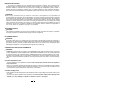
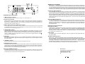
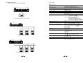
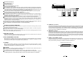
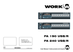
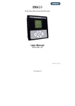
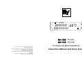
R
R
MA-1212
Professional Mixer/Amplifier
MASTER
INPUT5
0
INPUT6
10
0
INPUT7
10
0
INPUT8
10
0
INPUT9
10
0
INPUT10
10
0
BASS
10
10
TREBLE
+10
10
+10
0
Mute
INPUT1
INPUT2
INPUT3
INPUT4
AUX1
AUX2
10
MONITOR
OUTPUT
OFF
ON
0
10
0
10
0
10
0
10
0
10
0
10
POWER
MA-1206 60 watt
MA-1212 120 watt
U.S.A and Canada only. For customer orders, contact Customer Service at:
800/392-3497 Fax:800/955-6831
Europe, Afuica, and Middle East only. For customer orders, contact customer Service at:
+ 49 9427-706 0 Fax: + 49 9421-706 265
Other International locations. For customer orders, contact Customer Service at:
+ 1 952 884-4051 Fax: + 1 952 887-9212
For warranty repair or service information, contact the Service Repair department at:
800/685-2606
For technical assistance, contact Technical Support at: 886/78 AUDIO
Specifications subject to change without notice.
Professional Mixer/Amplifiers
Instruction Manual and Users Guide
INSTALLATION NOTES
At all times, the amplifier has to be operated under appropriate conditions. This includes that the
operation location provided sufficient ventilation and the device is not exposed to direct sunlight or
the direct radiation or reflection from any heat source. Installing the loudspeaker systems choose a
location that gets not affected by extreme and / or constant vibration or other mechanical oscillation.
also make sure that the speakers are installed at locations that are free from dust and / or moisture.
CAUTION
We strongly recommend that you leave the connection of the appliance to the qualified and
experienced service technician who is specialized in connecting electrical and electronically equipment.
Do not take the risk of Electro-shock or shock hazard. To reduce the risk of Electro-shock, all connections
have to be accomplished before it is permissible to connect the amplifier to the main supply, Before
carried out correctly and that no short-circuit connecting the appliance to the mains supply, once again
make certain that all connections are existing. The overall sound reinforcement installation has to be in
accordance to the laws, regulations, standards, and guidelines that are relevant and applicable in
the country where the equipment is going to be operated.
AC POWER SUPPLY
CAUTION
This equipment operates from a power source that does not apply more than 244 VAC(r.m.s) between
the supply conductors or between either supply conductor and ground.
DC POWER SUPPLY
CAUTION
A 24V DC power source (i.e. a battery) has to be connected to the terminals (13) that are covered by a
protective lid. To reduce the risk of dropping voltage to a minimum and to eliminate the danger of damaging
the battery cables by thermal overload, these cables have to be at least 2.5mm in diameter, each
Switching the amplifier on or off is performed through the power switch (6).
CONNECTING THE OUTPUT TERMINALS
CAUTION
TERMINALS marked with the symbol are HAZARDOUS LIVE and the external wiring connected
to these TERMINALS requires installation by an INSTRUCTED PERSON or the use of ready-made lead
or cords to avoid the risk of electrical shock, never touch the bare conductors leading to the output
terminals of the amplifier when it is in operation. Under figures, show the possible connections of the
" OUTPUT" speaker terminals accessible by removing the protective cover. Bear in mind the following
rules:
Constant impedance lines
The total impedance of the speakers connected must correspond to that selected on the amplifier's
output terminals.
The sum of the power capacities of the speakers must be no lower than the amplifier's power capacity.
The length of the connecting cables must be as possible; in any case, the longer the distance to be
covered and the greater must be the cross-section of the cables.
Constant voltage lines
Each speaker must be equipped with a line transformer with an input voltage equal to that of the line (25,
70, 100V).
The sum of the power capacities of the speakers must not exceed the output power capacity of the
amplifier (i.e. total wattage of speakers installed in zones 1 through 5).
1
SAFETY PRECAUTIONS
1. Please read the notes proceeded by the symbol
safety information.
with special attention, as they provide important
2. The power supply voltage of the amplifier has a sufficiently high value to involve the risk of electrical
shock; therefore, never install, connect, or disconnect the equipment with the power supply
switched on.
3. The metal parts of the equipment are earthed by means of the power cable. If the power socket
used to Supply power does not have an earth connection, call a qualified electrician who will earth
the equipment by means of the terminal.
4. Make sure that the power supply cable of the equipment cannot be trodden on or crushed by objects,
To ensure that the cable is not damaged.
5. To prevent the risk of electric shock, never open the equipment: there are no parts inside that the
user can use.
6. Make sure that no objects or liquids can get into the speaker, as this could cause a short circuit.
7. Never attempt to make any repairs that are not described in this manual. Contact your authorized
service centers or highly qualified personnel when:
The equipment does not function (or functions in an abnormal way).
The power supply cable has been seriously damaged.
Objects or liquids have got into the equipment.
The equipment has been subject to heavy impact.
8. If the equipment is not to be used for long periods of time, switch it off and disconnect the power
supply cable.
9. If the equipment gives off any strange oder or smoke, switch it off immediately and disconnect the
power from the supply cable.
PRECAUTIONS
Do not obstruct the ventilation grilles of the equipment.
Avoid having the amplifier worked on overload for a long time.
Fully tighten the screw terminals for speakers in order to ensure a safe contact.
Do not force command parts (buttons, controls, etc.).
When cleaning external parts, do not use thinners, spirits, or any other volatile substances.
No naked flame sources, such as lighted candles, should be placed on the apparatus.
DESCRIPTION
The amplifiers in the MA-1212 series have been expressly designed for transmitting announcements
through all PA sound systems. They incorporate the following functions:
10 combination jack (XLR and 6.3mm) inputs, line/micro switchable sensitivity with excludable
24V dc phantom supply.
2 stereo RCA input, four stage sensitivity selectable.
600 auxiliary signal(Aux. Paging) input.
1 "PRE OUT" output.
1 "MONITOR OUTPUT" and "1W/8 " slave output for monitor music signal.
1 "MAIN IN" input.
Input 1 priority on the other inputs with vocal activation.
Input 1, 2, 3, 4 priority on the other inputs, activation with contact.
Outputs for speakers with constant impedance (4 ohm) and constant voltage (25-70-100 V).
Treble and bass controls.
Protection against short-circuiting between output terminals.
Direct current supply 24 Vdc.
2
R
MA-1212
9
8
BASS
TREBLE
7
WARRANTY STATEMENT
Electro-Voice products are guaranteed against malfunction due to defects in materials or
workmanship for a specified period, as noted in the individual product-line statement(s) below,
or in the individual product data sheet or owner's manual beginning with the data of original
purchase. If such malfunction occurs during the specified period, the product will be repaired
or replaced (at our discretion) without charge. The product will be returned to the customer prepaid.
Professional Mixer/Amplifier
MASTER
INPUT5
0
INPUT6
10
0
INPUT7
10
0
INPUT8
10
0
INPUT9
10
0
INPUT10
10
0
10
10
+10
10
+10
0
Mute
INPUT1
INPUT2
INPUT3
INPUT4
AUX1
AUX2
10
MONITOR
OUTPUT
OFF
ON
0
10
0
10
0
10
0
10
0
10
0
10
POWER
1
2
3
4
5
6
CONTROL AND FUNCTIONS
1. "Mute" function switch
This switch lets you turn the "Voice Priority" on or off of input 1 (1).
Exclusions and Limitations
The Limited Warranty does not apply to:(a) exterior finish or appearance; (b) certain specific
items described in the individual product-line statements below, or in the individual product
sheet or owner's manual; (c) malfunction resulting from use or operation of the product other
than as specified in the product data sheet or owner's manual;(d) malfunction resulting from
misuse or abuse of the product; or (e) malfunction occurring at any time after repairs have been
made to the product by anyone other than Electro-Voice Service or any of its authorized
representatives.
Obtaining Warranty Service
2. Input level controls
These controls let you individually set the volume of the sound source that are connected to
the "INPUT 1 ~ INPUT 10","AUX 1" and "AUX 2". Turning a control clockwise increases the
volume of the corresponding source. We recommend to leave the controls of momentarily not
used inputs their minimal setting "0".
3. Music signal monitor output level control
The control lets you individually set the volume of the sound output that are connected to
the "MONITOR OUTPUT" (4) and "1W/8 "(25).Turning controls clockwise increase the
volume of the corresponding source.
4. "MONITOR OUTPUT"
This allows signal output of the "AUX1","AUX2","CASSETTE" and "TUNER" input mixing. It can be
used to control an audio appliance with input impedance over 600 ohms (e.g. Earphone or an
additional amplifier etc.) The output signal is controlled only by the volume controls of the "AUX 1",
"AUX 2", "TUNER" and music signal level control (3). This function is toggle switch the "1W/8 "
(25) additional loudspeaker.
5. Indicator
When switch the amplifier's power on. The "PL" indicator lights. When the amplifier's output overload
the "OVER LOAD" indicator lights and interrupt output. For equipment life, you have to adjust the volume
at a lower setting.
6. "POWER" switch
Using the POWER switch lets you turn the main power on or off.
To obtain warranty service, a customer must deliver the product to Electro-Voice Service
or to any of its authorized service representatives, together with proof of purchase of the product
in the form of a bill of sale or receipted invoice. A list of authorized service representatives is
available from Elector-Voice
Service at 12000 Portland Avenue. Burnsville, Mn55337.
Ph: (887)863-4166.
Incidental and Consequential
Damages Excluded
Product repair or replacement and return to the customer are the only remedies provided
to the customer. Electro-Voice
shall not be liable for any incidental or consequential damages
including, without limitation, injury to persons or property or loss of use. Some states do not
allow the exclusion or limitation of incidental or consequential damages, so the above limitation
or exclusion may not apply to you.
Other rights
This warranty gives you specific legal rights , and you may also have other rights which vary
from state to state.
Speakers and Electronics
Electro-Voice Speakers and Speaker Systems are guaranteed against malfunction due to
defects in Materials or workmanship for a period of five (5) years from the date of original purchase.
The Limited Warranty does not apply to burned voice coils or malfunctions such as cone and/or
coil damage resulting from improperly designed enclosures. Electro-Voice active electronics
associated with the speaker systems are guaranteed for three (3) years from the date of original
purchase. Additional details are Included in the Uniform Warranty statement.
7. MASTER volume control
The setting of this control determines the output that is present at the loudspeaker OUTPUT. We
recommend to generally adjust the MASTER and the input level controls at mediocre positions.
extreme setting, where the MASTER is set to maximum output and the input controls nearly set to
their minimum or vice versa are not recommendable.
8.Common TREBLE-control
Clockwise this control enhances the high frequency reproduction, while turning it counter
clockwise attenuates the treble frequencies. If the control is set to its center position, the
overall frequency response is not being altered.
Electro Voice
12000 Portland Avenue South, Burnsville , MN 55337
Phone: 952/884-4051, Fax:952/884-0043
www.electrovoice.com
C
3
Telex Communications, Inc. 10/2001
12
9.Common BASS-control
Clockwise this control enhances the low frequency reproduction, while turning it counter
clockwise attenuates the bass frequencies. If the control is set to its center position, the
overall frequency response is not being altered.
Example of possible connections
25
26
24
20
21
22
23
19
Microphone
N
Microphone stand
AM/FM tuner
.
o
of N
rt
nd
TU
d
L Lis
RTV Rheinla te
,I
nc
CD player
RISK OF FIRE-REPLACE
FUSE AS MARKED
CAUTION:
WARNING
NO-OUTDOOR USE
hA
ca
meri
AC 115V~ 60Hz
DC 24V 15A
RATED INPUT 315W
24V
LINE
24V
MIC
LINE
MIC
24V
LINE
MIC
24V
LINE
MIC
24V
LINE
MIC
24V
MIC
LINE OUTPUT
ON
1
OFF
Cassette recorder
2
3
1W / 8W
-
Priority
+
Tel. Paging
T
R
+
INPUT10
G
TEL
VOL.
GND
DC
+
24V 15A
-
COM
4
INPUT9
1234
LINE 115V~ 60Hz
CD player
Speaker
LINE
ELECTRIC SHOCK HAZARD. DO NOT REMOVE COVER.
REFER SERVICING TO QUALIFIED PERSONNEL. SEE
INSTRUCTION MANUAL.
'
AVIS RISQUE DE CHOC ELECTRIQUE-NE
PAS OUVRIR.
DC POWER
25V 70V 100V
AM/FM tuner
LINE
PRE
OUT
L
L
MAIN
IN
R
R
AUX2
T 5A
AUX1
INPUT7
INPUT8
1234
1: for CD Player
2: for AM/FM Radio
3: for Cassette Player
4: for AUX IN
24V
LINE
INPUT6
24V
LINE
INPUT5
24V
LINE
24V
MIC
MIC
MIC
MIC
INPUT4
INPUT3
INPUT2
INPUT1
MADE IN CHINA
Cassette player
.
,I
nc
o
of N
rt
nd
TU
L Lis
RTV Rheinla te
d
N
Contact
"VOICE PRIORITY"
RISK OF FIRE-REPLACE
FUSE AS MARKED
CAUTION:
WARNING
NO-OUTDOOR USE
hA
ca
meri
ELECTRIC SHOCK HAZARD. DO NOT REMOVE COVER.
REFER SERVICING TO QUALIFIED PERSONNEL. SEE
INSTRUCTION MANUAL.
'
AVIS RISQUE DE CHOC ELECTRIQUE-NE
PAS OUVRIR.
LINE
24V
10
LINE
MIC
24V
LINE
MIC
24V
LINE
MIC
24V
LINE
MIC
24V
LINE
MIC
24V
MIC
DC POWER
AC 115V~ 60Hz
DC 24V 15A
RATED INPUT 315W
1
OFF
2
3
1W / 8W
-
Priority
+
Tel. Paging
T
R
G
+
INPUT10
TEL
VOL.
DC
+
24V 15A
-
COM
4
25V 70V 100V
INPUT9
1234
LINE 115V~ 60Hz
GND
12
13
14
15
16
17
18
CONTROL AND FUNCTIONS
10. Main cord connector
LINE OUTPUT
ON
11
LINE
PRE
OUT
L
L
MAIN
IN
R
R
AUX2
T 5A
AUX1
INPUT7
INPUT8
1234
1: for CD Player
2: for AM/FM Radio
3: for Cassette Player
4: for AUX IN
24V
MIC
LINE
INPUT6
24V
LINE
MIC
This connector is meant for the connection of the supplied mains cord.
INPUT5
24V
MIC
LINE
24V
MIC
11. AC fuse
The fuse protecting currents supplies circuits of the equipment. The fuse can only be changed, in
the event of a fault or changing the supply voltage, by an EV service center.
INPUT4
INPUT3
MADE IN CHINA
INPUT2
INPUT1
12. "GND" screw
In case the used mains outlet does not provide a ground conductor, this screw offers the
possibility to amplifier metal parts. Nevertheless , you should leave this procedure to the
experienced, qualified electrician.
Mains
Equalizer
24V
Battery
Power amplifier
13. Terminals for the DC battery supply
These two terminals allow the connection of an external 24V DC power supply (e.g.a 24V
battery). In this way continuous of the amplifier is maintained even during a power outage,
since it is automatically switch to the DC power source.
DC24V 10A
+
Horn speaker
Sound column
-
+
COM
4W
24Vdc
11
4
25V 70V 100V
14. Output terminals
Technical data
These 5 terminals allow connecting speakers.
Amplifier section
Type
DC24V 10A
+
-
4W
COM
Output power capacity
25V 70V 100V
Nominal power capacity with supply at 24Vdc
Frequency response
Total harmonic distortion
Signal / noise ratio
+
-
Inputs / sensitivity-impedance
4 ohm
Connecting the speakers to 4 ohm output
DC24V 10A
+
-
Outputs for speakers / Ohms
Outputs for speakers / Volts
COM
4W
25V 70V 100V
0
25V
0
25V
0
25V
Connecting the speakers to 25V output
DC24V 10A
+
-
COM
4W
60W-Mono-tabletop (MA-1206 series)
120W-Mono-tabletop (MA-1212 series)
Nominal: 60W- maximum:90W (MA-1206 series)
Nominal: 120W- maximum:180W(MA-1212 series)
45W(MA-1206 series)
90W(MA-1212 series)
50-15,000Hz ( 3dB)
1%(1KHz-nominal power capacity)
INPUT 1-10, AUX1,2: >45dB
MAIN IN: >55dB
INPUT 1-10 / XLR and 6.3mm combination socket / balanced
Micro: -60dB (1mV)-600
Line: -22dBu (75mV)-47K
AUX1-2 / stereo RCA jack / unbalanced
1: 0dB (1V)-240K (for CD player)
2: -6dB (500mV)-120K (for tuner radio)
3: -10dB (300mV)-75K (for cassette player)
4: -20dB (100mV)-24K (for auxiliary appliance)
MAIN IN / mono RAC jack / 0dB(1V)-10K / unbalanced
4 ohms
25V-70V-100V (10 , 83 , 170 )(MA-1206 series)
25V-70V-100V (5 , 42 , 83 )(MA-1212 series)
Additional outputs / voltage-impedance
PRE OUT / mono RCA jack / 1V-600 / unbalanced
Loudspeaker / on terminal board / 1 watt-8
Monitor output / 6.3mm jack / 1.5V-600 / balanced
Line out / balanced
Output / 1V/ 0dB
Tone controls
Bass 10dB-100Hz
Treble 10dB-10KHz
Controls
13 volume controls for INPUT 1-10, AUX1-2 and tel. paging
1 master volume control
1 treble control
1 bass control
Power supply / Consumption
230 Vac ( 5%)-50Hz / 145W (MA-1206 series)
230 Vac( 5%)-50Hz / 315W (MA-1212 series)
Direct current draw (24V)
5A (MA-1206 series)
10A (MA-1212 series)
Dimensions(L
Weight
480 320 150 mm (18.9" 12.6"
9kg (19.84 Ib) (MA-1206 series)
12kg (24.46 Ib) (MA-1212 series)
H
W)
25V 70V 100V
0
70V
0
70V
0
70V
Connecting the speakers to 70V output
5
10
5.9")
Read these instructions.
Keep these instructions.
Heed all warnings.
Follow all instructions.
Do not use this apparatus near water.
Clean only with a damp cloth.
Do not block any of the ventilation openings. Install in accordance with the manufacturers instructions.
Do not defeat the safety purpose of the grounding-type plug. A grounding type plug has two lades and
a third ground prong. The third prong are provided for your safety. When the provided plug does not fit
your outlet, consult an electrician for replacement of the obsolete outlet.
Protect the power cord from being walked on or pinched particularly at plugs, convenient receptacles,
and the point where they exit from thee apparatus.
Only use attachments/accessories specified by the manufacturer.
The apparatus should be placed on a solid surface with a minimum distance of 1 m from the back or
side plate to the wall and not in the following environments of cases; moist place; under direct radiation
sunlight or other strong heat radiation.
Unplug this apparatus during lightning storms or when unused for long periods of time
Refer all servicing to qualified service personnel. Servicing is required when the apparatus has been
damaged in any way , such as power-supply cord or plug is damaged, liquid has been spilled or
objects have fallen into the apparatus, the apparatus has been exposed to rain or moisture, not
operate normally, or has been dropped.
This handbook is an integral part of the product and must accompany when it is changed, to allow the
new owner to get to know the installation, operating, and safety instructions.
Faulty installation of the amplifier frees EV from all responsibility.
DC24V 10A
+
-
COM
4W
25V 70V 100V
0
100V
0
100V
0
100V
Connecting the speakers to 100V output
15. "PRE OUT" terminal
CAUTION FOR USING POWER LINE
You shall hold plug firmly to avoid the pull-out of power line and risk occurring when you pull
the power line out from AC outlet.
The plug of power line for unit should be pulled out from power outlet to cut down the power
supply, when this unit isn't used for a long period.
Don't force any matter on the power line of this system to avoid the damaging power line and
don't insert the knotted power line into unit.
HANDLING THIS UNIT
Check if the power supply is being shut down, the power line is pulled out from outlet and
other lines connecting this unit are also disconnected.
DON'T DISASSEMBLE THIS UNIT
Servicing-Do not attempt to service the product beyond that described in the operating
instructions, as opening or removing covers may expose you to dangerous voltages. All other
servicing should be referred to qualified service personnel.
This terminal output the mixed audio signals of all sources that are connected to the amplifier
Inputs and can be utilized to feed an external power amplifier, a signal processor (e.g.a equalizer)
or any other external appliance. The unbalanced signal is affected by the individual input
controls. Before using the PRE OUT you have to remove the bridging-strip between this
binding post and the "MAIN IN" terminal(16).
16. "MAIN IN" terminal
After removing bridging-strip between the "PRE OUT" and the "MAIN IN" terminals you can
include an external signal processor (e.g an equalizer) in the audio-chain between the
pre-amplifier and the power output stage of the power amplifier. This opportunity provides
a proper solution whenever shaping or improving the audio signal is necessary (adjust delay
times, equalizing, eliminating the larseneffect, ect.) The input is unbalance, which affected
by the tone control and the master volume control.
17. "AUX 1" and "AUX 2" inputs
These two RCA-type connectors let you connect the two channels of an external high-level
unbalanced signal source. Such as an AM/FM tuner, a cassette deck, a CD player, etc..
use input sensitivity switch(20). Suitable for different appliances.
CLEANING
When the unit needs a cleaning, you can blow off dust from the unit with a blower or clean
rag etc. Don't use solvents such as benzol, thinner, alcohol or other fluids with very strong
volatility and flammability for cleaning the unit body.
Unbalanced signal (channel Lo R)
Earth
RCA plug
! CAUTION
Don't touch the screw around the ventilation holes in the bottom board. When heat sink is
working, the screw's temperature will rise higher.
If connecting interference takes place in source circuit, THD will be more than 10%.
To prevent the risk of fire or electrical shock, the apparatus shall not be exposed to dripping
or splashing and that no objects filled with liquids, such as vases, shall be placed on the apparatus.
9
6
18. "INPUT 1 ~ INPUT 10" Inputs
These ten balanced/unbalanced combination type jack (XLR and 6.3mm) input, Meant for
the connection of-condenser type microphone that accept 24V phantom power, dynamic
microphone (30-600ohms) or a high level sound source (e.g AM/FM tuner, cassette desk,
CD player, ect.) In case you are using , it is necessary to use the switch (20).
20. Input sensitivity switch (AUX1 , AUX2)
By turning switch onto the "1" position, the "AUX 1" , "AUX 2" input suitable for connected to CD
player signal output. By turning this switch onto the "2" position, the "AUX1","AUX2" input suitable
for connected to AM/FM radio signal output. By turning this switch onto the"3" position, the "AUX1"
"AUX2" input suitable for connected to desktop cassette player signal output. By turning this switch
onto the "4" position, the "AUX1", "AUX2" input suitable for connected to high-leven signal
output.
21. TEL. Paging input level control
2
1
3
This control let you set the volume of the sound source that is connected to the "Tel. Paging" (23)
turning control clockwise can increase the volume of the corresponding source. We recommend
to leave the control at it's minimum setting "0" when it is not used.
22. LINE OUTPUT CONNECTOR
Balanced microphone
3-pin XLR plug (seen from welded side)
2
1
3
Unbalanced microphone
3-pin XLR plug (seen from welded side)
This XLR output mixed audio signals of all sources that can be utilized to feed an external
power amplifier or an other external appliance.
23. Input "TEL.Paging"
It lets you connect to an auxiliary signal (600 ohms). The input features the "Voice Priority" function
, which overrides all other input signals, once an auxiliary message is sent. If you want to have this
function disabled forever, please contact an EV SERVICE CENTER.
24. "Priority" terminal
When short-circuiting these terminals (i.e means of using an electrical switch). The audio signals
coming form "AUX1", "AUX2","CASSETTE" and "TUNER" are attenuate, while the signals
coming form "IN1" , "IN2" and "IN4" are gaining priority.
Stereo jack
Balanced microphone
1W / 8W
-
+
Priority
Aux. Paging
T
R
G
Mono jack
Unbalanced microphone
Auxiliary conctat
25. Output terminal for auxiliary loudspeaker
Note
Connecting unbalance microphones to the appliance when the phantom is switched on could
lead to severe damage on the microphones and is therefore not permissible. It is absolutely
mandatory to perform any plugging or unplugging of microphone cables with the phantom
power turned off. Also make sure that the phantom power is turned off when utilizing microphones
that are not meant to be operated with phantom power, The voltage that is present on pin2
and pin3 of the XLR-connector could lead to severe damages on the microphones. When in
doubt, contact your dealer before you perform any connections.
The terminal is meant for the connection of a small external loudspeaker that gets driven by an internal
auxiliary power amplifier, providing a nominal output 1 watt. Only the mixed audio signal coming from
"AUX1" , "AUX2" "CASSETTE" and "TUNER" are included in the output signal. In addition, the
output signal is controlled only by the volume controls of the "AUX1","AUX2","TUNTER" and music
signal level control(4). This function is toggle switch the "MONITOR OUTPUT"(4) additional loudspeaker.
1W / 8W
-
7
Priority
Aux. Paging
T
+
19. "INPUT 1 ~ INPUT 10" Inputs sensitivity and XLR phantom 24V switch
By turning this switches onto the "LINE" position the input can be connected to an audio source
with high level signal output. By turning these switches onto the "MIC" position, the input can be
connected to a dynamic microphone with low impedance. By turning these switch onto "24V"
position, connects the 24V phantom supply on XLR of pin2 and pin3 of inputs, necessary to
operate condenser type microphone which require this type of external supply. It is recommended
to use this switch with the general volume set on minimum.
+
1W 8 ohm
26. DC switch
-
This switch lets you turn the battery supply on or off.
8
R
G