1
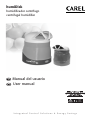
humiDisk humidificador centrífugo centrifugal humidifier Manual del usuario User manual NO POWER & SIGNAL CABLES TOGETHER READ CAREFULLY IN THE TEXT! Integrated Control Solutions & Energy Savings Warning L’installazione del prodotto deve obbligatoriamente comprendere la connessione di messa a terra, usando l’apposito morsetto giallo-verde in morsettiera. Non utilizzare il neutro come connessione a terra. The product must be installed with the earthconnected, using the special yellow-green terminal on the terminal block. Do not use the neutral for the earth connection. Le produit doit être installé avec la connexion terre branchée, en utilisant la signalisation et les bornes spécifiques (jaune/vert) à la mise à la terre. Ne pas utiliser le neutre comme mise à la terre. Das Produkt muss geerdet werden. Verwenden Sie hierfür den gelb-grün Anschluss an der Klemmleiste. Verwenden Sie nicht den Null-Leiter für die Erdung. La instalación del producto debe obligatoriamente incluir la conexión de la toma de tierra, utilizando el borne amarillo/verde del regletero. No utilizar el neutro como conexión a tierra. User manual IMPORTANT WARNINGS BEFORE INSTALLING OR HANDLING THE APPLIANCE PLEASE CAREFULLY READ AND FOLLOW THE INSTRUCTIONS DESCRIBED IN THIS MANUAL. ENGLISH This device has been designed to humidify directly into the room. The installation, operation and maintenance operations must be performed in compliance with the instructions provided in this manual. All other uses and modifications made to the appliance that are not authorised by CAREL S.p.A. are considered incorrect. The environmental conditions must comply with the specified values. Disconnect the humidifier from the mains power supply before accessing any internal parts. The unit must be installed according to the standards in force. Liability for injury or damage caused by the incorrect use of the appliance lies exclusively with the user. Please note that the unit contains live electrical devices. All service and/or maintenance operations must be performed by specialist and qualified personnel who are aware of the necessary precautions. 2. 3. 4. 5. 4 Disposing of the product: the product is made up of metal parts and plastic parts. In reference to European Union directive 2002/96/EC issued on 27 January 2003 and the related national legislation, please note that: 1. WEEE cannot be disposed of as municipal waste and such waste must be collected and disposed of separately; The public or private waste collection systems defined by local legislation must be used. In addition, the equipment can be returned to the distributor at the end of its working life when buying new equipment. The equipment may contain hazardous substances: the improper use or incorrect disposal of such may have negative effects on human health and on the environment; The symbol (crossed-out wheeled bin) shown on the product or on the packaging and on the instruction sheet indicates that the equipment has been introduced onto the market after 13 August 2005 and that it must be disposed of separately; In the event of illegal disposal of electrical and electronic waste, the penalties are specified by local waste disposal legislation. humiDisk - +030222022 - rel. 2.1 - 01.03.2012 Contents 1. INTRODUCTION 7 1. INSTALLATION ENGLISH 1.1 General safety instructions ..................................................................................................................7 1.2 Applications.............................................................................................................................................7 1.3 humiDisk .................................................................................................................................................7 1.4 Electrical panels for humiDisk65 ........................................................................................................7 1.5 Humidistat and humidity probes .......................................................................................................8 1.6 Accessores for humiDisk65 ...................................................................................................................................................8 1.7 Description of the components .........................................................................................................8 9 2.1 Material supplied ...................................................................................................................................9 2.2 Preliminary operations .........................................................................................................................9 2.3 Positioning ..............................................................................................................................................10 2.4 Wall mounting .......................................................................................................................................10 2.5 Hanging installation ..............................................................................................................................11 2.6 Electrical connections ...........................................................................................................................12 2.7 Water connections ................................................................................................................................13 2.8 Final operations .....................................................................................................................................14 3. STARTING, CONTROL AND STOPPING 15 3.1 Preliminary checks.................................................................................................................................15 3.2 Starting.....................................................................................................................................................15 3.3 Stopping ..................................................................................................................................................15 4. ELECTRONIC CONTROLLER FOR HUMIDISK65 16 4.1 Electronic board .....................................................................................................................................16 4.2 Dip-switch ...............................................................................................................................................16 4.3 Adjusting the humidification capacity...............................................................................................16 4.4 Washing/emptying cycle .....................................................................................................................16 4.5 Washing/emptying cycle using CAREL electrical panels ..............................................................16 5. ANTIFREEZE DEVICE FOR HUMIDISK65 17 5.1 Assembly .................................................................................................................................................17 6. MAINTENANCE 18 6.1 Cleaning the air filter.............................................................................................................................18 6.2 Inspecting and cleaning the drain siphon .......................................................................................19 6.3 Inspecting and cleaning the fill solenoid valve ...............................................................................19 6.4 Checking the washing/emptying cycle for humiDisk65...................................................................................19 7. STORAGE 20 7.1 Checks to be performed before and after an extended period of inactivity ............................20 7.2 Disposing of the product .....................................................................................................................20 8. OPTIONAL CAREL ELECTRICAL PANELS 21 8.1 Electrical panel UCQ065D100 for the control of one centrifugal humidifier, code UC0650D000 or UC0650D100 .................................................................................................................21 8.2 Electrical panel UCQ065D200 for the control of two centrifugal humidifiers, code UC0650D000 or UC0650D100 umidificatori centrifughi UC0650D000 o UC0650D100. .........22 humiDisk - +030222022 - rel. 2.1 - 01.03.2012 5 9. HUMIDISTAT DN33Z9HR20 ON ELECTRICAL PANELS UCQ065D100 AND UCQ065D200 24 9.1 Setting the fundamental parameters ................................................................................................25 9.2 Alarms and troubleshooting ...............................................................................................................25 10. DIMENSIONS AND WEIGHTS 26 11.TECHNICAL SPECIFICATIONS 26 ENGLISH 11.1 Table of technical specifications for humiDisk10 ....................................................................................26 11.2 Table of technical specifications for humiDisk65 ...................................................................................26 11.3 Electrical specifications of electrical panels UCQ065D100 .......................................................27 and UCQ065D200 .......................................................................................................................................27 11.4 Technical specifications of the CAREL DN33Z9HR20 humidistat .............................................27 11.5 Technical specifications of the UCHUMM0000 mechanical humidistat .................................27 11.6 List of spare parts for humiDisk10 ................................................................................................................28 11.7 List of spare parts for humiDisk65................................................................................................................29 12. TROUBLESHOOTING 30 12.1 The humidifier won’t start .................................................................................................................30 12.2 Air comes out of the distributor, but not atomised water .........................................................30 12.3 The humidifier continuously drains water .....................................................................................30 6 humiDisk - +030222022 - rel. 2.1 - 01.03.2012 1. INTRODUCTION humiDisk is an air humidifier and operates on the principle of atomising water by centrifugal force. The appliance can operate either on drinking or demineralised water. The appliance s supplied in two versions: humiDisk10 with production of around 1 kg/h of atomised water. humiDisk65 with production of around 6.5 kg/h of atomised water. humiDisk10 is a simple product that can be controlled by an external switch or humidistat. To prevent stagnant water from depositing inside the appliance and, consequently, the proliferation of bacteria that is dangerous to the health, automatic supply tank emptying cycles are activated. The appliance can work at temperature 1 °C. ENGLISH The operation of the humiDisk65 is controlled by an electronic board which, besides managing the normal operations of the appliance, also ensures regular automatic washing cycles of the supply tank, so as to prevent stagnant water from depositing inside the appliance and, consequently, the proliferation of bacteria that is dangerous to the health. humiDisk65 code UC0650D000 can operate at temperatures down to around 1°C. The antifreeze device (code UCKH70W000), an accessory available upon request with the UC0650D000, allows humiDisk65 to operate at temperatures down to-2°C. humiDisk65 code UC0650D100 is however already fitted as standard with the antifreeze device. 1.1 General safety instructions Caution! Before carrying out any kind of repairs on the appliance, the following precautions should always be observed to avoid unwanted problems. Consequently, read the following instruction manual before proceeding. • The appliance must be connected to an electrical system in compliance with the local standards in force, via an electrical panel containing all the control and safety devices. • Before carrying out any work on the appliance, always remember to disconnect the power supply using the main switch on the control panel. • When carrying out any work on the appliance, make sure, once the work has been completed, and before starting again, that no tools of any kind have been left inside the appliance. • Installation and maintenance of the appliance must be performed by expert and qualified personnel, capable of carrying out the work according to the instructions provided in this manual. • This appliance has been designed to humidify the air, and consequently must not be used for any other purposes. • Any uses other than those described in this manual are considered improper, potentially damaging and dangerous. • Carefully keep these instructions for future reference. 1.2 Applications humiDisk is particularly suitable for use in: • cold rooms and cold stores containing products such as fruit and vegetables, where a lack of humidity leads to a loss in weight and the deterioration of the product; • printing industries, where the correct humidity must be maintained to avoid variations in the size of the paper and consequent printing errors; • textile industries, where the correct humidity must be maintained according to the production process and the type of textile being processed, and at the same time disposing of the heat produced by the looms. These represent just some of the possible applications for centrifugal humidifiers. 1.3 humiDisk code UC0100D000 UC01001010 UC0650D000 UC06501010 UC0650D100 description water spray humidifier - 1.0 kg/h - 230 V 50 Hz water spray humidifier - 1.2 kg/h - 110 V 60 Hz water spray humidifier - 6.5 kg/h - 230 V 50 Hz water spray humidifier - 6.5 kg/h - 110 V 60 Hz water spray humidifier - 6.5 kg/h - with antifreeze heater 230 V 50 Hz Tab. 1.a 1.4 Electrical panels for humiDisk65 code UCQ065D100 description electrical panel for one 6.5 kg/h centrifugal humidifier UCQ065D200 electrical panel for two 6.5 kg/h centrifugal humidifiers humiDisk - +030222022 - rel. 2.1 - 01.03.2012 notes • for UC0650D000 and UC0650D100 only • with electronic humidistat, without humidity probe • for UC0650D000 and UC0650D100 only • with electronic humidistat, without humidity probe Tab. 1.b 7 1.5 Humidistat and humidity probes code description UCHUMM0000 mechanical room humidistat 20 to 90% RH notes Tab. 1.d Room probes (humiDisk65 only) code description ASWH100000 ASWC110000 ASWC111000 notes humidity room probe 10 to 90% RH room temperature-humidity probe 0 to 50 °C 10 to 90% RH room temperature (NTC res.) humidity probe 0 to 50 °C 10 to 90% RH to be used only with electrical panels code UCQ065D100 and UCQ065D200. Tab. 1.e ENGLISH Industrial environments (humiDisk6 only 5) code description ASPC110000 ASPC230000 notes room temperature-humidity probe 0 to 50 °C 10 to 90% RH room temperature-humidity probe -10 to 70 °C 0 to 100% RH to be used only with electrical panels code UCQ065D100 and UCQ065D200 Tab. 1.f 1.6 Accessores for humiDisk65 code description UCKH70W000 70 W heater notes only for UC0650D000 Tab. 1.c 1.7 Description of the components humiDisk10 Key: 1. diffuser 2. motor 3. atomising disk 4. cone with fan 5. drain siphon 6. main body 7. air filter 1 2 3 4 5 6 7 Fig. 1.a humiDisk65 Key: 1. air filter 2. drain siphon 3. cone with fan 4. motor 5. diffuser 6. toothed ring 7. atomising disk 8. main body 5 4 7 6 3 2 1 8 Fig. 1.b 8 humiDisk - +030222022 - rel. 2.1 - 01.03.2012 1. INSTALLATION 2.1 Material supplied The following materials are supplied as standard with the appliance. Check that all the material listed below is included in the packaging before starting work. For humiDisk10 • 1 humiDisk10 model humidifier; • 1 technical installation manual (this manual); • 3 brackets for hanging installation. ENGLISH For humiDisk65 The following materials are supplied as standard with the appliance. Check that all the material listed below is included in the packaging before starting work. • 1 humiDisk65 model humidifier; • 1 technical installation manual (this manual); • 4 wall plugs with screws (for wall mounting); • 1 bracket for wall-mounting; • 3 brackets for hanging installation; • 1 M6x20 hexagonal safety screw; • 1 washer dia. 6x2; • 1 water supply hose l=1.5 m, with G ¾ threaded fittings; • 1 water drain hose l=1.5 m ID 10; • 3 wiring clamps. 2.2 Preliminary operations To make the humiDisk10 and humiDisk65 operative, the following are required: • mains power supply, 230V, 50Hz, with an earth connection and protection devices • water supply connection • water drain connection. C D Note: Installation must comply with the safety requirements of the local standards in force. Then make sure that all the necessary connections to make the appliance operate properly have been correctly prepared. B For the humiDisk10 all the connections, both electrical and water, are located at the rear, as shown in Fig 2.a. The operations listed below should be completed before starting actual installation. With reference to Fig. 2.a: • connect the water drain hose A, not supplied as standard but available on order, code UCKTS00000, to the drain elbow B; • connect end C with the elbow of the water supply hose, not supplied as standard but available on order codeUCKTA00000, to the fill solenoid valve D. The above-mentioned operations can in any case also be carried out with the unit installed. A Fig. 2.a For the humiDisk65 all the connections, both electrical and water, are also located at the rear, as shown in Fig 2.b. The operations listed below should be completed before starting actual installation. With reference to Fig. 2.b: • connect the water drain hose A, supplied, to the drain elbow B; • connect end C with the elbow of the water supply hose, supplied, to the fill solenoid valve D. The above-mentioned operations can in any case also be carried out with the unit installed. D B C A Fig. 2.b humiDisk - +030222022 - rel. 2.1 - 01.03.2012 9 2.3 Positioning Note: the humidisk must be installed in a horizontal position, with the air filter facing downwards, raised above the ground, as shown in figures 2.c, 2.d, 2.e. Any other position will compromise the correct operation of the appliance. To allow maintenance to be carried out where necessary and for the correct operation of the appliance, the minimum suggested distances must be maintained when positioning the humidifier. Choose, depending on the type of installation adopted, the most suitable position for humidifying the room. Do not position the humidifier in a confined space to avoid drawing in saturated air through the filter, and thus wetting it. ENGLISH humidifier humiDisk10 Distance (m) humiDisk65 A B C D 2 0,5 1.5 0,5 3 1 1.5 0.5 Tab. 2.a B B B A D A D C Fig. 2.c C C Fig. 2.d Fig. 2.e 2.4 Wall mounting humiDisk10 To install the humidifier on the wall, use the optional bracket shown in Fig. 2.f and the screws supplied. The bracket can be used as a template to mark the holes on the wall, as shown in Fig. 2.g. Maintain the distances indicated in paragraph 2.3, and make sure that the bracket is level before drilling the holes. Make sure that the wall can support the appliance in normal operating conditions. • Drill three 8 mm dia. holes, 45 mm deep, in the wall as shown in Fig. 2.g; • clean the inside of the holes; • insert the three screw anchors while keeping the two expansion tabs vertical; • Tighten (not fully) two of the screws fastening the humiDisk10 to the bracket, as shown in Fig. 2.h. • Rotate the unit until the two other holes are lined up: the hoses and the wires must run between the humidifier and the bracket, in the special groove. • Tighten the last two screws, then fully tighten all four screws. • Make sure the installation is secure. 100 mm 80 mm Fig. 2.f Fig. 2.g 10 Fig. 2.h humiDisk - +030222022 - rel. 2.1 - 01.03.2012 humiDisk65 To install the humidifier on the wall, use the bracket and the screws supplied. The bracket can be used as a template to mark the holes on the wall. Maintain the distances indicated in paragraph 2.3, and make sure that the bracket is level before drilling the holes. Make sure that the wall can support the appliance in normal operating conditions. • Drill four 8 mm dia. holes, 45 mm deep, in the wall as shown in Fig. 2.i; • clean the inside of the holes; • insert the four screw anchors while keeping the two expansion tabs vertical; • fasten the bracket. The bracket must be fitted as shown in Fig. 2.l. ENGLISH Once the bracket has been fastened to the wall with the four screws, carry out the following operations, as shown in Fig. 2.m: • Lift the appliance and tilt it slightly towards the wall. • Move the appliance until the brackets fit into place. • Let the appliance roll down, while guiding it, to the horizontal position: at this point the brackets should be perfectly coupled and interlocked. • Insert the safety screw supplied that joins the two brackets and that prevents the appliance from accidentally becoming dislodged. 120 mm 120 mm Fig. 2.i Fig. 2.l Fig. 2.m 2.5 Hanging installation Hanging installation is performed using the standard brackets supplied. Three supporting chains must be prepared for hanging the appliance. The chains must hang down as straight as possible and be attached to hooks that can bear the weight of the appliance (see Fig. 2.n and paragraph 10). Use metal, possibly steel chains, and at any rate material that is not affected by humidity. Maintain the minimum distances indicated in Tab. 2.a. For the humiDisk10 use the brackets supplied, hooking one side onto the holes at the bottom and the other to the chains hanging from above. For the humiDisk65 remove the rear bracket A, for wall mounting, as shown in Fig. 2.p, by unscrewing the four screws V. Fig. 2.n Now there should be five (5) screws available (4 screws removed from the plate A, and 1 safety screw, supplied) each with its own washer. Replace 2 screws in the holes F indicated in Fig. 2.p. Use 3 screws to fit the brackets for hanging installation as shown in Fig. 2.q. The brackets have been designed to allow the removal of the filter, so that normal maintenance operations can be carried out without having to unhook the appliance from the supporting chains. Hook the appliance to the chains and at the same time check that it is in a horizontal position. mm L>12 mm <3 Fig. 2.o Fig. 2.p humiDisk - +030222022 - rel. 2.1 - 01.03.2012 Fig. 2.q 11 2.6 Electrical connections Installation requires the use of an ON/OFF humidistat that controls the operation of the humidifier: in place of this, however, a simple ON/OFF contact can be used, with the only difference that the appliance must be started and stopped manually. This choice however does not in any way influence the installation procedure described below. Important: A device must be installed for isolating the appliance from the power supply, as shown in Fig. Fig. 2.r and 2.s. A 2.5 A slow blow fuse must also be installed for staring the motor. When selecting the switch or the humidistat to be connected to terminals “HH”, check the compatibility of the humidifier power and current input values shown in Tab. 11.a and 11.b on page 26. 2 Key: 1. humidifier motor 2. level switch 3. solenoid valve 4. external humidistat jumper (to be removed) 1 3 A M 2 + % r.H. + 1 A. external ON/OFF humidistat (to be provided by the installer) B. line protector (to be provided by the installer) F N H H 4 B M M L L 230 V, 50/60 Hz V V Fig. 2.r 2.6.1 Wiring diagram, UC65 Key: 1. ON/OFF humidistat (to be provided by the installer) 2. float 3. motor 4. solenoid valve 5. heater (optional) 6. temperature probe 7. electronic board 8. line protector (to be provided by the installer) 2 6 7 + ON UMID 3 4 ELET. CARICO MOTORE M 12 3 LEVEL humiDisk 65 5 ESTERNO 1 + L N % r.H. ENGLISH 2.6.1 Wiring diagram, UC10 8 230 V, 50 Hz Fig. 2.s 12 humiDisk - +030222022 - rel. 2.1 - 01.03.2012 2.6.3 Wiring Important: The flexible cable used for the electric connections must be at least protected by an ordinary PVC sheath and comply with the 227 IEC 53 standards (CENELEC H05VV-F or H05VVH2-F or better). Wiring humiDisk10 (Fig. 2.t): • open the cover of the electrical junction box, located on the rear of the unit, by unscrewing the four screws V; • run the power cable through the cable gland P; • remove terminal block M from the box; • wire the phase to terminal F, the neutral to terminal N and the earth to the terminal marked with the corresponding symbol; • place the terminal block back in the box, sliding the support brackets into the guides G; • close the box. V G Fig. 2.t Wiring humiDisk65 (Fig. 2.u): • Remove the electrical junction box by levering the locking spring C. The box comes down: remove the cover by unscrewing the four screws. In the box there are two cable glands that will be used to pass the power cable and the humidistat cable through to the electronic board; • pass the power cable through the cable gland 1a on the appliance, and then through the cable gland 1b on the junction box. Fasten the neutral and phase (live) wires to the terminals N 230 F on the board and the earth wire to the free terminal inside the box; • in the same way, pass the humidistat wire through the cable gland 2a on the appliance, then through the cable gland 2b on the box and connect it to the UMID terminals of the board; • then use the 2 clamps supplied to secure the two cables that have just been passed through the glands to the existing cables: the clamps should be placed in the position shown by the arrows. Finally, tighten the four bushings on the cable glands. Once the electrical connections have been completed, carefully close the box with its screws, place it back in position, and secure it with the locking spring C. At the end of installation, the inside of the appliance should appear as shown in Fig. 2.u. Fig. 2.u 2.7 Water connections Note: the water connection hoses are supplied as standard only for the humiDisk65, while for the humiDisk10 they are available as options. The installation of the humidifier also requires the water supply and drain hoses to be connected. The hoses, supplied, must be connected to the appliance as shown in Figure 2.v for the humiDisk10 and Figure 2.z for the humiDisk65. The supply hose A, supplied as standard, has a threaded G 3/4 bushing at both ends: connect the elbow to the solenoid valve on the humidisk, connect the free end (straight end) directly to water tap B, or to an extension. A mechanical filter C should be fitted downstream of the tap B, as shown in Figs. 2.v and 2.z. For the water drain, use the plastic hose D, supplied, or a similar hose with an inside diameter of 10 mm. The hose must be installed as shown in Figs. 2.v and 2.z with a minimum slope of 10°, to guarantee the correct drainage of the water. If used, a drain siphon E must be located on the main drain line and not on the drain hose connected to the appliance. Importat: To ensure the correct drainage of the water, make sure that the drain hose runs at a slope and is straight, without any bends or choking. humiDisk - +030222022 - rel. 2.1 - 01.03.2012 13 ENGLISH M P Water connections on the humiDisk10 D ENGLISH E C B <10° A Fig. 2.v Water connections on the humiDisk65 Fig. 2.z 2.8 Final operations Make sure that all the wires are positioned properly inside the appliance as shown in Figs 2.t and 2.u. For the humiDisk65 check that the junction box is properly closed and positioned correctly, and that the spring is tightened. The box must have the surface of the cover resting on the two surface locators, as shown in Fig. 2.w. • Replace the air filter and tighten the three supporting screws; • adjust the direction of the outlets. To do this, loosen the screws that hold the diffuser on top of the appliance; see position 1 in Fig. 1.a for humiDisk10 and position 5 in Fig. 1.b for humiDisk65: at the end of the operation tighten the screw again. • check that the water connections have been carried out correctly. Open the water supply tap and check that there are no leaks along the supply circuit. Fig. 2.w 14 humiDisk - +030222022 - rel. 2.1 - 01.03.2012 3. STARTING, CONTROL AND STOPPING 3.1 Preliminary checks ENGLISH Before starting up the humidifier check that: • all the electrical and water connections have been completed according to the instructions described in this manual; • there are no water leaks in the circuit; • the air filter is fitted; • the water supply tap is open; • the distribution outlets are adjusted in the correct direction. 3.2 Starting 3.2.1 humiDisk10 To start the operation of the humidifier, turn on the main switch. The unit comes on immediately and after a few seconds starts atomising. During operation, make sure the water is not draining continuously. If this is the case, see the possible solutions in par.12. 3.2.2 humiDisk65 To start the operation of the humidifier, turn on the main switch. The appliance will perform a washing cycle lasting about one minute, as described in detail in par. 4.4 Washing/reset cycle. At the end of the cycle, if the humidistat contact is closed, the humidifier starts the motor and starts atomising the water. Important: if the ON/OFF contact is used instead of the humidistat, this must be closed manually to start the appliance, as otherwise it will not start at the end of the washing/reset cycle. During operation check that the water is drained correctly. If necessary, adjust the humidification capacity as per the instructions shown in par. 4.3 Adjusting the humidification capacity. 3.3 Stopping 3.3.1 humiDisk10 To switch the unit off, simply open the main switch. The humidifier will slow down until stopping, while the water contained in the unit runs down into the tank and primes the drain siphon which then empties the tank. It is recommended to close the water supply tap. Important: At least 30 seconds should elapse between when the humidifier is stopped and when it is next started, so as to allow the siphon to completely drain the water. Otherwise the drain siphon will continuously drain the water. 3.3.2 humiDisk65 To stop the humidifier: 1. set the humidistat to the minimum RH % value so as to open the corresponding ON/OFF contact; 2. wait for about one minute to allow the appliance time to complete the emptying cycle; 3. open the main power switch; 4. close the water supply tap. If the appliance is on but is not atomising the water, simply complete steps 3 and 4. IMPORTANT: if the main switch is opened while the appliance is still atomising, the tank may not be emptied: the water contained in the appliance may still be sufficient to prime the siphon and start draining the tank. humiDisk - +030222022 - rel. 2.1 - 01.03.2012 15 4. ELECTRONIC CONTROLLER FOR humiDisk65 4.1 Electronic board The operation of the humiDisk65 is controlled by an electronic board, which has the following functions: • Control the humidification capacity • Start and control the washing/reset cycle. ON 12 3 A 4.2 Dip-switch ENGLISH Fig. 4.a ON 12 3 Fig. 4.b max capacity 6,33 L/hour In the board (Fig. 4.a) capacity regulation is made by combining the position of the dip-switches according to the table to the side. 4,48 L/hour Note: values report in the table 4.a, are indicative. The value factory of the dip-switch is “max capacity”. 3,36 L/hour 5,96 L/hour 2,24 L/hour 5,59 L/hour 0,96 L/hour 4.3 Adjusting the humidification capacity Tab. 4.a The capacity can be adjusted during the installation phase, or later, for example, to adapt the operation of the appliance to variations in the conditions in the environment where it has been installed. In this case, proceed as follows: • complete the stopping procedure as shown in par. 3.3; • remove the air filter by unscrewing the three fastening screws; • remove the junction box by releasing the spring; • open the junction box and adjust the position of the potentiometer as desired; • close the appliance as described in par. 2.8 “Final operations”. Start the humidifier again. 4.4 Washing/emptying cycle The electronic board on the humiDisk65 is programmed to carry out a washing/emptying cycle whenever: • the appliance is started using the main switch; • the humidistat switches the appliance off because the desired RH conditions have been reached. The purpose of this cycle is to prevent water depositing in the appliance when it is not in operation, in this way preventing the proliferation of bacteria. The cycle has a fixed duration, and involves: • Stopping the motor, with a 40 second waiting period: this waiting period gives the motor (and thus the fan/disk unit) time to stop completely, and allows the water in the appliance to collect at the bottom of the tank. • Activation of the water fill solenoid valve: the water enters the tank until tripping the level sensor. • Maintaining the water fill solenoid valve enabled for 10 seconds after the level sensor has tripped: in this way the water level in the tank exceeds the normal level of operation and the drain siphon is primed, thus draining the water in the tank. • Deactivation of the fill solenoid valve; • Waiting for a fixed time of 10 seconds: this time period is needed to make sure that all the water in the tank is drained. • End of the washing/emptying cycle: at the end of the washing/emptying cycle the appliance waits for the humidistat contact to be closed or, if it is already closed, starts the motor and starts humidifying again. 4.5 Washing/emptying cycle using CAREL electrical panels Note: when using the CAREL electrical panels, the washing cycle can be extended when the humidifier, in On status, is activated by the humidity probe for a new production cycle (see chapter 9 in the manual). 16 humiDisk - +030222022 - rel. 2.1 - 01.03.2012 5. ANTIFREEZE DEVICE FOR humiDisk65 The antifreeze device is required when the humiDisk65 is installed in an environment where the temperature may drop below 0°C. IMPORTANT: observe the operating limits shown Tab. 11.b. ENGLISH If this happens, in fact, ice may form inside the appliance and affect correct operation. The appliance is already designed to fit the antifreeze kit, and this can be installed in a few minutes. The device consists of an electric heater, the operation of which is controlled by the electronic board and by the connected temperature sensor. The heater is enabled when the temperature inside the appliance approaches 0°C. In this way, a flow of warm air is generated, which prevents the formation of ice, allowing the humiDisk65 to operate at temperatures of down to -2°C. Below this temperature the use of the appliance is not advisable, due to the actual operating principle of the unit. When the temperature inside the appliance rises above +2.5°C, the electronic board disables the heater so as to save energy. The heater has been designed for safety, and if the thermostat device should malfunction, it will never reach dangerous temperatures. IMPORTANT: the units with code UC0650D100 already include the antifreeze heater kit as standard, while for the code UC0650D000 versions, the heater kit code UCKH70W000 can be fitted as an option . 5.1 Assembly Carefully follow the instructions supplied with the heater kit. When installation has been completed, refer to the procedures described in this manual before restarting the unit. humiDisk - +030222022 - rel. 2.1 - 01.03.2012 17 6. MAINTENANCE humiDisk is designed to ensure efficient and faultless operation for an extended time. However, a number of simple maintenance operations need to be carried out, at a frequency that depends on the environmental conditions that the humiDisk operates in and on the quality of the supply water. ENGLISH IMPORTANT: Before carrying out any maintenance, open (switch off) the main switch and wait for the appliance to come to a complete stop. Close the water supply tap. Observe the general safety instructions shown in par. 1.1. Before starting the appliance again, duly complete all the checks, as described in this manual. 6.1 Cleaning the air filter The filter must be cleaned periodically, as the accumulation of dirt and dust reduces air flow and thus the efficiency of the appliance. 6.1.1 humiDisk10 F R V Fig. 6.a With reference to Fig. 6.a: • remove the filter by unscrewing the two fastening screws V; • remove the grill R and the filter F; • clean the filter F with a vacuum cleaner or alternatively dip it in slightly soapy water, and rinse: dry without wringing; • at the end replace the assembly in the reverse order, making sure that the filter is correctly positioned inside the unit and the grill is fastened with the screws. IMPORTANT: never start the humidifier without the air filter F fitted and the protective grill R correctly secured with the screws V! 6.1.1 humiDisk65 With reference to Fig. 6.b: • Remove the filter by unscrewing the three fastening screws; • separate the two plastic grills A from the filter material B; • clean the filter B with a vacuum cleaner or immerse it in slightly soapy water, and rinse: dry without wringing WARNING: never start the humidifier without the air filter fitted! The air filter is made up of three parts that must be assembled so that the filtering material B is enclosed between the two plastic grills A (see Fig. 6.b). Fig. 6.b 18 humiDisk - +030222022 - rel. 2.1 - 01.03.2012 6.2 Inspecting and cleaning the drain siphon The drain siphon may need to be cleaned periodically: the accumulation of dirt inside the siphon may compromise operation. When cleaning is required, proceed as follows: S V 6.2.1 humiDisk10 (Fig. 6.c) R remove the air filter; remove the hose T from the tube R; unscrew the screws V; remove the tube R; clean both the tube R and the tube S, inside the tank; after cleaning replace all the parts. T Fig. 6.c ENGLISH • • • • • • 6.2.2 humiDisk65 (Fig. 6.d) • remove the air filter; • slide out hose B from the drain siphon A; • unscrew the screws C; • remove component A; • clean both part A and the hole it is inserted into, then reposition. Fig. 6.d 6.3 Inspecting and cleaning the fill solenoid valve A The fill solenoid valve is fitted with an inlet filter that must be checked and cleaned periodically. E 6.3.1 humiDisk10 (Fig. 6.e) To access the filter, unscrew the fitting A on the supply hose: the filter is found inside the threaded bushing E on the solenoid valve. If cleaning becomes too frequent, install a cartridge filter on the appliance water supply line (see: paragraph 2.7 and Fig. 2.z). 6.3.2 humiDisk65 (Fig. 6.f) Fig. 6.e To reach the filter, unscrew the fitting A on the supply hose: the filter is found inside the threaded bushing B on the solenoid valve. If cleaning becomes too frequent, install a cartridge filter on the appliance water supply line (see: paragraph 2.7 and Fig. 2.z). Fig. 6.f 6.4 Checking the washing/emptying cycle for humiDisk65 • Check that the cycle is performed periodically. To do this, proceed as follows: • Remove the end of the drain hose not attached to the appliance and insert it into a container to collect the water that is drained. • Stop the humidifier by turning off the control humidistat: this starts the washing cycle. If the cycle does not continue normally, the water basin and the drain siphon must be cleaned. IMPORTANT: the humiDisk65 is an air humidifier, and so any other use that the unit is not intended for (for example spraying insecticides, disinfectants, perfumes or any product other than water) may be dangerous or affect the correct operation of the appliance. humiDisk - +030222022 - rel. 2.1 - 01.03.2012 19 7. STORAGE • Keep the appliance in an environment with a temperature range between -10°C and +60°C. • When the appliance is still packaged, keep it upright. • Do not stack any other heavy objects on the box. 7.1 Checks to be performed before and after an extended period of inactivity ENGLISH 7.1.1 Before • Disconnect the electrical connections and close the supply water taps; • Cover the appliance to protect it against dust. 7.1.2 After • • • • Check the condition of the air filter and clean if necessary. Check that the float switch is operational by moving it, and check that the fan/disk unit turns freely. Make sure that all the connections have been completed correctly, according to the instructions. For humiDisk65, run a test washing/reset cycle, as described in par. 6.4 in the manual. 7.2 Disposing of the product The appliance is mainly made from plastic parts, and some metal parts; both materials can be recycled. Before disposing of the product, separate the plastic parts (cap, fan, fins, etc.) from the metal parts (motor, installation flanges). Remove the electronic board from the electrical junction box and make sure it is disposed of according to the legislation in force. 20 humiDisk - +030222022 - rel. 2.1 - 01.03.2012 8. OPTIONAL CAREL ELECTRICAL PANELS ENGLISH As well as the operating modes described previously, the humiDisk65 can be controlled by the special electrical panels using the CAREL humidistats. These electrical panels allow more precise control of the desired humidity in the environment, given that they are used together with the CAREL humidity probes, and in addition allow special management of the water drain cycles by introducing the washing functions not only at the end of each humidification cycle, but also at the start. In this way, the humidifier will always wash the supply tank whenever starting to humidify. Two models of electrical panels are available: • For the control of one humiDisk65; • For the control of two humiDisk65 units in parallel. 8.1 Electrical panel UCQ065D100 for the control of one centrifugal humidifier, code UC0650D000 or UC0650D100 LEVEL UMID RESISTENZA HEATING NTC D01 D02 D03 D04 CARICO/FILL FU1 0.5A GL DI2 GND -B2 +B2 B2 +12V D11 GND -B1 +B1 B1 +5V 8 9 PE 6 7 C NC NO 2 3 1 5 4 POWER PE N F QS1 MAIN SWITCH 6A CENTRIFUGAL M ALLARM OUTPUT + (G) OUT H REMOTE ON/OFF HUMIDITY PROBE Fig. 8.a Important: make sure to use insulated wires with a minimum cross-section of 1.5 mm2 for the electrical connections. Access the humidifier junction box by removing the air filter, as described in chapter 6. Panels with serial numbers up to 148220 have the IRDR controller, while higher numbers have the DN33 controller 8.1.1 Connecting the UCQ065D100 electrical panel to the UC0650D”X”00 humidifier Connect: • terminal 6 on the electrical panel to terminal F on the humidifier; • terminal 7 on the electrical panel to terminal N on the humidifier; • terminal 8 on the electrical panel to the first UMID terminal on the humidifier; • terminal 9 on the electrical panel to the second UMID terminal on the humidifier. 8.1.2 Power connection Connect: • the phase wire to terminal F on the electrical panel; • the neutral wire to terminal N on the electrical panel; • the earth wire to terminal PE on the electrical panel. 8.1.3 Connecting the active humidity probes DPPC11, DPPC21, DPWC111, DPWC11, DPWC111 Connect: • terminal 1 on the electrical panel to terminal M (reference/earth) on the active humidity probe; • terminal 2 on the electrical panel to terminal +(G) (power supply) on the active humidity probe; • terminal 3 on the electrical panel to terminal out H (active humidity output) on the active humidity probe. Terminal 1 should also be connected to the shield on the probe cable, if present. humiDisk - +030222022 - rel. 2.1 - 01.03.2012 21 HUMIDIFIER 8.1.4 Alarm outputs The electrical panel features three terminals for the outputs of the relay (NC, C, NO) that is activated in the following events: • probe alarm; • low humidity alarm; • high humidity alarm; • malfunction of the controller. 8.1.5 Remote ON/OFF ENGLISH Terminals 4 and 5 on the electrical panel: the panel leaves the factory with terminals 4 and 5 jumpered, and the humidifier can be controlled using an external voltage-free contact connected to these two terminals, after the jumper has been removed. 8.2 Electrical panel UCQ065D200 for the control of two centrifugal humidifiers, code UC0650D000 or UC0650D100 umidificatori centrifughi UC0650D000 o UC0650D100. LEVEL UMID RESISTENZA HEATING NTC CARICO/FILL D01 QS1 MAIN SWITCH 6A D03 FU1 0.5A GL DI2 GND D11 GND QF1 MAIN SWITCH 2A D04 D02 -B2 +B2 B2 +12V +B1 B1 +5V QF2 MAIN SWITCH 2A 81 91 8 9 PE 61 71 PE 6 7 C NC CENTRIFUGAL HUMIDIFIER NO -B1 2 3 1 5 4 PE N F POWER NTC ALLARM OUTPUT RESISTENZA HEATING REMOTE ON/OFF LEVEL UMID M + (G) OUT H CARICO/FILL HUMIDITY PROBE CENTRIFUGAL HUMIDIFIER Fig. 8.b 22 humiDisk - +030222022 - rel. 2.1 - 01.03.2012 Important: make sure to use insulated wires with a minimum cross-section of 1.5 mm2 for the electrical connections. Access the humidifier junction box by removing the air filter, as described in chapter 6. Panels with serial numbers up to 148220 have the IRDR controller, while higher numbers have the DN33 controller 8.2.1 Connecting the electrical panel UCQ065D200 to the first humidifier UC0650D”X”00 ENGLISH Connect: • terminal 6 on the electrical panel to terminal F on the humidifier; • terminal 7 on the electrical panel to terminal N on the humidifier; • terminal 8 on the electrical panel to the first UMID terminal on the humidifier; • terminal 9 on the electrical panel to the second UMID terminal on the humidifier. 8.2.2 Connecting the electrical panel UCQ065D200 to the second humidifier UC0650D”X”00 Connect: • terminal 61 on the electrical panel to terminal F on the humidifier; • terminal 71 on the electrical panel to terminal N on the humidifier; • terminal 81 on the electrical panel to the first UMID terminal on the humidifier; • terminal 91 on the electrical panel to the second UMID terminal on the humidifier. 8.2.3 Power connection Connect • the phase wire to terminal F on the electrical panel; • the neutral wire to terminal N on the electrical panel; • the earth wire to terminal PE on the electrical panel. 8.2.4 Connecting the active humidity probes DPPC11, DPPC21, DPWC111, DPWC11, DPWC111. Connect: • terminal 1 on the electrical panel to terminal M(reference/earth) on the active humidity probe; • terminal 2 on the electrical panel to terminal +(G) (power supply) on the active humidity probe; • terminal 3 on the electrical panel to terminal out H (active humidity output) on the active humidity probe. Terminal 1 should also be connected to the shield on the probe cable, if present. 8.2.5 Alarm outputs The electrical panel features three terminals for the outputs of the relay (NC, C, NO) that is activated in the following events: • probe alarm; • low humidity alarm; • high humidity alarm; • malfunction of the controller. 8.2.6 Remote ON/OFF Terminals 4 and 5 on the electrical panel: the panel leaves the factory with terminals 4 and 5 jumpered, and the humidifier can be controlled using an external voltage-free contact connected to these two terminals, after the jumper has been removed. humiDisk - +030222022 - rel. 2.1 - 01.03.2012 23 9. HUMIDISTAT DN33Z9HR20 ON ELECTRICAL PANELS UCQ065D100 AND UCQ065D200 humiDisk65 can be managed by an electrical panel (code UCQ065D100; UCQ065D2000) featuring the DN33Z9HR20 microprocessor electronic controller. The controller has ON/OFF operation and can constantly display the humidity value read by the probe; in addition, a remote ON/OFF contact and an alarm output are available. Key: 1. Display: shows the value of the probe connected. In the event of alarms, the value read by the probe is displayed alternating with the code/codes of the active alarms. When programming, shows the codes of the parameters and their values. 2. Decimal LED 3. Reverse symbol: it is ON when humidification mode is active; 4. Output active; 5. Set button: used to display and/or set the set point. If pressed together with the Prg button for 5 seconds, the user can enter the password and access the configuration parameters (parameters with code types “Cxx”). 6. Prg/mute button: pressed for 5 seconds, accesses the menu of the most frequent parameters (code type “Pxx”). If there are active alarms, mutes the buzzer. Resets the other alarm signals if pressed when the causes are no longer present; button: increases the value of the set point or any other parameter selected; 7. button: decreases the value of the set point or any other parameter selected. 8. 6 5 ENGLISH 1 2 3 4 R 7 8 4 1 2 3 The graph to the side shows the operating modes of the controller. Fig. 9.a ON OUTPUT 1 OFF (P3) differenziale (P1) zona neutra differential (P1) dead zone Table of default parameter values: Fig. 9.b parameter code Default values relative humidity set point relative humidity differential dead zone low humidity alarm high humidity alarm alarm differential alarm delay operating mode delay between the activation of two different relays management of digital input 1 special operation dependence type of output activation differential/logic dependence dependence type of output activation differential/logic dependence type of output activation differential/logic St1 P1 P3 P25 P26 P27 P28 C0 C6 C29 C33 C34 C35 C36 C37 C38 C42 C43 C44 C45 C46 C47 C48 C49 50% RH 5.0% RH 0% RH 0.0% RH 99.9% RH 2.0% RH 60 2 5 4 1 1 0 -100 +100 3 1 0 -100 +100 1 0 -100 +100 Tab. 9.a 24 humiDisk - +030222022 - rel. 2.1 - 01.03.2012 9.1 Setting the fundamental parameters ENGLISH Setting the set point (St1) • press SEL for a few seconds; • the display will show St1; • release the SEL button; • the display will show the current value of SET 1, flashing; • press / until reaching the desired value; • press SEL to confirm the new value of St1 and return to the normal operation screen. Setting the differential P1 • press the PRG/mute button for 5 seconds; • the display will show the first parameter “P1”; • press the SEL button; • the display will show the current value of the parameter P1; • press / until reaching the desired value; • press SEL to confirm; • press the PRG/mute button to save the changes and return to the normal operation screen. Setting the low humidity alarm P25, high humidity alarm P26, alarm differential P27, alarm delay P28 • press the PRG/mute pbutton for 5 seconds; • the display will show the first parameter “P1”; / until reaching the desired parameter, “P25” (absolute value), “P26”, “P27”, or “P28”; • press • press the SELbutton; • the display will show the current value of the parameter to be modified; • press / until reaching the desired parameter; • press SEL to confirm; • press the PRG/mute button to confirm the changes to the parameters and return to the normal operation screen. Setting the “C” parameters • press the PRG/mute + SEL buttons for 5 seconds; • “00” is displayed; • enter the password 77 using / , press SEL; • C0 is displayed; • press / , until reaching the desired parameter (C0 or C29); • press SEL; • the display will show the current value of the parameter to be modified; • press / until reaching the desired parameter; • press SEL to confirm; • press the PRG/mute button to confirm the changes to the type C parameters and return to the normal operation screen. 9.2 Alarms and troubleshooting message Er0 description probe error causes probe faulty or disconnected effect on control all outputs OFF Er2 memory error power failure during programming; memory damaged complete shutdown by electromagnetic interference Er4 HIGH alarm the input has exceeded P26 for a time >P28 no effect Er5 LOW alarm the input has fallen below P25 for a time >P28 no effect reset R: automatic V: manual R: automatic V: manual R: automatic V: manual; (*) R: automatic V: manual; (*) Tab. 9.b R= Control: control reset means restoring normal operating conditions of the controller once the alarm condition is no longer present; V= Display: display and buzzer. Display reset means the return of the normal display; (*): To reset a manual alarm, simply set a wide alarm differential (P27). humiDisk - +030222022 - rel. 2.1 - 01.03.2012 25 checks/solutions check the connections, check the probe signal restore the default values, turn the instrument off and on again while holding “PRG”; if the problem persists, replace the instrument check parameters P26,P27 and P28 check parameters P26,P27 and P28 10. DIMENSIONS AND WEIGHTS 10.1 humiDisk10 A ENGLISH B C A B C Weight 312 mm 302 mm 390 mm 4.3 Kg A B C Weight 565 mm 505 mm 610 mm 17.6 Kg Fig. 10.a 10.2 humiDisk65 A B C Fig. 10.b 11.TECHNICAL SPECIFICATIONS 11.1 Table of technical specifications for humiDisk10 Humidification capacity Power supply Rated power Air flow-rate Water supply pressure Water content in supply tank Index of protection Operating temperature Operating humidity Supply water temperature hardness conductivity 1 kg/h (2.2 lb/h) at 230 V 50 Hz, 1.2 kg/h (2.6 lb/h) at 110 V 60 Hz 230 V, 50 Hz / 110 V, 60 Hz 31 W 80 m³/hour (47 cfm) 100 kPa to 1000 kPa 0.055 l (0.12 lb) IPX4 +1 °C (+33.8 °F) to +35 °C (+95 °F) 0 to 100% RH +1 °C (+33.8 °F) to +50 °C (+122 °F) Max 30 °FH (max 300 ppm CaCO3) conductivity Tab. 11.a 11.2 Table of technical specifications for humiDisk65 Humidification capacity Power supply Rated power Air flow-rate Water supply pressure Water content in supply tank Index of protection Operating temperature Operating humidity Supply water temperature hardness conductivity 1.1 to 6.5 kg/h (2.4 to 14.3 lb/h) 230 V, 50 Hz / 110 V, 60 Hz 0.23 kW (0.3 kW with heater) 280 m³/hour (165 cfm) 100 kPa to 1000 kPa 0.055 l (0.12 lb) IPX4 +1 °C (+33.8 °F) to 35 °C (+95 °F) 0 to 100% RH +1 °C (+33.8 °F) to +50 °C (+122 °F) Max 30 °FH (max 300 ppm CaCO3) 100 to 1200 µS/cm Tab. 11.b Note for humiDisk10 and humiDisk65: The quantity and quality of the minerals dissolved in the water affect the frequency of the routine maintenance operations and the amount of dust generated. For best operation, use demineralised water (not softened, as this does not reduce the content of minerals dissolved in the water). At any rate, it is suggested to follow the specifications of the UNI 8884 standard, “Characteristics and treatment of the water in cooling and humidification circuits”, conductivity <100 µS/cm; total hardness <5 °fH (50 ppm CaCO3)“. 26 humiDisk - +030222022 - rel. 2.1 - 01.03.2012 11.3 Electrical specifications of electrical panels UCQ065D100 and UCQ065D200 230 Vac ±10% 3 VA 0 to 50 °C -10T60 °C, <90 % RH non-condensing 0T50 °C, <90 % RH non-condensing IP55 spring terminals, cross-section 0.2 to 2.5 mm2 wall mounted plastic normal ENGLISH Power supply Power input Operating range Storage conditions Operating conditions Index of protection Connections Assembly Case Environmental pollution Tab. 11.c 11.4 Technical specifications of the CAREL DN33Z9HR20 humidistat Power supply Power input Operating range Resolution Control precision Storage conditions Operating conditions Assembly Case Index of protection Connections Inputs (probes with voltage signals) Probe power supply output Switching outputs Type of action-disconnection Insulation Environmental pollution Serial connection 230 Vac ±10% 3 VA 0T50 °C 0.1 % RH ±0.5% of full scale -10T70 °C, <90% RH non-condensing 0T50 °C, <90% RH non-condensing DIN rail Plastic IP40 with panel mounted instrument screw terminals with cross-section 0.5 to 1.5 mm2 -0.5 to 1 Vdc 5 Vdc, Imax= 20 mA 2 SPDT relays: Vac max= 250 V, max. switchable power = 2000 VA maximum peak current = 10 A type 1C disconnection (EN 60730-1) the low voltage parts have primary insulation from the very low voltage parts, and double insulation from the front panel normal using IRDRSER board Tab. 11.d IMPORTANT NOTE: the cables used must resist up to the maximum operating temperature, that is, to the maximum room temperature specified, plus the heat produced by the controller, equal to 20°C with all the outputs at the maximum capacity. 11.5 Technical specifications of the UCHUMM0000 mechanical humidistat 3 A 250 V 100 mA 24 V 20 to 90% RH Approx. 5 min 6% RH ± 5% +0.5 % RH/K 55% RH 23°C 0 to 40 °C IP20 (EN60529) class (IEC 60730) 1 2 3 Fig. 11.a 34 Max contact rating Min contact rating Range Time constant (speed in air at 2 m/s) Differential Control precision Temperature coefficient Calibration humidity Operating temperature Protection H% 4 76 75 60 2 4, Fig. 11.b humiDisk - +030222022 - rel. 2.1 - 01.03.2012 27 11.6 List of spare parts for humiDisk10 NO. ON CAREL DRAWING 1 2 3 4 3a 4a 5 6 6a 7 8 9 10 11 12 13 13a 14 15 1 ENGLISH 2 3 3a 4 description diffuser motor cover electric motor, 230 V 50 Hz motor capacitor, 230 V 50 Hz electric motor, 110 V 60 Hz motor capacitor, 110 V 60 Hz balanced atomising disk solenoid valve with regulator, 230 V 50 Hz solenoid valve with regulator, 110 V 60 Hz water fill manifold main body wall support bracket air filter grill air filter water drain manifold E.S.P.200 level controller 230 V 50 Hz E.S.P.200 level controller 110 V 60 Hz water supply hose water drain hose CAREL CODE UC10KD0000 UC10KC0000 UC10KM0000 UC10KCM000 UC10KM0010 UC10KCM010 UC10KDS000 UCKETV0000 UCKETV0010 UC10KCCA00 UC10KCP000 UC10KSSP00 UC10KRFA00 UC10KFA000 UCKCSA0000 UC10KRL000 UCKRL00010 FWH3415000 UCKTS00000 Tab. 11.e 4a 8 9 5 13 13a 12 7 6 6a 11 10 15 14 Fig. 11.a 28 humiDisk - +030222022 - rel. 2.1 - 01.03.2012 11.7 List of spare parts for humiDisk65 1 7 8 9 10 11 12 13 14 15 15a 2 16 17 3 description diffuser motor cover electric motor, 230 V 50 Hz electric motor, 110 V 60 Hz toothed ring balanced atomising disk solenoid valve with regulator solenoid valve with regulator 110 V 60 Hz water fill manifold main body wall support bracket junction box air filter grill air filter temperature probe water drain manifold E.S.P.200 level controller E.S.P.200 level controller110 V 60 Hz electronic board tank code UCKD000000 UCKC000000 UCKM000000 UCKM000010 UCKCD00000 UCKDS00000 UCKETV0000 UCKETV0010 UCKCCA0000 UCKCP00000 UCKSSP0000 UCKCCE0000 UCKRFA0000 UCKFA00000 UCKST00000 UCKCSA0000 UCKRL00000 UCKRL00010 UCKSE00000 UCKV000000 3a Tab. 11.f 9 6 7 6a 8 5 13 4 14 15 15a 17 11 12 Fig. 11.b humiDisk - +030222022 - rel. 2.1 - 01.03.2012 29 10 14 16 15 ENGLISH posizione 1 2 3 3a 4 5 6 6a 12. TROUBLESHOOTING 12.1 The humidifier won’t start Possible cause No power supply The motor start capacitor has blown Solution Check the electrical connections from the control panel to the terminal block in the humidifier. Replace the capacitor with a similar part. Tab. 12.a ENGLISH 12.2 Air comes out of the distributor, but not atomised water Possible cause No water reaches the tank The cone with fan is clogged Solution Check that the water supply is open. Check that the filter on the solenoid valve is not blocked, that the hoses are not choked or detached. Finally, check that the float inside the tank is free to move. Clean the cone with fan from any impurities that may have formed inside. Tab. 12.b 12.3 The humidifier continuously drains water Possible cause The drain siphon is dirty The unit is installed incorrectly Less than 30 s have elapsed between stopping the humidifier and staring again, not allowing the siphon to completely drain the water Solution When dirt forms inside the drain siphon, this may be primed during operation. Remove the drain siphon and clean (see: par. 6.2 Inspecting and cleaning the drain siphon) Check that the unit is installed as described in par. 2.3 Turn the humidifier off and wait at least 30 s to allow the siphon to completely drain the water Tab. 12.c 30 humiDisk - +030222022 - rel. 2.1 - 01.03.2012 CAREL INDUSTRIES - HQs Via dell’Industria, 11 - 35020 Brugine - Padova (Italy) Tel. (+39) 049.9716611 - Fax (+39) 049.9716600 e-mail: carel @ carel .com - www .carel .com humiDisk +030222022 - rel. 2.1 - 01.03.2012 Agenzia / Agency: