1
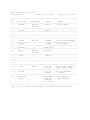
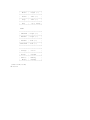
AM/FM/CD Car Stereo
(120-1995)
Features
Faxback Doc. # 6994
You can install the features-packed Optimus Detachable Face Digital AM/FM/
CD Car Stereo in almost any vehicle. When you remove the detachable
control panel, an LED blinks to ward off potential thieves and to show
that your stereo is disabled.
The system offers many easy-to-use features which you can safely operate
while driving.
High Power-gives you 32 watts of power (16 watts per channel for a
2-channel stereo).
Detachable Control Panel-can be removed to discourage potential thieves.
Comes with its own protective case.
Security LED-blinks to show that your stereo is disabled after you remove
the detachable control panel.
30 Memory Tuning Presets-let you quickly tune to any of 18 FM and 12 AM
stations.
Automatic Memory Storage-lets you quickly store stations into memory.
Automatic Memory Scan-lets you scan all stations in memory.
Program Play-lets you program and play a selected CD track.
Repeat Play-lets you hear a desired CD track repeatedly.
Intro Scan-lets you scan a CD by playing only the first 10 seconds of
each track.
Random Play-lets you play randomly selected tracks.
Line-Out Jacks-make it easy to connect an equalizer/booster or power
amplifier.
Lighted Display-makes right operation easy.
Phone Mute-automatically mutes the stereo when you use a car phone.
AM/FM/CD Car Stereo
(120-1995)
Installation
Faxback Doc. # 6993
For easier installation, the supplied 13-wire harness includes all the
lead wires you need to connect the stereo to speakers, power, and
optional components. You might need additional wire to complete
connections, depending on your individual auto sound system. Your local
Radio Shack store carries a full line of wire and wire management
accessories.
Caution: For added safely and to protect your stereo, disconnect the
cable from the negative (-) terminal on your vehicle's battery before
you begin installation.
ROUTING SPEAKER WIRE
If you install speakers, avoid routing the speaker wires near moving
parts or sharp edges. You can usually route them along the wiring
channel beneath the vehicle door's step plates by carefully removing the
molding that holds the carpet in places. After you route the speaker
wires, replace the molding.
CONNECTING SPEAKERS
Any speakers you connect to the stereo must have a combined powerhandling capacity of at least 32 watts, and each individual speaker
must have an impedance of at least 4 ohms. Your local Radio Shack store
carries a full line of automotive speakers.
Caution: You must connect a separate wire to each speaker terminal as
described in the following procedures. Do not use a common wire or
chassis ground for any speaker connection.
Connecting Two Speakers
If you are using only one pair of speakers, set 4CH/2CH on the left side
of the stereo to 2CH. Then connect the speakers to the supplied harness
as follows.
1.
Connect the harness' gray wire to the right speaker's positive (+)
terminal.
2.
Connect the harness' violet wire to the right speaker's negative (-)
terminal.
3.
Connect the harness' white wire to the left speaker's positive (+)
terminal.
4.
Connect the harness' green wire to the left speaker's negative (-)
terminal.
Connecting Four Speakers
If you are using both front and rear speakers, set 4CH/2CH on the left
side of the stereo to 4CH. Then connect the speakers to the supplied
harness as follows.
1.
Connect the harness' gray wire to the front-right speaker's positive
(+) terminal.
2.
Connect the harness' gray/black wire to the front-right speaker's
negative (-) terminal.
3.
Connect the harness' violet wire to the rear-right speaker's positive
(+) terminal.
4.
Connect the harness' violet/black wire to the rear-right speaker's
negative (-) terminal.
5.
Connect the harness' white wire to the front-left speaker's positive
(+) terminal.
6.
Connect the harness' white/black wire to the front-left speaker's
negative (-) terminal.
7.
Connect the harness' green wire to the rear-left speaker's negative
(+) terminal.
8. Connect the harness' green/black wire to the rear-left speaker's negative
(-) terminal.
CONNECTING TO OTHER COMPONENTS
You can connect other audio components (such as an equalizer/booster or
amplifier) to your stereo's speaker or line level outputs. Check the
component's owner's manual for instructions on connecting it to a stereo
and to power.
If you want to turn the optional component on and off with the stereo,
you can connect it to the stereo's dark blue/white wire (labeled AMP
REMOTE TURN ON). This wire does not provide power to the component. It
simply turns it on or off.
to keep it out of the way.
If you do not use this wire, use a wire tie
If your vehicle has an automatic antenna, connect the AMP REMOTE TURN ON
lead to the vehicle's power Antenna lead.
Note: The optional component must be designed for use with an amp remote
turn on lead for the above connection. See the optional component's
owner manual.
CONNECTING TO YOUR CAR PHONE
If you want the stereo's sound to mute when you use your car phone,
connect the pink/white wire to your car phone's mute terminal.
CONNECTING TO POWER AND YOUR VEHICLE'S ANTENNA
1.
Connect the stereo's black ground wire to a metal screw attached to
the vehicle's frame. Be sure the screw is not insulated from the
chassis by a plastic part.
2.
Connect the stereo's yellow wire (with an in-line fuse holder and
MEMORY BACKUP LEAD label) to your battery's positive (+) terminal or
to a non-switched fuse terminal (a terminal that the vehicle's
ignition does not turn on and off). This connection provides 12
volts of continuous power for the radio's memory and the security LED
when the ignition is turned off.
3.
Connect the wire labeled POWER LEAD B (+) (with an in-line fuse
holder) to the accessory (ACC) terminal on your vehicle's fuse block.
This connection provides power to the stereo when you turn on the
ignition, and turns off power when you turn off the ignition. This
prevents your vehicle's battery from draining if you leave the stereo
on and turn off the ignition.
4.
Connect the vehicle's antenna cable to the stereo's large antenna
connector.
When all connections are complete, reconnect the battery cable.
TESTING THE CONNECTIONS
After you connect the speakers, power wires, and antenna, turn on your
vehicle's ignition and test the stereo to be sure it works.
If the stereo does not work, immediately unplug the harness. Recheck
your connections or have a professional automotive audio installer
complete the installation.
If the stereo works, disconnect the cable from the vehicle battery's
negative terminal and continue with installation.
MOUNTING THE STEREO
IF your vehicle does not have a prepared opening for a flat face (DIN E)
component, you must use an in-dash installation kit. Installation kits
for many local Radio Shack store.
If you use an in-dash installation kit, follow its supplied instructions
to mount the mounting sleeve.
If you are using an in-dash installation kit, follow these steps to mount
the stereo.
1.
Disconnect the cable from the vehicle battery's negative (-) terminal.
2.
Temporarily disconnect the wiring harness and antenna.
3.
Insert the mounting sleeve into the dash opening and secure it by
bending the locking tabs out with a screwdriver.
4.
Reconnect the wiring harness and antenna through the sleeve.
5.
Slide the stereo into the sleeve until it locks into place.
Note: To further secure the stereo and ensure proper electrical
grounding, attach the supplied hex bolt to the back of the stereo.
Attach one end of the supplied metal strap to the bolt and the other
end to an existing bolt on a solid metal part of the vehicle.
6.
Reconnect your vehicle battery's negative cable.
REMOVING THE STEREO FROM THE DASH
1.
Disconnect the negative (-) cable from your vehicle's battery.
2.
If you attached the metal strap, release it.
3.
Push the sleeve keys into the slots on the right and left of the
front panel (with the tab facing up) until you hear a click.
4.
Pull the keys out and down to remove the stereo.
Note: To remove the sleeve keys from the slots, press the RELEASE buttons
located directly below the slots on the bottom of the unit.
5.
Disconnect the wiring harness and the antenna cable.
6.
Reconnect the battery's negative (-) cable.
AM/FM/CD Car Stereo
(120-1995)
Operation
Faxback Doc. # 6992
RESETTING THE SYSTEM
If the stereo does not work when you first install it, or if it stops
working, press RESET. This clears any programming except the station
presets and the stereo should begin to work. If it does not work after
you press RESET, take it to your local Radio Shack store for assistance.
SETTING THE CLOCK
1.
Press BAND to turn on the stereo.
shows the clock.
After about 5 seconds, the display
2.
Press and hold down DISPLAY.
3.
While holding down DISPLAY, press << TUNE/SEARCH to set the hours.
4.
While holding down DISPLAY, press TUNE/SEARCH >> to set the minutes.
5.
When the display shows the correct time, release DISPLAY.
CONTROLLING THE SOUND
Use the control buttons to adjust the sound so it suits your listening
preferences.
1.
VOLUME-Press + or - to increase or decrease the volume.
in the display.
Vo appears
Warning: To prevent possible ear injury and hearing loss, do not
listen at high volume.
2.
BALANCE-Press SEL until B and O appear on the display. Press + or to adjust the balance between left and right speakers. BR and a
number appears on the display when the balance is shifted to the
right. BL and a number appear when the balance is shifted to the
left.
3.
BASS-Press SEL until BA and a number appear on the display.
or - to adjust the level of bass signals.
4.
TREBLE-Press SEL until TR and a number appear on the display.
or - adjust the level of treble signals.
Press +
Press +
5.
FADER-Press SEL until F and O appear on the display. Press + or - to
adjust the balance between the front and rear speakers (if you use
both).
FF and a number appear on the display when the fader is shifted to the
front. FR and a number appear when the fader is shifted to the rear.
6.
MUTE- Press MUT until MUTE appears on the display. This reduces the
volume by 20 dB. To return to the original volume, press 'MUT' again.
ENVIRONMENT PRESET MEMORY
You can store treble, bass, balance, fader, and volume settings so they
can be recalled easily.
1.
Repeatedly press SEL to select the control setting you with to store,
(The display shows TR, BA, B, F, and Vo in turn.)
2.
Adjust the setting to the desired level, then press and hold one of
three environment preset buttons (button 1, 2, 3) for more than 2
seconds.
Note:
3.
Button 4, 5, and 6 cannot be used for this memory.
Press 'SEL' and select the environment preset number again within 5
seconds to recall the stored setting.
DETACHING THE CONTROL PANEL
The detachable control panel and LED help to protect your stereo from
theft. When you remove the panel, the red light flashes.
To remove the panel:
1.
Press Release Up arrow.
The left side of the control panel ejects.
2.
Pull the panel's left side toward you.
on the display or drop the panel.
3.
Keep the panel in the supplied protective case for safekeeping.
Take care not to put pressure
To re-attach the panel, push it into the main body, right side first.
Note:
If the control panel is not set correctly, the control buttons will
not work.
Caution: Do not touch the contact on the control panel or on the stereo's
body, since this may result in poor electrical contact. If dirt or other
foreign substances get on the contacts, wipe them off with a dry cloth.
PLAYING THE RADIO
1.
Turn on your vehicle's ignition.
Press BAND to turn on the radio.
2.
Press BAND to select the desired band (F1, F2, or F3 for the FM band;
A1 or A2 for the AM band). Each time you press BAND, the radio
automatically tunes to the last station you selected in that band.
3.
Tune to the desired station manually by pressing << TUNE/SEARCH or
TUNE/SEARCH >> to tune down or up the selected band. Or, press >> bar
or bar << to automatically tune to the next strong station on the band.
4.
Press ST/MO when an FM broadcast is noisy. The unit automatically
switches between mono and stereo as you tune to different stations.
ST appears on the display when you tune to an FM stereo station.
5.
To turn off the radio, press OFF.
MEMORY TUNING
Your radio has two AM memory groups (A1 and A2) and three FM groups (F1,
F2, and F3). You can store up to six stations in each memory group.
You can let the radio search for the next six stations on the band and
automatically enter them into a memory group, or you can enter stations
into a memory group manually.
Tune to a stored station y selecting the memory group and pressing the
correct memory location button.
You can also scan the stations in a memory group.
Storing Stations Automatically
1.
Turn on the radio.
2.
Press BAND to select the desired band and memory group.
For example,
select A1 to store the first group of AM stations.
3.
Tune to the station which appears on the band immediately before the
first station you want to store in memory.
4.
Press and hold down AMS for 3 seconds. The system scans the selected
band and then stores the next six strong stations. The memory location
number and the station's frequency appear on the display for each
stored station.
When it finishes storing stations, the radio begins scanning all stored
stations. The channel number flashes and the radio tunes to each station
for 5 seconds.
Note: The radio scans once for storing stations, twice for weaker
stations and three times for weak stations. After that if all memory
locations are not full, it continues storing previously stored stations
until all locations are full.
Storing Stations Manually
1.
Turn on the radio.
2.
Press BAND to select the band and memory group.
A1 to store the first group of AM stations.
3.
Use any tuning method to tune to the station you want to store into
memory.
4.
Press and hold down the desired memory location number until the audio
momentarily mutes.
For example, select
The memory location number and the station's frequency appear on the
display for each stored station.
Scanning Stored Stations
Press BAND to select the desired band and memory group. Press MS to scan
the stored stations in that group. The radio scans the stored stations,
pausing for 5 seconds at each station. When the radio pauses at a station
you want to listen to, press MS again.
Note: Do not hold down MS.
stations into memory.
This sets the radio to automatically store
PLAYING A CD
Cautions:
*
The CD player has a wide dynamic range. As a result, if you turn your
CD player's volume too high during soft (low volume) sections of a
program, you might damage your speakers when a sudden loud passage
occurs.
*
if the CD player is jolted during play, the rotation speed might
suddenly change or the CD player might make an unusual noise. This
is not a malfunction.
1.
Insert a compact disc (label side up) in the slot.
turns on and starts to play the CD.
The CD player
If a CD is already in the CD player, press >double bar to play the CD.
2.
Adjust VOLUME, BALANCE, BASS, TREBLE, and FADER as desired.
3.
To fast-forward through the selections on the CD, press TUNE/SEARCH
>>. To reverse the CD, press << TUNE/SEARCH.
To change to the next or previous track, press >>bar or bar<<.
To pause playback, press >double bar.
bar<<, >>bar, <<, >>, or >double bar.
To resume play, press
Eject
Press EJ. The disc ejects and the radio turns on automatically (if it
was on before you played a CD). If you do not remove the CD, it reloads
automatically after five seconds.
Intro Scan
The into scan feature lets you scan a CD by playing the first 10 seconds
of each track.
Press INTO to scan the tracks of the current CD. INT and the number of
the next track appear on the display and the track plays for 10 seconds.
The CD player advances to the next track, plays the track for 10 seconds,
then advances to the next track, plays it for 10 seconds, and so on.
To cancel into scan, press INTRO. INT disappears from the display and the
CD player resumes normal play of the current track.
Repeat Play
You can play a selected track repeatedly. Simply press REPEAT while the
track you want to repeat is playing. RPT appears on the display and the
CD player repeats the track. To cancel repeat play, press REPEAT again.
Random Play
Press SHF (shuffle) to play all tracks on the CD in random order.
appears on the display. To cancel random play, press SHF again.
"SHF"
Programming and Playing a Sequence of Tracks
You can program the CD player to play up to 15 tracks in any order you
choose, or to play the same track more than once.
Follow these steps to program a sequence of tracks:
1.
Press PROG. The program number 01, the track number, PROG, and P
appear on the display.
2.
Press bar<< or >>bar to display the number of the track you want to
program.
3.
Press PROG again to store the selected track number in the first
memory location. The track number disappears and the next program
number appears on the display.
4.
Repeat Steps 2 and 3 for each track you want to program, up to 15
tracks.
After programming, press PROG PLAY to play the programming sequence.
PROG and the programmed track number appears on the display.
To clear the program memory, remove the disc, or press CLEAR for more
than 2 seconds.
AM/FM/CD Car Stereo
(120-1995)
Specifications
Faxback Doc. # 6991
CD SECTION (At Line Output
Frequency Response (+/-3 db)..................................20-20,000Hz
S/N Ratio (A-WTD)...................................................80 dB
Separation..........................................................50 dB
AM RADIO
Frequency Coverage............................................530-1710 Hz
IF...............................................................10.7 MHz
Sensitivity.......................................20 Micro V (IHF usable)
Image Rejection.....................................................50 dB
FM RADIO
Frequency Coverage.........................................87.5-107.9 MHz
IF..............................................................107.7 MHz
Sensitivity.......................................2.0.microV (IHF usable)
Image Rejection.....................................................60 dB
Stereo Rejection....................................................30 dB
GENERAL
Power Supply Voltage..........................12 volts DC Negative Ground
Power Output...............................16 Watts RMS per channel (2CH)
55 Watts RMS per channel (4CH)
Load Impedance.......................................4-8 ohms per channel
Current Drain.................................................6 Amps Max.
Dimensions........2 1/4 x 7 3/8 x 7 9/16 inches (50 x 178 x 160 mm) (HWD)
Weight...................................................5.3 lbs (2.5 kg)
Specifications are typical; individual units may vary.
are subject to change without notice.
Specifications
Audio Connection Information
(120-Series)
Plug/Male 2 Ch. System
Faxback Doc.# 19994
+----+--------------+---------------+------------+------------------------+
|Pin |
|
|
|
|
|No. | WIRE COLOR | WIRE SPECS. |
LABEL
|
REMARK
|
+----+--------------+---------------+------------+------------------------+
| 1 |
WHT/BLK
|
AWG #20
| FRONT L- |
STRIP SOLDER
|
|
|
|
2P CORD
|
|
|
+----+--------------+---------------+------------+------------------------+
| 2 |
GRY/BLK
|
"
| FRONT R- |
"
|
+----+--------------+---------------+------------+------------------------+
| 3 |
|
|
|
|
+----+--------------+---------------+------------+------------------------+
| 4 |
|
|
|
|
+----+--------------+---------------+------------+------------------------+
| 5 |
BLACK
|
AWG 206
|
GROUND
| 6.3mm r FORK TERMINAL |
+----+--------------+---------------+------------+------------------------+
| 6 |
ORG/WHT * |
"
|
DIMMER
|
STRIP SOLDER
|
+----+--------------+---------------+------------+------------------------+
| 7 | PINK/WHT * |
"
| PHONE MUTE |
"
|
+----+--------------+---------------+------------+------------------------+
| 8 |
WHITE
|
AWG #20
| FRONT L+ |
|
|
|
|
2p CORD
|
|
"
|
+----+--------------+---------------+------------+------------------------+
| 9 |
GRAY
|
"
| FRONT R+ |
"
|
+----+--------------+---------------+------------+------------------------+
| 10 |
|
|
|
|
+----+--------------+---------------+------------+------------------------+
| 11 |
|
|
|
|
+----+--------------+---------------+------------+------------------------+
| 12 |
RED
|
AWG #20
| +12 V TO
| 250/ 1A FUSE & 24M/M
|
|
|
|
| IGNITION
| TRANS STRIP SOLDER
|
+----+--------------+---------------+------------+------------------------+
| 13 |
YELLOW
|
"
| +12 V TO
| 250/ 1A FUSE STRIP
|
|
|
|
| BATTERY
|
SOLDER
|
+----+--------------+---------------+------------+------------------------+
| 14 | DARK BLUE/ |
"
| AMP REMOTE |
WIRE BANDING &
|
|
|
WHITE
|
| TURN ON
|
TUBE HEATING
|
|
|
|
| 500mA MAX |
|
|
|
|
|+12 V OUTPUT|
|
|
|
|
|
|
|
+----+--------------+---------------+------------+------------------------+
* May or may not be present depending on features of individual radios.
(2CH/4CH SWITCHABLE UNIT)
+----+--------------+---------------+------------+------------------------+
|Pin |
|
|
|
|
|No. | WIRE COLOR | WIRE SPECS. |
LABEL
|
REMARK
|
+----+--------------+---------------+------------+------------------------+
| 1 |
WHT/BLK
|
AWG #20
| FRONT L- |
STRIP SOLDER
|
|
|
|
2P CORD
|
|
|
+----+--------------+---------------+------------+------------------------+
| 2 |
GRY/BLK
|
"
| FRONT R- |
"
|
+----+--------------+---------------+------------+------------------------+
| 3 |
GRN/BLK
|
"
| REAR L|
"
|
+----+--------------+---------------+------------+------------------------+
| 4 |
VIO/BLK
|
"
| REAR R|
"
|
+----+--------------+---------------+------------+------------------------+
| 5 |
BLACK
|
AWG 206
|
GROUND
| 6.3mm r FORK TERMINAL |
+----+--------------+---------------+------------+------------------------+
| 6 |
ORG/WHT * |
"
|
DIMMER
|
STRIP SOLDER
|
+----+--------------+---------------+------------+------------------------+
| 7 | PINK/WHT * |
"
| PHONE MUTE |
"
|
+----+--------------+---------------+------------+------------------------+
| 8 |
WHITE
|
AWG #20
| FRONT L+ |
|
|
|
|
2p CORD
|
|
"
|
+----+--------------+---------------+------------+------------------------+
| 9 |
GRAY
|
"
| FRONT R+ |
"
|
+----+--------------+---------------+------------+------------------------+
| 10 |
GREEN
|
"
| REAR L+
|
|
+----+--------------+---------------+------------+------------------------+
| 11 |
VIOLET
|
"
| REAR R+
|
"
|
+----+--------------+---------------+------------+------------------------+
| 12 |
RED
|
AWG #20
| +12 V TO
| 250/ 1A FUSE & 24M/M
|
|
|
|
| IGNITION
| TRANS STRIP SOLDER
|
+----+--------------+---------------+------------+------------------------+
| 13 |
YELLOW
|
"
| +12 V TO
| 250/ 1A FUSE STRIP
|
|
|
|
| BATTERY
|
SOLDER
|
+----+--------------+---------------+------------+------------------------+
| 14 | DARK BLUE/ |
"
| AMP REMOTE |
WIRE BANDING &
|
|
|
WHITE
|
| TURN ON
|
TUBE HEATING
|
|
|
|
| 500mA MAX |
|
|
|
|
|+12 V OUTPUT|
|
+----+--------------+---------------+------------+------------------------+
* May or may not be present depending on features of individual radios.
4 Chnl Unit
+----+--------------+---------------+------------+------------------------+
|Pin |
|
|
|
|
|No. | WIRE COLOR | WIRE SPECS. |
LABEL
|
REMARK
|
+----+--------------+---------------+------------+------------------------+
| 1 |
WHT/BLK
|
AWG #20
| FRONT L- |
STRIP SOLDER
|
|
|
|
2P CORD
|
|
|
+----+--------------+---------------+------------+------------------------+
| 2 |
GRY/BLK
|
"
| FRONT R- |
"
|
+----+--------------+---------------+------------+------------------------+
| 3 |
GRN/BLK
|
"
| REAR L|
"
|
+----+--------------+---------------+------------+------------------------+
| 4 |
VIO/BLK
|
"
| REAR R|
"
|
+----+--------------+---------------+------------+------------------------+
| 5 |
BLACK
|
AWG 206
|
GROUND
| 6.3mm r FORK TERMINAL |
+----+--------------+---------------+------------+------------------------+
| 6 |
ORG/WHT * |
"
|
DIMMER
|
STRIP SOLDER
|
+----+--------------+---------------+------------+------------------------+
| 7 | PINK/WHT * |
"
| PHONE MUTE |
"
|
+----+--------------+---------------+------------+------------------------+
| 8 |
WHITE
|
AWG #20
| FRONT L+ |
|
|
|
|
2p CORD
|
|
"
|
+----+--------------+---------------+------------+------------------------+
| 9 |
GRAY
|
"
| FRONT R+ |
"
|
+----+--------------+---------------+------------+------------------------+
| 10 |
GREEN
|
"
| REAR L+
|
|
+----+--------------+---------------+------------+------------------------+
| 11 |
VIOLET
|
"
| REAR R+
|
"
|
+----+--------------+---------------+------------+------------------------+
| 12 |
RED
|
AWG #20
| +12 V TO
| 250/ 1A FUSE & 24M/M
|
|
|
|
| IGNITION
| TRANS STRIP SOLDER
|
+----+--------------+---------------+------------+------------------------+
| 13 |
YELLOW
|
"
| +12 V TO
| 250/ 1A FUSE STRIP
|
|
|
|
| BATTERY
|
SOLDER
|
+----+--------------+---------------+------------+------------------------+
| 14 | DARK BLUE/ |
"
| AMP REMOTE |
WIRE BANDING &
|
|
|
WHITE
|
| TURN ON
|
TUBE HEATING
|
|
|
|
| 500mA MAX |
|
|
|
|
|+12 V OUTPUT|
|
+----+--------------+---------------+------------+------------------------+
* May or may not be present depending on features of individual radios.
5-Pin DIN
FRONT
+---------+--------------+
| Green | Right (+)
|
+---------+--------------+
| White | Right (-)
|
+---------+--------------+
| Brown | Left (+)
|
+---------+--------------+
| Gray
| Left (-)
|
+---------+--------------+
| Red
| +12 V Power |
+---------+--------------+
REAR
+---------+--------------+
| GRN/BLK | Right (+)
|
+---------+--------------+
| WH/BLK | Right (-)
|
+---------+--------------+
| BR/BLK | Left (+)
|
+---------+--------------+
|GRAY/BLK | Left (-)
|
+---------+--------------+
+---------+--------------+
| Orange | S.P.L.
|
+---------+--------------+
| Black
| Ground
|
+---------+--------------+
| Red w/ | Memory
|
| White | Backup
|
+---------+--------------+
(smm/ir-06/12/95)
LN-03/04