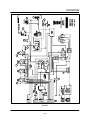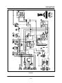
1
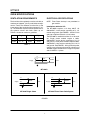
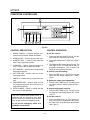
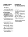
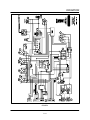
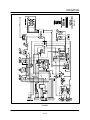
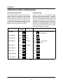
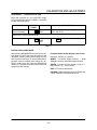
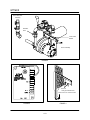
MT1828
CONVEYOR OVEN
SERVICE AND REPAIR MANUAL
BLODGETT OVEN COMPANY
www.blodgettcorp.com
50 Lakeside Avenue, Box 586, Burlington, Vermont 05402 USA Telephone (800) 331-5842, (802) 860-3700 Fax: (802)864-0183
PN M8560 Rev C (6/01)
E 2001 --- G.S. Blodgett Corporation All rights reserved.
Duplication of the information in this manual is prohibited without the consent of the Blodgett Service Department.
TABLE OF CONTENTS
1. INTRODUCTION
Oven Specifications . . . . . . . . . . . . . . . . . . . . . . . . . . . . . . . . . . . . . . . . . . . . . . . . . . . . . . . . . . . . . . .
Ventilation Requirements . . . . . . . . . . . . . . . . . . . . . . . . . . . . . . . . . . . . . . . . . . . . . . . . . . . . . . .
Electrical Specifications . . . . . . . . . . . . . . . . . . . . . . . . . . . . . . . . . . . . . . . . . . . . . . . . . . . . . . . .
Gas Specifications . . . . . . . . . . . . . . . . . . . . . . . . . . . . . . . . . . . . . . . . . . . . . . . . . . . . . . . . . . . .
1
1
1
3
2. OPERATION
Computer Controller . . . . . . . . . . . . . . . . . . . . . . . . . . . . . . . . . . . . . . . . . . . . . . . . . . . . . . . . . . . . . .
Control Description . . . . . . . . . . . . . . . . . . . . . . . . . . . . . . . . . . . . . . . . . . . . . . . . . . . . . . . . . . . .
Control Operation . . . . . . . . . . . . . . . . . . . . . . . . . . . . . . . . . . . . . . . . . . . . . . . . . . . . . . . . . . . . .
Programming Procedures . . . . . . . . . . . . . . . . . . . . . . . . . . . . . . . . . . . . . . . . . . . . . . . . . . . . . .
Display Information . . . . . . . . . . . . . . . . . . . . . . . . . . . . . . . . . . . . . . . . . . . . . . . . . . . . . . . . . . . .
Sequence of Operation . . . . . . . . . . . . . . . . . . . . . . . . . . . . . . . . . . . . . . . . . . . . . . . . . . . . . . . . . . . .
MT1828G Domestic and General Export Ovens Internal Mount --- M7296 Rev B . . . . . . .
MT1828G Domestic and General Export Ovens External Mount --- M9776 Rev B . . . . . .
MT1828E Domestic and General Export Ovens --- M6314 Rev C . . . . . . . . . . . . . . . . . . . .
MT1828G CE Ovens --- M6462 Rev B . . . . . . . . . . . . . . . . . . . . . . . . . . . . . . . . . . . . . . . . . . . .
MT1828E CE Ovens --- M6453 Rev A . . . . . . . . . . . . . . . . . . . . . . . . . . . . . . . . . . . . . . . . . . . .
2---1
2---1
2---1
2---2
2---2
2---3
2---3
2---5
2---7
2---9
2---11
3. CALIBRATION AND ADJUSTMENT
Convection Blower Motors . . . . . . . . . . . . . . . . . . . . . . . . . . . . . . . . . . . . . . . . . . . . . . . . . . . . . . . . .
To check motor rotation . . . . . . . . . . . . . . . . . . . . . . . . . . . . . . . . . . . . . . . . . . . . . . . . . . . . . . . .
To check low-limit . . . . . . . . . . . . . . . . . . . . . . . . . . . . . . . . . . . . . . . . . . . . . . . . . . . . . . . . . . . . .
Regulated Gas Pressure . . . . . . . . . . . . . . . . . . . . . . . . . . . . . . . . . . . . . . . . . . . . . . . . . . . . . . . . . . .
Computer Control Configuration . . . . . . . . . . . . . . . . . . . . . . . . . . . . . . . . . . . . . . . . . . . . . . . . . . . .
Temperature Calibration . . . . . . . . . . . . . . . . . . . . . . . . . . . . . . . . . . . . . . . . . . . . . . . . . . . . . . . . . . .
Belt Speed Calibration . . . . . . . . . . . . . . . . . . . . . . . . . . . . . . . . . . . . . . . . . . . . . . . . . . . . . . . . . . . .
Closed Loop System . . . . . . . . . . . . . . . . . . . . . . . . . . . . . . . . . . . . . . . . . . . . . . . . . . . . . . . . . .
Open Loop System . . . . . . . . . . . . . . . . . . . . . . . . . . . . . . . . . . . . . . . . . . . . . . . . . . . . . . . . . . . .
Motor Control Board . . . . . . . . . . . . . . . . . . . . . . . . . . . . . . . . . . . . . . . . . . . . . . . . . . . . . . . . . . .
3---1
3---1
3---1
3---2
3---3
3---5
3---6
3---6
3---7
3---8
4. ENHANCEMENTS
Burner . . . . . . . . . . . . . . . . . . . . . . . . . . . . . . . . . . . . . . . . . . . . . . . . . . . . . . . . . . . . . . . . . . . . . . . . . .
Igniter and Flame Rods . . . . . . . . . . . . . . . . . . . . . . . . . . . . . . . . . . . . . . . . . . . . . . . . . . . . . . . . . . . .
4---1
4---4
5. TROUBLESHOOTING
DC Drive System . . . . . . . . . . . . . . . . . . . . . . . . . . . . . . . . . . . . . . . . . . . . . . . . . . . . . . . . . . . . . . . . .
Computer Control System . . . . . . . . . . . . . . . . . . . . . . . . . . . . . . . . . . . . . . . . . . . . . . . . . . . . . . . . .
Heating System . . . . . . . . . . . . . . . . . . . . . . . . . . . . . . . . . . . . . . . . . . . . . . . . . . . . . . . . . . . . . . . . . .
Convection System . . . . . . . . . . . . . . . . . . . . . . . . . . . . . . . . . . . . . . . . . . . . . . . . . . . . . . . . . . . . . . .
5---1
5---2
5---3
5---5
i
CHAPTER 1
INTRODUCTION
MT1828
OVEN SPECIFICATIONS
VENTILATION REQUIREMENTS
ELECTRICAL SPECIFICATIONS
The hood should completely cover the unit with an
overhang of at least 6” (15 cm) on all sides not adjacent to a wall. The distance from the floor to the
lower edge of the hood should not exceed 7’ (2.1
m). The ventilation system should replace 80% of
the exhaust volume with fresh make up air.
TABLE 1 should be used as a guideline.
NOTE: Three Phase hookup is not permitted on
gas models.
Single
Double
Triple
CFM
400-500
900-1000
1200-1500
M3/min
14 - 17
28-34
42-51
Installations within the U.S.
The MT1828G requires a 15 Amp, 60HZ, 1Φ,
208-240VAC, 4 wire service consisting of L1, L2,
neutral and ground. See FIGURE 1. Use 90_C wire
and size to National Electric or local codes.
The MT1828E is available in either 1Φ or 3Φ models. Single phase models require a 60Hz,
208/240VAC, 3 wire service consisting of L1, L2
and ground. Three phase models require a 60Hz,
208/240VAC, 4 wire service consisting of L1, L2, L3
and ground. See FIGURE 1. Wiring from the power
source to any of these units must be a minimum of
#8 AWG copper stranded wire or larger for 3 phase
and #4 AWG for 1 phase.
TABLE 1
L1
Supply
N
120
L2
120
208-240
Oven
MT1828G
L1
Supply
L2
L1
208/240
L2
Oven
Supply
MT1828E Single Phase
L3
208/240
Oven
MT1828E Three Phase Delta System
FIGURE 1
1
MT1828
Installations outside the U.S.
L1, L2, L3, neutral and ground. See FIGURE 2. Use
a minimum of 8.37 mm2 copper stranded wire or
larger for 3 phase and 21.15 mm2 for 1 phase.
The MT1828G requires a 15 Amp, 50Hz, 1Φ, 240
VAC, 3 wire service consisting of L1, neutral and
ground. See FIGURE 2. Use 90_C wire and size
wire according to local codes.
CE approved installations
The MT1828G requires 15 Amp, 50Hz, 1Φ, 230
VAC, 3 wire service consisting of L1, neutral and
ground. Connect exhaust fan connector 1 and 2.
See FIGURE 2. Use 90_C wire and size according
to local codes.
The MT1828E is available in either 1Φ or 3Φ models. Single phase models require a 50 Hz,
220/240VAC, 3 wire service consisting of L1, L2
and ground. Three phase models are available in
either Delta or WYE configurations. Delta models
require 50Hz, 208/240VAC, 4 wire service consisting of L1, L2, L3 and ground. WYE models require
50 Hz, 220/240 VAC, 5 wire service consisting of
The MT1828G requires 50 Hz, 3Φ, 230VAC, 5 wire
service consisting of L1, L2, L3, neutral and
ground. See FIGURE 2. Use 90_C wire and size
according to local codes.
L1
L1
240
N
Supply
Oven
Supply
MT1828G Export Installations
220/230/240
Oven
MT1828E Single Phase Export Installations
L1
L1
L2
Supply
L2
208/240
L3
Supply
Oven
L2
415/400*/380
L3
415/400*/380
415/
400*/
380
240/
230*/
220
N
Oven
* --- CE Approved Installations
MT1828E Three Phase Delta System
Export Installations
MT1828E Three Phase WYE System
Export and CE Installations
2-4-92
L3
L2
L1
N
Blodgett N
Connector
L
Connector
1
2
A2
L1
Supply
N
A1
2 s
230
Fan
Oven
MT1828G CE Approved Installations
FIGURE 2
2
Relay A
1
2 Air Pressure Regulator
1 Burner Control Solenoid
MT1828
GAS SPECIFICATIONS
GAS CONNECTIONS
GAS REQUIREMENTS
Domestic and General Export installations
The firing rate for the MT1828G is 33,000 BTU/Hr.
(9.7 kW/Hr.)
The gas line should be large enough to accommodate the peak demand of all the gas appliances.
TABLE 2 reflects a straight line, 50 foot run with no
coupling restrictions and no other appliances
drawing service. Gas line installations MUST conform to National Fuel Gas Code NFPA 54/ANSI
Z223.1 Sec. 1.4 (Latest Edition). TABLE 2 should
be used as a guideline only.
NOTE: For natural gas meter sizing, consult your
local gas company to ensure that your meter will provide the proper supply.
Installations within the U.S.
1. Add the total BTU’s/hr of all the gas
appliances.
NOTE: For any pipe runs over 50 feet (15 m), consult the factory.
2. Convert BTU’s to cubic ft/hr using the formula
Cu Ft/Hr = 1000 BTU/Hr for natural gas.
CE approved installations
3. Size the meter accordingly.
1. Connect the oven to the gas line with the proper type of gas according to Local and National
Installation Standards. See TABLE 2.
Installations outside the U.S.
1. Add the total M3/min of all the appliances.
2. Size the meter accordingly.
DOMESTIC AND GENERAL EXPORT
Natural Gas
Propane Gas
Single
3/4” line
3/4” line
Double
3/4” line
3/4” line
Triple
3/4” line
3/4” line
Orifice Size
#34 MTD
#49 MTD
Gas Line Sizing
Incoming Gas Pressure
W.C.
kPa
mbar
W.C.
kPa
mbar
7”
1.74
17.4
12.5”
3.11
31.1
5.5”
1.36
13.7
11”
2.73
27.4
3.5”
0.87
9
10”
2.49
25
Static
Operational
Manifold Gas Pressure
CE APPROVED UNITS
Type of
Gas
Inlet
Pressure
mbars
Burner Pressure
mbars
Injector
Air
Diameter Opening
mm
mm
G25
25
8
3,1
22,3
9,8 Nat. Gas
G20
20
8
2,7
22,3
9,8 Nat. Gas
G20/G25
20/25
Totally Inscrewed
Pressure Regulator
2,3
22,3
9,8 Nat. Gas
G30
30/50
24
1,55
22,3
9,8 Butane
G31
30/37/50
24
1,7
22,3
9,8 Propane
TABLE 2
3
Standard Delivery
Value kW (HS)
CHAPTER 2
OPERATION
MT1828
COMPUTER CONTROLLER
1
2
9
3
8
7
6
5
4
FIGURE 1
CONTROL DESCRIPTION
CONTROL OPERATION
1. DIGITAL DISPLAY --- Displays the time, temperature and controller related information.
To turn the oven on:
1. Press and hold the ON/OFF key (2). The display reads OFF when the oven is idle.
2. The display flashes WAIT D LOW D SET D TIME D
mmss.
3. The FAN and HEAT status lamps (9) light. The
fans begin to run. The heat rises to the programmed temperature. The conveyor belt
travels at the programmed speed.
2. OVEN ON/OFF --- Controls power to the oven.
3. NUMERIC KEYS --- Used to enter numerical
data in the programming mode.
4. CLEAR KEY --- Used to clear the display if an
error is made in the programming mode.
5. SET TEMP KEY --- Used to view or program the
temperature setpoint.
To view the cook time setting:
6. ACT TEMP KEY --- Used to view the current
oven temperature.
1. Press the TIME key (7). The LED on the key
lights and the display flashes SET D TIME D
mmss.
7. TIME KEY --- Used to view or program the cook
time.
To display the actual oven temperature:
8. PROG/ENTER KEY --- Used to enter and exit
the programming mode. Also used to lock in
programmed settings.
1. Press the ACT TEMP key (6). The LED on the
key lights and the display reads ACTUAL D
nnnn_F.
9. STATUS LAMPS --- When lit indicate that the
fan or burners are operating.
To view the temperature set point:
1. Press the SET TEMP key (5). The LED on the
key lights and the display flashes SET D TEMP
D nnnn_F.
This oven, supplied with remote control, is
equipped with an emergency shut down
switch. Should you need to stop the belt,
fans, or heat press the emergency switch.
To turn the oven off:
1. Press the ON/OFF key (2). The blower motor(s) continue to run regardless of the controller status until the temperature drops below
180_F (82_C).
Do not use the emergency switch as a
GENERAL on/off switch!
2---1
OPERATION
PROGRAMMING PROCEDURES
DISPLAY INFORMATION
Programming the Cook Time:
D
1. Press the PROGRAM/ENTER key (8).
2. Press the TIME key (7). The display reads
PROG-? D SET D TIME-? D _ _ _ _.
D
3. Use the NUMERIC keys (3) to enter the desired
cook time. The display will read the numbers
as they are entered. If an error is made, press
the CLEAR key (4) and re-enter the number.
D
D
4. Press the PROGRAM/ENTER key (8) a second
time to lock-in the new time. The new cook time
will be stored in the computer’s memory.
Programming the Temperature:
1. Press the PROGRAM/ENTER key (8).
D
2. Press the SET TEMP key (5). The display reads
PROG-? D SET D TEMP-? D _ _ _ __F.
3. Use the NUMERIC keys (3) to enter the desired
temperature set point. The control displays the
numbers as they are entered. If an error is
made, press the CLEAR key (4) and re-enter
the number.
D
D
4. Press the PROGRAM/ENTER key (8) a second
time to lock-in the new temperature. The new
temperature setpoint will be stored in the computer’s memory.
D
D
Operation at the Programmed Settings:
1. Press and hold the ON/OFF key (2).
2. The FAN and HEAT status lamps (9) light. The
fans begin to run. The heat rises to the temperature setting stored in the computer’s memory.
The conveyor belt begins to travel at the timed
speed stored in memory.
3. The display will flash WAIT D LOW D SET D TIME
D mmss until the programmed bake temperature is reached. The HEAT lamp (9) will remain
lit until the oven reaches the temperature set
point.
4. The display reads READY and the HEAT lamp
(9) goes out.
5. The oven is now ready to accept product.
6. Press and hold the ON/OFF key (2) to turn the
oven off. The fans continue to run while the
oven cools to a safe temperature.
2---2
WAIT D LOW --- indicates that the present oven
temperature is lower than the set point temperature. When the oven reaches the set point
temperature the display changes to READY.
READY --- indicates that the oven is ready to accept product.
SET D TIME D mmss --- indicates the current
cook time setting.
HIGH D TIME --- indicates that the temperature
is well above the set point. This usually occurs
when moving from a higher to a lower temperature. Wait until the display reads ready before
loading product.
HIGH D TEMP D LIMIT --- indicates that the oven
temperature exceeds the high limit from the
2nd level program. The Over Temperature
Alarm buzzer will sound. Shut the oven off and
wait for the unit to cool down.
MTR D SPD --- indicates speed of the motor
does not match the set point.
MOTOR --- indicates the computer is not receiving the signal back from the pickup.
HI D TEMP D MOTOR --- N.A.
PROBE D OPEN D PROBE D SHORT --- indicates
that the temperature sensor has failed. The
Alarm buzzer sounds. Shut the oven off and
contact a service representative.
MT1828
SEQUENCE OF OPERATION
MT1828G DOMESTIC AND GENERAL EXPORT OVENS INTERNAL MOUNT --- M7296
REV B
COMPONENT REFERENCE
terminal of a single pole double throw thermal
switch (5).
NOTE: Refer to FIGURE 2 for component locations.
1.
2.
3.
4.
5.
6.
7.
8.
9.
10.
11.
12.
13.
14.
15.
16.
17.
18.
19.
3. When the belt stop relay (2) closes, 110 V.A.C.
are sent to the motor control board (6) and the
single pole single throw thermal switch (7). If
this switch is closed, power goes to the resetable hi limit switch (8).
BLOWER RELAY
BELT STOP RELAY
HEAT RELAY
MOTOR CONTACTOR
SINGLE POLE DOUBLE THROW THERMAL
SWITCH
MOTOR CONTROL BOARD
SINGLE POLE SINGLE THROW THERMAL
SWITCH
RESETABLE HI LIMIT
115/24 VOLT TRANSFORMER
FLAME BLOWER
IGNITION CONTROL MODULE
COOKING COMPUTER
PRESSURE SWITCH
H.S.I.
BURNER VALVE
PROOF OF FLAME ROD
SINGLE POLE DOUBLE THROW THERMAL
SWITCH
CONVECTION BLOWERS
COOLING FANS
4. If the resetable hi limit switch is closed power
goes to the 115/24 volt transformer (9) located
in the box mounted on the flame blower (10).
The flame blower starts.
5. The secondary side of the transformer (9)
sends 24 volts to L1 of the ignition control module (11) and one side of the heat relay (3). If the
computer (12) closes the heat relay, the 24
volts will go to the pressure switch (13).
6. If the pressure switch is closed, a circuit will be
completed back to the ignition module (11).
7. The ignition module initiates its firing sequence
by sending power to the H.S.I. (14). After a
warm up period both solenoids on the burner
valve (15) open allowing gas to enter for ignition. If no flame is sensed by the proof of flame
rod (16) the system shuts down.
NOTE: Some ignition control modules may try
to refire up to 3 times. However, there
will be a longer warm up period between each attempt at ignition.
OPERATION
8. The thermal switches (5 and 17) toggle from
common to N.O. only when they reach the temperature stated on the back of the switch.
1. Apply power to the oven. Program time and
temperature into the computer (12). The blower relay (1), belt stop relay (2) and heat relay (3)
close.
9. The convection blowers (18) receive their power from the motor contactor (4) only.
10. The cooling fans (19) come on only when the
motor contactor (4) is energized or if the thermal switches (5 and 17) have toggled.
2. When the blower relay (1) closes, 110 V.A.C.
are sent to the coil of the motor contactor (4)
starting the convection blowers (18) and N.C.
2---3
FIGURE 2
2---4
19
19
12
19
19
19
17
1
5
6
2
11
3
4
13
7
18
18
8
15
14
16
9
10
OPERATION
MT1828
MT1828G DOMESTIC AND GENERAL EXPORT OVENS EXTERNAL MOUNT --- M9776
REV B
COMPONENT REFERENCE
motor contactor closes, power is also applied
to the NIC terminal of a single pole double
throw thermal switch (5).
NOTE: Refer to FIGURE 2 for component locations.
1.
2.
3.
4.
5.
6.
7.
8.
9.
10.
11.
12.
13.
14.
15.
16.
17.
18.
19.
3. When the belt stop relay (2) closes, 110 V.A.C.
are sent to the motor control board (6) and a
single pole single throw thermal switch (7). If
this switch is closed, power goes to the resetable hi limit switch (8).
BLOWER RELAY
BELT STOP RELAY
HEAT RELAY
MOTOR CONTACTOR
SINGLE POLE DOUBLE THROW THERMAL
SWITCH
MOTOR CONTROL BOARD
SINGLE POLE SINGLE THROW THERMAL
SWITCH
RESETABLE HI LIMIT
115/24 VOLT TRANSFORMER
FLAME BLOWER
IGNITION CONTROL MODULE
COOKING COMPUTER
PRESSURE SWITCH
H.S.I.
BURNER VALVE
PROOF OF FLAME ROD
SINGLE POLE DOUBLE THROW THERMAL
SWITCH
CONVECTION BLOWERS
COOLING FANS
4. If the resetable hi limit switch is closed power
goes to the 115/24 volt transformer (9) located
in the box mounted on the flame blower (10).
The flame blower starts.
5. The secondary side of the transformer (9)
sends 24 volts to one side of the heat relay (3).
If the computer (12) closes the heat relay, the
24 volts will go to the pressure switch (13).
6. If the pressure switch is closed, a circuit will be
completed to the ignition module (11).
7. The ignition module initiates its firing sequence
by starting to spark at the spark electrode (14)
and opening both solenoid valves on the burner valve (15) allowing gas to enter for ignition.
If no flame is sensed by the proof of flame rod
(16) the system shuts down.
NOTE: Some ignition control modules may try
to refire up to 3 times. However, there
will be a longer interpurge period between each attempt at ignition.
OPERATION
8. The thermal switch (17) toggles from common
to N.O. only when it reaches the temperature
stated on the back of the switch.
1. Apply power to the oven. Program time and
temperature into the computer (12). The blower relay (1), belt stop relay (2) and heat relay (3)
close.
9. The convection blowers (18) receive their power from the motor contactor (4) only.
10. The cooling fans (19) come on only when the
motor contactor (4) is energized or if the thermal switch (17) has toggled.
2. When the blower relay (1) closes, 110 V.A.C.
are sent to the coil of the motor contactor (4)
starting the convection blowers (18). When the
2---5
12
19
1
17
2
6
3
4
11
13
7
18
8
14
16
10
9
OPERATION
FIGURE 3
2---6
MT1828
MT1828E DOMESTIC AND GENERAL EXPORT OVENS --- M6314 REV C
COMPONENT REFERENCE
OPERATION
NOTE: Refer to FIGURE 4 for component locations.
1. Apply power to the oven. Program the time and
temperature into the computer (1). The blower
relay (2), belt stop relay (3) and heat relay (4)
are energized.
1.
2.
3.
4.
5.
6.
7.
8.
9.
10.
11.
12.
13.
14.
15.
COMPUTER
BLOWER RELAY
BELT STOP RELAY
HEAT RELAY
208/120 STEP DOWN TRANSFORMER
MOTOR CONTACTOR
SINGLE POLE DOUBLE THROW THERMAL
SWITCH
CONVECTION FANS
COOLING FANS
SPEED CONTROL BOARD
D.C. MOTOR
SINGLE POLE SINGLE THROW THERMAL
SWITCH
RESETABLE HI LIMIT
CONTACTOR
ELEMENTS
2. If the contacts in the blower relay close the 110
V.A.C. supplied from the 240/120 step down
transformer (5) will go to the coil of the motor
contactor (6) and the N.C. terminals of two
single pole double throw thermal switches (7).
These switches toggle when ambient air passing the face of the switch exceeds the rating on
the back of the switch.
3. If the motor contactor (6) and the thermal
switches (7) are closed the convection fans (8)
and cooling fans (9) will start.
4. The belt stop relay (3) should be closed sending 110 V.A.C. to the speed control board (10).
5. If the speed control board is working it sends
out a variable amount of D.C. voltage to the
D.C. motor (11). The voltage can vary from 20
to 130 VDC depending on the amount of time
programmed into the computer (1).
6. The heat relay (4) closes with a call for heat
sending power to a single pole single throw
thermal switch (12). This switch acts as a temperature limiting device for the controls and
opens if the ambient air around the control exceeds the rating on the back of the switch.
7. If the switch is closed, 110 VAC goes to the resetable hi limit (13). This switch acts as an oven
hi limit and opens if the temperature in the oven
exceeds 630_F (333_C).
8. If the resetable high limit switch is closed the
power will go to one side of the contactor coil
(14). This contactor powers the elements (15).
9. When the motor contactor (6) closes the convection fans (8) start. If the thermal switches
are closed between the N.C. and C. terminals
the cooling fans (9) will start.
2---7
FIGURE 4
2---8
9
9
1
9
9
9
7
2
7
11
10
3
5
6
4
12
8
14
13
8
15
OPERATION
MT1828
MT1828G CE OVENS --- M6462 REV B
COMPONENT REFERENCE
4. If the hi limit (9) is closed, power goes to the
convection blower pressure switch (10). This
switch closes when the convection blowers
(11) are operating. If the switch is closed, power goes to the flame blower (12), the common
terminal of the burner pressure switch (13) and
terminal #7 of the latching relay (14).
5. If the burner pressure switch (13) is closed between COM and N.C., power goes to #4 and
the coil of the latching relay (14). This closes
the relay from #4 to #7 and #6 to #9. The relay
remains latched due to the power on #7 running through #4 to the coil.
6. When the flame blower (12) reaches speed, a
differential in pressure is created in the burner
pressure switch (13). The switch toggles from
COM and N.C. to COM and N.O. This supplies
power to #9 of the latching relay (14) which
should be closed through to #6, sending power to a purge timer (15).
7. When the purge timer (15) times out it sends
power to the coil of a single pole single throw
relay (16).
8. If the burner valve relay (4) is closed, power
goes to a single pole single throw thermal
switch (17). This switch acts as a control hi limit. It opens if the ambient air temperature
reaches the range on the back of the switch.
9. If the switch is closed, power goes through the
closed set of contacts in the relay (16) to terminal #17 of the ignition module (18).
10. After a warmup period for the H.S.I. (19), the
ignition control module (18) powers up the
dual solenoid gas valve (20). If the proof of
flame rod (21) does not sense a flame in 1 second, the ignition control module shuts the system down.
11. The single pole double throw switch (22) gets
its power from the motor contactor (5). This
switch is closed between the common and
N.C. terminals, powering the cooling fans (23).
The switch toggles if the ambient air passing
the facing of the switch exceeds the number on
the back of the switch.
12. The D.C. drive motor (24) gets voltage from the
speed control board (8). The speed of the drive
motor varies with the time programmed into
the computer. The voltage range for this board
is from 20 to 180 V.D.C. measured at A1 and A2
of the speed control board (8).
NOTE: Refer to FIGURE 5 for component locations.
1.
2.
3.
4.
5.
6.
7.
8.
9.
10.
11.
12.
13.
14.
15.
16.
17.
18.
19.
20.
21.
22.
23.
24.
COMPUTER
MAIN CONTROL RELAY
BLOWER RELAY
BURNER VALVE RELAY
MOTOR CONTACTOR
SINGLE POLE DOUBLE THROW THERMAL
SWITCH
CONTROL COMPARTMENT COOLING FAN
SPEED CONTROL BOARD
RESETABLE HI LIMIT
CONVECTION BLOWER PRESSURE SWITCH
CONVECTION BLOWERS
FLAME BLOWER
BURNER PRESSURE SWITCH
LATCHING RELAY
PURGE TIMER
SINGLE POLE SINGLE THROW RELAY
SINGLE POLE SINGLE THERMAL SWITCH
IGNITION CONTROL MODULE
H.S.I.
DUAL SOLENOID GAS VALVE
PROOF OF FLAME ROD
SINGLE POLE DOUBLE THROW SWITCH
COOLING FANS
D.C. DRIVE MOTOR
OPERATION
1. Apply power to the oven. Program time and
temperature into the computer (1). The main
control relay (2) blower relay (3) and burner
valve relay (4) will energize.
2. The blower relay (3) sends power to the coil of
the motor contactor (5) and the N.C. terminal
of a single pole double throw thermal switch
(6). This switch starts the control compartment
cooling fan (7). The motor contactor energizes
the convection blowers (11) and the N.C. terminal of another thermal switch (22).
3. The main control relay (2) sends 230 VAC to
the speed control board (8) and the resetable
hi limit (9).
2---9
FIGURE 5
2---10
23
23
1
23
23
7
22
6
2
24
8
3
4
5
18
9
11
20
10
17
11
13
16
12
19
21
15
14
OPERATION
MT1828
MT1828E CE OVENS --- M6453 REV A
COMPONENT REFERENCE
OPERATION
NOTE: Refer to FIGURE 6 for component locations.
1. Apply power to the oven. Program the time and
temperature into the computer (1). The blower
relay (2), belt stop relay (3) and heat relay (4)
are energized.
1.
2.
3.
4.
5.
6.
7.
8.
9.
10.
11.
12.
13.
14.
15.
COOKING COMPUTER
BLOWER RELAY
BELT STOP RELAY
HEAT RELAY
240/120 STEP DOWN TRANSFORMER
MOTOR CONTACTOR
SINGLE POLE DOUBLE THROW THERMAL
SWITCHES
COOLING FANS
SPEED CONTROL BOARD
D.C. DRIVE MOTOR
SINGLE POLE SINGLE THROW THERMAL
SWITCH
RESETABLE HI LIMIT
ELEMENT CONTACTOR
ELEMENTS
CONVECTION MOTORS
2. Voltage is applied to the contacts of these relays by a 240/120 volt step down transformer
(5).
3. If the blower relay (2) is closed voltage is applied to the coil of the motor contactor (6). The
contactor is energized and voltage is supplied
to the normally closed terminals of the single
pole double throw thermal switch (7).
4. If both of these switches are closed between C
and N.C. All five cooling fans start. The
switches toggle from C and N.C. to C. and N.O.
when the temperature of the air passing them
exceeds the rating on the back of the switches.
5. If the belt stop relay (3) is closed, power goes
to the speed control board (9). The board
sends D.C. voltage to the D.C. drive motor (10).
The voltage output varies with the time programmed into the computer (1).
6. If the heat relay (4) is closed, power goes to a
single pole single throw thermal switch (11). If
this switch is closed, power goes to a manual
resetable hi limit (12). If this switch is closed,
power goes to the coil of the hot air element
contactor (13). The element is energized and
power is sent to the heating elements (14).
7. The thermal switches (7 and 11) react to ambient air moving across the face of the switch.
They react only when the temperature exceeds the rating on the back of the switch. The
single pole double throw thermal switch (7)
toggles when the temperature rises. The
single pole single throw thermal switch (11)
opens when the temperature rises.
8. The manual hi limit (12) opens when the temperature inside the oven cavity exceeds 690_F
(366_C).
9. The convection motors (15) are powered when
the motor contactor (6) is energized.
2---11
FIGURE 6
2---12
8
8
1
8
8
8
7
2
7
10
9
3
5
6
4
11
15
13
12
15
14
OPERATION
MT1828
This page intentionally left blank.
2---13
CHAPTER 3
CALIBRATION AND
ADJUSTMENT
MT1828
CONVECTION BLOWER MOTORS
TO CHECK MOTOR ROTATION
TO CHECK LOW-LIMIT
1. Remove the back of the oven body and verify
proper motor rotation. (See FIGURE 1)
1. Turn the oven on and let it heat up to approximately 200_F (93_C).
For motor placement, the direction of rotation is
viewed from the oven’s rear, working from left to
right, beginning at the control box. In most cases,
the motor direction is referenced to the end of the
shaft (EOS). However, due to the vertical positioning of the motors in Mastertherm ovens, it is more
instructive to reference the end of the motor (EOM)
as looking from the rear of the oven. In FIGURE 1
all directions are taken from EOM. The correct rotation amperage draw is approximately .6 amp
cold/.3 amp hot. If the measured amperage is less
than .3 amp cold/.1 amp hot, check for proper motor rotation direction.
2. Shut the oven off. The blowers should come
back on in several seconds.
3. Wait for the blowers to shut off.
4. Once the blowers are off, turn the oven back
on. Press the “ACT TEMP” key to verify that the
blowers shut off between 135_F (57_C) and
170_F (77_C). If the blowers do not shut off refer to the Troubleshooting section page 5---6.
(Side view rotation of Blower Wheel)
Slinger
Cooling
Blade
Blower
Motor
Blower
Motor
Control
Box
Motor #1
Motor #2
(Top view rotation of Blower Wheel)
Control
Box
Motor #1
CCW
Motor #2
CCW
FIGURE 1
3---1
CALIBRATION AND ADJUSTMENT
REGULATED GAS PRESSURE
Setting Equipment for Other Types of Gas -- CE
Models
1. Let the oven run up to 510_F (266_C). Program
the belt for 7 minutes. You may now verify the
operational and regulated gas pressures.
1. Shut off the gas valve and turn off the operating
switch.
Incoming static gas pressure to the unit, with all the
gas appliances drawing from the supply, should be
a minimum of 5.5” W.C. (13.7 mbar) for natural gas
and 11” W.C. (28 mbar) for propane gas. The manifold pressure, if measured after the regulator located inside the control box, must be 3.5” W.C. (9
mbar) for natural gas and 10” W.C. (25 mbar) for
propane gas.
2. Dismantle the gas block by means of couplings.
3. Replace the gas valve.
4. Dismantle the main burner and replace the injector.
5. Unscrew 4 screws from the burner mounting
plate. Remove the burner from the combustion
chamber.
The pressure can be checked at the tap on the dual
regulated gas valve. If pressure adjustments are
needed, turn the adjusting screw located under a
screw cap on the left front side of the dual regulated valve. Adjust the gas pressure by turning the
screw clockwise to raise the gas pressure and
counter-clockwise to lower the gas pressure. Be
sure to reinstall the screw cap; should the diaphragm rupture this cap acts as a flow limiter
6. Install the burner and gas block.
7. Check for leakage and possible loose electrical connections.
8. Adjust gas pressure if necessary, See
FIGURE 3.
Gas Pressure
Adjustment
Regulator Cap
Regulator
Adjustment
Pressure
Cap
Pressure Tap
Pressure Regulator (Domestic & General Export)
Pressure Regulator (CE models)
FIGURE 2
FIGURE 3
3---2
MT1828
COMPUTER CONTROL CONFIGURATION
INITIATING ACCESS MODE
CONFIGURATION
The Cooking Computer provides a special Access
Mode for setting and displaying certain computer
special functions. To initiate the Access Mode
place the control in the OFF state, (OFF is shown
in the display when power is first applied to the
control). Press the following sequence of keys to
set the control to Access Mode: CLEAR 1 2 3 4 5
6 ENTER. The display will show ACCESS.
When the controller is in the “ACCESS” mode,
press the following buttons: CLEAR 1 1 1 ENTER.
With the exception of the positive and negative offsets, to be addressed later, all display data should
correspond to the entries in the chart below. If the
data does not match the chart, it should be
changed accordingly. When the correct data is displayed press the PROG/ENTER key, the display
will cycle on to the next screen. If a step is missed,
press the CLEAR button to backup.
DISPLAY
ACTION
TAKEN
F/CMODE?
Press
POS OFFSET?
Press
NEG OFFSET?
Press
MAX-T ENTRY?
Press
MAX-T LIMIT?
Press
READY BAND?
Press
MIN-HT ON?
Press
DISPLAY INTEG?
Press
T-CTRL INTEG?
Press
PROG
ENTER
PROG
ENTER
PROG
ENTER
PROG
ENTER
PROG
ENTER
PROG
ENTER
PROG
ENTER
PROG
ENTER
PROG
ENTER
DISPLAY
ACTION TAKEN
T ' F_(_C)
Press
0_(0_)
Press
0_(0_)
Press
600_(315_)
Press
press
625_(330_)
Press
10
Press
60
Press
30
Press
10
Press
TABLE 1
3---3
PROG
ENTER
again or hit any number and
it will change.
PROG
ENTER
PROG
ENTER
PROG
ENTER
PROG
ENTER
PROG
ENTER
PROG
ENTER
PROG
ENTER
PROG
ENTER
or change then
again.
CALIBRATION AND ADJUSTMENT
Boost Option -- (versions 2.00 or 3.00)
When the controller is in the “ACCESS” mode,
press the following buttons: CLEAR 2 1 2 ENTER
to enter the boost option.
DISPLAY
BOOST / MODE-?
(Flash alternately)
ACTION
TAKEN
Press
PROG
ENTER
DISPLAY
OPT-1
OPT-2
ACTION TAKEN
or Press any numeric key to toggle between
OPT-1 and OPT-2
Select OPT-1 to turn off boost mode.
OPT-1
Press
PROG
ENTER
DONE
SAVE
EXIT
Press
PROG
ENTER
TABLE 2
EXITING THE ACCESS MODE
Firmware Model Version Display from Access
After pressing PROG/ENTER the last time, the display will show “EXIT” then beep and return to the
“ACCESS” mode. Pressing and holding the ON/
OFF key will turn the oven on. A new time and temperature must be entered upon exiting the “ACCESS” mode since the oven will automatically
default to 0. The oven will not fire until both time and
temperature are entered.
Password: CLEAR 1 2 3 ENTER
MODEL - Computer Model Number --- 6028
(Blodgett Conveyor Oven With Speed Control)
SW-VER - Firmware version number. V-xxyy xx =
major version, yy = minor version
DATE-? -Firmware release date
CHKSUM - ROM checksum stored in PROM. xxxx
- Value is display in hexadecimal format.
3---4
MT1828
TEMPERATURE CALIBRATION
TO ENTER THE CALIBRATION MODE
1. Press PROG/ENTER followed by ACT_TEMP.
The display flashes either POS * OFFSET or
NEG * OFFSET
1. Press the ON/OFF key until OFF is displayed.
2. Press CLEAR 1 2 3 4 5 6 ENTER to enter the
access mode. The display reads ACCESS.
NOTE: POS OFFSET is displayed if a value has
been programmed in for a positive offset. NEG OFFSET is displayed if a value has been programmed for a negative offset. The only time both will be
displayed is if a value of 0 has been entered for both.
3. Press CLEAR ACT_TEMP ACT_TEMP
ACT_TEMP ENTER to access the Temperature
Calibration mode.
4. On open loop models disconnect the white
wire from the D.C. motor. Secure so the wire
will not ground against any part of the oven.
This will disable the conveyor.
2. Enter a value for the desired offset. The display
flashes DISPLAY * INTEG?.
3. Press the PROG/ENTER key. The default value
of 30 will be displayed.
NOTE: Disregard the controller display. The only
numbers of concern are the pyrometer
reading and the temperature set point.
4. Press the PROG/ENTER key. The display will
flash T-CTRL * INTEG?.
TO CALIBRATE THE OVEN TEMPERATURE
5. Press the PROG/ENTER key. The default value
of 10 will be displayed.
During operation, the temperature control is based
on the measured temperature and the temperature offset which is programmed into the control. If
the temperature measured in the center of the
oven is below the oven setpoint a positive offset is
needed. If the temperature measured in the center
of the oven is above the oven setpoint a negative
offset is needed.
6. Press the PROG/ENTER key.
The control will now resume using the new parameters.
Verify the temperature calibration once the unit has
cycled for 5 minutes with the new settings. Repeat
calibration using a new offset value if necessary.
NOTE: In the calibration mode the display gives
the current measured temperature only.
TO EXIT THE CALIBRATION MODE
To view the current temperature setpoint:
1. Press the CLEAR key twice.
1. Press the SET_TEMP key.
2. The display flashes REBOOT then displays the
set time and temperature. You must re-enter a
temperature for the oven to start heating again.
To change the temperature setpoint :
1. Press PROG/ENTER SET_TEMP.
A.) Press PROG/ENTER SET_TEMP
2. Enter the desired setpoint.
B.) Enter the desired temperature.
3. Press the PROG/ENTER key.
C.) Press the PROG/ENTER key. The heat
light turns on and the burner begins to
cycle at set point.
To program the temperature offset:
To change the temperature calibration an offset,
positive or negative, must be programmed.
3---5
CALIBRATION AND ADJUSTMENT
BELT SPEED CALIBRATION
CLOSED LOOP SYSTEM
To enter the calibration mode:
3. ENTER ACTUAL TIME --- Place an object on
the belt. Note the time from entrance to exit.
Enter the actual measured time.
1. Press the ON/OFF key until OFF is displayed.
2. Press CLEAR 1 2 3 4 5 6 ENTER to enter the
Access mode. The display reads ACCESS.
4. ENTER TEST TIME --- If the actual measured
time is not within 5 seconds of the test time, repeat the belt verification test to obtain better
accuracy. If the actual measured time is acceptable, press the CLEAR key to continue the
belt speed calibration.
3. Press CLEAR TIME TIME TIME ENTER to access the Belt Speed Calibration mode. The display flashes INIT.
Belt speed calibration:
5. MAX/MIN CALC TIME --- The control sets the
fastest and slowest cook time the user can program. This requires a 1 minute delay in the calibration process.
1. OVEN LENGTH --- Set the length of the conveyor belt using the information from TABLE 3.
2. MOTOR RATIO --- Set the motor gear ratio from
the information from TABLE 3.
NOTE: If the control cannot read the shaft encoder the display reads ERROR then
ABORT before exiting belt calibration.
Verify the connection of the encoder
Restart the belt speed calibration.
3. SHAFT TEETH --- Set the shaft teeth number
from the information from TABLE 3.
4. MOTOR TEETH --- Set the motor teeth number
from the information from TABLE 3.
6. The display flashes MIN SET TIME? Press the
PROG/ENTER key to display the calculated
minimum set time. Press the PROG/ENTER
key to accept this value or enter a new time
with a value higher than the default. Press
PROG/ENTER again to accept.
5. BELT RADIUS --- Set the belt radius from the information from TABLE 3.
NOTE: The values given are estimates. If you
reenter the calibration mode after setting the belt speed, the belt radius may
differ from the table.
7. The display flashes MAX SET TIME? Press the
PROG/ENTER key to display the calculated
maximum set time. Press the PROG/ENTER
key to accept this value or enter a new time
with a value lower than the default. Press
PROG/ENTER again to accept.
6. The display gives a four digit value followed by
the letter K. Press ENTER twice to verify the
belt time.
Belt speed verification:
1. ENTER TEST TIME --- Enter a test time to verify
the belt speed. The default setting is 7 minutes.
8. The display reads DONE.
To save the new belt speed:
2. WAIT --- 1 second delay before the belt moves.
1. Press ENTER to save the belt speed calibration program in the control’s memory.
Oven Type
Oven Length
Motor Ratio
Shaft Teeth
Motor Teeth
Belt Radius
MT3870
70
600
15
12
8,712
MT3855
55
600
15
12
8,712
MT3270
70
600
15
12
8,712
MT3240
40
600
15
12
8,893
MT2136
36
600
15
12
8,712
MT1828
28
600
24
24
7,209
TABLE 3
3---6
MT1828
OPEN LOOP SYSTEM
To enter the calibration mode:
time spent on STEP---2, measure off 10” on the
conveyor support. Place an object on the belt
and note the travel time for the 10” measured
distance.
1. Press the ON/OFF key until OFF is displayed.
2. Press CLEAR 1 2 3 4 5 6 ENTER to enter the
Access mode. The display reads ACCESS.
A.) The display reads STEP ---2 TIME ---?. Enter
the measured travel time for STEP---2. Min:
0 Max: 59:59 (min:sec). Press the PROG/
ENTER key. Measured voltage at A1 and
A2 should be 20 VDC.
3. Press CLEAR TIME TIME TIME ENTER to access the Belt Speed Calibration mode. The display flashes INIT.
To calibrate the belt speed:
B.) The display reads STEP ---2 DIST ---?. Enter
10”. Press the PROG/ENTER key.
1. The display reads BELT SIZE ---?. Enter the
length of the conveyor belt, see TABLE 4.
Press the PROG/ENTER key.
4. The display reads MIN ---TM ENTRY? (the fastest belt speed). Limits of this value are determined by the Step---1 and Step---2 calibration
values. See TABLE 4 for correct entry for this
model. Press the PROG/ENTER key.
2. The display reads STEP ---1. The controller is in
Step 1 of the calibration procedure: maximum
belt speed. The motor control is automatically
set to its maximum output. Place an object on
the belt and note the time from entrance to exit.
5. The display reads MAX ---TM ENTRY? (slowest
belt speed). Limits of this value are determined
by the Step 1 and Step 2 calibration values.
Use 1600 (16 min). Press the PROG/ENTER
key.
NOTE: Be certain to measure either the leading edge in and out or the trailing edge
in and out. Do not use the leading edge
in and the trailing edge out.
6. The display flashes DONE and SAVE. Press
the PROG/ENTER key to permanently store
the calibration values in non-volatile memory
(NOVRAM).
A.) The display reads STEP ---1TIME ---?. Enter
the time measured in STEP---1. Min: 0
Max: 59:59 (min:sec). Press the PROG/
ENTER key. Measured voltage at A1 and
A2 should be 130 VDC.
NOTE: If any voltage adjustments were made hit
the CLEAR key to abort the calibration
mode. Reenter the calibration mode to
verify that voltage is locked in.
B.) The display reads STEP ---1DIST ---?. Enter
the belt length, see TABLE 4. Press the
PROG/ENTER key.
NOTE: During these adjustments, pressing the
clear button will abort all entries and require reprogramming of belt time mode.
When exiting the Belt Speed Calibration
Mode, enter a time. Otherwise the time defaults to zero and the oven will not heat, and
the belt will not move.
3. The display reads STEP ---2. The controller is in
Step 2 of the calibration procedure: minimum
belt speed. The motor control is automatically
set to its minimum output.
The belt will travel very slowly during this part
of the calibration procedure. To minimize the
Oven
Type
Belt Length/
Distance
Minimum
Oven Entry
Oven
Type
Belt Length/
Distance
Minimum
Oven Entry
MT1828
28
330 (3 min, 30 sec)
MT3270
70
330 (3 min, 30 sec)
MT2136
36
200 (2 min)
MT3855
55
330 (3 min, 30 sec)
MT3240
40
300 (3 min, 00 sec)
MT3870
70
330 (3 min, 30 sec)
MT3255
55
300 (3 min, 00 sec)
TABLE 4
3---7
CALIBRATION AND ADJUSTMENT
MOTOR CONTROL BOARD
High/low speed motor control board adjustment for 180 and 130 volt DC motors
COMPUTERIZED OVENS
130 Volt System
NOTE: The motor control board is located on the
slide out control panel.
High Speed Motor Adjustment:
For closed loop systems follow Belt Speed Verification through STEP 5 (see page 3---6). For open
loop systems follow Belt Speed Calibration
through STEP 2 (see page 3---7).
1. With the motor connected (make no open circuit voltage readings) measure the voltage at
the motor leads (A1 & A2 in FIGURE 4) on the
DC control board. If the voltage is not within 3
VDC of the specified voltage continue with
step 3.
180 Volt System
Model
Low
High
Low
High
MT1828
20
130
26
180
MT2136
20
130
26
180
MT3240
20
130
26
180
MT3270
26
130
26
180
MT3855
26
130
26
180
MT3870
26
130
26
130
NON-COMPUTERIZED OVENS
2. Turn the MAX trim pot counter-clockwise to
lower and clockwise to raise the voltage until
it is within 3VDC of the specified voltage.
MT2136
20
130
26
180
MT3255
26
130
26
180
NOTE: For closed loop systems this adjustment must be made quickly.
MT3270
26
130
26
180
MG3270
26
130
Low Speed Motor Adjustment:
24 VDC SYSTEM
For closed loop systems the computer automaticlly proceeds to low speed. For open loop systems
continue Belt Speed Calibration through STEP 3
(see page 3---7).
MT1820
3.0
21
TABLE 5
1. With the motor connected (make no open circuit voltage readings) measure the voltage at
the motor leads on the DC control board (A1 &
A2 in FIGURE 4). If the voltage is not 26VDC
+/- 1 VDC, continue with step 3.
2. Turn the MIN SPEED pot clockwise to lower the
voltage and counter-clockwise to raise the voltage.
NOTE: If any voltage adjustments were made hit
the CLEAR key to abort the calibration
mode. Reenter the calibration mode to
verify that voltage is locked in.
3---8
MT1828
Minimum Speed
Torque (current) limiting adjustment
(DO NOT ADJUST)
Maximum Speed
Acceleration Adjustment
Switches 2,4,5,6,7
ACC
Yellow or Violet (pin 12)
MAX
Orange or Gray (pin 10)
Blue
Gray
Violet
TP2
Socket J1
Line Fuse
ON
DIP Switch on
early models only
TP1
Test
Points
Blue (pin 8)
TORQ
MIN
REG
Regulation
Adjustment
Armature
Fuse
FL
TB1
Speed Pot
L
N
A1
NOTE: Colors may vary
between early ovens.
A2
FA
+
PM Motor
Armature
Line Hot (VAC)
Line Neutral (VAC)
Barrier Terminal Block TB1
Power Line and Motor Ground
REMOVE RED PLUG FROM TOP OF DC MOTOR PRIOR TO OPERATING!
Warning: Circuit components are not at ground potential! Use only a non-metallic or
insulated adjustment tool. Shock hazards may occur with conducting tools!
FIGURE 4
3---9
CHAPTER 4
ENHANCEMENTS
MT1828
BURNER
NOTE: Refer to the new wiring diagram.
NEW BURNER INSTALLATION
15. Install the new probes as follows:
NOTE: Refer to FIGURE 1 for correct probe
locations.
1. Disconnect the power to the oven. Shut off the
main gas valve to the oven.
2. Disconnect the incoming gas line to the oven.
3. Remove the two screws securing the control
box cover. Remove the control box cover.
4. Some ovens have a lower panel below the control box cover containing two fuses. If so, remove
this panel. Disconnect the fuses. Note the way
the fuses are wired. They will need to be rewired
the same way when reconnecting them.
5. Remove the chain guard.
6. Remove the bracket securing the external gas
piping on the back of the oven.
7. Remove the external gas valve assembly at the
elbow on the back of the oven. See FIGURE 2.
8. Open the union on the gas stack if applicable. This
will disconnect the burner from the gas stack.
9. Disconnect the burner blower pressure sense
tube from the burner and pressure switch. Discard.
10. Disconnect the burner blower wires, igniter wire
and flame sense wire.
11. Loosen the three 1/4”-20 screws securing the
burner assembly to the burner support. Remove
the burner assembly and all remaining gas piping.
12. Remove the red and white wires from the burner valve and ignition control. Install the wires on
the burner valve of the new gas stack.
13. Remove the four 1/4”-20 nuts and washers securing the conveyor drive motor bracket to the
control box floor. Remove the drive motor.
14. Remove the ignition control from the control
plate. Install the new ignition control module as
follows:
A.) Mount the new ignition control to the control
plate in place of the old one. The control terminals (not ground) should be oriented up.
A.) Slide the high limit and RTD probes out of
the probe hole. Separate the two probes.
Set aside the 6” RTD probe.
B.) Install the high limit probe well in the location indicated in FIGURE 1. If there is no
hole for the probe well, drill a .38 dia. hole
through the body side and inner liner at the
correct location.
NOTE: Be sure to drill the hole as level as possible. Deburr the hole and remove the
drill chips from the inside of the control
box. Drill chips will damage wires.
C.) Insert the high limit probe well into the hole.
Attach the mounting bracket to the body
side with the self drilling screws provided.
NOTE: It may be helpful to drill a small pilot
hole to start the self drilling screws.
D.) Insert the high limit probe into the well all the
way.
E.) Put a small dab of silicone on the probe well
opening to secure the high limit probe.
F.) Install the new RTD probe into the location
indicated. Find the leads from the old probe.
Disconnect the leads from the wiring harness. Connect the leads from the new probe
to the harness.
NOTE: The probe bracket may not sit flush
against the oven side due to interference
with the burner support assembly. If so,
use the shim provided.
16. Reinstall the drive motor.
17. Place the attention plate as close to the existing rating plate as possible. Drill two 1/8” diameter holes and mount the plate using the 1/8”
rivets supplied.
18. Separate the union on the new gas stack and
burner assembly.
19. Slide the new burner assembly into the burner
support until the blower mounting flange is 5.6”
from the back wall of the control box. Be sure
the burner assembly is level and straight. Se-
B.) Transfer the yellow wire from ground on the
old ignition control to ground on the new
ignition control.
C.) Transfer the wire from THS2 on the old ignition control to THS2 on the new ignition
control.
D.) Remove the black and yellow wires connected to L1 on the old ignition control. Replace with the black wire provided to connect the transformer to the relay.
4---1
ENHANCEMENTS
20.
21.
22.
23.
24.
25.
26.
28. Replace any existing schematic diagrams with
the new ones provided. Schematics are provided for both integral control and remote control ovens. Be sure to use only those appropriate for the oven being upgraded. Discard the
inapplicable schematics.
29. Install the new chain guard onto the chain
guard bracket using the #10 pan had screws,
washers and lockwashers provided. Mount
the chain guard to the floor of the control box
reusing the hardware from the old chain
guard. Refer to FIGURE 4.
30. If there was a lower panel with fuses below the
control box door, replace it with the new panel
provided. Move the fuses to the new panel. Rewire the fuses exactly as they were.
31. Reconnect the power to the oven.
32. Cycle the oven on to ensure all systems are
working properly, particularly the burner blower and drive motor.
33. Reconnect the incoming gas line. Turn on main
gas valve and check all fittings for leaks using
proper leak checking procedures.
34. Reinstall the control box cover.
35. Perform a temperature calibration on the oven.
cure the burner assembly to the burner support
by tightening the three 1/4”-20 screws.
Reattach the union between the gas stack and
the new burner assembly. the nipple should
extend through the hole in the side of the control box.
Connect and seal the gas stack to the external
gas piping assembly. Use pipe joint compound resistant to LP gases.
Reinstall the piping support bracket.
Connect the flame sense wire to the ignition
control (sense 4). Refer to FIGURE 3.
Attach the spark wire to the ignition control.
Reconnect the burner blower pressure sense
port on the side of the new burner to the pressure switch using the tubing provided.
Connect the new burner blower wires.
NOTE: On some units it may be necessary to
use the 1/4 male terminals provided.
27. Connect the burner valve as follows:
A.) Connect the red wire from the burner valve
to MV3 on the ignition control.
B.) Connect the white wire from the burner
valve to the ground on the ignition control.
7-9/16”
New High Limit Probe location
1-21/32”
New RTD Probe location
Dimensions are from the inside surface of the control box
FIGURE 1
4---2
MT1828
Reuse Gas Valve
Assembly
Gas Stack
Union
Chain Guard
Bracket
Burner Assembly
FIGURE 2
Mount to
chain guard bracket here
Mount to floor of control box here
FIGURE 4
FIGURE 3
4---3
ENHANCEMENTS
IGNITER AND FLAME RODS
FIGURE 5 illustrates the correct location of the igniter and flame rod.
Gap .109 (7/64) from
center of hole to edge
of probe
Gap .109 (7/64) from
center of hole to edge
of probe
Both are fixed and should not move or swing.
FIGURE 5
4---4
MT1828
This page intentionally left blank.
4---5
CHAPTER 5
TROUBLESHOOTING
MT1828
DC DRIVE SYSTEM
POSSIBLE CAUSE(S)
SUGGESTED REMEDY
Symptom #1 --- Conveyor Belt will not run
D
Oven in OFF mode.
D
Turn to ON position.
D
Loose computer controller cord connection.
D
Adjust and retighten cables and set screws.
D
Time not programmed into computer.
D
D
Emergency stop switch on OFF.
D
Pull switch out to ON.
D
Control circuit breaker tripped.
D
Reset breaker.
D
Belt hooked on something in oven.
D
Turn oven OFF, unhook and repair problem.
D
5 amp line fuse blown.
D
Replace fuse. Determine amp draw.
D
200 milliamp armiture fuse blown.
D
Replace fuse. Determine amp draw.
D
Hall Effect Pickup not connected. (Closed loop
systems only)
D
Program in a cook time. See Operation Section
(page 2---2).
Verify the unit is set for a single pulse pickup. If
not, reset for a single pulse pickup. If yes reattach
the pickup.
D
Motor brushes worn out.
D
Replace brushes.
D
Defective conveyor drive motor.
D
Replace conveyor drive motor.
D
Defective conveyor drive motor controller.
D
Replace conveyor drive motor controller.
D
Wire from pickup open or faulty connection.
D
Repair or replace wire.
Symptom #2 --- Computer error code MOTOR - SPEED - ERROR
D
D
D
Belt speed needs calibration.
Voltage from Bodine controller to DAC not present. The DAC (Digital Analog Control) is a non-repairable component of the computer. There
should be approximately 20 VDC between the
red and green wires on the 3 pin connection of
the DC drive board.
DAC voltage is present but not regulated between 4.7 and .47 VDC when different times are
programmed into the cooking computer. Measure the voltage between the green and blue
wires of the 3 pin connection.
D
See Technical Appendix (page 3---6).
D
Replace the drive motor controller.
D
Replace 9 pin computer cable
D
Replace the computer.
5---1
TROUBLESHOOTING
COMPUTER CONTROL SYSTEM
POSSIBLE CAUSE(S)
SUGGESTED REMEDY
Symptom #1 --- Computer controller displays: PROBE - OPEN - PROBE - SHORT and
alarm buzzer sounds
D
Internal problem with computer controller.
D
D
Loose connections at computer controller.
D
D
Shorted or open RTD probe.
D
Verify display integ. in the 2nd level programming. If the controller has been programmed the
computer may need to be replaced.
Tighten connections.
Use the chart in the Technical Appendix (page
NO TAG) to determine if probe is bad. Replace if
necessary.
Symptom #2 --- Computer controller displays: ERROR - HIGH - TEMP - LIMIT
D
D
Actual temperature exceeds programmed limit
value. Default 605_F (319_C).
Internal problem with computer controller.
D
Faulty burner valve relay. Replace relay.
D
Faulty computer cables
D
Verify display integ. in the 2nd level programming. If the controller has been programmed the
computer may need to be replaced.
Symptom #3 --- Computer controller displays: MTR-SPD
D
D
Motor speed does not match set point.
D
Motor indicated that the computer is not receiving a signal from the pickup.
D
D
5---2
Recalibrate the motor speed. See Calibration
and Adjustment (page 3---8).
Fuses on the control board may have blown.
Check and replace if needed.
Wires from the pickup are not connected or broken. Connect or replace.
MT1828
HEATING SYSTEM
POSSIBLE CAUSE(S)
SUGGESTED REMEDY
Symptom #1 --- Burner will not fire
D
Oven in OFF mode.
D
Turn to ON position.
D
Emergency stop switch on OFF.
D
Pull switch out to ON.
D
Control circuit breaker tripped.
D
Reset breaker.
D
Combustion motor not running.
D
D
D
D
D
D
Main Temperature Controller not set above ambient temperature.
Manual gas valve closed.
Intermittent Ignition Device (IID) system locked
out.
Check transformer for primary and secondary
voltage.
Check main control and burner valve relays to
see if closed.
Check relay in combustion burner box. If bad replace relay.
D
Set to desired temperature.
D
Open valve.
D
Reference Technical Appendix (page NO TAG
through NO TAG).
D
Air pressure switch may be open.
D
Check convection blower (or 4 convection fans)
for proper operation.
D
Blower motor(s) not running.
D
D
High Limit control tripped.
D
D
Thermal switch in control compartment tripped.
D
Check hood system.
D
Excessive intake air temperature.
D
Check hood system.
D
Heat relay defective.
D
Replace heat relay.
Verify voltage to motor. If voltage is present, replace the motor or start capacitor.
Verify that 625_F (330_C) high limit is programmed into the controller. If so reset the high
limit. Set the computer to 500_F (260_C). Use a
pyrometer to verify the oven temperature. If the
oven climbs significantly above the setpoint, use
the chart in the Technical Appendix (page
NO TAG) to check the probe. If the probe is alright the computer may need replacement.
MT1828G CE approved units
D
Prepurge timers defective.
D
Replace timers.
D
Triple pole double pole relay defective.
D
Replace relay.
D
Gas valve defective.
D
Replace gas valve.
MT1828E only
D
Contactor coil powered but will not close.
D
Bad contactor, replace.
D
Elements open.
D
Replace elements.
5---3
TROUBLESHOOTING
POSSIBLE CAUSE(S)
SUGGESTED REMEDY
Symptom #2 --- Oven will not reach desired temperature
D
Gas pressure to oven is too low.
D
Contact local gas representatives.
D
Top air plates missing.
D
Install air plates.
D
Faulty RTD probe.
D
D
Blower motor(s) running backward.
D
D
Controller out of calibration.
D
D
Excessive food/debris accumulation blocking
the airflow.
D
Use the chart in the Technical Appendix (page
NO TAG) to determine if probe is bad. Replace if
necessary.
Verify voltage to motor. If voltage is present, replace the motor or start capacitor.
Recalibrate the controller. See Calibration and
Adjustment (page 3---5).
The inside of the oven should be cleaned to remove any materials that could have dropped off
the conveyor belt and possibly blocked some of
the air flow holes. This would include the removal
of the conveyor belt, conveyor belt supports, and
the nozzles. The oven interior and all parts removed should then be cleaned with an appropriate oven cleaner safe for aluminum.
Symptom #3 --- Burner operates sporadically
D
Air pressure switch may be open. General export
and CE approved ovens only.
D
Thermal switch tripped.
D
Faulty RTD probe.
D
D
D
D
Excessive food/debris accumulation blocking
the airflow.
D
5---4
Check convection blower (or 2 convection fans)
for proper operation.
Determine the ambient temperature in the control compartment. If above 140_F (60_C) check
the cooling fan operation.
Use the chart in the Technical Appendix (page
NO TAG) to determine if probe is bad. Replace if
necessary.
The inside of the oven should be cleaned to remove any materials that could have dropped off
the conveyor belt and possibly blocked some of
the air flow holes. This would include the removal
of the conveyor belt, conveyor belt supports, and
the nozzles. The oven interior and all parts removed should then be cleaned with an appropriate oven cleaner safe for aluminum.
MT1828
CONVECTION SYSTEM
POSSIBLE CAUSE(S)
SUGGESTED REMEDY
Symptom #1 --- Blower motor(s) not running
D
Oven in OFF mode.
D
Press ON/OFF key.
D
Remote emergency stop switch on OFF.
D
Pull switch out to ON.
D
No power to oven.
D
D
Motor circuit breaker tripped.
D
Replace fuse. Determine amp draw.
D
Faulty start capacitor.
D
Replace capacitor.
D
Motor(s) burnt out.
D
D
Motor contactor open.
D
D
Thermal overload tripped.
D
Verify power to motor(s). If there is voltage present, replace the motor. If voltage is not present,
check the motor contactor.
Check draw (3amps or greater) when the oven is
cold.
Check that the computer is turned on and that a
cook time and temperature have been programmed. Check for voltage to the coil of the motor contactor. If voltage is present, replace the
contactor. If voltage is not present, check that the
blower relay is closed. If not, check for voltage at
the blower relay coil. If a 12 VDC voltage is present at the coil the blower relay is bad. If there is
no voltage present at the coil the computer may
need to be replaced.
Determine if the cooling blower (or fans) are operating. If not, verify voltage to the cooling blower.
If voltage is present, replace the cooling blower
motor. If voltage is not present, verify voltage
through the thermal switch. If no voltage is present, replace the thermal switch.
Symptom #2 --- Blower motor(s) do not shut off
D
Faulty motor contactor.
D
Replace contactor.
D
Faulty blower motor relay.
D
Replace relay.
D
Faulty auxiliary contact.
D
Replace auxiliary contactor.
D
Faulty probe.
D
Use the chart in the Technical Appendix (page
NO TAG) to determine if probe is bad. Replace if
necessary.
Symptom #3 --- Hood system does not operate when oven is on
D
Fan exhaust/supply problem.
D
Contact HVAC service.
D
Defective interlock circuit.
D
Replace auxiliary contactor.
5---5
TROUBLESHOOTING
POSSIBLE CAUSE(S)
SUGGESTED REMEDY
Symptom #36 --- Blower motor running backward
D
D
Motor off by thermal overload (other fans forcing
blower to spin).
Faulty capacitor.
D
D
Determine if the cooling blower (or fans) are operating. If not, verify voltage to the cooling blower.
If voltage is present, replace the cooling blower
motor. If voltage is not present, verify voltage
through the thermal switch. If no voltage is present, replace the thermal switch.
Replace capacitor.
Symptom #37 --- Blower motor does not shut off
D
Bad temperature probe
D
D
Bad blower relay
D
D
Faulty computer
D
5---6
Check the resistance values of the temperature
probe for values from 135-170_F (57-77_C). Reference NO TAG on page NO TAG of the Technical Appendix. If the values do not agree with the
chart change the probe.
If the temperature probe is good check for voltage at the coil of the blower relay. If voltage is not
present the relay is bad. Replace the blower
relay.
If voltage is present at the blower relay, the computer is bad. Replace the computer.