1
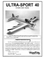
ULTRA-SPORT 40
INSTRUCTION BOOK
PLEASE READ THROUGH THIS INSTRUCTION BOOKLET IN ITS ENTIRETY BEFORE BEGINNING ASSEMBLY. IT CONTAINS IMPORTANT INSTRUCTIONS AND WARNINGS CONCERNING THE
ASSEMBLY AND USE OF THIS MODEL.
WARNING! THIS IS NOT A TOY!
This R/C kit and the model you will build is not a toy! It is capable of serious bodily harm and
property damage. IT IS YOUR RESPONSIBILITY AND YOURS ALONE - to build this kit
correctly, properly install all R/C components and flying gear (engine, tank, pushrods, etc.) and to test
the model and fly it only with experienced, competent help in accordance with all safety standards and
common sense as set down in the Academy of Model Aeronautics Safety Code. It is suggested that you
join the AMA to become properly insured before you attempt to fly this model. IF YOU ARE JUST
STARTING R/C MODELING, CONSULT YOUR LOCAL HOBBY SHOP OR WRITE TO THE
ACADEMY OF MODEL AERONAUTICS TO FIND AN EXPERIENCED INSTRUCTOR IN
YOUR AREA.
Academy of Model Aeronautics
1810 Samuel Morse Dr.
Reston.VA 22090
(703)435-0750
POBOXW
URBANA ILLINOlS
61601
36720t9
TABLE OF CONTENTS
INTRODUCTION . . . . . . . . . . . . . . 3
Precautions . . . . . . . . . . . . . . . . . . . . . 3
Abbreviations . . . . . . . . . . . . . . . . . . . 3
Decisions You Must Make . . . . . . . . . 4
Other Items Required . . . . . . . . . . . . . 4
Die Patterns . . . . . . . . . . . . . . . . . . . . 5
Supplies and Tools Needed . . . . . . . . . 6
Types of Wood . . . . . . . . . . . . . . . . . . 6
GET READY TO BUILD . . . . . . . . 6
Tail Feathers . . . . . . . . . . . . . . . . . . . . 6
Fin and Rudder . . . . . . . . . . . . . . . . . . 6
Stabilizer and Elevator . . . . . . . . . . . . 7
WING . . . . . . . . . . . . . . . . . . . . . . . . 9
Wing Panels . . . . . . . . . . . . . . . . . . . . 9
Join the Wing Panels . . . . . . . . . . . . . 14
Install Aileron Torque Rods . . . . . . . . 14
Sand "Flats" on LE and TE . . . . . . . . 15
Fiberglass the Center Section . . . . . . . 15
Install the Wing Tips . . . . . . . . . . . . . . 16
Install the Ailerons . . . . . . . . . . . . . . . 17
Install Wing Dowels . . . . . . . . . . . . . . 18
Install Wing Bolt Plate . . . . . . . . . . . . 18
Fill Landing Gear Slots . . . . . . . . . . . 18
Installing Retracts . . . . . . . . . . . . . . . . 19
FUSELAGE ASSEMBLY . . . . . . . . 19
Preparing Fuse Sides . . . . . . . . . . . . . 19
Assemble Lower Fuselage . . . . . . . . . 21
Drill Engine Mount . . . . . . . . . . . . . . 22
Install Servos and Pushrods . . . . . . . . 22
Install Bottom Sheeting . . . . . . . . . . . 24
Mount the Wing to the Fuse . . . . . . . . 24
Fitting Fuel Tank, Fuelproofing . . . . . 26
Install Turtle Deck . . . . . . . . . . . . . . . 27
Assemble the Nose Section . . . . . . . . 28
FINAL ASSEMBLY . . . . . . . . . . . . . 30
Sand the Fuselage . . . . . . . . . . . . . . . . 30
Install Wing Fairings . . . . . . . . . . . . . . 31
Install Wing Fillets . . . . . . . . . . . . . . . 32
Shape the Fin Fillets . . . . . . . . . . . . . . 33
Mount Stabilizer and Fin . . . . . . . . . . 34
Install Servos, Horns & Pushrods .... 35
Control Surface Throws . . . . . . . . . . . 36
FINISHING . . . . . . . . . . . . . . . . . . . . 3 6
Additional Fuelproofing . . . . . . . . . . . 36
Seal Off Cockpit . . . . . . . . . . . . . . . . . 37
Prepare the Canopy . . . . . . . . . . . . . . . 37
Balance the Airplane Laterally . . . . . . 37
Final Sanding . . . . . . . . . . . . . . . . . . . 37
Covering . . . . . . . . . . . . . . . . . . . . . . . 37
Glue the Hinges . . . . . . . . . . . . . . . . . 38
Install the Pilot . . . . . . . . . . . . . . . . . . 39
Glue Canopy in Place . . . . . . . . . . . . . 39
Wing Seating . . . . . . . . . . . . . . . . . . . 39
Re-install Engine & Radio . . . . . . . . . 39
Balance Your Model . . . . . . . . . . . . . . 39
Final Hookups and Checks . . . . . . . . . 40
PRE-FLIGHT . . . . . . . . . . . . . . . . . . 4 0
Charge the Batteries . . . . . . . . . . . . . . 40
Find a Safe Place to Fly . . . . . . . . . . . 4 0
Ground Check the Model . . . . . . . . . . 41
Range Check Your Model . . . . . . . . . . 41
AMA SAFETY CODE . . . . . . . . . . . 4 2
General . . . . . . . . . . . . . . . . . . . . . . . . 42
Radio Control . . . . . . . . . . . . . . . . . . . 42
FLYING.......................42
Takeoff . . . . . . . . . . . . . . . . . . . . . . . . 4 2
Flying . . . . . . . . . . . . . . . . . . . . . . . . . 42
Landing . . . . . . . . . . . . . . . . . . . . . . . 42
Caution . . . . . . . . . . . . . . . . . . . . . . . . 43
TRIM INSTRUCTIONS . . . . . . . . . 43
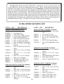
PARTS LIST . . . . . . . . . . . . . . . . . . . 4 6
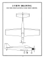
2-VIEW . . . . . . . . . . . . . . . . . . . . . . . 4 8
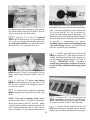
Please inspect all parts carefully before starting to build! If any parts are missing, broken or defective, or if you have any questions about building or flying this airplane, please call us at (217) 367 - 2069
and we'll be glad to help. If you are calling for replacement parts, please look up the part numbers and
the kit identification number (stamped on the end of the carton) and have them ready when calling.
2
4.
You must properly install all R/C and other components so that the model operates properly on the
ground and in the air.
INTRODUCTION
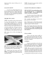
Congratulations! Thank you for purchasing the
Great Planes Ultra Sport 40! Jim Feldmann's original
design Ultra Sport 60 was featured as a construction
article in the August, 1989 issue of RC Modeler magazine, and has been hailed by many as "the best sport
flying airplane ever''! The design starts with the legendary "Kaos" wing planform, and features modem styling and state-of-the-art construction techniques. The
result is an ultra-stable, ultra-smooth flying airplane that
does what you want it to, no more and no less.
5.
You must test the operation of the model before
the first and each successive flight to insure that all
equipment is operating, and you must make certain that
the model has remained structurally sound. Be sure to
check the nylon clevises and horns often, and replace if
they show signs of wear.
6.
You must fly the model only with the competent
help of a well experienced R/C pilot if you arc not
already an experienced and knowledgeable R/C pilot at
this time.
The Ultra Sport 40 is easy to build, totally predictable, smooth-flying and has very docile stall characteristics, making it the ultimate sport airplane for the modeler
who wants to fly with a higher degree of precision. Because it naturally tracks through maneuvers better than
other sport airplanes, you' 11 fly better when you' re flying
an Ultra Sport 40.
Note: We, as the kit manufacturer, can provide you
with a top quality kit and great instructions, but
ultimately the quality and fly ability of your finished
model depends on how you build it; therefore, we
cannot in any way guarantee the performance of
your completed model, and no representations are
expressed or implied as to the performance or safety
of your completed model.
This is not a beginner's airplane! While the
Ultra Sport 40 is easy to build and flies great, we must
discourage you from selecting this kit as your first R/C
airplane. It is fast, highly maneuverable, and lacks the
self-recovery characteristics of a good basic trainer
such as the Great Planes PT Series airplanes. On the
other hand, if you have already learned the basics of R/
C flying and you are able to safely handle an "aileron
trainer" airplane such as the Great Planes Trainer
Series or Big Stick Series airplanes, the Ultra Sport 40
is an excellent choice.
Remember: Take your time and follow
directions to end up with a well-built model that
is straight and true.
INSTRUCTIONS IN BOXES LIKE THIS
ARE VERY IMPORTANT AND SHOULD
BE FOLLOWED CAREFULLY.
PRECAUTIONS
1. You must build the plane according to the plans
and instructions. Do not alter or modify the model as
represented by the plans, as doing so may result in an
unsafe or unflyable model. In a few cases the plans and
instructions may differ slightly from the photos. In those
instances you should assume the plans and written instructions are correct.
COMMON ABBREVIATIONS USED IN
THIS BOOK AND ON THE PLANS:
Elev = Elevator
Fuse = Fuselage
LE = Leading Edge (front)
LG = Landing Gear
Lt = Left
Ply = Plywood
Rt = Right
Stab = Stabilizer
2.
You must take time to build straight, true and
strong.
3.
You must use a proper R/C radio that is in first
class condition, the correct sized engine and correct
components (fuel tank, wheels, etc.) throughout your
building process.
TE = Trailing Edge (rear)
Tri = Triangle
" = Inches
3
DECISIONS YOU MUST MAKE NOW
ENGINE AND MOUNT SELECTION
The recommended engine size range is as
follows:
.40 - .46 cubic inch displacement 2-cycle
.60* - .70 cubic inch displacement 4-cycle
*NOTE: Although not included in the
above engine size range, the OS MAX 48 SURPASS also provides sufficient power to fly this
airplane.
NOTE: If you choose to power your Ultra
Sport 40 with a 4-cycle engine, keep in mind that
the RPM of your engine will be considerably
less than that of a 2-cycle engine; therefore, you
should select a higher pitch propeller to keep
the speed and overall performance roughly
equivalent to that of a 2-cycle engine. For
example, a 10x6 or 10x7 prop would be used
with a .40 (2-cycle) engine; but an 11x9 or
10x10 prop may be the best choices for a 4-cycle
engine.
The engine you select will determine how
you build the fuselage, so it is important that you
have the engine close at hand while building.
This kit includes a Great Planes MM40
engine mount that fits most .40 - .45 (2-cycle)
engines (only slight modification of this mount
is required to mount the OS40SF and OS46SF).
If you are installing an OS48 SURPASS
(4-cycle), you may purchase a Great Planes
MM60 mount. If you are planning to install the
OS70 SURPASS (4-cycle), you may purchase
the Great Planes MM60L mount. If you prefer,
you may purchase a custom engine mount for
your engine, or you may choose to install shockabsorbing rubber-cushioned mounts.
LANDING GEAR CONFIGURATION
The Ultra Sport 40 may be built with either
a "taildragger" or "tricycle" landing gear
configuration, and a retractable main gear
may be installed if you want to really "clean
up" this airplane for ultra-smooth and precise
aerobatics.
There is not. however, room for a nose gear
retract; therefore, if you want retracts, you'll
have to use the "taildragger" configuration.
OTHER ITEMS REQUIRED
• Four-channel radio with 4 servos (additional channel and
retract servo required if retracts are being used).
• Propellers (see engine instructions for recommended
size)
Spinner (2-1/4" diameter)
Fuel Tank (10 or 12 ounce)
Main Wheels - 2 (2-1/2" dia. for fixed gear. 2-1/4" for
retract)
Nose Wheel -1 (2-1/4" diameter, required fortrike only)
Tail Wheel - 1 (1" diameter, required for taildragger
only)
• 5/32" Wheel Collars - 4 or 6
• 3/32" Wheel Collars - 2 (required for taildragger only)
• Iron-on Covering Material
• Silicone Fuel Tubing
• Wing Seating Tape (or silicone sealer... see instructions)
• Latex Foam Rubber Padding (1/4" thick)
• Dubro "E-Z Connectors" (or equivalent) - 2
• Main Gear Retracts (Dave Brown 2-Gear Main, or
equivalent)
• Plastic Pilot (Williams Bros. 2" scale) (larger 2-5/8"
scale pilot may be used, but requires modification)
4
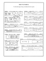
DIE PATTERNS
Use this drawing to help you identify the die cut parts.
5
SUPPLIES AND TOOLS NEEDED
GET READY TO BUILD
2 oz. Thin CA Adhesive
2 oz. Medium or Thick CA Adhesive
2.5 oz. 30-Minute Epoxy
Hand or Electric Drill
Drill Bits: 1/16". 5/64", 3/32", 7/64", 1/8", 9/64", 5/32",
13/64". 7/32", and 1/4"
Sealing Iron
Heat Gun
Hobby Saw (Xacto Razor Saw)
Xacto Knife, #11 Blades
Pliers
Screw Driver
T-Pins
Straightedge
Masking Tape
Sandpaper (coarse, medium, fine grit)*
T-Bar Sanding Block, or similar
Waxed Paper
Lightweight Balsa Filler
1/4-20 Tap, Tap Wrench
Vaseline Petroleum Jelly
Isopropyi Rubbing Alcohol (70%)
Dremel Moto Tool or similar (optional)
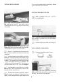
1. Unroll the plan sheet. Re-roll it inside out to make
it lie flat. NOTE: You may cut the plan into two sections
("wing" and "fuselage"), by cutting along the "cut
line'' shown on the plan.
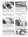
2. Remove all parts from the box. As you do, figure
out the name of each part by comparing it with the plans
and the parts list. Using a felt tip pen, write the part name
or size on each piece to avoid confusion later. Use the
die-cut patterns shown on page 5 to identify the die-cut
parts and mark them before punching out. Save all
scraps. If any of the die-cut parts arc difficult to punch
out, do not force them! Instead, first cut around the parts
with an Xacto knife. Afterpunching out the die-cut parts,
use your T-Bar or sanding block to lightly sand the edges
to remove any die-cutting irregularities.
3. As you identify and mark the parts, separate them
into groups, such as fuse (fuselage), wing, fin and stab
(stabilizer), and hardware.
*NOTE: On our workbench, we have four 11" TBar sanders, equipped with #50, #80, #100 and
#150-grit sandpaper. This setup is all that is
required for almost any sanding task. We also keep
some #320-grit wet-or-dry sandpaper handy for
"TAIL FEATHERS"
finish sanding before covering.
BUILD THE FIN AND RUDDER
1. Find the following parts: 1/4" balsa fin front,
fin rear, rudder front, rudder rear and rudder bottom. Compare the parts to the plans to make sure you
have the correct parts. Also find the 1/4 "x 9/16" x 15"
balsa stick, and the 1/8" x 1/4" x 12" balsa stick.
TYPES OF WOOD
2. Cut the 1/4" x 9/16" x 15" balsa stick into three
pieces having lengths of: 5-1/4", 4-3/4" and 4-3/4". The
5-1/4" lengthis the fin tip. Mark the 4-3/4" pieces "stab
tip".
BALSA
BASSWOOD
3. Cut the 1/8" x 1/4" x 12" balsa stick into 5 pieces
having lengths of: 2-3/4", 2-5/8", 2-5/8", 1-5/8" and
1-5/8". The 2-3/4" length is the rudder end. The
remaining pieces are the elevator ends.
PLYWOOD
6
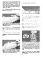
10. If you are building a "taildragger", check the
plans and mark the location of the tailgear on the rudder.
Drill a 7/64" hole in the rudder, and groove the rudder
leading edge to accept the tailgear wire and the nylon
tailgear bearing.
4. Working on a flat surface covered with waxed
paper, glue the fin front to the fin rear, then glue on the
fin tip. Sand the front of the fin tip to blend with the fin.
as shown on the plan.
5. Using a T-bar or sanding block, sand both sides
of the fin smooth. Then sand the leading edge and top
edge to a rounded shape, as shown on the plan. Draw a
centerline along the trailing edge of the fin to mark the
hinge line.
BUILD THE STABILIZER AND
ELEVATORS
6. Glue the rudder front to the rudder rear, then
glue on the rudder bottom and rudder end.
7. Draw a centerline all around the edges of the
rudder (This will help to maintain symmetry when
sanding).
1. Find the following parts: 1/4" balsa stab front,
stab rear and elevators. You'll also need the 1/4" stab
tips and 1/8" elevator ends that you previously cut, and
the 1/8" wire elevator joiner.
8. Using a sanding block and coarse (50 or 80-grit)
sandpaper, sand both sides of the rudder to a taper as
shown on the plans. The trailing edge should end up
approximately 3/32" wide and have a rounded shape.
(Do not sand to a sharp edge). Sand the bottom edge to
a rounded shape. Sand the leading edge to a' 'V-shape''
as shown on the plan.
2. Glue the stab front to the stab rear. Then glue
on the stab tips. Sand the front of the stab tips to blend
with the stab.
9. Hold the fin and rudder together and mark the fin
tip at the rudder trailing edge. Cut off the fin tip and sand
it to match the rudder as shown on the plan.
4. Sand both sides of the stab smooth, then sand the
leading edge and tips to a rounded shape. (Leave the
3. Glue the elevator ends to the elevators and sand
to blend.
7
center portion of the LE square). Draw a centerline
along the trailing edge of the stab to mark the hinge line.
5. Draw a centerline all around the edges of the
elevators.
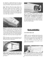
9. Accurately drill holes in the elevators for the
1/8" wire joiner. Begin by drilling a 1/16" or 5/64" pilot
hole, then drill the final hole to a depth of 7/8" with a
9/64" drill bit. (The hole is drilled slightly oversize to
allow for positioning, and to create a hard epoxy
"sleeve" around the wire).
6. Sand both sides of the elevators to a taper as
shown on the plans. The trailing edge should end up
approximately 3/32" wide and have a rounded shape (do
not sand to a sharp edge). Sand the leading edge to a "Vshape" as shown on the plan.
10. Using an Xacto knife, sharpen the inside of one
end of a 1/8" diameter brass tube and use it to cut grooves
in the leading edge of the elevators to accept the joiner
wire.
7. Temporarily tape the elevators to the stab, providing 1/16" clearance between the elevator end and the
stab tip.
11. Roughen the joiner wire with coarse sandpaper,
then clean the wire thoroughly with alcohol to remove
any oily residue.
8. Lay the 1/8" wire elevator joiner in place on the
elevators and mark its outline using a fine point felt-tip
pen.
12. Trial fit the joiner wire into the elevators, then
glue it in using 5-minute or 30-minute epoxy. When
gluing, lay the elevator leading edges along a straightedge to insure perfect alignment.
8
from your local hobby dealer). Many expert
modelers prefer to use a wing jig for high
performance airplanes, as it helps to insure a
straight, warp-free wing, especially if you do not
have a workbench or building board that is perfectly
flat. If you choose to use the Wing Jig, please read
the instructions that are included with the jig before
beginning.
INSTALL THE HINGES (Do not glue)
NOTE: One-piece molded polypropylene hinges
are supplied in this kit. If you choose to use these
hinges or the "pinned"-type hinges, you may cut
the hinge slots at this time. However, if you choose
to use the one-piece hinges that are paper covered
for CA glue installation, you may wait until after
covering before cutting the hinge slots.
BUILD THE WING PANELS
1. Lay the rudder and elevators on the plan and
mark the hinge locations. Place the rudder against the
fin TE and transfer the marks over to the fin. Place the
elevators against the stab TE and transfer the marks over
to the stab.
NOTE: It will be helpful to build the wing on a
piece of "Celotex" or other semi-soft (and flat)
surface, into which you may easily stick pins to
firmly hold down the wing parts while building, to
avoid warps.
1. Tape the plan to your flat work surface, and
cover the wing drawing with waxed paper (so you won't
glue the wing to the plan!). NOTE: If your work space
is limited, you may cut the left and right wing half
drawings apart.
CAUTION!!!: You must use extreme care
when cutting hinge slots with an Xacto
knife, to avoid cutting yourself! If the balsa
part breaks while you are pushing on the
knife, the blade could go into your hand
before you know it! A good precaution is to
wear leather gloves while performing the
following steps.
2. The shaped and notched wing leading edges
(LE) and trailing edges (TE) are fastened together by
thin strips of balsa. Separate them by folding until the
balsa breaks. Sand away the excess balsa that remains
along the edges after breaking them apart, using a T-bar
with 100-grit sandpaper.
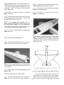
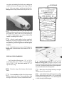
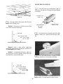
3. Before using the 1/4" x 3/8" x 27-1/4" hard balsa
spars, examine them carefully for possible imperfections. Look for knots, soft spots, diagonal grain and any
other imperfections. If possible, position each spar so the
imperfections (if any) are on the outer half of the wing
panel (toward the tip), where they will be least affected
by high stress. If the spars are warped slightly, try to
"balance them out" by installing the warped spars in
opposite directions (see sketch).
2. Cut the hinge slots on the accurate centerlines
which you previously drew, using an Xacto knife or a
hinge slotting fork and hook. (See Step 7 on Page 17)
3. IMPORTANT! Condition or "break-in" the
hinges by folding them back and forth several times.
4. Insert the hinges into the slots and trial fit the
rudder and elevators in place on the fin and stab. Do not
glue the hinges until after you have covered the
model.
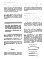
TWO WARPED SPARS INSTALLED
THIS W A Y WILL R E S U L T IN A
STRAIGHT WING
WING
TWO WARPED SPARS INSTALLED
THIS W A Y WILL RESULT IN A
WARPED WING
NOTE: The following instructions explain how to
build the wing directly on the plans. An alternative
method is to use a Great Planes Wing Jig (available
9
4. Find the 1/8" x 3/8" x 13-3/8" basswood spar
doublers. Sand one end of each spar doubler to a taper
as shown in the " Wing Spar Detail" on the plan. Glue
the spar doublers to the spars, and sand off any excess
glue.
NOTE: Follow steps 9 through 34 to build
the RIGHT wing panel, then repeat these
steps to build the LEFT wing panel.
5. Carefully punch out all the die-cut 3/32" balsa
wing ribs. Sand the edges slightly to remove any diecutting irregularities.
NOTE: If you will be installing a retractable
landing gear, disregard Steps 6 and 7.
6. Note that the wing plan shows two alternate
locations for the main landing gear blocks. Note also that
Ribs W-2, W-3 and W-4 have partial cutouts foreach of
the two locations. If you are building your plane as a
taildragger, cut out the front notches in these ribs. If
you are building your plane with a tricycle gear, cut out
the rear notches. (If you will be installing retracts, do not
cut out any of the notches).
9. Pin one of the spars to the plan with the spar
doubler up and toward the root. NOTE: The spars are
cut slightly too long. Center the spar on the plan so an
equal amount protrudes on both ends.
7. Glue the die-cut 1/16" ply landing gear doublers to ribs W-2, W-3 and W-4. Be sure to glue them
to the correct side of the ribs, as shown on the plan (make
a right and a left set). Sand the doublers even with the
edge of the ribs.
10. Place the ribs on the spar in their approximate position, but do not glue. NOTE: Make sure ribs
W-2, W-3 and W-4 are installed with the LG notches
down, and W-l is installed with the servo opening
pointing up.
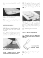
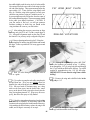
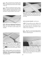
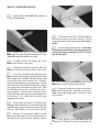
8. Prepare the leading edge sheeting as follows:
Edge glue the 3/32" x 1/2" x 7-1/2" balsa sheets to the 3/
32" x 3" x 27-1/4" balsa sheets as shown here...
CUT FIRST SLOT TO
ANGLE OF DIHEDRAL
GAUGE
Now measure and mark the balsa sheeting (see
sketch below), then cut the angle in the sheeting, cutting
along a metal straightedge for accuracy.
NOTCHED LEADING
EDGE
11. Notice that all notches in the LE and TE are
vertical. However, rib W-l will be installed at a slight
angle using the Dihedral Gauge. Therefore, you should
now modify the notch for W-1 by cutting it to the angle
of the rib. You may determine the approximate angle of
the cut by holding the Dihedral Gauge (DG) against the
LE as shown above.
10
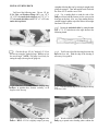
12. Insert the rear ends of the ribs into the
notches in the TE. then block up the TE with the 1/4"
balsa TE Jig supplied. NOTE: The narrow end of the
TEjig is at rib W-11. Pin the jig to the building surface.
the TE, LE and bottom spar. Glue all other ribs to the
LE and bottom spar.
17. Glue the top sparin place, making sure you
do not change the angle of W-1.
13. PintheTEtotheTEJig.makingsuretheribs
line up with the plan.
14. Glue ribs W-2 through W-11 to the TE.
(Apply glue sparingly, to avoid gluing the TE to the TE
Jig).
15. Insert the front ends of the ribs into the
notches in the LE. NOTE: Position the LE as shown in
the sketch.
18. Glue the pre-cut 3/32" balsa vertical grain
shear webs to the rear edge of the spars in all rib bays
except between ribs W-1 and W-2. NOTE: You may
wish to trial fit, mark, and trim each web before gluing
in. NOTE: The webs must be securely glued to the
spars, but it is not necessary to glue the webs to the ribs.
CENTER L.E. VERTICALLY
ON FRONT OF RIBS
L.E.
16. Make sure the ribs are fully down on the plan
and all ribs are inserted into the LE notches. Angle rib W1 slightly using the dihedral gauge (DG). Glue W-1 to
19. You will now make a "pocket" for the
1/16" ply dihedral brace by installing a 3/32" balsa
11
web 1/16" behind the spars. Sand one of the 3/32" x 2"
x 2-5/8" balsa horizontal grain webs for a good fit
between W-l and W-2. Using the 1/16" ply dihedral
brace as a temporary spacer, glue the 3/32" web to W-l
and W-2.
the following step and go through a "dry run*
before actually gluing.
20. Glue the die-cut 1/8" ply front web to the
front edge of the spars between ribs W-l and W-2.
24. Position the leading edge sheeting at the rear
edge of the notched LE so there is an equal amount
protruding on both ends of the wing. Using thin CA, glue
the front (beveled) edge of the leading edge sheeting to
the back edge of the leading edge. Now wet the top
surface of the sheeting so it will bend easier. Apply thick
CA glue to the top edge of the ribs and to the front half
of the spar, then immediately bend the sheeting down
onto the ribs and spar. Hold the sheeting down with
masking tape, pins and your hands until the glue has set.
NOTE: In the next steps, maintain straightness
by keeping the wing down on the flat surface and
on the TE Jig.
21. Lightly sand the tops of the ribs to blend
with the notched trailing edge; then glue one of the 3/32"
x 1-3/8" x 27-1/4" balsa trailing edge sheets in place.
NOTE: The edge of the TE sheet may not be exactly
straight, but just position the sheet so it slightly overlaps
the TE, and any overlap can be sanded off later.
22. Before applying the leading edge sheeting in
the next step, use your T-bar to lightly sand off the edges
of the shear webs and smoothly blend the ribs to the spar.
23. Prepare the 3/32" balsa leading edge sheet ing by sanding the front edge to a slight bevel so it will
fit snugly against the back of the leading edge.
NOTE: It will be helpful to have the following
items handy for the next step... thin CA, thick CA,
a wet cloth, masking tape and T-pins. Read through
25. Using the 3/32" x 3" x 8-1/4" balsa sheets,
glue the top center section sheeting in place as shown on
the plan.
NOTE: If you are installing retracts, disregard
steps 26 through 29.
26. Remove the wing from the building board
and trial fit the long grooved hardwood LG block into
the notches in dbs W-2, W-3 and W-4 (see the landing
12
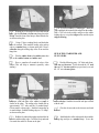
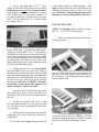
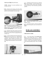
Photo of finished wing with retract mechanism removed.
the bottom of the wing, in the location shown on the
plan. Lock and strengthen the joints between the
1/4" ply rails and the 1/16" ply rib doublers by
gluing 1/4" balsa triangle stock to these joints. You
should also now do some planning and trial fitting of
the retract and pushrod, customizing the installation
as necessary to accommodate your retracts.
Installing retracts requires careful planning and
a lot of trial fitting; therefore, you should take the
time now to plan out your installation.
gear detail drawing on the wing plan for proper positioning). File the notches if necessary for a good fit. Now use
epoxy to securely glue the block in place.
27. Epoxy the 7/16" x 5/8" x 7/8" hardwood
block to the LG block and to the 1/16" ply doubler on rib
W-2. as shown on the plan and in the photo, then epoxy
the small hardwood block to the other end of the LG
block and to the 1/16" ply doubler on rib W-4.
31. With the wing upside down, again use the
TE jig to support the TE. Then install the bottom TE
sheeting, LE sheeting and Center Section sheeting, cutting and fitting the sheeting around the LG block as
necessary. IMPORTANT NOTE: To insure a
straight wing, you must pin or weight the TE securely
down on the TEjig while the bottom sheeting is glued
in place!
28. Drill a 5/32" hole down through the grooved
LG block and the 7/8" block. Line up the drill so you are
drilling straight down through the middle of the 7/8"
block.
29. Trial fit the 5/32" diameter main landing
gear wire into the landing gear block at this time. Cut or
file the groove and hole in the landing gear block as
necessary for a good fit.
30. Using a razor saw, carefully cut off and sand
all excess sheeting, spars, LE and TE even with W-1 and
W-ll.
32. From the 3/32" x 1/4" x 30" balsa sticks, cut
and glue cap strips to all exposed ribs, top and bottom.
HINT: Foreasierpositioning of the cap strips, firstmark
the location of each rib on the LE and TE sheeting.
NOTE: If you will be installing retracts, now is
the time to glue in the 1/16" ply die-cut rib doublers
to the front portion of ribs W-3 and W-4. (Make
sure the front rib doublers are on the outboard side
of W-3 and the inboard side of W-4). This is also the
time to install the 1/4" ply retract mounting rails on
33. Trim the sheeting flush with ribs W-l and
W-11 and sand the entire wing panel smooth. Sand the
leading edge to smoothly blend with the LE sheeting (see
13
the rib cross-sections on the plan for the desired LE
shape).
3. Mix up a batch of 30-minute epoxy and push
some into the dihedral brace slots. Smear epoxy on the
spar ends, and on both sides of the 1/16" ply dihedral
brace. Slide the dihedral brace in place, push the wing
panels together and immediately proceed to the next
step.
34. Mark and cut out a 1/16" slot in W-l just
behind the spars, for the dihedral brace.
35. Now go back and repeat Steps 9 through 34 to
build the left wing panel.
4. With the wing tips blocked up 1 -inch, carefully
align the LE and TE of both wing panels at the center and,
while holding them in correct alignment, apply thin CA
glue to "lock" the panels together. Do not apply CA
glue to any area that is already coated with epoxy.
Allow the epoxy to fully harden before disturbing the
wing.
JOIN THE WING PANELS
NOTE: Read steps 1 through 4, then make a "dry
run" through these steps before actually
proceeding.
5. Sand the wing joint smooth all around.
1. Lay a piece of waxed paper down at the center of
the wing, place the two wing panels together at the center,
and block up both wing tips 1-inch. Sand the wing
panels at the center so they will fit together without a gap.
INSTALL AILERON TORQUE RODS
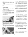
1. Roughen the short end of the aileron torque
rods with 100-grit sandpaper, and file the same end to a
wedge shape.
FILE END TO
WEDGE SHAPE
2. Trial fit the 1/16" ply dihedral brace to make
sure it will readily slide into place.
2. Roughen the surface of the plastic bearing tubes
with 100-grit sandpaper.
NOTE:
30-minute epoxy is strongly
recommended for the wing joining process.
14
3. Clean the torque rods and bearing tubes with
alcohol.
SAND "FLATS" ON LE AND TE
4. Find the two grooved, tapered balsa center
trailing edge pieces. Lay them on the plan, mark and cut
them off to match the plan for length and angle at the
centerline.
1. Study the wing plan near the wing centerline.
Note that the center portion of the LE and TE must be
sanded flat.
2. Sand approximately 5/32" into the LE at the
centerline, and approximately 3/32" into the TE at the
centerline. (The flats will end up approximately 4-1/2"
wide at the LE, and 2" wide at the TE).
5. Trial fit the torque rods into the center TE pieces.
Determine from the plan where to cut the clearance
notches, which will permit the torque rod horns to travel
freely. Also cut small clearance notches in the wing TE.
Note: The torque rod horns must exit the TOP of the
wing!
FIBERGLASS THE CENTER SECTION
6. Slide the plastic bearings toward the threaded
end of the torque rods, then use a toothpick to apply a
small amount of petroleum jelly to the ends of the plastic
tubes (to help prevent glue from getting inside and
locking up the torque rods).
NOTE: Because of the high stresses in the center
of this wing, fiberglass reinforcement is
REQUIRED. Please do not omit this important
section!
7. Use 5-minute epoxy or CA to glue the plastic
bearing tubes into the grooves in the center TE pieces.
Wipe off any excess glue and allow it to harden.
NOTE: If you have previous experience with
applying fiberglass, feel free to use your favorite
method, providing that it results in a strong bond
between the glass cloth and the wood. If this is your
first time, we offer the following suggested method,
which is the fastest and easiest we have seen.
1. Make location marks for the fiberglass reinforcement cloth, 1-1/2" each way from the wing centerline.
8. Trial fit the trailing edge/torque rod assemblies
onto the wing trailing edge. Sand the center trailing edge
pieces slightly where they join, for a good fit. Glue these
pieces in place with epoxy. HINT: Use masking tape to
hold these pieces to the wing TE. to aid in correct positioning.
2. Trial fit the 3" wide fiberglass cloth in place.
You can use a scissors or a paper punch to cut holes in the
glass cloth for the aileron torque rod horns.
3. Wrap small pieces of masking tape around the
threaded portion of the aileron torque rods to protect
them from the spray adhesive in the next step.
15
4. Spray a very light mist of 3M "77" Spray
Adhesive on the center section in the area to be glassed.
Hold the spray can at least 12" away from the surface
when doing this to avoid a heavy buildup. The purpose
of this is only to give the wood a little "tackiness". If
you apply too much spray it could result in a poor glue
bond. Allow the spray to dry for 5 minutes before
proceeding to step 5.
a T-bar sander with 80 or 100-grit sandpaper. Also,
lightly sand the surface of the glass cloth with a piece of
sandpaper held in your fingers to remove any rough
spots. WARNING: When sanding fiberglass, wear a
dust mask to avoid breathing airborne glass fibers.
INSTALL WING TIPS
NOTE: The wing tips will be cut and carved from
the 7/8" x 1-7/16" x 8-3/4" balsa blocks.
1. Draw a centerline on the ends of the wing and on
the wing tip blocks.
5. Beginning at the trailing edge, lay the glass tape
in place on the wing. Gently press the cloth in place,
working out all the wrinkles. The "77" spray adhesive
should hold the cloth down to the surface, but will permit
you to lift and reposition the cloth if you make a mistake.
Keep working forward along the top of the wing, around
the leading edge, and along the bottom of the wing,
ending at the trailing edge. Do not attempt to wrap the
glass cloth around the trailing edge.
6. Working outdoors or in a very well-ventilated
area apply thin CA glue to the glass cloth. Begin by
running a bead of glue down the center of the glass cloth
strip, then continue applying the glue in lines until all the
cloth has been secured. Run the thin CA out 1/4" beyond
the edges of the glass cloth to help protect the balsa
sheeting when sanding later. WARNING: This operation produces a larger than normal quantity of CA
fumes, so adequate ventilation is a must!
2. Securely glue a wing tip block to the left end of
the wing, and tack glue the other wing tip block to the
right end of the wing, lining up the centerlines you
previously drew. You will later break only the right tip
loose and hollow it out.
7. Inspect the surface of the glass cloth. If any areas
are not glued down, apply a couple more drops of CA
glue and press down with a piece of waxed paper until the
glue sets.
8. To make sure the glass cloth is fully "wetted
out" and bonded to the balsa, you may apply more thin
CA, a few drops at a time, and spread it out with a piece
of waxed paper.
9. After the glue has set, trim the excess cloth at the
trailing edge with a sharp Xacto knife followed by a
sanding block.
3. Cut, carve and sand the wing tips to the appropriate shape as shown on the plan. HINT: Use 50-grit
sandpaper to speed up this operation. NOTE: Leave the
tips oversize in the area of the ailerons, for now.
10. Carefully sand the edges of the glass cloth with
16
cut a groove in the leading edge of the ailerons to
accept the torque rods. Cut these grooves a little larger
at the beginning, to make room for the torque rod
bearings. Trial fit the ailerons onto the torque rods and
cut or file as necessary until they fit.
4. Cut the right wing tip loose from the wing and
use a Dremel Moto Tool to hollow out the wing tip. (This
will help to compensate for the weight of the engine head
and muffler).
5. Now securely glue the right wing tip in place.
6. Lay the ailerons on the plan and mark the hinge
locations on the ailerons. Place the ailerons against the
wing TE and transfer the marks over to the wing.
INSTALL AILERONS
7. Cut the hinge slots in the ailerons and wing TE
using an Xacto knife. (The suggested procedure is listed
below):
NOTE: Do not glue the aileron hinges until after
your model has been covered.
A. Begin by carefully cutting a very shallow slit in
the trailing edge at the hinge location. This first cut
is to establish your cut in the right place, so concentrate on staying on the centerline and don't cut too
deep!
1. Draw an accurate centerline along the LE of the
tapered balsa ailerons and the wing TE.
2. Check the length of your ailerons against the
actual aileron openings and trim the ailerons as necessary. You should provide approximately 1/16" gap at
each end of the ailerons.
B. Make three or four more cuts in the same line,
going slightly deeper each time. As you make
these additional cuts, work on going straight into the
wood. Continue this process while "wiggling" the
knife handle back and forth until the blade has
reached the proper depth for the hinge.
C. Trial fit the hinge into the slot. If the hinge is
difficult to push in, re-insert the knife and move it
back and forth in the slot a few times to enlarge the
slot.
8. IMPORTANT! Condition or "break-in" the
hinges by folding them back and forth several times.
3. Lay the ailerons in place in the openings, with
the torque rods resting on top of the ailerons. Mark the
torque rod locations on the top of the ailerons.
9. Sand the leading edge of the ailerons to the same
"V"-shape as shown on the wing rib detail drawing.
4. Drill a 7/64" hole in the ailerons at the torque rod
locations, starting at the leading edge centerline and
drilling straight in to the proper depth.
10. Insert the hinges into the slots and trial fit me
ailerons in place on the wing. Do not glue the hinges until after you have covered the wing.
There should be no hinge gap!
NOTE: Now is a good time to finish the wing tips.
Tape the ailerons on in the neutral position, and sand
the wing tips to blend with the ailerons.
5. Use the sharpened 1/8" diameter brass tube to
17
file, or you may sand the dowels down slightly. Do not
glue the dowels in place at this time.
INSTALL WING DOWELS
INSTALL WING BOLT PLATE
1. Mark a centerline on the 1/16" x 3-3/32" x
1-1/2" ply wing bolt plate.
1. Mark a horizontal centerline on the flat which
you sanded on the wing LE. Also mark a vertical
centerline on the die-cut 1/8" ply former F-2A (the Wing
Dowel Plate).
2. Position the wing bolt plate on the bottom of the
wing, and line it up with the wing TE and centerline.
Glue it in place.
3. Sand the wing bolt plate flush with the wing TE.
2. Holding the die-cut 1/8" balsa F-2A on the
leading edge, in the exact center of the wing, mark the
dowel locations through the dowel plate holes.
FILL LANDING GEAR SLOTS
3. Remove F-2A and double check to make sure the
dowel locations are both the same distance from the wing
center joint.
1. Temporarily install the main LG wires.
4. It is important that you now drill the dowel holes
accurately! To insure accurately positioned holes, begin
by drilling small (1/8") holes in the center of the marked
locations. Then gradually increase drill bit sizes until
you have finally drilled the holes to 1/4" diameter. The
final holes you drill must extend 3-1/2" into the wing to
penetrate the front webs. NOTE: Try to drill straight in.
NYLON LANDING
GEAR STRAP
5. Sand one end of each wing dowel to a slightly
rounded shape. This is the end that will be inserted. Do
not sand the other end at this time.
#2X3/8" SHEET
METAL SCREW
2. Using scraps of balsa, fill the ends of the slots in
the notched LG blocks and sand flush with the surface Of
the wing. This will aid in covering later.
6. Trial fit the dowels into the dowel holes, and trial
fit the dowel plate over the dowels. If the dowels fit too
tightly, you may enlarge the holes slightly using a round
18
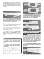
5. Temporarily mount your retract servo and trial
fit all retract components. Test the operation of your
retracts making sure they operate freely and reliably.
Also make sure they "lock" in both the up and down
positions.
INSTALL RETRACTS (OPTIONAL)
NOTE: Hardware for retract installation is not
included in the kit.
1. Study the retract drawings on the plan, and the
installation instructions provided with your retracts, and
plan your retract installation before proceeding.
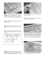
Photo shows finished wing with retract installed.
6. Blend the bottom sheeting as neatly as possible
around the retracts.
7. Use polyester resin or 30 - minute epoxy thinned
with alcohol to fuel proof the entire retract wheel well
cutout
Photo shows finished wing with retract installed.
2. Cut an opening in the bottom LE sheeting for the
retract mechanism. Cut a clearance slot in rib W-3 for the
LG wire. Cut an opening in the bottom LE sheet and in
rib W-2 for the wheel well.
FUSELAGE ASSEMBLY
3. Enclose the wheel well by running vertical grain
1/16" balsa between the bottom and top sheeting; or you
may make the wheel well from an appropriately-sized
styrofoam cup.
PREPARE FUSE SIDES
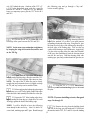
4. Cut out an opening in the center of the wing (in
front of the spars) for your retract servo, and bend and fit
a pushrod to run between the servo and the retract
mechanism. Run the pushrod just under the top LE
sheeting until it passes over the wheel well, then make
two 90-degree bends and connect it to the retract mechanism.
1. Lay one of the shaped 1/8" balsa fuselage sides
in place on the fuselage plan side view. Carefully
position the fuse side so the front edge lines up with the
front ofF-1 on the plan. Tape or pin the fuse side so it
can't move. NOTE: The fuse side may be a little longer
at the rear than indicated by the plan. This is as it should
be.
2. Carefully position the die-cut 1/8" balsa lower
Photo shows finished wing with retract servo installed.
19
front fuse side so the rear edge lines up with the front of
the wing saddle opening on the plan (the rear edge of F2A). Edge glue the lower front fuse side to the fuse side.
NOTE: Use waxed paper under the balsa to avoid gluing
to the plan.
7. Edge glue the appropriate firewall spacers to the
front edge of the fuselage doublers. Note that the spacers
are not the same size. They will automatically set the
engine at the required 2-degrees right thrust.
3. Carefully position the lower rear fuse side so
the vertical front edge lines up with the rear of the wing
saddle opening on the plan (the front edge ofF-4). Edge
glue the lower rear fuse side to the fuse side.
4. Trim off the rear portion of the lower rear fuse
side. making the bottom edge a straight line.
5. Sand the fuse side smooth on both sides using a
T-bar and 100-grit sandpaper, then repeat the above steps
to make the other fuse side.
6. Find the two die-cut 1/8" ply fuselage doublers
and the four die-cut 1/8" ply firewall spacers. Note that
the spacers are marked "2L", "2R", "4L", and
"4R".
Use the #2 firewall spacers if you will be
installing a 2-cycle engine such as the OS Max 40
SF.
8. Carefully position the fuselage doublers on the
fuse sides, making a RIGHT and a LEFT side. The
doubler with the smaller firewall spacer goes on the right
fuselage side... PLAN IT OUT! It is important that the
fuse doubler and fuse side line up along the top edge and
the front of the wing opening. While holding in position, apply thin CA glue around all the notches and
lightening holes, then around the edges. Make sure you
apply sufficient glue so it flows under the doubler to
produce a strong bond. NOTE: The narrow and wide
firewall spacers will automatically position the firewall
to result in 2-degrees of right engine thrust.
9. Glue the tapered balsa tail filler to the aft end of
one of the fuse sides and sand it even with the top and
bottom edges.
Use the #4 firewall spacers if you will be
installing a small 4-cycle engine, such as the OS FS
48 Surpass.
If you will be installing a larger (longer) 4-cycle
engine, such as the OS FS 70 Surpass, do not use
any firewall spacer on the right side, and use the
1/8" x 1/8" x 3-1/8" hardwood stick as a firewall
spacer on the left side.
10. From the 1/4" balsa triangle, cut pieces to fit
20
between the tail filler and the rear of F-4, along the
bottom inside of both fuse sides. Glue in place.
together: Fuse top assembly, fuse sides, die-cut 1/8" ply
F-2, F-3, F-4 and the die-cut 1/8" ply Chin Block Base.
Check the fit of all parts and trim, file or sand as necessary
for a good fit. Pull the aft ends of the fuse sides together
and re-sand the 1/4" triangles if necessary.
11. Sand the aft ends of the balsa triangle to a taper,
which will permit the fuse sides to be pulled together at
the aft end. NOTE: The taper shown in the photo is
approximate and may have to be modified during assembly.
5. Once you have everything fitting properly, reassemble the above parts, using clamps, pins, tape and
weights to hold everything together and flat on the
workbench. Make sure F-2 is pushed as far forward
as possible, and F-4 is pushed as far aft as possible.
There should be waxed paper underneath to prevent
gluing the fuse to the plan. Apply med. or thin CA glue
to the joints, then follow with thick CA glue in any joints
that are not tight fitting.
ASSEMBLE LOWER FUSELAGE
1. Tape the fuselage plan to your workbench and
cover the Fuse Bottom View with waxed paper.
2. Accurately position the die-cut 1/8" ply fuse
top front and the die-cut 1/8" balsa fuse top rear on the
plan. Glue these two parts together by applying thin CA
glue, then follow with thick CA.
6. Find the 1/4" ply wing hold-down block and
trial fit it into the notches in the fuse side doublers,
sanding as necessary for a good fit. Glue the hold-down
block in place securely, using 30-minute epoxy, then cut
pieces of 1/4" balsa triangle and glue them in place above
and below the hold-down block. Sand the triangles flush
with the wing saddle.
3. Glue F-5 and F-6 to the fuse top, positioning
them in the rear of the slots and using a draftsman's
triangle or carpenter's square to set the formers perpendicular to the fuse top.
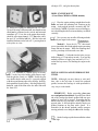
7. Before installing the firewall (F-l), drill F-1 for
your engine mount and install the 6-32 blind nuts. If you
will be using the engine mount supplied in the kit, you
may cut out the F-l drawing from the plans, tape it to
NOTE: The fuselage is assembled upside down.
4. Trial fit (do not glue) the following parts
21
BLIND NUT
aft edges of F-1, and glue them in place.
DRILL ENGINE MOUNT
(Great Planes MM40 or MM60 mounts)
1. Place the engine pointing straight ahead on the
mount and mark the mounting hole locations on the
mount. At the marked locations, accurately drill 7/64"
(or#36) holes. NOTE: If you have access to a drill press,
use it for drilling these holes to insure that they are drilled
vertically.
F-1 and use it as a guide for drilling the four 5/32" holes.
If you will be using a different mount, note that the mount
should not be positioned on the vertical and horizontal
centerlines of F-1, but, due to the engine thrust angle,
should be offset approximately 3/32" above the centerline and 1/8" toward the left side. Drill the holes and
install the blind nuts on the back of F-1, pressing them in
with a pliers or a vise.
2. Now you may use one of the following methods
to attach your engine to the mount:
Method 1: Screw the #6 x 3/4" sheet metal
screws (provided in the kit) through the engine mounting
flange and into the mount. When first installing these
screws, put a drop of oil into each screw hole.
Method 2: Cut threads into the holes you just
drilled using a 6-32 tap and tap wrench. If you use this
method you'll have to supply your own bolts (6-32 x 1"
socket head cap screws) for attaching the engine to the
mount
INSTALL SERVOS AND PUSHROD GUIDE
TUBES
8. Use 30-minute or 5-minute epoxy to securely
glue F-1 to the fuse sides, holding with clamps or tape
until the glue has firmly set. NOTE: Before the glue
sets, double check to make sure F-1 is properly aligned
with the top and bottom edges of the fuselage, and fully
back against the firewall spacers. After the glue has fully
hardened, sand off the front of the fuse sides flush with
the front of F-1.
NOTE: Although you may choose to wait until
later, this is the best time to install the pushrod
guides, because the fuselage is wide open and it is
very easy to work inside.
IMPORTANT: Before proceeding, plan your
servo and pushrod installation. Especially note which
side of the fuselage the throttle pushrod and nose gear
pushrod (if any) will be located. Remember that the
throttle arms of2-cycle and some 4-cycle engines arc on
opposite sides. It will be helpful to actually sketch your
pushrod locations on the plans with a pencil. It is
desireable for the throttle pushrod (and the nosegear
steering pushrod) to run along the sides of the fuselage.
1. Set the fuselage upside down on blocks at least
1-inch high.
9. Cut pieces of 1/4" balsa triangle to fit around the
22
6A. Glue the tubes to the fuse sides at the rear
exit points using thin CA glue. Use scraps of 1/8"
balsa to anchor the tubes to F-5. Do not anchor
the tubes to F-4 at this time, to allow for slight
adjustment of their positions later.
2. Trim the 3/16" ply servo rails and temporarily
mount your servos. (NOTE: Depending on the width of
your servos, and the spacing between servos, you may
have to enlarge the opening in the fuse top). Now
securely glue the servo rails to the fuse sides and fuse top.
Lock the rails in place by gluing scraps of 1/8" ply on top
of the rails.
7. Cut off the tubes at the exit points and sand them
flush with the fuse sides using a sanding block.
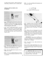
8. Temporarily install the engine mount,
nosegear (and nosegear steering arm if you are building a tricycle configuration).
3. Cut one of the 36" lengths of plastic pushrod
guide tube exactly in half, then sand the outer surface of
the pushrod guide tubes with 100-grit sandpaper to
provide a surface to which the glue will adhere.
5/32" Collar
Steering Arm
Cut off end
6-32 x 1/4" Screw
4. Use an Xacto knife to sharpen one end of a piece
of 3/16" (outside diameter) brass tubing, then use this
tubing to cut the pushrod exit holes (you may use a
3/16" drill bit, but the brass tube method gives a much
neater cut). Determine the location of these holes from
the plans. You may chuck this brass tube in an electric
drill to aid in getting through F-6.
9. Cut 1/4" off the end of the steering arm. then
drill a 3/16" hole in F-l, just above the outer hole of the
arm. NOTE: The drill should be aimed toward the
rudder servo to avoid tight bends in the pushrod.
5. Insert the plastic pushrod tubes through the
holes you just cut and through formers F-6, F-5 and F-4.
your radio installation plan. Temporarily insert
the 34" pushrod wires into the tubes and hold them
in the correct position with tape at the servo end.
Keep the tubes as straight as possible.
23
10. With the engine resting on the mount, plan the
throttle pushrod routing. The pushrod should be located as close as possible to the fuse sides (to allow room
for the fuel tank), and the guide tube should not have any
tight bends. Drill a 3/16" hole in F-l for the throttle
pushrod guide tube.
3. Insert the die-cut 1/8" ply F-2A in place against
the back of F-2 (do not glue).
11. Drill or carve holes in F-2 and F-3 for the guide
tubes, and trial fit
4. Insert the 1/4" wing dowels into the wing so
they stick out only 1/8".
2. Sand the entire wing saddle area lightly until the
fuse side doublers and fuse sides are flush.
12. Sand the plastic pushrod guide tubes with 100grit sandpaper, then glue them in place. Trim and sand
the tubes flush with the front of F-l.
13. Cut the pushrod wires (supplied) to the required lengths and temporarily install the throttle and
nose gear pushrods. NOTE: A 34" wire, threaded one
end, is supplied for the throttle pushrod, and an 18" wire
(no threads) is supplied for the nosegear pushrod.
14. Now remove the pushrod wires, engine, engine
mount and servos.
5. With the fuselage upside down on a flat surface,
trial fit the wing into the wing saddle. If the wing is
slightly too large (front to rear) to fit into the saddle, sand
the rear edge of the saddle and the wing trailing edge
slightly until it fits.
INSTALL BOTTOM SHEETING
1. Sand the bottom of the fuse to remove any excess
glue, and to provide a flat surface for the sheeting.
2. From the 3/32" x 3" x 16" balsa sheet, cut and
glue pieces of cross-grain sheeting to the bottom of the
fuse, beginning at the front of F-4 and running to the aft
end of the fuse.
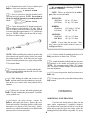
MEASUREMENTS MUST BE EQUAL
3. Sand the edges of the bottom sheeting flush with
6. Carefully align the wing in the saddle as follows:
the fuse sides.
If you have drilled the dowel holes accurately, the
wing should now be centered, side to side. Measure
down from the bottom of both tip ribs to the flat surface.
If the measurements are not equal (within 1/16"), sand
MOUNT THE WING TO THE FUSE
1. Sand the top surface of the fuse to remove any
excess glue so the fuse will lie flat on the workbench.
24
the saddle slightly until the wing sits level in the saddle.
Also measure from the rear comer of each wing tip to the
tail end of the fuselage. These measurements must also
agree within 1/16". If not, shift the wing slightly until
they do. With the wing in this position you may now
check the wing incidence using an "incidence meter'' or
by measuring down to the flat surface from the center of
the leading and trailing edges. The measurements should
be the same (zero degrees incidence). CAUTION: If
your flat surface is not level, you will get erroneous
incidence readings, in which case you should set the
wing incidence the same as your flat surface.
1/16" WING BOLT PLATE
7. After making the necessary corrections to align
the wing, tack glue F-2A to F-2 with a couple drops of
CA. Also make alignment marks on the wing TE and
the front ofF-4 so you may easily re-align the wing later.
DRILLING LOCATIONS
8. Remove the wing and securely glue F-2A in place
by flowing thin CA into the wing dowel holes and around
the edges. Follow up with thick CA in any gaps around
the edges.
12. Holding the wing firmly in place, drill 13/64"
holes at the locations you marked in step 11, drilling
down through the 1/16" ply wing bolt plate and through
the 1/4" ply hold-down block in the fuselage. Try to drill
straight in, perpendicular to the 1/16" ply bolt plate.
IMPORTANT!: Do not allow the wing to move while
drilling!
9. Drill 1/4" holes through F-2 using the holes in
F-2A as a guide.
13. Remove the wing and re-drill the holes in the
wing only to 1/4".
10. Use a pliers to grasp the ends of the wing dowels
and pull them out. Now you may slightly round (or
chamfer) the ends of the dowels for easier insertion into
F-2A. Mix up a batch of 30-minute epoxy, use a long
stick to work some epoxy into the dowel holes, smear
epoxy on the dowels, then re-insert the dowels into the
wing, leaving them protrude 3/8". Wipe away all excess
epoxy, then allow the epoxy to fully harden.
11. Study the wing plan to determine where the wing
bolt holes are to be drilled. By measuring, transfer the
locations to the wing bolt plate on the bottom of the wing.
After marking the bolt locations, replace the wing in the
saddle, and re-align it accurately as in step 6.
14. Use a 1/4-20 tap and a tap wrench to cut threads
in the ply hold-down block in the fuselage.
25
15. Harden the threads in the hold-down block with
thin CA glue, then re-tap the threads after the glue is
completely dry.
1/4 - 20 NYLON BOLT
16. Trial fit the wing to the fuse using the two 1/420 nylon bolts provided. You may cut the bolts off to
their properlength, so they protrude about 1/4" below the
hold-down block in the fuselage.
17. Later you will apply foam wing seating tape or
silicone sealer to the wing saddle. To allow space for
this wing cushion material, you may sand the saddle
slightly in the areas where the wing touches the saddle,
to provide a small gap.
4. Drill two holes (7/32" or size to fit your fuel
tubing) near the top ofF-1 for your fuel tubing vent and
fill lines. The location of these holes will depend
somewhat upon the type of engine you are using, etc. It
is OK to drill the holes in the upper left and upper right
comers, but we prefer drilling both holes in the upper
right comer (as viewed from the rear) for easier access.
18. Sand off the bottom edge ofF-2 and F-2A flush
with the bottom of the chin block base. And, while
you're atit, sand the entire fuse bottom, forward of F-2A,
in preparation for installation of the chin block.
5. Now remove the engine mount and fuelproof
the inside of the fuel tank compartment and the front of
F-1 by brushing on a coat of polyester resin or 30-minute
epoxy thinned with alcohol. NOTE: Later when installing the nose pieces, you will fuelproof the chin block
before installing it.
FIT FUEL TANK, and FUELPROOF TANK
COMPARTMENT
1. Assemble your 10 or 12 oz. fuel tank. We
recommend bending the brass tubes as shown in the
photo to prevent them from cutting through the silicone
fuel lines if pressed against the firewall. (Try not to
"kink" the tubes when bending, however).
6. You may permanently install the fuel tank at
this time, or you may wait until the plane is nearly
completed. If you do it now it will be easier to feed the
fuel lines through F-1, and to make sure there arc no kinks
in the lines; however, you'll have to work around them
while completing the nose. When you install the tank, be
sure to cushion it from vibration and prevent it from
moving by surrounding the tank on all sides (and front)
with latex foam rubber. Leave a few inches of extra fuel
tubing in front of F-l (you can cut off the excess later).
The photo shows how to route the fuel tubing to prevent
kinking.
2. Try sliding the tank in through F-2. If the
opening is not large enough, sand or file the opening until
the tank slides in easily.
3. Temporarily install the engine mount and note
how far the mounting screws protrude into the fuel tank
compartment. Remove the screws and cut them off so
they do not protrude more than 1/8" (to prevent puncturing the fuel tank).
26
INSTALL TURTLE DECK
straighten it during this step by twisting it straight while
gluing the stringers. Trim and sand the ends flush with
the front of F-3A and the rear of F-6A.
You'll need the following parts: Die-cut 1/8" ply
F-3A, F-4A, and Backrest Gauge (BG); two 1/4" x
1/4" x 24" balsa turtle deck stringers; two 3/32" x 3" x
25" balsa turtle deck sides; and the 3/8" x 2" x 24" balsa
turtle deck top block.
4. Use a sanding block to sand the sides of the
stringers to blend with the formers (see the cross-section
drawings on the plan). Also, use a long sanding block to
sand the stringers and the tops of the formers in a straight
line from F-3A to F-6A.
5. Prepare the turtle deck sides by cutting the two
3/32" x 3" x 25" balsa sheets to the angle shown in the
following sketch.
1. Glue the die-cut 1/8" ply "backrest" (F-3A) to
the fuse top, using the' 'backrest gauge'' (BG) to set it at
the correct angle. NOTE: The gauge is used only for
setting the angle (do not glue the gauge in).
6. Trial fit one edge of the sheeting down onto the
top of the fuse side. Sand the edge of the sheeting if
necessary, for a good fit.
2. Glue F-4A, F-5A and F-6A to the fuse top, using
a square to position these formers vertically, at 90
degrees to the fuse top.
7. Glue the bottom edge of the sheeting to the top
of the fuse sides.
3. Glue the 1/4" x 1/4" x 24" balsa stringers to the
formers. HINT: If F-3A is slightly warped, you may
8. Wet the outside surface of the sheeting with a
damp rag to permit easier bending (don t saturate the
27
wood!). Apply thick CA glue to the edges of the formers
and the stringers, then immediately bend the sheeting
around the formers and onto the stringers. HINT: This
requires about 5 sets of "hands," so use several long
pieces of masking tape to pull the sheeting together, then,
working a small section at a time, add CA and press the
sheeting to the stringers.
ASSEMBLE THE NOSE SECTION
9. Trim and sand the sheeting flush with the front
of F-3A and the rear of F-6A.
1. Find the 1/4" x 1/4" x 7-3/4" balsa cockpit sides.
Cut off one end of each stick at an angle to fit the front
edge of the backrest (F-3A).
2. Glue the cockpit sides to the top edge of the fuse
sides and to F-3A. The outside edge of the cockpit sides
should be flush with the outside edge of the fuse sides.
10. Using a long T-bar or sanding block with 80-grit
sandpaper, sand the sheeting and stringers flush with the
top edges of the formers.
3. Sand off the front of the cockpit sides on the
same angle as the front 1-1/2 inches of the fuselage.
4. Attach the engine mount to F-l, and attach the
engine to the mount. Remove the nose gear.
11. Glue the 3/8" x 2" x 24" balsa turtle deck top
block to the tops of the formers, stringers and sheeting,
then trim the ends of the top block flush with F-3A and
F-6A.
HINT: In the next step it will be helpful in keeping
the top block symmetrical if you first mark a
centerline on the top of the top block from front to
back.
5. From a scrap of 1/32" ply, cut four small pieces
and tack glue them to the 1/16" ply spinner ring as
shown, using a very small amount of thick CA (these will
be removed later). IMPORTANT NOTE: If you have
chosen to use shock absorbing rubber "Lord" mounts,
then you must provide more space between the spinner
ring and the spinner backplate to allow for engine movement. A space of approximately 1/8" is probably sufficient.
12. Carve and sand the top block to blend smoothly
with the sheeting (see the cross-section on the plan).
HINT: Use a razor plane and a sanding block with 50grit sandpaper for rough shaping the top block.
28
6. Now center your 2-1/4" diameter spinner
backplate over the spinner ring, and tack glue it to the
1/32" ply spacers.
tube) to drill a hole in the chin block for the nosegear
wire. Insert the drill through the holes in the engine
mount and drill down through the chin block.
7. Slide the spinner ring / spinner backplate assembiy onto the driveshaft and temporarily hold in place with
the prop and prop nut.
13. Temporarily install the nose gear, steering arm
and nosegear pushrod wire. Notice that the pushrod wire
will bind against the chin block in a right turn. Carve out
a clearance slot for the nosegear pushrod in the chin
block. Now remove the nosegear parts.
8. Glue together the two halves of the 1/2" balsa
chin block and the 1/2" balsa top front block. Sand the
glue joints smooth with your T-bar. Fuelproof one side
of the chin block.
14. Lay the top front block in place on top of the
fuselage. Using the same procedure as you used for the
chin block, sand off the front of the top front block to
mate with the spinner ring. Depending on your engine,
you may also have to carve a groove for the needle valve.
In addition, check if your engine mount touches the top
front block, and provide clearance as necessary. Glue the
top front block to the fuse and the spinner ring.
9. With the fuselage upside down, lay the chin
block in place on the fuse bottom (fuelproofed side
toward inside of fuse). Note how the front of the chin
block meets the spinner ring. By trial and error, sand a
little at a time off the front of the chin block until it mates
at the proper angle with the back of the spinner ring.
10. Glue the chin block to the bottom of the fuse and
the spinner ring. You may want to use 5-minute epoxy
for this step to allow some time for careful positioning.
11. Cut off and sand the aft end of the chin block
flush with the aft edge of F-2A.
NOTE: If you are building a taildragger, disregard
steps 12 and 13.
12. Turn the fuselage right side up and use a long
5/32" drill bit (or a sharpened piece of 5/32" O.D. brass
16. Cut the 3/32" balsa dash from scrap balsa, using
the pattern found on the plan, and sand it to fit between
29
the cockpit sides. Sand the bottom edge at an angle to
mate with the cockpit floor (fuse top front). Glue the dash
to the top front block, cockpit sides and cockpit floor.
17. Mark the outline of the engine mount on F-l
with a pencil. Remove the prop nut and propeller. Pop
the spinner backplate loose with a screwdriver and
remove the spacers. You may remove the engine and
mount in preparation for the next step. HINT: After
removing the engine, enlarge the hole in the spinner ring
as necessary until you can easily access the engine mount
screws with a long screwdriver.
21. Temporarily re-install the engine and mount;
then, from the remaining 1/4" balsa sheet and 1/2" balsa
triangle, cut pieces to partially fill in the right side
around the engine. Also, trim the balsa as necessary to
clear your muffler. SUGGESTION: The temptation is
to close up this area too much! We recommend that you
leave large enough openings that you may easily remove
the engine and mount, and so you will have convenient
access to the throttle linkage.
18. A 1/4" x 3" x 8" balsa sheet is provided for the
nose sides. From this sheet, cut a piece to fit on the left
side of the fuselage between the chin block, top front
block, F-l and the spinner ring. To do this more easily
you may remove the engine and mount, then lay the fuse
on its left side on top of the 1/4" balsa sheet and mark the
outline of the opening on the sheet. When installing this
block, make sure you stay clear of the engine mount.
FINAL ASSEMBLY
SAND THE FUSELAGE
19. If necessary, carve out an area of the nose side
needed for nosegear steering arm and pushrod clearance,
then glue the left nose side in place.
NOTE: Some heavy sanding is required to properly
shape the nose area. This task can be made much
easier if you use a razor plane and a sanding block
with #50-grit sandpaper for the rough shaping. The
very coarse sandpaper is used to achieve the basic
shapes, then use progressively finer grades of sandpaper for a smooth finish.
20. From the 1/2" balsa triangle stock provided, cut
lengths to fit in the upper left and lower left comers of the
nose, between F-1 and the spinner ring. Sand these balsa
triangles to a taper, with the wide part at the front, and
glue in place.
1. Turn the fuse upside down and draw a line on the
aft end of the chin block 9/32" below the bottom edge of
F-2A. Now study the fuse plan side view and note the
final shape and curvature of the chin block. Use your
30
razor plane and sanding block with coarse sandpaper to
sand the fuse bottom to the approximate shape as shown.
CENTERLINE
2. In the same manner, sand the top front block to
the approximate shape shown on the fuse plan side view.
3. Now sand the chin block, the top front block
corners and the nose side pieces to blend smoothly with
the spinner ring. Refer to the cross-section drawing of
F-1 and F-2 on the plan to get an idea of the desired
amount of rounding in the comers.
4. After the rough sanding has been completed,
temporarily re-mount your engine and slide on the spinner backplate. You'll probably have to sand the edges of
the spinner ring down for a good match with the spinner
backplate.
5. Sand the bottom rear comers of the fuselage to a
slight radius as shown on the cross-sections of F-4, F-5
and F-6.
INSTALL WING FAIRINGS
You'll need the following parts: 5/8" x 2-1/2" x
3-7/16" balsa block, 3/8" x 2-5/8" x 3-5/8" balsa block,
3/16" x 2-5/8" x 3-3/4" balsa block, and the 7/8" x 3"
tapered balsa wedge.
3. Sand the aft edge of the 5/8" x 2-1/2" x 3-7/16"
balsa rear fairing block to an angle to match F-4, then
position it on top of the nylon bolls, centered between the
fuse sides. Push down on this block to make imprints of
the nylon bolt heads in the fairing block.
1. Mount the wing to the fuselage with the nylon
bolts.
4. Make holes in the fairing block large enough to
clear the heads of the nylon bolts.
2. Draw centerlines on all the blocks, then arrange
them as shown in the sketch. Draw straight lines along
the edges of the blocks as shown, and trim the blocks.
5. Again hold the fairing block in position, pushing
down to imprint the location of the 1/16" ply wing holddown plate on the fairing block. Carve the fairing block
to clear the wing hold-down plate
31
6. Make a 1/2" deep razor saw cut down the center
of the rear fairing block (cut from the side facing the
wing), which will permit the block to bend to the shape
of the wing.
7. Hold the rear fairing block in place, leaving a
slight (1/32") gap between the back of the block and the
front ofF-4, and apply a couple drops of thin CA to tack
it in place. Remove the wing bolts and remove the wing
from the fuse, then glue the block securely in place.
11. Remove the wing and securely glue the front
fairing block to the wing. Fill all gaps with balsa filler.
After the filler has dried, replace the wing on the fuse and
sand all the fairing blocks to smoothly blend the wing to
the fuselage.
INSTALL WING FILLETS (OPTIONAL)
NOTE: The wing fillets are a nice addition to the
US40. They make it more pleasing to the eye and
they do help to reduce drag. The US40 flies just fine
without them, however, so the choice is yours
whether or not to install them.
8. Glue the two remaining rear fairing blocks to the
bottom of the wing in a similar manner. You'll have to
make a saw cut in the center of the 3/8" block (and
possibly the 3/16" block) to permit bending at the
centerline.
1. Tape an 8" x 13" piece of waxed paper onto the
top surface of the wing at the center, then attach the wing
to the fuse with the wing bolts.
9. Carve and sand the 7/8" x 3" tapered balsa front
fairing wedge to fit the top of the wing. Round the
comers of the block to match the fuselage. NOTE: It is
difficult (and not necessary) to try to carve this block to
mate exactly with the wing; therefore, you should just
'' rough it out", then later you can fill any gaps with balsa
filler.
2. Lay the die-cut 1/32" ply wing fillet bases on the
wing and glue them to the fuselage sides. NOTE: For
this procedure, we recommend that you use thick CA
glue sparingly, and "kick" the glue with accelerator
spray immediately after applying, to avoid accidentally
gluing the wing to the fuse with "stray'' glue. NOTE:
Bend the aft 1-1/2" of the fillet base to horizontal (see
sketch on top of next page).
10. With the wing in place on the fuse, hold the front
fairing in place (allow 1/32" gap between the fairing front
and the rear of F-2A) and tack glue it to the wing.
CAUTION: Use extreme care to avoid gluing the
wing to the fuselage!
32
SHAPE THE FIN FILLETS
1. Using only one or two small drops of glue on
each piece, tack glue the following balsa parts together
(see sketch):
l/4"x7/8"x5-l/2".
DUMMY FIN
3. You may build the fillet on top of the fillet base
in one of the following ways:
l/2"xl3/16"x5-l/2
FIN FILLET
BLOCKS
Method 1: Glue pieces of soft balsa onto the fillet
bases, then sand to the fillet shape.
l/4"xl-l/4"x5-l/2"
DUMMY STAB
2. Tack glue the above assembly to the stab saddle
with the "dummy fin" centered on the fuselage centerline.
FUSE SIDE
SOFT BALSA FILLET
1/32" FILLET BASE
TOP OF WING
Method 2: Apply a good quality, lightweight
model filler, shape it with a wet teaspoon, and allow it to
dry thoroughly before sanding.
Method 3: A combination of the above, where you
first glue pieces of balsa to partially fill the fillet area,
then add filler to form the fillet shape.
3. Carve and sand the above assembly to blend
smoothly with the fuse sides and the turtle deck.
BALSA FILLER PIECES
FILLER MATERIAL
1/32" FILLET BASE
TOP OF WING
4. Break the assembly off the stab saddle and cut
the parts apart. Save the shaped fin fillets for later.
33
MOUNT STABILIZER AND FIN
1. Lightly sand the stab saddle area smooth with
a T-bar or sanding block.
8. Trial fit the fin on the stab. The fin trailing edge
must line up with the aft end of the fuselage. If the fin
protrudes too far aft, sand a small amount off the front of
the fin.
9. Carefully align the fin on the stab. The fin must
be positioned perpendicular to the stab and must line
up with the fuselage centerline EXACTLY! Securely
glue the fin in place.
2. Find the 1/4" x 9/16" x 1-1/4" balsa stab filler
block and glue it to the stab saddle and the back of F-6A.
Sand off the ends flush with the fuse sides.
3. Accurately measure the trailing edge of the
stabilizer and mark the center point.
4. Temporarily mount the wing in the saddle (for
reference), and block up the tips until the wing is level.
5. Lay the stab in position on the stab saddle with
the center point lined up with the tail end of the fuselage.
If the stab protrudes beyond the end of the fuselage, sand
a little off the front of the stab until it fits. Carefully
check the stab alignment by measuring down from the
tips to a flat surface, and from the stab tips to the wing tips
(or to a point on the center of the fuse near the nose). Sand
the stab saddle (a little at a time! ) until the stab rests in
proper alignment. With the stab in alignment, make a
mark on the front of the stab and a corresponding mark
on the back of F-6A, which will be used for rapid
alignment when gluing.
10. Now securely glue the fin fillets (you previously
shaped these) in place on both sides of the fin.
11. Temporarily attach the elevators and rudder to
check their fit and operation. Note that you must cut a
notch in the rudder leading edge to clear the 1/8" wire
elevator joiner.
6. Mix up a batch of 5-minute or 30-minute epoxy
and apply it to the stab saddle. Press the stab into position
and hold or pin in proper alignment until the glue has
firmly set. Wipe off any excess epoxy before it sets up.
7. From the 3/8" balsa triangle supplied, cut and
securely glue fillets under the stab, at the stab/fuse joint.
(The photo for this step is at the top of the next column.)
12. Finally, glue the 1/4" balsa dorsal fin in place on
the turtle deck. The dorsal fin, like the fin, must also line
34
up with the fuselage centerline. Sand the dorsal fin to a
rounded shape, and blend it to the fin with balsa filler.
6. Screw the nylon aileron clevis connectors onto
the aileron torque rods.
INSTALL SERVOS, HORNS AND
PUSHRODS
NYLON AILERON CLEVIS AND CONNECTOR
1. Study the plans to determine the location of the
aileron servo cutout. Mark the location on the top of the
wing and cut an opening in the fiberglass and sheeting
slightly larger than your servo. CAUTION: Do not cut
into the wing spars or shear webs!
7. Attach the clevises to the clevis connectors,
then, with the ailerons in the neutral position, mark the
pushrod wires where they cross the holes in the servo
arm. Remove the pushrods and make a "Z-bend'' in the
rods at that point, using a "Z-bend pliers'' or a standard
pliers.
2. Remove a sufficient portion of the W-1 ribs to fit
your servo, leaving "shelves'' on which to glue the 1/8"
ply rails. (See the plan to determine the depth). NOTE:
A Dremel Moto Tool with a 1/8" router bit is excellent for
this, but it may also be done with an Xacto knife and a
long-nose pliers.
8. Remove the servo wheel from the servo and
workthe Z-bends into the wheel (NOTE: You may have
to enlarge the servo wheel holes with a 5/64" diameter
drill bit). Replace the servo wheel and check the operation of the ailerons. (See page 36 for the recommended
amount of aileron movement).
REMEMBER: Plan your servo installation carefully, as your setup may differ from the plans and photos,
depending on which engine you use, and whether you are
building a trike or taildragger.
9. Re-mount the elevator, rudder and throttle servos in the fuselage.
10. Hold the nylon control horns on the elevator
and rudder in the positions shown on the plan and mark
the mounting hole locations. Drill 3/32" holes at these
locations.
3. Make two servo rails from the 1/8" ply diecutting scrap, and glue them in place. (See the side view
of the aileron servo installation on the plan).
4. Mount the aileron servo using the screws provided with your radio.
5. Screw the nylon aileron clevises approximately
2/3 of the way onto the threaded end of the two 12" steel
wire pushrods.
11. Harden the balsa in the area of the
control horns (on both sides of the control surfaces) by poking several holes with a pin, then
applying thin CA glue. Sand smooth.
35
12. Mount the horns with 2-56 screws and the nylon
nutplates which were attached to the horns.
We recommend the following CONTROL
SURFACE THROWS:
2 - 5 6 x 5 / 8 " SCREW
NOTE: Throws are measured at the widest
part of the elevator and rudder.
13. Screw a nylon clevis onto the threaded end of
each long steel wire pushrod. NOTE: Screw them on
all the way until the threads are protruding inside the
clevis.
NYLON CLEVIS
14. Cut the short length of 1/8" diameter plastic tube
into several pieces, approximately 1/4" long. Slide at
least six of these pieces onto each of the long pushrod
wires and space them approximately 2-1/2" apart (do not
glue yet). NOTE: If these tubes do not slide on easily,
cut them to a shorter length.
ELEVATOR:
(High Rate)
(Low Rate)
5/8" up. 1/2" down
3/8" up, 5/16" down
RUDDER:
(High Rate)
(Low Rate)
1-3/8" right, 1-3/8"left
7/8" right. 7/8" left
AILERONS:
(High Rate)
(Low Rate)
1/4"+ up, 1/4" down
1/8"+ up, 1/8" down
NOTE: If your radio does not have "dual
rates", then set up the control surfaces to move at
the high rate throws.
SPACER
NOTE: While installing the pushrods, position the
above plastic tube spacers so they always stay inside
the pushrod guide tubes. If the tubes are not a tight
friction fit on the pushrod wires, apply a drop of thin
19. Securely anchor the pushrod guide tubes to F-4
using cross-braces cut from scrap 1/8" balsa.
20. Attach the throttle pushrod (and nose gear steering pushrod) to the throttle and rudder servo arms.
NOTE: We recommend using DuBro "E-Z connectors" (or similar) for these hookups, for ease of installation and adjustment
CA to secure them.
15. Insert the pushrod wires into the pushrod guide
tubes (previously installed) and attach the clevises to the
elevator and rudder horns.
21. If you are using retracts, install your retract servo
at this time.
16. While holding the rudder and elevators in the
neutral position, mark where the pushrod wires cross the
holes in the servo wheels where each pushrod will be
attached.
21. Hook up your radio system and test the operation
of all controls.
17. Remove the elevator and rudder pushrods and
make "Z-bends" at the marks you justmade. Cutoffthe
excess pushrod wire.
FINISHING
ADDITIONAL FUELPROOFING
18. Unscrew the nylon clevises, re-insert the
pushrods, and replace the clevises. Remove the servo
wheels and work the Z-bends into the holes (drill out the
holes in the servo wheels to 5/64" if necessary). Finally,
place the servo wheels back onto the servos and check the
operation of the elevator and rudder.
If you have not already done so, make sure the
entire engine compartment is completely fuelproof.
Also fuelproof any wood that will not be covered and
which may be exposed to glow fuel residue, such as the
landing gear block slots and the wing saddle. Use epoxy
36
thinned with alcohol, polyester finishing resin or fuelproof paint.
NOTE; Do not glue the canopy in place until after
you have covered your model.
SEAL OFF COCKPIT
BALANCE THE AIRPLANE LATERALLY
If you leave any openings through the fuse top
into the cockpit area, there is the possibility of getting
dust on the inside of the canopy, which is almost impossible to remove. Therefore, you should seal all openings
to the inside of the cockpit, and paint all exposed balsa to
prevent loose wood particles.
SPECIAL NOTE: Do not confuse this procedure
with "checking the C.G." or "balancing the
airplane fore and aft". That very important step
will be covered later in the manual.
PREPARE THE CANOPY
1. Attach the wing, landing gear, wheels and engine (with muffler) to the fuselage.
Now that you have the basic airframe nearly
completed, this is a good time to balance the airplane
laterally (side-to-side). Here is how to do it:
NOTE: Some modelers prefer to tint their canopies
for a more subtle and realistic effect. You may tint
your canopy by immersing it in a concentrated
mixture of Rit Liquid Dye and hot tap water. The
colors blue, black, brown and dark green work well.
Remove the canopy after 5 minutes and rinse it off
to check the amount of tint. The longer you leave it
in the dye solution the darker it will tint.
CAUTION: Do not heat the dye water above tap
water temperature, as this could deform the canopy.
2. With the wing level, lift the model by the engine
propeller shaft and the bottom of the rudder (this may
require two people). Do this several times.
3. If one wing always drops when you lift, it means
that side is heavy. Balance the airplane by gluing weight
to the other wing tip. NOTE: An airplane that has
been laterally balanced will track better in loops and
other maneuvers.
1. Using a scissors, carefully cut the canopy along
the trim line.
FINAL SANDING
Check over the entire structure carefully, inspecting for any poorly glued joints, gaps and "dings".
Apply additional glue and/or balsa filler as necessary,
then sand the entire fuselage smooth using progressively
finer grades of sandpaper.
COVERING
Because it is assumed that you have had some
previous model building experience, we won't go into
detail in regard to the covering procedure. Follow the
instructions included with your covering material.
2. Trial fit the canopy onto the fuse, pressing into
place. Trim as necessary for a good fit. NOTE: The trim
line on the canopy is approximate. Yourcanopy trim will
vary, depending on how you sanded the fuselage.
NOTE: When covering the fin and stab, begin by
applying 1/2" wide strips of covering in the comers
between the fin and the fairing block, between the
stab and the fairing block, and (on the bottom of the
stab) between the stab and the fuse sides. Next cover
the fairing blocks with pre-cut pieces of covering.
3. Sand the edges of the canopy with 320 grit
sandpaper. It is important that the canopy does not have
any cracks along the edges, as the engine vibration could
cause them to spread.
37
the hinges to make sure you have "found" the slots
which you previously cut. In the same manner, slit the
covering at the hinge locations in the wing, stab and fin
TE. Also cut the covering away from the torque rod and
tailgear slots.
Finally, cover the stab and fin with pre-cut pieces
that have a straight edge to overlap (1/8"+ overlap)
the strips you previously applied. DO NOT, under
any circumstances, attempt to cut the covering
material after it has been applied to the fin and
stab, except around the leading and trailing
edges and the tip. Modelers who do this often cut
through the covering and part-way into the balsa
stab. This can weaken the stab to the point where it
may fail in flight!
IMPORTANT - Use coarse sandpaper to roughen
both sides of the hinges for a good glue bond.
NOTE: When gluing in the nylon tailgear bearing
and the hinges, do not just smear glue on the hinge
and push it into the slot, as most of the glue will be
wiped off as it is being pushed in. You must also
work some glue into the slot. A good way of doing
this is to scoop up some epoxy with a plastic soda
straw, then pinch the end of the straw, insert it into
the hinge slot, and squeeze the straw to force glue
into the slot. Apply epoxy to the hinge, then insert
the hinge into the slot. We recommend 30 minute
epoxy for this process. After pushing in the hinge,
Recommended Covering Sequence:
1.
2.
3.
4.
5.
6.
7.
8.
9.
10.
11.
12.
13.
14.
15.
16.
17.
18.
19.
20.
21.
Strips as described in above note
Rudder left side
Rudder right side
Bottom of elevators
Top of elevators
Stab bottom
Stab top
Fuse bottom
Wing fillets*
Fuse sides
Fuse top
Fin left side
Fin right side
Ends of ailerons
Bottom of ailerons
Top of ailerons
Aileron openings in wing
Wing fairings (on bottom of wing)
Bottom of left wing panel
Bottom of right wing panel
Top of left wing panel (overlap covering 1/4" at
wingLE)
22. Top of right wing panel (overlap covering 1/2"
at the center and 1/4" at the LE)
*When covering concave surfaces, follow the iron
with a damp cloth, pressing the covering down.
wipe away all excess glue with a tissue dampened
with rubbing alcohol.
2. Glue the hinges (and tailgear bearing) into the
slots in the wing, stab and fin TE using the above process
and allow the glue to harden before proceeding.
3. Put epoxy into the slots in the elevators and on
the corresponding hinges, then push the elevators onto
the hinges and wipe away all excess epoxy with a tissue
(for best results dampen the tissue with rubbing alcohol).
4. Using coarse sandpaper, roughen the part of the
aileron torque rods that will be glued into the ailerons,
then clean off the sanded portion of the rods with alcohol.
Roughen and clean the tailgear wire in the same manner.
Using a toothpick, apply a small amount of Vaseline
where the torque rods and tailgear wire enter the nylon
bearing tubes (to prevent glue from getting inside and
locking them up).
GLUE THE HINGES
1. Lay the rudder, elevators and ailerons on the
plans and mark on the leading edge of each part the
locations of the hinges, torque rods (and tailgear if you
have built a taildragger). Now use a sharp Xacto knife to
cut slits in the covering at the hinge locations. Trial fit
5. Put epoxy into the rudder hinge slots (and the
tailgear hole), push the rudder into place and wipe off all
excess epoxy.
6. Put epoxy into the aileron hinge slots and the
torque rod holes, push the ailerons into place and wipe
off all excess epoxy.
38
2. Also apply a couple pieces of the foam tape to the
1/4" ply wing hold-down plate, which helps to distribute
the load when the nylon bolts are tightened.
INSTALL PILOT
Assemble and paint your pilot figure, and glue it
to the cockpit floor. NOTE: To avoid the possibility of
the pilot coming loose inside the canopy, we recommend
that you drill up through the cockpit floor and pilot base,
and use two #6 or #8 sheet metal screws (not included)
to lock the pilot in place.
*NOTE: An alternate method of sealing the wing/
fuse joint is to use "silicone bathtub sealer". This
is an excellent method, used by many experts
because it results in a permanent and nearly perfect
wing saddle joint. Briefly, the technique is as
follows: 1. Cover the top of the wing center section
with waxed paper or plastic kitchen wrap. Pull out
all wrinkles and tape it to the wing. 2. Squeeze out
a bead of silicone sealer onto the wing saddle area of
the fuselage. 3. Lay the wing in the saddle and push
down gently. The excess silicone sealer will
squeeze out. 4. Allow to dry without disturbing for
at least 24 hours. 5. Remove the tape, then remove
the wing from the saddle (leaving the waxed paper
or plastic wrap in place). 6. Gently pull the waxed
paper or plastic wrap away from the sealer. 7. Using
a new single-edge razor blade, trim the sealer flush
with the wing fillets, and along the inside of the
fuselage.
GLUE CANOPY IN PLACE
1. Lightly sand the inside of the canopy around the
edge (sand a strip approximately 1/8" wide). NOTE: To
avoid sanding more than you want, it is helpful to first
apply strips of masking tape on the inside of the canopy,
1/8" in from the edges.
RE-INSTALL ENGINE & RADIO
Re-install the engine, propeller, battery, receiver, servos, control horns, pushrods, main LG. nose
gear and wheels. Attach the wing to the fuselage.
2. Poke pinholes (1/8" apart) through the covering
material in the area where the canopy will be glued to the
fuselage.
BALANCE YOUR MODEL
3. Hold the canopy in place on the fuselage and
very carefully apply medium viscosity CA glue around
the edges. To control the amount of CA, it is very helpful
to use the small diameter tenon applicator tubing which
is supplied with most CA glues or use a new "Z-end"
applicator tip.
4. To hide the canopy glue joint, you can use 1/4"
wide striping tape as a border around the canopy.
NOTE: This section is VERY important and
must not be omitted! A model that is not properly
balanced will be unstable and possibly unflyable.
WING SEATING
1. Apply 1/4" or 3/8" wide foam wing seating tape
to the wing saddle area to seal the wing/fuse joints.*
39
1. Accurately mark the balance point on the bottom
of the wing on both sides of the fairing. The balance point
is shown on the plan (CG), and is located approximately
4 inches back from the leading edge. This is the balance
point at which your model should balance for your first
flights. Later, you may wish to experiment by shifting
the balance up to 3/8" forward or back to change the
flying characteristics. Moving the balance forward may
improve the smoothness and arrow-like tracking, but it
may then require more speed for takeoff and make it more
difficult to slow down for landing. Moving the balance
aft makes the model more agile with a lighter and
snappier'' feel" and often improves knife-edge capabili-
ties. In any case, do not balance your model outside
the recommended range.
2. Adjust your pushrod hookups as necessary to
provide the proper control surface movements as listed
on Page 36.
2. With the wing attached to the fuselage, all parts
of the model installed (ready to fly), and an empty fuel
tank, block up the tail as necessary to level the fuselage.
(If you have built a tricycle gear, the fuse should already
be sitting level).
*NOTE: These control surface "throws" are
approximate and provide a good starting point for
the first flights with your Ultra Sport 40. You may
wish to change the throws slightly to provide the
smoothness or quickness that you prefer.
3. Lift the model at the CG marks. If the tail drops
when you lift, the model is "tail heavy" and you must
add weight to the nose to balance. If the nose drops, it is
"nose heavy" and you must add weight to the tail to
balance. NOTE: Nose weight may be easily installed by
using a Prather "Spinner Weight" (available in assorted
weights, up to 2 ounces), or by gluing strips of lead into
the engine compartment under the engine. Tail weight
may be added by using Prather "stick-on" lead weights,
and, later, if the balance proves to be OK you can open
the fuse bottom and glue these in permanently.
FINAL HOOKUPS AND CHECKS
1. Make sure the control surfaces move in the
proper direction as illustrated in the following sketches:
FOUR-CHANNEL
TRANSMITTER
STICK MOVEMENTS
SETUP
CONTROL SURFACE
MOVEMENTS
3. Check for wing twist as follows:
NOTE: Even if you have built your wing on a
perfectly flat surface and used utmost care, it is
possible that your wing may have a twist due to
uneven shrinking of the covering material. You
must check for this condition and correct it
before the first night.
If you do not own a wing incidence meter, we
recommend that you purchase one from yourlocal hobby
dealer or borrow one from another modeler. With the
wing mounted to the fuselage, use the incidence meter to
check the angle of your wing at the root and at the tips.
If the incidence meter reveals a wing twist of more than
1/4 degree, you must grasp the wing at the root (center)
and at the tip and twist it slightly, while reheating the
covering material. Keep checking, twisting and reheating until the wing twist is removed. NOTE: If you
have corrected a wing twist by this method, you should
periodically re-check to make sure the correction has
held.
ELEVATOR MOVES UP
PRE.FLIGHT
RIGHT AILERON MOVES UP
LEFT AILERON MOVES DOWN
CHARGE THE BATTERIES
RUDDER
MOVES
RIGHT
NOSE WHEEL TURNS RIGHT
CARBURETOR
WIDE OPEH
Follow the battery charging procedures in your radio
instruction manual. You should always charge your
transmitter and receiver batteries the night before you go
flying, and at other times as recommended by the radio
manufacturer.
FIND A SAFE PLACE TO FLY
The best place to fly your R/C model is an AMA
40
(Academy of Model Aeronautics) chartered club field.
Ask your hobby shop dealer if there is such a club in your
area and join. Club fields are set up for R/C flying which
makes your outing safer and more enjoyable. The AMA
can also tell you the name of a club in your area. We
recommend that you join AMA and a local club so you
can have a safe place to fly and also have insurance to
cover you in case of a flying accident. (The AMA address
is listed on the front cover of this instruction book).
ENGINE SAFETY PRECAUTIONS
NOTE:
Failure to follow these safety
precautions may result in severe injury to
yourself and others.
Keep all engine fuel in a safe place, away from high
heat, sparks or flames, as fuel is very flammable. Do not
smoke near the engine or fuel; remember that the engine
exhaust gives off a great deal of deadly carbon monoxide.
Therefore do not run the engine in a closed room or
garage.
If a club and its flying site are not available, you
need to find a large, grassy area at least 6 miles away from
any other R/C radio operation like R/C boats and R/C
cars and away from houses, buildings and streets. A
schoolyard may look inviting but it is too close to people,
power lines and possible radio interference.
Get help from an experienced pilot when learning to operate engines.
Use safety glasses when starting or running
engines.
GROUND CHECK THE MODEL
If you are not thoroughly familiar with the operation
of R/C models, ask an experienced modeler to check to
see that you have the radio installed correctly and that all
the control surfaces do what they are supposed to. The
engine operation must also be checked and the engine
"broken in" on the ground by running the engine for at
least two tanks of fuel. Follow the engine manufacturer's recommendations for break-in. Check to
make sure all screws remain tight, that the hinges are
secure and that the prop is on tight.
Do not run the engine in an area of loose gravel
or sand; as the propeller may throw such material in your
face or eyes.
Keep your face and body as well as all spectators
away from the plane of rotation of the propeller as you
start and run the engine.
Keep items such as these away from the prop:
loose clothing, shirt sleeves, ties, scarfs, long hair or
loose objects (pencils, screw drivers) that may fall out of
shirt or jacket pockets into the prop.
RANGE CHECK YOUR RADIO
Use a " chicken stick'' device or electric starter,
follow instructions supplied with the starter or stick.
Make certain the glow plug clip or connector is secure so
that it will not pop off or otherwise get into the running
propeller.
Wherever you do fly, you need to check the
operation of the radio before every time you fly. This
means with the transmitter antenna collapsed and the
receiver and transmitter on, you should be able to walk
at least 100 feet away from the model and still have
control. Have someone help you. Have them stand by
your model and, while you work the controls, tell you
what the various control surfaces are doing.
Make all engine adjustments from behind the
rotating propeller.
The engine gets hot! Do not touch it during or
after operation. Make sure fuel lines are in good condition so fuel is not leaked onto a hot engine causing a fire.
Repeat this test with the engine running at
various speeds with an assistant holding the model. If
the control surfaces are not acting correctly at all times,
do not fly! Find and correct the problem first.
To stop the engine, cut off the fuel supply by
closing off the fuel line or follow the engine manufacturer's recommendations. Do not use hands, fingers or
any body part to try to stop the engine. Do not throw
anything into the prop of a running engine.
41
TAKEOFF
AMA SAFETY CODE
If you have dual rates on your transmitter, set the
switches to "high rate" for takeoff, especially when
taking off in a crosswind. Although the ULTRA SPORT
40 has great low speed characteristics, you should always
build up as much speed as your runway will permit before
lifting off, as this will give you a safety margin in case of
a "flame-out''. If you have built a tricycle gear configuration and the ground handling seems too quick and
"squirrely", this can be easily fixed by reducing the
amount of nose gear steering throw.
Read and abide by the following Academy of Model
Aeronautics Official Safety Code:
GENERAL
1. I will not fly my model aircraft in competition or
in the presence of spectators until it has been proven to
be airworthy by having been previously successfully
flight tested.
2. I will not fly my model aircraft higher than
approximately 400 feet within 3 miles of an airport
without notifying the airport operator. I will give right
of way to, and avoid flying in the proximity of full scale
aircraft. Where necessary an observer shall be utilized to
supervise flying to avoid having models fly in the
proximity of full scale aircraft.
FLYING
We recommend that you take it easy with your
ULTRA SPORT 40 for the first several flights and
gradually "get acquainted" with this fantastic ship as
your engine gets fully broken-in. Add and practice one
maneuver at a time, learning how she behaves in each
one. For ultra-smooth flying and normal maneuvers, we
recommend using the "low rate" settings as listed on
page 36. "High rate" elevator and rudder may be
required for crisp snap rolls and spins. If you notice any
"sluggishness" in the way your ULTRA SPORT 40
handles, it is probably a result of not enough speed, in
which case you should install a propeller with increased
pitch. Do not exceed the recommended "high rate"
throws for the rudder, as this will only result in adverse
roll and pitch-down when full rudder is applied. Speed
is the key to good knife-edge performance.
3. Where established, I will abide by the safety
rules for the flying site I use. and I will not willfully and
deliberately fly my models in a careless, reckless and/or
dangerous manner.
RADIO CONTROL
1. I will have completed a successful radio equipment ground check before the first flight of a new or
repaired model.
2. I will not fly my model aircraft in the presence of
spectators until I become a qualified flyer, unless assisted
by an experienced helper.
3. I will perform my initial turn after takeoff away
from the pit, spectator and parking areas, and I will not
thereafter perform maneuvers, flights of any sort or
landing approaches over a pit, spectator or parking area.
FLYING
The ULTRA SPORT 40 is a great flying sport
airplane that flies smoothly and predictably, yet is highly
maneuverable. It does not have the self-recovery characteristics of a primary trainer, therefore you must either
have mastered the basics of R/C flying or seek the
assistance of a competent R/C pilot to help you with your
first flights.
LANDING
When it's time to land, make your approach low and
shallow, as this ship wants to just keep on flying (especially if built light). If you find that it lands a little fast,
you might try dialing in a few clicks of up elevator when
you cut the throttle on the downwind leg of the landing
approach. This will automatically help to bleed off some
of the speed. If your ULTRA SPORT 40 is built straight
and true, you'll find that you can really flare it out for
slow, nose-high, full-stall landings without fear of tip
stalling.
Have a ball! But always stay in control
and fly in a safe manner.
GOOD LUCK AND GREAT FLYING!
42
CAUTION (THIS APPLIES TOALLR/C AIRPLANES): If, while flying, you notice any unusual sounds, such
as a low-pitched' 'buzz", this may be an indication of control surface" flutter''. Because flutter can quickly destroy
components of your airplane, any time you detect flutter you must immediately cut the throttle and land the airplane!
Check all servo grommets for deterioration (this will indicate which surface fluttered), and make sure all pushrod
linkages are slop-free. If it fluttered once, it will probably flutter again under similar circumstances unless you can
eliminate the slop or flexing in the linkages. Here are some things which can result in flutter: Excessive hinge gap;
Not mounting control horns solidly; Sloppy fit of clevis pin in horn; Elasticity present in flexible plastic pushrods;
Side-play of pushrod in guide tube caused by tight bends; Sloppy fit of Z-bend in servo arm; Insufficient glue used
when gluing in the elevator joiner wire or aileron torque rod; Excessive flexing of aileron, caused by using too soft
balsa aileron; Excessive "play" or "backlash'' in servo gears; and Insecure servo mounting.
ULTRA SPORT 40 PARTS LIST
PART #
QTY.
PART#
DESCRIPTION_____
DESCRIPTION
SUB-PACK DIE-CUT SHEETS (US40A02)
US40F11 1 Ply 1/8 DC F2A, F3, F4A, Gauge,
Web
US40F12 1 Ply 1/8 DC F2, F4, F5
US40F14 2 Ply 1/8 DC Fuse Side Doubler
US40F15 1 Ply 1/8 DC Chin Base, F3A,
Spacers
US40F20 1 Ply 1/32 DC Wing Fillet Bases
US40W16 1 Ply 1/16 DC Dihedral Brace, Bolt
ITEMS PACKED INDIVIDUALLY
US40P01 1 Rolled Plan
US40P02 1 Instruction Book
CANPY041 1 Clear Plastic Canopy
MM40D90 1 40-Size Engine Mount (Drilled)
PLTB002 2 Plastic Outer Pushrod Tube
US40F01 2 Balsa 1/8 Shaped Fuselage Side
US40F22 2 Balsa 1/2 Shaped Chin Block
US40F23 2 Balsa 1/2 Shaped Top Front Block
US40W03 4 Bass 1/8 x 3/8 x 13-3/8 Spar
Doubler
US40W14 1 Balsa 3/32 Shear Webs (Pak of 18
Webs)
US40W21 2 Balsa 7/8 x 1-7/16 x 8-3/4 Wing
Tip
US40W22 8 Balsa 3/32 x 3 x 8-1/4 Center
Sheeting
BAL009
5 Balsa 3/32 x 1/4 x 36 Cap Strip
BAL019
3 Balsa 1/4 x 36 Triangle
WIRES16 2 Threaded Pushrod Wire (12")
WIRES 17 3 Threaded Pushrod Wire (34")
WIRES62 1 1/16 Pushrod Wire (18")
SUB-PACK LONG FLAT PIECES (US40A01)
US40F25 2 Balsa 3/32 x 3 x 25 Turtle Deck
Side
US40F26 1 Balsa 3/8 x 2 x 24 Turtle Deck Top
US40W09 4 Balsa 3/32 x 1-3/8 x 27-1/4 T.E.
Sheet
US40W10 4 Balsa 3/32 x 3 x 27-1/4 L.E. Sheet
US40F13 1 Ply 1/8 DC Fuse Top Front
US40F35 1 Balsa 3/32 x 3 x 16 Bottom
Sheeting
QTY.
Plate
SUB-PACK LONG STICKS (US40A03)
US40F32 2 Balsa 1/4 x 1/4 x 24 Turtle Dk
Stringer
US40W02 4 Balsa 1/4 x 3/8 x 27-1/4 Spars
(Hard)
US40W11 1 Balsa Shaped Wing LE&TE Set
US40W12 2 Balsa Tapered Aileron
US40W36 1 Balsa 1/4 Tapered Wing T.E. Jig
SUB-PACK DIE-CUT SHEETS (US40A04)
US40F17 1 Balsa 1/8 DC Fuse Top Rear
US40F18 1 Balsa 1/8 DC Lower Rear Fuse
Side
US40F19
Balsa 1/8 DC Lower Front Fuse,
F5A, F6A
US40W05 2 Balsa 3/32 DC Ribs 1,2
US40W06 2 Balsa 3/32 DC Ribs 4, 8.10
US40W07 2 Balsa 3/32 DC Ribs 3,6,11
US40W08 2 Balsa 3/32 DC Ribs 5,7,9
43
1
PART#
QTY.
DESCRIPTION
PART#
QTY.
DESCRIPTION
SIJB-PACK SHORT STICKS (US40A09)
US40F34
1 Balsa Triangle 1/2 x 10 (Nose PCS.)
US40S04
1 Balsa 1/8 x 1/4 x 11-7/8 Elev &
Rudd Ends
US40W39 4 Balsa 3/32 x 1/2 x 7-1/2 LE Sheet
Front
US40S05
1 Balsa 1/4 x 9/16 x 15 Stab & Fin
Tips
US40S07
1 Balsa 3/8 x 10 Triangle
US40F21
2 Balsa 1/4x1/4x7-3/4 Cockpit Side
SUB-PACK MEDIUM PIECES (US40A05)
US40W31
1 Balsa 5/8 x 2-1/2 x 3-7/16 Rear
Fairing
US40W37
1 Balsa 3/8x2-5/8x3-5/8 Mid Rear
Fairing
US40W38
1 Balsa 3/16 x 2-5/8 x 3-3/4 Front
Rear Fairing
US40F24
1 Balsa 1/4x3x8 Nose Sides
SUB.PACK SMALL PARTS (US40A06)
US40F29
1 Balsa 1/4 x 9/16 x 1-1/4 Stab Filler
Block
US40F30
2 Balsa 1/2 x 13/16 x 5-1/2 Fin Fillet
US40R01
1 Balsa 1/4 Shaped Dorsal Fin
US40R06
1 Balsa 1/4 Shaped Rudder Bottom
US40R07
1 Balsa 1/4x7/8x5-1/2 Dummy Fin
US40S06
1 Balsa 1/4 x 1-1/4 x 5-1/2 Dummy
Stab
US40W15
2 Balsa 3/32 x 2 x 2-5/8 Root Shear
Web
US40F31
1 Balsa 5/32 Tapered Tail Filler
US40W30
2 Balsa Tapered, Grooved Center TE
US40W32
1 Balsa Tapered Front Wing Fairing
Wedge
SUB-PACK
US40R02
US40R03
US40R04
US40R05
FIN/RUDDER PARTS (US40A10)
1 Balsa 1/4 Shaped Fin Front
1 Balsa 1/4 Shaped Fin Rear
1 Balsa 1/4 Shaped Rudder Front
1 Balsa 1/4 Shaped Rudder Rear
SUB.PACK HARDWARE (US40M01)
GLTP004
1 Fiberglass Tape 3 x 26
NUTS003
4 6-32 Blind Nut
NYLON02 2 Nylon Control Horn
NYLON09 2 Nylon Hinges (12 per tree)
NYLON13 2 1/4-20 Nylon Bolt
NYLON 16 1 Nylon Steering Arm
NYLON 17 4 Nylon Clevis
NYLON20 2 Nylon Aileron Clevis Connector
NYLON21 2 Nylon Aileron Clevis
NYLON36 1 Nylon LG Strap (4 per tree)
PLTB004
1 Plastic Inner Pushrod Tube 6-3/8
SCRW002 4 2-56 x 5/8 Machine Screw
SCRW005
1 6-32 x 1/8 Socket Set Screw
SCRW018 4 #6 x 3/4 Sheet Metal Screw
SCRW020
1 6-32 x 1/4 Machine Screw
SCRW024 8 #2 x 3/8 Sheet Metal Screw
SCRW033 4 6-32 x 3/4 Machine Screw
WHCL005 2 5/32 Wheel Collar (For steering
arm)
WBNT002 1 Aileron Torque Rod Set (Lt & Rt)
WBNT128 1 3/32 Tail Gear Wire & Bearing
WBNT141 1 5/32 Wire Nose Gear
WBNT144 2 5/32 Wire Main Gear
WBNT145
1 1/8 Wire Elevator Joiner
SUB-PACK STAB PARTS (US40A07)
US40S01
1 Balsa 1/4 Shaped Stab Front
US40S02
1 Balsa 1/4x2x20-1/16 Stab Rear
US40S03
2 Balsa 1/4 Shaped Elevator
SUB-PACK SMALL PIECES (US40A08)
DOWEL031 2 Hardwood Dowel 1/4 Dia. x 3-3/4
HRDWD005 2 Small Hardwood L.G. Gusset
US40F05
1 Ply 1/4 Shaped F-l (Firewall)
US40F27
2 Ply 3/16 x 1/2 x 3-5/16 Servo Rail
US40F28
1 Ply 1/4 Shaped Wing Mounting
Plate
US40F33
1 Basswood 1/8 x 1/8 x 3-1/8 Spacer
US40W27
2 Bass 7/16 x 5/8 x 5-5/8 Grooved
LG Block
US40W28
2 Maple 7/16 x 5/8 x 7/8 Short LG
Block
US40W35
6 Ply 1/16 DC Rib Doublers for LG
US40W40 4 Ply 1/4 x 3/4 x 2-1/2 Retract Rail
US40F02
1 Ply 1/16 DC Spinner Ring
44
FLIGHT TRIMMING
... A model is not a static object. Unlike a car,
which can only hunt left or right on the road (technically,
acardoes yaw in comers, and pitches when the brakes are
applied), a plane moves through that fluid we call air in
all directions simultaneously. The plane may look like
it's going forward, but it could also be yawing slightly,
slipping a little and simultaneously climbing or diving a
bit! The controls interact. Yaw can be a rudder problem,
a lateral balance problem or an aileron rigging problem.
We must make many flights, with minor changes between each, to isolate and finally correct the problem.
The chart accompanying this article is intended
to serve as a handy field reference when trimming your
model. Laminate it in plastic and keep it in your flight
box. You just might have need to consult it at the next
contest! The chart is somewhat self-explanatory, but we
will briefly run through the salient points.
First, we arc assuming that the model has been
C.G. balanced according to the manufacturer's directions. There's nothing sacred about that spot - frankly,
it only reflects the balance point where a prototype model
handled the way the guy who designed it thought it
should. If your model's wing has a degree more or less
of incidence, then the whole balance formula is incorrect
for you. But, it's a good ballpark place to start.
The second assumption is that the model has
been balanced laterally. Wrap a strong string or monofilament around the prop shaft behind the spinner, then tie
the other end to the tail wheel or to a screw driven into the
bottom of the aft fuse. Make the string into a bridle
harness and suspend the entire model inverted (yes, with
the wing on!). If the right wing always drops, sink some
screws or lead into the left wing tip, etc. You may be
surprised to find out how much lead is needed.
At this point the model is statically trimmed. It's
only a starting point, so don't be surprised if you wind up
changing it all. One other critical feature is that the
ailerons must have their hinge gap sealed. If shoving
some Scotch tape or Monokote into the hinge gap to
prevent the air from slipping from the top of the wing to
the bottom, and vice-versa, bothers you, then don't do it.
To achieve the maximum lateral trim on the
model, the hinge gap on the ailerons should be sealed.
The easiest way to do this is to disconnect the aileron
linkages, and fold the ailerons as far over the top of the
wing as possible (assuming they are top or center
hinged). Apply a strip of clear tape along the joint line.
When the aileron is returned to neutral, the tape will be
invisible, and the gap will be effectively sealed. Depending on how big the ailerons are, and how large a gaping
gap you normally leave when you install hinges, you
could experience a 20 percent increase in aileron control
response just by this simple measure.
. . . Your first flights should be to ascertain
control centering and control feel. Does the elevator
always come back to neutral after a 180-degree turn or
Split-S? Do the ailerons tend to hunt a little after a rolling
maneuver? Put the plane through its paces. Control
centering is either a mechanical thing (binding servos,
stiff linkages, etc.), an electronic thing (bad servo resolution or dead-band in the radio system), or C.G. (aft
Center of Gravity will make the plane wander a bit). The
last possibility will be obvious, but don't continue the
testing until you have isolated the problem and corrected
it.
. . . let's get down to the task of trimming the
model. Use the tachometer every time you start the
engine, to insure consistent results. These trim flights
must be done in calm weather. Any wind will only make
the model weathervane. Each "maneuver" on the list
assumes that you will enter it dead straight-and-level.
The wings must be perfectly flat, or else the maneuver
will not be correct and you'll get a wrong interpretation.
That's where your observer comes in. Instruct him to be
especially watchful of the wings as you enter the maneuvers.
Do all maneuvers at full throttle. The only
deviation from this is if the plane will be routinely flown
through maneuvers at a different power setting...
Let's commence with the' 'engine thrust angle''
on the chart. Note that the observations you make can
also be caused by the C.G., so be prepared to change both
to see which gives the desired result. Set up a straightand-level pass. The model should be almost hands-off.
Without touching any other control on the transmitter,
suddenly chop the throttle. Did the nose drop? When
you add power again, did the nose pitch up a bit? If so,
you need some downthrust, or nose weight. When the
thrust is correct, the model should continue along the
same flight path for at least a dozen plane lengths before
gravity starts to naturally bring it down.
Do each maneuver several times, to make sure
45
that you arc getting a proper diagnosis. Often, a gust, an
accidental nudge on the controls, or just a poor maneuver
entry can mislead you. The thrust adjustments are a real
pain to make. On most models, it means taking the
engine out, adding shims, then reassembling the whole
thing. Don't take shortcuts. Don't try to proceed with the
other trim adjustments until you have the thrustline and/
or C.G. correct. They are the basis upon which all other
trim setting are made.
Also, while you have landed, take the time to
crank the clevises until the transmitter trims are at
neutral. Don't leave the airplane so that the transmitter
has some odd-ball combination of trim settings. One
bump of the transmitter and you have lost everything.
The trim must be repeatable, and the only sure way to do
this is to always start with the transmitter control trims at
the middle.
The next maneuver is somewhat more tricky
than it looks. To verify the C.G., we roll the model up to
a 45-degree bank, then take our hands off the controls.
The model should go a reasonable distance with the fuse
at an even keel. If the nose pitches down, remove some
nose weight, and the opposite if the nose pitches up. The
trick is to use only the ailerons to get the model up at a
45-degree bank. We almost automatically start feeding
in elevator, but that's a no-no. Do the bank in both
directions, just to make sure that you are getting an
accurate reading of the longitudinal balance.
We now want to test the correct alignment of
both sides of the elevator (even if they aren't split, like a
Pattern ship's, they can still be warped or twisted). Yaw
and lateral balance will also come into play here, so be
patient and eliminate the variables, one-by-one. The
maneuveris a simple loop, but it must be entered with the
wings perfectly level. Position the maneuver so that your
assistant can observe it end-on. Always loop into the
wind. Do several loops, and see if the same symptom
persists. Note if the model loses heading on the front or
back side of the loop. If you lose it on the way up, it's
probably an aileron problem, while a loss of heading on
the way back down is most likely a rudder situation.
After you get the inside loops going correctly, do
the same maneuver to the outside, entering from an
inverted position... Before you make too many dramatic
changes, glance at the remainderofthe chart and note the
myriad combination of things we can do just with the
ailerons. Each change you make will affect all other
variables!
Note that the Yaw test is the same looping
sequences. Here, however, we are altering rudder and
ailerons, instead of the elevator halves. We must repeat
that many airplanes just will not achieve adequate lateral
trim without sealing the hinge gaps shut. The larger you
make the loops (to a point), the more discernable the
errors will be.
The Lateral Balance test has us pulling those
loops very tightly. Actually, we prefer the Hammerhead
as a better test for a heavy wing. Pull straight up into a
vertical and watch which wing drops. A true vertical is
hard to do, so make sure that your assistant is observing
from another vantage point. Note that the engine torque
will affect the vertical fall off, as will ruddererrors. Even
though we balance the wing statically before leaving for
the field, we are now trimming it dynamically.
The Aileron Coupling (or rigging) is also tested
by doing Hammerheads. This time, however, we want to
observe the side view of the model. Does the plane want
to tuck under a bit? If so, then try trimming the ailerons
down a small bit, so that they will act as flaps. If the
model tends to want to go over into a loop, then rig both
ailerons up a few turns on the clevises. Note that
drooping the ailerons will tend to cancel any washout you
have in the wing. On some models, the lack of washout
can lead to some nasty characteristics at low speeds.
The effects noted with the Aileron Coupling
tests can also be caused by an improperly set wing
incidence. The better test for this is knife-edge flight..
If the model tends to pull upward, i.e., it swings toward
a nose up direction, then reduce the wing incidence. If the
model tries to go off heading toward the bottom side of
the plane, then increase incidence.
Again, we reiterate that all of these controls are
interactive. When you change the wing incidence, it will
influence the way the elevator trim is at a given C.G.
Retrimming the wing will also change the rigging on the
ailerons, in effect, and they may have to be readjusted
accordingly.
The whole process isn't hard. As a matter of fact
it's rather fun " but very time consuming. It's amazing
what you will leam about why a plane flies the way it
does, and you'll be a better pilot for it. One thing we
almost guarantee, is that your planes will be more
reliable and predictable when they are properly trimmed
out. They will fly more efficiently, and be less prone to
doing radical and surprising things. Your contest scores
should improve, too.
We wish to acknowledge the Orlando. Florida.
club newsletter, from which the basics of the chart
presented here were gleaned.
Reprinted in part by Great Planes Model Manufacturing Company, courtesy of Scale R/C Modeler magazine. Pat Potega, Editor, August, 1983 issue.
46
TRIM FEATURE
MANEUVERS
OBSERVATIONS
CORRECTIONS
CONTROL
CENTERING
Fly general circles and
random maneuvers.
Try for hands off straight and
level flight.
Readjust linkages so that
Tx trims are centered.
CONTROL
THROWS
Random maneuvers.
A. Too sensitive, jerky
controls.
B. Not sufficient control.
If A, change linkages to
redu ce throws.
IfB, increase throws.
ENGINE
THRUST
ANGLE'
From straight flight,
chop throttle quickly.
A. Aircraft continues level
path for short distance.
B. Plane pitches nose up.
C. Plane pitches nose down.
If A, trim is okay.
CENTER OF
GRAVITY
LONGITUDINAL
BALANCE
From level flight roll to
45-degree bank and
neutralize controls.
A. Continues in bank for
moderate distance.
B. Nose pitches up.
C. Nose drops.
SPLIT ELEVATORS
(Also Yaw and
C.G.)
Into wind, pull open
loops, using only elevator.
Repeat tests doing outside
loops to inverted entry.
A. Wings are level throughout.
B. Plane tends toward outside
when right side up, and to
inside when inverted.
C. Plane goes in on regular
loops, and out on inverted.
D. Plane goes out on both
types of loops.
E. Plane goes in on both
types of loops.
YAW2
LATERAL
BALANCE
AILERON
RIGGING
WING
INCIDENCE
Into wind, do open loops,
using only elevator.
Repeat tests doing
outside loops from
inverted entry.
Into wind, do tight inside
loops, or make straight up
climbs into Hammerheads.
Do same from inverted
entry.
A. Wings are level throughout.
B. Yaws to right in both
inside and outside loops.
C. Yaws to left in both
inside and outside loops.
D. Yaws right on insides, and
left on outside loops.
E. Yaws left on insides, and
right on outside loops.
A. Wings are level and plane
falls to either side
randomly in Hammerhead.
B. Falls off to left in both
inside and outside loops.
Worsens as loops lighten.
C. Falls off to right in both
loops. Worsens as loops
tighten.
D. Falls off in opposite
directions on inside
and outside loops.
With wings level, pull
to vertical climb and
neutralize controls.
A. Climb continues along
same path.
B. Nose tends to go to
inside loop.
C. Nose tends to go to
outside loop.
Knife edge flight.
A. Models tends to veer
in nose up direction.
B. Model veers in nose
down direction.
IfB, decrease downthrust.
"C, increase downthrust.
If A, trim is good.
IfB. add nose weight.
IfC, remove nose weight.
If A, trim is fine.
If B, add weight to right
wing, or add right rudder.
If C, add weight to left
wing, or add left rudder.
If D, raise right half of
elevator (or lower left).
If E, raise left half of
elevator (or lower right).
If A, trim is correct.
If B, add left rudder trim.
If C, add right rudder trim.
If D, add left aileron trim.
If E, add right aileron trim.
If A, trim is correct.
If B, add weight to right
wing tip.
If C, add weight to left
wing tip.
If D, change aileron trim.3
If A, trim is correct.
If B, raise both ailerons
very slightly.
If C, lower both ailerons
very slightly.
If A, reduce wing incidence.
If B, increase wing incidence.
1. Engine thrust angle and C.G. interact. Check both.
2. Yaw and laterai balance produce similar symptoms. Note that fin may be crooked. Right and left references are from
the plane's vantage point.
3. Ailerons cannot always be trimmed without sealing the hinge gap.
47
2-VIEW DRAWING
USE THIS FOR PLANNING YOUR TRIM SCHEME.
48