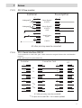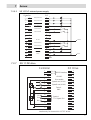
1
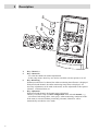
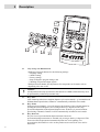
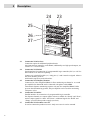
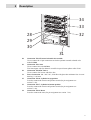
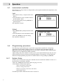
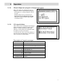
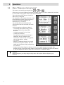
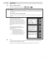
Operating Manual
Bedienungsanleitung
Universal-Steuergerät
Dual Channel Controller
97152
2
Contents
1
Please observe the following ..............................................................52
1.1
1.2
1.3
1.4
Emphasized sections.......................................................................................................52
Items supplied.................................................................................................................52
Safety instructions ..........................................................................................................52
Field of application (Intended Use)................................................................................53
2
Description..........................................................................................54
2.1
2.2
2.3
2.1.1
2.1.2
2.4
2.5
2.5.1
2.5.2
2.6
2.6.1
2.6.2
2.6.3
2.7
2.7.1
2.7.2
2.7.3
2.8
Theory of operation ........................................................................................................54
Displays, operating elements and connections...............................................................55
Start display - Overview.................................................................................................62
Display overview............................................................................................................62
Status numbers of program steps....................................................................................62
Controller access function ..............................................................................................63
Modes of operation.........................................................................................................63
Time controlled mode ....................................................................................................63
Continuous mode............................................................................................................63
Menu types .....................................................................................................................64
On / Off menus ...............................................................................................................64
Selection menus..............................................................................................................64
Value setup menus..........................................................................................................64
Peripheral connection options using valve modules ......................................................64
Integrated pneumatic solenoid valve module: 1 dispense channel.................................65
Integrated pneumatic solenoid valve module: 2 dispense channels
without advancing slide..................................................................................................65
External pneumatic/electric solenoid valve module: 2 dispense channels.....................66
Factory settings...............................................................................................................67
3
Technical Data ....................................................................................68
3.1
3.2
3.3
Electrics ..........................................................................................................................68
Pneumatics......................................................................................................................68
4
Installation...........................................................................................69
4.1
4.2
4.3
4.4
4.5
Environmental and operating conditions........................................................................69
Space requirements.........................................................................................................69
Connecting the unit ........................................................................................................69
Startup ............................................................................................................................69
Shutdown........................................................................................................................69
Dimensions and other data .............................................................................................68
49
Contents
50
5
Operation ............................................................................................ 70
5.1
5.2
5.2.1
5.2.2
5.2.3
5.2.4
5.2.5
5.2.6
5.3
5.3.1
5.3.2
5.3.3
5.3.4
5.3.5
5.4
5.5
5.6
5.7
5.7.1
5.7.2
5.8
5.8.1
5.8.2
5.9
5.10
5.11
5.11.1
5.11.2
5.11.3
Lock/unlock controller ................................................................................................... 70
Programming procedure................................................................................................. 70
System setup................................................................................................................... 70
Dispense channel configuration ..................................................................................... 71
Setup mode..................................................................................................................... 71
Timing setup................................................................................................................... 71
Further adjustments........................................................................................................ 71
Checking of setup........................................................................................................... 71
Menu "System setup" ..................................................................................................... 72
Language ........................................................................................................................ 72
Valves and channels:...................................................................................................... 72
Reset to factory settings: ................................................................................................ 72
Stored dispense program changeover types: .................................................................. 73
I/O signal status.............................................................................................................. 73
Menu "Dispense channel setup"..................................................................................... 74
Menu "Setup mode" ....................................................................................................... 75
Menu "Dispense, pre-delay and post-delay times, DC motor speed" ............................ 76
Menu "Online Flow Monitor" ........................................................................................ 77
Value setup..................................................................................................................... 77
Activation of reference dispensing................................................................................. 77
Setup of reservoir pressure, empty and refill signals ..................................................... 78
Reservoir pressure setup ................................................................................................ 78
Empty and refill signals ................................................................................................. 78
Menu "Preselection of stored dispense programs"......................................................... 78
Setup of dispense time ................................................................................................... 79
Programming of Online Flow Monitor .......................................................................... 81
Actuate flow monitoring ................................................................................................ 82
Setup of parameters for monitoring ............................................................................... 83
Setup of reference dispensing ........................................................................................ 84
6
Troubleshooting.................................................................................. 86
7
Annex.................................................................................................. 87
7.1
7.2
7.2.1
7.2.1.1
Spare parts and accessories ............................................................................................ 87
Pin assignment ............................................................................................................... 87
XS 1 Start ....................................................................................................................... 87
XS 1 Start via foot switch ............................................................................................. 87
Contents
7.2.2
7.2.2.1
7.2.2.2
7.2.3
7.2.4
7.2.5
7.2.6
7.2.6.1
7.2.6.2
7.2.7
7.2.8
7.2.9
7.2.10
7.3
XS 2 Product reservoir ...................................................................................................88
XS 2 product reservoir with digital level sensor (e.g. model 97125).............................88
XS 2 Analog product reservoir (e. g. models 97106/97108)..........................................88
XS 3 Flow monitor .........................................................................................................89
XS 5 Serial interface RS232...........................................................................................89
XS 8 I/O Port ..................................................................................................................90
XS 10 PLC......................................................................................................................90
XS 10 PLC internal power supply..................................................................................90
XS 10 PLC external power supply .................................................................................91
XS 11 DC drive ..............................................................................................................91
XS 12 External solenoid valve module ..........................................................................92
XS 16 Rotor unit.............................................................................................................92
XS 17 / XS 18 Proximity switch advancing slide ..........................................................92
EC Declaration of Conformity .......................................................................................93
51
1
Please observe the following
Before installing the system: For safe and successful operation of the unit, read these instructions
completely. If instructions are not observed, the manufacturer can assume no liability.
Be sure to keep the manual close at hand for further reference.
1.1
Emphasized sections
Danger!
Danger is the signal word used to indicate an imminently hazardous situation that, if not avoided,
will result in death or severe injury.
Caution!
Caution is the signal word used to indicate a potentially hazardous situation which, if not
avoided, could result in moderate or minor injury.
Note!
Gives recommendations for better handling of the unit during operation or setup as well as during
maintenance or service.
The numbers printed in bold in the text refer to the corresponding item numbers in the illustration
on pages 10 – 16
• The point emphasizes an instruction step.
–– The dash emphasizes a list.
On-screen displays are shown in italics.
Keyboard key names are shown in bold italics.
Instruction steps in the illustrations are
indicated with arrows.
1.2
Items supplied
– Dual Channel Controller 97152, Order no. 1275665
– Pneumatic hose, 2 m
– Power cord
– Operating Manual
Note!
As a result of technical development, the illustrations and descriptions in this operating manual
may deviate in detail from the actual unit delivered.
1.3
Safety instructions
Please refer to the relevant Technical Data Sheet for the Loctite® adhesive to be processed.
Download from www.equipment-loctite.com or request the Technical Data Sheet and the Safety
Data Sheet (acc. to EU Directive 91/155/EU). Contact:
Henkel AG & Co. KGaA
+49 89 92 68 11 67
for the English language version of data sheets;
089-92 68 11 22
for the German language version of data sheets.
INSTRUCTIONS given in these data sheets must be followed scrupulously at all times!
52
1
Please observe the following
While under warranty, the unit may be repaired by an authorized Henkel service representative
only.
Danger!
The manufacturer cannot be held responsible for damage or injury of any kind because of misuse
or improper application or because of failure to observe safety instructions or warnings.
It is the responsibility of the user to ensure that all devices actuated by the controller are
positioned in a safe manner.
Do not remove, by-pass or disable any safety device! This can result in damage to the unit and is
therefore prohibited!
Always wear goggles when working with compressed air!
Disconnect power supply before opening the housing!
Check the power cord and the unit before each use. Damage to the power cord or the housing can
result in contact with live electrical parts.
Replace a damaged power cord immediately.
1.4
Field of application (Intended Use)
The Dual Channel Controller 97152 is a versatile multi-functional controller for actuating 1 – 2
dispensing valves as well as appropriate peripheral equipment such as reservoir, advancing slides,
rotor sprays, on-line flow monitors, etc.
The processes and the data for all channels are displayed clearly and concisely. Settings can be
made intuitively via the keyboard and the user interface.
For easier adjustment of the on-line flow monitor, the measured values are graphically displayed.
The amount of product dispensed is controlled by the amount of pressure in the reservoir and the
length of time the dispensing valve remains open, unless a volumetric dispensing system is used.
The controller can be integrated into fully automated assembly line operations by means of the
integrated PLC interface. Therefore the primary controller is liberated from additional, timecritical tasks related to dispensing control and monitoring. It is possible to query data records via
a PC interface for documentation, maintenance or quality assurance.
The controller is equipped with an integrated pneumatic solenoid valve module. Connecting an
external module is also an option.
53
2
2.1
Description
Theory of operation
The Loctite® Dual Channel Controller 97152 utilizes the latest microprocessor technology to
create a user-friendly control system for workstations in manufacturing environments.
The controller is made up of a micro-controller core, a user interface keypad and graphic LCD
display.
A solenoid valve module and a precision pressure regulator are integrated into the unit; an
external solenoid valve module may be connected as an additional option.
Multipole interfaces allow easy connection to peripheral devices (valves, reservoirs, dispense and
flow monitors or PLC).
The keypad allows the user to easily change dispense time, pressure, and mode of operation
settings. All adjustments and the system status overview are displayed on the screen.
The program of controller 97153 provides various selection directories for controlling peripheral
units to implement a multi-functional dispensing system. For activation of the required peripheral
units, the relevant settings of system and channel menus are activated one after the other on the
digital display. Any peripheral unit that is not required must be deactivated (Off).
The system controls only the activated peripheral units, even if additional deactivated units are
installed. This allows different component combinations to be selected from among the
dispensing system components connected, as appropriate for the specific dispensing task.
Up to 4 different dispense applications with different dispense parameters can be set and stored.
These applications, as stored for a maximum of 4 different parts, can be actuated via the
keyboard or through the primary controller. No adjustments to product pressure in the reservoir
can then be made, or must be made manually.
For statistic process control, the data provided by the on-line flow monitor can be transmitted
from each channel via a standard serial interface.
Optional peripherals are:
– 1 DC servo motor (mainly for dispensing pumps),
– 1 external solenoid valve module 97204,
– up to 2 dispense valves
– up to 2 advancing slides with a pair of end position switches each
– up to 2 electric rotosprays,
– a product reservoir with low level and empty sensors,
– 2 external sensors for on-part detection of product,
– 2 preamplifiers for on-line flow monitoring.
For operation in line manufacturing or other automated workplace environments, the following
messages can be analyzed by a higher ranking controller:
– the Ready signal,
– the Refill and Empty signals from the product reservoir
– as well as all other Fault signals as a collective signal.
The individual steps of the automatic dispense cycle can be controlled via the MANUAL
OPERATION menu.
Caution!
All adjustment and setup operations in the PERIPHERALS main menu and in the MANUAL
OPERATION menu must be performed by trained and authorized personnel only!
54
2
2.2
Description
Displays, operating elements and connections
1
2
3
1
2
3
Display
Displays all information required for setup, status, etc., see section 2.3
Precision pressure regulator
Precision pressure regulator to regulate reservoir pressure.
Turn the regulator knob to adjust the dispense pressure within a range from 0.00 bar to
700 bar (0 to 100 PSI).
If error message “12 Supply? “ is displayed with a beep, the reservoir is either empty
or has been switched off.
If "-!-" is blinking and pressure is indicated with a beep, the dispense pressure setting
was changed by more than ± 10 %.
Press key 10 Enter to store the indicated dispense pressure as new comparison value
for automatic pressure monitoring. If no new dispense pressure is to be set, the old
dispense pressure setting must be restored. In both cases the error message and the
beep will disappear.
Selector / Confirm button
Turn the button to move from one menu option to the other or make settings such as
dispense time, start of flow monitoring, etc.
Push the button to confirm or store these settings.
It is recommended to press key 10 Enter to store the settings, as accidental turning of
the button may cause a change in the setting, so that the wrong value would be stored.
55
2
Description
4
5
7 6
97152
A
A
B
B
ESC
ESC
4
5
6
7
56
Start
Start
Key: Channel A
Key: Channel B
– To select the channel for further adjustments.
– In the setup menus, these keys are used to switch the relevant options on or off.
Key: Monitoring
Without preselection of a channel, the online monitoring On/Off menu is displayed.
With preselected channel, the online monitoring Setup menu is displayed. All
necessary adjustments can be made in the menu, such as adjustment of the required
tolerance, evaluation limits, etc.
Key: Adjustment
With preselected channel, the channel menu is displayed.
This key is used for setup of a basic configuration of the selected channel, e. g.
– activation of advancing slides, rotor sprays, online monitoring, continuous mode.
If the menu is activated without preselecting a channel, Channel A will be
automatically switched to active mode.
2
Description
97152
A
9
A
8
B
B
10
ESC
11
ESC
8
9
10
11
Start
Start
Key: Preselection of stored dispense programs
For manual selection of stored dispense applications. The display shows the selected
application in the 3rd line, indicated as letters (a-d) in square brackets.
Key: Time
With preselected channel, the value setup menu is displayed.
– For adjusting dispense, pre-delay and post-delay times.
If this key is pressed without preselecting a channel, Channel A will be automatically
switched to active mode.
Key: Enter
– For storing a setting.
– For resetting error messages. This function has priority when error messages are
displayed.
Key: ESC / Lock
– For leaving submenus without storing the values.
– For aborting input of values without storing.
– In the Operation display view, the system can be locked/unlocked by keeping the
key depressed for more than 2 s.
This prevents unauthorized access. A PIN must be entered for activation or
deactivation.
57
2
Description
97152
A
A
B
B
ESC
ESC
Start
Start
12 13
14 15
12
Key: Setup and Manual mode
Without preselected channel, for the following settings:
– Language setting,
– Channel setting,
– Factory settings,
– Setup of dispense program change, and
– Checking of input and output signals.
With preselected channel, the adjustments for setup mode can be made, such as
dispensing valve On or Off.
Caution!
All adjustment and setup operations in the MANUAL OPERATION directory must
be performed by authorized personnel only!
13
14
15
58
Key: Start
After channel preselection a complete dispense cycle can be started, e. g. in manual mode.
Without channel preselection, Channel A is automatically switched to active mode.
Key: Prime
With preselected channel, is used for priming the feed line of the selected channel or
opening the selected dispense valve as long as the key is depressed. This step
proceeds independent of the adjusted dispense time. If this key is pressed without
preselecting a channel, Channel A will be automatically switched to active mode.
Key: Reservoir
Key for reservoir pressurization/depressurization. Reservoir
pressurization/depressurization is actuated only as long as the key is depressed. The
reservoir will be depressurized automatically after low level signaling. For
pressurization, the hand lever valve on the product reservoir must be set to ON or
Pressurize.
2
Description
P in
6-8 bar
I/0
P in
6-8 bar
I
P out
0.1-7 ba
r
0
I
I
0
P out
0.1-7 ba
r
0
I/0
I
0
A
B
A
B
XS16
16
16
17, 18
19
20, 21
22
XS5 RS
232
17 18 19
20 21
22
Pneumatic Connection Reservoir
Regulated air pressure supply (0 - 7 bar, 0 – 100 PSI) to the reservoir, for
+ 0.05
air hose OD Ø 6 mm –0.10 , ID Ø 4 mm.
Pneumatic Connection A to a dispense valve
I = Dispense valve open.
O = Dispense valve closed.
Use port I for single actuated dispensing valve and close port 0 with plug, for air hose
+ 0.05
OD Ø 4 mm –0.10 , ID Ø 2.5 mm.
Main air connector 2 - 10 bar (30 PSI - 145 PSI) for
+ 0.05
air hose OD Ø 6 mm –0.10 , ID Ø 4 mm
Pneumatic Connection B to one dispense valve or one advancing slide
I = dispense valve open or advancing slide forward.
O = dispense valve closed or advancing slide backward.
Use port I for single actuated dispensing valve and close port 0 with plug, for air hose
0.05
OD Ø 4 mm +–0.10
, ID Ø 2.5 mm.
I/O switch
The power switch is used to switch the unit on and off.
59
2
Description
24
25
XS16
XS5 RS
XS3 Flow
26
27
232
Monitor
ervoir
26
27
60
XS17
XS10 PLC
Interface
XS12 Va
XS18
XS1 Sta
rt
Made in
25
Port
lves
Place for
24
XS8 I/O
XS2 Res
Henkel AG
Standort & Co. KGaA
M
Gutenber ünchen
gs
D-85748 tr. 3
Garching
23
23
XS11 DC
Drive
100-240
VAC, 50
/60 Hz
Fuse
Power Co : 2A T (time-lag
)
nsumption
: 100 W
Serial No
. Sticker
German
y
Connection XS 8 I/O Port
Connection option for additional peripheral units.
One input and one output for each channel, additionally two high-speed outputs, see
section 7.2.5 "XS 8 I/O Port".
Connection XS 5 RS232
Serial interface for connection of a programmable logic controller (PLC) or a PC for
data readout or for firmware updating.
Connect via 9 pin Sub D cable (1:1). Only pins 2, 3 and 5 must be assigned. Observe
the serial interface protocol.
9600 baud/1stop bit/no parity/8 data bits.
Connection XS 3 Dispense monitor
Connector for a Pre-Amplifier 97211, for flow monitoring on channel A. A second
pre-amplifier for channel B can be connected with splitter cable 97529.
Calorimetric dispense monitoring requires only one Pre-Amplifier 97512. Unlike
pressure based monitoring systems, this pre-amplifier can be used for monitoring
2 dispense valves.
Connection XS 10 PLC
Parallel interface for connection of a programmable logic controller.
Per dispense channel, two output signals each are available for “Ready” and “Error”,
and two input signals for “Start” and “Reset”; additional signals for “Refill” and
“Empty” provided from product supply (reservoir).
Connection XS 2 Product reservoir
Is used to connect the product reservoir. Only one reservoir can be actuated.
2
Description
XS16
XS5 RS
XS3 Flow
232
Monitor
XS8 I/O
34
Port
XS17
XS10 PL
C Interfa
ce
XS2 Res
ervoir
XS12 Va
lves
XS18
33
XS1 Star
t
28
29
30
Henkel AG
Standort & Co. KGaA
Münche
n
Gutenbe
rg
D-85748 str. 3
Garching
Place for
Se
XS11 DC
32
Drive
100-240
VAC, 50
/60 Hz
Fuse
Power Co : 2A T (time-lag
)
nsumption
: 100 W
rial No. St
icker
Made in
German
y
31
28
29
30
31
32
33
34
Connection XS 12 External solenoid valve module
Use to connect the 15 pin connection cord to the optional external solenoid valve
module 97204.
Connection XS 1 Start
Use to connect foot switch 97201.
Two Start inputs each for channels A and B via special start splitter cable 97203.
Connection XS 10 DC Drives
Use to connect a DC motor with drive box.
Power Connection 100 - 240 VAC, 50/60 Hz with glass tube miniature fuse 2A semi
time-lag, 5 x 20 mm
Connection XS 18: Cylinder in top position
Is used to connect the electric end position switch (for pin assignment see
section 7.2.10).
Connection XS 17: Cylinder in bottom position
Is used to connect the electric end position switch (for pin assignment see
section 7.2.10).
Connection XS 16: Rotor
Is used to connect the rotor (for pin assignment see section 7.2.9).
61
2
2.3
2.3.1
Description
Start display - Overview
Display overview
This display is an overview of the most important parameters of all active channels. The factory
default setting for Channel A is always in active mode. The display also shows the status of
product supply if a reservoir has been connected.
2 lines of information about the channels
(channel status) are displayed.
– The capital letter in the frame indicates the
dispense channel,
– Program step of the channel as a figure.
Used as reference for fault tracing in the
program sequence – see section 2.3.2,
– Status of the dispense channel as a memo
(plain text) for the most important program
steps, errors, etc.,
– Programmed dispense time in seconds.
Time runs down as dispense cycle proceeds. Time runs up in continuous mode.
The bottom line, from left to right, indicates
–reservoir fill level,
–product pressure in the reservoir,
–locked / unlocked status of controller,
–active dispense program (a-d), and
–the firmware version.
2.3.2
Status numbers of program steps
These program steps may also be used for error tracing and troubleshooting. In case of any
questions it is very helpful for Henkel Service engineers to have these numbers for reference.
Status Number
62
Description of Program Step
Display message
9
Check if start signal is gone
10
Wait for start signal
Ready
12
Product supply not OK
Supply?
14
Flush via the keyboard
Flush
20
Started, set times
32
Wait for advancing slide
42
Wait for signal "Rotor speed o. k."
44
During pre-delay time
Pre time
52
During dispense time
Dispensing
62
During post-delay time
Post time
64
Wait for rotor run down time
66
Wait for advancing slide in top position
70
Dispensing completed, peripheral OK
Mess.
92
Emergency stop wait for reset
STOP
98
Error: Wait for reset signal
2
2.4
Description
Controller access function
This function is a safety feature to safeguard the system against unauthorized manipulation.
Enter a PIN as desired to prevent unauthorized users from configuring the controller, changing
dispense applications, etc.
Enter number "2000" to unlock.
In locked condition, only the following functions can be accessed:
– On/off switching of product reservoir, i.e. reservoir pressurization/depressurization for
replacing the bottle of product..
– Start via foot switch, or by external actuation of a dispense cycle, not by
pressing key 13 Start.
– Resetting of error messages.
2.5
2.5.1
Modes of operation
Time controlled mode
Use this mode for internal timing of dispensing and delay times.
Times are adjusted by the user and remain unchanged for longer periods.
Benefits
– Very high precision of dispense timing is achieved.
– Maximum measuring accuracy for flow monitoring is available without constraints.
2.5.2
Continuous mode
Used when different dispense times are necessary, e. g. for different dispense amounts on the
parts, or for different parts.
Dispense times have to be provided by a higher ranking controller such as a plant PLC or a robot
controller.
Benefit
– High flexibility by synchronization with robot systems.
Limitations
– Fluctuations in PLC runtime directly affect both the dispense time and the runtime of the
connected advancing slides. Therefore, this mode is not recommended for options using
internally controlled advancing slides.
– Flow monitoring is available for time independent operation only.
63
2
2.6
Description
Menu types
Push the relevant keys to open a menu.
While the red ring on the Selector / Confirm button is illuminated, the button can be turned or
pressed to
– change settings such as dispense time,
– scroll within a menu, but also to
– store the selected value.
Within the On/Off menu, the channel keys for dispense channels A and B are defined as
switches.
Within the channel setup menu, the channel keys for dispense channels A and B are assigned as
scroll keys, as the button is required for setup of time values. Channel key A scrolls upward,
channel key B downward.
In case of a wrong input, abort the procedure by pushing key ESC/Lock and start again.
2.6.1
On / Off menus
This description applies to the following menus:
– "Dispense channel setup" with preselection of the dispense channel
– "Dispense channel setup" without preselection of the dispense channel
– "Online Flow Monitor" without preselection of the dispense channel (for reference dispensing
cycles)
– "Setup mode" with preselection of the dispense channel
2.6.2
Selection menus
This description applies to the following menus:
– "Preselection of stored dispense programs"
– "System setup"
2.6.3
Value setup menus
This description applies to the following menus:
– "Online Flow Monitor" with preselection of the dispense channel
– "Dispense, pre-delay and post-delay times, DC motor speed" with preselection of dispense
channels A or B.
– "Dispense, pre-delay and post-delay times, DC motor speed" without preselection of dispense
channels, channel A automatically selected
2.7
Peripheral connection options using valve modules
Various dispense valves and accessories can be connected to the controller. They all require a
pneumatic and/or electrical connection. For this purpose, pneumatic (internal valve module) and
electrical connections are provided on the rear panel of the unit. Whenever an external solenoid
valve module is used, all required dispense system components are connected to this module. It is
not possible to control components connected both to the internal and the external valve
module.
64
2
2.7.1
Description
Integrated pneumatic solenoid valve module: 1 dispense channel
All components are connected to the connectors of dispense channel A and actuated in the
dispense channel A system menu.
The Flow Monitor is connected to connection XS 3, the product reservoir is connected to
connection XS 2.
Connectable components
LOCTITE designations
1 dispense valve with double acting actuator
(for dispense valves with single acting
actuator, close port 0 with blind plug).
– Diaphragm Valve 97135 or 97136
– Stationary Applicator Valve 97113 or 97114
– Cyanoacrylate Dispense Valve 97134 or 98013
– Light Cure Dispense Valve 98009
– Advance Slide 97118 or 97119
– Rotospray 97115 or 97144
– Pressure based On-line Pre-amplifier
97211and dispense valve with pressure sensor,
or
– Calorimetric Pre-amplifier 97512 with
dispense valve 97830
– Eccentric Rotor Pumps 97660, 97663, 97665
or 97669
– 0.5 l product reservoir 97125 or 97106
– 2 l product reservoir 97108
– Supply Pump 97809
– 2 l Bag Dispenser 97124
1 double acting advancing slide
1 electric rotor unit
1 Dispense flow monitor
1 DC motor
1 Product reservoir
2.7.2
Integrated pneumatic solenoid valve module: 2 dispense
channels without advancing slide
All components are connected to the connectors of dispense channel A and actuated in the
dispense channel A system menu. In this configuration, the advancing slide connectors are used
for the 2nd dispense valve. Therefore, no advancing slide can be connected. The second dispense
valve with its flow monitor is actuated in the dispense channel B system menu. Flow monitors are
connected to connection XS 3, the product reservoir is connected to connection XS 2.
Connectable components
LOCTITE designations
2 dispense valves with double acting actuator
(for dispense valves with single acting
actuator, close port 0 with blind plug).
– Diaphragm Valve 97135 or 97136
– Stationary Applicator Valve 97113 or 97114
– Cyanoacrylate Dispense Valve 97134 or 98013
– Light Cure Dispense Valve 98009
– Rotospray 97115 or 97144
– Pressure based On-line Pre-amplifier
97211and dispense valve with pressure sensor
for each dispense channel (splitter cable 97529
required) , or
– Calorimetric Pre-amplifier 97512 with
dispense valve 97830
– Eccentric Rotor Pumps 97660, 97663, 97665
or 97669
– 0.5 l product reservoir 97125 or 97106
– 2 l product reservoir 97108
– Supply Pump 97809
– 2 l Bag Dispenser 97124
1 electric rotor unit
2 Flow monitors
1 DC motor
1 Product reservoir
65
2
2.7.3
Description
External pneumatic/electric solenoid valve module: 2 dispense
channels
All components must be connected to the external solenoid valve module. Connecting
components to a mixed configuration of internal and external valve modules is not possible.
Flow monitors are connected to connection XS 3. Use splitter cable 97529 for connecting two
pressure based on-line preamplifiers.
The product reservoir is connected to connection XS 2.
Dispense channels A/B, each
Connectable components
LOCTITE designations
1 dispense valve with double acting actuator
(for dispense valves with single acting
actuator, close port 0 with blind plug).
– Diaphragm Valve 97135 or 97136
– Stationary Applicator Valve 97113 or 97114
– Cyanoacrylate Dispense Valve 97134 or 98013
– Light Cure Dispense Valve 98009
– Advance Slide 97118 or 97119
– Rotospray 97115 or 97144
– Pressure based On-line Pre-amplifier
97211and dispense valve with pressure sensor,
or
– Calorimetric Pre-amplifier 97512 with
dispense valve 97830
– Eccentric Rotor Pumps 97660, 97663, 97665
or 97669
1 double acting advancing slide
1 electric rotor unit
1 Flow monitor
1 DC motor
For both dispense channels
Connectable components
1 Product reservoir
LOCTITE designations
– 0.5 l product reservoir 97125 or 97106
– 2 l product reservoir 97108
– Supply Pump 97809
– 2 l Bag Dispenser 97124
Both dispense valves must be supplied from one product reservoir as the controller will handle
only one reservoir low level sensing function. Whenever supplying a second dispense valve from
the reservoir, replace the reservoir lid with a lid with 4-way splitter 8953094 for the 0.5 l
reservoir. Use 4-way splitter 8953095 for the 2l reservoir.
66
2
2.8
Description
Factory settings
Factory settings for both dispense channels
Advancing slide........................................................................... Off
Rotor............................................................................................ Off
Flow monitor ............................................................................... Off
DC motor..................................................................................... Off
Continuous mode......................................................................... Off
Common start .............................................................................. Off
Dispense time .............................................................................. 0.20 s
Pre-delay time.............................................................................. 0 s
Post-delay time ............................................................................ 0 s
Flow monitor ............................................................................... Off
Tolerance ..................................................................................... 50%
Dispense measurement start point ............................................... 20
Dispense measurement stop point ............................................... 100
Measurement factor ..................................................................... 1
Flow monitor reference measurement ......................................... Off
Additional factory settings for dispense channel A
DC motor speed........................................................................... 10%
System setup
Controller unlocked .....................................................................
Language .....................................................................................
Valve module configuration ........................................................
Changeover stored dispense programs ........................................
Yes
English
2 channel internal V
Off
Additional factory settings
Reservoir pressure when unit is switched on............................... On (cannot be changed)
Stored reference reservoir pressure ............................................. 0 bar
67
3
3.1
3.2
3.3
68
Technical Data
Electrics
Power supply
100-240 VAC; 50/60 Hz
Power consumption
approx. 60 W
Power fuse
Glass tube miniature fuse, 2A semi time-lag
Internal control voltages
5 VDC; 24 VDC
Protection
IP 33 acc. to VDE 0470, Part 1 / EN 60529-1991
Pneumatics
Pneumatic supply
min. 2 bar; max. 10 bar
Observe technical data specified for the dispense
valve!
Quality
If the required quality is not achieved,
install a Loctite® 97120 filter regulator.
filtered 10 µm, oil-free, non-condensing
Adjustment range of the pressure
regulator
0.1 – 7.00 bar
Pressure indication
0.1 – 7.00 bar
Pressure range of optional external
solenoid valve module 97204
2.5 – 8 bar
Pneumatic hose size, P in
ID Ø 4 mm ; OD Ø 6 mm
Pneumatic hose size, to connect reservoir
ID Ø 4 mm; OD Ø 6 mm –0.10
OD Ø ¼ inch (6.3 mm) not suitable!
Pneumatic hose size, to connect dispense
valves
ID Ø 2.5 mm ; OD Ø 4 mm
Pneumatic hose size, to connect
advancing slides
ID Ø 2.5mm; OD Ø 4 mm
Order No. 88649
+ 0.05
–0.10
+ 0.05
Dimensions and other data
Dimensions W x H x D:
150 x 230 x 270 mm
Operating temperature
+10 °C to +40 °C
Storage temperature
-10 °C to +60 °C
Weight
3.0 kg
+ 0.05
–0.10
+ 0.05
–0.10
4
4.1
Installation
Environmental and operating conditions
– Keep product feed lines as short as possible. The shorter the feed line, the smaller the specific
resistance and the lower the required dispense pressure.
– Avoid kinking of feed lines.
– Typically, the feed line should be no longer than 2 m.
– Carefully tighten all fittings.
– Avoid exposure to direct sunlight and UV radiation!
– Avoid condensing humidity.
– Avoid splash water.
– For indoor use only. Not intended for use in potentially explosive areas.
4.2
Space requirements
97152
A
B
230 mm
9"
Freiraum für
Kabel und
Schläuche
ESC
Start
Area to be left
clear for cables
and tubes
~100 mm
~4"
4.3
270 mm
10.7"
~150 mm
~5.7 "
Connecting the unit
• Connect power cord to the power supply.
• Connect pneumatic hose to compressed air supply 19.
4.4
Startup
• Switch the power switch 22 to position I.
4.5
Shutdown
• Switch the power switch 22 to position O.
• Disconnect power cord from line voltage.
• Switch off external pneumatic supply.
69
5
5.1
Operation
Lock/unlock controller
This function is a safety feature to safeguard the system against unauthorized manipulation, refer
also to section 2.4.
Lock
• Keep ESC/Lock key 11 depressed for more
than 3 s.
• Turn the button to select a number which is
not the number "2000".
• To store the setting, press key 10 Enter or
push the button.
The controller is locked.
Unlock
• Keep ESC/Lock key 11 depressed for more
than 3 s.
• Turn the button to select the number "2000".
• Press key 10 Enter to store the setting.
The controller is unlocked.
5.2
Programming procedure
The following steps describing how to proceed to program the controller for a dispensing
application are provided for guidance. However, you should clarify beforehand what the
application looks like and what peripherals are to be used or connected. Please contact Henkel
Technical Service in Munich for further assistance.
Adjust settings only where needed. To allow you to execute the individual steps, they are crossreferenced to the relevant sections in the Operating Manual. The sequence of steps should be
followed. Each programming step must be confirmed and saved by pushing key 10 Enter.
5.2.1
System Setup
To allow you to execute these steps, the controller must be in unlocked condition. Section 5.1.2
describes how to unlock the controller.
• Press key 7 Setup and select menu option Language selection,
• Turn button to scroll to menu option
– Valves and channels, next select
– Factory settings, next select
– Dispense program preselection, next select
– Input/Output status.
For further procedure within the menu refer to section 5.3
70
5
5.2.2
Operation
Dispense channel configuration
The key for Channel A is quoted only as an example. Push the key of the channel for which you
have to make the adjustments.
• First press key 4 Channel A, then key 7 Setup.
–For adjustments in menu option Advancing Slide,
proceed as described in section 5.4
–For adjustments in menu option Rotospray,
proceed as described in section 5.4
–For adjustments in menu option Flow monitor,
proceed as described in sections 5.4 and 5.7.
–For adjustments in menu option DC motor,
proceed as described in sections 5.4 and 5.6.
–For adjustments in menu option Continuous mode (externally actuated dispense time),
proceed as described in section 5.4
–For adjustments in menu option Common start,
proceed as described in section 5.4
5.2.3
Setup mode
• First press key 4 Channel A, then key 7 Manual mode,
for further procedure see section 5.5.
5.2.4
Timing setup
• First press key 4 Channel A, then key 9 Time.
–Set the dispense time,
–Set predelay and postdelay times only if you require them,
e. g. when operating an advancing slide or a rotor unit.
–Percentage speed of a connected DC motor,
for further procedure see section 5.6
5.2.5
Further adjustments
• Adjust dispense pressure for connected product reservoir.
The amount of product dispensed is determined by several factors including the following:
– Amount of pressure in the reservoir
– Length of time the dispensing valve remains open.
Required information is described in section 5.8.
5.2.6
Checking of setup
• First press key 4 Channel A, or key 5 Channel B, then key 13 Start to start a dispense cycle.
Caution!
If a reservoir pressure has been set for the product supply unit, product will flow from the
connected dispense valves!
Furthermore, the advancing slides connected to the system will move to dispensing position.
Be sure to take appropriate safeguarding action!
• Actuate a connected foot switch to trigger a dispense cycle start and check if adjustments are
correct.
• If a primary controller (PLC) is connected, trigger a dispense cycle start to check setup and
signal exchange.
71
5
5.3
Operation
Menu "System setup"
The first step is to preconfigure the controller. For this purpose, the controller must be unlocked.
This menu is activated by pressing the key
This is the menu for general setup of the
dispensing system.
Turn the button to select the desired entry
which will be displayed in large letters, and
confirm by pressing key 10 Enter.
Confirm any adjustments to settings by
pressing key 10 Enter.
Press key 11 ESC/Lock to leave the menu.
5.3.1
Language
Currently only English and German available.
5.3.2
Valves and channels:
This is the option for selecting the dispense
channels and valve modules to be used.
– 1 dispense channel (A), using the integrated
valve module.
– 2 dispense channels (A and B), using the
integrated valve module.
– 2 dispense channels (A / B), using the
external solenoid valve module 97204.
5.3.3
Reset to factory settings:
Press key 10 Enter to reset all setup
adjustments to the factory setting.
Programmed values and functions will be
deleted.
Press key 11 ESC/Lock to leave the menu
without deleting these values/functions.
72
.
5
5.3.4
Operation
Stored dispense program changeover types:
This is the option for selecting the type of
changeover for the stored dispense programs.
– No changeover, as these programs will not
be used.
– Manual changeover by pressing key 8
Preselection of stored dispense programs
– Changeover using external control signal
via interface XS 8.
5.3.5
I/O signal status
This is an overview of all digital and analogue
inputs and outputs with their current switch
statuses. To allow checking of individual
functions, switch statuses are displayed either
in capital or in lower-case letters.
As a general rule, lower case letters indicate a
non-active/non-switched status; capital letters
refer to an active/switched status.
Description of signal messages
st
Start XS 1
sp
Start PLC interface
fr
Limit switch, dispensing position (forward)
ba
Limit switch, home position (back)
ro
Rotor Speed o. k.
re
Reset input PLC
in
XS 8 I/O input
An:XXXX
I:XXXXXXXX)
Online inputs
Power
73
5
5.4
Operation
Menu "Dispense channel setup"
This menu is activated by pressing the keys A or B and
.
If the menu is activated without preselecting a channel, Channel A will be automatically switched
to active mode. Setup options are the same for both channels.
This is the menu where dispense channels A
and B can be configured.
The channel keys for dispense channels A and
B are defined as switches. The relevant keys
are used to switch the peripherals and
functions On () or Off (X).
Any unit that has been connected to the
system but has not been activated will not be
actuated.
Activation options per dispense channel:
– 1 advancing slide (double acting), with 2
proximity switches for end position
detection.
– 1 electric rotor unit 97115 or 97144
– 1 Online Flow Monitor.
For applications requiring monitoring of
Channel B, the flow monitor can be
connected to connector XS 3 using splitter
cable 97529/order no. 945063.
– 1 DC motor
– Function “Continuous Mode“ for external
actuation of a dispense channel. The start
signal must be present as long as dispensing
is to continue.
– Common start of both dispense channels with one start signal (internal or external). This
function can only be activated in the channel system menu for channel B; the menu for channel
A will only display the function. May also be activated as “Continuous Mode“.
Caution!
Different dispense, pre-delay and post-delay times will result in different dispense cycle
durations.
74
5
5.5
Operation
Menu "Setup mode"
This menu is activated by pressing the keys A or B
and
.
Caution!
In this mode, all units connected to the controller or to the external valve module will be actuated.
For example, a connected advancing slide will move to its dispense position when the channel is
switched on ().
There must be no obstacles within this range.
Any unit switched on in this mode, although not activated in the channel system menu, will be
actuated.
This On/Off menu is provided for setup
operation of a dispense system.
In this menu, the manual mode for dispense
channels A or Be can be switched on or off.
The channel keys for dispense channels A and
B are defined as switches. The relevant key is
used to switch the connected unit On () or
Off (X).
The three little bars in the display are
provided for advancing slide and rotor unit
status indication.
They have the following meaning:
– < – advancing slide in home position,
corresponding limit switch active.
– – > advancing slide in dispensing position,
corresponding limit switch active.
R – – Rotor unit has reached preset speed.
Note!
As long as the setup mode has been activated for any one dispense channel, no dispensing cycle
can be started in the other dispense channel.
Malfunctions occurring during normal dispensing operating are ignored in manual mode.
75
5
5.6
Operation
Menu "Dispense, pre-delay and post-delay times, DC motor
speed"
This menu is activated by pressing the keys A or B
This is the option for selecting
– Dispense time,
– Pre-delay time,
– Postdelay time and
– Percentage speed of a connected DC motor
Use keys 4 Channel A or
5 Channel B to scroll through the menu.
Adjustments are made by turning the button.
Pre-delay time:
This is the time that elapses until the rotor or
the dispense step starts.
Post-delay time:
This is the time after end of the dispense step.
Before the next step, e.g. before the
advancing slide returns to home position, the
rotor continues to rotate for a short time to
spin off any residual product remaining on the
slinger disc. When this time has elapsed, the
controller is "Ready", and a new start signal
can be actuated.
DC motor:
This is the option for selecting the percentage
speed of a connected DC drive.
100 % is the maximum motor speed. For
Rotor Pumps 97660, 97663, 97665 and
97669, the ideal speed range is between 30
and 60 %. When priming the pumps, the
speed may be temporarily reduced to a
minimum of 10%. For further information
please refer to the operating manual of the
relevant dispensing pumps.
76
and
.
5
5.7
5.7.1
Operation
Menu "Online Flow Monitor"
Value setup
This menu is activated by pressing the keys A or B and
.
Pressing the key 6 Monitoring without preselecting a channel will automatically switch Channel
A to active mode. Preselection of the dispense channel is required to call up the setup menu for
Channel B.
This is the option for selecting
– tolerance, 10% - 400%,
– evaluation start point,
– evaluation stop point, and
– measuring time factor value, 1- 10.
Use keys 4 Channel A or
5 Channel B to scroll through the menu.
Adjustments are made by turning the button.
For further information see section 5.11.
5.7.2
Activation of reference dispensing
This menu is activated by pressing the key
.
In this menu, the reference measurement of
the Online Flow Monitor for dispense
channels A or B can be switched on or off. As
a first step, monitoring of the dispense
channel must be activated as described in
section 5.11.1. The display changes from OFF
to X. The channel keys for dispense channels
A and B are defined as switches. The relevant
key is used to switch the flow monitor
On () or Off (X).
77
5
5.8
5.8.1
Operation
Setup of reservoir pressure, empty and refill signals
Reservoir pressure setup
• Turn the regulator knob 2 to adjust the dispense pressure within a range from 0.00 bar to
7.00 bar (0 to 100 PSI).
If error message “12 Supply?“ is displayed with a beep, the dispense pressure setting was
changed by more than ± 10 %.
Press key 10 Enter to store the indicated dispense pressure as new comparison value for
automatic pressure monitoring. If no new dispense pressure is to be set, the old dispense pressure
setting must be restored. In both cases the error message and the beep will disappear.
5.8.2
Empty and refill signals
Product bottle in the reservoir is full.
Product bottle in the reservoir is almost empty. When this signal is displayed,
available product is sufficient for further dispensing shots. However, it would be
wise to get a new, full product bottle ready.
The product bottle is empty.
No further dispensing shots are possible as this signal prevents triggering of any
new dispense cycles.
This symbol in the display means that the reservoir is depressurized. The
reservoir can be opened to replace the product bottle.
The empty product bottle has been replaced by a full bottle, and the product
reservoir lid is clamped in place. The reservoir must be reactivated by pressing
the blinking key 15 Reservoir. Then, pressurize the reservoir to the pre-set
pressure and trigger the next dispense cycle.
The monitoring display indicates only error message “12 Supply ?“ with a beep. To check if the
reservoir is empty, press key 11 ESC/Lock to go to the System Display.
5.9
Menu "Preselection of stored dispense programs"
This menu is activated by pressing the key
.
This menu is used for manual selection of
stored dispense programs, to execute and, if
necessary, change programs.
4 different dispense programs can be stored.
To store a dispense program, the relevant
parameter set must first be selected.
• Select the parameter set by turning the
button, store by pressing key 10 Enter.
Menus "Dispense, pre-delay and post-delay times, DC motor speed" and "Online Flow Monitor"
can now be accessed for setup. Whenever these settings are stored, the controller will assign them
to the selected parameter set. The reference measurement of the Online Flow Monitor will also be
transferred. Configuration settings made in the "System setup" and "Dispense channel setup"
menus will not be stored in the parameter set.
To allow you to use this function, selection of the parameter sets must be defined in the "System
setup" menu - see section 5.3.
78
5
5.10
Operation
Setup of dispense time
This menu is activated by pressing the keys A or B
and
.
• Turn the button to select the desired dispense time and press key 10 Enter to store.
This section explains the necessary steps for adjusting the required amount of product to be
dispensed. It contains all the information required for easy and fast setup. In addition, the "Start
settings" table is explained.
The operating manuals of the relevant system components must be available for reference.
Dispense amount
The amount of product dispensed is determined by the following factors:
– Amount of pressure in the reservoir
– Length of time the dispensing valve remains open.
– Valve stroke
– Dispense needle
Drop size
Definition:
A small drop has a diameter of approx. 1 mm.
A medium-sized drop has a diameter of approx. 2.5 mm.
A big drop has a diameter of approx. 5 mm.
Dispense needles
Various dispense needle types and sizes are available for each product and corresponding
application of the dispense valve:
– Conical dispense needles made of polyethylene for high viscosity products and large dispensed
amounts.
– Stainless steel needles for low viscosity and UV curing products (especially suitable for spot
applications).
– Flexible dispense needles made of polyethylene
– PTFE-lined stainless steel needles (especially for fast curing products).
Dispense pressure
When dispensing Cyanoacrylate adhesives, the dispense pressure normally should not exceed
1 bar. If this pressure is not sufficient it would be better to increase the dispense time and/or use a
bigger dispense needle. The dispense time should be long enough to allow the dispense valve to
open and close properly.
79
-
5
Operation
Outgassing of products
To avoid problems due to outgassing of products, use low dispense pressure and longer dispense
timing for your process whenever possible. In addition, it is helpful to depressurize the dispense
valve at regular intervals.
If possible, reduce the valve closing speed (refer to operating manual of relevant dispense valve).
High viscosity products
Use a feed line with larger internal diameter for dispensing high viscosity products. Instead of
using a ¼“ feed line, use a ⅜“ feed line. Feed line Kit No. 97220, order no. 135561, is available
for this purpose.
Use a larger, conical dispense needle, e.g. needle PPC18GA, ID - ø 0.84 mm, green (No. 97222)
or PPC16GA, ID ø 1.19 mm, gray (No. 97221), otherwise the amount of product dispensed will
be insufficient.
Separation of products
To ensure optimum adhesive strength, the product should not be allowed to separate. Use only
small containers holding the amount of product consumed during a shift or a day to minimize
separation.
Avoid angled fittings for product connections, e.g. to the dispense valve. Use straight fittings
only. Care should be taken to run the feed line properly, with a wide radius.
Thixotropic products
Prolonged idle periods will change the flow behavior of a thixotropic product due to its chemical
properties. As a result, the amount of product dispensed will be reduced. To compensate for this
phenomenon, run 2 – 3 dispense cycles before returning the system to operation.
Start settings
Small drops
Dispense
time
in seconds
Low viscosity products up to
125 mPas (like fruit juice)
Cyanoacrylates and
anaerobics,
e.g. 401, 406, 496, 290
Medium viscosity products
up to 1,000 mPas (like heavy
oil), Cyanoacrylates and
anaerobics,
e.g. 243, 270, 480, 648
High viscosity products up to
10,000 mPas (like honey)
Cyanoacrylates and
anaerobics,
e.g. 326, 330, 572, 573, 574,
638
Paste and gel-type products
Cyanoacrylates, anaerobics
and silicones,
e.g. 454, 510, 660, 5088.
80
Medium-sized drops
Dispense
pressure
in bar
Dispense
time
in seconds
Dispense
pressure
in bar
Big drops
Dispense
time
in seconds
Dispense
pressure
in bar
0.5
0.2 – 0.6
0.5
0.5 – 1.0
1.0
0.5 – 1.0
0.5
0.5 – 1.0
1.0
0.5 – 1.0
1.0
1.0 – 2.0
0.5
0.7 – 1.2
1.0
1.0 – 2.0
2.0
1.0 – 2.0
0.5
1.2 – 2.0
1.0
1.7 – 2.5
2.0
2.0 – 3.0
5
5.11
Operation
Programming of Online Flow Monitor
The integrated flow monitoring function of controller 97152 is used for monitoring the quality of
adhesive applied to the parts. This means that the flow monitor detects and evaluates the
following dispensing malfunctions:
– Air bubbles in the dispensing system
– Pressure changes in the dispensing system
– Lost or clogged dispense needle
– Touch-down of dispense needle on the part.
The pressure based flow monitor measures the dispense pressure profile via a sensor and saves
this value. As a rule, the sensor is integrated in the dispense valve. The duration of measurement
corresponds to the duration of dispensing. In time controlled mode, the controller compares the
pressure profile that has been measured to a previously stored reference measurement, based on
3 different factors:
– Integral of pressure profile (equals the amount of product dispensed)
– Length of envelope curve for the pressure profile
– Maximum dispensing value (measured curve) to detect pressure peaks.
In continuous mode, only the pressure level during the dispensing step is compared to the
reference limit.
The calorimetric system is similar with respect to system integration and signal processing but is
based on a different measuring method. A miniaturized heating element placed in the product
flow gets slightly heated, and the temperature difference in the flowing product is analyzed. This
system is recommended in particular for flow monitoring of miniature dispensed amounts and
low pressure settings, irrespective of delivery pressure, product viscosity and dispense needle
diameter. The signal strength delivered by the pressure based method is too low for such
applications and cannot be reliably processed.
As long as the measured values are within a pre-defined tolerance range, the dispense cycle is
found to be OK, and the "Ready" signal is delivered to the controller. If the deviation is outside
the tolerance range, this dispense cycle is recognized and signaled as an error. It will also be
supplied as a fault signal to connector XS 10. The fault signal must be reset.
The system measures the previous dispense cycle and compares it to a reference measurement
which was stored previously and found to be OK. Tolerance can be fine adjusted within the range
from 10 to 400 % to determine the optimum between a false alarm and a reliable error
recognition. By setting a tolerance value the user specifies the degree of accuracy to be
maintained between any one measurement and the reference value. Air bubbles, clogged needles
or a needle touchdown may have a very strong effect on the envelope curve length. Therefore this
is generally the governing parameter for dispense monitoring.
All dispense curves are displayed in a window with x=120 pts. (points).
In time controlled mode, complete measurement curves are recorded automatically and
independent of the length of dispense time. If the time of measurement is to be significantly
longer than the time of dispensing, e.g. for visual inspection, the measuring time can be extended
by an adjustable factor (1-10).
In continuous mode, the complete dispensing step is measured and analyzed, but it is possible
that the measurement curve is not displayed completely. Only the first 1.2 s to 12 s after the start
of measurement are displayed. The length of measurement curve indication is dependent on the
selected factor. As the length of dispensing is not fixed in continuous mode, it may be impossible
to display the complete measurement curve if dispense processes are very long.
If several reference measurements are recorded in succession while the system is in time
controlled mode, the controller averages 8 measurements to get optimum reference values. For
this purpose, the tolerances for each reading are adjusted automatically for optimum results. This
is why 8 reference measurements should always be recorded.
Exception: Only one reference measurement can be made when the system is in continuous
mode.
81
5
5.11.1
Operation
Actuate flow monitoring
• Push the key for the channel for which the monitoring function is to be activated.
Screens displayed are different for each operating mode.
Screen display in time-controlled mode
Measurement curve
Boundary line
Measurement
Start of Evaluation
Boundary line
Measurement
End of Evaluation
X-Axis Dispense,
Lenght 120 pts.
Status line
– Status line – see section 2.6.2.
– X-axis dispense, length 120 pts (0- 119 pts) – the two boundary lines can be shifted within this
range, see section 5.8.2.
– Boundary lines for start and end of measurement
Screen display in continuous mode
Measurement curve
Boundary line
Measurement
Start of Evaluation
X-Axis Dispense,
Lenght 120 pts.
Status line
– Displayed range within which a measurement is OK. Range is determined by the controller and
displayed graphically, taking into account the preselected tolerance as well as the measured
reference.
82
5
5.11.2
Operation
Setup of parameters for monitoring
• Push the key for the channel for which the monitoring function has been activated.
• Push key 6 Monitoring to go to the setup menu.
If no graph is indicated, this means that no dispense monitoring function has been activated for
this channel. To activate the monitoring function, see section 5.8.1.
Setup of tolerance value
• Turn the button to select the desired
tolerance value
Adjustable range: 10-400 %
Setup of evaluation limits
Measurements will be evaluated within these
limits. The start point should be set to make
sure that measurement will not begin before
the dispense pressure is stable. The end points
can be adjusted to a setting which ensures that
any fluctuations at the end of the dispensing
process will be disregarded for the evaluation.
0 pt
120 pt
To increase the value, move the boundary line to the right, and vice versa. This applies for both
boundary lines.
To ensure optimum positioning of lines, a measurement should have been taken before making
this adjustment.
Start point (boundary line left)
Start of evaluation
• Press key 4 Channel A.
Adjustable range: 0-90 pts.
Stop point (boundary line right)
End of evaluation
• Press key 4 Channel A, or key 5 Channel B.
Adjustable range: 30-119 pts.
83
5
Operation
Setup of measuring time factor
• Press key 4 Channel A, or key 5 Channel B.
Adjustable factor: 1-10.
• For adjustments of values see section 5.1.
• Press key 10 Enter to store the settings and
return to the Monitoring screen
5.11.3
Setup of reference dispensing
• Press key 6 Monitoring. The overview of
flow monitoring modules is displayed.
• To run one or several reference dispensing cycles, monitoring of the dispense channel must first
be activated as described in section 5.11.1.
The display changes from OFF to X.
The channel keys for dispense channels A and B are defined as switches. The relevant key is
used to switch the flow monitor On () or Off (X).
• Press key 13 Start to run the reference
dispensing cycles for the active dispense
channel. A counter runs.
A maximum of 8 reference dispensing cycles
should be performed. Time intervals between
reference dispensing cycles should be equal to
the production line cycle times. A start signal
must be triggered for each reference dispense
cycle. Whenever another start signal is
triggered after the final reference dispense
cycle, the controller switches automatically to X. The number of dispense cycles triggered is
indicated as a numeral in square brackets. [8].
• Press key 10 Enter to store. Then return to the system display.
84
5
Operation
Monitoring status screen
This overview shows the current status of
connected flow monitors.
• Without channel preselection, press key 6
Monitoring twice.
Status displayed in time controlled dispense
mode:
I:00000 +00000 -00000
D:00000 +00000 -00000
P:0000 +0000
-0000
T:00000 +00000 -00000
Status displayed in continuous dispense
mode:
+:0000 Err: 000
-:0000 Err: 000
Description of status options in the display
In timed mode
I
Integral value
D
Curve length
P
Peak value
T
Time
+
–during reference measurements:
–during measurements:
maximum measured
upper limit including tolerance (above = error)
-
–during reference measurements:
–during measurements:
minimum measured
upper limit (below = error)
Current measured values
In continuous mode
+
–while referencing:
–while measuring:
maximum measured value
upper limit
-
–while referencing:
–while measuring:
minimum measured value
lower limit
Err
Number of times values were above or below the limits (if tolerance value setting is
exceeded ¨ error)
85
0
6
Troubleshooting
Malfunction
Digital display does not light
up.
Possible Cause
– No power supply.
– Power switch 22 in position O (Off).
– Power fuse 31 defective.
– Power cord defective.
– Controller defective.
Corrective Action
• Check supply voltage.
• Set power switch 22 to position I
(On).
• Check/replace 31 mains fuse.
• Replace power cord.
• Henkel Service.
– No compressed air.
– Product reservoir not actuated or
defective.
• Check compressed air supply.
• Check product reservoir (refer to
operating manual of the reservoir).
– Controller defective.
• Henkel Service.
Required pressure is not
reached.
– Supply pressure insufficient.
• Increase supply pressure. It must be
at least 0.5 bar above the desired
dispense pressure.
No, too little or too much
product.
Probably with fault signal
(with beep).
– Dispense pressure not correct.
– Pneumatic hose not correctly connected.
– Dispense needle clogged or too
small/big
• Correct the dispense pressure.
– Dispense valve not correctly connected
or defective.
• Check dispense valve (refer to
operating manual of the dispensing
valve).
• Check product reservoir (refer to
operating manual of the reservoir).
• Henkel Service.
No change in value on digital
display.
– Product reservoir manually
depressurized or defective.
– Controller defective.
• Correct pneumatic hose connection.
• Replace dispense needle.
LED in key does not light up.
– LED defective.
– Key defective.
• Henkel Service.
• If the key works (check via digital
display), emergency operation may
be continued until Henkel Service is
available.
No start signal.
– Automatic reservoir empty.
The Empty fault signal (with beep)
blinks on the digital display.
• Refill automatic reservoir.
– Plug in socket XS1: Start 29 loose.
• Set power switch 22 to position O
(Off). Tighten down plug. Set power
switch 22 to position I (ON).
– Foot switch defective.
• Replace foot switch.
– Internal control voltage not looped out
• Install jumper between pin 5 and
pin 8 of XS 1.
86
7
7.1
Annex
Spare parts and accessories
Item no. Description
Type no.
–
I/O Multiplex Box XS 8........................................................... 97522
7.2
Order no.
840911
–
I/O Multiplex Box XS 12......................................................... 97521
840910
–
Splitter cable XS 3/XS 4 .......................................................... 97529
945063
–
Start splitter cable..................................................................... 97203
142638
–
Foot switch............................................................................... 97201
88653
–
Filter regulator unit .................................................................. 97120
88649
–
Valve module .......................................................................... 97204
142639
Pin assignment
7.2.1
XS 1 Start
7.2.1.1
XS 1 Start via foot switch
Controller
1
2
Foot switch
Start A
Start B
1
2
3
3
4
4
2
2
S1
5
0 VDC
5
1
6
6
7
7
8
9
Pot. 0 VDC
+24 VDC
S2
1
8
9
87
7
Annex
7.2.2
XS 2 Product reservoir
7.2.2.1
XS 2 product reservoir with digital level sensor
(e.g. model 97125)
Reservoir
digital Levelsensor
Controller
4
1
Tank Refill
1
1
blue
2
4
0VDC/GND
3
1
Tank Empty
2
2
3
3
black
2
3
brown
+ 24V
0VDC
GND
GND
4
5
5
6
6
7
7
8
8
9
9
0VDC
4
1
2
3
Identification
Signal
+ 24V
Output
7.2.2.2
4
+ 24V
XS 2 Analog product reservoir (e. g. models 97106/97108)
Reservoir
analogue Levelsensor
Controller
4
1
Tank Refill
1
1
1
2
Tank Empty
2
2
1
2
3
3
4
4
5
5
2
4
3
1
2
3
0VDC
GND
GND
GND
2
3
88
6
7
7
8
8
9
9
max. 1.8 W
4
1
+ 24V
Output
6
Identification
Signal
+ 24VDC
Tankventil
7
7.2.3
Annex
XS 3 Flow monitor
Controller
Pre-Amplifier
1
Analogue/IN
2
3
Analogue/IN
4
5
1
Sensor Signal A
0-10VDC
2
Sensor Signal B
0-10VDC
GND
4
3
5
6
7
6
Identification
Signal
7
8
8
9
9
+ 24VDC
All other pins may never be connected!
7.2.4
XS 5 Serial interface RS232
To be connected via serial cable, pins 7 and 8 must not be assigned. Observe the serial interface
protocol.
9600 baud/1stop bit/no parity/8 data bits.
Controller
Connection Cord
1
2
3
Rx
Tx
4
5
Gnd
6
7
8
9
*Tx
*Rx
PC
1
1
1
2
2
2
3
3
3
4
4
4
5
5
5
6
6
6
7
7
7
8
8
8
9
9
9
All other pins may never be connected!
* The pins can be used ONLY for firmware updates!
89
7
7.2.5
Annex
XS 8 I/O Port
Controller
1
2
3
4
5
6
I/O Output A
I/O Output B
Hi-Speed Output A
Hi-Speed Output B
I/O Inputg A
I/O Input B
GND Output
11
12
12
13
13
GND Input
+24 VDC
XS 10 PLC internal power supply
Controller
6
9
10
11
15
Ready Channel A
Ready Channel B
Error Channel A
Error Channel B
Start Channel A
Start Channel B
1
2
3
4
5
1
6
1
2
2
7
+0VDC
8
Pot. 24V
9
Reset Channel A
10
Reset Channel B
11
Tank Refill
13
Tank Emtpy
13
15
+24VDC
1
2
12
Pot. 0V
1
2
12
14
90
14
PLC
7
8
8
11
7.2.6.1
5
6
10
XS 10 PLC
4
5
10
7.2.6
3
4
9
15
2
3
9
14
1
2
7
7
8
1
14
15
7
7.2.6.2
Annex
XS 10 PLC external power supply
Controller
1
2
3
4
5
6
PLC
1
Ready Channel A
2
Ready Channel B
3
Error Channel A
4
Error Channel B
5
Start Channel A
2
6
Start Channel B
7
8
8
10
11
9
Pot. 24V
Reset Channel A
10
1
11
1
2
12
Tank Refill
12
13
Tank Emtpy
13
14
Pot. 0V
15
7.2.7
+24VDC
2
Reset Channel B
14
1
2
7
9
1
+0VDC
15
XS 11 DC drive
Controller
DC Drive
1
Tx 2
2
Rx 2
1
RS232 Interface
2
3
+ 24 VDC
3
4
Drive enable
4
5
Speed A out (0-10V)
5
6
Speed B out (0-10V)
6
7
Tacho A
7
8
GND
8
9
9
Dir
10
10
Ena
11
Brk
12
Caution!
TTL Signals! 5V!
11
12
13
13
14
14
15
15
Interface only for the use with LOCTITE drives!
91
7
7.2.8
Annex
XS 12 External solenoid valve module
Controller
Solenoid Modul
1
1
2
2
Start Rotor C
3
Dispense Valve C
4
4
Adv. Slide C in front
Analogue/IN
Adv. Slide C in front
Analogue/IN
Adv. Slide C back
5
6
Dispensing Valve C
3
5
6
7
Advancing Slide C
7
8
8
+0VDC
9
9
10
10
Start Rotor D
11
Dispense Valve D
11
12
Adv. Slide D in front
12
13
Analogue/IN
Adv. Slide D in front
Analogue/IN
Adv. Slide D back
13
14
15
Dispensing Valve D
14
Advancing Slide D
15
+24VDC
16
7.2.9
XS 16 Rotor unit
Controller
I/O Signal
1
+ 24VDC
1
1
Start
2
2
3
3
LED on
4
= Speed o.k.
4
0
1
1
0
1
0 VDC
0
1
0
7.2.10
2
+ 24VDC
max. 50 mA
XS 17 / XS 18 Proximity switch advancing slide
Proximity Switch
Festo, SME-8-K-LED-24
Controller
92
M
+ 24VDC
1
1
brown
+ 24VDC
Out X
2
2
black
0 VDC
3
3
blue
X/IN
4
4
7
7.3
Annex
EC Declaration of Conformity
Declaration of Conformity
The Manufacturer
according to EC regulations
Henkel AG & Co. KGaA
Standort München
Gutenbergstr. 3
D-85748 Garching b. München
declares that the unit designated in the following is, as a result of its design and construction, in accordance with the
European regulations, harmonized standards, national standards and technical specifications listed below.
Designation of the unit
Dual Channel Controller 97152
Equipment item no.
1275665
Applicable EU Regulations
EC Directive for Low Voltage 73/32/EEC
EC Directive for Electro-Magnetic Compatibility 89/336/EEC,
including amendments 2004/108/EC
RoHS Directive 2002/95/EC
WEEE-Directive 2002/96/EC
Applicable harmonized standards
EN 55011:2007+A2:2007-Class A-Group1;
EN61000-3-2:2006; EN61000-3-3:1995+A1:2001+A2:2005;
EN 61000-6-2:2005; EN 61000-4-2:1995+A1:1998+A2:2001;
EN 61000-4-3:2006; EN 61000-4-4:2004;
EN 61000-4-5:2006; EN 61000-4-6:2007;
EN 61000-4-8:1993+A1:2001; EN 61000-4-11:2004;
Date/Manufacturer’s signature
Nov 23rd, .2008
(Dr. W. Fleischmann)
This declaration is not valid if there are any changes not approved by Henkel.
Ausgabe/Edition 12/2008
93
Henkel AG & Co. KGaA
Standort München
Gutenbergstraße 3
D-85748 Garching b. München
C
Henkel AG & Co. KGaA 2009