1
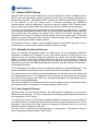
MEA
3.1
Vehicle Mounted
Modem
Users Guide
Documentation Revision 3.1.7
Mesh Enabled Access
VMM Users Guide
Copyrights
The Motorola products described in this document may include copyrighted Motorola computer programs. Laws in the
United States and other countries reserve for Motorola certain exclusive rights for copyrighted computer programs.
Accordingly, any copyrighted Motorola computer programs contained in the Motorola products described in this
document may not be copied or reproduced in any manner without the express written permission of Motorola.
Furthermore, the purchase of Motorola products shall not be deemed to grant either directly or by implication,
estoppels or otherwise, any license under the copyrights, patents or patent applications of Motorola, except for the
normal nonexclusive, royalty-free license to use that arises by operation of law in the sale of a product.
Disclaimer
Please note that certain features, facilities and capabilities described in this document may not be applicable to or
licensed for use on a particular system, or may be dependent upon the characteristics of a particular mobile
subscriber unit or configuration of certain parameters. Please refer to your Motorola contact for further information.
Trademarks
Motorola, the Motorola logo, and all other trademarks identified as such herein are trademarks of Motorola, Inc. All
other product or service names are the property of their respective owners.
Copyrights
© 2007 Motorola, Inc. All rights reserved. No part of this document may be reproduced, transmitted, stored in a
retrieval system, or translated into any language or computer language, in any form or by any means, without the
prior written permission of Motorola, Inc.
i
Mesh Enabled Access
VMM Users Guide
Table of Contents
1
PRODUCT INTRODUCTION ................................................................................... 1
1.1
2
Product Contents ......................................................................................................1
DEVICE INSTALLATION ......................................................................................... 2
2.1
Software Requirements ............................................................................................2
2.2
Equipment Requirements.........................................................................................2
2.3
MAC Address Label Location ..................................................................................3
2.3.1
MAC Address Table ..................................................................................................... 3
2.4
VMM6300 Assembly Information .............................................................................4
2.5
Installing the VMM6300 Device ................................................................................4
2.5.1
Deployment Considerations ......................................................................................... 5
2.5.1.1 Deployment Tips.............................................................................................. 5
2.6
3
Testing the Device Installation.................................................................................5
DEVICE CONFIGURATION ..................................................................................... 7
3.1
IP Addressing Considerations .................................................................................7
3.2
Accessing the MEA Device Administration Web Pages........................................7
3.2.1
Administrator and Access Account Information............................................................ 7
3.2.1.1 Password Information...................................................................................... 8
3.2.2
Viewing MEA Device Administration Redirect Page .................................................... 9
3.2.3
Viewing MEA Device Administration Home Page as an Administrator...................... 10
3.2.4
Viewing MEA Device Administration Home Page as a Normal User......................... 11
3.2.5
VMM Device Administration Configuration Tab.......................................................... 12
3.2.5.1 Viewing the VMM Configuration Tab as an Administrator............................. 12
3.2.5.2 Viewing the VMM Configuration Tab as a Normal User................................ 13
3.2.6
VMM Device Administration Geo Position Tab .......................................................... 14
iii
3.3
Device Addressing Schemes .................................................................................15
3.3.1
Network DHCP Scheme ............................................................................................. 16
3.3.2
Statically Provisioned Scheme ................................................................................... 16
3.3.3
User Supplied Scheme............................................................................................... 16
3.4
Setting User Supplied IP Addresses .....................................................................17
3.5
External Device Provisioning.................................................................................19
3.5.1
3.6
4
Connecting to the Ethernet Port ................................................................................. 20
Working with MeshTray ..........................................................................................20
3.6.1
MeshTray Status Information ..................................................................................... 21
3.6.2
MeshTray Security Tab .............................................................................................. 22
3.6.3
MeshTray Authentication Activity ............................................................................... 22
DEVICE MAINTENANCE....................................................................................... 24
4.1
Changing the Web Interface Password.................................................................24
4.2
Upgrading the Device Firmware ............................................................................26
4.3
Security Provisioning Web Page ...........................................................................28
4.3.1
Provision Username Section ...................................................................................... 28
4.3.2
Provision Groupname Section.................................................................................... 28
4.4
Resetting the VMM via the Device Administration Web Page.............................29
4.5
Restoring Factory Settings – User Supplied Mode Limitations..........................31
4.5.1
Recovering from VMM Reset-to-Default in User-Supplied Mode............................... 31
4.5.1.1 Resetting Device Addressing Mode Using Device Manager......................... 31
4.5.1.2 Resetting Device Addressing Mode via Configuration Web Page ................ 31
4.5.1.3 Resetting User-Supplied Parameters via Configuration Web Page.............. 31
4.6
5
Restoring Factory Settings – Normal Operations ................................................32
CUSTOMER SERVICE INFORMATION ................................................................ 34
5.1
Obtaining Support...................................................................................................35
5.1.1
System Information..................................................................................................... 35
iv
Mesh Enabled Access
5.2
Vehicle Mounted Modem Users Guide
Return Material Request .........................................................................................35
5.2.1
Radio Products and Services Division ....................................................................... 35
5.2.1.1 Radio Products and Services Division Telephone Numbers......................... 36
5.2.2
Returning System Components to Motorola .............................................................. 36
5.2.3
Returning FREs .......................................................................................................... 36
6
WARRANTY INFORMATION................................................................................. 37
7
REGULATORY INFORMATION ............................................................................ 40
7.1
FCC Information ......................................................................................................40
7.2
FCC RF Energy Exposure Statement ....................................................................40
7.3
Regulatory and RF Safety Exposure .....................................................................40
v
List of Figures
Figure 2-1.
VMM External Connection Point ..................................................................4
Figure 2-2.
VMM6300 Trunk Mounting ............................................................................5
Figure 3-1.
Enter Network Password Initial Web Page Authentication Dialog............8
Figure 3-2.
MEA Device Administration Redirecting Web Page...................................9
Figure 3-3.
MEA Device Administration Home Page (Super User Login)..................10
Figure 3-4.
MEA Device Administration Home Page (Normal User Login)................11
Figure 3-5.
VMM Device Administration Configuration Page (Super User Login)....12
Figure 3-6.
VMM Configuration Page (Normal User Account) ....................................14
Figure 3-7.
Geo Position Tab (Same view for Super User and Normal accounts)....15
Figure 3-8.
Configuration Change Dialog.....................................................................17
Figure 3-9.
System Update Save Completed Web Page .............................................18
Figure 3-10.
External Device Provisioning Table...........................................................19
Figure 3-11.
MeshTray Status Tab (VMM).......................................................................21
Figure 3-12.
MeshTray Security Tab (VMM) ...................................................................22
Figure 3-13.
MeshTray Authentication Activity tab (VMM) ...........................................23
Figure 4-1.
Enter New Password Web Page.................................................................24
Figure 4-2.
Confirm Changes Window for Enter New Password ...............................25
Figure 4-3.
Password Changed Confirmation Web Page............................................25
Figure 4-4.
Update Device Firmware Web Page...........................................................26
Figure 4-5.
Confirm Upload Window for Firmware Update .........................................27
Figure 4-6.
Firmware Upload Progress Web Page.......................................................27
Figure 4-7.
Security Provisioning Web Page ...............................................................28
Figure 4-8.
Device Reset Prompt Web Page ................................................................29
Figure 4-9.
Device Reset in Progress Page..................................................................30
Figure 4-10.
Restore Factory Settings Web Page..........................................................32
Figure 4-11.
Confirm Changes Window for Restore Factory Settings.........................33
Figure 4-12.
Factory Settings Restored Web Page........................................................33
vi
Mesh Enabled Access
Vehicle Mounted Modem Users Guide
1 Product Introduction
Thank you for purchasing the VMM6300 Vehicle Mounted Modem (VMM). The device is
designed to integrate with the Mesh Enabled Access (MEA) wireless communication system
capable of supporting high data rate mobile communication at variable rates of vehicular
speeds. This document provides detailed installation and configuration instructions for the MEA
VMM6300 device.
The VMM6300 is a wireless modem that has been designed for permanent in-vehicle mounting.
It provides access to the MEA network via an Ethernet connection to mobile data terminals,
laptop computers, or any other device that has an Ethernet port. The VMM operates on 12VDC
and is rugged enough for installation in commercial and public safety vehicles. The VMM
provides the same functionality as the WMC6300 to the connected device, including geolocation.
The VMM efficiently combines the functionality of a MEA subscriber device and client modem
into a single cost-effective wireless network component. This makes it easy for any Ethernetready device to access a MEA mobile broadband network. Computers, IP video cameras,
sensors, signs, signals, etc. can all be Mesh Enabled to send and receive data at burst rates of
up to 6 Mbps. All standard subscriber device functionality including Multi-Hopping™, non-lineof-sight communications and geo-location services are fully supported.
The MEA Vehicle Mounted Modem allows connection of multiple IP addressable devices using
standard Ethernet connectivity. This allows devices that cannot accept the PCMCIA based
WMC6300 product to function transparently on a MEA network without additional drivers.
1.1
Product Contents
Each MEA VMM is a full-featured wireless networking device. The following is a list of the items
provided with each VMM:
•
•
•
•
MEA Vehicle Mounted Modem (flange mount)
15 foot cable assembly
1 Mag Mount 0 dBi antenna.
1 N-type to SMA adapter
1
2 Device Installation
2.1
Software Requirements
Two types of software interfaces will be required during the installation and setup process of the
VMM3600 device: MeshManager and the VMM Device Administration web interface.
MeshManager software needs to be installed and running on a network computer prior to VMM
installation and configuration. MeshManager will be used in the VMM setup process to validate
the installation of the device. In addition, MeshManager will be used to manage a VMM and
other subscriber devices within the MEA network.
The VMM Device Administration web interface is used to administer and configure the device
and can be accessed by connecting a PC to the wired interface. Additional information is
provided later in the manual.
Detailed information about MeshManager software and its usage is found in the following
publications: MeshManager User’s Guide and QuickStart for MeshManager.
2.2
Equipment Requirements
A VMM6300 is utilized similarly to a subscriber device within a MEA network and will be used
with the IAP6300 and MWR6300 infrastructure devices.
The following list defines the standard MEA hardware components to install a VMM:
• N-type Antenna Connector
• 0dBi Antenna (supplied)
• 15 foot cable assembly
The Network Operator must supply the following:
• Mounting Location
• Power Source (12V DC) (from vehicle or other DC power supply)
• A Hub or Switch (if more then 1 Ethernet device will be used)
• Hand tools for bracket installation
2
Mesh Enabled Access
2.3
Vehicle Mounted Modem Users Guide
MAC Address Label Location
The transceiver and SBC (Ethernet) MAC addresses are listed on the label located on the back
side of the VMM unit. Record these numbers in the MAC Address Table provided in the next
section.
2.3.1 MAC Address Table
The MAC Address table has been included for recording the Ethernet MAC address and
transceiver MAC address for a set of VMM devices as a quick reference. These addresses will
be required later in the configuration and management process.
Write the MAC numbers into the MAC Address Table provided below.
MAC Address Table
MAC Address (00-05-12-0A-xx-yy)
ETH MAC Address (00-05-12-30-xx-yy)
3
2.4
VMM6300 Assembly Information
The VMM6300 Assembly shows the external connection points on a VMM6300 box.
Power
Connector
Power
Reset
N-Type
Antenna
Connector
Ethernet
(Crossover MDI-X)
Figure 2-1.
2.5
VMM External Connection Point
Installing the VMM6300 Device
The following instructions describe the VMM6300 hardware installation procedure:
1. Mount the VMM box in a suitable location in a vehicle to allow for ventilation. Note
that the device is not waterproof and should be reasonably protected from moisture
and other exposed outdoor environments.
2. Connect the antenna to the N-type connector.
3. Insert the Power Plug into Power Connector.
4. Verify that both MAC addresses have been recorded in Section 2.3.1, as this
information will be required to configure and test the device.
5. If installing more than one IP device to the VMM6300, a separate hub device can be
connected to the VMM ETH port. Up to three IP devices can be provisioned to
interface with the VMM.
NOTE: For more information about how to configure additional devices to the VMM,
refer to the External Device Provisioning section of this manual.
4
Mesh Enabled Access
Vehicle Mounted Modem Users Guide
Figure 2-2.
VMM6300 Trunk Mounting
2.5.1 Deployment Considerations
When deploying the VMM6300 consider the following:
• The antenna should be a minimum of 30 inches from any nearby metal poles to avoid
distortion of the RF pattern.
•
The antenna must have a separation distance of at least 2 meters from the body of all
persons and must not be co-located or operating in conjunction with any other antenna or
transmitter.
•
Users and installers must be provided with antenna installation and transmitter operating
conditions to satisfy RF exposure compliance.
•
Typically, Vehicle Mounted Modems are distributed within a network and are used as
subscriber devices. A rule of thumb is to deploy 2-3 hop networks to optimize range, latency,
and throughput to subscriber devices.
•
The VMM6300 installation location must provide applicable DC power for the device.
•
It is required that the VMM chassis be grounded to minimize the possibility of ESD
(electrostatic discharge) induced damage.
2.5.1.1
Deployment Tips
Locate the antenna to minimize multipath:
- Minimize interference from nearby transmitters
- Maximize chance of a direct line of sight connection to other devices.
- Mount the supplied antenna vertically
2.6
Testing the Device Installation
Verify the operation of the VMM6300 using the following procedure:
1. Apply power to the VMM6300 – power reset button will be illuminated to red.
5
2. Obtain the transceiver MAC address and the ETH address that was recorded earlier in
section 2.3.1. The address will be in the format 00-05-12-0A-xx-yy for the transceiver and
00-05-12-30-xx-yy for ETH.
3. From the MeshManager software screen, display the devices using the MAC address.
Note: This step assumes that the MeshManager software has been installed and running on
a networked computer.
4. Within the MeshManager software screen, select the appropriate VMM in the device tree.
5. Right-click on the device MAC address and select the Ping option.
A successful response to the Ping command verifies that the VMM is communicating to the
infrastructure devices.
6
Mesh Enabled Access
Vehicle Mounted Modem Users Guide
3 Device Configuration
3.1
IP Addressing Considerations
The VMM provides network access to one or more IP devices connected to the Ethernet port of
the VMM. In order for the VMM to provide service to the IP devices, some configuration must be
done prior to connecting the IP devices.
The local default gateway address is used only on the wired interface, and is only visible to the
attached IP devices. It is not advertised to the wireless network, and the network cannot access
the VMM using this gateway address. The VMM has another IP address for the wireless
interface that can be used to access the VMM from the network. Because the gateway address
is limited to the local wired interface, the same address could be used for the gateway service in
several VMM devices. The local gateway should be a part of the overall subnet chosen for your
MEA network.
Care must be taken to ensure that the selected IP address is on the same subnet and does not
conflict with any other devices or the chosen Local Gateway service address on the MEA
network.
3.2
Accessing the MEA Device Administration Web Pages
To modify the IP configuration for the VMM using the web interface, you must know the IP
address assigned to the VMM SBC. The mechanism for assigning the IP address is controlled
by the addressing mode of the VMM SBC. Regardless of the mechanism, the assigned IP
address can always be displayed using MeshManager.
If the factory setting is used, then the default addressing mode will be Remote DHCP, and the
VMM SBC IP address will be assigned by the network DHCP server.
If the SBC addressing mode was changed to Statically Provisioned, and an IP address was
entered, then the entered IP address will be used.
If the SBC addressing mode was changed to Statically Provisioned, but no IP address was
entered, then the default SBC IP address will be derived from the transceiver MAC address
(10.xx.yy.1, where the MAC address is 00:05:12:0A:XX:YY), similar to the default IP addresses
described in External Device Provisioning. XX and YY are hex values from the transceiver MAC
address, and the lowercase xx and yy are the same values in decimal. For example, a VMM
with a transceiver MAC address of 00:05:12:0A:80:20 would have a default SBC IP address of
10.128.32.1.
When the IP address is known, the device web page can be accessed by pointing your web
browser to the IP address of the VMM SBC. For example, if the VMM SBC address is
10.128.32.1, then the web page would be found at http://10.128.32.1/.
3.2.1 Administrator and Access Account Information
The device has two accounts for the web pages - an administrative account, and an access
account. The administrative account must be used for provisioning the device, and the access
account may be used for monitoring the status of the device.
NOTE: If you are running a VMM as a standalone device, the configuration web page can be
reached by connecting a PC to the wired interface. The installation procedure described here
requires administrator access. Alternatively, all of the parameters that are provisioned via the
7
web page may be provisioned via MeshManager instead.
3.2.1.1
Password Information
Administrator Password
The username is admin and the default (initial) password is admin.
The password for the admin account should be changed during installation.
Access (User) Password
The username is monitor and the default password is monitor.
The password for the Access account can be changed by the administrator.
Figure 3-1.
Enter Network Password Initial Web Page Authentication Dialog
8
Mesh Enabled Access
Vehicle Mounted Modem Users Guide
3.2.2 Viewing MEA Device Administration Redirect Page
After the login authentication has been completed, the web browser will display a redirecting
page, and your browser will automatically transition to the home web page for MEA Device
Administration.
Figure 3-2.
MEA Device Administration Redirecting Web Page
9
3.2.3 Viewing MEA Device Administration Home Page as an Administrator
The MEA Device Administration home page provides you with some basic information about
the device, including the IP addresses assigned to the device, the MAC addresses of the
device, the firmware revision number, and the reported link quality for the link to the IAP.
Additional web page links are available when logging-in as an Administrator (same as Super
User). In the Device Management section of the Home tab, the Administrator can:
•
Change Admin password
•
Change User password (Access Account)
•
Security Provisioning
•
Update Device Firmware
•
Restore Factory Defaults
•
Reset the Device
Figure 3-3.
MEA Device Administration Home Page (Super User Login)
10
Mesh Enabled Access
Vehicle Mounted Modem Users Guide
3.2.4 Viewing MEA Device Administration Home Page as a Normal User
The MEA Device Administration home page provides the Normal User (same as Access
Account) with some basic information about the device, including the IP addresses assigned to
the device, the MAC addresses of the device, the firmware revision, and the reported link
quality for the link to the IAP.
In the Device Management section of the Home tab, the Access Account User can:
•
Change User password
•
Reset the Device
Figure 3-4.
MEA Device Administration Home Page (Normal User Login)
11
3.2.5 VMM Device Administration Configuration Tab
Once you have accessed the MEA Device Administration home page, click on the Configuration
tab to display the IP address configuration.
3.2.5.1
Viewing the VMM Configuration Tab as an Administrator
The VMM Device Administration Configuration page when viewed as an Administrator (same
as Super User Login) allows for changes to the configuration of the VMM6300.
Figure 3-5.
VMM Device Administration Configuration Page (Super User Login)
The fields displayed in the Configuration tab are described in the following table.
12
Mesh Enabled Access
Vehicle Mounted Modem Users Guide
VMM Device Administration Page Fields (Administrator / Super User Login)
Field Name
Field Description
Field Default Value
System Name
This is the name of the device as shown by Assigned by
MeshManager
Network
Administrator
RDATE Server IP
Address
The IP address of the RDATE server. This is 172.31.0.20
usually the MiSC when operating in
infrastructure mode. The RDATE server
provides the current date to the VMM. The
VMM can operate without an RDATE server.
Wired Interface
Address
The VMM will tell the attached Ethernet devices MAC-derived
to use this address for the default gateway, and
the VMM will use the address when accessing
the local Ethernet segment.
Wired Interface
Subnet Mask
This is the subnet mask for the local Ethernet 255.255.0.0
segment.
DHCP Lease Time
This is the duration (in seconds) of the DHCP 300
leases that the VMM offers to the attached
Ethernet devices.
Device Priority
The Device Priority provisioning area allows the
operator to set the priority assigned to wireless
messages transmitted by this device. A priority
of 7 is the highest priority setting.
Geo Settings
The Geo Settings area allows the operator to Reporting Interval is
enable and disable the Geo Reporting feature set to 10 seconds.
(if provisioned), as well as control the
frequency of reports and provision the
destination server to which those Geo reports
will be sent. Requires entry of the primary Map
server’s IP address. The secondary Map
address is optional.
Levels
0-7
are
available, based on
your configuration as
set by the Network
Administrator
The External Device Provisioning frame of this web page is described in Section 3.5.
3.2.5.2
Viewing the VMM Configuration Tab as a Normal User
A similar screen will be displayed for the Access account (the web page will indicate Normal
User Login). Normal users can change only those settings for which they have system
privileges.
13
Figure 3-6.
VMM Configuration Page (Normal User Account)
3.2.6 VMM Device Administration Geo Position Tab
The geo position feature has to be provisioned on the destination or map server by the Network
Administrator.
Before any data can be viewed on the Geo Position tab:
1. The Enable Geo Position check box has to be checked on the Configuration tab, in the
Geo Settings section of the screen.
2. The map server’s IP address needs to be provided in the Primary Map Address field in
the Geo Settings section. The Secondary Map Address is optional.
For additional information about the Geo Location feature, refer to the MeshPositioning
Application Users Guide.
14
Mesh Enabled Access
Figure 3-7.
Vehicle Mounted Modem Users Guide
Geo Position Tab (Same view for Super User and Normal accounts)
The Geo Position tab displays readings of the VMM device when the feature is enabled. The
information contained on this screen will look the same to the Administrator and to the Access
User role.
3.3
Device Addressing Schemes
The concept of unified modes of operation centers on the current state of network
communication: Associated State and Unassociated State. In the associated state, the device is
using infrastructure equipment to communicate. In the unassociated state, the device operates
in peer-to-peer mode. There are three addressing schemes which allow the IT manager
increased flexibility in deployment: Network DHCP, Statically Provisioned, and User Supplied.
All of these schemes may be assigned per device, either by the user or by the network
manager. The network manager can also limit the user-selectable schemes or force a specific
scheme. Devices in each of these schemes can interoperate and communicate with each other,
so long as the assigned addresses do not conflict and are mutually routable.
15
3.3.1 Network DHCP Scheme
Network DHCP means that the VMM device can be configured to request an address from a
DHCP server and requires the inclusion of a DHCP server in the core network configuration to
answer these requests. With Network DHCP selected, the VMM will send DHCP requests for
its own address to the core network once it becomes associated and establishes
communications with the infrastructure. Operation under the Network DHCP scheme allows
users to temporarily wander outside of the network infrastructure without losing connectivity.
The server may be configured by the operator to hand out temporary or static leases. The VMM
must associate and acquire an address from the network before establishing communications.
Once a lease has been granted, the address will be valid out of network coverage for the
remainder of the lease or, if a static lease was granted, until the next power cycle. If the lease
expires or the user cycles power while outside of network coverage, the user will again lose the
ability to communicate with the wireless network.
This scheme is best for a larger, closely managed network of subscribers who don't need to
communicate or communicate only briefly outside of network coverage.
3.3.2 Statically Provisioned Scheme
Under the Statically Provisioned scheme, the VMM device will use provisioned DHCP-like
information to establish an IP address for use in the wireless network. A DHCP server is not
required on the core network because the addresses are derived from the MAC address by
default. It should be noted that a DHCP server can still exist on the network to hand out
addresses to other nodes using the Network DHCP Scheme as long as the server's address
range does not conflict with addresses assigned to devices using the Statically Provisioned or
User Supplied Schemes.
The IP addresses and options used are configurable per-device using MeshManager. The
provisioned address may be freely used to communicate while associated or unassociated.
The operator must ensure that the provisioned addresses are routable and do not conflict with
any other addresses in use. The operator is free to provision any option ordinarily provisioned
by a DHCP server (subnet mask, DNS, etc.) through programming of the appropriate fields in
each device using MeshManager.
This scheme is ideal for a managed network of users who regularly need to communicate inside
and outside of network coverage or for a network lacking a DHCP server.
3.3.3 User Supplied Scheme
Operating under the User Supplied scheme, the VMM device is configured to use a fixed IP
address and subnet mask. The user is responsible for configuring options that would otherwise
be configured by a DHCP server.
It is also up to the user to ensure that the assigned address is routable on the core network (if
core network access is needed) and that it does not conflict with other addresses in use. This is
analogous to and carries the same caveats as plugging an Ethernet card into a LAN and
manually assigning an address to the card.
The user is free to communicate while associated or unassociated. This scheme is ideal for
small, unmanaged networks lacking a DHCP server.
16
Mesh Enabled Access
3.4
Vehicle Mounted Modem Users Guide
Setting User Supplied IP Addresses
In order to set the user-supplied IP address for the VMM, the User-Supplied radio button must
be selected. At that point, the user may enter an IP address and subnet mask consistent with
the existing network. The user should also enter the IP address of the default gateway and DNS
server, as well as enter the domain name.
Note that this configures the user-supplied address for the VMM device. To configure addresses
for Ethernet clients, refer to the description in the External Device Provisioning section of this
guide.
A similar screen will be displayed for the access account (the web page will indicate Normal
User Login). Normal users can change only those settings for which they have system
privileges.
When the desired configuration has been completed, click on the Apply button on the Device
Addressing panel on the Device Administration Configuration Page. You will be prompted to
verify that the changes to the configuration are correct before the changes are actually applied.
Figure 3-8.
Configuration Change Dialog
When you click on the OK button, the configuration will be saved in flash. The System Settings
Have Been Saved message, on the System Update Save Completed page, will then confirm
that the changes have been saved.
17
Figure 3-9.
System Update Save Completed Web Page
After the settings have been saved, click the Finished button. Your web browser should return
to the MEA Device Administration home page. A reboot of the device is not required for the
changes to take effect.
18
Mesh Enabled Access
3.5
Vehicle Mounted Modem Users Guide
External Device Provisioning
The External Device Provisioning section of the VMM Device Administration page is used to
configure addresses for the attached nodes on the local Ethernet segment. Up to three
addresses are provisioned.
Figure 3-10. External Device Provisioning Table
The Enable checkbox indicates this row contains a valid address. Any address can be disabled
by clearing the checkbox. The pull-down menu options indicate whether this address will be
offered via the local DHCP service (“Local-DHCP”) or “Statically-Provisioned”.
The Statically-Provisioned setting is used to support devices that do not use DHCP to acquire
an address.
The MAC address field is used for Local-DHCP addresses, so that the IP address can be
reserved for a specific device. The reserved checkbox must be marked for this kind of IP
address reservation. The Status field indicates whether the provisioned IP address was
19
detected (via a ping) when the web page was brought up.
The IP addresses default to values based on the transceiver MAC address of the device. The
derivation is described below. By default, only the first IP address is enabled (for local-DHCP),
and no addresses are reserved for specific MAC addresses. Make sure to check the checkbox
for the client IP addresses you have entered. Client 2and Client 3 are not enabled by default.
The VMM has two interfaces and must use two IP addresses. The wireless network must use
the IP address on the wireless interface because that is the address for which the IAP will proxy
and advertise. The same address will be accessed by the Device Manager when using
MeshManager.
The wired interface address will be used by the VMM as the gateway address for the local
Ethernet segment. The wired subnet mask is configurable so that the user may select a more
restrictive subnet on the local Ethernet segment than what is normally provided to the wireless
subscribers.
The MAC-derived default values are a means to ensure that these devices are likely to work
out-of-the-box. The IP addresses are derived as follows:
Transceiver MAC address: 00:05:12:0A:XX:YY
Derived MAC addresses:
Local gateway:
10.xx.yy.9
Client1:
10.xx.yy.10
Client2:
10.xx.yy.11
Client3:
10.xx.yy.12
Where XX and YY are hex values (from the transceiver MAC address), and the lowercase xx
and yy are the same values in decimal. For example, a VMM with a transceiver MAC address of
00:05:12:0A:80:20 would have a default local gateway address of 10.128.32.9.
The user is encouraged to change these addresses upon installation.
3.5.1 Connecting to the Ethernet Port
If only one device is to be connected to the VMM, you can connect directly to the device using
an Ethernet cable.
If you are going to connect more than one device to the VMM, you will need to connect a hub to
the VMM, and connect the other devices to the hub.
3.6
Working with MeshTray
MeshTray™ is a status and configuration application that reports vital and statistical information
about the VMM. The application must be run on a client attached to the Ethernet port.
To start the MeshTray application, double-click on the MeshTray icon, or from the Start menu
select Programs Æ mea Æ MeshTray.exe.
For detailed information about using the MeshTray application, refer to the MeshTray section of
the MEA WMC6300 Windows Users Guide documentation.
20
Mesh Enabled Access
Vehicle Mounted Modem Users Guide
3.6.1 MeshTray Status Information
When the utility is launched, the MeshTray Status tab displays useful system information such
as a Description of the device, the MAC and IP address of the device, and the Type of device
(i.e., Vehicle Mounted Modem, Subscriber Device, etc.). The Firmware Version and Firmware
Build Date displayed here can be used to verify that the correct firmware revision is currently
loaded on the device, particularly after a firmware upgrade. The associated IAP MAC address
and the IAP Link Quality are also displayed.
Note: Viewing the Configuration tab in MeshTray from a laptop that is connected directly to a
VMM’s Ethernet port, will show the “Addressing Scheme” section as grayed-out, or not
available.
Figure 3-11. MeshTray Status Tab (VMM)
21
3.6.2 MeshTray Security Tab
The MeshTray Security tab allows for setting Open Authentication with Authentication Control
and provides IAP Authentication information, as well as Peer Authentication configuration.
The Peer Authentication section allows for adding and removing Group Names and each of their
passwords. There is a maximum of eight group names.
Figure 3-12. MeshTray Security Tab (VMM)
3.6.3 MeshTray Authentication Activity
The Authentication Activity tab displays any activity occurring between the VMM and the IAP
and between the VMM and another Subscriber device (Peer-to Peer). The Clear button can be
used to delete activities.
22
Mesh Enabled Access
Vehicle Mounted Modem Users Guide
Figure 3-13. MeshTray Authentication Activity tab (VMM)
23
4 Device Maintenance
4.1
Changing the Web Interface Password
When the Change Admin Password function is selected from the VMM Device Administration
Home Page by the administrator, or the Change User Password function is selected, the device
will present the following web page:
Figure 4-1.
Enter New Password Web Page
The operator is expected to enter a new password for the web account and click on the “submit”
button. Once the password entry is complete, the device will prompt the operator for
confirmation of the change.
24
Mesh Enabled Access
Figure 4-2.
Vehicle Mounted Modem Users Guide
Confirm Changes Window for Enter New Password
When the operator confirms the change, the new password will be stored in flash, and the
device will present a status screen indicating that the change was successful.
Figure 4-3.
Password Changed Confirmation Web Page
25
4.2
Upgrading the Device Firmware
The web interface for the device also provides the ability to upgrade the firmware on-site. To
use this feature, you must have an upgrade file from a released upgrade package.
When upgrading to version 7.5.0.0 from any prior SBC release via the web page, the web page
will show upgrade failure while the upgrade is still in progress in the background. In such cases,
there is no clear indication of when the upgrade is finished. It is recommended to perform an
upgrade via MeshManager and wait until the connection to the device (SNMP) is reestablished.
When the Upgrade Device Firmware function is selected from the MEA Device Administration
Home Page, the device will present the following web page:
Figure 4-4.
Update Device Firmware Web Page
This page allows entry of the name (and path) of the upgrade file. Once the correct filename has
been entered, the device will prompt for confirmation:
26
Mesh Enabled Access
Figure 4-5.
Vehicle Mounted Modem Users Guide
Confirm Upload Window for Firmware Update
Once the filename has been confirmed, the web browser will transmit the file to the device, and
the device will present an upgrade progress screen. This page will indicate the current stage in
the upgrade process.
Figure 4-6.
Firmware Upload Progress Web Page
Once the upgrade is completed, the device must be reset. The Finished button will transition the
web browser to the reset screen. See the Resetting the VMM via the Device Administration Web
Page section in this manual for additional information.
27
4.3
Security Provisioning Web Page
When the Security Provisioning option is selected from the VMM Device Administration Home
Page by the administrator, the device will present the following web page:
Figure 4-7.
Security Provisioning Web Page
The Security Provisioning web page contains two main sections: Provision Username and
Provision Groupname. Each item in both sections can be changed as needed.
4.3.1 Provision Username Section
Username – the username provided in this field is used to communicate to the IAP and can be
changed from this screen. If a new username is entered, the previous username is not retained.
Password and Re-enter new password – These two fields can be used to change the
password for an existing username, or to provide a password for a new username.
4.3.2 Provision Groupname Section
Groupname – the groupname provided in this field is used for peer-to-peer communication and
can be changed from this screen. If a new groupname is entered, the previous groupname is
not retained.
Password and Re-enter new password – These two fields can be used to change the
password for an existing Groupname, or to provide a password for a new Groupname.
28
Mesh Enabled Access
4.4
Vehicle Mounted Modem Users Guide
Resetting the VMM via the Device Administration Web Page
Although you should not have to reset the VMM device, the device can be commanded to reset
via the web pages. In order to reset the device, return to the MEA Device Administration home
page, and click on the Reset the Device link in the Device Management panel.
The web page displayed will allow you to reset the device.
Figure 4-8.
Device Reset Prompt Web Page
Once you have commanded the device to reset, the following screen will be displayed. Your
browser will delay for a short time, then transition to the home page once more.
29
Figure 4-9.
Device Reset in Progress Page
NOTE: After the completion of the reset, you may experience a significant delay when bringing
up another web page. Be patient.
30
Mesh Enabled Access
4.5
Vehicle Mounted Modem Users Guide
Restoring Factory Settings – User Supplied Mode Limitations
NOTE:
In Release 3 and 3.1, there is a known issue that arises if the selected device
addressing mode is User-Supplied when the user restores the factory default
settings for the VMM.
4.5.1 Recovering from VMM Reset-to-Default in User-Supplied Mode
After restoring factory defaults, the VMM’s addressing scheme is automatically set to Network
DHCP. This causes the network connection between the attached Ethernet devices and the
core network to become disabled.
There are three available options to recover from this situation and restore the connection to the
core network.
4.5.1.1
Resetting Device Addressing Mode Using Device Manager
Device Manager will be able to manage some but not all of the device parameters at this time.
The network operator may change the selected device addressing mode via Device Manager to
either User-Supplied or Statically-Provisioned.
4.5.1.2
Resetting Device Addressing Mode via Configuration Web Page
Because the factory default settings were restored, the VMM will offer one IP address via
DHCP. This address will be in the form 10.xx.yy.10, where xx and yy are based on the
transceiver MAC address as described in section 3.2 of this manual. The VMM will be
accessible via the 10.xx.yy.9 address. Once an Ethernet device has been attached to the VMM,
the configuration web page may be accessed at the 10.xx.yy.9 address and the device
addressing mode may be changed to either Remote-DHCP or Statically-Provisioned.
Be aware that the access password for the web page will have also been reset.
4.5.1.3
Resetting User-Supplied Parameters via Configuration Web Page
If the allowed device addressing modes were restricted to User-Supplied, the user may still
connect to the VMM (as described above) and access the configuration web page. The UserSupplied parameters may then be set to usable values.
31
4.6
Restoring Factory Settings – Normal Operations
When the Restore Factory Defaults function is selected from the VMM Device Administration
Home Page, the device will present the following web page.
Figure 4-10. Restore Factory Settings Web Page
The Restore Factory Defaults function allows the operator to return the device to factory
defaults. This change will include the web password for the administrator and access accounts.
This will also return the local IP addresses to the default MAC-derived values.
The confirmation window will be displayed. Click on the OK button to confirm the action.
32
Mesh Enabled Access
Vehicle Mounted Modem Users Guide
Figure 4-11. Confirm Changes Window for Restore Factory Settings
The Factory Settings Restored page will be displayed.
Figure 4-12. Factory Settings Restored Web Page
Click on the Finished button to complete the reset procedure.
33
5 Customer Service Information
If you have read this document and made every effort to resolve installation or operation issues
yourself and still require help, please contact your regional Motorola support representatives
USA
Motorola System Support Center (SSC) using the following contact information:
Phone: 800-221-7144
Hours of Operation: 7 days a week, 24 hours
Europe
Phone: +44 (0)1793 564680
Email: [email protected]
Hours: of Operation: Mon-Fri 09:00 - 17:00 GMT
Calls are logged 24 x 7, cases will be worked Mon-Fri 09:00 - 17:00 GMT
Asia and Pacific Region
Remote Technical Help Desk (Channel Partners)
Phone: +63 28 92 79 93
Email: [email protected]
Hours of Operation: Mon - Fri 8 am - 6 pm
Sat 8 am - 12 noon
34
Mesh Enabled Access
5.1
Vehicle Mounted Modem Users Guide
Obtaining Support
Motorola provides technical support services for your system and recommends that you coordinate
warranty and repair activities through the Motorola System Support Center (SSC). When you consult
the Motorola SSC, you increase the likelihood that problems are rectified in a timely fashion and that
warranty requirements are satisfied. Check your contract for specific warranty and service information.
5.1.1 System Information
To be provided with the best possible opportunity for support, collect the following system information
and have it available when obtaining support.
5.2
•
Location of the system
•
Date the system was put into service
•
Software or firmware version information for components of your system
•
Serial number(s) of the device(s) or component(s) requiring support
•
A written description of the symptom or observation of the problem:
-
When did it first appear?
-
Can it be reproduced?
-
What is the step-by-step procedure to cause it?
•
Do other circumstances contribute to the problem? For example, changes in
weather or other conditions?
•
Maintenance action preceding problem:
-
Upgrade of software or equipment
-
Change in the hardware or software configuration
-
Software reload - from backup or from CD-ROM (note the version and
date)
Return Material Request
After collecting system information, contact the Motorola System Support Center for assistance or to
obtain a Return Material Authorization (RMA) number for faulty Field Replaceable Entities (FREs):
North America: 800-221-7144
5.2.1 Radio Products and Services Division
The Radio Products and Services Division is your source for manuals and replacement parts.
35
5.2.1.1
Radio Products and Services Division Telephone Numbers
The telephone numbers for ordering are: (800)-422-4210 (US and Canada orders)
The Fax numbers are: (800)-622–6210 (US and Canada orders)
The number for help identifying an item or part number is (800)-422-4210; select choice “3” from the
menu
5.2.2 Returning System Components to Motorola
Motorola's service philosophy is based on field replaceable entities (FREs). FREs are system
components identified by Motorola to be returned to Motorola for repair.
5.2.3 Returning FREs
Return faulty FREs to Motorola for repair. When you return an assembly for service, follow these best
practices:
•
Place any assembly containing CMOS devices in a static-proof bag or container
for shipment.
•
Obtain a return authorization (RA) number from the Motorola System Support
Center.
•
Include the warranty, model, kit numbers, and serial numbers on the job ticket,
as necessary.
•
If the warranty is out of date, you must have a purchase order.
•
Print the return address clearly, in block letters.
•
Provide a phone number where your repair technician can be reached.
•
Include the contact person's name for return.
•
Pack the assembly tightly and securely, preferably in its original
shipping container
36
Mesh Enabled Access
Vehicle Mounted Modem Users Guide
6 Warranty Information
This warranty applies within the fifty (50) United States, the District of Columbia and Canada.
LIMITED WARRANTY
MOTOROLA COMMUNICATION PRODUCTS
If the affected product is being purchased pursuant to a written Communications System
Agreement signed by Motorola, the warranty contained in that written agreement will apply.
Otherwise, the following warranty applies.
I. WHAT THIS WARRANTY COVERS AND FOR HOW LONG:
Motorola Inc. or, if applicable, Motorola Canada Limited ("Motorola") warrants the Motorola
manufactured Broadband Data communications product, against material defects in material and
workmanship under normal use and service for a period of One (1) Year from the date of
shipment.
Motorola, at its option, will at no charge either repair the Product (with new or reconditioned
parts), replace it with the same or equivalent Product (using new or reconditioned Product), or
refund the purchase price of the Product during the warranty period provided purchaser notifies
Motorola according to the terms of this warranty. Repaired or replaced Product is warranted for
the balance of the original applicable warranty period. All replaced parts of the Product shall
become the property of Motorola.
This express limited warranty is extended by Motorola to the original end user purchaser
purchasing the Product for purposes of leasing or for commercial, industrial, or governmental
use only, and is not assignable or transferable to any other party. This is the complete warranty
for the Product manufactured by Motorola. Motorola assumes no obligations or liability for
additions or modifications to this warranty unless made in writing and signed by an officer of
Motorola. Unless made in a separate written agreement between Motorola and the original end
user purchaser, Motorola does not warrant the installation, maintenance or service of the
Product.
Motorola cannot be responsible in any way for any ancillary equipment not furnished by Motorola
which is attached to or used in connection with the Product, or for operation of the Product with
any ancillary equipment, and all such equipment is expressly excluded from this warranty.
Because each system which may use the Product is unique, Motorola disclaims liability for
range, coverage, or operation of the system as a whole under this warranty.
II. GENERAL PROVISIONS:
This warranty sets forth the full extent of Motorola's responsibilities regarding the Product.
Repair, replacement or refund of the purchase price, at Motorola's option, is the exclusive
remedy. THIS WARRANTY IS GIVEN IN LIEU OF ALL OTHER EXPRESS WARRANTIES.
MOTOROLA DISCLAIMS ALL OTHER WARRANTIES OR CONDITIONS, EXPRESS OR IMPLIED,
INCLUDING THE IMPLIED WARRANTIES OR CONDITIONS OF MERCHANTABILITY AND FITNESS
FOR A PARTICULAR PURPOSE. IN NO EVENT SHALL MOTOROLA BE LIABLE FOR DAMAGES IN
EXCESS OF THE PURCHASE PRICE OF THE PRODUCT, FOR ANY LOSS OF USE, LOSS OF TIME,
INCONVENIENCE, COMMERCIAL LOSS, LOST PROFITS OR SAVINGS OR OTHER INCIDENTAL,
SPECIAL, INDIRECT OR CONSEQUENTIAL DAMAGES ARISING OUT OF THE USE OR INABILITY
TO USE SUCH PRODUCT, TO THE FULL EXTENT SUCH MAY BE DISCLAIMED BY LAW.
III. HOW TO GET WARRANTY SERVICE:
Purchaser must notify Motorola's representative or call Motorola's Customer Response Center at
1-800-247-2346 within the applicable warranty period for information regarding warranty service.
IV. WHAT THIS WARRANTY DOES NOT COVER:
37
A) Defects or damage resulting from use of the Product in other than its normal and customary
manner.
B) Defects or damage from misuse, accident, water, or neglect.
C) Defects or damage from improper testing, operation, maintenance, installation, alteration,
modification, or adjustment.
D) Breakage or damage to antennas unless caused directly by defects in material workmanship.
E) A Product subjected to unauthorized Product modifications, disassemblies or repairs
(including, without limitation, the addition to the Product of non-Motorola supplied equipment)
which adversely affect performance of the Product or interfere with Motorola's normal warranty
inspection and testing of the Product to verify any warranty claim.
F) Product which has had the serial number removed or made illegible.
G) Batteries (they carry their own separate limited warranty).
H) Freight costs to the repair depot.
I) A Product which, due to illegal or unauthorized alteration of the software/firmware in the
Product, does not function in accordance with Motorola's published specifications or with the
FCC type acceptance labeling in effect for the Product at the time the Product was initially
distributed from Motorola.
J) Scratches or other cosmetic damage to Product surfaces that does not affect the operation of
the Product.
K) That the software in the Product will meet the purchaser's requirements or that the operation
of the software will be uninterrupted or error-free.
L) Normal and customary wear and tear.
M) Non-Motorola manufactured equipment unless bearing a Motorola Part
Number in the form of an alpha numeric number (i.e., TDE6030B).
N) Lift trucks for installation, removal, replacement or repair of the Motorola supplied products
from light, power, telephone poles etc.
O) Dispatch to remote site locations
P) Loading of software upgrades or fixes into the devices.
V. GOVERNING LAW
In the case of a Product sold in the United States and Canada, this Warranty is governed by the
laws of the State of Illinois and the Province of Ontario, respectively.
VI. PATENT AND SOFTWARE PROVISIONS:
Motorola will defend, at its own expense, any suit brought against the end user purchaser to the
extent that it is based on a claim that the Product or its parts infringe a United States patent, and
Motorola will pay those costs and damages finally awarded against the end user purchaser in any
such suit which are attributable to any such claim, but such defense and payments are
conditioned on the following:
A) that Motorola will be notified promptly in writing by such purchaser of any notice of such
claim;
B) that Motorola will have sole control of the defense of such suit and all negotiations for its
settlement or compromise; and
C) should the Product or its parts become, or in Motorola's opinion be likely to become, the
subject of a claim of infringement of a United States patent, that such purchaser will permit
Motorola, at its option and expense, either to procure for such purchaser the right to continue
using the Product or its parts or to replace or modify the same so that it becomes non-infringing
or to grant such purchaser a credit for the Product or its parts as depreciated and accept its
return. The depreciation will be an equal amount per year over the lifetime of the Product or its
parts as established by Motorola.
Motorola will have no liability with respect to any claim of patent infringement which is based
upon the combination of the Product or its parts furnished hereunder with software, apparatus or
devices not furnished by Motorola, nor will Motorola have any liability for the use of ancillary
38
Mesh Enabled Access
Vehicle Mounted Modem Users Guide
equipment or software not furnished by Motorola which is attached to or used in connection with
the Product. The foregoing states the entire liability of Motorola with respect to infringement of
patents by the Product or any its parts thereof.
Laws in the United States and other countries preserve for Motorola certain exclusive rights for
copyrighted Motorola software such as the exclusive rights to reproduce in copies and distribute
copies of such Motorola software. Motorola software may be used in only the Product in which
the software was originally embodied and such software in such Product may not be replaced,
copied, distributed, modified in any way, or used to produce any derivative thereof. No other use
including, without limitation, alteration, modification, reproduction, distribution, or reverse
engineering of such Motorola software or exercise of rights in such Motorola software is
permitted. No license is granted by implication, estoppel or otherwise under Motorola patent
rights or copyrights.
39
7 Regulatory Information
7.1
FCC Information
This device complies with Part 15 of the FCC Rules. Operation is subject to the following two
conditions: (1) this device may not cause harmful interference, and (2) this device must accept
any interference received; including interference that may cause undesired operation.
Federal Communications Commission (FCC) Statement:
This Equipment has been tested and found to comply with the limits for a Class A digital device,
pursuant to Part 15 of the FCC rules. These limits are designed to provide reasonable
protection against harmful interference in a commercial installation. This equipment generates,
uses, and can radiate radio frequency energy and, if not installed and used in accordance with
the instructions, may cause harmful interference to radio communications. However, there is no
guarantee that interference will not occur in a particular installation. If this equipment does
cause harmful interference to radio or television reception, which can be determined by turning
the equipment off and on, the user is encouraged to try to correct the interference by one or
more of the following measures:
•
•
•
•
7.2
Reorient or relocate the receiving antenna.
Increase the separation between the equipment and receiver.
Connect the equipment into an outlet on a circuit different from that to which the receiver
is connected.
Consult the dealer or an experienced radio/TV technician for help.
FCC RF Energy Exposure Statement
1. This equipment complies with FCC RF Energy exposure limits set forth for an
uncontrolled environment.
2. This Transmitter must not be co-located or operating in conjunction with any other
antenna or transmitter.
Although this device complies with the FCC RF Exposure limits in multiple configurations of the
antenna, we suggest that the antenna be positioned away from the body when transmitting in
order to minimize the level of RF Exposure.
7.3
Regulatory and RF Safety Exposure
Your Motorola Wireless Network Device is designed and tested to comply with a number of
national and international standards and guidelines (listed below) regarding human exposure to
RF electromagnetic energy.
This product complies with the following RF energy exposure standards and guidelines:
• United States Federal Communications Commission, Code of Federal Regulations;
47CFR part 2 sub-part J
•
American National Standards Institute (ANSI) / Institute of Electrical and Electronic
Engineers (IEEE) C95. 1-2005
•
Institute of Electrical and Electronic Engineers (IEEE) C95.1-1999 Edition
•
International Commission on Non-Ionizing Radiation Protection (ICNIRP) 1998
40
Mesh Enabled Access
Vehicle Mounted Modem Users Guide
•
Ministry of Health (Canada) Safety Code 6. Limits of Human Exposure to
•
Radiofrequency Electromagnetic Fields in the Frequency Range from 3 kHz to 300 GHz,
1999
•
Australian Communications Authority Radiocommunications (Electromagnetic Radiation
– Human Exposure) Standard, 2003
•
ANATEL ANNEX to Resolution No. 303 of July 2, 2002 "Regulation of limitation of
exposure to electrical, magnetic and electromagnetic fields in the radio frequency range
between 9 KHz and 300 GHz" and "Attachment to resolution # 303 from July 2, 2002"
RF Exposure Compliance and Guidelines Operating Instructions
To ensure compliance with the general population uncontrolled environment RF exposure limits
in these standards, the antenna should be kept at a minimum separation distance of 20cm from
all persons when used in a personal or laptop computer.
ATTENTION
To ensure compliance with FCC requirements, use only Motorola approved, supplied antennas.
Use of non-Motorola approved antennas may result in non-compliance with FCC regulations.
NOTE: The manufacturer is not responsible for any unauthorized modifications to this
equipment. Unauthorized modifications could void user’s authority to operate
device.
41