1
FC700A
Fire detection system
Planning
Fire & Security Products
Siemens Building Technologies
Liefermöglichkeiten und technische Änderungen vorbehalten.
Data and design subject to change without notice. / Supply subject to availability.
Sous réserve de modifications techniques et de la disponibilité.
© 2004 Copyright by
Siemens Building Technologies AG
Wir behalten uns alle Rechte an diesem Dokument und an dem in ihm dargestellten Gegenstand vor. Der Empfänger anerkennt diese
Rechte und wird dieses Dokument nicht ohne unsere vorgängige schriftliche Ermächtigung ganz oder teilweise Dritten zugänglich machen
oder außerhalb des Zweckes verwenden, zu dem es ihm übergeben worden ist.
We reserve all rights in this document and in the subject thereof. By acceptance of the document the recipient acknowledges these rights
and undertakes not to publish the document nor the subject thereof in full or in part, nor to make them available to any third party without our
prior express written authorization, nor to use it for any purpose other than for which it was delivered to him.
Nous nous réservons tous les droits sur ce document, ainsi que sur l'objet y figurant. La partie recevant ce document reconnaît ces droits et
elle s'engage à ne pas le rendre accessible à des tiers, même partiellement, sans notre autorisation écrite préalable et à ne pas l'employer
à des fins autres que celles pour lesquelles il lui a été remis.
1
About this document ..............................................................................6
2
2.1
2.1.1
2.1.2
2.1.3
2.2
Safety regulations ...................................................................................8
Signal words and symbols ........................................................................8
Signal words and their meaning................................................................8
Symbols and their meaning ......................................................................8
Classification and meaning of additional symbols ....................................9
Safety-relevant working instructions .........................................................9
3
Main features .........................................................................................11
4
Technical data FC700A.........................................................................12
5
Logical and physical structure ............................................................13
6
6.1
6.2
6.2.1
Bus systems ..........................................................................................14
Bus overview...........................................................................................15
Modifying the impedance of the various C-Bus cables...........................15
Diagram...................................................................................................16
7
7.1
7.2
7.3
7.4
7.5
C-Bus stations.......................................................................................17
Station .....................................................................................................17
Types of stations .....................................................................................17
Hardware.................................................................................................17
Visualizer for Windows remote operation software (not available yet) ...18
Logical AREAS........................................................................................19
8
8.1
8.1.1
8.1.2
8.1.3
8.1.4
8.1.5
8.1.6
8.2
8.2.1
8.2.2
8.3
Limitations of C-Bus participants .......................................................20
Main CPU limits.......................................................................................20
Maximum number of devices ..................................................................20
Limits in the logical structure...................................................................20
Maximum number of criteria in zones control 4 and 6 ............................20
Maximum number of ZONE time channel...............................................20
Maximum number of I-Bus-modules .......................................................21
Limits of 5V supply ..................................................................................21
Control terminal limits (FC/FT)................................................................21
Limitation of visible texts on a FC700A...................................................21
Limitation of visible texts on a FT700A ...................................................21
Gateway limits (FG) ................................................................................22
9
Specify hardware required...................................................................23
10
10.1
10.2
10.3
Control unit FC700A .............................................................................24
Configuration...........................................................................................24
Block diagram .........................................................................................25
Modules...................................................................................................25
11
11.1
11.2
11.3
Auxiliary power supply.........................................................................26
Configuration...........................................................................................26
Block diagram .........................................................................................26
Modules...................................................................................................26
12
12.1
12.2
12.2.1
12.2.2
12.2.3
Control terminal B3Q700 (FC/FT) ........................................................27
Features ..................................................................................................27
Options....................................................................................................27
Plexiglas door to B3Q700 (FC/FT)..........................................................27
Place of the E3I020 RS232 module (FT) ................................................28
Place of the E3I040 LON interface (FT) .................................................28
3
Siemens Building Technologies
Fire & Security Products
007836_a_en_--.doc
03.2004
12.3
12.4
12.5
12.6
12.7
Installation possibilities (FT)....................................................................29
Block diagram .........................................................................................29
Connection lines between control unit and external operating units ......30
Power supply (24V).................................................................................30
Modules...................................................................................................31
13
13.1
13.2
Range of cabinets H23 / H26 / H28 ......................................................32
Recessed mounting H23G230 and H28G200 ........................................33
Modules...................................................................................................33
14
14.1
19” accessories.....................................................................................34
Modules...................................................................................................34
15
15.1
15.2
15.3
15.4
Line modules .........................................................................................35
Overview .................................................................................................35
Modules...................................................................................................35
Detection line "addressable" SynoLOOP................................................36
Detection line "collective" SynoLINE600/-Ex ..........................................37
16
16.1
16.2
16.3
16.4
Connection factors, line resistances and capacitances ...................38
Terminology and abbreviations ...............................................................38
Collective detection line ..........................................................................38
Addressable detection line ......................................................................38
Line resistance and capacitance.............................................................39
17
17.1
17.1.1
17.2
17.3
17.4
17.5
17.6
17.7
17.8
17.9
17.10
Control modules....................................................................................40
Application of control modules ................................................................40
Overview of the available modules with control outputs .........................40
Means of linking ......................................................................................40
Control outputs station type FC700A ......................................................41
Control outputs remote station type FT700A ..........................................41
Modules...................................................................................................41
CPU-overlapping controls .......................................................................42
Mimic Display panel outputs ...................................................................43
Modules...................................................................................................43
Relay outputs ..........................................................................................44
Modules...................................................................................................44
18
18.1
18.2
18.3
18.4
18.5
18.6
18.7
LON-Bus devices ..................................................................................45
Features ..................................................................................................45
LON-Bus as stub line ..............................................................................45
LON-Bus as free topology.......................................................................46
LON/Mimic Display p.c.b K3I050 ............................................................46
LON I/O card K3I110...............................................................................46
Indicator devices B3Q580 and B3Q590/595...........................................47
Modules...................................................................................................47
19
19.1
19.2
19.3
Gateway..................................................................................................48
Main features ..........................................................................................48
Application...............................................................................................48
Modules...................................................................................................49
20
Remote transmission............................................................................50
21
Printer interface.....................................................................................51
4
Siemens Building Technologies
Fire & Security Products
007836_a_en_--.doc
03.2004
21.1
21.2
21.3
21.4
Features ..................................................................................................51
Application variant FT .............................................................................51
Application variant FC.............................................................................51
Modules...................................................................................................51
22
22.1
22.2
22.3
22.4
22.5
22.6
22.7
22.8
Power supply.........................................................................................52
Concept...................................................................................................52
Special functions .....................................................................................52
Application...............................................................................................52
Power supply for the control unit.............................................................52
Auxiliary power supply ............................................................................52
Modules...................................................................................................53
Operation with power supply from control unit........................................53
Power supply for remote transmission equipment and accessories.......53
23
23.1
23.1.1
23.1.2
23.1.3
23.2
23.3
Emergency power supply ....................................................................54
Specifying battery capacity .....................................................................54
Battery rated capacity .............................................................................54
Ageing of battery .....................................................................................54
Calculation ..............................................................................................54
Capacity values for standard configurations...........................................54
Quiescent current table...........................................................................55
24
24.1
24.2
24.3
24.4
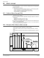
Alarm concept .......................................................................................56
Cerberus Alarm Concept (CAC) .............................................................56
Principle of the Cerberus alarm concept.................................................56
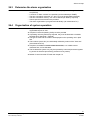
Determine the alarm organization...........................................................57
Organization of system operation ...........................................................57
25
Commissioning .....................................................................................58
26
26.1
26.2
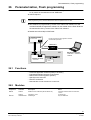
Parameterization, Flash programming ...............................................59
Functions.................................................................................................59
Modules...................................................................................................59
27
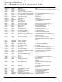
FC700A modules in alphabetical order ..............................................60
28
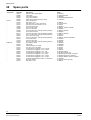
Spare parts ............................................................................................62
29
29.1
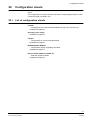
Configuration sheets ............................................................................63
List of configuration sheets .....................................................................63
30
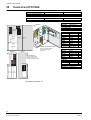
Control unit FC700A .............................................................................64
31
Auxiliary power supply.........................................................................65
32
Control terminal FT700A ......................................................................66
33
Display & operating terminals .............................................................67
34
Externally placed modules...................................................................68
5
Siemens Building Technologies
Fire & Security Products
007836_a_en_--.doc
03.2004
About this document
1
About this document
Purpose
This document describes the project planning of the hardware modules of the control unit FC700A. The consistent adherence to these instructions is a prerequisite
for a safe application.
Scope
This document contains information of all FC700A components, including part
numbers for ordering.
Target group
This product documentation and the work instructions are aimed at the following
persons, who have a particular function and have the corresponding training and
qualification.
Group of persons
Project Manager
Activity
The project manager is responsible for the local
project management. He co-ordinates the schedules of all groups of people working on a project
as well as resources. He also continuously obtains the technical information required for project
realization.
Qualification
He has had the technical training appropriate to
his function and the size of a project or the product line used in the project and has attended the
training courses for project managers at the supplier’s works.
Reference documents
Information in
007831
007827
007832
007835
007828
007833
007894
007895
Document
Hardware description
Installation housing H26... /H28...
Visualizer Customizing / End user (not yet available)
Operating instructions
Installation / Hardware Commissioning
Maintenance instructions
Templates for inscription stripes
Operating platform for Tools
Work and operational safety
Before personnel begin work on the system they must have read and understood the related operating
instructions, in particular chapter 2 ”Safety regulations”.
Disregard of the safety regulations
Before they are delivered, products are tested to ensure they function correctly
when used properly. Siemens disclaims all liability for damage or injuries caused
by the incorrect application of the instructions or disregard of warnings of danger
contained in the documentation. This applies in particular to:
– Personal injuries or damage caused by improper use and incorrect use;
– Personal injuries or damage caused by disregarding safety instructions in the
documentation or on the product;
– Personal injuries or damage caused by poor maintenance or a lack of maintenance.
6
Siemens Building Technologies
Fire & Security Products
007836_a_en_--.doc
03.2004
About this document
Conventions
(...)
..)
’’......’’ / ’.....’
->
Additional information
Notes
Definitions of designations
Details see page ...., chapter or document .....
Configuration sheets to fill out
Document identification
Place
Title page
Last page
bottom left
bottom right
Signification
– System names
– Product type
– Document purpose
– The document number consists of: Language, number, index
– Version date
– Manual
– Register
Modification index
Version
007836_a_en_--
Date
03. 2004
Brief description
First edition
7
Siemens Building Technologies
Fire & Security Products
007836_a_en_--.doc
03.2004
Safety regulations
2
Safety regulations
This chapter describes the danger levels and the relevant safety regulations applicable for the use of our products. Please read the work instructions as well as the
chapter ”About this document” thoroughly before beginning any work.
2.1
Signal words and symbols
2.1.1
Signal words and their meaning
The danger level that is, the severity and probability of danger are indicated by the
signal words listed below. Non-observance may lead to the consequences indicated:
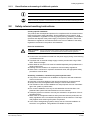
DANGER
Imminent danger!
May cause serious bodily injury or danger to life!
WARNING
Dangerous situation!
May cause serious bodily injury or danger to life!
CAUTION
Possibly dangerous situation!
May cause light injuries!
NOTE
Possibly harmful situation!
May cause damage to the product or to objects in the immediate vicinity of the
product!
2.1.2
Symbols and their meaning
The symbols listed below indicate the nature and origin of the danger.
Signal word
General danger
Signal word
Electrical voltage
Example for a danger warning
DANGER
External voltage
Disconnect the module from power supply.
8
Siemens Building Technologies
Fire & Security Products
007836_a_en_--.doc
03.2004
Safety regulations
2.1.3
Classification and meaning of additional symbols
Tips and information
Refers to extremely important or critical decisions to be taken into account before continuing the work.
2.2
Safety-relevant working instructions
Country-specific standards
The products are developed and produced in compliance with the relevant international and European safety standards. Should additional country-specific, local
safety standards or regulations concerning project planning, assembly, installation,
operation and disposal of the product apply in the place of operation, then these
standards or regulations must also be taken into account in addition to the safety
regulations mentioned in the product documentation.
Electrical installations
DANGER
Work on electrical
installations
Any work on electrical installations may only be carried out by qualified electricians or instructed persons working under the guidance and supervision of a
qualified electrician, in accordance with the electro technical regulations.
Control units must be disconnected from the power supply during commissioning
or maintenance work.
Terminals with an external voltage supply must be provided with a sign ”DANGER - External voltage”.
Mains leads to the control unit must be installed separately and provided with a
clearly marked fuse.
Earthing must be carried out in compliance with local safety regulations.
When work is carried out in explosion-hazardous areas, the appropriate safety
precautions must be taken.
Assembly, installation, commissioning and inspection work
If any tools or accessories such as ladders are required, safe and suitable devices must be used.
Prevention of spurious tripping of the remote transmission must be assured.
Always inform the fire brigade before testing the remote transmission.
The activation of fire control installations for test purposes must not cause damage to the system or parts thereof.
Fire control installations must only be activated after the test has been completed and the system has been handed over to the customer.
Third party systems or devices must only be activated in the presence of the responsible person.
When work on management stations and system terminals are performed, the
safety regulations of the connected sub-systems must be observed. This especially applies when switching-off system components.
In the case of extinguishing systems, always use the ”General installation instructions” as a guideline. This guideline is available on request.
9
Siemens Building Technologies
Fire & Security Products
007836_a_en_--.doc
03.2004
Safety regulations
Testing the product operability
Evacuate and cordon off extinguishing sector.
Inform people about the possibility of occurring fog and noise.
Inform people before testing of alarm devices; take the possibility of panic reactions into account.
Inform the alarm and fault receiving stations connected to the system before
running the tests.
Modifications to the system design and the product
Modifications to a system or to individual products may cause faults or malfunctioning.
Please request written approval from us, and the relevant authorities concerning intended system modifications and system extensions.
Modules and spare parts
Locally procured modules and spare parts must comply with the technical specifications laid down by the manufacturer. This compliance is always ensured for
original spare parts supplied by us.
Only use fuses with the specific fuse characteristics.
Wrong battery types and improper battery exchange may introduce the danger
of explosion. Only use the specified battery type or an equivalent battery type
recommended by the manufacturer.
Batteries require environmentally safe disposal. They must be handed in at the
local collecting points.
Please take into account that the extinguishing agent cylinders are pressurized
and must be exchanged in compliance with the local safety regulations.
10
Siemens Building Technologies
Fire & Security Products
007836_a_en_--.doc
03.2004
Main features
3
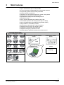
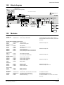
Main features
Fire detection system for modular configuration
Up to 1000 detectors per FC700A possible
For the processing of addressable and conventional detectors
Logical and physical structure totally separated
Control console as main CPU
Interfaces for VdS peripheral equipment, printer, host systems
Different types of input and output modules
Special Mimic Display terminal activating module
Multidetector logic
Up to 16 free selectable type of stations per C-Bus
Comfortable operation with soft keys and large LC display
Up to 64 independent logical AREAS (Organization levels)
Single-AREA or multi-AREA operation
Event memory with sub-menu / search functions
Integrated real time clock with auxiliary battery
Automatic summer/winter time switchover
Integrated emergency operation function
Flexible detector parameters setting via maintenance PC
Connectible detector systems
Synova™ 300/600, Special detectors
Stations
Control terminal / Main-CPU ‘FC700A’
B3Q700
Control terminal ‘FT700A’
B3Q700
SynoLOOP
CPU
WINDOWS based
Configuration software
®
D
pe
Ty
S
Cerberu
s
SynoLINE300
01A
O11
- Ex
NS
ME
IE
EE x ib I
IC T
4
FG700A
Gateway
PTB N
r.
SynoLINE600 / SynoLINE600-Ex
SWE700A
Special detectors
11
Siemens Building Technologies
Fire & Security Products
007836_a_en_--.doc
03.2004
Technical data FC700A
4
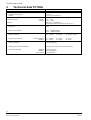
Technical data FC700A
Operating voltage
Power consumption
Battery operation in the event of mains failure
- Standard operating period
- Optional
Environmental conditions
Temperature during
115 / 230VAC
±15%
50... 60Hz
40... 220VA (per converter B2F020)
12...24h
Up to 72h (see chapter 23)
operation
Storage
Humidity
IP protection category (EN 60529 / IEC 529)
- Control unit
IP50
- Remote control terminal
IP52
IP40
Dimensions
- Control unit cabinet
- Separate control terminal
0°C... +40°C
-20°C... +60°C
Max. 95%, no condensation
Complies with class 3K5 according to IEC 721–3–3
in cabinet H26G220
H28G200
H26G220 cabinet
H28G200 cabinet
W = 520mm,
H = 602mm,
D = 100mm / 155mm
W = 366mm,
W = 520mm,
H = 219mm,
H = 300mm,
D = 76mm
D = 70mm
Colors
- Control unit cabinet
RAL 7035 light grey
- Operating unit front terminal B3Q700
Dark grey like Pantone 431C, Pantone 429C grey
- Control terminal cabinet
H26G220
H28G200
H28T110/120
Pantone 421 grey
RAL 7035 light grey
1E110 dark grey
12
Siemens Building Technologies
Fire & Security Products
007836_a_en_--.doc
03.2004
Logical and physical structure
5
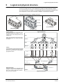
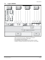
Logical and physical structure
In the FC700A fire detection system, the logical structure is completely separated
from the physical structure. This enables the greatest possible flexibility. Display
and control terminal are based on the geographical and organizational aspects and
are independent of the actual hardware installation of the detector network.
Geographical features (-> building structure)
1st floor
2nd floor
Room 101
1st floor
Room 102
Room 103
ground floor
Room 104
Room 104 (Zone)
Main building (Area)
st
1 floor (Section)
Logical structure
The logical structure is a configuration of the
geographical features of a system. It can be
modified easily to the building structure, room
utilization etc.
Area
Within the same control unit the logical structure is independent of the wiring of the detector network.
Section
logical structure
Zone
Main
building
Ground
floor
Ware
house
2nd
floor
1st
floor
Room
102
Reception
Room
103
Room
104
Canteen
EDP
room
Element
Linking
The lowest levels of both structures are linked
to each other. It is determined which physical
devices (e.g. detectors) are in which logical or
geographical location.
Linking
Level 2
Level 1
Device
Level 2
SynoLOOP
Line 2
Line 3
Line 1
Line 4
Line modules E3M111
Level 1
Function unit
Physical structure
The physical structure is a configuration of the
hardware. It results from the hardware installation. The number of used levels is depending on the type of hardware.
I-Bus
C-Bus
Control unit ‘FC’
Control terminal ‘FT’
Station
physical structure
13
Siemens Building Technologies
Fire & Security Products
007836_a_en_--.doc
03.2004
Bus systems
6
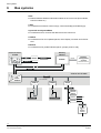
Bus systems
In the FC700A fire detection system there are 5 communication levels:
I-Bus
Internal data bus between individual modules in the control unit (line modules,
control modules etc.)
C-Bus
Local data bus between control unit(s), control terminal(s) and Gateway(s)
SynoLOOP and SynoLINE600
Local detector bus; connects the detectors to the control unit
LON-Bus
Local data bus for floor repeater panels, mimic display converter and LON I/O
card
Data Bus
Local data bus for parallel indicator panel, synoptic panel or relay
Gateway
FG700A
Control terminal
FT700A
E3I040
I-Bus
LON-Bus
RS232
E3H020
Databus
Building
management
system
ISO1745 Protocol
C-Bus
Control unit FC700A
I-Bus
CPU
B3Q700
Line modules
E3M111
E3M080
E3I040
LON-Bus
B3Q580/
B3Q590/
B3Q595
SynoLOOP
SynoLINE600
K3I110
In-/Outputs
K3I050
Databus
B3R051
or
K3R072/
K3G060
14
Siemens Building Technologies
Fire & Security Products
007836_a_en_--.doc
03.2004
Bus systems
6.1
Bus overview
Features
Field of application
C-Bus
I-Bus
SynoLOOP
SynoLINE600
LON-Bus
Local system bus
Inside control unit
For addressable
detectors
For collective
detectors
Local data bus
for floor indicator
panels
57kBaud
1000kBaud
2 messages/sec
(Direct current
signal)
78kBaud
Max. 1000m
(G51 ∅ 0,8: 1400m)
Max. 3m (only
inside cabinet)
Max. 150Ω/300nF
See chapter 16
Max.
150/250Ω/4µF
See chapter 16
… 16
C-Bus devices
… 16
I-Bus modules
… 128
D-Bus devices
1 address
(Max. 25 detectors)
Max. 500m as
free topology
Max. 1000m as
stub line
… 32
LON-Bus devices
2
(+3 wires for emergency operation)
26
2
2
2
6
(+3 wires supply)
Twisted 1)
Flat cable
Twisted
(Un-twisted
permissible)
–
Twisted
Twisted
–
Speed of transmission
Length of line
Number of users
connected or
addresses
Number of wires
Type of cable
Loop line
T-branch
Short-circuit proof
Network structure
Scanning
Principle
✔
–
Twisted
(Un-twisted permissible)
✔
–
–
–
Yes
Each user connected with line
separator
Master/master
Yes
Each user conNo
nected with line
separator
Master/slave
Master/slave
Master/slave
Cyclic
Event-controlled,
Cyclic,
- typ. all 64s
–
presence monitoring
Event controlled - Interrupt on
alarm
Sensor/actor-Bus
Serial Bus
Conventional
- Cerberus protoC-Bus
- Cerberus protocol
col 'K31'
- Current gain
- Cerberus protocol
- Collision detection
principle
- Serial 8bit
- SPI/Motorola
- Manchester coding
- Start-up: daisy- - Voltage levels
chain
1
6.2
–
Data Bus
Local data bus
parallel ind.
panel, synoptic
panel or relay
SPI-Bus 2KHz
Max. 1000m
… 24
Max. 8 addresses
–
✔
(See chapter 18)
No
–
–
Yes
Master/slave
Master/slave
Event-controlled,
presence moniCyclic
toring
- typ. all 250ms
(All 60s)
Network
- Echelon Chip
(LON protocol)
- Cerberus
specific telegram
Serial bus
- Cerberus protocol
Calibrated according to cable impedance: 50Ω (MICC) / 110Ω (G51, ø
0.8mm, not shielded)
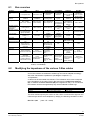
Modifying the impedance of the various C-Bus cables
C-Bus standard cables have a characteristic impedance of 110Ω. The driver and
end-of-line resistors are soldered to solder lugs and can be adapted accordingly
with other characteristic impedances (see diagram chapter 6.2.1).
1. Explanation
A cable must be terminated with resistors. The resistance value must correspond
to the impedance of the cable. Each C-Bus user has four end-of-line resistors
(Ri). In addition two driver resistors (Rd) are integrated on the p.c.b. In order that
the resistors can be exchanged easily they are all soldered to solder lugs.
C-Bus p.c.b.
B3Q700
E3H020
Ri
R31 ... R34
R173, R174, R177, R178
Rd
R49, R50
R180, R183
The driver resistors specify the current on the C-Bus. In order that the signal on the
C-Bus always has the same amplitude (1.35Vpp), the following correlation is valid:
Rd = Ri x 3,65
(45Ω < Ri < 200Ω)
15
Siemens Building Technologies
Fire & Security Products
007836_a_en_--.doc
03.2004
Bus systems
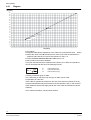
6.2.1
Diagram
Ri [Ohm]
200
190
180
170
160
150
140
130
120
110
Standard
100
90
80
Lifeline
70
60
Radox
50
MICC
40
30
20
10
0
0
20 40 60 80 100 120 140 160 180 200 220 240 260 280 300 320 340 360 380 400 420 440 460 480 500 520 540 560 580 600 620 640 660 680 700 720 740
Rd [Ohm]
2. Procedure
Request characteristic impedance of the cable from manufacturer (45Ω ... 200Ω)
Select the value of the Ri the same as the value of the cable characteristic impedance and insert the four end-of-line resistors on the p.c.b.
Insert two driver resistors Rd = Ri x 3.65 on the p.c.b.
Each C-Bus user must be adapted
If only the inductance and the capacitance are known for a cable, the impedance
can be calculated with the aid of the following formula:
Zc =
Lc
Cc
Zc:
Lc:
Cc:
Cable impedance [Ω]
Cable inductance [µH]
Cable capacitance [µF]
3. Mixing of different types of cable
In a C-Bus loop (or stub line) only one type of cable may be used.
4. Operation as a stub line
If the C-Bus is operated as a stub line, two end-of-line resistors (values as for Ri)
must be inserted externally at both ends of the line (default 110Ω). In the choice of
other cables the above rules apply (the Ri are in this case the external end-of-line
resistors).
For further information, see document 007831
16
Siemens Building Technologies
Fire & Security Products
007836_a_en_--.doc
03.2004
C-Bus stations
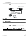
7
C-Bus stations
The C-Bus network contains max. 16 stations (user connected)
– Within the limits stated below (FC, FT, FG) are any stations in any arrangement
possible
– Max. 64 AREAS
Building mangement system
ISO1745 Protocol
Control terminal
FG700A
FT700A
Gateway
(max.15)
(max.15)
C-Bus Network
- max. 16 Stations
- 3 different types of stations
- loop line max. 1400m with G51 ø 0.8mm
C-Bus
Control terminal
Main-CPU
I-Bus
Line
modules
Control
modules
FC700A
(max.16)
Detector
7.1
Station
– Function unit within C-Bus network
– Several stations are be located in geographically dispersed cabinets
7.2
Types of stations
Differentiated by function and represented by a certain module
Certain modules can be used for different types of stations
Types of stations available:
Combination of main CPU and operating unit
Control terminal
Gateway (e.g. conversion of C-Bus Protocol -> ISO1745)
– FC700A
– FT700A
– FG700A
7.3
Hardware
Type of station
Module
FC700A
FT700A
FG700A
B3Q700
B3Q700
E3H020
Function
’Main CPU’
✔
–
Function
’Operation’
✔
✔
–
Function
’Gateway’
–
✔
17
Siemens Building Technologies
Fire & Security Products
007836_a_en_--.doc
03.2004
C-Bus stations
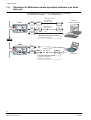
7.4
Visualizer for Windows remote operation software (not available yet)
– Operating platform requirements in detail see document 007895
– For details see document ……. (not available yet)
FC/FT
max. length of line
dependent on
type of modem
E3I020
E3I020
E3I020
Modem
Tel.
Modem
Dedicated line
temporary public
telephone line
Modem
Visualizer
Remote Operation
Tel.
Modem
(RS232) ....15m
Standard PC with keyboard, software
’Visualizer for Windows’,
C-BUS
FC/FT
B3D021
E3I020
Tel.
Modem
temporary public
telephone line
Tel.
Modem
(temporary)
e.g. Service Notebook, software
’Visualizer for Windows’,
SWE700A for Windows
18
Siemens Building Technologies
Fire & Security Products
007836_a_en_--.doc
03.2004
C-Bus stations
7.5
Logical AREAS
FC
1
2
3
FC
4
5
7
6
FC
8
..
..
..
FC
..
61
62
63
AREA
64
AREA
FC
FC
All AREAS control terminal
FG
–
–
–
–
–
FG
Within one main CPU (FC) max. 4 AREAS can be configured
CPUs cannot link up with AREAS of other CPUs
CPU overlapping controls are possible
Control terminals (FT) can be freely allocated to AREAS as required
Visibilities on gateways (FG) shall be set per station only, not per AREA!
19
Siemens Building Technologies
Fire & Security Products
007836_a_en_--.doc
03.2004
Limitations of C-Bus participants
8
Limitations of C-Bus participants
This chapter describes the quantitative limits of the FC700A station.
The selection of the station type depends on the requirements. The following variants are available:
SRAM
Soldered
EPROM set
RAM set
B3Q700
B3Q700
Flash ROM
(2x1024Kx8Bit)
'Program file'
CIY00760
CTY00760
4x512Kx8Bit
4x512Kx8Bit
–
–
E3H020
–
–
CKQ007.60
(2x512Kx8Bit)
–
–
2 x Z3S070
(2x512Kx8Bit)
(Assembly ex works)
Station type
Modules
FC700A
FT700A
FG700A
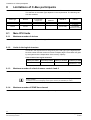
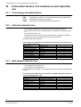
8.1
Main CPU limits
8.1.1
Maximum number of devices
1000 devices (with AMPK=1) per FC700A.
8.1.2
Limits in the logical structure
The limits in the logical structure are given by the node-type, by the highest possible CSX number and the maximum amount of display-digits. These limits are given
by the system and are independent of the memory capacity.
Table 'Limits of the logical structure'
Maximum rating
AREAS per STATION
... 4
8.1.3
Maximum rating
SECTIONS per AREA
…255
Maximum rating
ZONES per SECTION
…255
Maximum rating
ELEMENTS per ZONE
…99
International 5: …255
Maximum number of criteria in zones control 4 and 6
The maximum number of control zones with 16 criteria is limited by 200.
To optimize the performance of your system minimize the number of CPU-overlapping controls as
much as possible.
A maximum of 40 CPU-overlapping controls (zone control 6) are admissible per C-Bus.
8.1.4
Maximum number of ZONE time channel
Max. 16 ZONES time channel are permitted per station.
20
Siemens Building Technologies
Fire & Security Products
007836_a_en_--.doc
03.2004
Limitations of C-Bus participants
8.1.5
Maximum number of I-Bus-modules
Table 'Maximum number of I-Bus-modules'
Station type
FC700A
I-Bus modules
... 16 1)
... 8 2) 3)
1) Limited by software
2) Value based on experience (depends on cabinet size and/or 5V current consumption)
3) Battery charging unit E3C011 counts as one I-Bus module
8.1.6
Limits of 5V supply
All I-Bus modules are supplied with 24V and 5V. The available current for the 5V,
supplied from main CPU is limited:
'Main CPU'
B3Q700 / E3C011
Available current
250mA
Table '5V-Current consumption of I-Bus modules'
Current consumption
from 'Main CPU'
E3M080
55mA
E3M111
25mA
E3L020
10mA
E3L030
35mA
E3G050
8mA
* Not an I-Bus module, but supplied via the 'Main CPU'
I-Bus module
8.2
Control terminal limits (FC/FT)
8.2.1
Limitation of visible texts on a FC700A
I-Bus module
E3G060
E3G070
E3C011
E3I020*
E3I040
Current consumption
from 'Main CPU'
10mA
10mA
12mA
100mA
70mA
The number of texts of other stations (i.e. AREAS) that can be displayed on one
control terminal is limited by 14'000 texts.
To evaluate how many control panels FC700A can be displayed to one FC700A,
the following calculation must be used:
Twice the number of visible sections (worst case 1000)
+ The number of visible ZONES (worst case 1000)
+ The number of visible ELEMENTS with element text (worst case 1000)
= Number of texts per FC/FT (worst case 4000)
Example (worst case)
14'000 : 4000 (e.g.) = 3 fully configured FC can be displayed to one FC
8.2.2
Limitation of visible texts on a FT700A
The number of texts of other stations (FC700A) that can be displayed on one control terminal is limited by 14'000 texts.
To evaluate how many control panels FC700A can be displayed to one FT700A,
the following calculation must be used:
Twice the number of visible sections (worst case 1000)
+ The number of visible ZONES (worst case 1000)
+ The number of visible ELEMENTS with element text (worst case 1000)
= Number of texts per FC/FT (worst case 4000)
Example (worst case)
30'000 : 4000 (e.g.) = 7 fully configured FC can be displayed to one FT
21
Siemens Building Technologies
Fire & Security Products
007836_a_en_--.doc
03.2004
Limitations of C-Bus participants
8.3
Gateway limits (FG)
Via one gateway a maximum of 8 C-Bus stations (FC700A) can be addressed.
If more than 8 C-Bus stations (FC700A) are present, they must be split up on two
gateways.
Also for special applications, more than two gateways can be configured.
Visibilities of C-Bus stations (FC700A) on gateways must be set station wise, not
area wise!
22
Siemens Building Technologies
Fire & Security Products
007836_a_en_--.doc
03.2004
Specify hardware required
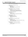
9
Specify hardware required
In order to be able to specify the hardware required, system key data must be
specified according the following procedure:
1. Specify number and type of detection lines
Dependent on:
– Detector series
– Number of detectors, input and output modules
– Building structure
2. Specify number and type of fire control installations
Dependent on:
– The fire protection installations to be activated
– Location of the contacts (centralized or decentralized)
– Individual types of contact (250VAC/10A or 30VDC/1A)
3. Specify number of operating units
Dependent on:
– Operating concept
– Parallel indicator panels, fire department control panels
4. Specify Accessories required
Dependent on:
– Printer interface and printer
– Remote transmission equipment
– Gateway, etc.
5. Specify emergency power supply battery capacity
Dependent on:
– Total quiescent current
– Required emergency current operating period (according to country)
– Type of remote transmission
6. Provide configuration sheet/sheets (see chapter 29)
Dependent on:
– Select sheets corresponding to the configuration
– Complete everything
23
Siemens Building Technologies
Fire & Security Products
007836_a_en_--.doc
03.2004
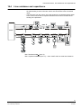
Control unit FC700A
10
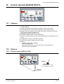
Control unit FC700A
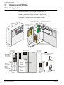
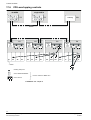
10.1
Configuration
Pre-assembled compact control unit
E3G070 and E3M111 are pre-wired on terminal block 'X1'
Place for additional terminal block 'X2', modules, relay and batteries
Batteries as required either 2x 12V/15Ah or 2x12V/27Ah
Control terminal built into front terminal (also serves as main CPU)
Installation of parallel indicator panel B3R051 possible
Door right hinged, can be locked with 2 Allen screws
Battery charging module
Control module ‘universal’
Line module ‘SynoLOOP’
520
Converter 115/230VAC
-> 29.6VDC/6A
Control terminal
Cover plate
602
Terminal block ‘X1’ with
2x20 terminals in two levels
147
155 incl. projecting door hinges
Module chassis
view 'Modules'
58
View A
recommended space
allocation
terminals
Z3B171
1
Z3B171
10
Z1K030
31
connection direct
(Akku 12V)
AX1201
or
AX1210
51
(Akku 12V)
AX1201
or
AX1210
B
A
X1
Z3I1060
57
pre-mounted and pre-wired
FC700A-1
23Mains
Z3I1050
X2
Z3I1060
E3....
Z1K or Z3I
56
E3....
Z1K or Z3I
E3....
Z1K or Z3I
E3H020
+ 2 x Z1K030
E3L030
+ 2 x Z1K or Z3I
48
E3....
Z1K or Z3I
E3....
Z1K or Z3I
E3H020 and
E3L030 requires
2 module spaces
47
E3....
Z1K or Z3I
46
B2F020
38
21
AC/DC converter
E3C011
Z3I470
37
E3M111
Z3I1050
E3G070
Z3I1050
EMC Precaution:
Slot rows with
E3C011 module
is not be allowed
with E3I040 module
28
E3I020
Z1K030
27
Module chassis
view ‘Terminals’
Cabinet front view
connection via terminal
block ‘X2’
View B
24
Siemens Building Technologies
Fire & Security Products
007836_a_en_--.doc
03.2004
Control unit FC700A
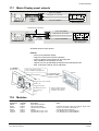
10.2
Block diagram
B3Q700 ‘FT’
(additional operating facilities)
RT = Remote transmission
Basic equipment
C-Bus
Option
Mains
B2F020
24V
24V
5V
FC700A
Batteries
AX12..
E3C011
24V
I-Bus
B3Q700
‘FC’
E3G070
24V
RS232
1
1........7
1..2
E3I020
B3R051
2
E3L030
E3M111
E3M080
1..........4
1.............8
E3G...
E3L...
Z3B171
LON-Bus
RT
250VDC / 10A
Fire control
installation
Printer
E3I040
FBF
FSK
LON synoptic converter
HM
VdS peripheral
equipment
SynoLINE600
SynoLOOP
K3I050
LON I/O card
K3I110
Floor repeater terminal
B3Q580/
B3Q59x
10.3
Modules
Component
Control unit
FC700A-1
Order-No.
Description
Notes
A5Q00004734
Control unit pre-assembled
Including B3Q700, H23B010, B2F020, E3C011,
Z3I470, E3G070, Z3I380, 2x Z3I1050, 1x Z3I1060
pre-wired
Control terminal, Parallel indicator panel
B3Q700
A5Q00004719
Control terminal
B3R051
490513
Parallel indicator panel
Details see chapter 12
LON-Bus devices
E3I040
499310
K3I050
496766
K3I110
528854
B3Q580
496177
B3Q590
496180
B3Q595
534110
LON interface
LON/Mimic Display converter
LON I/O card
Floor repeater panel
Floor repeater panel with control functions
Floor repeater panel with control functions
Details see chapter 18
Line modules
E3M111
E3M080
Line module SynoLOOP
Line module SynoLINE600/-Ex
Details see chapter 15
Control modules
E3G050
460255
E3G060
542539
E3G070
546661
E3L020
546645
Z3B171
484383
Control module 'Contacts'
Control module 'monitored'
Control module 'universal'
Control module 'Driver'
Relay module
Details see chapter 17
Interfaces
E3H020
E3I020
E3L030
460475
460239
475994
Gateway module
RS232 module
Control module VdS
Power supply
AX1201
AX1210
225487
475570
Battery 12V/27Ah
Battery 12V/15Ah
Accessories
Z3I1060
Z3I1050
Z1K030
Z3I380
A5Q00004722
A5Q00004717
484231
475567
Terminal block, 2x20 terminals in two levels
Connection cable 19 conductors
Terminal block with p.c.b. Chassis
Cable set I-Bus long
511531
460268
Details see chapter 19
Details see chapter 12 and 21
For additional modules
For connection via terminal 'X2'
To direct connection
To connect modules at the bottom with modules
at the top
25
Siemens Building Technologies
Fire & Security Products
007836_a_en_--.doc
03.2004
Auxiliary power supply
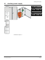
11
Auxiliary power supply
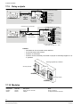
11.1
Configuration
Module chassis
view 'Modules'
27
absolutely essential
Cabinet front view
28
B2F020
Converter 115/230VAC
-> 29.6VDC/6A
E3C011
Battery charging module
H38G310
23
Mains
terminals
38
46
B2F020
E3C011
Z3I470
37
47
31
AX1201
A
or
48
AX1210
51
56
57
58
AX1201
or
AX1210
Z3I470
Cable set, terminal strip
with card holder
View A
AX1201 / AX1210
Batteries
11.2
Block diagram
* TF = Temperature sensor for battery temperature monitoring
Mains
Mains
FC700A
TF*
H38G310
Basic emergency
power supply
Batteries
AX12..
Extension
B2F020
B2F020
TF*
Batteries
AX12..
E3C011
Battery charging unit
Cascading
E3C011
Monitoring via HW monitoring path
Details see document 007831, chapter 'Cascading principle'
To activate the supervision path of the E3C011, the device "Fu supply ext. supply
supervision" must be created in the tool SWE700A.
11.3
Modules
Component
H38G310
B2F020
E3C011
Z3I470
AX1201
AX1210
Order-No.
484930
470588
505479
484341
225487
475570
Description
Housing set
Converter 115/230VAC -> 29,6VDC 6A
Battery charging unit
Cable set with card holder
Battery 12V / 27Ah
Battery 12V / 15Ah
Notes
Door without cut-out
Capacity based battery make 'ALARMCOM' (FIAMM)
26
Siemens Building Technologies
Fire & Security Products
007836_a_en_--.doc
03.2004
Control terminal B3Q700 (FC/FT)
12
Control terminal B3Q700 (FC/FT)
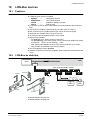
12.1
Features
Double-sized (240x128 dots), backlit LC-Display for most intuitive and userfriendly operation
Context- and system state adjusted operation functions via soft keys
Functionally grouped, ergonomically operating and indicating elements
Detailed event information like event type and location, intervention instruction
texts, system operating conditions etc.
Integrated emergency operation function
Insertable inscription strips in various languages
Access to system functions via four different operating levels depending on user
profile
Configurable for single or multi AREA operation
Access authorisation via password or key switch
Options
– Lockable Plexiglas door H26T030
– RS232 module E3I020
– LON interface E3I040 for LON devices (floor control terminals etc.)
– Parallel indicator panel B3R051
12.2
Options
12.2.1
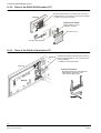
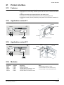
Plexiglas door to B3Q700 (FC/FT)
Z3S200
for the locking of doors and/or
access authorization for operation
H26T030
Plexiglas door
27
Siemens Building Technologies
Fire & Security Products
007836_a_en_--.doc
03.2004
Control terminal B3Q700 (FC/FT)
12.2.2 Place of the E3I020 RS232 module (FT)
RS232 module E3I020 is mounted at the rear of the
control terminal ‘FT’ by means of accessories Z1B020
-> Details see document 007827
B3Q700
Supplied with Z1B020:
Plug-in terminal 12 cont.
Installation material
Protective cover
Use flat cable F20A020
12.2.3 Place of the E3I040 LON interface (FT)
H28G200
LON interface E3I040 connected at the I-Bus of a
remote control terminal 'FT', only mounted in the
housing H28G200
-> Details see document 007827
H28T110
Supplied with Z1B070:
- Mounting bracket with card holder and
terminal block numbering in red
- I-Bus flat and supply cable
B3Q700
28
Siemens Building Technologies
Fire & Security Products
007836_a_en_--.doc
03.2004
Control terminal B3Q700 (FC/FT)
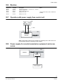
12.3
Installation possibilities (FT)
Built into H23/H26 cabinets
Dimensions
H23 cabinet
B = 125
H = 219
T = 76
Built into H28 cabinet
H23G230
H26G220
Dimensions
H26 cabinet
B = 366
H = 219
T = 76
Dimensions
B = 520
H = 300
T = 70
H28T110
H28G200
By choice
B3R051
H23B020
H23B020+E3I040
B3R051
B3Q700
B3Q700
Built into 19“ cabinet
H28T120
19“ cabinet
G2A130
4xB3R051
B3Q700
G2A140
By choice
B3R051
H23B020
12.4
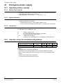
Block diagram
Basic equipment
Option
FC, FT, FG
FC/FT
Mains
C-Bus
B2F020
E3C011
Batteries
AX12..
separately connected
parallel indicator
LON-Bus
Activation of Mimic Display, see chapter
'Mimic Display panel outputs'
E3I040
Parallel branching permissible
I-Bus
24V Supply line
E3I020
RS232
1
2
Databus
F12A100
B3R051
B3R051
F12A100
max.
1000m
B3R051
B3R051
F12A100/470
Printer
– B3R051
– Can be installed separately, however at max. 1000m
– Max. 24 units, however max. 8 addresses
– Free allocation of the LEDs (programming according to application)
– Line and equipment not monitored
29
Siemens Building Technologies
Fire & Security Products
007836_a_en_--.doc
03.2004
Control terminal B3Q700 (FC/FT)
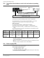
12.5
Connection lines between control unit and external operating
units
Control terminal FT700A
Options
Control terminal
FT700A
B3R051 (Parallel indicator panel)
E3I040 (LON module)
Printer
2…11
leads
Loop C-Bus
max. 1000m per loop with ∅0,6mm G51 (incl. return line)
max. 1400m per loop with ∅0,8mm G51 (incl. return line)
Control unit FC700A
When planning a system the following condition must be complied with:
At least one operating unit must comply with standard EN54, i.e. it must be
equipped with emergency operation and emergency power supply.
EN54 requirements:
Communication as loop line -> design C-Bus as a loop line
Operating units also with emergency operation -> 3 additional wires
Second de-coupled 24V supply -> 3 additional wires or autonomous power
supply
The number of wires in the connection cable depends on the application and the
distances between the stations:
Application
24V supply from
control unit
EN54 complied with
24V supply from
control unit without
emergency operation
and emergency
power supply
C-Bus
24V supply
Emergency power
supply
Emergency operation circuit
Number of wires
✔
(2 wires)
✔
(3 wires)
✔
(3 wires)
✔
(3 wires)
11
✔
(2 wires)
✔
(3 wires)
5
Note:
– Emergency operation circuit required including between CPUs or for a separately connected Gateway
– Emergency operation circuit and emergency supply are not designed as a loop
line
– Emergency supply via separate cable or C-Bus feedback
12.6
Power supply (24V)
Operating unit B3Q700 is designed for the voltage range 18...45VDC
The maximum current at 24V is 400mA
Max. Length of line (approximate):
– For cables ø 0.8mm -> 180m
2
– For cable cross-section 1mm -> 360m
The current consumption for the options (parallel indicator panel, LON-module)
must be taken into account separately
30
Siemens Building Technologies
Fire & Security Products
007836_a_en_--.doc
03.2004
Control terminal B3Q700 (FC/FT)
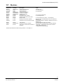
12.7
Modules
Component
B3Q700
CTY00760
CIY00760
FCA725
FCA775
FCA785
H26T030
Z3S200
B3R051
E3I020
Z1B020
Order-No.
A5Q00004719
(OSS)
(OSS)
A5Q00004833
A5Q00004834
A5Q00004835
570530
570349
490513
460239
475907
Description
Control terminal FT700A
Flash program file
Flash program file
Inscription set 'Spanish'
Inscription set 'Italian'
Inscription set 'polish'
Plexiglas door
Key switch module (KABA)
Parallel indicator panel '2x24 LEDs'
RS232 module
Mounting accessories for E3I020
F20A020
476317
Flat cable micro 20 conductors 0.165m
E3I040
Z1B070
Z3I481
499310
A5Q00001720
491185
LON interface
Mounting accessory for E3I040
Cable set for control terminal FT700A in
H28G200
Notes
Operating unit
For control terminal
For control unit
Incl. mounting accessories
For operating access
For the connection of a printer -> see chapter 21
Essential when mounting E3I020 on the rear terminal of
B3Q700 (FT)
Link between E3I020 -> B3Q700, if E3I020 on the rear of
B3Q700 (FT)
Converter between I-Bus and LON-Bus
Essential when mounting E3I040 in housing H28G200
Comprising -> Terminal block with made-to measure
cable, cleat and cable clips
-> Details see document 007827
Cabinets H23/H26/H28 for details referring cabinets -> see chapter 13
31
Siemens Building Technologies
Fire & Security Products
007836_a_en_--.doc
03.2004
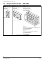
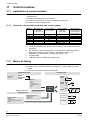
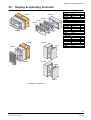
Range of cabinets H23 / H26 / H28
13
Range of cabinets H23 / H26 / H28
H23G230
Dimensions 125x219x76mm
Material Plastic
Colour Pantone 421 grey
Protection category IP40
H26G220
Dimensions 366x219x76mm
Material Plastic
Colour Pantone 421 grey
Protection category IP40
H28G200
Housing with lock (DOM)
Dimensions 520x300x70mm
Material Steel sheet
Colour housing RAL7035 light grey
Protection category IP30
H28G200
Front can not be pivoted
Front can not be pivoted
H28T110
H28T120
H28T110
Door with cut-out for control terminal and parallel indicator panel
B3R051 or cover plate H23B020
Colour door RAL7035 dark grey
Protection category IP30
H28T120
Door with cut-out for 4 parallel indicator panel B3R051
Colour door RAL7035 dark grey
Protection category IP30
Doors are hinged at left!
Details of the cabinets -> see document 007827
32
Siemens Building Technologies
Fire & Security Products
007836_a_en_--.doc
03.2004
Range of cabinets H23 / H26 / H28
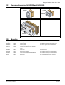
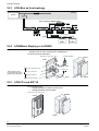
13.1
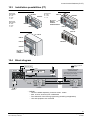
Recessed mounting H23G230 and H28G200
H23U230
H23U220
H23G230
H23G230
H23Z230
H23Z230
UPR28
H28Z010
H28G200
Details of the cabinets -> see document 007827
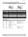
13.2
Modules
Component
H23G230
H26G220
H28G200
H28T110
H28T120
Order-No.
475091
462800
409944
474982
474995
H23B020
H28Z010
H23U220
H23U230
H23Z230
UPR28
476278
410593
379126
532879
532882
430434
Description
Plastic cabinet
Plastic cabinet
Cabinet (without door)
Cabinet door for B3Q700 (FT) / B3R051
Cabinet door for 4 B3R051 Parallel indicator
panel
Cover plate
UP frame set
Recess box to B3R051
Recess box to B3Q580/590/595
Cover frame to B3Q580/590/595/B3R051
Recess box
Notes
For additional indicators and operating units
For remote control terminal B3Q700 (FT)
For various applications
For H28T110/120
For recessed mounting of cabinet H28G200
For recessed mounting of cabinet H23G230
For recessed mounting of cabinet H23G230
For recessed mounting of cabinet H23G230
For 1 H28G200 cabinet (poss. required)
33
Siemens Building Technologies
Fire & Security Products
007836_a_en_--.doc
03.2004
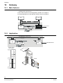
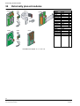
19” accessories
14
19” accessories
Application of 3rd party cabinets
G2A130
G2A140
19”
Z2G030
6HU
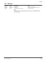
14.1
Modules
Component
Z2G030
G2A130
G2A140
Order-No.
378198
475088
484228
Description
Hinge 19"/6HE
Adapter plate 19"/6HE
Adapter plate 19"/6HE
Notes
Consisting of hinge and spacer profile
For control terminal B3Q700 (FT)
For parallel indicator panel B3R051
34
Siemens Building Technologies
Fire & Security Products
007836_a_en_--.doc
03.2004
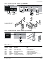
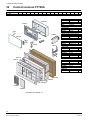
Line modules
15
Line modules
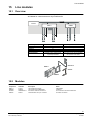
15.1
Overview
E3M111 for addressable detectors SynoLOOP
E3M080 for collective detectors SynoLINE600/-Ex
I-Bus
FC700A
E3M080
Detector system
Number of lines
Number of addresses
Loop line
Stub line
Short-circuit separator
Special features
24V
24V
max. 500mA
max. 500mA
E3M111
SynoLOOP
4
4 x 128
✔
✔
In each device
Separate supply output 24V for
input/output modules
1
2.........
8
SynoLINE600/-Ex
8
8
✔
Line short circuit can be evaluated
as a fault or as an alarm
Z3I1050 or
E3M111
Z1K030
E3M080
15.2
Modules
Component
E3M111
E3M080
Z3I1050
Z1K030
Order-No.
511531
460268
A5Q00004717
484231
Description
Line module SynoLOOP
Line module SynoLINE600/-Ex
Connection cable 19 conductors
Terminal block with p.c.b. Chassis
Notes
Addressable
Collective
For connection via terminal block 'X2'
For direct connection
35
Siemens Building Technologies
Fire & Security Products
007836_a_en_--.doc
03.2004
Line modules
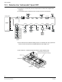
15.3
Detection line "addressable" SynoLOOP
Number of addresses per line max. 128 with APMK1
All detectors, manual call points and input/output modules with integrated line
separator
Connectable types of detectors and connection see document 007831
AI340
AI300
4 Loop lines
DF1191/92
1
DBZ1197A
OH320A
HI32xA
OP620A
DM1133/MT320A
EB322A
OP320A
2
E3M111
DC1192
CB320A
DC1192
DC1192
DC1192
ABI322A
AB322A
3
24VDC
OH320C
24VDC
24VDC
24VDC
SB3
4
OP620C
HI32xC
DM1103
24VDC
OP320C
DT1101-Ex
SynoLINE300
conventional
max. 32
DLO1191
HI62xC
DO1101-Ex
SynoLINE600
collective
max. 25
BFST
DLR11 . .
DF1101-Ex
SynoLINE600-Ex
collective
max. 25
Some detectors have different loading factors, to evaluate how many special detectors can be connected to one addressable line see chapter 16.3
Control output for 1 external response indicator in each detector base
fixed allocation (output active as
soon as the internal LED is flashing)
Room 101
Room 102
ZONE 7
ZONE 5
Room 103
Room 104
36
Siemens Building Technologies
Fire & Security Products
007836_a_en_--.doc
03.2004
Line modules
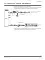
15.4
Detection line "collective" SynoLINE600/-Ex
All detectors on a line have the same collective address (ZONE)
Number of detectors per line max. 25 with KMK1
Line termination depending on application by means of Transzorb or EOL22 (Ex)
Connectable types of detectors and connection see document 007831
8 Stub lines
DLO1191
1
DF1191/92
Line termination: Transzorb 20V/EOL22
Line resistance: max.150Ω
DBZ1197A
HI62xC
DM1103
OP620C
SynoLINE600
2
3
DLR11 . .
E3M080
SynoLINE600-Ex
DM1103
DC1192
8
OP620C
HI62xC
24VDC
DO1101A-Ex
DT1101xA-Ex
DF1101-Ex
Line termination
EOL22 (Ex)
SB3
Some detectors have different loading factors, to evaluate how many special detectors can be connected to one collective line see chapter 16.2.
37
Siemens Building Technologies
Fire & Security Products
007836_a_en_--.doc
03.2004
Connection factors, line resistances and capacitances
16
Connection factors, line resistances and capacitances
16.1
Terminology and abbreviations
KLK
KMK
APLK
APMK
16.2
Collective line factor (SynoLINE600)
Load factor for collective / conventional elements (SynoLINE600/300)
addressable line factor (SynoLOOP)
Load factor for addressable elements (SynoLOOP)
Collective detection line
– The modules E3M080 / DC1192 have the collective line factor KLK 25
– Line resistance max. 250Ω, 150Ω depending on evaluation required (line type 1,
11)
– Line capacitance max. 4µF
The entire line from the control unit to the last detector as well as all response
indicator lines must be included when working out capacitance.
Details see document 007831
The total amount of detectors connected to one collective line should not exceed a loading factor of 25
Element
Smoke detector
Heat detector
Multisensor smoke detector
Smoke detector
Heat detector
Infrared flame detector
Infrared flame detector
Linear smoke detector
Manual call point
In-/output module
16.3
Short designation
OP620C/OP320C
HI620C/622C/HI320C/322C
OH320C
DO1101-Ex
DT1101-Ex
DF1101-Ex
DF1191/92
DLO1191
DM1101, DM1103
DC1192
Load factor KMK
1
1
1
1,6
1
6
6
25
1
1
Addressable detection line
– The line module E3M111 has the addressable line factor APLK 128
– Line resistance see chapter 16.4
– Line capacitance see chapter 16.4
For a description of the E3M111 line module, see document 007831 'Hardware description'.
The total amount of detectors connected to one addressable line should not
exceed a loading factor of 128
Element
Smoke detector
Heat detector
Multisensor smoke detector
Infrared flame detector
Manual call point
Input module
Output module
In-/output module
In-/output module
Short designation
OP620A, OP320A
HI620A/622A, HI320A/322A
OH620A, OH320A
DF1191/92
MT320A, DM1133
EB322A
AB322A
ABI322A
DC1192, CB320A
Load factor APMK
1
1
1
5
1
1
2
2
3
Do not install lines longer than 2000m
38
Siemens Building Technologies
Fire & Security Products
007836_a_en_--.doc
03.2004
Connection factors, line resistances and capacitances
16.4
Line resistance and capacitance
– The max. line resistance of the entire detector loop respectively from the detec-
tor furthest away to each of the two control unit connections must not exceed
150Ω .
– The entire line from the control unit to the equipment connected and back again
to the control unit as well as response indicator lines must be included when
working out capacitance.
max. C
EB322A
max. R
E3M111
DC1192
24VDC
CB320A
DC1192
DC1192
24VDC
24VDC
DC1192
ABI322A
AB322A
24VDC
Max. Resistance 150Ω (max. R)
Max. Capacitance 300nF (max. C) -> max. 600nF with max. 50Ω line resistance
39
Siemens Building Technologies
Fire & Security Products
007836_a_en_--.doc
03.2004
Control modules
17
Control modules
17.1
Application of control modules
Activation of fire control installations (shutting-down ventilation, closing fire
dampers etc.)
Activation and monitoring of alarm device
Activation and monitoring of remote transmission equipment
Activation of Mimic Display panels
17.1.1 Overview of the available modules with control outputs
Modules
E3G070
E3L020
E3G050
E3G060
K3R072
K3G060
K3I110
1
2
Driver outputs
Programmable
2
7 1) 2)
16 1)
Contact outputs
(Volt free)
Programmable
Remote transmission interface
To remote transmission equipment
✔
8
6
5)
48
3)
24 NO contact 4)
16 NO contact 5)6)
Can also be used as control inputs (e.g. 'acknowledgement')
These inputs/outputs also serve for the activation of the remote transmission
equipment
For activation of Mimic Display panel, connected to the operating terminal
B3Q700 or K3I050 (no I-Bus module) -> Details see chapter 17.7
Applicable only with K3R072 -> Details see chapter 17.9
Programmable
LON-Bus module -> Details see chapter 18.5
3
4
5
6
17.2
Monitored control lines
For alarm devices
Means of linking
Any statuses of entry nodes can be linked to control ZONES
Normally, only 1 control ELEMENT is contained in 1 control ZONE (= control
output)
A user text is allocated to each control ZONE
Acquisition level
addressable
collective
Control level
AREA
SECTION
ZONE
E3G050
K3I110
Statuses:
- alarm
- info
- switched off
- on detector TEST
- fault
- etc.
Digital input ‘active’
E3L020
E3G070
Control
ZONE
E3G060
Operating level
Acknowledgement circuit
Visible statuses:
- active
- switched off
- executed ('Acknowledgem.')
- fault
Operatable functions:
- switch on/off
- activate/de
-activate
not
monitored
monitored
40
Siemens Building Technologies
Fire & Security Products
007836_a_en_--.doc
03.2004
Control modules
17.3
Control outputs station type FC700A
Basic equipment
Additional control modules according to application
I-Bus
B3Q700
CPU
E3G070
Driver
1...............7
24V
E3L020
Driver
1..........16
E3I040
Converter
I-Bus/LON
E3G060
Driver
1..........6
1..........8
Z3B171
LON-Bus
30VDC/1A
Z3B171
FÜ
E3G050
250VAC/10A
K3I110
max. 24V/2A
(max. 4A/E3G060)
250VAC/10A
1......16
Fire control
installations
30VDC/1A
Z3I1050
Z1K030
Z3I1050
E3I040
Up to 2 Z3I1050 (with additional
terminal block) can be used otherwise Z1K030 must be used.
E3G070
E3L020
E3G060
E3G050
K3I110
17.4
Control outputs remote station type FT700A
I-Bus
B3Q700
E3I040
converter
I-Bus/LON
E3I040
LON-Bus
K3I110
Z1B070
1......16
K3I110
30VDC/1A
Details mounting E3I040 see document 007827
17.5
Modules
Component
E3G070
E3L020
E3G050
E3G060
K3I110
Z3B171
E3I040
Z1B070
Z3I1050
Z1K030
Order-No.
546661
546645
460255
542539
528812
484383
499310
A5Q00001720
A5Q00004717
484231
Description
Control module 'Universal'
Control module 'Driver'
Control module 'Contacts'
Control module 'Monitored'
LON-I/O card
Relay module 1x 250VAC/10A
LON module
Mounting accessory for E3I040
Connection cable 19 conductors
Terminal block with p.c.b. Chassis
Notes
Included in FC700A-1 package
16 control inputs or outputs
8 control output contacts
6 monitored control lines for alarm equipment
16 programmable in-/outputs
To switch from external voltage
Converter between I-Bus and LON-Bus
Essential for mounting E3I040 in housing H28G200
1 of each per E3L020/E3G050/60
For direct connection
41
Siemens Building Technologies
Fire & Security Products
007836_a_en_--.doc
03.2004
Control modules
17.6
CPU-overlapping controls
all-AREA
single-AREA
FT
FT
FG
Gateway
C-Bus
FC
FC
CPU
A2
A3
A4
FC
CPU
CPU
CPU
2
3
n
1
A1
FC
A5
A6
A7
A8
A9
A10
A11
A12
A..
A..
A..
A..
= AREA
initiating data point
control ZONE/ELEMENT
must be within the same CPU
control device
Limitation: see chapter 8
42
Siemens Building Technologies
Fire & Security Products
007836_a_en_--.doc
03.2004
Control modules
Mimic Display panel outputs
24V
F12A100
or
F12A470
B3Q700 (FT)
K3R072
17.7
LED flat cable F50F410
1
cable length 1m, 24 red LEDs
48
LED flat cable F50F410
Mimic Display panel
24V
Z3I530
(Adapter)
B3Q700 (FC/FT)
Data bus
max.1000m
(not monitored)
K3R072
Parallel branching permissible
LED flat cable F50F410
1
cable length 1m, 24 red LEDs
48
LED flat cable F50F410
Mimic Display panel
Details see document 007831
K3R072:
– Short circuit-protected outputs
– Output for local buzzer and LED operation
– Inputs for button 'buzzer switch-off' und 'lamp test'
– Only suitable for the activation of LEDs
– Outputs can only be allocated the statuses from one logical node
– Max. 24 devices however max. 8 addresses
Synoptic display
panel housing
Short-circuit proof in-/outputs
only for inside housing application
B3Q700
max. permissible length
of the data bus 1000m
LED 1....24
wires 49+50 for 'LED operation'
LED 25....48
wires 49+50 unused
K3R072
K3R072
Z3I520
17.8
Key 'Switch-off buzzer'
Key 'Lamp test'
Buzzer
These in-/outputs can be in
parallel with other K3R072
if located in same cabinet
Modules
Component
K3R072
Z3I520
F50F410
Z3I530
F12A100
F12A470
Order-No.
528605
484969
529141
484972
495275
495288
Description
Mimic Display activation
Cable set for K3R072
LED flat cable for K3R072
Adapter
Flat cable Micro 12-pin, 0.4m
Flat cable Micro 12-pin, 1.5m
Notes
Comprises 12 cables (2-wire with connector, length=0.5m)
50-wire, 24 red LEDs, cable length 1m
To adapt flat cable to terminals
From B3Q700 (FT) to K3R072/B3R051
From B3Q700 (FT) to K3R072/B3R051
43
Siemens Building Technologies
Fire & Security Products
007836_a_en_--.doc
03.2004
Control modules
17.9
Relay outputs
Flat cable supplied with K3G060
24V
K3R072
max. 24 units,
however max.
8 addresses
Parallel branching permissible
24
24 outputs
max. 30V/1A
1
24
24 outputs
max. 30V/1A
Flat cable supplied with K3G060
+/1)
Z3I530
(Adapter)
Data bus
max.1000m
(not monitored)
K3G060
1
24V
B3Q700 (FC/FT)
1
48
K3G060
B3Q700 (FT)
48
K3G060
F12A100
or
F12A470
K3G060
1
K3R072
max. 24 units,
however max.
8 addresses
1
24
24 outputs
max. 30V/1A
1
24
24 outputs
max. 30V/1A
+/-
1)
1) External potential
(switchable via jumper X1......X24)
K3G060:
– 2 K3G060 can be connected to each K3R072
– 24 volt-free relay-make contact
– Contacts not monitored
– Contacts can be individually connected via jumper to externally supplied V+ or
V- potential
Housing supplied by customer
24 Relay outputs
K3R072
K3G060
24 Relay outputs
K3G060
17.10 Modules
Component
K3G060
Z3I530
Order-No.
528786
484972
Description
Relay card incl. flat cable
Adapter
Notes
Option to K3R072
To adapt flat cable to terminals
44
Siemens Building Technologies
Fire & Security Products
007836_a_en_--.doc
03.2004
LON-Bus devices
18
LON-Bus devices
18.1
Features
Activation via local communication Bus 'LON'
4 different types of device available
– B3Q580
=
Text display terminal
– B3Q590/595 =
Text control terminal
– K3I050
=
LON/Mimic Display converter
– K3I110
=
LON I/O card
Connection via I-Bus/LON module E3I040 (converter between I-Bus and LONBus)
The function 'LON-Bus' is possible once per station type 'FC' and 'FT'
Max. 32 devices per LON-Bus (device type can be mixed as required)
Monitored two-wire-Bus without loop line function
All devices require a separate feed line from E3I040
Wiring of the LON-Bus
– As 'stub line' up to 1000m (without T-branches)
– As 'free topology' up to 500m (length of line to all devices added) with 'MICC'
as 'stub line'.... 700m / as 'free topology'... 300m
– With special cable (Belden 85102 or 8471) and as 'stub line' up to 2700m
– Only possible via twisted line (10 turns per meter)
CPU-overlapping functions possible
B3Q59x: bottom three LEDs are pluggable. Allows application with different LED
colour
18.2
LON-Bus as stub line
FC/FT
I-Bus
B3Q700
E3I040
max. length of LON-Bus 1000m
LON-Bus
Z1K030
24VDC
K3I110
Z3I1050
K3I050
24VDC
E3I040
B3Q590/
595
B3Q580
Data bus
(not monitored)
K3R072
or
B3R051
K3R072
or
B3R051
E3I040
Z1B070
Details K3R072 see page 43
Details B3R051 see page 29
45
Siemens Building Technologies
Fire & Security Products
007836_a_en_--.doc
03.2004
LON-Bus devices
18.3
LON-Bus as free topology
FC/FT
I-Bus
B3Q700
E3I040
max. length of LON-Bus 500m
B3Q580
LON-Bus
24VDC
K3I110
K3I050
24VDC
B3Q590/
595
B3Q580
Data bus
(not monitored)
K3R072
or
B3R051
18.4
K3R072
or
B3R051
LON/Mimic Display p.c.b K3I050
Allows connection of Mimic Display p.c.b. K3R072 or parallel indicator panels
B3R051 (max.24 units, however max. 8 addresses)
Various local inputs/outputs
Dimensions: 106 x 200 x 14mm
to K3R072/B3R051
H23G230
K3I050
Z3I530
Input key 'buzzer switch-off'
Lon-Bus 24V
The functions of the
in-/outputs refer on the
K3R072 resp. B3R051
Input key 'lamp test'
Output local buzzer
50cm
Z3I520
Output LED 'operation'
18.5
K3I050
Z3B230
LON I/O card K3I110
Input/output card
– 16 programmable monitored control inputs
– 16 programmable control outputs
Dimensions: 122 x 220 x 14mm
H23G230
K3I110
K3I110
46
Siemens Building Technologies
Fire & Security Products
007836_a_en_--.doc
03.2004
LON-Bus devices
18.6
Indicator devices B3Q580 and B3Q590/595
Both devices have identical dimensions
Recessed mounting see page 33
H23G230
H23G230
B3Q580
Function
LCD 2x40 characters backlight
yellow
Alarm event indicator
Fault event indicator
Selectable operating mode
Buzzer, can be silenced
3 programmable LEDs
Function key ’Onward switching’
Function key ’Acknowledge’ /
’Reset’
Key switch for operating access
For installation in housing
H23G230
Slide–in inscription strips
Operating voltage
Current consumption at 24V
18.7
B3Q590 (Nordic lock)
B3Q595 (KABA lock)
B3Q580 Text display terminal
B3Q590/595 Text control terminal
✔
✔
All ZONES from 1...4 selectable SECTIONS
Selectable (yes/no via SWE700A)
14 (selectable via SWE700A)
✔
✔ (also serves to silence buzzer + lamp test)
All ZONES per station (not selectable)
Selectable (yes/no via SWE700A)
14 (selectable via SWE700A)
✔
✔
✔ (also serves to silence buzzer + lamp test)
✔
B3Q590 = Nordic
B3Q595 = KABA
✔
✔
✔
9...45VDC
Quiescent: 20mA / max: 180mA
✔
9...45VDC
Quiescent: 18mA / max: 185mA
Modules
Component
E3I040
Z3I1050
Z1K030
K3I050
Order-No.
499310
A5Q00004717
484231
496766
Description
LON module
Connection cable 19 conductors
Terminal block with p.c.b. chassis
LON/Mimic Display converter
K3I110
B3Q580
B3Q590
528854
496177
496180
B3Q595
534110
H23G230
Z3I520
475091
484969
LON I/O card
Floor repeater panel
Floor repeater panel with control functions with
Nordic lock
Floor repeater panel with control functions with
KABA lock
Plastic housing
Cable set to K3R072
Z3I530
Z3B230
Z1B070
484972
559001
A5Q00001720
Adapter
Support plate-set
Mounting accessory for E3I040
Notes
Converter between I-Bus and LON-Bus
For connection via terminal block 'X2'
For direct connection
Interface between LON-Bus and Data Bus for
K3R072 or B3R051
16 programmable control in-/outputs
Comprises 12 cables (2-wire with connector,
length=0.5m)
To adapt flat cable to terminals
For K3I050 in H23G230
For mounting in housing H28G200
47
Siemens Building Technologies
Fire & Security Products
007836_a_en_--.doc
03.2004
Gateway
19
Gateway
19.1
Main features
Connection C-Bus network <-> Building management system via V28 interface
(RS232) ISO1745 Protocol
Per C-Bus network are several gateway possible, see chapter 8
Install preferably in the fire detection system control unit cabinet
FT
FT
C-BUS
I-BUS
FC
Line-
FG700A
Control-
ISO1745 Protocol
module
Detector
19.2
Application
Fire detection control unit
C-Bus
24VDC
I-BUS
FC
Linemodules
Controlmodules
E3H020
RS232
X2
ISO1745 Protocol
Detector
Module chassis
view modules
28
56
38
E3G070
47
48
E3H020 + 2xZ1K030
46
37
E3M111
E3C011
27
E3C011
E3G070
E3M111
47
Z1K030
57
58
E3H020
48
Siemens Building Technologies
Fire & Security Products
007836_a_en_--.doc
03.2004
Gateway
19.3
Modules
Component
E3H020
CKQ007.60
Z1K030
Order-No.
460475
A5Q00005137
484231
Description
Gateway module
EPROM set
Terminal block with p.c.b. Holder
Notes
Requires 2 module spaces
Software for ISO1745 Protocol for E3H020
For direct connection
Note:
The E3H020 is factory side equipped with 4 RAMs (4x 512Kx8Bit) details see
document 007831
49
Siemens Building Technologies
Fire & Security Products
007836_a_en_--.doc
03.2004
Remote transmission
20
Remote transmission
Most fire detection systems are linked to a remote transmission system. Therefore
in case of alarm (alarm stage 2) the fire detection system must initiate the remote
transmission device (RT-device).
Remote transmission device
– Located in cabinet of control unit
– Required space depends on the type of remote transmission device
– Powered by 24VDC of the fire control unit
– Single channel (alarm + fault) or multi channel (several alarm channels)
– Disabling/enabling via B3Q700 (FC/FT)
Interfacing
– Via output contacts and special control in-/outputs of the E3G070
Interfacing via E3G070
FC700A
I-Bus
B3Q700 (CPU)
E3G070
K2
alarm
fault
24V
RT-device
50
Siemens Building Technologies
Fire & Security Products
007836_a_en_--.doc
03.2004
Printer interface
21
Printer interface
21.1
Features
Provided with station types FC, FT
Designed for commercially available printer with ISO-Latin1 or EPSON character
set
Always allocated to all existing AREAS for the station used
The printer can be individually switched on/off via operating terminal
The event memory can be printed only if the printer is connected to a station FC
or FT
21.2
Application variant FT
E3I020
B3Q700
FT
B3Q700
ST2
to printer
I-Bus
ST2
F20A020
E3I020
ST1
ST2
RS232
C-Bus
max.1000m
Z1B020
F20A020
in cabinet H26/H28
21.3
Application variant FC
E3I020
FC
B3Q700
F20A140
Z1K030
I-Bus
to printer
ST2
F20A140
ST1
E3I020
X2
B3Q700
RS232
C-Bus
max.1000m
Housing control unit
21.4
Modules
Component
E3I020
Z1B020
F20A020
Z1K030
F20A140
Order-No.
460239
475907
476317
484231
496863
Description
RS232 module
Mounting accessories
Flat cable 'Micro' 20 conductors, 0.165m
Terminal block with p.c.b. Holder
Flat cable 'Micro' 20 conductors, 0.650m
Notes
Level adaptation HCMOS -> RS232
To mount E3I020 at the rear of B3Q700 (FT)
To mount E3I020 on the module space Pos.27
51
Siemens Building Technologies
Fire & Security Products
007836_a_en_--.doc
03.2004
Power supply
22
Power supply
22.1
Concept
The power supply for the FC700A fire detection system consists of:
Converter
(mains voltage -> system voltage 29,6V)
Battery charging unit (by means of E3C011)
Batteries (lead)
(capacity as required)
22.2
Special functions
– Automatic battery load test
– Battery charging characteristic can be programmed according to make
22.3
Application
–
–
–
–
22.4
Determine required battery capacity individually -> see chapter 23
Max. 27Ah per battery charging unit (> 27Ah = auxiliary power supply)
Parallel operation of several battery charging units possible
Battery lead without EMI-protection (battery cannot be mounted separately)
Power supply for the control unit
Battery charging module E3C011 required
Mains
FC
B2F020
40...220VA
E3C011
Batteries
AX12..
TF*
29,6V
B3Q700
22.5
I-Bus
Auxiliary power supply
FT
* TF = Temperature sensor for battery temperature monitoring
Mains
Mains
Basic emergency
power supply
C-Bus
TF*
Batteries
AX12..
Extension
B2F020
B2F020
TF*
Batteries
AX12..
E3C011
Battery charging
unit
24V
E3C011
FC
Monitoring via HW monitoring path
52
Siemens Building Technologies
Fire & Security Products
007836_a_en_--.doc
03.2004
Power supply
22.6
Modules
Component
B2F020
E3C011
Z3I470
AX1201
Order-No.
470588
505479
484341
225487
Description
Converter 115/230VAC -> 29,6VDC 6A (... 220VAC)
Battery charging unit
Cable set with card holder
Battery 12V / 27Ah
AX1210
475570
Battery 12V / 15Ah
22.7
Notes
Capacity based battery make 'ALARMCOM'
(FIAMM)
Operation with power supply from control unit
FT
+ / - /Earth
Output 1
FC
Output 2
24V / 2A
I-Bus
B3Q700
Note: A 2nd supply output is only necessary for operating units, which must comply with EN54 (at least 1 operating unit per system)
22.8
Power supply for remote transmission equipment and accessories
FC
B3Q700
I-Bus
E3G070
24V // 0.63A
24V
0,63A
Remote transmission
or other equipment
53
Siemens Building Technologies
Fire & Security Products
007836_a_en_--.doc
03.2004
Emergency power supply
23
Emergency power supply
23.1
Specifying battery capacity
23.1.1 Battery rated capacity
– The battery rated capacity is based on the discharge over a period of 20 hours
– Faster discharge causes a loss of capacity:
Discharge over 12-hour period:
23.1.2
9% loss (K = 1.1)
Ageing of battery
– With increasing age, the battery suffers a loss of capacity
Allow a safety factor for ageing
(Total quiescent current y 1.25 or battery capacity y 0.8)
> 24h in conformity with DIN VDE 0833, part 2, no safety factor is necessary
23.1.3
Calculation
Battery capacity must be calculated individually!
Formula: Ah = A x h x 1.25 (poss. x K)
Ah
A
h
1.25
K
23.2
= Battery capacity in Ah
= the sum of the quiescent current for all modules
= Required operating period in hours
= Safety factor for ageing
= Capacity loss if discharge is over considerably less than 20 hours
Capacity values for standard configurations
Configuration
128 detectors addressable
16 collective lines
Quiescent current
7outputs
7 outputs
235mA
315mA
Battery capacity requirement for
12h
24h
72h
3,8Ah
7,0Ah
16,9Ah
5,1Ah
9,4Ah
22,6Ah
Notes:
– Equipped with 1 control terminal B3Q700
– Discharge over a 12-hour period, 9% loss of capacity taken into account
– Factor 1.25 for ageing taken into account at 12h and 24h (72h without safety
factor)
– Without remote transmission equipment
– Only quiescent current taken into account
54
Siemens Building Technologies
Fire & Security Products
007836_a_en_--.doc
03.2004
Emergency power supply
23.3
Quiescent current table
– Quiescent current when on battery operation (24V)
– As basis for individual calculation of emergency power supply
– The current for the 5V supply is included in these values
Module
B2F020
B3Q700
B3Q580
B3Q590/595
B3R051
E3C011
E3G050
E3G060
E3G070
E3H020
E3I020
E3L020
E3L030
E3M080
E3M111
K3G060
K3R072
Quiescent current at 24VDC (typical)
0
100mA LCD backlight ’inactive’ (active = + 200mA)
20mA
18mA
40mA
all LEDs inactive
20mA
10mA
all relays inactive
25mA
all control lines terminated
25mA
control line ’Horn’ terminated
100mA
25mA
22mA
18mA
85mA
37mA + 6mA per terminated line
210mA (=50mA + 0,31mA per D–Bus device) 1)
(without external 24V load)
6mA
40mA
Z3B171
E3I040
K3I050
K3I110
0
15mA
15mA
24mA
without external 24V load
max. 184mA all relay activated incl. service LED
1
Additional current with alarm condition
0
+ 230mA
+ 160mA
+ 167mA
+ 2mA
per activated LED
0
+ 11mA per activated relay
+ 23mA per activated control line, without external load
+ 34mA without external load (horns etc.)
0
0
+ ..mA depends from the activated device
+ 40mA without external load (FBF, HM, FSK)
+ 10mA per line in alarm
0
+ 3mA
+ 2mA
0
+ 27mA
0
+ 0mA
+ 10mA
+ 0,5mA
per relay
per activated LED
per activated relay
per activated relay
or 4mA per activated LED
per activated relay
per input with closed contact
Only valid for device with APMK = 1 (multiply value for devices > 1)
55
Siemens Building Technologies
Fire & Security Products
007836_a_en_--.doc
03.2004
Alarm concept
24
Alarm concept
The alarm concept must be worked out individually for each system
The important thing is to pass on the alarm message quickly to the appropriate
group of recipients
The requirements vary between
– 'Discreet alerting' of the reconnaissance squad, e.g. via staff paging system
– 'Alarm / evacuation' for people familiar with the location
– 'Alarm / evacuation' for people unfamiliar with the location
– 'Area evacuation', e.g. building storey
24.1
Cerberus Alarm Concept (CAC)
The Cerberus alarm concept prevents the unnecessary turnout of the fire department for minor incidents
The CAC is based on an alarm organization involving the presence or absence
of personnel:
– Presence of operating personnel or "Day"
– Absence of operating personnel or "Night"
The response of the operating personnel is monitored by two independent time
circuits (V1 and V2) monitored
The CAC is an integrated part of the FC700A control unit. The required parameters can be entered via the user functions
24.2
Principle of the Cerberus alarm concept
– During the "Day" operating mode, if an alarm is activated its source is located
and the decision is taken "Emergency" or "Minor incident"
– During "Night" operating mode, all signals immediately generate a "Remote
alarm"
– The activation of a manual call point always immediately generates a "Remote
alarm"
Alarm
event
manned or
unmanned
unmanned
Operating mode
manned
F
Local
alarm
V1
running
V1 = 0
<Acknowledge>
pressed
'Emergency'
'Minor incident'
<Alarm delay OFF>
- or F
pressed
V2
<Reset> pressed
running
V2 = 0
General
alarm
Remote
alarm
Normal
operation
56
Siemens Building Technologies
Fire & Security Products
007836_a_en_--.doc
03.2004
Alarm concept
24.3
Determine the alarm organization
– The FC700A fire detection system has up to 64 programmable organization lev–
–
–
–
–
24.4
els (AREAS)
A number of "Alarm variants" are possible (can be selected per ZONE)
The time countdown memories "V1" and "V2" must be specified individually
The time countdown memory "V2" can be defined per ZONE (if required)
Various special local functions are provided
The alarm organization is programmed individually (via maintenance PC)
Organization of system operation
The place of operation of the fire detection system must be determined from an
organizational point of view
If required a second operating facility must be provided
If operating units are particularly exposed, they must be fitted with a lockable
Plexiglas door (H26T030 + Z3S200)
The type of event and the location are displayed on the operating unit in plain
text
The locations (rooms etc.) are individually defined by means of the "User text"
(via maintenance PC)
If required, an additional event-related instruction, a so-called countermeasures text, can be allocated
The fire detection system may only be operated by instructed personnel (operating access is therefore protected by password or key switch)
Details of control terminal FT700A see chapter 12
57
Siemens Building Technologies
Fire & Security Products
007836_a_en_--.doc
03.2004
Commissioning
25
Commissioning
The FC700A fire detection system is designed for rational systems engineering.
Connection work at the control unit can be due by non-specialist personnel
(e.g. outside electricians). However, co-ordinated supervision is still essential.
Specially trained personnel with a maintenance PC are required for commissioning
(service engineer).
Details see document 007828
58
Siemens Building Technologies
Fire & Security Products
007836_a_en_--.doc
03.2004
Parameterization, Flash programming
26
Parameterization, Flash programming
Parameters are set for the FC700A fire detection system via the maintenance
PC by means of the software tool set 'SWE700A'.
Online-Help text
Flash programming is only relevant if B3Q700 is used as replacement for FC700A
New software is programmed by means of the 'Flash Tool' software. For the
modules B3Q700 the application software is now loaded into the Flash ROM via
the maintenance PC by means of the 'Flash Tool' software.
Details see Online-Help in SWE700A
B3Q700 (FT700A)
- for flash programming new application software
- download all system data
Control terminal
ST2
Modem box
RS232
B3D021
FC
C-Bus
ST2
Maintenance PC with
'SWE700A' + 'FlashTool'
software
I-Bus
B3Q700 (FC700A)
Control unit
26.1
Functions
–
–
–
–
–
–
26.2
E3M...
Load new application software (Flash) if necessary
Prepare/supplement structure of the system
Define user functions (system-specific)
Specify/correct user text
Detector localization
Data transfer of user functions to control unit
Modules
Component
B3D021
Order-No.
505259
Description
Modem box for SWE700A (DUAL RS232 ITF)
M3C700
505330
A5Q00004798
Flat cable L=0,2m
USB Dongle
Notes
Complete with flat cable 20 conductors,
L=0.2m
As spare part
Key for SWE700A
59
Siemens Building Technologies
Fire & Security Products
007836_a_en_--.doc
03.2004
FC700A modules in alphabetical order
27
FC700A modules in alphabetical order
Component
AX1201
AX1210
B2F020
Order-No.
225487
475570
470588
B3D021
B3Q580
B3Q590
B3Q595
B3Q700
B3R051
CIY00760
CKQ007.60
CTY00760
E3C011
E3G050
E3G060
E3G070
E3H020
E3I020
E3I040
E3L020
E3L030
E3M080
E3M111
F12A100
F12A470
F20A020
505259
496177
496180
534110
A5Q00004719
490513
(OSS)
A5Q00005137
(OSS)
505479
460255
542539
546661
460475
460239
499310
546645
475994
460268
511531
495275
495288
476317
Description
Battery 12V / 27Ah
Battery 12V / 15Ah
Converter 115/230VAC -> 29,6VDC 6A
(...220VAC)
Modem box for SWE700A (DUAL RS232 ITF)
Floor repeater panel
Floor repeater panel with control functions
Floor repeater panel with control functions
Control terminal FT700A
Parallel indicator panel '2x24 LEDs'
Flash program file
EPROM set
Flash program file
Battery charging unit
Control module 'Contacts'
Control module 'monitored'
Control module 'universal'
Gateway module
RS232 module
LON module
Control module 'Driver'
Control module VdS
Line module SynoLINE600/-Ex
Line module SynoLOOP
Flat cable Micro 12-pin, 0.4m
Flat cable Micro 12-pin, 1.5m
Flat cable micro 20 conductors 0.165m
F20A140
F50F410
FC700A-1
496863
529141
A5Q00004734
Flat cable 'Micro' 20 conductors, 0.650m
LED flat cable for K3R072
Control unit pre-assembled
FCA725
FCA775
FCA785
G2A130
G2A140
H23B010
H23B020
H23G230
H23U220
H23U230
H23Z230
H26G220
H26T030
H28G200
H28T110
H28T120
A5Q00004833
A5Q00004834
A5Q00004835
475088
484228
476210
476278
475091
379126
532879
532882
462800
570530
409944
474982
474995
H28Z010
H38G310
K3G060
K3I050
410593
484930
528786
496766
Inscription set 'Spanish'
Inscription set 'Italian'
Inscription set 'polish'
Adapter plate 19"/6HE
Adapter plate 19"/6HE
Cover plate for FC700A
Cover plate
Plastic cabinet
Recess box to B3R051
Recess box to B3Q580/590/595
Cover frame to B3Q580/590/595/B3R051
Plastic cabinet
Plexiglas door
Cabinet (without door)
Cabinet door for B3Q700 / B3R051
Cabinet door for 4 B3R051 parallel indicator
panel
UP frame set
Housing set
Relay card incl. flat cable
LON/Mimic Display converter
K3I110
K3R072
528854
528605
LON I/O card
Mimic Display activation
M3C700
UPR28
Z1B020
A5Q00004798
430434
475907
USB Dongle
Recess box
Mounting accessories for E3I020
Z1B070
Z1K030
Z2G030
Z3B171
Z3B230
Z3I1050
Z3I1060
Z3I380
A5Q00001720
484231
378198
484383
559001
A5Q00004717
A5Q00004722
475567
Mounting accessory for E3I040
Terminal block with p.c.b. holder
Hinge 19"/6HE
Relay module 1x 250VAC/10A
Support plate-set
Connection cable 19 conductors
Terminal block, 2x20 terminals in two levels
Cable set I-Bus long
Notes
Capacity based battery make 'ALARMCOM' (FIAMM)
Complete with flat cable 20 conductors, L=0.2m
With Nordic lock
With KABA lock
Operating unit
For control unit
Software for ISO1745 Protocol for E3H020
For control terminal
8 control output contacts
6 monitored control lines for alarm equipment
Included in FC700A-1 package
Requires 2 module spaces
For the connection of a printer
Converter between I-Bus and LON-Bus
16 control inputs or outputs
For collective detectors
For addressable detectors
From B3Q700 (FT) to K3R072/B3R051
From B3Q700 (FT) to K3R072/B3R051
Link between E3I020 -> B3Q700, if E3I020 on the
rear of B3Q700 (FT)
50-wire, 24 red LEDs, cable length 1m
Including B3Q700, H23B010, B2F020, E3C011,
Z3I470, E3G070, Z3I380, 2x Z3I1050, 1x Z3I1060
pre-wired
For control terminal B3Q700 (FT)
For parallel indicator panel B3R051
As spare part
For H28T110
For additional indicators and operating units
For recessed mounting of cabinet H23G230
For recessed mounting of cabinet H23G230
For recessed mounting of cabinet H23G230
For remote control terminal B3Q700 (FT)
Incl. mounting accessories
For various applications
For recessed mounting of cabinet H28G200
Door without cut-out
Option to K3R072
Interface between LON-Bus and Data Bus for K3R072
or B3R051
16 programmable control in-/outputs
Comprises 12 cables (2-wire with connector,
length=0.5m)
Key for SWE700A
For 1 H28G200 cabinet (poss. required)
Essential when mounting E3I020 on the rear terminal
of B3Q700 (FT)
Essential when mounting E3I040 in housing H28G200
Consisting of hinge and spacer profile
To switch from external voltage
For K3I050 in H23G230
With terminal block and p.c.b. Holder
For additional modules
To connect modules at the bottom with modules at the
60
Siemens Building Technologies
Fire & Security Products
007836_a_en_--.doc
03.2004
FC700A modules in alphabetical order
Component
Order-No.
Description
Z3I470
Z3I481
484341
491185
Z3I520
484969
Cable set with card holder
Cable set for control terminal FT700A in
H28G200
Cable set for K3R072
Z3I530
Z3S200
484972
570349
Adapter
Key switch module (KABA)
Notes
top
Comprising -> Terminal block with made-to measure
cable, cleat and cable clips
Comprises 12 cables (2-wire with connector,
length=0.5m)
To adapt flat cable to terminals
For operating access
61
Siemens Building Technologies
Fire & Security Products
007836_a_en_--.doc
03.2004
Spare parts
28
Spare parts
Component
EOL22
KABA100
-
Order-No.
505739
463686
462790
463809
564669
516222
505330
471451
467478
145635
145606
145648
450388
145680
467177
450391
424246
450414
338879
145729
433363
163837
484396
459729
475774
475237
495440
483669
463977
483672
463951
463964
460051
319351
505330
Description
Buzzer 12-36V 3500Hz 85DB
Card holder
Cover frame (plastic)
Cover frame (plastic)
Duplicate key DOM at locking 2C 2500
End of line element
Flat cable L=0,2m
Flat cable I-Bus + supply cable 'short'
Flat cable micro 20 conductors, 0.17m
Fuse 0.25A slow blow
Fuse 0.4A slow blow
Fuse 0.5A slow blow
Fuse 0.5A slow blow, with high breaking capacity
Fuse 0.63A slow blow
Fuse 0.8A slow blow, with high breaking capacity
Fuse 1.0A slow blow, with high breaking capacity
Fuse 1.25A quick acting
Fuse 2.0A slow blow, with high breaking capacity
Fuse 5A slow blow
Fuse 6.3A slow blow
Fuse 6.3A slow blow, with high breaking capacity
Key 'KABA 8' (#100)
Key 'Nordic'
Lithium battery 3V, to solder
PTC, 2kΩ, 0.5%, with cable
Terminal block, pluggable, 12 cont., orange
Terminal block, pluggable, 3 cont., orange
Terminal block, pluggable, 4 cont., grey
Terminal block, pluggable, 4 cont., orange
Terminal block, pluggable, 4 cont., black
Terminal block, pluggable, 5 cont., orange
Terminal block, pluggable, 6 cont., orange
Transzorb diode bidirectional 20V, 5%, 600W/ms
Zero-Ohm resistor
Flat cable L=0,2m
Notes
for B3Q700
for Z1K030/Z3I1050
for B3Q700
for B3R051/B3Q580/590/595
for H28G200
for B3D021
for I-Bus modules
for E3I020
for E3G070
for B3R051, K3R072, K3G060
for E3G050
for B3Q700, E3L020
for E3G070
for B3Q700, E3H020
for E3M111
for E3L020
for E3H020, E3L030, E3G060/70
for E3G070
for E3G060
for E3C011
for B3Q595
for B3Q590
for B3Q700
for E3C011
for E3I020
for E3H020
for B3Q700 (C-Bus)
for all I-Bus modules (K1)
for B3Q700 (power supply monitoring)
for B3Q700 (emergency operation)
for B3Q700, B3R051, K3R072, E3G070
for E3M080
for various modules (jumper)
for B3D021
62
Siemens Building Technologies
Fire & Security Products
007836_a_en_--.doc
03.2004
Configuration sheets
29
Configuration sheets
The following pages can be copied or used as a basis for individual local requirements.
The configuration for specific systems is entered on these pages (location of units,
number and type of modules, etc.).
29.1
List of configuration sheets
FC700A
– Configuration with control terminal B3Q700 as main CPU (control unit)
Details see page 64
Auxiliary power supply
Details see page 65
FT700A
– Configuration for control terminal B3Q700
Details see page 66
B3Q580/590/595, B3R051
– Configuration display & operating terminals
Details see page 67
K3I110, K3I050, K3R072, K3G060 etc.
– Externally placed modules
Details see page 68
63
Siemens Building Technologies
Fire & Security Products
007836_a_en_--.doc
03.2004
Control unit FC700A
30
Control unit FC700A
Type of detection line
Number of detector addresses
Number of lines
SynoLOOP
SynoLINE600/-Ex
Fire control installations
Number of control outputs
for 30V
for 250V
FC700A-1
Control unit
FC700A-1
A5Q00004734
23
B2F020
Mains
terminals
AC/DC converter
21
Inscription sets
FCA…
A5Q0000….
max. 10x
Z3B171
31
AX1201
or
B
A
AX1210
or
..............
51
AX1201
or
AX1210
Control unit FC700A including:
E3C011, E3G070, E3M111,
40 Terminals, B2F020
pre-wired
or
..............
View A
28
EMC Precaution:
Slot rows with E3C011
module must not be fit
with either E3I040 module
E3C011
Z3I470
27
View B
38
46
47
48
56
57
58
Terminalblock
X1
40 Terminals
E3M111
Z1K030
E3G070
Z1K030
37
Modules
E3M111
511531
E3M080
460268
E3L020
546645
E3G050
460255
E3G060
542539
E3I020
460239
E3I040
499310
E3H020 *
546658
E3L030 *
475994
* requires 2 module spaces
Cable, terminals, relay
Z1K030
484231
Z3I1050
A5Q00004717
Z3I1060
A5Q00004722
Z3I380
475567
Z3B171
484383
Batteries
AX1201
AX1210
225487
475570
EPROM to E3H020
CKQ007.60 A5Q00005137
X2
Details see chapter 10
64
Siemens Building Technologies
Fire & Security Products
007836_a_en_--.doc
03.2004
Auxiliary power supply
31
Auxiliary power supply
Housing
H38G310
H38G310
23
Mains
terminals
Power supply
B2F020
470588
E3C011
505479
31
AX1201
or
484930
A
AX1210
or
..............
Cable set
Z3I470
484341
Batteries
AX1201
AX1210
225487
475570
51
AX1201
or
AX1210
or
..............
37
38
B2F020
28
E3C011
Z3I470
27
46
47
48
56
57
58
AC/DC converter
View A
Details see chapter 11
65
Siemens Building Technologies
Fire & Security Products
007836_a_en_--.doc
03.2004
Control terminal FT700A
32
Control terminal FT700A
No.
FT700A
1
2
3
4
5
6
7
8
9
10
11
12
13
14
15
16
Control terminal 'FT'
B3Q700
A5Q00004719
H26G220
Inscription sets
FCA…
A5Q0000….
B3Q700
Accessories
H26T030
570530
Z3S200
570349
Z1B020
H26T030
FCA...
RS232 interface & accessories
E3I020
460239
Z1B020
475907
F20A020
476317
LON interface & accessories
E3I040
499310
Z1B070
A5Q0001720
Z3S200
Z1B070
Cabinet H26
H26G220
462800
Cabinet H28
H28G200
H28T110
H28Z010
UPR28
H28T110
H28T120
409944
474982
410593
430434
Additional equipment
B3R051
490513
Cover plate
H23B020
476278
Cable set
Z3I481
491185
UPR28
H28Z010
H28G200
B3R051
H23B020
Details see chapter 12
66
Siemens Building Technologies
Fire & Security Products
007836_a_en_--.doc
03.2004
Display & operating terminals
33
Display & operating terminals
H23U230
Floor panels
B3Q580
496177
B3Q590
496180
B3Q595
534110
H23G230
B3Q590
Cabinet
H23G230
B3Q595
B3Q580
475091
Accessories for recess mounting
H23Z230
532882
H23U230
532879
H23U220
379126
H23G230
H23Z230
LON/Mimic display converter
K3I050
496766
LON I/O card
K3I110
528812
H23U220
Support plate
Z3B230
559001
H23G230
K3I110
H23Z230
H23G230
Additional equipment
B3R051
490513
H23G230
K3I050
B3R051
Z3B230
Details see chapter 18
67
Siemens Building Technologies
Fire & Security Products
007836_a_en_--.doc
03.2004
Externally placed modules
34
K3R072
Externally placed modules
Z3I530
F50F410
K3G060
F12A...
Z3I520
Mimic & accessories
K3R072
528605
Z3I520
484969
Z3I530
484972
Relay card
K3G060
528786
Flat cable, LED flat cable
F12A100
495275
F12A470
495288
F50F410
529141
LON/Mimic display converter
K3I050
496766
K3I050
Z3I530
K3I110
LON I/O card
K3I110
528812
Z3I520
Details see chapter 17.7 / 17.9 / 18
68
Siemens Building Technologies
Fire & Security Products
007836_a_en_--.doc
03.2004
Siemens Building Technologies AG
Alte Landstr. 411
CH-8708 Männedorf
Tel. +41 1 - 922 6111
Fax +41 1 - 922 6450
www.sibt.com
Document no.
007836_a_en_--
Edition
03.2004
Manual FC700
Section 2