1
INSTRUCTION MANUAL
COM100
Cellular Phone Package
Revision: 9/01
C o p y r i g h t ( c ) 1 9 8 7 - 2 0 0 1
C a m p b e l l S c i e n t i f i c , I n c .
Warranty and Assistance
The COM100 CELLULAR PHONE PACKAGE is warranted by
CAMPBELL SCIENTIFIC, INC. to be free from defects in materials and
workmanship under normal use and service for twelve (12) months from date of
shipment unless specified otherwise. Batteries have no warranty. CAMPBELL
SCIENTIFIC, INC.'s obligation under this warranty is limited to repairing or
replacing (at CAMPBELL SCIENTIFIC, INC.'s option) defective products.
The customer shall assume all costs of removing, reinstalling, and shipping
defective products to CAMPBELL SCIENTIFIC, INC. CAMPBELL
SCIENTIFIC, INC. will return such products by surface carrier prepaid. This
warranty shall not apply to any CAMPBELL SCIENTIFIC, INC. products
which have been subjected to modification, misuse, neglect, accidents of
nature, or shipping damage. This warranty is in lieu of all other warranties,
expressed or implied, including warranties of merchantability or fitness for a
particular purpose. CAMPBELL SCIENTIFIC, INC. is not liable for special,
indirect, incidental, or consequential damages.
Products may not be returned without prior authorization. The following
contact information is for US and International customers residing in countries
served by Campbell Scientific, Inc. directly. Affiliate companies handle repairs
for customers within their territories. Please visit www.campbellsci.com to
determine which Campbell Scientific company serves your country. To obtain
a Returned Materials Authorization (RMA), contact CAMPBELL
SCIENTIFIC, INC., phone (435) 753-2342. After an applications engineer
determines the nature of the problem, an RMA number will be issued. Please
write this number clearly on the outside of the shipping container.
CAMPBELL SCIENTIFIC's shipping address is:
CAMPBELL SCIENTIFIC, INC.
RMA#_____
815 West 1800 North
Logan, Utah 84321-1784
CAMPBELL SCIENTIFIC, INC. does not accept collect calls.
WARNING: The red LED power indicator/switch on the RJ11C interface box is lit when the cellular
transceiver is on. The control line from the datalogger must be used to turn the transceiver off and
on. DO NOT USE THE RED LED POWER BUTTON AS A SWITCH. If the transceiver is manually
switched off while under datalogger control, the datalogger will not be able to turn it on again. Refer
to Section 9.
NOTE: The COM200 or COM210 field phone modem when used with the COM100 Cellular Phone
package supports 300, 1200, 2400, and 4800 baud connections. Campbell Scientific datalogger
serial ports support a 300, 1200, and 9600 baud terminal connection. Additional commands must
be sent to the PC calling modem during the dialing sequence to allow a 2400 and 4800 baud
modem connect speed with the field modem. Check your calling modem manual for support of this
feature. Bandwidth limitations over the Analog Cellular Phone System prevents a reliable modem
connection above 4800 baud.
This is a blank page.
HOW TO GET STARTED:
1. Take the COM100 phone package to your cellular service provider to program the phone and setup
your service agreement. If your service provider has any questions regarding programming of the
phone, have them contact the Motorola Cellular Information Center at 1-800-331-6456.
2. To program your phone your cellular service provider will need:
a. COM100 cellular phone package and ESN described in step 3.
b. Motorola Handset supplied by your Service Provider (Model SCN2504A or equivalent).
c. **Power Control Cable provided by CSI or Motorola Power Cable (Model SKN4302A or equivalent ).
**SEE WARNINGS PAGE 4.
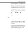
3. The information your service provider will need to program the phone will be the Manufacturer of the
Cellular Phone (i.e., Motorola) and the Electronic Serial Number (ESN). The ESN is located on a
bar-coded label on the back of the cellular phone. The actual location* of the ESN on the label can
be seen in the example below and is shown as bold characters (Example: D57E1504). The ESN
always consists of 8 characters.
LABEL #1
SUN19008SC |||| ||||||||| |||| ||||||| |||||| ||||||
MH2
376H
*D57E1504
416S-18-5F61
||| |||| ||||||| |||||| |||| ||||| ||||
N0515281
To date (March 1997) the ESN on all Motorola Cellular phones will begin with
82
C3
D4
D5
E0
Additional information regarding your phone can be found on a second label shown on the back of the
phone. This label is located directly below the one described above.
LABEL #2
MFG. BY MOTOROLA
FCC ID:
IHDT5SZ1
EE3
MODEL:
19370XNMSA
MSN:
327GWUH6588
Tx POWER OUTPUT = 3W
CANADA: DNKA 109 182 197
Prt Pwr 12VDC Neg Gnd
For future reference we recommend that you record the following information regarding your COM100
cellular phone:
Example
ESN:
D57E1504
Model:
19370XNMSA
MSN (Serial #):
327GWUH658
This is a blank page.
COM100 Cellular Phone Package
Operator's Manual
1. Introduction
Telecommunication using cellular telephones is a convenient alternative to
standard phone or RF telemetry. In areas with cellular coverage, it has an
advantage over ordinary phone lines where the lines are not established and
would be costly to install. The advantage over an independent RF telemetry
system is that the company providing the cellular service takes care of the FCC
licensing and maintenance of cellular repeater stations.
To determine if a site has sufficient cellular coverage, a user can usually
borrow a portable cellular phone and visit the site. If a standard cellular phone
can place a call from the site with good sound clarity and good signal strength
the site should have no problems using cellular telemetry. If a directional
(Yagi) antenna is being used, it would be a good idea to have the cellular
phone company locate their cellular tower on a map so the antenna can be
pointed towards the tower.
Campbell Scientific's COM100 Cellular Phone Package includes:
•
•
•
•
•
Motorola M600 Transceiver—Motorola p/n 19370XNMSA
RJ-11C Interface—Motorola p/n 519360
Crydom Relay built into Power and Control Cable
Mounting Bracket, CSI p/n 10529
10’ Coaxial Cable with male mini-UHF and male Type “ N” Conn.
(Model 10531)
Options to complete package include (choose 1 phone modem)
300/1200/2400/4800/9600 Baud Data Modem
(Model COM200
or COM210)
300/1200/2400/4800/9600 Baud Data Modem and
Voice Synthesizer
(Model COM300
or COM310)
ASP962 Directional Antenna and Mounting Hardware
(Model 10530)
An appropriate power supply and antenna must be selected for each station.
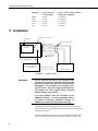
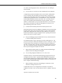
The Motorola M600 Cellular Transceiver has an external RJ11C telephone
interface. A standard RJ11C patch cable connects the Campbell field modem
(COM200, COM210, COM300, COM310) directly to the transceiver. A
computer equipped with the PC208(W) Datalogger Support Software and a
Hayes compatible phone modem connected to a standard phone line is used to
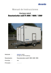
call the cellular equipped stations (see Figure 1-1).
The transceiver is typically not supplied with a handset, but if the user wishes
to place a voice call, any standard analog touchtone telephone can be
connected. However, the field modems and a telephone cannot be connected
1
COM100 Cellular Phone Package
to the transceiver at the same time. Programmable phones will not work with
the transceiver.
2. Specifications
M600 Transceiver
Dimensions:
Operating Temperature:
Supply Voltage:
RF Power Output:
Average Current
Quiescent:
Standby:
On-Line:
*Antenna Termination:
8.4” x 3.9” x 1.0”
-30 to +60°C
+10 to +16 VDC
3 watts nominal
<0.5 mA
<0.17 A
<1.8 A
50 Ohm, mini-UHF female
*Control Relay Crydom D0061B
Control Voltage:
Control Current:
Output Rating:
*See warnings page 4.
2
1.7 to 9 VDC
15 mA @ 5 VDC
.02 - 1.0 ADC @ 3 - 60 VDC
COM100 Cellular Phone Package
Antenna not shown
Phone Lines
Computer Running
PC208 or PC208W
Software
I
S12 S
PERMANENT DAMAGE TO RECHARGEABLE
CELLS MAY RESULT IF DISCHARGED
BELOW 10.5 VOLTS
I 12 I
I
PS12 BATTERY
I
EXTERNAL BATTERY - DO NOT USE WITH
INTERNAL RECHARGEABLE BATTERY
CHARGE VOLTAGE PRESENT
Cellular
Provider’s
Communications
Tower
INPUT FROM CHARGER OR SOLAR PANEL
16-26 VDC OR AC RMS: POSITIVE TO
EITHER TERMINAL, NEGATIVE TO OTHER
12
12
IS
POWER TO DATALOGGER OR
12V PERIPHERALS
thia ia thia ia
thia thia
thia thia
thia thia
thia thia
Logan, Utah
thia thia
thia thia
G 12V
POWER
IN
SW 12V CTRL
SE
DIFF
11 12
5
6
4
H
L AG H
L AG H L AG E3 AG G
7
G
G
8
9
10
SW 12V
G
5V 5V G
CS I/O
thia thia
thia thia
thia thia
G
thia thia
thia thia
thia thia
thia thia
thia thia
thia thia
CR10X WIRING PANEL
MADE IN USA
SE
DIFF
1
2
3
G
H
4
5
2
1
G
L AG H
6
SDM
3
L AG H
tryu to read this whoever
thia thia
G 12V
L AG E1 AG E2 G
P1 G P2
G C8 C7 C6 C5 C4 C3 C2 C1
G 12V 12V
EARTH
GROUND
WIRING
PANEL NO.
CAMPBELL
SCIENTIFIC
INC.
COM200 MODEM
S/N
0002
TIP
RING
This equipment complies with the requirements in Part 15 of FCC Rules for Class A
computing device. Operation of this equipment in a residential area may cause
unacceptable interference to radio and TV reception requiring the operator to take
whatever steps are necessary to correct the interference.
GND
Complies with Part 68, FCC rules. FCC Registration No. B9QUSA-75378-MM-T
Ringer Equivalence 0.6B. Required Connector USOC RJ11C. Canadian Load No.5
MADE IN USA
UNITE DO NOT
D DESIC EAT
STINE,
CANTS
101CHRI
BELEN,
NOW -GATE
MEXICO S
UNITE DO NOT 87002
EAT
101CHRI D DESIC
STINE,
SPECIFIC
CANTS
REACTIV
BELEN,
ATION ATION MIL-D-34
NEW -GATE
DESICCA
MEXICO S
TIME
IN-BAG 64 TYPE
87002
ACTIVAT NT
16 HOURS I &II
CONTEN
BAGGED ED
AT 250
SPECIFICTS
FOR
F
REACTIV 4 ATION PACKAG
UNITS
E
ATION
MIL-D-34
AND USE
DESICCA
TIMEDEHUMID
IN-BAG 64STATIC
TYPE
UNITEACTIVATDONTNOT CONTEN
IFICATIO
16
HOURSN I &II
EAT
D DESIC
ED
101CHRIBAGGED
AT 250 O
STINE, FOR CANTS4 TS
F
PACKAG
BELEN, UNITS
E USE
NOW -GATE
S AND STATIC
MEXICO DEHUMID
UNITE DO NOT 87002 IFICATIO
EAT
101CHRI D DESIC
N
STINE,
SPECIFIC
CANTS
REACTIV
BELEN,
ATION ATION MIL-D-34
NEW -GATE
DESICCA
MEXICO S
TIME
IN-BAG 64 TYPE
87002
ACTIVAT NT
16 HOURS I &II
CONTEN
BAGGED ED
AT 250
SPECIFICTS
FOR
F
REACTIV 4 ATION PACKAG
UNITS
E
ATION
MIL-D-34
AND USE
DESICCA
TIMEDEHUMID
IN-BAG 64STATIC
TYPE
ACTIVAT NT
IFICATIO
16
CONTEN
HOURSN I &II
BAGGED ED
TS
AT 250 O
FOR
4
F
PACKAG
UNITS
E USE
DEHUMIDAND STATIC
IFICATIO
N
DESI
PA
DESI K
PA
K
DESI
PA
DESI K
PA
K
Hayes-Compatible
Modem
FIGURE 1-1. Cellular Telecommunications
3. Antennas
Each transceiver in a cellular phone system must have an antenna. Two
common types of antennas are used, omnidirectional and directional. An
omnidirectional antenna transmits and receives in any direction. A directional
antenna transmits and receives in a particular direction.
Fixed sites are equipped with a directional antenna because it provides the
strongest signal and can be aimed at a cellular repeater site. There are various
shapes of directional antennas, the most common being Yagi antennas, such as
the ASP962.
Mobile applications use omnidirectional antennas. Generally, an
omnidirectional antenna is a spiraled, cylindrical rod, mounted vertically. The
omni antennas listed below differ mainly in mounting hardware.
YAGI ANTENNA (CSI Model 10530)
ASP962 Broadband Yagi
Gain:
Frequency:
Bandwidth:
Input Impedance:
Front to Back Ratio:
VSWR Max:
Dimensions:
Termination
8 dB
806-896 MHz
90 MHz
50 Ohms
15 dB
1.5:1
28.5" x 8.25" x 2.5"
50 Ohm N female
MOBILE OMNI ANTENNAS (Special Order)*
ASPD1894 Mini-UHF Magnetic Mount Antenna
Gain:
3 dB
Frequency:
826-896 MHz
Impedance:
50 ohms
Height:
15"
3
COM100 Cellular Phone Package
ASPD912M Trunk Mount Antenna
Gain:
3 dB
Frequency:
806-869 MHz or824-876 MHz
Bandwidth:
60 MHz @ 1.5:1
75 MHz @ 1.9:1
Impedance:
50 ohms
Height:
24"
ASPD913 Mirror or Side Body Mount Antenna
Gain:
3 dB
Frequency:
824-896 MHz
VSWR Max
1.9:1
Impedance:
50 Ohms
Cable/connector:
17 ft/Mini UHF
ASPD955 Vertical Base Station Antenna
Gain:
3 dB
Power:
500 W
Freq:
806-896 MHz
VSWR Max:
1.5:1
Termination:
N female
*From Allen Telecom (800) 321-9977
Decibel Products (800) 676-5342
4. Power Considerations
The relay included with the cellular phone power control cable allows the
datalogger to switch power to the cellular transceiver. Even so, the relatively
high current required by the cellular transceiver makes it necessary to use a
solar panel, vehicle power system, or AC power to maintain a charge on the
system battery. It is unfeasible to power the datalogger and transceiver from
batteries alone unless the battery capacity is very large, the batteries are
changed frequently, or the transceiver is switched on infrequently.
Since a battery is simply a storage device, a power budget can be calculated to
determine the battery capacity required per day using the following equation:
(standby current drain)*(time in standby mode) + (on-line current drain)*(time
on-line) = Total Amp-hours required
A common application is to turn the transceiver on (in stand-by mode) for 10
minutes at the top of each hour for a full day. This allows ample flexibility for
a user to perform operations such as data-collection, real-time monitoring, new
program downloads, or clock sets. In this example the transceiver was on-line
for 15 minutes of the day to perform the tasks listed above. The Amp hour
usage per day can be calculated as shown in this example:
On-Line time
Stand-by time
Total Time
15 minutes
225 minutes
240 minutes
(0.25 hrs)/day
(3.75 hrs)/day
(4.00 hrs)/day
(0.25hrs/day) x (1.8A) + (3.75hrs/day) x (0.17A) ≈ 1.0 Ahr/day
4
COM100 Cellular Phone Package
Users must also figure datalogger, modem, and sensor contribution into their
power budgets. For example a standard weather station has minimal current
drain but requires an additional 0.25 Ahr/day battery capacity.
Campbell Scientific offers several sealed rechargeable battery options for use
with the COM100 Cellular System. The batteries offered in our product line
are well suited for remote environments where trickle charging by a solar panel
is common. The rechargeable batteries also provide the current required by the
cellular transceiver that cannot be provided directly by the charging source.
Given the previous application, the following Campbell Scientific power
supplies will allow the cellular system to operate for approximately the number
of days listed below. The amount of time assumes there is no charging source
due to AC power failure or a damaged solar panel. Calculations also assume
the batteries are fully charged and at 25°C.
NOTES:
Model
Charging Source/
Notes
Battery
PS12LA
BP12
BP24
1
7 Ahr
1,2
12 Ahr
1,2,3
24 Ahr
Approximate
Operating days
<7
<12
<24
1.
10 watt solar panel recommended as charging source in
remote applications, model MSX10
2.
12VDC regulator, model CH12R
3.
Larger enclosure required, model ENC 16/18
For frequent (fixed site) calling applications without AC power, the MSX20R
Solar Panel or MSX20 and CH12R Regulator is recommended with a usersupplied deep cycle marine or RV battery. If the transceiver is seldom on and
the site receives adequate sunlight, a smaller battery and solar panel may work
(see power calculations).
Other factors in determining the battery size for on-line cellular data collection
is the amount of data being stored, the frequency at which the station is being
called for data collection and the baud rate of the data modem. Listed below
are the typical data storage capacities for our most popular dataloggers and the
amount of time required to collect a full datalogger assuming a reliable cellular
phone connection. It is recommended to collect the data at intervals more
frequent than the time required to fill the datalogger’s memory.
5
COM100 Cellular Phone Package
Datalogger
Storage Capacity
# of Data Points
Approx. Time for Entire Memory
Collection at 1200 Baud
CR500
CR10
CR10X
21X
CR7
24,000
29,908
62,280
19,296
18,396
6.6 minutes
8.3 minutes
17.3 minutes
5.3 minutes
5.1minutes
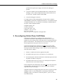
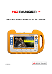
5. Installation
4 Pin RJ11C Connection1
Red LED2
Power Control Cable
COM100
BLACK Ground (G)
RJ11C
Interface
RED
+12 VDC
GREEN Control Port*
Coaxial Cable
to Antenna*
RJ11C Interconnect Cable
DC112, VS1, COM2004
(field modem)
Control
Port
+12V
G
Blue 9-Pin SC12 Cable
DATALOGGER3
FIGURE 5-1. COM100 Wiring
WARNINGS
6
•
Do not connect the Green wire (Crydom relay
control) to the switched +12V power supply on the
black wiring panels used with the CR10 and CR10X
Dataloggers. The maximum input voltage to the
relay is +9 VDC. An input voltage greater than this
will damage the mini Crydom relay contained
within the power control cable.
•
A 50 Ohm Antenna must be connected to the
COM100 at all times. If a call is attempted without
an antenna connected, permanent damage to
COM100 can result which will void the warranty.
1
Connect the field modem patch cable to the 4-pin connector side of the
RJ-11C interface box. The phone modem will not work if it is connected
to the 8-pin connector.
2
When the cellular phone is turned on via the control port, the Red LED
switch on the RJ11C Interface box will flash for about 10 seconds. The
COM100 Cellular Phone Package
LED will glow a steady red when a cellular communications tower and
dial-tone has been detected by the COM100.
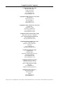
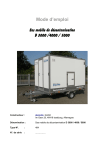
Current Campbell Scientific dataloggers provide 12 VDC to the COM210 via
the SC12 cable (Figure 2). Older dataloggers do not provide 12 VDC on the
datalogger's CS I/O 9 pin connector. When used with the older dataloggers
listed in Table1, 12 VDC and ground need to be connected via the green power
connector on the side of the COM210 (see Figure 3).
Table 1. Dataloggers that Require Direct
12 VDC Connection to COM210
CR10(X) with silver wiring panel
CR10(X) with black CR10 wiring panel (P/N 8032)
21X(L)—serial number 13,442 or lower
CR500serial number 1764 or lower
CR7—700X serial number 2778 or lower
BDR301 and BDR320
DIFF
SE
G G G G
AG H L AG H L AG H L AG E3 AG G G
4
5
6
7 8
9 10
11 12
CAMPE
SCIENTIIC
INC.
SE
1
DIFF
2
3
4
5
6
1
2
3
AG H L AG H L AG H L AG E1 E2 G G
EARTH
SERIAL I/O
MADE IN USA
WIRING PANEL NO.
SWITCHED
12V
CONTROL
G 5V 5V P1 P2
C8 C7 C6 C5 C4 C3 C2 C1
Red
(+12v)
14 AWG Ground Wire
COM210 MO
G 12V
POWER
IN
CR10
To Earth
Ground
CAMPBELL
SCIENTIFIC
INC
12V 12V
SWITCHED
12V
Black
(Ground)
SC12 Cable
DE
.
M
Complies
with
Ringer Equ Part 68, FCC rules
. FCC Reg
ivalence 0.9B
istration No.
.Required
B9QUSA-314
This equipm
Connector
USOC RJ1
02-MM-T
ent complie
computing
1C. Canadia
s with
n Load No.
unacceptabdevice. Operatio the requirements
5
n
whatever le interference of this equipment in Part 15 of FCC
Rules for
to rad
in a residen
steps are
Class A
necessary io and TV rece
tial area
S/N
may cau
ption req
to correc
se
uirin
t the inte
rference. g the operator to
take
G 12V
TIP
IN USA
RING
MADE
GND
1002
Telephone Wall
J k
FIGURE 5-1. CR10X with CR10 Wiring Panel and COM210 Using RJ11C Telephone Jack
7
COM100 Cellular Phone Package
WARNING:
PS12 POWER SPP
PERMANENT DAMAGE TO RECHARGEABLE
CELLS MAY RESULT IF DISCHARGED
BELOW 10.5 VOLTS
WIT 12V CARGING REGATOR
NCTION
AT
INT
EXT
PS12 BATTERY
EXTERNAL BATTERY - DO NOT USE WITH
INTERNAL RECHARGEABLE BATTERY
CHARGE VOLTAGE PRESENT
ON
O
CG
CG
CG
INPUT FROM CHARGER OR SOLAR PANEL
16-26 VDC OR AC RMS: POSITIVE TO
EITHER TERMINAL, NEGATIVE TO OTHER
+12
+12
MADE IN SA
POWER TO DATALOGGER OR
12V PERIPHERALS
thia ia thia ia
thia thia
G 12V
thia thia
Logan, Utah
thia thia
thia thia
G 12V
POWER
IN
SW 12V CTRL
SE
DIFF
11 12
5
6
4
H
L AG H
L AG H L AG E3 AG G
7
G
G
8
9
10
SW 12V
G
5V 5V G
CS I/O
thia thia
thia thia
thia thia
G
tryu to read this whoever
thia thia
thia thia
thia thia
thia thia
thia thia
thia thia
thia thia
thia thia
thia thia
CR10X WIRING PANEL
MADE IN USA
SE
DIFF
1
2
3
G
H
4
5
2
1
G
L AG H
6
SDM
3
L AG H
L AG E1 AG E2 G
P1 G P2
G C8 C7 C6 C5 C4 C3 C2 C1
G 12V 12V
EARTH
GROUND
WIRING
PANEL NO.
CAMPBELL
SCIENTIFIC
INC.
COM200 MODEM
S/N
0002
TIP
RING
This equipment complies with the requirements in Part 15 of FCC Rules for Class A
computing device. Operation of this equipment in a residential area may cause
unacceptable interference to radio and TV reception requiring the operator to take
whatever steps are necessary to correct the interference.
GND
Complies with Part 68, FCC rules. FCC Registration No. B9QUSA-75378-MM-T
Ringer Equivalence 0.6B. Required Connector USOC RJ11C. Canadian Load No.5
MADE IN USA
UNITE
101CHR
DO NO
T EA
D DE
SICCA T
NT
, BEL
EN, NO S-GAT
ES
W ME
O
UNITE DO NOXIC
02
T EA870
D DE
T
ISTINE
DESI
PA
DESI K
PAK
101CHR
ISTINE SICCA
SPE
NT
REACTI CIFICA
, BEL
EN, NEW S-GAT
VATION TION MIL
DESICC
-D-3
MEXIC ES
TIME
IN-BAG 464 TYP
O 870
ACTIVA ANT
02
16 HO E I &II
CONTE
URS
BAGGEDTED
NTS
AT 250
SPE 4
FOR
F
REACTI CIF
PACKAG
UNITS ICATION
VAT
E
ION TIM MIL-D-3
AND USE
DESICC
464STA
EDEH
IN-B
DO
UM
ANTNO
TYP
TIC
UNITEACTIVA
IDIF
AG
E I &II
16ICA
EANTE
HOTIO
D DETED T CO
101CHR BAG
URSN
T NTS
AT 250 O
GED SICCA
ISTINE
FOR NT 4
F
PAC
, BEL
KAGE
EN, NO UNIS-G
USE
W METS ATES
DEHUM AND STA
O
TIC
UNITE DO NOXIC
02 IDIFICATIO
T EA870
101CHR D DE
T
N
ISTINE SICCA
SPE
NT
REACTI CIFICA
, BEL
EN, NEW S-GAT
VATION TION MIL
DESICC
-D-3
MEXIC ES
TIME
IN-BAG 464 TYP
O 870
ACTIVA ANT
02
16 HO E I &II
CONTE
URS
BAGGEDTED
NTS
AT 250
SPE 4
FOR
F
REACTI CIF
PAC
KAGE
UNITS ICATION
VAT
ION TIM MIL-D-3
AND USE
DESICC
464STA
EDEH
IN-B
UM
TYP
TIC
ACTIVA ANT
AGIDIF
E I &II
16ICA
CONTE
HOTIO
URSN
BAGGEDTED
NTS
AT 250 O
FOR
4
F
PACKAG
UNITS
E USE
DEHUM AND STA
IDIFICA TIC
TION
DESI
PA
DESI K
PAK
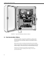
FIGURE 5-2. Typical Field Installation (Antenna not Shown)
6. Communication Notes
Once consistent cellular coverage has been established on a stationary phone,
interference should not be a problem. Interference on mobile phones is more
easily encountered. The local cellular company can verify cellular coverage of
a specific area.
When a transceiver moves, the call may be transferred from one cell to another.
Transceivers generally stay on-line during these transfers, and data are transmitted
properly. However, if all the cells are busy or if too much interference occurs, the
call will be dropped. This causes the transceiver and the field modem to hang up.
Possible sources of interference that should be avoided include heavy
construction sights, tunnels, transmitting from the fringes of an area, and
power transmission lines.
8
COM100 Cellular Phone Package
6.1 Datalogger Support Software
Datalogger support software (PC208, PC208E, PC208W) checks the signature
of each block of data as it is received from the datalogger. A poor connection
will result in the retransmission of incorrectly received blocks. If a link is
consistently noisy, use of smaller block sizes may improve throughput. If the
connection is completely broken, the software will write an error message to
the hard disk. The datalogger support software also keeps track of what data
was successfully collected and will attempt to call the datalogger to collect the
remaining data based on the retry schedule in the station file that was created.
NOTE
If using a relay to switch power to the transceiver, make sure
retries occur at times the transceiver is on
To establish a connection with your remote cellular phone field station requires
setting up your Datalogger Support Software session to call a Campbell Field
Modem and Datalogger. Please refer to your current Datalogger Support
Software Manual for details on setting up a simple phone modem session. The
options listed in our support software do not specifically list the cell phone as
an option. You should choose “ phone modem” or “ hayes modem” when
setting up your station file. As mentioned previously, the COM200/COM210
phone modem used with the COM100 Cellular Phone package supports 300,
1200, 2400, and 4800 baud connections. Campbell Scientific datalogger serial
ports support a 300, 1200, and 9600 baud terminal connection. Additional
commands must be sent to the PC calling modem during the dialing sequence
to allow a 2400 and 4800 baud modem connect speed. Bandwidth limitations
over the Analog Cellular Phone System prevents a reliable modem connection
above 4800 baud.
The command to enable this feature will vary from modem to modem. This
command is added to your initialization string in PC208W. Check your
modem manual to look for a command similar to:
Practical Peripherals Example:
Command
Function
N0
S37=11
S7=90
Originate or answer: Handshake only at speed in S37 register
Set baud rate to connect at 4800 baud
Set modem carrier time-out at 90 seconds
In addition, “ datalogger” extra response times upwards of 3000 msec may be
required as there are variable delays present in the cellular phone system.
NOTE
When a program is downloaded to a station that switches power
to the transceiver, the datalogger will automatically compile the
program. This will cause all control ports to be reset low. If the
downloaded program does not include the instructions to switch
the transceiver back on, it will be necessary to visit the site and
reprogram the datalogger to set a control port high before
resuming cellular communication.
9
COM100 Cellular Phone Package
7. Programming to Switch Transceiver Power
Switching power to the transceiver allows the datalogger to maintain a lower
power budget by limiting communication to predetermined times. The
transceiver must be switched on before it can answer or call.
This section provides examples of datalogger programming to switch power.
If the power supply is sufficient to power the cellular transceiver continuously
without switching, no special programming is necessary.
7.1 Powering on Fixed Intervals
The simplest program switches power on at specific times and off a fixed time
later. This can be accomplished with two Instructions. Instruction 92 sets the
port controlling the relay high to turn the power on and a second Instruction 92
sets the port low. In these examples, control port 1 controls the relay.
The following program switches the transceiver on at midnight for 15 minutes:
;{CR10X}
;
*Table 1 Program
01: 10.0
Execution Interval (seconds)
01: If time is (P92)
1: 0
Minutes (Seconds --) into a
2: 1440
Interval (same units as above)
3: 41
Set Port 1 High
02: If time is (P92)
1: 15
Minutes (Seconds --) into a
2: 1440
Interval (same units as above)
3: 51
Set Port 1 Low
*Table 2 Program
02: 0.0
Execution Interval (seconds)
*Table 3 Subroutines
End Program
With the transceiver on for 15 minutes following midnight, TELCOM would
be set to call automatically once a day at 2 minutes after midnight. In some
areas there are discounts for calls during off hours.
To allow contacting the station throughout the day, the transceiver can be
turned on for the first 10 minutes of each hour:
10
COM100 Cellular Phone Package
;{CR10X}
;
*Table 1 Program
01: 10.0
Execution Interval (seconds)
01: If time is (P92)
1: 0
Minutes (Seconds --) into a
2: 60
Interval (same units as above)
3: 41
Set Port 1 High
02: If time is (P92)
1: 10
Minutes (Seconds --) into a
2: 60
I nterval (same units as above)
3: 51
Set Port 1 Low
*Table 2 Program
02: 0.0
Execution Interval (seconds)
*Table 3 Subroutines
End Program
Or one might want to power the transceiver for one hour at 10 a.m. and at 10
p.m.
;{CR10X}
;
*Table 1 Program
01: 10.0
Execution Interval (seconds)
01: If time is (P92)
1: 600
Minutes (Seconds --) into a
2: 720
Interval (same units as above)
3: 41
Set Port 1 High
02: If time is (P92)
1: 660
Minutes (Seconds --) into a
2: 720
Interval (same units as above)
3: 51
Set Port 1 Low
*Table 2 Program
02: 0.0
Execution Interval (seconds)
*Table 3 Subroutines
End Program
Whatever the time that the program powers the transceiver, the station must be
called while the transceiver is on; it cannot answer a call at other times.
11
COM100 Cellular Phone Package
NOTE
When initiating a call from the datalogger (Instruction 97), the
transceiver must be switched on at least 15 seconds before the
call is placed.
8. Troubleshooting
Below are common things to check when trying to troubleshoot a cellular
phone problem.
1.
No-Answer. You receive a programmed message after several rings that
the cellular customer you are trying to reach has their phone turned off or
has traveled outside of the coverage area.
Q.
Has the cellular phone been programmed by your local service provider
with the telephone number?
Each cellular telephone has a telephone number and an Electronic Serial Number
(ESN) that is unique to each phone to prevent unauthorized use. The telephone
number must match the assigned the ESN. If you try to use a cellular phone that
has not been programmed with the telephone number, the phone will
automatically become locked and will require you to take it to your service
provider to be un-locked.
Q.
Do you know what your system battery voltage is and the type of batteries
being used?
The COM100 and Datalogger requires a nominal supply voltage of 12VDC.
The system will operate between 10 and 16VDC. Since the COM100 draws
1.8 Amps during transmission, lead acid or gel cell type of batteries (PS12LA,
BP12, BP24) must be used. Do not use alkaline batteries (CSI Model BPALK
or PS12ALK) as a power source for the cellular phone. Alkaline batteries have
a high internal resistance and cannot source the high current requirements of
the COM100.
Q.
Is the Campbell field modem plugged into the 4 pin connector on the
external RJ11C interface box that is attached to the side of the cellular
phone?
The COM100 cell phone and RJ11C interface box both have an 8-pin
connector that is for the digital handset. Do not connect the field modem to
these ports, as your system will not work in this configuration. The 4-pin
connection on the RJ11C Interface box is the only compatible port for use with
the field modems.
Q.
Is the Red LED on the RJ11C Interface box turning on after power up?
The RJ11C interface box has a switch to allow you to manually turn the phone
on and off. This is a momentary switch with a Red Light Emitting Diode
(LED) that will flash for about 10 seconds after powering up. The Red LED
should remain on continuously after the COM100 has located the cellular
tower. If the phone is not turning on, press this switch to see if the LED comes
12
COM100 Cellular Phone Package
on. (This is for testing purposes only.) Do not turn if off. See warning in
front of manual.
Q.
Can you call in or out of the site with a standard touch-tone telephone?
A simple analog touch-tone telephone can be used to test the cellular phone
system. Disconnect the field modem from the 4-pin RJ11C Interface box.
Connect your analog phone to this same 4-pin port. Set the control port high
connected to the green control wire. You should hear a “ beep” on power up
and the LED should flash for about 10 seconds. After 10 seconds you will
hear a dial tone and the Red LED should be glowing constantly. Dial a
number to a location where you can verify the call out link. As a second test,
have someone call into the site while the analog phone is connected. The
phone should ring when a call is received.
Q.
Is the directional antenna pointed at the cellular provider tower?
Directional antennas such as the ASPD962 (CSI Model 10530) focus the Radio
Frequency (RF) energy in one direction, and have a greatly reduced radiation
pattern in the opposite direction, this is how gain is achieved. If you are in a
location where cellular coverage is marginal, selective pointing of the antenna
directly at the cell tower will be required.
Q.
Does your datalogger program contain the necessary control instructions
to turn the cellular phone on and off?
The COM100 requires a logic control port to turn the cellular phone on. The
green wire of the power control cable should be wired to a control port. Check
to ensure that the screw terminals are not crimped on the green insulation of
this cable. Instruction P92 is typically used to turn the phone on based on real
rd
time. The 3 parameter of P92 is used typically to turn the phone on and off.
Refer to previous program examples for reference.
2.
When I dial the cellular number, my calling modem and the Datalogger
modem connect but nothing further happens.
Q.
Are you using a high speed Modem (i.e. 14.4, 28.8, 33.6)?
Campbell Scientific’s PC208 and PC208W Datalogger Support Software do
not support local flow control. Typically modem initialization strings must
sent to the phone modem prior to dialing the phone number. Please refer to the
PC208 and PC208W Datalogger Support Software manuals for information on
how to setup the initialization strings.
3.
When I establish a connection to the datalogger I sometimes see odd
characters scrolling across the screen.
Cellular Phones that are on a marginal link can introduce noise that the
computer sees as data. On a very noisy link you will see “ garbage” characters
like:
!@#)*$)*)*!)@$)!#3123313213*Fd
13
COM100 Cellular Phone Package
Campbell Scientific’s PC208 and PC208W software has error checking
algorithms to ensure the integrity of your data even on very noisy links. Given
that the COM100 system typically has power cycled to it, noisy links will take
more time because the suspect data packets are re-sent again to the computer.
If the datalogger sees more than 150 invalid characters, it will terminate the
link. At the PC, one thing a user can try is to reduce the baud rate as low as
300 baud (the field modems are 300 to 4800 baud auto-negotiable). This
reduces the required bandwidth and the data retrieval usually will require less
retries. However, 300 baud data retrieval can take 4 times as long as 1200
baud; hence, this can be a costly solution.
Additional Troubleshooting Notes for COM200/COM210 Phone Modem
1)
Verify nothing else is using the same COM port on the computer. Even if
a program is minimized in windows, it may have a lock on the COM port.
Some notebook computers do not automatically activate the COM ports.
Verify the COM port you are using is activated.
2)
The Campbell Scientific software will display an activity of
communication as the link is being established. Assuming the above
items are O.K., the software should display in the activity window/screen
something such as “ ATDT#######” . Where the #### is the telephone
number listed in the dialing path of the software for the datalogger you
are trying to call.
The local modem attached to the computer will respond back to the
computer with result codes depending on how the call is progressing.
These result codes can be either numeric (0, 1, 2, etc.) or “ verbose”
(“ OK” , “ CONNECT” , “ RING” , etc.). Our software expects numeric
result codes. The result codes may appear on a new line, be appended to
the last line, or may even replace the first letter(s) of the last line. If these
characters are verbose, the initialization string for the modem will need to
be changed. Below is a list of possible result codes. The result code
returned may indicate why the call is unsuccessful.
RESULT CODES:
0
1
2
3
4
5
6
7
8
12
13
17
3)
14
OK
Connect
Ring
No Carrier
Error
Connect 1200 Baud
No Dial Tone
Busy
No Answer
Connect 9600 Baud
Connect 9600/14400 Baud
Connect 9600 Baud
Verify the COM210 is receiving 12 VDC. If the COM210 is receiving 12
VDC from a separate power supply instead of the datalogger, is the
COM100 Cellular Phone Package
ground of the separate power supply connected to the datalogger’s
ground?
4)
Verify the COM210 is the only Modem Enable device connected to the
datalogger. Other common Campbell Scientific modem enable devices
are the SC32A, some RF modems, and the MD9.
5)
Verify the datalogger is turned on.
To comply with FCC Rules and Regulations, all repairs on the COM210
modem must be performed by Campbell Scientific, Inc. or an authorized agent
of Campbell Scientific, Inc. For assistance in installation, troubleshooting, or
for repair, contact Campbell Scientific:
Campbell Scientific, Inc.,
815 West 1800 North
Logan, Utah 84321-1784
Telephone: (435) 753-2342
Fax: (435) 750-9540
Web site: http://www.campbellsci.com/support.htm
9. Re-configuring Cellular Phone On/Off State
This Motorola Cellular Phone is equipped with a feature known as
Convenience On/Off state. When the phone is turned off it saves certain
parameters to non-volatile memory so that they may be remembered when the
phone is turned back on. This includes the on or off state of the phone at the
time the ignition sense line (green wire) was set low (0V).
In unattended installations the datalogger will NOT power up the cellular
phone if the red LED power indicator/switch has been manually turned OFF
(no longer lit) while under datalogger control. There is a specific sequence that
causes this failure to happen:
1.
Primary +12VDC Power has been applied to the phone.
2.
The ignition sense (green wire) is set high (5V) via a control port.
3.
The red LED power indicator/switch has been manually depressed to turn
the phone off (LED is no longer lit).
4.
The ignition sense line is set low (0V) via a control port (stores phone’s
OFF power state to non-volatile memory).
In this configuration the cellular phone will remain off even if the control port
is set high again. The only way to turn the phone back on is to manually
depress the red LED switch again.
Campbell Scientific has configured the phone at the factory to power-up under
datalogger control. If your cellular phone is not turning on while under
datalogger control, you will have to restore the phone’s “ power on” state in
non-volatile memory.
15
COM100 Cellular Phone Package
The following 5 steps must be performed in the exact order listed to restore the
proper “ power on” state:
1.
Connect the antenna via the coaxial cable to the transceiver.
2.
Apply primary power (Ground and +12VDC) to the Black and Red Wires
respectively.
3.
Apply +5VDC power to the ignition sense line (green Wire) by setting a
control port high.
4.
Depress the red LED switch to turn on the phone. LED will flash for
about 10 seconds and then glow a steady RED.
5.
To store this “ ON” power state in the phone’s non-volatile memory,
remove power from the ignition sense line by setting the control port low
(0V).
From this point on the phone will reliably power up and down under
datalogger control. A sample listing of datalogger program code is shown
below to assist a user in steps 3 and 5 from above:
;{CR10}
;
*Table 1 Program
01: 1.0
Execution Interval (seconds)
1: If Flag/Port (P91)
1: 11
Do if Flag 1 is High
2: 41
Set Port 1 High
2: If Flag/Port (P91)
1: 21
Do if Flag 1 is Low
2: 51
Set Port 1 Low
Software flags can be manually toggled high and low via the Datalogger’s
keypad (*6AD1) or through Campbell Scientific’s PC208(W) software. Please
refer to the PC208 and PC208W Datalogger Support Software manuals for
information on how to manually toggle Flags.
16
This is a blank page.
Campbell Scientific Companies
Campbell Scientific, Inc. (CSI)
815 West 1800 North
Logan, Utah 84321
UNITED STATES
www.campbellsci.com
[email protected]
Campbell Scientific Africa Pty. Ltd. (CSAf)
PO Box 2450
Somerset West 7129
SOUTH AFRICA
www.csafrica.co.za
[email protected]
Campbell Scientific Australia Pty. Ltd. (CSA)
PO Box 444
Thuringowa Central
QLD 4812 AUSTRALIA
www.campbellsci.com.au
[email protected]
Campbell Scientific do Brazil Ltda. (CSB)
Rua Luisa Crapsi Orsi, 15 Butantã
CEP: 005543-000 São Paulo SP BRAZIL
www.campbellsci.com.br
[email protected]
Campbell Scientific Canada Corp. (CSC)
11564 - 149th Street NW
Edmonton, Alberta T5M 1W7
CANADA
www.campbellsci.ca
[email protected]
Campbell Scientific Ltd. (CSL)
Campbell Park
80 Hathern Road
Shepshed, Loughborough LE12 9GX
UNITED KINGDOM
www.campbellsci.co.uk
[email protected]
Campbell Scientific Ltd. (France)
Miniparc du Verger - Bat. H
1, rue de Terre Neuve - Les Ulis
91967 COURTABOEUF CEDEX
FRANCE
www.campbellsci.fr
[email protected]
Campbell Scientific Spain, S. L.
Psg. Font 14, local 8
08013 Barcelona
SPAIN
www.campbellsci.es
[email protected]
Please visit www.campbellsci.com to obtain contact information for your local US or International representative.


![かんたんセットアップガイド [PDF形式]](http://vs1.manualzilla.com/store/data/006649499_2-f5e218d35581aa7e4f368b924cae709d-150x150.png)