1
About this Manual
We’ve added this manual to the Agilent website in an effort to help you support
your product. This manual is the best copy we could find; it may be incomplete
or contain dated information. If we find a more recent copy in the future, we will
add it to the Agilent website.
Support for Your Product
Agilent no longer sells or supports this product. Our service centers may be able
to perform calibration if no repair parts are needed, but no other support from
Agilent is available. You will find any other available product information on the
Agilent Test & Measurement website, www.tm.agilent.com.
HP References in this Manual
This manual may contain references to HP or Hewlett-Packard. Please note that
Hewlett-Packard's former test and measurement, semiconductor products and
chemical analysis businesses are now part of Agilent Technologies. We have
made no changes to this manual copy. In other documentation, to reduce
potential confusion, the only change to product numbers and names has been in
the company name prefix: where a product number/name was HP XXXX the
current name/number is now Agilent XXXX. For example, model number
HP8648A is now model number Agilent 8648A.
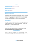
User's Guide
HP 70004A
Color Display
ABCDE
HP Part No. 70004-90061
Printed in USA January 1998
Edition A.0.0
Notice
The information contained in this document is subject to change without notice.
Hewlett-Packard makes no warranty of any kind with regard to this material, including,
but not limited to, the implied warranties of merchantability and tness for a particular
purpose. Hewlett-Packard shall not be liable for errors contained herein or for incidental or
consequential damages in connection with the furnishing, performance, or use of this material.
Restricted Rights Legend.
Use, duplication, or disclosure by the U.S. Government is subject to restrictions as set forth
in subparagraph (c) (1) (ii) of the Rights in Technical Data and Computer Software clause at
DFARS 252.227-7013 for DOD agencies, and subparagraphs (c) (1) and (c) (2) of the Commercial
Computer Software Restricted Rights clause at FAR 52.227-19 for other agencies.
Trademarks
ITEL is a U.S. trademark of Intelligent Interfaces Inc.
c Copyright Hewlett-Packard Company 1990, 1998
All Rights Reserved. Reproduction, adaptation, or translation without prior written permission
is prohibited, except as allowed under the copyright laws.
1400 Fountaingrove Parkway, Santa Rosa, CA 95403-1799, USA
Certication
Hewlett-Packard Company certies that this product met its published specications at the
time of shipment from the factory. Hewlett-Packard further certies that its calibration
measurements are traceable to the United States National Institute of Standards and
Technology, to the extent allowed by the Institute's calibration facility, and to the calibration
facilities of other International Standards Organization members.
Warranty
This Hewlett-Packard instrument product is warranted against defects in material and
workmanship for a period of one year from date of shipment. During the warranty period,
Hewlett-Packard Company will, at its option, either repair or replace products which prove to
be defective.
For warranty service or repair, this product must be returned to a service facility designated by
Hewlett-Packard. Buyer shall prepay shipping charges to Hewlett-Packard and Hewlett-Packard
shall pay shipping charges to return the product to Buyer. However, Buyer shall pay all
shipping charges, duties, and taxes for products returned to Hewlett-Packard from another
country.
Hewlett-Packard warrants that its software and rmware designated by Hewlett-Packard for
use with an instrument will execute its programming instructions when properly installed on
that instrument. Hewlett-Packard does not warrant that the operation of the instrument, or
software, or rmware will be uninterrupted or error-free.
Limitation of Warranty
The foregoing warranty shall not apply to defects resulting from improper or inadequate
maintenance by Buyer, Buyer-supplied software or interfacing, unauthorized modication or
misuse, operation outside of the environmental specications for the product, or improper
site preparation or maintenance.
NO OTHER WARRANTY IS EXPRESSED OR IMPLIED. HEWLETT-PACKARD SPECIFICALLY
DISCLAIMS THE IMPLIED WARRANTIES OF MERCHANTABILITY AND FITNESS FOR A
PARTICULAR PURPOSE.
Exclusive Remedies
THE REMEDIES PROVIDED HEREIN ARE BUYER'S SOLE AND EXCLUSIVE REMEDIES.
HEWLETT-PACKARD SHALL NOT BE LIABLE FOR ANY DIRECT, INDIRECT, SPECIAL,
INCIDENTAL, OR CONSEQUENTIAL DAMAGES, WHETHER BASED ON CONTRACT, TORT,
OR ANY OTHER LEGAL THEORY.
Assistance
Product maintenance agreements and other customer assistance agreements are available for
Hewlett-Packard products.
For any assistance, contact your nearest Hewlett-Packard Sales and Service Oce.
iii
Safety Symbols
The following safety symbols are used throughout this manual. Familiarize yourself with each
of the symbols and its meaning before operating this instrument.
CAUTION
The CAUTION sign denotes a hazard. It calls attention to a procedure which, if
not correctly performed or adhered to, could result in damage to or destruction
of the product or the user's work. Do not proceed beyond a CAUTION sign
until the indicated conditions are fully understood and met.
WARNING
The WARNING sign denotes a hazard. It calls attention to a procedure
which, if not correctly performed or adhered to, could result in injury
to the user. Do not proceed beyond a WARNING sign until the indicated
conditions are fully understood and met.
DANGER
The DANGER sign denotes an imminent hazard to people. It warns the
reader of a procedure which, if not correctly performed or adhered to,
could result in injury or loss of life. Do not proceed beyond a DANGER
sign until the indicated conditions are fully understood and met.
iv
General Safety Considerations
WARNING
The instructions in this document are for use by qualied personnel
only. To avoid electrical shock, do not perform any servicing unless you
are qualied to do so.
The opening of covers or removal of parts is likely to expose dangerous
voltages. Disconnect the instrument from all voltage sources while it is
being opened.
The power cord is connected to internal capacitors that may remain live
for ve seconds after disconnecting the plug from its power supply.
This is a Safety Class 1 Product (provided with a protective earthing
ground incorporated in the power cord). The mains plug shall only be
inserted in a socket outlet provided with a protective earth contact.
Any interruption of the protective conductor inside or outside of the
instrument is likely to make the instrument dangerous. Intentional
interruption is prohibited.
For continued protection against re hazard, replace fuse only with
same type and ratings, (type nA/nV). The use of other fuses or materials
is prohibited.
WARNING
Before this instrument is switched on, make sure it has been properly
grounded through the protective conductor of the ac power cable to a
socket outlet provided with protective earth contact.
Any interruption of the protective (grounding) conductor, inside
or outside the instrument, or disconnection of the protective earth
terminal can result in personal injury.
Before this instrument is switched on, make sure its primary power
circuitry has been adapted to the voltage of the ac power source.
Failure to set the ac power input to the correct voltage could cause
damage to the instrument when the ac power cable is plugged in.
v
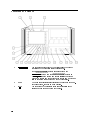
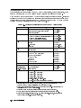
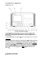
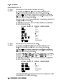
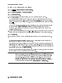
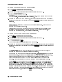
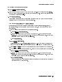
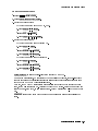
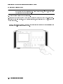
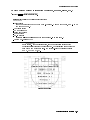
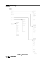
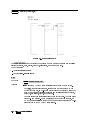
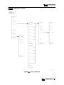
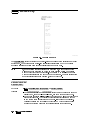
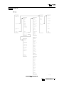
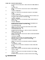
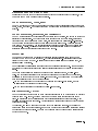
Operation at a Glance
1
INSTR PRESET5
4
Use the instrument preset key to activate all of the preset
conditions of the presently selected instrument.
NNNNNNNNNNNNNNNNNNNNNNNNNNNNNNNNNNNNNNNNNNNN
(The DISPLAY PRESET softkey is dierent from the
4INSTR PRESET5 key; when the DISPLAY PRESET softkey is
pressed, it clears the screen and breaks all links that it has
with any modules and then it oers the screen and a keyboard
link to the last module which had the keyboard link.)
The MSIB fault indicator light indicates the status of the MSIB.
If the light is on, there is an MSIB problem.
Use the local key to reinstate front panel operation if the
instrument has been under remote control.
NNNNNNNNNNNNNNNNNNNNNNNNNNNNNNNNNNNNNNNNNNNN
vi
2
MSIB
3
4
LCL5
PLOT5
4
4
5
4
6
4
7
4
8
4
9
4
10
4
11
4
12
Custom Keypad
13
Knob
14
15
16
4 5 4 5
17
HP-HIL
18
19
20
PRINT5
DISPLAY5
USER5
MENU5
INSTR5
HOLD5
5
5 4
Numeric Keypad
LINE5
4
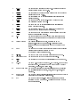
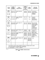
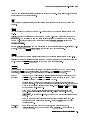
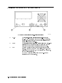
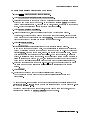
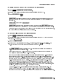
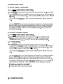
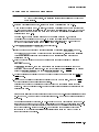
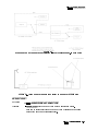
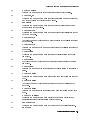
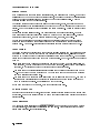
Use the plot key to start a vector (HP-GL) plot output of the
present display screen over HP-IB.
Use the print key to start a raster print output of the present
display screen over HP-IB.
Use the display key to access all display functions through
display softkeys.
Use the user key to access user-dened menus or access
downloadable programs (DLPs).
Use the menu key to access all instrument functions and
system control operations.
Use the instrument key to move (allocate) the display and
keypad between instruments in your system.
Use the hold key to deactivate an active function to prevent
further control setting changes.
Use the backspace key to move from a lower level of menu
keys to the previous level or to backspace the cursor while
entering text.
The custom instrument keypad, provides up to 15
instrument-specic keys on a snap-in panel; the custom
instrument keypad is optional and may not be part of your
system.
Use the knob to change parameters and select other operating
values; this knob is also referred to as an
RPG [Rotary Pulse Generator] knob.
Use the two step keys to change parameters up or down.
Use the numeric keypad to enter numeric values.
Use the line key to switch the display's line power on and o.
Use the HP-HIL port to connect HP-HIL devices. Some devices
supported by HP-HIL include the HP 46021A and HP 98203C
keyboards, HP mouse, and track ball.
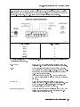
Memory Card Slot The memory card slot provides additional memory for saving
and recalling instrument states, data, user keys, traces, and
programs.
The memory card access light indicates that the memory card is
Memory Card
being read or data is being written on it.
Access Light
BAT
The memory card battery-low light indicates a low battery
condition on the memory card. The light is o if the memory
card is not inserted.
vii
In This Book
This book describes all of the operation procedures and softkeys available under the 4DISPLAY5
key.
Chapter 1 \Hardware Installation", provides information for preparing an HP 70004A
color display for use and using it as part of the structural environment for installing and
conguring instrument modules into HP 70000 Series modular measurement systems.
Chapter 2 \If You Have Problems", provides information to help identify and resolve some
common problems that may occur during or after installation and provides information for
system verication of operation tests.
Chapter 4 \Operating", provides instrument specic front-panel operation instructions.
Chapter 6 \Programming/Remote Operation", provides information on remote programming
and remote operation over HP-IB.
Chapter 7 \Specications and Characteristics", lists the specications and characteristics of
the HP 70004A color display.
Chapter 3 \Front and Rear Panels", describes the menu keys (softkeys and front-panel
keys) as well as various features available through the front-panel and rear-panel of the
HP 70004A color display.
Chapter 5 \Softkey Reference", describes all of the softkeys available through the 4DISPLAY5
key.
Chapter 8 \Error Messages", provides error code information about errors that are reported
on the HP 70004A color display.
Chapter 9 \Concepts", provides concept information that is related to the use of the
HP 70004A color display.
An index is also added at the end of this user's guide to aid the user in nding key items of
interest.
Notation Conventions
This book uses the following notation conventions:
4KEY5
A key name that looks like this represents a key that is physically located on the
instrument and is commonly referred to as a front panel key.
Text that looks like this (with all lowercase letters) represents a softkey that
softkey
accesses another menu of related softkeys.
Text that looks like this (with all uppercase letters) represents a softkey that
SOFTKEY
executes its function.
Display
Text that looks like this represents messages that appear on a display.
Text
Before you begin, you should become familiar with the front panel controls. For information
on what each control is used for, refer to \Operation at a Glance" and Chapter 3.
NNNNNNNNNNNNNNNNNNNNNNN
NNNNNNNNNNNNNNNNNNNNNNN
viii
Contents
1. Hardware Installation
Step 1. Unpacking Your HP 70004A Color Display . . . .
Step 2 (Optional). Installing an Instrument Keypad . . .
Step 3 (Optional). Installing HP-HIL Devices . . . . . . .
Step 4. Connecting Rear Panel Cables . . . . . . . . . .
Step 5. Setting the MSIB and HP-IB Address . . . . . . .
Step 6 (Optional). Connecting for Remote HP-IB Operation
Step 7 (Optional). Connecting an HP-IB Disk Drive . . . .
Step 8 (Optional). Connecting a printer . . . . . . . . .
Step 9 (Optional). Inserting a RAM Memory Card . . . .
Step 10. Connecting the AC Line Power . . . . . . . . .
Step 11 (Optional). Running the Condence Tests . . . .
Accessories and Options . . . . . . . . . . . . . . . .
.
.
.
.
.
.
.
.
.
.
.
.
.
.
.
.
.
.
.
.
.
.
.
.
.
.
.
.
.
.
.
.
.
.
.
.
.
.
.
.
.
.
.
.
.
.
.
.
.
.
.
.
.
.
.
.
.
.
.
.
.
.
.
.
.
.
.
.
.
.
.
.
.
.
.
.
.
.
.
.
.
.
.
.
.
.
.
.
.
.
.
.
.
.
.
.
.
.
.
.
.
.
.
.
.
.
.
.
.
.
.
.
.
.
.
.
.
.
.
.
.
.
.
.
.
.
.
.
.
.
.
.
1-2
1-3
1-5
1-7
1-8
1-9
1-10
1-12
1-14
1-15
1-17
1-18
If the System's Power-On Self Test Fails . . . . . . . . . .
If You Have a Blank or Distorted Display . . . . . . . . .
If One of the HP 70004A Color Display Fault Indicators is On
If More Than One Module's Error Indicator is Flashing . . .
If You Need to Run Display Tests . . . . . . . . . . . . .
If You Have to Clean the Display's Screen . . . . . . . . .
If You Need to Contact Hewlett-Packard . . . . . . . . . .
Returning Your Color Display to Hewlett-Packard . . . . .
.
.
.
.
.
.
.
.
.
.
.
.
.
.
.
.
.
.
.
.
.
.
.
.
.
.
.
.
.
.
.
.
.
.
.
.
.
.
.
.
.
.
.
.
.
.
.
.
.
.
.
.
.
.
.
.
.
.
.
.
.
.
.
.
.
.
.
.
.
.
.
.
.
.
.
.
.
.
.
.
2-2
2-4
2-5
2-7
2-8
2-14
2-15
2-17
2. If You Have Problems
3. Introducing the HP 70004A Color Display
Main Features . . . . . . . . . . . . . . .
Front Panel Regions and Hard-Labeled Keys .
Instrument Keypads for a Spectrum Analyzer
HP-HIL Keyboards . . . . . . . . . . . . .
Rear-Panel Connectors and Address Switches
.
.
.
.
.
.
.
.
.
.
.
.
.
.
.
.
.
.
.
.
.
.
.
.
.
.
.
.
.
.
.
.
.
.
.
.
.
.
.
.
.
.
.
.
.
.
.
.
.
.
.
.
.
.
.
.
.
.
.
.
.
.
.
.
.
.
.
.
.
.
3-2
3-4
3-11
3-13
3-16
Conguring Display Windows . . . . . . . . . . . .
Conguring Display Colors . . . . . . . . . . . . .
Conguring the Display Clock . . . . . . . . . . .
Printing and Plotting . . . . . . . . . . . . . . . .
Selecting and Saving to External Mass Storage Devices
Miscellaneous User Tasks . . . . . . . . . . . . . .
.
.
.
.
.
.
.
.
.
.
.
.
.
.
.
.
.
.
.
.
.
.
.
.
.
.
.
.
.
.
.
.
.
.
.
.
.
.
.
.
.
.
.
.
.
.
.
.
.
.
.
.
.
.
.
.
.
.
.
.
.
.
.
.
.
.
.
.
.
.
.
.
.
.
.
.
.
.
4-2
4-16
4-20
4-22
4-30
4-38
4. Operating/Local MSIB Operation
.
.
.
.
.
.
.
.
.
.
.
.
.
.
.
Contents-1
5. 4DISPLAY5 Softkey Reference
4DISPLAY5 Main
. . . . . .
4DISPLAY5 Hard Copy . . . .
4DISPLAY5 Mass Storage . .
4DISPLAY5 Adjust Color . .
4DISPLAY5 Config Display .
. .
4DISPLAY5 Address Map
4DISPLAY5 Misc
. . . . . .
NNNNNNNNNNNNNN
.
.
.
.
.
.
.
5-3
5-6
5-12
5-15
5-21
5-26
5-29
Programming Commands (Quick Reference) . . . . . . . . . . . . . . . . . .
Programming Commands (Extention Manual Pages) . . . . . . . . . . . . . .
6-1
6-13
NNNNNNNNNNNNNNNNNNNNNNNNNNNNN
NNNNNNNNNNNNNNNNNNNNNNNNNNNNNNNNNNNNNN
NNNNNNNNNNNNNNNNNNNNNNNNNNNNNNNNNNNNNN
NNNNNNNNNNNNNNNNNNNNNNNNNNNNNNNNNNNNNNNNNNNN
NNNNNNNNNNNNNNNNNNNNNNNNNNNNNNNNNNN
NNNNNNNNNNNNNN
.
.
.
.
.
.
.
.
.
.
.
.
.
.
.
.
.
.
.
.
.
.
.
.
.
.
.
.
.
.
.
.
.
.
.
.
.
.
.
.
.
.
.
.
.
.
.
.
.
.
.
.
.
.
.
.
.
.
.
.
.
.
.
.
.
.
.
.
.
.
.
.
.
.
.
.
.
.
.
.
.
.
.
.
.
.
.
.
.
.
.
.
.
.
.
.
.
.
.
.
.
.
.
.
.
.
.
.
.
.
.
.
.
.
.
.
.
.
.
.
.
.
.
.
.
.
.
.
.
.
.
.
.
.
.
.
.
.
.
.
.
.
.
.
.
.
.
.
.
.
.
.
.
.
.
.
.
.
.
.
.
.
.
.
.
.
.
.
6. Programming/Remote Operation
7. Specications and Characteristics
General Specications . . . . . . . . . . . . . . . . . . . . . . . . . . . .
8. Error Messages
2000|2999 Usage Errors . . . . . .
Display-Disruptive Error Messages .
6000|6999 Hardware-Warning Errors
7000|7999 Hardware-Broken Errors
9000|9999 Factory Use Errors . . .
.
.
.
.
.
8-2
8-3
8-5
8-6
8-7
Understanding the HP-IB, MSIB, and the Address Map . . . . . . . . . . . . .
Understanding RGB Video Outputs and Their Use . . . . . . . . . . . . . . .
Understanding the Use of Color . . . . . . . . . . . . . . . . . . . . . . . .
9-2
9-4
9-7
9. Concepts
Index
Contents-2
.
.
.
.
.
.
.
.
.
.
.
.
.
.
.
.
.
.
.
.
.
.
.
.
.
.
.
.
.
.
.
.
.
.
.
.
.
.
.
.
.
.
.
.
.
.
.
.
.
.
.
.
.
.
.
.
.
.
.
.
.
.
.
.
.
.
.
.
.
.
.
.
.
.
.
.
.
.
.
.
.
.
.
.
.
.
.
.
.
.
.
.
.
.
.
.
.
.
.
.
7-2
Figures
1-1.
2-1.
2-2.
2-3.
2-4.
2-5.
2-6.
2-7.
2-8.
4-1.
4-2.
5-1.
5-2.
5-3.
5-4.
5-5.
5-6.
5-7.
5-8.
5-9.
Available ac Power Cords . . . . . . . . . . . . . . . . . . . . . . . . . .
1-19
Line Voltage Selector . . . . . . . . . . . . . . . . . . . . . . . . . . . .
2-2
Line Fuse Removal and Replacement . . . . . . . . . . . . . . . . . . . .
2-3
display tests Menu Keys . . . . . . . . . . . . . . . . . . . . . . . .
2-8
Condence Test . . . . . . . . . . . . . . . . . . . . . . . . . . . . . .
2-9
Key Test . . . . . . . . . . . . . . . . . . . . . . . . . . . . . . . . .
2-10
Knob Test Display . . . . . . . . . . . . . . . . . . . . . . . . . . . . .
2-11
Display ID . . . . . . . . . . . . . . . . . . . . . . . . . . . . . . . . .
2-13
Typical Serial Number Label . . . . . . . . . . . . . . . . . . . . . . . .
2-15
RAM Memory Card Battery Replacement . . . . . . . . . . . . . . . . . .
4-35
Memory Card Date Code Location . . . . . . . . . . . . . . . . . . . . . .
4-36
Main Keys . . . . . . . . . . . . . . . . . . . . . . . . . . . . . . . . .
5-3
Hard Copy Keys . . . . . . . . . . . . . . . . . . . . . . . . . . . . . .
5-6
Mass Storage Keys . . . . . . . . . . . . . . . . . . . . . . . . . . . . .
5-12
Example of an HP 70900B Local Oscillator Source Accessing an HP-IB Disk Drive 5-13
Using MSIB to Connect the Display to a Remote Antenna Site . . . . . . . .
5-13
Adjust Color Keys . . . . . . . . . . . . . . . . . . . . . . . . . . . . .
5-15
Cong Display Keys . . . . . . . . . . . . . . . . . . . . . . . . . . . .
5-21
Address Map Keys . . . . . . . . . . . . . . . . . . . . . . . . . . . . .
5-26
Misc Keys . . . . . . . . . . . . . . . . . . . . . . . . . . . . . . . . .
5-29
NNNNNNNNNNNNNNNNNNNNNNNNNNNNNNNNNNNNNNNNN
Tables
1-1.
1-2.
2-1.
2-2.
2-3.
5-1.
5-2.
5-3.
5-4.
5-5.
5-6.
5-7.
5-8.
Optional Accessories for the HP 70004A Color Display
ITEL Interface Models . . . . . . . . . . . . . . .
Default MSIB Address Map . . . . . . . . . . . . .
HP Service Centers . . . . . . . . . . . . . . . .
Packaging for an 8/8 Module (Color Display) . . . . .
HP PaintJet Color Map . . . . . . . . . . . . . . .
Mapping of Display Pens to Plotter Pens . . . . . . .
Default Values of copy options . . . . . . . . . .
Default Color Values for the Edit Colors Menu . . . .
Default Values for the Monochrome Display . . . . .
Red, Green, and Blue Values for Vision Enhnc 1 . . .
Red, Green, and Blue Values for Vision Enhnc 2 . . .
Red, Green, and Blue Values for the Optical Filter . .
NNNNNNNNNNNNNNNNNNNNNNNNNNNNNNNNNNNNNN
.
.
.
.
.
.
.
.
.
.
.
.
.
.
.
.
.
.
.
.
.
.
.
.
.
.
.
.
.
.
.
.
.
.
.
.
.
.
.
.
.
.
.
.
.
.
.
.
.
.
.
.
.
.
.
.
.
.
.
.
.
.
.
.
.
.
.
.
.
.
.
.
.
.
.
.
.
.
.
.
.
.
.
.
.
.
.
.
.
.
.
.
.
.
.
.
.
.
.
.
.
.
.
.
.
.
.
.
.
.
.
.
.
.
.
.
.
.
.
.
.
.
.
.
.
.
.
.
.
.
.
.
.
.
.
.
.
.
.
.
.
.
.
.
.
.
.
.
.
.
.
.
.
.
.
.
1-18
1-20
2-3
2-16
2-18
5-7
5-9
5-11
5-17
5-18
5-19
5-19
5-20
Contents-3
1
Hardware Installation
This chapter contains information needed to prepare an HP 70004A color display for use in
an HP 70000 Series modular measurement system. The information presented is general in
nature; for more detailed information on cabling congurations, module placement, and MSIB
addressing, refer to the HP 70000 Modular Spectrum Analyzer Installation and Verication
Manual.
Step 1. Unpacking Your HP 70004A Color Display : : : : : : : : : : : : : : : : : : : : : : : : : : : : : : : : : : : : : : : : : : : 1-2
Step 2 (Optional). Installing an Instrument Keypad : : : : : : : : : : : : : : : : : : : : : : : : : : : : : : : : : : : : : : : : : : 1-3
Step 3 (Optional). Installing HP-HIL Devices : : : : : : : : : : : : : : : : : : : : : : : : : : : : : : : : : : : : : : : : : : : : : : : : : 1-5
Step 4. Connecting Rear Panel Cables : : : : : : : : : : : : : : : : : : : : : : : : : : : : : : : : : : : : : : : : : : : : : : : : : : : : : : : 1-7
Step 5. Setting the MSIB and HP-IB Address : : : : : : : : : : : : : : : : : : : : : : : : : : : : : : : : : : : : : : : : : : : : : : : : 1-8
Step 6 (Optional). Connecting for Remote HP-IB Operation : : : : : : : : : : : : : : : : : : : : : : : : : : : : : : : : : 1-9
Step 7 (Optional). Connecting an HP-IB Disk Drive : : : : : : : : : : : : : : : : : : : : : : : : : : : : : : : : : : : : : : : : 1-10
Step 8 (Optional). Connecting a printer : : : : : : : : : : : : : : : : : : : : : : : : : : : : : : : : : : : : : : : : : : : : : : : : : : : : : 1-12
Step 9 (Optional). Inserting a RAM Memory Card : : : : : : : : : : : : : : : : : : : : : : : : : : : : : : : : : : : : : : : : : : 1-14
Step 10. Connecting the AC Line Power : : : : : : : : : : : : : : : : : : : : : : : : : : : : : : : : : : : : : : : : : : : : : : : : : : : : 1-15
Step 11 (Optional). Running the Condence Tests : : : : : : : : : : : : : : : : : : : : : : : : : : : : : : : : : : : : : : : : : : 1-17
Accessories and Options : : : : : : : : : : : : : : : : : : : : : : : : : : : : : : : : : : : : : : : : : : : : : : : : : : : : : : : : : : : : : : : : : : : : : 1-18
Hardware Installation 1-1
Step 1. Unpacking Your HP 70004A Color Display
1 Unpack your color display from its shipping container.
2 Inspect the shipping container and contents thoroughly to ensure that it was not damaged
during shipment.
If the container or cushioning material is damaged, check the contents of the shipment
both mechanically and electrically. If the contents are damaged or defective, contact your
nearest Hewlett-Packard Sales and Service Oce. (Refer to Table 2-2.) Keep the shipping
materials for the carrier's inspection.
3
Verify that all parts and materials were included in the shipping container. (Refer to Table 1-1
for HP part number listings.)
One:
One:
One Set:
One:
(Optional):
(Optional):
(Optional):
(Optional):
HP 70004A color display
HP 70004A Color Display User's Guide
MSIB Rear Panel Cables
AC Power Cord
HP-IB Rear Panel Cables
Instrument Keypads
HP-HIL devices
Memory Cards
1-2 Hardware Installation
Step 2 (Optional). Installing an Instrument Keypad
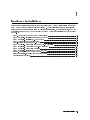
Step 2 (Optional). Installing an Instrument Keypad
To remove an instrument keypad (with release button):
1. Depress the release button, located on the right-hand side of the keypad, and the
instrument keypad should snap out.
To install a custom instrument keypad (with release button):
1. Insert the left side of the keypad (2) into the front panel.
2. Press the right side of the keypad until it snaps into the front panel.
Instrument keypads execute commonly used instrument functions and duplicate operation
of corresponding 4MENU5 softkeys.
There are two dierent release mechanisms for the blank panel:
If the blank panel has a release button on the right-hand side, use the procedure listed
above.
If the blank panel has a slot in the right-hand side, use the procedure on the following page
that utilizes a screwdriver.
Hardware Installation 1-3
Step 2 (Optional). Installing an Instrument Keypad
To remove an instrument keypad (without release button):
1. Insert a bladed screwdriver into the keypad's slot (1).
2. Gently pry the screw-driver's handle to the left. The keypad (2) will snap out of the front
panel.
To install a custom instrument keypad (without release button):
1. Insert the left side of the keypad (2) into the front panel.
2. Press the right side of the keypad until it snaps into the front panel.
Instrument keypads execute commonly used instrument functions and duplicate operation
of corresponding 4MENU5 softkeys.
There are two dierent release mechanisms for the blank panel:
If the blank panel has a release button on the right-hand side, use the procedure on the
previous page that utilizes a screwdriver.
If the blank panel has a slot in the right-hand side, use the procedure listed above.
1-4 Hardware Installation
Step 3 (Optional). Installing HP-HIL Devices
Step 3 (Optional). Installing HP-HIL Devices
To connect a HP-HIL keyboard and a mouse:
1. Inspect the two ends of each HP-HIL cable to locate an end with one black dot and an end
with two black dots.
2. Plug the two-dot end of the HP-HIL cable into the display's two-dot connector.
The end with two black dots is always plugged into the two-dot connector of the device
you are linking from, while the one dot end is always plugged into the one-dot connector
of the device you are linking to.
3. Plug the one-dot end of the HP-HIL cable into the one-dot connector on the keyboard.
4. Plug the two-dot end of the HP-HIL cable that came with the HP mouse or track ball into
the keyboard's two-dot connector.
Note
The HP mouse has only a two-dot end on its HP-HIL cable. Therefore it must be the last
device in the link.
Hardware Installation 1-5
Step 3 (Optional). Installing HP-HIL Devices
To connect an HP mouse or track ball:
Plug the two-dot end of the HP-HIL cable that came with the HP mouse or track ball into
the keyboard's two-dot connector or the two-dot connector of the display; the HP mouse or
track ball do not need a keyboard, they can be connected directly to the display.
The HP-HIL interface supports most relative locator devices including the HP mouse and
track ball.
1-6 Hardware Installation
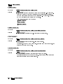
Step 4. Connecting Rear Panel Cables
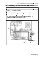
Step 4. Connecting Rear Panel Cables
To connect the display to another display or mainframe:1 2
;
1. Connect an MSIB cable between the HP 70004A color display's MSIB OUT connector (1)
and the HP 70001A mainframe's MSIB IN connector (2).
2. Connect an MSIB cable between the HP 70001A mainframe's MSIB OUT connector (3) and
the HP 70004A color display's MSIB IN connector (4).
The MSIB cables are connected serially, coupling the input of one element to the output of
the next until the loop is completed.
3. The cabling shown in this diagram is for a generic spectrum analyzer system; for more
information about connecting cables between various modules used in an MMS system,
refer to the HP 70000 Modular Spectrum Analyzer Installation and Verication Manual.
1 Each MMS system is shipped with a unique set of precongured cables; the lengths of required cables may vary.
2 For information on connecting to an external monitor, refer to \Understanding RGB Video Outputs and Their Use"
in Chapter 9.
Hardware Installation 1-7
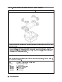
Step 5. Setting the MSIB and HP-IB Address
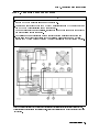
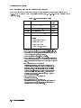
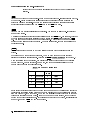
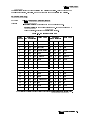
To set the MSIB and HP-IB address switches:
1. Locate the address switches on the rear panel of the display.
2. Set the ve switches labeled COLUMN to the binary value of the display's MSIB column
address.
Setting the COLUMN address of the display, species both the MSIB address and the HP-IB
address of the display.
MSIB Address
HP-IB Address
00000
0
00001
1
00010
2
00011
3
001001
4
To establish proper system function and MSIB communication, each element in a system must
be assigned a unique MSIB address. The MSIB address is selected with an 8-bit binary DIP
(dual in-line package) switch; this 8-bit binary DIP switch is preset for each module at the
factory and may not have to be changed unless you are using a custom addressing
conguration.
Note
Changing MSIB addresses requires an understanding of MSIB addressing rules. If you use a
custom addressing conguration, refer to the HP 70000 Modular Spectrum Analyzer
Installation and Verication Manual.
1 The display section's MSIB COLUMN address is factory-preset to 4 and may be changed, but the display's MSIB ROW
address is permanently set to 0.
1-8 Hardware Installation
Step 6 (Optional). Connecting for Remote HP-IB Operation
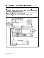
Step 6 (Optional). Connecting for Remote HP-IB Operation
To operate the display remotely:
1. Locate the address switches on the rear panel of the HP 70004A color display.
2. Set the HP-IB switch to the ON position.
3. Connect an HP-IB cable between the HP 70004A color display's HP-IB connector (1) and
the HP 70001A mainframe's HP-IB connector (2).
4. Connect an HP-IB cable between the HP 70001A mainframe's HP-IB connector (2) and
your system controller's HP-IB connector (3).
Your system controller may be any computer/controller (for example, HP 9000
Series 200/300 controller) that supports an HP-IB card.
Hardware Installation 1-9
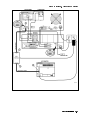
Step 7 (Optional). Connecting an HP-IB Disk Drive
To connect an HP-IB disk drive
1. Locate the HP-IB address switches on the rear panel of the external HP-IB disk drive.
2. Set the HP-IB address switches to 0. Refer to the user's manual for your external HP-IB
disk drive if you use a dierent HP-IB address.
3. Connect an HP-IB cable between the HP 70004A color display's HP-IB connector (1) and
the external HP-IB disk drive's HP-IB connector (2).
Refer to Table 1-1 for recommended models of external HP-IB disk drives.
1-10 Hardware Installation
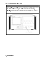
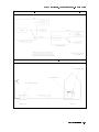
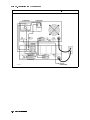
Step 7 (Optional). Connecting an HP-IB Disk Drive
Example of accessing an HP-IB disk drive through an HP 70900B local oscillator source.
Example of using MSIB to connect to a remote antenna site.
Hardware Installation 1-11
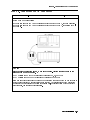
Step 8 (Optional). Connecting a printer
To connect a printer
1. Locate the printer address switches on the rear panel of the printer being connected.
2. Set the address switches to 1. Refer to the user's manual for your printer if you use a
dierent printer address.
3. Connect an HP-IB cable between the HP 70004A color display's HP-IB connector (1) and
the \HP-IB" connector (2) on the ITEL interface. (Refer to Table 1-2 for recommended
ITEL interface models.)
4. Connect a Centronics printer cable between the \Centronics" connector (3) on the ITEL
interface and the printer (4).
To connect a printer to the HP-IB port on the HP 70004A color display, an HP-IB to
Centronics converter is required. The Centronics connector is used to connect to the
Bi-tronics parallel port on the back of many Hewlett-Packard printers. (Refer to Table 1-2.)
1-12 Hardware Installation
Step 8 (Optional). Connecting a printer
Hardware Installation 1-13
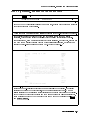
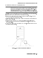
Step 9 (Optional). Inserting a RAM Memory Card
To insert a RAM memory card:
1. Locate the arrow printed on the card label.
2. Insert the card with the arrow on the card matching the arrow above the card-reader slot.
3. Press the card into the slot. When correctly inserted, approximately 19 mm (0.75 in) of
the card is exposed.
Memory cards provide storage media and access routines and instrument personalities; these
are called down-loadable programs (DLPs).
WARNING
Improper card insertion can cause error messages to occur, but generally does not
damage the card or instrument. Care must be taken, however, not to force the card
into the card reader slot.
1-14 Hardware Installation
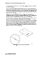
Step 10. Connecting the AC Line Power
Step 10. Connecting the AC Line Power
1 Conrm that the line-voltage selector is set to the proper ac line voltage.
Failure to set the ac power input to the correct voltage could cause one of two things to
happen when power is applied:
If the switch is set to 115 V and the instrument is connected to 230 V, the fuse will blow.
If the switch is set to 230 V and the instrument is connected to 115 V, the instrument will
not turn on.
WARNING
Before turning this instrument on, make sure the line-voltage selector is set to the
voltage of the ac power source.
115 V position for 90 to 132 Vac line input voltages at 50, 60, or 400 Hz
230 V position for 198 to 264 Vac line input voltages at 50 or 60 Hz
Also make sure that it is grounded through the protective conductor of the ac power cable to
a socket outlet provided with protective earth contact. Any interruption of the protective
(grounding) conductor inside or outside the instrument, or disconnection of the protective
earth terminal, can result in personal injury.
Hardware Installation 1-15
Step 10. Connecting the AC Line Power
2 Connect the ac power cord to the display or mainframe's rear panel.
1-16 Hardware Installation
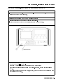
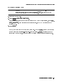
Step 11 (Optional). Running the Condence Tests
Step 11 (Optional). Running the Condence Tests
1 Press the 4DISPLAY5 key.
2 Press the Misc , display tests , and CONFID TEST menu keys to initiate the test.
NNNNNNNNNNNNNN
NNNNNNNNNNNNNNNNNNNNNNNNNNNNNNNNNNNNNNNNN
NNNNNNNNNNNNNNNNNNNNNNNNNNNNNNNNNNN
The Condence Test checks the operation of roughly 90% of the HP 70004A color display.
If the HP 70004A color display fails the Condence Test, it attempts to write an E (error) in
the system state area of the display.
3 Verify that 6001 Confidence test passed appears in the lower-left corner of the screen.
If the display passes the Condence Test, and the display screen shows no visible
distortion, there is a high level of probability that the display is functioning correctly.
If a fault is found, 6008 Confidence test failed is displayed. In this event, refer to \If
You Need to Run Display Tests" in Chapter 2 for additional information, or contact your
nearest Hewlett-Packard Sales and Service Oce. (Refer to Table 2-2.)
At power-on, a set of tests that is dierent from the Condence Test is run. The set of
tests run at power-on includes tests for the MSIB capability of the display. The display
indicates whether any of these tests fail, but does not indicate if they pass. An MSIB
failure is indicated by a blinking E (error) indicator in the system state area of the display.
If the Condence Test produces errors and the MSIB is working (no blinking E indicator),
error messages produced by the Condence Test can be viewed by pressing the 4DISPLAY5
and REPORT ERRORS .
NNNNNNNNNNNNNNNNNNNNNNNNNNNNNNNNNNNNNNNNN
Hardware Installation 1-17
Accessories and Options
The accessories that are supplied with an HP 70004A color display, ordered separately, or as
part of a precongured HP 70000 Series modular measurement system are the same.
When ordered with a precongured HP 70000 Series modular measurement system, cables are
supplied to connect the modules in the particular conguration; for information on dierent
congurations or specic cable lengths and HP part numbers, refer to the HP 70000 Modular
Spectrum Analyzer Installation and Verication Manual.
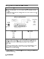
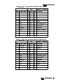
Table 1-1. Optional Accessories for the HP 70004A Color Display
Group
Options
Description
Option 913 Rack mount with handles1
Option 908 Rack mount without handles1
Option 010 Rack slide1
Instrument Keypads HP 70820A microwave transition analyzer
HP 70874A eye diagram analyzer personality DLP
HP 70900A/B local oscillator source
HP 70950A optical spectrum analyzer
HP-HIL Devices
Keyboard
Keyboard
HP-HIL cable2
Track ball
HP-IB Disk Drives 3.5" disk drive
Hard disk drive
Memory Cards
32 KB RAM with battery
128 KB OTP3 ROM with battery
128 KB RAM with battery
256 KB OTP3 ROM
256 KB RAM
512 KB RAM
512 KB OTP3 ROM
AC Power Cables
Power cable
Adapters
RCA to BNC Adapter (3 required)
Hex Ball Driver
8 mm hex ball driver
Thin-Film Cleaner Video Clean Kit
MSIB Cables5
HP 70800A 0.5 m MSIB cable
HP 70800B 1.0 m MSIB cable
HP 70800C 2.0 m MSIB cable
HP 70800D 6.0 m MSIB cable
HP 70800E 30.0 m MSIB cable
HP 70207-60003 2.5 m MSIB Y-cable
HP 70207-20003 MSIB cable adapter (2 Quantity)
HP Part Number
HP 5062-4073
HP 5062-3979
HP 92576
HP 70820-60086
HP 70874-60002
HP 70900-60208
HP 70950-60033
HP 46021A
HP 98203C
HP 46020-60001
HP M1309-60001
HP 9122C
HP 9153C
HP 85700A
HP 85701A
HP 85702A
HP 85703A
HP 85704A
HP 85705A
HP 85706A
Refer to Figure 1-1.4
HP 1250-1853
HP 8710-1651
HP 92193
1 For information on how to rack mount your system, refer to the instructions in HP 70000
Modular Spectrum Analyzer Installation and Verication Manual.
2 This HP-HIL cable is used to connect an HP-HIL keyboard to the HP-HIL connector on the
front panel of the HP 70004A color display.
3 This memory card is One Time Programmable (OTP) Read Only Memory (ROM).
4 The HP part number of the required ac power plug depends on the country of use.
5 To order MSIB cables, in lengths up to 1.2 km, contact Hewlett-Packard. (Refer to \If You
Need to Contact Hewlett-Packard" in Chapter 2.)
1-18 Hardware Installation
Accessories and Options
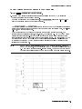
Figure 1-1. Available ac Power Cords
Hardware Installation 1-19
Accessories and Options
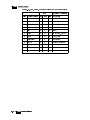
ITEL Interface Models for Connecting Printers
There are a number of Centronics converter models available for connecting printers to the
HP-IB. These models are made by Intelligent Interfaces Inc. (800-842-0888) and are listed in the
following table.
Table 1-2. ITEL Interface Models
Version
Model1
Transfer
Rate
Domestic
ITEL MicroPlot 502 3
Domestic
ITEL MicroPrint 45CV2 ; 4
Domestic
Domestic
International
35 KB/sec to
50 KB/sec
;
ITEL MicroPrint 45CXA2 5
ITEL MicroPrint 45CHVU2 6
ITEL MicroPrint 45CHVE7
;
;
30 KB/sec
30 KB/sec
15 KB/sec
15 KB/sec
Adapters
F1011A #ABB (EUROPE)
F1011A #ABU (UK)
F1011A #ABG (AUS)
F1011A #ACQ (S. AFRICA)
1 To order various models, contact HP DIRECT 1-800-538-8787.
2 ITEL MicroPlot 50 is a product of Intelligent Interfaces Inc. This
model comes with the appropriate ac transformer for use in
North America, Japan, Korea, and Taiwan.
3 This model emulates Hewlett-Packard plotters.
4 ITEL MicroPrint 45CV is a product of Intelligent Interfaces Inc.
This model puts LaserJets in HPGL mode without the need to
set DIP switches like those used with the Model ITEL MicroPrint
45CXA.
5 ITEL MicroPrint 45CXA is a product of
Intelligent Interfaces Inc. This unit can be ordered with a
variable resolution option which allows the resolution of the
printer to be set via DIP switches (it sends the appropriate
escape sequences). This option is useful when the printer
defaults to high-resolution mode which can cause a printout
to be about the size of a postage stamp. This is a common
occurrence when other HP-IB instruments dump traces to
DeskJet Portable printers.
6 ITEL MicroPrint 45CHVU is a product of
Intelligent Interfaces Inc.
7 ITEL MicroPrint 45CHVE is a product of
Intelligent Interfaces Inc. This model is for international use
and does not come with a particular ac transformer; an ac
transformer must be ordered separately.
1-20 Hardware Installation
2
If You Have Problems
This section contains information to help identify and resolve some common problems that may
occur with your color display before the need for extensive servicing.
Symptoms of various problems are listed at the top of each page. Most symptoms have a brief
description or explanation to help provide more insight into their cause. A possible cause for
the symptom and a checklist of possible solutions are then presented. Use this checklist as an
aid to correct the problem.
If the System's Power-On Self Test Fails : : : : : : : : : : : : : : : : : : : : : : : : : : : : : : : : : : : : : : : : : : : : : : : : : : : : : 2-2
If You Have a Blank or Distorted Display : : : : : : : : : : : : : : : : : : : : : : : : : : : : : : : : : : : : : : : : : : : : : : : : : : : : 2-4
If One of the HP 70004A Color Display Fault Indicators is On : : : : : : : : : : : : : : : : : : : : : : : : : : : : : : : 2-5
If More Than One Module's Error Indicator is Flashing : : : : : : : : : : : : : : : : : : : : : : : : : : : : : : : : : : : : : : 2-7
If You Need to Run Display Tests : : : : : : : : : : : : : : : : : : : : : : : : : : : : : : : : : : : : : : : : : : : : : : : : : : : : : : : : : : : : : 2-8
If You Need to Contact Hewlett-Packard : : : : : : : : : : : : : : : : : : : : : : : : : : : : : : : : : : : : : : : : : : : : : : : : : : : : 2-14
Returning Your Color Display to Hewlett-Packard : : : : : : : : : : : : : : : : : : : : : : : : : : : : : : : : : : : : : : : : : : 2-16
If You Have Problems 2-1
If the System's Power-On Self Test Fails
Each time the HP 70000 Series modular spectrum analyzer system is turned on, the system runs
through an initializing routine (power-on self test) during which the front panel STATUS LEDs
on each module ash on momentarily and then turn o.
The display also executes a power-on self-test when power is applied. If the test fails, the
display terminates the sequence and displays an error on the screen in large block letters. One
of the instrument functions tested is the ability of the display section to communicate on the
system bus (MSIB). The results of the test can be determined by examining the system state
area located in the upper-left corner of the display screen.
The following conditions for the display section should exist after the power-on self-test:
The MSIB fault indicator should be o.
The display's fan noise will be scarcely noticeable.
If the system passes the power-on self test, the MEASURE LED on the local oscillator module
begins blinking on and o (triggered by the system sweep), and the ACT LED on each active
module's front panel is turned on.
Common problems that may occur:
If any module fails the power-on self test, it will not establish a link with the display.
If the front panel LEDs on the HP 70900A/B local oscillator source ash on and o, it means
the instrument has failed the power-on self test.
If the display section's power-on self test fails, a blinking E will appear in the status box of
the display.
This error is the same as the red LED marked \ERR" on other HP 70000 Series modules. Its
purpose is to indicate an error detected in the system on MSIB row 0 of the address map.
To solve these common problems:
Check that the HP 70900A/B local oscillator source is powered on.
Check that the HP 70000 Series modular spectrum analyzer system display and mainframe
are plugged into the proper ac line voltage.
Check that the line socket has ac line voltage.
Check that the line voltage selector switch is set to the correct voltage for the ac line voltage
being used. The line voltage selector switch is located on the left side of the HP 70004A
color display, on the bottom of the HP 70001A mainframe.
Figure 2-1. Line Voltage Selector
Check the line fuse on the display or the mainframe to ensure that it is not damaged. The
line fuse is located inside the power-cord receptacle housing on the rear of the display and
2-2 If You Have Problems
If the System's Power-On Self Test Fails
mainframe. Also included in this housing is a spare fuse. The fuse is a 5 by 20 mm fuse rated
at 6.3 A, 250 V (HP part number 2110-0703). This line fuse can be used with both 120 V and
230 V line voltage.
Figure 2-2. Line Fuse Removal and Replacement
Check the system interconnections.
Check the address map as shown in Table 2-1.
Run the Condence Test. (Refer to \If You Need to Run Display Tests".)
The Condence Test checks the operation of about 90% of the display.
If the Condence Test runs successfully, the rst error was probably a system failure, not a
display failure.
If necessary, obtain service from Hewlett-Packard. Refer to \If You Need to Contact
Hewlett-Packard".
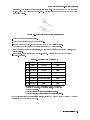
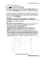
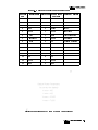
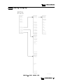
Table 2-1. Default MSIB Address Map
Row 7
Column 18
Column 19
Column 20
blank
HP 70310
blank
Row 6
RF sections1
HP 70300
HP 70620 or HP 706212
Row 5
HP 70907
HP 70301
blank
Row 4
HP 70903
blank
Row 3
HP 70911
HP 70620 or HP 706213
HP 70810 Option 850
Row 2
HP 70700
HP 70600 or HP 70601
blank
Row 1
HP 70902
blank
blank
Row 0
HP 70900
blank
blank
HP 70810
1 This includes: HP 70904A RF section, HP 70905A/B RF section,
HP 70906A/B RF section, HP 70908A RF section, HP 70909A or
HP 70910A RF section.
2 When preamplifying the lightwave section's input signal.
3 When preamplifying the preselector's or RF section's input signal.
For more information about addressing criteria, refer to HP 70000 Modular Spectrum Analyzer
Installation and Verication Manual.
If You Have Problems 2-3
If You Have a Blank or Distorted Display
To solve this problem:
Verify that your display is powered on.
Verify that the intensity is turned on.
If necessary, obtain service from Hewlett-Packard. (Refer to \If You Need to Contact
Hewlett-Packard".)
2-4 If You Have Problems
If One of the HP 70004A Color Display Fault Indicators is On
If One of the HP 70004A Color Display Fault Indicators is On
Problems external to the display can cause the indicators to turn on.
The HP 70004A color display has four fault indicators:
An MSIB indicator on the upper-left corner of the front panel.
A blinking red E in the status box in the upper-left corner of the display.
A steady red E in the status box in the upper-left corner of the display.
A red battery-low indicator next to the RAM memory card access slot.
If you have an MSIB fault indicator on
The HP 70004A color display has an MSIB system fault indicator in the upper-left corner of
the front panel. This indicator applies to the I/O backplane and all modules in the system,
not just the display system; the MSIB indicator should be OFF indicating normal operation.
This circuitry senses the readiness of the external MSIB. If the MSIB indicator light is on,
MSIB communications are inhibited and the condition must be cleared before the display will
operate.
The MSIB indicator light will be on if one of the following conditions is true:
The external MSIB loop is not complete.
Check that both ends of all MSIB cables are securely connected.
If more than one mainframe is used, or if other elements are connected to the MSIB, all
cables must be connected; otherwise, the MSIB will not operate. If a single mainframe with
no external elements is used, there should be no MSIB cables connected to the external MSIB
connectors of that mainframe, although a single cable looped from the input connector to the
output connector will allow the mainframe to operate.
Not all the elements on the external MSIB loop have the power turned on.
Verify that the power is on to the display, all mainframes, and stand-alone instruments on the
external MSIB.
To isolate the problem:
Disconnect both MSIB cables from the display rear panel. Is the MSIB indicator light still on?
NO The problem is either with the cables or an element that was connected to the display
with the cables.
Loop each cable (one at a time) from the display MSIB IN to OUT connectors. If the
MSIB indicator comes on, that cable has probably failed. If the light does not come on
for any of the cables, then an element connected with these cables is faulty. If an
element is determined to be at fault, contact your nearest Hewlett-Packard sales and
service oce for repair.
YES The HP 70004A color display is probably faulty. Contact your nearest Hewlett-Packard
sales and service oce for repair.
If You Have Problems 2-5
If One of the HP 70004A Color Display Fault Indicators is On
If you have a blinking E indicator
The E indicator in the status box in the upper-left corner of the display is the same as the red
LED marked \ERR" on other HP 70000 Series modules. Its purpose is to indicate an error
detected in the system on MSIB row 0 of the address map. A blinking E or ERR LED has a
special meaning: it signies that a problem on the MSIB backplane has been detected during
system power-up which may prevent normal communication between any modules (and hence,
normal error reporting). Such a problem must be resolved before any predictable system
operation can take place.
Remove all MSIB cables from the display's rear panel, all modules from the mainframe section,
and cycle power.
1. If the red E indicator on the display still blinks, then contact your nearest Hewlett-Packard
sales and service oce.
2. If the E indicator does not blink, then connect a known good MSIB cable between the rear
panel MSIB IN and OUT connectors and cycle power. If the E now blinks, contact your
nearest Hewlett-Packard sales and service oce for repair.
3. If the red E indicator stops blinking, insert the modules one by one until the E starts
blinking. When the indicator starts blinking, check the modules for the same MSIB address.
4. If the E indicator doesn't blink, the problem is probably in another display or mainframe,
refer to either the HP 70001A Mainframe Installation and Verication Manual or the
HP 70205A Graphics Display and HP 70206A System Graphics Displays Installation and
Verication Manual for more information about mainframe troubleshooting.
5. If the cursor (rectangle) cannot be moved about within the address map after a module has
been re-addressed, check to see if two modules have the same row and column address. If
so, removal of one of the oending modules is required. See the Installation and Verication
Manual for your instrument for instructions.
MSIB addresses must be unique. Setting two HP 70000 Series modular measurement
system elements to the same address will create an error and make the system bus (MSIB)
inoperative.
If you have a steady E indicator
A module (or the display) has detected an error. Press 4DISPLAY5 and REPORT ERRORS
to identify the modules reporting errors. (Refer to the REPORT ERRORS key for more
information.)
NNNNNNNNNNNNNNNNNNNNNNNNNNNNNNNNNNNNNNNNN
NNNNNNNNNNNNNNNNNNNNNNNNNNNNNNNNNNNNNNNNN
If you have a RAM memory card battery-low indicator light on
The display has a RAM memory card battery-low fault indicator near the memory-card slot in
the lower-right corner of front panel.
The battery-low indicator will indicate on if the battery voltage is too low. The
battery-low indicator will be o if there is no RAM memory card in the slot or if a
one-time-programmable ROM memory card is being used.
2-6 If You Have Problems
If More Than One Module's Error Indicator is Flashing
If More Than One Module's Error Indicator is Flashing
The HP 70004A color display communicates with the HP 70000 Series modular spectrum
analyzer system over the MSIB. When the STATUS ERR indicator LED on a particular module
ashes at a 1 Hz rate, the module cannot communicate over the MSIB.
To solve this problem:
Try turning o the power to the system and then turning it on again.
If front panel keys are still responding, check the address map to see that all modules are
located in their designated coordinates.
If front panel keys are not responding and the address map cannot be checked, power-down
the system, pull out each module and check its address setting by looking at its address
switches.
All modules should conform to the required coordinates on the address map. (Refer to
Table 2-1.)
If your system contains more than one mainframe, check that the MSIB cables are connected
such that two cable connections are made to each mainframe. If these cable connections
look correct, you may try replacing the MSIB cables with new ones.
If necessary, obtain service from Hewlett-Packard. (Refer to \If You Need to Contact
Hewlett-Packard".)
If You Have Problems 2-7
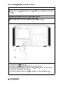
If You Need to Run Display Tests
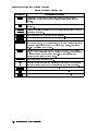
The Display Tests are the display diagnostic and adjustment routines. The Display Tests screen
is accessed by pressing 4DISPLAY5 Misc display tests .
NNNNNNNNNNNNNN NNNNNNNNNNNNNNNNNNNNNNNNNNNNNNNNNNNNNNNNN
WARNING
Keep in mind that display internal adjustments or repairs should only be
attempted by qualied technical personnel.
Figure 2-3. display tests Menu Keys
NNNNNNNNNNNNNNNNNNNNNNNNNNNNNNNNNNNNNNNNN
2-8 If You Have Problems
If You Need to Run Display Tests
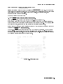
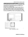
Condence Test ( CONFID TEST Menu Key)
WWWWWWWWWWWWWWWWWWWWWWWWWWWWWWWWWWWWWWWWWWWWWW
NNNNNNNNNNNNNNNNNNNNNNNNNNNNNNNNNNN
Initiate the Display Condence Test by pressing the CONFID TEST menu key. The Condence
Test checks the operation of roughly 90% of the display. If no fault is found, 6001 confidence
test passed appears in the lower-left corner of the screen. If a fault is found, 6008
confidence test failed is displayed.
To run the Display Condence Test:
1. Press 4DISPLAY5 Misc display tests CONFID TEST .
NNNNNNNNNNNNNN NNNNNNNNNNNNNNNNNNNNNNNNNNNNNNNNNNNNNNNNN NNNNNNNNNNNNNNNNNNNNNNNNNNNNNNNNNNN
If an error is detected, contact your nearest Hewlett-Packard service oce.
If the display passes the Condence Test, and the display screen shows no visible distortion,
there is a high level of probability that the display is functioning correctly. If the display fails
the Condence Test, it attempts to write E (error) in the display status block.
If the MSIB is working, any error messages produced by the Condence Test can be viewed by
pressing the 4DISPLAY5 and REPORT ERRORS .
NNNNNNNNNNNNNNNNNNNNNNNNNNNNNNNNNNNNNNNNN
At power-on, a set of tests that is dierent from the Condence Test is run. The set of tests
run at power-on includes tests for the MSIB capability of the display. The display indicates
whether any of these tests fail, but does not indicate if they pass. An MSIB failure is indicated
by a blinking E (error) indicator in the status block.
Figure 2-4. Condence Test
If You Have Problems 2-9
If You Need to Run Display Tests
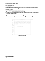
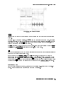
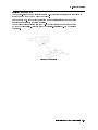
Key Test Menu Key
NNNNNNNNNNNNNNNNNNNNNNNNNN
The KEY TEST menu key allows the user to check the mechanical and electrical operation of
every front panel key on the display.
To run the key test:
1. Press 4DISPLAY5 Misc display tests KEY TEST .
NNNNNNNNNNNNNN NNNNNNNNNNNNNNNNNNNNNNNNNNNNNNNNNNNNNNNNN NNNNNNNNNNNNNNNNNNNNNNNNNN
2. Press any key on the display's front panel. The pressed key will be echoed on the screen if
the key is working properly.
3. Press the backspace key 4 5 to exit the Key Test.
If an error is detected, contact your nearest Hewlett-Packard service oce.
Figure 2-5. Key Test
2-10 If You Have Problems
If You Need to Run Display Tests
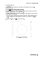
Knob Test Menu Key
NNNNNNNNNNNNNNNNNNNNNNNNNNNNN
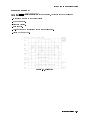
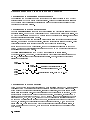
The KNOB TEST menu key allows the user to test the front panel knob on the display.
To run the knob test:
1. Press 4DISPLAY5 Misc display tests KNOB TEST .
NNNNNNNNNNNNNN NNNNNNNNNNNNNNNNNNNNNNNNNNNNNNNNNNNNNNNNN NNNNNNNNNNNNNNNNNNNNNNNNNNNNN
2. Turn the front panel knob clockwise slowly. The numbers in the center of the Knob Test
display should increase one by one (from 00 to 39).
3. Turn the front panel knob counterclockwise slowly. The numbers in the center of the Knob
Test display should decrease.
If the knob is turned swiftly, the numbers in the center of the display should increase and
decrease swiftly. The numbers will change too quickly for you to follow the one-by-one
count.
4. Press the back-arrow key 4 5 to exit the Knob Test.
Figure 2-6. Knob Test Display
If You Have Problems 2-11
If You Need to Run Display Tests
Tumble Figures Menu Key
While the tumble gures are running, the display cannot communicate on
Note
either HP-IB or MSIB. Nor can the display respond to any front panel keys
except the back-arrow key 4 5 and the TUMBLE FIGURES menu keys used to
select the various demonstration gures.
NNNNNNNNNNNNNNNNNNNNNNNNNNNNNNNNNNNNNNNNNNNN
NNNNNNNNNNNNNNNNNNNNNNNNNNNNNNNNNNNNNNNNNNNN
The TUMBLE FIGURES key allows the user to chose ve dierent demonstration routines:
To run the tumble gures test:
1. Press 4DISPLAY5 Misc display tests TUMBLE FIGURES .
NNNNNNNNNNNNNN NNNNNNNNNNNNNNNNNNNNNNNNNNNNNNNNNNNNNNNNN NNNNNNNNNNNNNNNNNNNNNNNNNNNNNNNNNNNNNNNNNNNN
2. Press one of the following menu keys: CUBE , BALL , SLAB , ROD , or HALF .
NNNNNNNNNNNNNN
NNNNNNNNNNNNNN
NNNNNNNNNNNNNN
NNNNNNNNNNN
NNNNNNNNNNNNNN
The tumble gures become larger or smaller when the front panel knob is turned.
3. To exit the tumble gures, press the 4 5 key.
Test Pattern Menu Keys
This key provides a menu of test patterns which are used to adjust the display. For
explanations of the test patterns and related adjustments, refer to the HP 70004A Service
Guide.
2-12 If You Have Problems
If You Need to Run Display Tests
Display ID Menu Key
When the 4DISPLAY5 Misc DISPLAY ID keys are pressed, the screen shows the following
information:
16 squares with each of the current colors
HP model number.
Firmware version.
MSIB address.
HP-IB address (OFF if disabled with the rear panel switch).
Custom Keypad ID Code.
NNNNNNNNNNNNNN NNNNNNNNNNNNNNNNNNNNNNNNNNNNNNNN
Figure 2-7. Display ID
If You Have Problems 2-13
If You Have to Clean the Display's Screen
To clean the display's screen
To avoid damaging the coating on the display screen, use a thin-lm cleaner such as
Hewlett-Packard Video Clean Kit (HP part number 92193). The kit includes an abrasion-free
cleaning cloth.
2-14 If You Have Problems
If You Need to Contact Hewlett-Packard
If You Need to Contact Hewlett-Packard
Before calling Hewlett-Packard or returning your color display, please read your warranty
information. Warranty information is printed at the front of this document.
In any correspondence or telephone conversations, refer to the color display by its full model
number and full serial number. With this information, the Hewlett-Packard representative can
determine whether your unit is still within its warranty period.
Determining Your Color Display's Serial Number
When a module is manufactured by Hewlett-Packard, it is given a unique serial number. This
serial number is attached to a label on the front frame or front panel of the module. A serial
number label is in two parts. (Refer to Figure 2-8.)
The rst part makes up the serial number prex and consists of four digits and a letter. The
second part makes up the serial number sux and consists of the last ve digits on the serial
number label. The serial number prex is the same for all identical modules; it only changes
when a change in the electrical or physical functionality is made. The serial number sux,
however, changes sequentially and is dierent for each module.
Figure 2-8. Typical Serial Number Label
If You Have Problems 2-15
If You Need to Contact Hewlett-Packard
A current list of Hewlett-Packard Service Centers can be accessed on the Internet at:
http://www.tmo.hp.com/tmo/contacts/
If you do not have access to the Internet, one of the following Hewlett-Packard locations can
direct you to your nearest Hewlett-Packard representative:
Table 2-2. HP Service Centers
United States
Canada
Europe
Japan
Latin America
Austrailia/New
Zealand
Asia-Pacic
2-16 If You Have Problems
Hewlett-Packard Company
Test and Measurement Call Center
24 Inverness Place East
Englewood, CO 80112
(800) 403-0801
(800) 857-8161 (FAX)
Hewlett-Packard Canada Ltd.
5150 Spectrum Way
Mississauga, Ontario L4W 5G1
(905) 206-4725
(905) 206-4739 (FAX)
Hewlett-Packard European Marketing Centre
Postbox 667
1180 AR Arnstelveen
Netherlands
(31/20) 547-6669
(31/20) 647-8706
Hewlett-Packard Japan Ltd.
27-15, Yabe 1-Chome,
Sagamihara, Kanagawa 229
Japan
(81426) 567 832
(81426) 567 843 (FAX)
Hewlett-Packard Latin America Region Headquarters
5200 Blue Lagoon Drive, 9th Floor
Miami, Florida 33126
U.S.A.
(305) 267 4245
(305) 267 4288 (FAX)
Hewlett-Packard Calibration Services Austrailia Ltd.
31-41 Joseph Street
Blackburn, Victoria 3130
Austrailia
1800 802 540
1800 681 776 (FAX)
Hewlett-Packard Asia-Pacic Ltd.
17-21/F Shell Tower, Times Square
1 Matheson Street, Causeway Bay
Hong Kong
(852) 25 997 777
(852) 25 069 261 (FAX)
Returning Your Color Display to Hewlett-Packard
Returning Your Color Display to Hewlett-Packard
Hewlett-Packard has sales and service oces around the world to provide complete support for
your color display. To obtain servicing information or to order replacement parts, contact the
nearest Hewlett-Packard sales and service oce listed in Table 2-2.
Use the following procedure to return your color display to Hewlett-Packard:
1. Fill out a service tag (available at the end of this document) and attach it to the instrument.
Please be as specic as possible about the nature of the problem. Send a copy of any or all
of the following information:
any error messages that appeared on the HP 70000 Series display
a completed Performance Test record
any other specic data on the performance of the color display
CAUTION
Damage can result if the original packaging materials are not used. Packaging
materials should be anti-static and should cushion the color display on all sides.
Never use styrene pellets in any shape as packaging materials. They do not
adequately cushion the instrument or prevent it from moving in the shipping
container. Styrene pellets can also cause equipment damage by generating
static electricity or by lodging in fan motors.
2. Place the color display in its original packaging materials.
If the original packaging materials are not available, you can contact a Hewlett-Packard
sales and service oce to obtain information on packaging materials or you may use an
alternative packing material referred to as \bubble-pack". One of the companies that makes
bubble-pack is Sealed Air Corporation of Hayward, California, 94545.
3. Surround the color display with at least 3 to 4 inches of its original packing material or
bubble-pack to prevent the color display from moving in its shipping container.
4. Place the color display, after wrapping it with packing material, in its original shipping
container or a strong shipping container that is made of double-walled corrugated cardboard
with 159 kg (350 lb) bursting strength.
The shipping container must be both large enough and strong enough to accommodate your
color display and allow at least 3 to 4 inches on all sides for packing material.
5. Seal the shipping container securely with strong nylon adhesive tape.
6. Mark the shipping container \FRAGILE, HANDLE WITH CARE" to help ensure careful
handling.
7. Retain copies of all shipping papers.
If You Have Problems 2-17
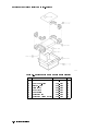
Returning Your Color Display to Hewlett-Packard
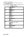
Table 2-3. Packaging for an 8/8 Module (Color Display)
Item
Description
HP Part Number Qty
1
2
3
4
5
6
7
8
2-18 If You Have Problems
Corrugated Carton (Top)
Foam Corner-Pads
Flat End-Cap
Static Sheet
Front Cover
Foam Plastic
Corrugated Pad
Corrugated Carton (Outer)
9211-6785
5040-6967
9220-4962
9222-1806
5040-6974
4208-1210
9220-5072
9211-7065
1
8
1
1
1
1
1
1
3
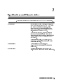
Introducing the HP 70004A Color Display
Summary
In this chapter you will learn about:
Main features of the HP 70004A color display.
Regions of the display screen, and the kinds of information that can be found
in each region.
Front panel hard-labeled keys and their use.
Instrument keypads that can be selected.
Rear-panel connectors.
Address switches.
This chapter presents a rst look at the HP 70004A color display. You will be introduced to
some of the main features. Then, you will learn about the dierent regions of the display, what
each of the front panel hard-labeled keys can do, as well as how to use and access dierent
instrument keypads. Finally, you'll learn about available HP-HIL keyboards, followed by
descriptions of the rear-panel connectors and address switches.
Main Features : : : : : : : : : : : : : : : : : : : : : : : : : : : : : : : : : : : : : : : : : : : : : : : : : : : : : : : : : : : : : : : : : : : : : : : : : : : : : : : : : 3-2
Front Panel Regions and Hard-Labeled Keys : : : : : : : : : : : : : : : : : : : : : : : : : : : : : : : : : : : : : : : : : : : : : : : : : 3-4
Instrument Keypads for a Spectrum Analyzer : : : : : : : : : : : : : : : : : : : : : : : : : : : : : : : : : : : : : : : : : : : : : : 3-11
HP-HIL Keyboards : : : : : : : : : : : : : : : : : : : : : : : : : : : : : : : : : : : : : : : : : : : : : : : : : : : : : : : : : : : : : : : : : : : : : : : : : : : 3-13
Rear-Panel Connectors and Address Switches : : : : : : : : : : : : : : : : : : : : : : : : : : : : : : : : : : : : : : : : : : : : : : : 3-16
Introducing the HP 70004A Color Display
3-1
Main Features
The HP 70004A color display is a rugged structure into which modules of various widths can
be placed; it serves as the \front panel" for instruments in the HP 70000 Series modular
measurement system and provides a graphics display and front panel interface. It is possible to
use one display with multiple measurement systems, one display for a single system, or even
multiple displays for the same system.
The HP 70004A color display has the following features:
Display Section The display section uses menu keys, data and control keys, and a digital-control
knob to assist system operation.
It uses a 7.5-inch diagonal display screen to show system conguration
information, measurement results, text, graphics, and built-in trace and marker
capabilities in up to 16 simultaneous colors (selectable from a palette of 4096
colors) at a resolution of 1024 horizontal by 400 vertical pixels.
The display section of the HP 70004A color display fullls the same function as
the HP 70206A system graphics display or the HP 70205A graphics display.
Mainframe
Plug-in modules can be installed in the mainframe section of the display
to create dierent instruments in the modular measurement system. The
Section
mainframe section provides the structural environment for plug-in instrument
modules along with cooling, power, digital communication interface buses, and
EMI shielding that can accommodate 1/8, 2/8, 3/8, and 4/8-width modules, but
has a maximum capacity of four 1/8-width modules.
Menu Keys
The color display has one screen with 14 menu keys (softkeys). The softkeys
are labeled by either the display or the instrument that controls the keyboard.
These softkeys are used for all manual instrument control functions; they
establish an interactive front panel for any modular instrument.
Module Latch The module hex-nut latch secures modules in the mainframe section. When
a module is being installed into or removed from the mainframe section, an
8 mm hex-ball driver is used to turn the module latch screw.
Rack and Stack The display may be stacked or racked with the HP 70001A mainframe or
located remotely away from the rest of the system.
Standard rack compatibility is provided, and bench-top use is facilitated with
retracting bails and built-in handles. For information on stack or rack kits,
refer to HP 70000 Modular Spectrum Analyzer Installation and Verication
Manual. For more information on obtaining this document, contact your
nearest Hewlett-Packard Sales and Service Oce. (Refer to Table 2-2.)
MSIB
The Hewlett-Packard Modular System Interface Bus (MSIB) supports high-speed
digital communication among instrument modules within the display and
among instruments connected to the external MSIB loop.
HP-IB
Every module that supports HP-IB has access to the standard Hewlett-Packard
Interface Bus (HP-IB). This bus provides a path of communication among
controllers, other HP-IB instruments, and individual modules.
Power Supplies The HP 70004A color display's power supply processes the ac line power to
produce regulated 40 kHz ac power for the modules, 5 Vdc for the MSIB,
dc power for the cooling fan, and a TTL-compatible line synchronization signal.
The primary power output, 24.3 Vac (average voltage, not rms) at 40 kHz,
provides up to 100 Watts of power (25 Watts per 1/8 slot).
3-2 Introducing the HP 70004A Color Display
Main Features
Cooling
Remote Programmability
The ac power input is switchable between several ranges:
87|132 Vac, 47|66 Hz
174|264 Vac, 47|66 Hz
87|132 Vac, 356|444 Hz
A fan provides cooling for both the display and up to four 1/8-width modules.
The HP 70004A color display is programmed by modules in a low-level
language resembling Hewlett-Packard Graphics Language (HP-GL). It also can
be programmed directly through the Hewlett-Packard Interface Bus (HP-IB)
in this same language. Information on the display's programming language
is available in the Modular Measurement System Specication. For more
information on obtaining this document, contact your nearest Hewlett-Packard
Sales and Service Oce. (Refer to Table 2-2.)
Introducing the HP 70004A Color Display
3-3
Front Panel Regions and Hard-Labeled Keys
Regions of the Display
Regions of the Display Screen
The display screen is divided into six information regions.
1
2
3
4
5
6
status information The display uses the status information area to present system
status information, such as the real-time clock readout and HP
logo.
graphics
The graphics area, which can be subdivided into four windows,
displays graphics and text.
menu status
The menu status area displays either MENU, USER, or DISP
depending on which menu is being displayed in the softkey
menu area. INST is displayed when the user presses the 4INSTR5
key.
softkey menus
The softkey menu regions display menus accessed through the
4DISPLAY5, 4MENU5, or 4USER5 keys.
character text
The character text area (or character line) is one line of text
(53 characters long) used for giving prompts and other human
interface information.
system state
The system state area contains the letters R L T S E A.
Depending on the state of the condition that generates the
letters, they may or may not be lit. These letters are dened in
the following table.
3-4 Introducing the HP 70004A Color Display
Front Panel Regions and Hard-Labeled Keys
System State (R L T S E A)
R HP-IB1 Remote, on when the display is in the HP-IB remote mode.
L HP-IB Listen, on when the display is addressed to listen on HP-IB.
T HP-IB Talk, on when the display is addressed to talk on HP-IB.
S
HP-IB SRQ, on when the display is asserting SRQ (service request).
E Error (red), on when there is an error in any module on ROW 0 of the address map. Refer
to Chapter 2 and \Understanding the HP-IB, MSIB, and the Address Map" in Chapter 9 for
more information about the address map. This error also blinks if the display detects a
fault on the MSIB at power-up.
A Active (green), on when the display controls the keyboard or when the display is being
selected in a conguration function.
1 Hewlett-Packard Interface Bus (HP-IB) fully complies with ANSI/IEEE Standard 488. As such, it incorporates the
mechanical, electrical, and functional specications of the Standard.
Introducing the HP 70004A Color Display
3-5
Front Panel Regions and Hard-Labeled Keys
Hard-Labeled Keys
HP 70004A Color Display Front Panel
Use the hard-labeled keys (permanently xed keys) above and below the display screen
to perform such functions as: presetting the instrument, moving the keyboard between
instruments in the system, changing parameters with step keys, and printing, as well as many
other functions.
The following section lists each available hard-labeled key and describes how each key is used:
4INSTR PRESET5
(1) The instrument preset key is the green key located on the upper-right corner of the display.
It is used to quickly reset the control settings of the instrument to a known preset state.
Use the instrument preset key to activate all the preset conditions of the instrument presently
controlled by the keyboard. The DISPLAY PRESET softkey is dierent from the 4INSTR PRESET5
key; when the DISPLAY PRESET softkey is pressed, it clears the screen and breaks all links
that it has with any modules and then it oers the screen and a keyboard link to the last
module which had the keyboard link. (Refer to \4DISPLAY5 Main " in Chapter 5 for more
information.)
NNNNNNNNNNNNNNNNNNNNNNNNNNNNNNNNNNNNNNNNNNNN
NNNNNNNNNNNNNNNNNNNNNNNNNNNNNNNNNNNNNNNNNNNN
NNNNNNNNNNNNNN
3-6 Introducing the HP 70004A Color Display
Front Panel Regions and Hard-Labeled Keys
MSIB
(2) The MSIB fault indicator light indicates the status of the MSIB. If the light is on, there is an
MSIB problem or the bus is resetting.
4LCL5
(3) The local key reinstates front panel operation if the instrument has been under remote
control.
4PLOT5
(4) Use the plot key to start a vector (HP-GL) plot output of the present display screen over
HP-IB.
Pressing the plot key initiates a vector plot dump over HP-IB to the plotter specied under
Hard Copy . The operation of this key is almost identical to the operation of the print key,
but the HP-IB output address of the plotter is set using plotter address rather than
printer address .
NNNNNNNNNNNNNNNNNNNNNNNNNNNNN
NNNNNNNNNNNNNNNNNNNNNNNNNNNNNNNNNNNNNNNNNNNNNNN
NNNNNNNNNNNNNNNNNNNNNNNNNNNNNNNNNNNNNNNNNNNNNNN
NNNNNNNNNNNNNNNNNNNNNNNNNNNNNNNNNNNNNNNNNNNNNNN
See the plotter address menu key description to set the plotter parameters, including HP-IB
address. (Refer to \4DISPLAY5 Hard Copy " in Chapter 5 for more information.)
NNNNNNNNNNNNNNNNNNNNNNNNNNNNN
4PRINT5
(5) Use the print key to start a raster print output of the present display screen over HP-IB.
Pressing the print key initiates a raster print dump of the screen and of the instrument's menu
keys. (Refer to \4DISPLAY5 Hard Copy " in Chapter 5 for more information.)
NNNNNNNNNNNNNNNNNNNNNNNNNNNNN
4DISPLAY5
(6) The display key accesses all of the system and display functions on the HP 70000 Series,
whereas the 4MENU5 key accesses instrument functions. The 4DISPLAY5 key controls the
addressing, communication, and conguration of the instruments in the system.
Softkey
This HP 70004A color display manual describes the softkeys accessed by the
Functions
4DISPLAY5 key, but the 4USER5 and 4MENU5 keys are described in the HP 70000
Modular Spectrum Analyzer Operating Manual.
Pressing the keys around the perimeter of the display screen activates the
softkey functions. The softkey functions are organized in levels, with a softkey
menu (a set of softkey labels) for each level. The 4DISPLAY5, 4USER5, and 4MENU5
keys access the top-level keys.
Menu keys with lower-case labels access lower-level menus; those with
upper-case labels access functions directly. Use the previous-menu key,
prev menu , or backspace 4 5 key, to return to the previously displayed level
of keys.
Some of the softkey functions are too numerous to display all at once, and
for this reason are divided into \pages". Press the MORE softkey to view
additional pages.
Multi-State
Some softkeys switch between two states, such as active on or o,
Functions
ACTIVE ON/OFF , and US or European clock, US/EURO . An underscore or
NNNNNNNNNNNNNNNNNNNNNNNNNNNNN
NNNNNNNNNNNNNN
NNNNNNNNNNNNNNNNNNNNNNNNNNNNNNNNNNNNNNNNN
NNNNNNNNNNNNNNNNNNNNNNN
Introducing the HP 70004A Color Display
3-7
Front Panel Regions and Hard-Labeled Keys
inverse video on the softkey labels indicates which keys and conditions are
selected.
4USER5
(7) The user key is used to access user-dened menus or access down-loadable programs (DLPs).
DLPs are one-button measurement routines capable of performing complex measurement
sequences without a controller. Refer to you instruments operation manual for information
about transferring functions from the 4MENU5 key to the 4USER5 key area.
4MENU5
(8) The menu key accesses all instrument functions. Use this key to call the top-level softkey
menus to the screen.
A multitude of instrument functions are available under the 4MENU5 key. For example, there are
over 150 instrument functions available for the modular spectrum analyzer using the 4MENU5
key. The exact number depends on the modules present. A dierent set of menu functions
appear for each instrument in your system. For more information, refer to your instruments
operation manual.
4INSTR5
(9) The instrument key is used to move the display keyboard between instruments in the
system.
Depending on how your system is congured, you may have from one to four dierent
instruments displayed simultaneously. (Refer to \4DISPLAY5 Config Display " in Chapter 5.)
NNNNNNNNNNNNNNNNNNNNNNNNNNNNNNNNNNNNNNNNNNNN
When the instrument key is pressed, the display puts colored borders around the currently
dened windows. Window location, pen number, and the normal colors assigned to those
windows are dened in the following table.
NNNNNNNNNNNNNNNNN
INSTR
Key Window Assignments
Window Location
Pen Normal Color
Number
1
Lower Left
2
Yellow
2
Upper Left
3
Cyan
3
Upper Right
4
Pink
4
Lower Right
5
Green
In the softkey location nearest each of these windows is a menu key containing the rst seven
characters in the instrument's model number on the rst line, and the module's MSIB address
[row and column (#,#)] on the second. The menu key is displayed in inverse video in the same
color as the associated window border. If any of the menu keys are pressed, the keyboard is
oered to that window's instrument. If the instrument accepts the keyboard, it will display its
menu keys, as if the 4MENU5 key had been pressed.
3-8 Introducing the HP 70004A Color Display
Front Panel Regions and Hard-Labeled Keys
The INSTR Key Display Screen
NNNNNNNNNNNNNNNNN
4HOLD5
(10) The hold key is used to deactivate an active function and prevent further control setting
changes.
NNNNNNNNNNNNNN
For example, on a spectrum analyzer, if SPAN menu key has just been set to 1 MHz, it remains
the active function. So if the knob is turned or the step keys are pressed accidentally, the span
will change to a new value. 4HOLD5 also removes the active function from the display, and it
turns o the inverse video of an active softkey.
If 4HOLD5 is pressed twice, the menu keys on the right-hand side of the display (while in 4MENU5)
will be blanked. 4INSTR PRESET5 also blanks the right-hand menu keys.
4
5
(11) Use the backspace key to move from a lower level of menu keys to the previous level or to
backspace the cursor while entering text.
In the context of the 4DISPLAY5, 4MENU5, and 4USER5 functions, the backspace key is used to
return to the next higher level of menu functions. A very useful function of the arrow key is
to move from the 4USER5 keys to the last set of 4MENU5 keys accessed. This eliminates the need
to access the 4MENU5 key and each subsequent level of keys to get to the desired function which
you last accessed. The arrow key is also used to exit some of the display tests functions.
NNNNNNNNNNNNNNNNNNNNNNNNNNNNNNNNNNNNNNNNN
Custom Keypad
(12) The custom instrument keypad, provides up to 15 instrument-specic keys on a snap-in
panel. (Refer to \Instrument Keypads for a Spectrum Analyzer".)
Introducing the HP 70004A Color Display
3-9
Front Panel Regions and Hard-Labeled Keys
Knob
(13) Use the knob to change parameters and select other operating values; this knob is also
referred to as an RPG [Rotary Pulse Generator] knob.
5 4
4 5 4 5
(14) The step keys change parameters up or down.
Numeric Keypad
(405|495)
(15) The numeric keypad are used to enter numbers. The number is entered upon pressing the
ENTER menu key.
NNNNNNNNNNNNNNNNN
4LINE5
(16) The line key switches the display's line power on and o.
HP-HIL
(17) Devices supported by HP-HIL include the HP 46021A and HP 98203C keyboards. (Refer to
\HP-HIL Keyboards".)
Memory Card Slot
(18) The memory card slot provides additional memory for saving and recalling instrument
states, data, user keys, traces, and programs.
Memory Card Access Light
(19) The memory card access light indicates that the memory card is being read or data is being
written on it.
BAT
(20) The RAM memory card battery-low light indicates a low battery condition on the RAM
memory card. The battery-low indicator will be o if there is no RAM memory card in the slot
or if a one-time-programmable ROM memory card is being used.
3-10 Introducing the HP 70004A Color Display
Instrument Keypads for a Spectrum Analyzer
Instrument Keypads for a Spectrum Analyzer
A spectrum analyzer instrument keypad is shipped with each HP 70900B local oscillator source.
This keypad, designed to plug into the front of an HP 70004A color display, allows the operator
to access or activate spectrum analyzer control functions from the front of the HP 70004A
color display. The spectrum analyzer instrument keypad can be used with the current LO
module and HP 70004A color display rmware.
Each spectrum analyzer control function is enabled by pressing the function key that controls
that function. Once enabled, the function (along with its current data value) is displayed
both in the active function area of the display and outside the graticule border. To change the
value of the active function use the display's data knob, step keys, or numeric keyboard. The
following table lists the function keys that are on the spectrum analyzer instrument keypad.
Refer to \Step 2 (Optional). Installing an Instrument Keypad" in Chapter 1 and also refer to the
HP 70000 Modular Spectrum Analyzer Operating Manual for additional information on its use.
Spectrum Analyzer Instrument Keypad
Introducing the HP 70004A Color Display
3-11
Instrument Keypads for a Spectrum Analyzer
Instrument Keypad Function Keys
Description of Function
Function Key
4CENTER5
Activates the center frequency function, which can then be tuned
continuously over the range of the spectrum analyzer using the data
controls.
SPAN5
Changes the total display frequency range symmetrically about the center
frequency.
REF LEVEL5
Changes the absolute amplitude power or voltage represented by the top
graticule on the screen.
4
4
START FREQ5 Sets the frequency at the left side of the graticule.
4STOP FREQ5
Sets the frequency at the right side of the graticule.
4SIGNAL TRACK5 Allows the analyzer to automatically maintain drifting signals at the
4
center of the screen. As the signal drifts, the spectrum analyzer is retuned
to bring the signal and marker to the center of the screen. This allows
real-time monitoring of the change.
NORMAL5
4
Activates a frequency marker at the center of the screen on the active
trace. The data controls are used to position the marker. An annotation in
the active function area and in the upper-right corner indicate the
frequency and amplitude of the marker.
PEAK SEARCH5 Places a marker on the higher peak.
415
Provides a means of nding and displaying the frequency and amplitude
4
dierences (delta) between the two signals with the higher amplitude.
NEXT PEAK5 Places the marker on the next higher peak.
4SAVE5
Saves the spectrum analyzer states to the state registers.
4RECALL5
Retrieves spectrum analyzer states from the state registers.
4
3-12 Introducing the HP 70004A Color Display
HP-HIL Keyboards
HP-HIL Keyboards
The Hewlett-Packard Human Interface Link (HP-HIL) provides an interface to the system by
means of an HP 46021A or HP 98203C keyboard.
The keys of an HP-HIL keyboard correspond to the functional softkeys of a Modular
Measurement \C" System spectrum analyzer.
The keyboard cable is plugged into the HP-HIL connector located on the front of the
HP 70004A color display. (Refer to \Step 3 (Optional). Installing HP-HIL Devices" in
Chapter 1.)
Keyboard Connection
Introducing the HP 70004A Color Display
3-13
HP-HIL Keyboards
Functional Keycodes
HP 46021A
Keyboard
This keyboard has eight function keys along the top row.
The function keys 4f15 through 4f75 on the keyboard correspond to the
right-hand softkeys on the display from top to bottom, respectively.
When the 4SHIFT5 key is pressed at the same time a function key is pressed,
4f15 through 4f75 on the keyboard correspond to the left-hand softkeys on the
display from top to bottom, respectively.
Function key 4f85 on the keyboard, either shifted or not shifted, corresponds to
the USER softkey on the display.
NNNNNNNNNNNNNN
The following keys on the HP 46021A keyboard correspond to the indicated
spectrum analyzer functions.
Keyboard Function Key Spectrum Analyzer Function
4Menu5
MENU
4Shift User5
USER
4System5
DISPLAY
4Shift5 4Reset5
I-P
4Shift5 4Print5
PRINT
4CTRL5 4Shift5 4Print5
PLOT
4Break5
LOCAL
4Shift5 4Clear Line5
CLEAR to END
HP 98203C
Keyboard
This keyboard has 10 function keys in a cluster.
The function keys 4k15 through 4k75 on the keyboard correspond to the
right-hand softkeys on the display from top to bottom, respectively.
When the 4SHIFT5 key is pressed at the same time a function key is pressed,
4k15 through 4k75 on the keyboard correspond to the left-hand softkeys on the
display from top to bottom, respectively.
The softkeys 4k85, 4k95, and 4k105 on the keyboard, either shifted or not shifted,
correspond to the 4USER5 (4k85), 4MENU5 (4k95), and 4DISPLAY5 (4k105) keys on the
HP 70004A color display.
The following keys on the HP 98203C keyboard correspond to the indicated
spectrum analyzer functions.
Keyboard Function Key Spectrum Analyzer Function
4SHIFT5 4PAUSE5
I-P
4SHIFT5 4ALPHA5
PRINT
4SHIFT5 4GRAPHICS5
PLOT
4SHIFT5 4CLR- END5
CLEAR LINE
4CLR I/O5
LOCAL
>
After a function is selected, the knob on the HP 98203C keyboard can be used
to scroll through the available parameters.
3-14 Introducing the HP 70004A Color Display
HP-HIL Keyboards
Alpha keys
NNNNNNNNNNNNNNNNN
NNNNNNNNNNNNNNNNNNNNNNN
On either keyboard, after the TITLE or COMMAND mode softkeys have been
selected, 4A5-4Z5, 4a5-4z5, punctuation, 4Ins5 and 4DEL5 are used to insert or delete
characters into a title or command.
When these keys are pressed, the response is the same as with the TITLE or
COMMAND mode menu blocks.
A title or command can be typed using the HP-HIL keyboard. Pressing 4Return5
or 4Enter5 will terminate the title or command, and the HP 70900A/B local
oscillator source will respond.
Introducing the HP 70004A Color Display
3-15
Rear-Panel Connectors and Address Switches
HP 70004A Color Display Rear-Panel Connectors
1
HP-IB
2
MSIB
3
RGB
The Hewlett-Packard Interface Bus (HP-IB) provides
IEEE-488 communication between the display, controllers,
other HP-IB instruments, and each module installed in the
display that implements HP-IB.
The Modular System Interface Bus (MSIB) is the high-speed
digital bus used by master and slave modules and other
elements for exchanging control information and data.
The RGB monitor output provides a red, green, and blue
output, with sync on green (75 impedance, 1 Vpp, 25 kHz
horizontal sweep frequency, 60 Hz vertical sweep frequency,
and 400 horizontal lines).
RCA to BNC adapters (HP part number 1250-1853) are
available for BNC connections.
3-16 Introducing the HP 70004A Color Display
Rear-Panel Connectors and Address Switches
A display section is an independent element. When you set the HP-IB switch to 0 (OFF), the
HP-IB interface for the display section only is turned o. Modules plugged into the display
are unaected and may still talk to each other through HP-IB or communicate over the rear
panel HP-IB connector. The HP-IB switch does not disrupt instrument operation.
MSIB Address
HP-IB Address
00000
0
00001
1
00010
2
00011
3
001001
4
1 The display section's MSIB COLUMN address is factory-preset to 4 and may be changed, but the display's MSIB ROW
address is permanently set to 0.
HP-IB ON/OFF
A1|A5
TALK ONLY
SYSTEM CONTROLLER
The HP-IB ON/OFF switch is used to turn on or o the
display's HP-IB without disrupting instrument operation.
These address switches set the MSIB column address,
which is also the default HP-IB address. Setting the HP-IB
address from the front panel overrides the rear panel
HP-IB address switch setting.
Note that address switches A6|A8 do not exist on the
HP 70004A color display so that the MSIB row address is
always 0.
When you set the Talk Only switch to 1 (ON), the
display can talk on HP-IB without requiring a reply. This
accommodates, for example, listen-only plotters. For
normal operation, set switch to 0 (OFF).
When you set the System Controller switch to 1 (ON) the
display may function as a system controller on HP-IB
during printer or plotter dumps.
Introducing the HP 70004A Color Display
3-17
Rear-Panel Connectors and Address Switches
TEST MODE
When you set the Test Mode switch to 1 (ON), the display
goes into a special test mode at power-up. For normal
operation, set this to 0 (OFF).
3-18 Introducing the HP 70004A Color Display
4
Operating/Local MSIB Operation
Summary
In this chapter you will learn about:
Conguring your system and assigning instruments (modules) to dierent
windows.
Changing the color settings and system clock time used by the display.
Printing and plotting display screens.
Saving and retrieving information.
This chapter prepares you for your rst steps in using the HP 70004A color display in a system.
You will learn how to build or stack windows on your display and assign the keyboard or
display or both to an instrument by using various softkey menus. Then, you will learn how to
change display colors and set the system clock. Finally, you'll learn how to produce outputs
on a printer or plotter, and how to save and retrieve information using external mass storage
devices such as HP-IB disk drives and RAM cards.
Conguring Display Windows : : : : : : : : : : : : : : : : : : : : : : : : : : : : : : : : : : : : : : : : : : : : : : : : : : : : : : : : : : : : : : : : 4-2
Conguring Display Colors : : : : : : : : : : : : : : : : : : : : : : : : : : : : : : : : : : : : : : : : : : : : : : : : : : : : : : : : : : : : : : : : : : 4-16
Conguring the Display Clock : : : : : : : : : : : : : : : : : : : : : : : : : : : : : : : : : : : : : : : : : : : : : : : : : : : : : : : : : : : : : : : 4-20
Printing and Plotting : : : : : : : : : : : : : : : : : : : : : : : : : : : : : : : : : : : : : : : : : : : : : : : : : : : : : : : : : : : : : : : : : : : : : : : : 4-22
Selecting and Saving to External Mass Storage Devices : : : : : : : : : : : : : : : : : : : : : : : : : : : : : : : : : : : : 4-30
Miscellaneous User Tasks : : : : : : : : : : : : : : : : : : : : : : : : : : : : : : : : : : : : : : : : : : : : : : : : : : : : : : : : : : : : : : : : : : : : 4-38
Operating/Local MSIB Operation
4-1
Conguring Display Windows
In this section, you will learn how to build or stack windows on your display and assign the
keyboard or display or both to an instrument by using various softkey menus. After you have
congured your system, you can view your conguration and then start using it, or purge it
and start over.
To build 1, 2, or 4 windows on the display : : : : : : : : : : : : : : : : : : : : : : : : : : : : : : : : : : : : : : : : : : : : : : : : : : : 4-3
To stack 2 or 4 windows on the display : : : : : : : : : : : : : : : : : : : : : : : : : : : : : : : : : : : : : : : : : : : : : : : : : : : : : : 4-4
To build custom sized windows on the display : : : : : : : : : : : : : : : : : : : : : : : : : : : : : : : : : : : : : : : : : : : : : : : 4-5
To establish a link to an instrument : : : : : : : : : : : : : : : : : : : : : : : : : : : : : : : : : : : : : : : : : : : : : : : : : : : : : : : : : : 4-6
To access a window over HP-IB : : : : : : : : : : : : : : : : : : : : : : : : : : : : : : : : : : : : : : : : : : : : : : : : : : : : : : : : : : : : : : 4-6
To view column and row addresses in the address map : : : : : : : : : : : : : : : : : : : : : : : : : : : : : : : : : : : : : : 4-7
To assign the display (only) to an instrument : : : : : : : : : : : : : : : : : : : : : : : : : : : : : : : : : : : : : : : : : : : : : : : : 4-8
To assign the keyboard (only) to an instrument : : : : : : : : : : : : : : : : : : : : : : : : : : : : : : : : : : : : : : : : : : : : : : 4-8
To assign both the display and keyboard to an instrument : : : : : : : : : : : : : : : : : : : : : : : : : : : : : : : : : : 4-9
To set the HP-IB address of a master module : : : : : : : : : : : : : : : : : : : : : : : : : : : : : : : : : : : : : : : : : : : : : : : : 4-9
To set the HP-IB/MSIB address of the HP 70004A color display : : : : : : : : : : : : : : : : : : : : : : : : : : : : 4-10
To show system congurations : : : : : : : : : : : : : : : : : : : : : : : : : : : : : : : : : : : : : : : : : : : : : : : : : : : : : : : : : : : : : : 4-11
To save a system conguration : : : : : : : : : : : : : : : : : : : : : : : : : : : : : : : : : : : : : : : : : : : : : : : : : : : : : : : : : : : : : : 4-12
To recall a system conguration : : : : : : : : : : : : : : : : : : : : : : : : : : : : : : : : : : : : : : : : : : : : : : : : : : : : : : : : : : : : : 4-13
To purge a window conguration : : : : : : : : : : : : : : : : : : : : : : : : : : : : : : : : : : : : : : : : : : : : : : : : : : : : : : : : : : : 4-14
To purge conguration registers : : : : : : : : : : : : : : : : : : : : : : : : : : : : : : : : : : : : : : : : : : : : : : : : : : : : : : : : : : : : : 4-14
To clear the display : : : : : : : : : : : : : : : : : : : : : : : : : : : : : : : : : : : : : : : : : : : : : : : : : : : : : : : : : : : : : : : : : : : : : : : : : : 4-15
4-2 Operating/Local MSIB Operation
Conguring Display Windows
To build 1, 2, or 4 windows on the display
1. Press 4DISPLAY5 Config Display build window
NNNNNNNNNNNNNNNNNNNNNNNNNNNNNNNNNNNNNNNNNNNN NNNNNNNNNNNNNNNNNNNNNNNNNNNNNNNNNNNNNN
2. Press BUILD 1 WINDOW or BUILD 2 WINDOWS or BUILD 4 WINDOWS
NNNNNNNNNNNNNNNNNNNNNNNNNNNNNNNNNNNNNNNNNNNN
NNNNNNNNNNNNNNNNNNNNNNNNNNNNNNNNNNNNNNNNNNNNNNN
NNNNNNNNNNNNNNNNNNNNNNNNNNNNNNNNNNNNNNNNNNNNNNN
3. Press assign window .
NNNNNNNNNNNNNNNNNNNNNNNNNNNNNNNNNNNNNNNNN
4. Press MSIB COLUMN to assign an instrument to the currently selected window.
NNNNNNNNNNNNNNNNNNNNNNNNNNNNNNNNNNN
If you have more than one window built, you can also assign an instrument to a dierent
window by selecting a number between 1 and 4 from the keypad or HP-HIL keyboard and
pressing ENTER . (If you make an error, press 4 5 to return to the previous menu. Repeat
your selection with the corrected entry if necessary.)
The window selected, if currently dened, is highlighted with a green border; if you built
2 windows (using BUILD 2 WINDOWS ) and tried to assign an instrument to window 3
or window 4, the assignment would not be accepted because only windows 1 and 2 are
available for assignment.
5. Rotate the front panel knob (or use the 445 or 455 keys, or the numeric keypad) to enter the
column number of the instrument you are interested in assigning to the current window.
6. Press EXECUTE .
NNNNNNNNNNNNNNNNN
NNNNNNNNNNNNNNNNNNNNNNNNNNNNNNNNNNNNNNNNNNNNNNN
NNNNNNNNNNNNNNNNNNNNNNN
7. If you selected BUILD 2 WINDOWS or BUILD 4 WINDOWS , repeat steps 3 through 6 above to
assign instruments to each of the remaining windows.
NNNNNNNNNNNNNNNNNNNNNNNNNNNNNNNNNNNNNNNNNNNNNNN
NNNNNNNNNNNNNNNNNNNNNNNNNNNNNNNNNNNNNNNNNNNNNNN
A window is a user-dened portion of the HP 70004A color display that is set aside for a
single instrument (master) to display information.
Each instrument can only be assigned to one window at a time because each instrument can
establish only one display link with the HP 70004A color display; in order for an instrument
to be reassigned to a new window, all previous display links must rst be broken; this is done
automatically with the use of assign window .
NNNNNNNNNNNNNNNNNNNNNNNNNNNNNNNNNNNNNNNNN
If you are having problems nding an instrument to assign to a window, refer to the section
\To view column and row addresses in the address map".
Note
In both build and stack functions, if windows remain unlled, the display will
search the address map for other instruments on row 0 to ll the windows.
The windows are lled in order (1{4) and the modules are assigned in order
of address (0{30). There is an exception to this rule. If a window has been
assigned to a module and that module has been removed from the system,
no attempt will be made to nd another module for that window unless that
window has rst been purged using purge window or PURGE ALL .
NNNNNNNNNNNNNNNNNNNNNNNNNNNNNNNNNNNNNN
NNNNNNNNNNNNNNNNNNNNNNNNNNNNN
Operating/Local MSIB Operation
4-3
Conguring Display Windows
To stack 2 or 4 windows on the display
1. Press 4DISPLAY5 Config Display build window .
NNNNNNNNNNNNNNNNNNNNNNNNNNNNNNNNNNNNNNNNNNNN NNNNNNNNNNNNNNNNNNNNNNNNNNNNNNNNNNNNNN
2. Press STACK 2 WINDOWS or STACK 4 WINDOWS
NNNNNNNNNNNNNNNNNNNNNNNNNNNNNNNNNNNNNNNNNNNNNNN
NNNNNNNNNNNNNNNNNNNNNNNNNNNNNNNNNNNNNNNNNNNNNNN
3. Press assign window .
NNNNNNNNNNNNNNNNNNNNNNNNNNNNNNNNNNNNNNNNN
4. Press MSIB COLUMN to assign an instrument to the currently selected window.
NNNNNNNNNNNNNNNNNNNNNNNNNNNNNNNNNNN
You can also assign an instrument to a dierent window by selecting a number between 1
and 4 from the keypad or HP-HIL keyboard and pressing ENTER . (If you make an error,
press 4 5 to return to the previous menu. Repeat your selection with the corrected entry if
necessary.)
The window selected, if currently dened, is highlighted with a green border; if you built
2 windows (using STACK 2 WINDOWS ) and tried to assign an instrument to window 3
or window 4, the assignment would not be accepted because only windows 1 and 2 are
available for assignment.
5. Rotate the front panel knob (or use the 445 or 455 keys, or the numeric keypad) to enter the
column number of the instrument you are interested in assigning to the current window.
6. Press EXECUTE .
NNNNNNNNNNNNNNNNN
NNNNNNNNNNNNNNNNNNNNNNNNNNNNNNNNNNNNNNNNNNNNNNN
NNNNNNNNNNNNNNNNNNNNNNN
7. Repeat steps 3 through 6 above to assign instruments to each of the remaining windows.
A window is a user-dened portion of the HP 70004A color display that is set aside for a
single instrument (master) to display information.
Each instrument can only be assigned to one window at a time because each instrument can
establish only one display link with the HP 70004A color display. In order for an instrument
to be reassigned to a new window, all previous display links must rst be broken; this is done
automatically with the use of assign window .
NNNNNNNNNNNNNNNNNNNNNNNNNNNNNNNNNNNNNNNNN
If you are having problems nding an instrument to assign to a window, refer to the section
\To view column and row addresses in the address map".
Note
In both build and stack functions, if windows remain unlled, the display will
search the address map for other instruments on row 0 to ll the windows.
The windows are lled in order (1{4) and the modules are assigned in order
of address (0{30). There is an exception to this rule. If a window has been
assigned to a module and that module has been removed from the system,
no attempt will be made to nd another module for that window unless that
window has rst been purged using purge window or PURGE ALL .
NNNNNNNNNNNNNNNNNNNNNNNNNNNNNNNNNNNNNN
4-4 Operating/Local MSIB Operation
NNNNNNNNNNNNNNNNNNNNNNNNNNNNN
Conguring Display Windows
To build custom sized windows on the display
1. Press 4DISPLAY5 DISPLAY PRESET Config Display .
NNNNNNNNNNNNNNNNNNNNNNNNNNNNNNNNNNNNNNNNNNNN NNNNNNNNNNNNNNNNNNNNNNNNNNNNNNNNNNNNNNNNNNNN
2. Press build window custom windows SELECT WINDOW .
NNNNNNNNNNNNNNNNNNNNNNNNNNNNNNNNNNNNNN NNNNNNNNNNNNNNNNNNNNNNNNNNNNNNNNNNNNNNNNNNNN NNNNNNNNNNNNNNNNNNNNNNNNNNNNNNNNNNNNNNNNN
3. Designate the number of the window that you would like to build by selecting a number
between 1 and 4 from the keypad or HP-HIL keyboard and pressing ENTER ; the default
window being built is window 1. (If you make an error, press 4 5 to return to the previous
menu. Repeat your selection with the corrected entry if necessary.)
4. Press DEFAULT CORNERS SET Y-min .
NNNNNNNNNNNNNNNNN
NNNNNNNNNNNNNNNNNNNNNNNNNNNNNNNNNNNNNNNNNNNNNNN NNNNNNNNNNNNNNNNNNNNNNNNNNNNN
5. Using the display knob, select a position for the bottom of your custom window.
For example, to create a custom window over the top half of the display, place the bottom
of the window in the center screen and press EXECUTE . (You can specify the approximate
center of the screen by entering 191 through the numeric keypad.)
6. Press 4 5 assign window .
NNNNNNNNNNNNNNNNNNNNNNN
NNNNNNNNNNNNNNNNNNNNNNNNNNNNNNNNNNNNNNNNN
7. Press MSIB COLUMN to assign an instrument to the currently selected window.
NNNNNNNNNNNNNNNNNNNNNNNNNNNNNNNNNNN
If you have more than one window built, you can also assign an instrument to a dierent
window by selecting a number between 1 and 4 from the keypad or HP-HIL keyboard and
pressing ENTER . (If you make an error, press 4 5 to return to the previous menu. Repeat
your selection with the corrected entry if necessary.) The window selected, if currently
dened, is highlighted with a green border. If you built only 1 custom window and tried to
assign an instrument to window 2, 3, or 4, the assignment would not be accepted because
only window 1 is available for assignment; you would have to build additional windows.
8. Rotate the front panel knob (or use the 445 or 455 keys, or the numeric keypad) to enter
the column number of the instrument you are interested in assigning to the current
window.
9. Press EXECUTE .
NNNNNNNNNNNNNNNNN
NNNNNNNNNNNNNNNNNNNNNNN
10. Repeat steps 2 through 9 above to build additional custom windows.
Up to four custom dened windows can be built and assigns instruments in each
conguration.
A window is a user-dened portion of the screen that is set aside for a single instrument to
display information. Allowable custom window dimensions are from 0 to 383 along the y-axis
and 0 to 1023 along the x-axis.
The window being dened has a green border, the old window has a gray border, and the
default window (selected by DEFAULT CORNERS ) has a red border.
NNNNNNNNNNNNNNNNNNNNNNNNNNNNNNNNNNNNNNNNNNNNNNN
Operating/Local MSIB Operation
4-5
Conguring Display Windows
To establish a link to an instrument
1. Press 4DISPLAY5 NEXT INSTR .
NNNNNNNNNNNNNNNNNNNNNNNNNNNNNNNN
If the display does not have a link to an instrument, it will look for the instrument with the
lowest column address on the MSIB and allocate the entire screen and the 14 softkeys to
that instrument.
If a link already exists, the display will select the instrument with the next higher address
(following the sequence. . . . 28, 29, 30, 0, 1, 2. . . . ).
2. Continue to press the 445 (or NEXT INSTR again) or 455 keys to select the instrument with
the next higher or next lower address.
3. Press 4USER5 or 4MENU5 and use the appropriate softkeys.
Under 4USER5, you may have softkeys for DLPs and under 4MENU5, you may have softkeys
that are specic to the module that you selected. For information on using softkeys, refer to
the user guide for your specic module.
NNNNNNNNNNNNNNNNNNNNNNNNNNNNNNNN
The information displayed, once the display is given to an instrument, depends on the
specic instrument selected. Since NEXT INSTR only establishes communication links
between the display and the instrument, most instrument settings are not aected when an
instrument is selected; however, any previously dened display windows are erased.
NNNNNNNNNNNNNNNNNNNNNNNNNNNNNNNN
To access a window over HP-IB
1. Press 4DISPLAY5 Address Map .
NNNNNNNNNNNNNNNNNNNNNNNNNNNNNNNNNNN
2. Press assign window .
NNNNNNNNNNNNNNNNNNNNNNNNNNNNNNNNNNNNNNNNN
3. Select a window by entering a number between 1 and 4 from the keypad or HP-HIL
keyboard and pressing ENTER . (If you make an error, press 4 5 to return to the previous
menu. Repeat your selection with the corrected entry if necessary.)
4. Press HP-IB EXECUTE .
NNNNNNNNNNNNNNNNN
NNNNNNNNNNNNNNNNN NNNNNNNNNNNNNNNNNNNNNNN
NNNNNNNNNNNNNNNNNNNNNNNNNNNNNNNNNNN
The window will have the HP-IB address of the display. (See Address Map to determine
the HP-IB address of the display.)
Only one display window, at a given time, can be assigned to HP-IB.
HP-IB can also operate without an explicitly dened window, since it automatically receives
window 5 at power-up; if not assigned one, no HP-IB window appears in SHOW CONFIG .
NNNNNNNNNNNNNNNNNNNNNNNNNNNNNNNNNNN
4-6 Operating/Local MSIB Operation
Conguring Display Windows
To view column and row addresses in the address map
1. Press 4DISPLAY5 Address Map ADJUST COLUMN .
NNNNNNNNNNNNNNNNNNNNNNNNNNNNNNNNNNN NNNNNNNNNNNNNNNNNNNNNNNNNNNNNNNNNNNNNNNNN
2. Turn the knob until the rectangle encompasses an instrument on ROW 0 or until it is
beneath an instrument in the same column.
To select modules from the vertical columns, use ADJUST ROW along with 445 and 455 to
place the rectangle around the module of interest.
NNNNNNNNNNNNNNNNNNNNNNNNNNNNNNNN
NNNNNNNNNNNNNNNNNNNNNNNNNNNNNNNNNNNNNNNNN
NNNNNNNNNNNNNNNNNNNNNNNNNNNNNNNN
The ADJUST COLUMN and ADJUST ROW softkeys are used to move the highlighted rectangle
within the address map; these softkeys accept data entry from the display knob, the 445 and
455 keys, and the numeric keypad.
As the rectangle is moved through the address map and used to select a module, the
corresponding module's front panel, green-active, LED will turn on. The HP 70004A color
display represents its green-active LED as a green A in the system state area; the system
state area is located in the upper-left corner of the display screen. The green-active LED on
modules and the green A in the HP 70004A color display's system state area enables you
to correlate the specic HP 70000 Series modular measurement system modules to their
locations in the address map.
Note
The HP 70004A color display's MSIB COLUMN address is factory-preset to 4
and may be changed, but the display's MSIB ROW address is permanently set to
0. When used with other factory-preset modules, you may not have to change
the preset addressing unless two or more of the same model modules are used.
Operating/Local MSIB Operation
4-7
Conguring Display Windows
To assign the display (only) to an instrument
1. Press 4DISPLAY5 Address Map ADJUST COLUMN .
NNNNNNNNNNNNNNNNNNNNNNNNNNNNNNNNNNN NNNNNNNNNNNNNNNNNNNNNNNNNNNNNNNNNNNNNNNNN
2. Turn the knob until the rectangle encompasses an instrument on ROW 0.
3. Press the ASSIGN DISPLAY softkey.
NNNNNNNNNNNNNNNNNNNNNNNNNNNNNNNNNNNNNNNNNNNN
The screen will be immediately allocated to that module. If the module is ready to put out
trace information, the information will be displayed.
4. To assign the display back to an instrument, either repeat this procedure with the original
instrument selected from the address map or press 4NEXT INSTR5 until the desired instrument
is selected.
NNNNNNNNNNNNNNNNNNNNNNNNNNNNNNNNNNNNNNNNNNNN
ASSIGN DISPLAY assigns the whole screen to a particular instrument, even though the
keyboard may be assigned elsewhere.
This allows the user to view the trace output from one instrument on the display, while
controlling a dierent instrument with the keyboard. The two display resources, the
keyboard and the display screen, can be allocated separately.
To assign the keyboard (only) to an instrument
1. Press 4DISPLAY5 Address Map ADJUST COLUMN .
NNNNNNNNNNNNNNNNNNNNNNNNNNNNNNNNNNN NNNNNNNNNNNNNNNNNNNNNNNNNNNNNNNNNNNNNNNNN
2. Turn the knob until the rectangle encompasses an instrument on ROW 0.
3. Press ASSIGN KEYBD 4MENU5.
NNNNNNNNNNNNNNNNNNNNNNNNNNNNNNNNNNNNNN
The keyboard will be immediately allocated to that module.
4. To assign the keyboard back to an instrument, either repeat this procedure with the original
instrument selected from the address map or press 4NEXT INSTR5 until the desired instrument
is selected.
NNNNNNNNNNNNNNNNNNNNNNNNNNNNNNNNNNNNNN
The ASSIGN KEYBD softkey is used to allocate the keyboard to a specic module. The
keyboard can then be used to control the instrument settings.
NNNNNNNNNNNNNNNNNNNNNNNNNNNNNNNNNNNNNN
The keyboard and the screen can be allocated separately. ASSIGN KEYBD links the keyboard
with an instrument, but does not necessarily display any trace data from that instrument.
Because of this, the softkeys may not correspond to the instrument display shown.
Only a master module such as the HP 70900B local oscillator source can receive the
keyboard. Attempts to allocate the keyboard to slave modules will result in an error.
Use the 4INSTR5 key as the primary way of transferring the keyboard between instruments
once they are assigned to windows. When the 4INSTR5 key is pressed, the display assigns
colored borders to the currently dened windows. Near each window a softkey containing
the rst seven characters in the module's model number and address (row and column) are
displayed in inverse video in the same color as the border. If a labeled softkey is pressed, the
keyboard is oered to that window's instrument. If the instrument accepts the keyboard it
will put up its menu keys, as though the 4MENU5 key had been pressed.
4-8 Operating/Local MSIB Operation
Conguring Display Windows
To assign both the display and keyboard to an instrument
1. Press 4DISPLAY5 Address Map ADJUST COLUMN .
NNNNNNNNNNNNNNNNNNNNNNNNNNNNNNNNNNN NNNNNNNNNNNNNNNNNNNNNNNNNNNNNNNNNNNNNNNNN
2. Turn the knob until the rectangle encompasses an instrument on ROW 0.
3. Press ASSIGN BOTH 4MENU5.
NNNNNNNNNNNNNNNNNNNNNNNNNNNNNNNNNNN
NNNNNNNNNNNNNNNNNNNNNNNNNNNNNNNNNNN
ASSIGN BOTH establishes contact between the display and a specic instrument, and then
allocates the screen and keys to the module currently highlighted by the rectangle in the
address map.
NNNNNNNNNNNNNNNNNNNNNNNNNNNNNNNN
NNNNNNNNNNNNNNNNNNNNNNNNNNNNNNNNNNN
ASSIGN BOTH diers from NEXT INSTR :
NNNNNNNNNNNNNNNNNNNNNNNNNNNNNNNNNNN
NNNNNNNNNNNNNNNNNNNNNNNNNNNNNNNN
ASSIGN BOTH requires that a particular module be specied while NEXT INSTR selects an
instrument on its own by scanning ROW 0 of the address map until it nds a master module.
Both softkeys, however, disconnect any links between the display and any other instruments,
and both destroy any existing windows in the display.
To set the HP-IB address of a master module
1. Press 4DISPLAY5 Address Map ADJUST COLUMN .
NNNNNNNNNNNNNNNNNNNNNNNNNNNNNNNNNNN NNNNNNNNNNNNNNNNNNNNNNNNNNNNNNNNNNNNNNNNN
2. Turn the knob until the rectangle encompasses an instrument on ROW 0 that you want to
set the HP-IB address on.
3. Press the HP-IB ADDRSET
NNNNNNNNNNNNNNNNNNNNNNNNNNNNNNNNNNNNNNNNN
4. Enter the new address using the keypad. (For example, select 425, 405, and ENTER . The
HP-IB address of the module should immediately change to 20.)
NNNNNNNNNNNNNNNNN
NNNNNNNNNNNNNNNNNNNNNNNNNNNNNNNNNNNNNNNNN
The HP-IB ADDRSET softkey changes the HP-IB address of any instrument currently on
HP-IB if that instrument will permit it.
All modules that have an HP-IB address must be master modules and must be located on
ROW 0; slave modules cannot have HP-IB addresses.
Some HP 70000 Series modular measurement system elements show an HP-IB address on
the address map even though the element is disabled (by the HP-IB enable switch) and
cannot communicate on HP-IB. Modules show that they are disabled by replacing their HP-IB
address with the word NO in the address map; they show HP-IB NO which means that their
HP-IB enable switch is in the OFF position. (For information on setting the HP-IB enable
switch for a particular module, refer to the installation and verication manual for that
module.) The HP-IB enable switch for the HP 70004A color display is located on the rear
panel. For information on setting the address switches of the HP 70004A color display, refer
to \Step 5. Setting the MSIB and HP-IB Address" in Chapter 1.
Upon power-up, the HP-IB addressing is handled dierently by dierent elements. The
display can be congured to have a power-up HP-IB address of either the MSIB column
address or the most recent HP-IB address given to the display with the HP-IB ADDRSET key.
NNNNNNNNNNNNNNNNNNNNNNNNNNNNNNNNNNNNNNNNN
Operating/Local MSIB Operation
4-9
Conguring Display Windows
To set the HP-IB/MSIB address of the HP 70004A color display
1. Press 4DISPLAY5 Address Map ADJUST COLUMN .
NNNNNNNNNNNNNNNNNNNNNNNNNNNNNNNNNNN NNNNNNNNNNNNNNNNNNNNNNNNNNNNNNNNNNNNNNNNN
2. Turn the knob so the rectangle stops on the module that you want to set the HP-IB address
on; in this example, select the HP 70004A color display.
3. Press the HP-IB ADDRSET
NNNNNNNNNNNNNNNNNNNNNNNNNNNNNNNNNNNNNNNNN
4. Enter the new address using the keypad.
(For example, select 425, 405, and ENTER . The HP-IB address of the module should
immediately change to 20.)
NNNNNNNNNNNNNNNNN
The HP 70004A color display's MSIB COLUMN address is factory-preset to 4 and may be
changed, but the display's MSIB ROW address is permanently set to 0.
Setting the MSIB COLUMN address of the display, species both the MSIB address and the
HP-IB address of the HP 70004A color display.
For information on setting the address switches of the HP 70004A color display, refer to
\Step 5. Setting the MSIB and HP-IB Address" in Chapter 1.
4-10 Operating/Local MSIB Operation
Conguring Display Windows
To show system congurations
1. Press 4DISPLAY5 Config Display SHOW CONFIG .
NNNNNNNNNNNNNNNNNNNNNNNNNNNNNNNNNNNNNNNNNNNN NNNNNNNNNNNNNNNNNNNNNNNNNNNNNNNNNNN
2. In addition to the current conguration that is shown, use the 445 and 455 keys to view
Conguration Registers 1 through 4. These other conguration registers can be loaded with
information using SAVE CONFIG . (Refer to the section \To save a system conguration".)
NNNNNNNNNNNNNNNNNNNNNNNNNNNNNNNNNNN
The display has six resources that it can assign to any of several HP 70000 Series elements:
these resources consist of a screen composed of up to four windows, plus a fth window
reserved for a controller on HP-IB, and one keyboard. The fth window is invisible; it does
not show up when using SHOW CONFIG .
NNNNNNNNNNNNNNNNNNNNNNNNNNNNNNNNNNN
NNNNNNNNNNNNNNNNNNNNNNNNNNNNNNNNNNN
SHOW CONFIG not only brings up the current conguration of the display, but also
can show four other complete display congurations. These congurations reside in
continuous-memory registers, so they will be recalled even if the power had been turned o.
NNNNNNNNNNNNNNNNNNNNNNNNNNNNNNNNNNN
SHOW CONFIG displays the following information:
each window number (windows 1 through 4)
whether or not a window is dened in the conguration being viewed; if a window is not
dened in the conguration being viewed, it will display the word: undefined
if a window is dened, then the following is also displayed:
the instrument that the keyboard is assigned to
the abbreviated name of the instrument that is assigned to each window; the
abbreviated name refers to the instrument that can write to a given window.
following the abbreviated name is the MSIB ROW and COLUMN address
below the abbreviated name are the X and Y dimensions of each dened window
Up to four windows can be dened in each conguration. While looking at the \Example
Current Conguration" shown below, notice that only windows one and two are dened,
while windows three and four are undened. In addition, you can also determine that
the keyboard is assigned to window one, the HP 70900B local oscillator source is assigned
to window one which is at MSIB address ROW 0 and COLUMN 18, and the HP 70700A
digitizer is assigned to window two which is at MSIB address ROW 0 and COLUMN 7.
Example of a Current Conguration
Operating/Local MSIB Operation
4-11
Conguring Display Windows
To save a system conguration
1. Press 4DISPLAY5 Config Display .
NNNNNNNNNNNNNNNNNNNNNNNNNNNNNNNNNNNNNNNNNNNN
2. Select a number between 1 and 4 from the keypad or HP-HIL keyboard and press ENTER .
(If you make an error, press 4 5 to return to the previous menu. Repeat your selection with
the corrected entry if necessary.)
3. Press SAVE CONFIG .
NNNNNNNNNNNNNNNNN
NNNNNNNNNNNNNNNNNNNNNNNNNNNNNNNNNNN
This saves the current conguration in one of the four conguration registers (with up
to four windows per conguration). The current conguration will also be retained in
battery-backed RAM if the power is turned o.
4-12 Operating/Local MSIB Operation
Conguring Display Windows
To recall a system conguration
1. Press 4DISPLAY5 Config Display .
NNNNNNNNNNNNNNNNNNNNNNNNNNNNNNNNNNNNNNNNNNNN
2. Select a number between 1 and 4 from the keypad or HP-HIL keyboard and press ENTER .
(If you make an error, press 4 5 to return to the previous menu. Repeat your selection with
the corrected entry if necessary.)
3. Press RECALL CONFIG .
NNNNNNNNNNNNNNNNN
NNNNNNNNNNNNNNNNNNNNNNNNNNNNNNNNNNNNNNNNN
This recalls a previously stored conguration that is saved in one of the four conguration
registers (with up to four windows per conguration).
NNNNNNNNNNNNNNNNNNNNNNNNNNNNNNNNNNN
NNNNNNNNNNNNNNNNNNNNNNNNNNNNNNNNNNNNNNNNN
Example using SAVE CONFIG and RECALL CONFIG :
In this example, you save the current conguration in a conguration register, select a
new instrument, use the new instrument to perform a task, and then return to the saved
conguration.
1. Save the current conguration in a conguration register.
a. Press 4DISPLAY5 Config Display .
NNNNNNNNNNNNNNNNNNNNNNNNNNNNNNNNNNNNNNNNNNNN
b. Select a number between 1 and 4 from the keypad or HP-HIL keyboard and press
ENTER . (If you make an error, press 4 5 to return to the previous menu. Repeat your
selection with the corrected entry if necessary.)
c. Press SAVE CONFIG .
NNNNNNNNNNNNNNNNN
NNNNNNNNNNNNNNNNNNNNNNNNNNNNNNNNNNN
2. Press 4DISPLAY5 NEXT INSTR .
NNNNNNNNNNNNNNNNNNNNNNNNNNNNNNNN
Continue to press the 445 (or NEXT INSTR again) and 455 keys to select the instrument
with the next higher or next lower address until you have selected a desired instrument.
3. Press 4USER5 or 4MENU5 and use the appropriate softkeys for the instrument you selected.
4. When nished with the selected instrument, return to the previously saved conguration.
a. Press 4DISPLAY5 Config Display .
NNNNNNNNNNNNNNNNNNNNNNNNNNNNNNNN
NNNNNNNNNNNNNNNNNNNNNNNNNNNNNNNNNNNNNNNNNNNN
b. Select a number between 1 and 4 from the keypad or HP-HIL keyboard and press
ENTER . (If you make an error, press 4 5 to return to the previous menu. Repeat your
selection with the corrected entry if necessary.)
c. Press RECALL CONFIG .
NNNNNNNNNNNNNNNNN
NNNNNNNNNNNNNNNNNNNNNNNNNNNNNNNNNNNNNNNNN
Your previously saved conguration should be restored to the state that it was prior to
performing step 2 of this example.
Operating/Local MSIB Operation
4-13
Conguring Display Windows
To purge a window conguration
1. Press 4DISPLAY5 Config Display purge window .
NNNNNNNNNNNNNNNNNNNNNNNNNNNNNNNNNNNNNNNNNNNN NNNNNNNNNNNNNNNNNNNNNNNNNNNNNNNNNNNNNN
2. Press EXECUTE or select a number between 1 and 4 from the keypad or HP-HIL keyboard
and press ENTER to specify a particular window to be purged. (If you make an error, press
4 5 to return to the previous menu.) A green border outlines the selected window that is to
be purged.
NNNNNNNNNNNNNNNNNNNNNNN
NNNNNNNNNNNNNNNNN
NNNNNNNNNNNNNNNNNNNNNNNNNNNNN
You can also press PURGE ALL to purge the stored information from all four windows at
once.
NNNNNNNNNNNNNNNNNNNNNNNNNNNNN
Note that PURGE ALL does not purge information that is stored in Conguration Register 1
through 4 all at once, it only purges the information for windows 1 through 4 that are in
the current conguration register that is selected; each of the four conguration register
(Conguration Register 1 through 4) must be specically selected. (Refer to \To purge
conguration registers".)
To purge conguration registers
1. Press 4DISPLAY5 Config Display RECALL CONFIG .
NNNNNNNNNNNNNNNNNNNNNNNNNNNNNNNNNNNNNNNNNNNN NNNNNNNNNNNNNNNNNNNNNNNNNNNNNNNNNNNNNNNNN
2. Select a number between 1 and 4 from the keypad or HP-HIL keyboard and press
ENTER . The number that is selected designates the desired conguration register
(Conguration Register 1, 2, 3, or 4) from which you will be purging information.
3. Press purge window .
NNNNNNNNNNNNNNNNN
NNNNNNNNNNNNNNNNNNNNNNNNNNNNNNNNNNNNNN
4. Press EXECUTE or select a number between 1 and 4 from the keypad or HP-HIL
keyboard and press ENTER to specify a particular window to be purged from the selected
conguration. (If you make an error, press 4 5 to return to the previous menu.) A green
border outlines the selected window that is to be purged.
NNNNNNNNNNNNNNNNNNNNNNN
NNNNNNNNNNNNNNNNN
NNNNNNNNNNNNNNNNNNNNNNNNNNNNN
You can also press PURGE ALL to purge the stored information from all four windows at
once.
NNNNNNNNNNNNNNNNNNNNNNNNNNNNN
Note that PURGE ALL does not purge information that is stored in Conguration Register 1
through 4 all at once, it only purges the information that is in a selected conguration
register; each conguration register must be specically selected with the above process.
NNNNNNNNNNNNNNNNNNNNNNNNNNNNN
To reestablish a display link, press either NEXT INST (this causes ROW 0 to be scanned for
master modules) or create a new window link using one of the following procedures:
To build 1, 2, or 4 windows on the display
To stack 2 or 4 windows on the display
To build custom sized windows on the display
4-14 Operating/Local MSIB Operation
Conguring Display Windows
To clear the display
1. Press 4DISPLAY5 DISPLAY PRESET .
NNNNNNNNNNNNNNNNNNNNNNNNNNNNNNNNNNNNNNNNNNNN
This key sequence clears the display screen, all errors, the HP-IB output buer, and assigns
the entire display screen to the last instrument controlled by the keyboard. A display
preset is dierent from an instrument preset. An instrument preset would place all of an
instruments settings to their default (preset) value and would not aect the conguration of
the display.
Operating/Local MSIB Operation
4-15
Conguring Display Colors
Display colors have been preset with a set of default colors which you may choose to change in
order to suit environmental needs, individual preferences, or to accommodate color-decient
vision.
The display's default colors have been chosen to maximize your ability to comfortably discern
the dierence between on-screen colors. We recommend these colors for normal use. They
provide a suitable contrast that is easy to view for long periods of time.
The HP 70004A color display can display text and graphics in up to 16 simultaneous colors,
selectable from a palette of 4096 colors.
To customize display colors : : : : : : : : : : : : : : : : : : : : : : : : : : : : : : : : : : : : : : : : : : : : : : : : : : : : : : : : : : : : : : : : : : 4-17
To set the display color to monochrome : : : : : : : : : : : : : : : : : : : : : : : : : : : : : : : : : : : : : : : : : : : : : : : : : : : : 4-17
To change the monochrome display to dierent shades of green : : : : : : : : : : : : : : : : : : : : : : : : : : : 4-18
To change the special color elements : : : : : : : : : : : : : : : : : : : : : : : : : : : : : : : : : : : : : : : : : : : : : : : : : : : : : : : 4-18
To save custom display colors : : : : : : : : : : : : : : : : : : : : : : : : : : : : : : : : : : : : : : : : : : : : : : : : : : : : : : : : : : : : : : : 4-18
To recall custom display colors : : : : : : : : : : : : : : : : : : : : : : : : : : : : : : : : : : : : : : : : : : : : : : : : : : : : : : : : : : : : : : 4-19
To return to default display colors : : : : : : : : : : : : : : : : : : : : : : : : : : : : : : : : : : : : : : : : : : : : : : : : : : : : : : : : : : 4-19
To adjust the brightness of the display : : : : : : : : : : : : : : : : : : : : : : : : : : : : : : : : : : : : : : : : : : : : : : : : : : : : : : 4-19
4-16 Operating/Local MSIB Operation
Conguring Display Colors
To customize display colors
The following steps will change the background element color.
1. Press 4DISPLAY5 Adjust Color edit colors .
NNNNNNNNNNNNNNNNNNNNNNNNNNNNNNNNNNNNNN NNNNNNNNNNNNNNNNNNNNNNNNNNNNNNNNNNN
2. Press BACKGROUND and rotate the knob clockwise and counter-clockwise; you should notice
that the hue changes.
3. Press RGB .
NNNNNNNNNNNNNNNNNNNNNNNNNNNNNNNN
NNNNNNNNNNN
4. Press GREEN and use the 445 and 455 keys to change the color.
NNNNNNNNNNNNNNNNN
5. Press BLUE and use the 445 and 455 keys to change the color.
NNNNNNNNNNNNNN
6. Press the HSL softkey and rotate the RPG in either direction.
NNNNNNNNNNN
Note
NNNNNNNNNNNNNN
To return to the default color settings, press UNDO .
NNNNNNNNNNNNNNNNNNNNNNNNNNNNNNNN
NNNNNNNNNNNNNNNNNNNNNNNNNNNNNNNN
NNNNNNNNNNNNNNNNNNNNNNNNNNNNNNNNNNN
The BACKGROUND and KEY LABELS softkeys always appear in the edit colors menu.
The instrument that owns the display's keyboard may generate all other key labels. In
those cases when an instrument does not generate key labels, COLOR 1 through COLOR 10
will appear on the menu. Each key in the edit colors menu reects the element color
assigned to that key. Keys whose associated colors are very dim appear surrounded by an
inverse video block.
NNNNNNNNNNNNNNNNNNNNNNN
NNNNNNNNNNNNNNNNNNNNNNNNNN
NNNNNNNNNNNNNNNNNNNNNNNNNNNNNNNNNNN
To set the display color to monochrome
1. Press 4DISPLAY5 Adjust Color MONOCHROME .
NNNNNNNNNNNNNNNNNNNNNNNNNNNNNNNNNNNNNN NNNNNNNNNNNNNNNNNNNNNNNNNNNNNNNN
NNNNNNNNNNNNNNNNNNNNNNNNNNNNNNNN
MONOCHROME sets the display screen to green monochrome.
The monochrome display uses dierent shades of green; up to ten dierent shades can
be specied. This is especially useful for driving external monochrome monitors from
the green video output available through the rear panel. For a listing of the default
monochrome colors, refer to Table 5-5 and for information on driving external monitors, refer
to \Understanding RGB Video Outputs and Their Use" in Chapter 9.
Operating/Local MSIB Operation
4-17
Conguring Display Colors
To change the monochrome display to dierent shades of green
1. Press 4DISPLAY5 Adjust Color MONOCHROME .
NNNNNNNNNNNNNNNNNNNNNNNNNNNNNNNNNNNNNN NNNNNNNNNNNNNNNNNNNNNNNNNNNNNNNN
2. Press edit colors Color X (where X is 1, 2, 3, . . . 10).
NNNNNNNNNNNNNNNNNNNNNNNNNNNNNNNNNNN NNNNNNNNNNNNNNNNNNNNNNN
3. Press HSL/RGB GREEN .
NNNNNNNNNNNNNNNNNNNNNNN NNNNNNNNNNNNNNNNN
4. Rotate the front panel knob (or use the 445 or 455 keys, or the numeric keypad) to select the
desired shade of green. The shade can be adjusted from 0 to 15, with 0 being virtually o
and 15 full intensity.
NNNNNNNNNNNNNNNNNNNNNNNNNNNNNNNN
MONOCHROME sets the display screen to green monochrome.
The monochrome display uses dierent shades of green; up to ten dierent shades can
be specied. This is especially useful for driving external monochrome monitors from
the green video output available through the rear panel. For a listing of the default
monochrome colors, refer to Table 5-5 and for information on driving external monitors, refer
to \Understanding RGB Video Outputs and Their Use" in Chapter 9.
To change the special color elements
1. Press 4DISPLAY5 Adjust Color special colors .
NNNNNNNNNNNNNNNNNNNNNNNNNNNNNNNNNNNNNN NNNNNNNNNNNNNNNNNNNNNNNNNNNNNNNNNNNNNNNNNNNN
2. Press either VISION ENHNC 1 or, VISION ENHNC 2 or, OPTICAL FILTER .
NNNNNNNNNNNNNNNNNNNNNNNNNNNNNNNNNNNNNNNNNNNN
NNNNNNNNNNNNNNNNNNNNNNNNNNNNNNNNNNNNNNNNNNNN
NNNNNNNNNNNNNNNNNNNNNNNNNNNNNNNNNNNNNNNNNNNN
The special colors built into vision-enhanced displays 1 and 2 accommodate most
color-decient vision problems. The optical lter was designed to accommodate the use of
protective goggles while viewing lasers.
Refer to Table 5-6, Table 5-7, and Table 5-8 for values of special color elements.
To save custom display colors
1. Press 4DISPLAY5 Adjust Color SAVE COLORS .
NNNNNNNNNNNNNNNNNNNNNNNNNNNNNNNNNNNNNN NNNNNNNNNNNNNNNNNNNNNNNNNNNNNNNNNNN
2. Select a number between 1 and 4 from the keypad or HP-HIL keyboard and press ENTER .
NNNNNNNNNNNNNNNNN
The number that is selected designates one of four color-save registers where the on-screen
display colors are saved.
Note
NNNNNNNNNNNNNNNNNNNNNNNNNNNNNNNNNNN
In ROM Version 7.0 the Save Colors function uses volatile memory. Colors
saved will be lost when the power is turned o.
NNNNNNNNNNNNNNNNNNNNNNNNNNNNNNNNNNN
In ROM Version 7.01 and greater the Save Colors function uses non-volatile
memory and colors saved will be retained when the power is turned o.
To determine the current ROM version, refer to the section \To view current
display information (rmware, address, model, etc.)".
4-18 Operating/Local MSIB Operation
Conguring Display Colors
To recall custom display colors
1. Press 4DISPLAY5 Adjust Color RECALL COLORS .
NNNNNNNNNNNNNNNNNNNNNNNNNNNNNNNNNNNNNN NNNNNNNNNNNNNNNNNNNNNNNNNNNNNNNNNNNNNNNNN
2. Select a number between 1 and 4 from the keypad or HP-HIL keyboard and press ENTER .
NNNNNNNNNNNNNNNNN
The number that is selected designates one of four color-save registers where the on-screen
display colors were saved with SAVE COLORS .
NNNNNNNNNNNNNNNNNNNNNNNNNNNNNNNNNNN
Sometimes an instrument module will modify the colors on the screen to enhance a
measurement. An example of this can be seen in the HP 70900B local oscillator source's
Persist On/Off menu. When the screen is in this state and the user enters the
Edit Colors menu, the screen will return to the user's color palette, canceling the
module's colors. If you wish to edit one of these module-modied color palettes, you must
rst SAVE it, then RECALL it; this enters it into the user's palette and then it may be edited.
NNNNNNNNNNNNNNNNNNNNNNNNNNNNNNNNNNNNNNNNNNNN
NNNNNNNNNNNNNNNNNNNNNNNNNNNNNNNNNNN
NNNNNNNNNNNNNN
NNNNNNNNNNNNNNNNNNNN
To return to default display colors
1. Press 4DISPLAY5 Adjust Color DEFAULT COLORS .
NNNNNNNNNNNNNNNNNNNNNNNNNNNNNNNNNNNNNN NNNNNNNNNNNNNNNNNNNNNNNNNNNNNNNNNNNNNNNNNNNN
This sets all the display screen attributes to the factory-dened colors.
For a listing of the default colors, refer to Table 5-4.
To adjust the brightness of the display
1. Press 4DISPLAY5 INTEN ADJUST .
NNNNNNNNNNNNNNNNNNNNNNNNNNNNNNNNNNNNNN
NNNNNNNNNNNNNNNNNNNNNNNNNNNNNNNNNNNNNN
INTEN ADJUST allows the user to change the intensity of the display screen. Intensity is
incrementally adjustable from 0 to 19 in steps of 1.
Note
The 0 intensity setting may not be completely OFF. If the display is turned OFF
with the intensity set to less than 9, the intensity will reset to 9 at power-up to
ensure that the screen will not be too dim to see.
Operating/Local MSIB Operation
4-19
Conguring the Display Clock
The HP 70004A color display will work normally without the clock being set to any particular
time, but it is a good idea to set the clock to correspond to your local time so that any
information that you store or print is given a correct time stamp (time stamp shows: hours,
minutes, seconds, month, day, and year).
To select US or European clock style : : : : : : : : : : : : : : : : : : : : : : : : : : : : : : : : : : : : : : : : : : : : : : : : : : : : : : : : 4-20
To set the display clock : : : : : : : : : : : : : : : : : : : : : : : : : : : : : : : : : : : : : : : : : : : : : : : : : : : : : : : : : : : : : : : : : : : : : : 4-21
To select US or European clock style
1. Press 4DISPLAY5 Misc clock .
NNNNNNNNNNNNNN NNNNNNNNNNNNNNNNN
2. Press US/EURO .
NNNNNNNNNNNNNNNNNNNNNNN
NNNNNNNNNNNNNNNNNNNNNNN
US/EURO allows the user to set the clock in either US or European format:
US Format: JUL 6, 1997 (Month-Day-Year)
European Format: 06.07.1997 (Day-Month-Year)
4-20 Operating/Local MSIB Operation
Conguring the Display Clock
To set the display clock
1. Press 4DISPLAY5 Misc clock .
NNNNNNNNNNNNNN NNNNNNNNNNNNNNNNN
2. Press CLOCK DISPLAY Set Clock .
NNNNNNNNNNNNNNNNNNNNNNNNNNNNNNNNNNNNNNNNN NNNNNNNNNNNNNNNNNNNNNNNNNNNNN
3. Enter your current date:
Example: Change the date to DEC 25, 1997.
a. Press MONTH 415 425 ENTER .
NNNNNNNNNNNNNNNNN
NNNNNNNNNNNNNNNNN
b. Press DAY 425 455 ENTER .
NNNNNNNNNNN
NNNNNNNNNNNNNNNNN
c. Press YEAR 415 495 495 475 ENTER .
NNNNNNNNNNNNNNNNN
NNNNNNNNNNNNNN
4. Enter your current time:
Example: Change the time to 7:35:21 AM.
a. Press HOUR 475 ENTER .
NNNNNNNNNNNNNN
NNNNNNNNNNNNNNNNN
b. Press MINUTE 435 455 ENTER .
NNNNNNNNNNNNNNNNNNNN
NNNNNNNNNNNNNNNNN
c. Press SECOND 425 415 ENTER .
NNNNNNNNNNNNNNNNNNNN
Example:
NNNNNNNNNNNNNNNNN
Change the time to 7:35:21 PM.
a. Press HOUR 4195 ENTER .
NNNNNNNNNNNNNN
NNNNNNNNNNNNNNNNN
b. Press MINUTE 435 455 ENTER .
NNNNNNNNNNNNNNNNNNNN
NNNNNNNNNNNNNNNNN
c. Press SECOND 425 415 ENTER .
NNNNNNNNNNNNNNNNNNNN
NNNNNNNNNNNNNNNNN
NNNNNNNNNNNNNNNNNNNNNNNNNNNNNNNNNNNNNNNNN
CLOCK DISPLAY switches the real-time clock readout ON and OFF.
When in the default state, ON (indicated by the underlined key label), the real-time clock
readout appears in the display's status information area; the status information area is on
the top of the HP 70004A color display's screen.
Once set, the HP 70004A color display automatically keeps track of the current date and
time, even while it is turned o. All clock inputs are numerical. Enter the numbers with
either the knob, step keys, or numerical keypad. Exit by pressing the 4 5 key or any other
key.
NNNNNNNNNNNNNNNNNNNNNNNNNN
RUN/STOP switches the clock between stopped and running to aid in synchronizing the
clock.
Operating/Local MSIB Operation
4-21
Printing and Plotting
To print to an HP LaserJet Series printer : : : : : : : : : : : : : : : : : : : : : : : : : : : : : : : : : : : : : : : : : : : : : : : : : : : 4-23
To print to an HP-IB printer : : : : : : : : : : : : : : : : : : : : : : : : : : : : : : : : : : : : : : : : : : : : : : : : : : : : : : : : : : : : : : : : : 4-24
To print to an HP PaintJet printer : : : : : : : : : : : : : : : : : : : : : : : : : : : : : : : : : : : : : : : : : : : : : : : : : : : : : : : : : : 4-25
To print to an HP ThinkJet printer : : : : : : : : : : : : : : : : : : : : : : : : : : : : : : : : : : : : : : : : : : : : : : : : : : : : : : : : : : 4-26
To set the printer address of a non-MMS printer : : : : : : : : : : : : : : : : : : : : : : : : : : : : : : : : : : : : : : : : : : : : 4-27
To set the printer address of an MMS printer : : : : : : : : : : : : : : : : : : : : : : : : : : : : : : : : : : : : : : : : : : : : : : : 4-27
To set the plotter conguration : : : : : : : : : : : : : : : : : : : : : : : : : : : : : : : : : : : : : : : : : : : : : : : : : : : : : : : : : : : : : 4-28
To set the plotter address of a non-MMS plotter : : : : : : : : : : : : : : : : : : : : : : : : : : : : : : : : : : : : : : : : : : : : 4-28
To set the plotter address of an MMS plotter : : : : : : : : : : : : : : : : : : : : : : : : : : : : : : : : : : : : : : : : : : : : : : : 4-29
4-22 Operating/Local MSIB Operation
Printing and Plotting
To print to an HP LaserJet Series printer
Because color printers introduced a new standard not supported by the
Note
HP 70004A color display, the following information applies only to black and
white printers.
1. If system controller is connected, release the system controller from the HP-IB.
When trying to print to an HP-IB printer, the system controller can not have control of the
HP-IB; you must either physically remove the system controller from the HP-IB, or you can
leave it connected and enter a command from the system controller's keyboard that will
release it from the HP-IB.
For example, if you are programming in Rocky Mountain Basic (RMB), the system
controller can be released from the HP-IB by typing the following at the RMB prompt:
send 7; unl unt data and then press 4Enter5; this should release the HP-IB so that the
HP 70004A color display screen can be copied to an HP-IB printer.
2. Press PAINTJT COLOR or THINK JET as a print driver.
NNNNNNNNNNNNNNNNNNNNNNNNNNNNNNNNNNNNNNNNN
NNNNNNNNNNNNNNNNNNNNNNNNNNNNN
3. Select whether or not to print with high resolution by selecting HIGH RESLN on or o.
NNNNNNNNNNNNNNNNNNNNNNNNNNNNNNNN
Depending on the model of HP LaserJet that you are printing to, selecting high resolution
(with HIGH RESLN ) will cause your printout to be a smaller size than without high
resolution mode on.
4. Select whether to include the menu keys along with the printed display by selecting
KEY COPY on or o.
NNNNNNNNNNNNNNNNNNNNNNNNNNNNNNNN
NNNNNNNNNNNNNNNNNNNNNNNNNN
NNNNNNNNNNNNNNNNNNNNNNNNNN
If KEY COPY is selected, the menu keys printed are the last ones displayed that were
associated with a selected instrument. Menu keys available under 4DISPLAY5 can be printed
using the KEYCOPY OFF/DSP key in the service modes menu.
NNNNNNNNNNNNNNNNNNNNNNNNNNNNNNNNNNNNNNNNNNNNNNN
NNNNNNNNNNNNNNNNNNNNNNNNNNNNNNNNNNNNNNNNN
5. Obtain the instrument display you want to print by using the menu keys in the 4MENU5 or
4USER5 menus.
6. Once you have obtained the instrument display that you want to print, press the 4PRINT5
key; the printing process will begin immediately.
Printing can be halted by pressing any front panel key on the display during the print
sequence. Once the printing begins, the screen will be frozen until the data transfer to the
printer is complete.
Because most printers that are currently produced do not have Bi-tronics parallel connectors
(HP-IB) on them, you must connect most printers as non-MMS devices by using an interface
converter.
When using an interface converter, an HP-IB cable (HP 10833A) is connected from the HP-IB
connector on the rear of the HP 70004A color display to one side of the interface converter.
There are a number of dierent interface converters made by Intelligent Interfaces Inc.
(ITEL) that will work. (Refer to Table 1-2). The other side of the interface converter
is connected to a Centronics (parallel) peripheral interface cable (HP 92284A) which is
connected directly to a printer.
Operating/Local MSIB Operation
4-23
Printing and Plotting
To print to an HP-IB printer
To follow this example, you may need to enter the address of your printer into
Note
the Hard Copy Menu and specify whether the menu keys are to be printed.
(Refer to printer address and KEY COPY under \4DISPLAY5 Hard Copy " in
Chapter 5.)
NNNNNNNNNNNNNNNNNNNNNNNNNNNNNNNNNNNNNNNNNNNNNNN
NNNNNNNNNNNNNNNNNNNNNNNNNNNNN
NNNNNNNNNNNNNNNNNNNNNNNNNN
1. If system controller is connected, release the system controller from the HP-IB.
When trying to print to an HP-IB printer, the system controller can not have control of the
HP-IB; you must either physically remove the system controller from the HP-IB, or you can
leave it connected and enter a command from the system controller's keyboard that will
release it from the HP-IB.
For example, if you are programming in Rocky Mountain Basic (RMB), the system
controller can be released from the HP-IB by typing the following at the RMB prompt:
send 7; unl unt data and then press 4Enter5; this should release the HP-IB so that the
HP 70004A color display screen can be copied to an HP-IB printer.
2. Enter the address of your HP-IB printer via the printer address key.
NNNNNNNNNNNNNNNNNNNNNNNNNNNNNNNNNNNNNNNNNNNNNNN
3. Select whether to include the menu keys along with the printed display by selecting
KEY COPY on or o.
NNNNNNNNNNNNNNNNNNNNNNNNNN
NNNNNNNNNNNNNNNNNNNNNNNNNN
If KEY COPY is selected, the menu keys printed are the last ones displayed that were
associated with the instrument, not the display element. Menu keys available under
4DISPLAY5 can be printed using the KEYCOPY OFF/DSP key in the service modes menu.
NNNNNNNNNNNNNNNNNNNNNNNNNNNNNNNNNNNNNNNNNNNNNNN
NNNNNNNNNNNNNNNNNNNNNNNNNNNNNNNNNNNNNNNNN
4. Obtain the instrument display you want to print by using the menu keys in the 4MENU5 or
4USER5 menus.
5. Once you have obtained the instrument display that you want to print, press the 4PRINT5
key; the printing process will begin immediately.
Printing can be halted by pressing any front panel key on the display during the print
sequence. Once printing begins, the screen will be frozen until the data transfer to the
printer is complete.
Compatibility: the raster print-dump process works with HP raster-format printers
(dot-matrix) that can accept printer dumps of at least 384 lines by 512 points; for example,
the HP 2673A printer and the HP 2225A ThinkJet printer have this capability. (The
HI RES ON/OFF function requires a capability of 384 lines by 1024 points.) Most of
the printers that work with the HP 9000 Series 200/300 controller will work with the
HP 70000 Series modular measurement system.
NNNNNNNNNNNNNNNNNNNNNNNNNNNNNNNNNNNNNNNNN
4-24 Operating/Local MSIB Operation
Printing and Plotting
To print to an HP PaintJet printer
The term high resolution that is used throughout this procedure refers to
Note
180 dpi resolution printer dumps.
1. Press 4DISPLAY5 Hard Copy printer config .
NNNNNNNNNNNNNNNNNNNNNNNNNNNNN NNNNNNNNNNNNNNNNNNNNNNNNNNNNNNNNNNNNNNNNNNNN
2. Press PAINTJT COLOR .
NNNNNNNNNNNNNNNNNNNNNNNNNNNNNNNNNNNNNNNNN
NNNNNNNNNNNNNNNNNNNNNNNNNNNNNNNNNNNNNNNNN
NNNNNNNNNNNNNNNNNNNNNNNNNNNNNNNNNNNNNNNNN
PAINTJT COLOR is the default printer mode. You may also press PAINTJT BLACK for a
one-color (black) output to an HP PaintJet printer.
3. Press HIGH RESLN (switched on), for a high resolution color HP PaintJet output.
NNNNNNNNNNNNNNNNNNNNNNNNNNNNNNNN
When high resolution is selected, only six colors are available, otherwise ten colors are
available. See Table 5-1 for the HP PaintJet high-resolution and low-resolution color
mapping. The higher resolution obtainable with HIGH RESLN is available only on raster
4PRINT5 operations.
4. Press 4PRINT5.
Depending on your selection above, this performs either a one-color (black) output, a six
color high resolution output (180 dots per inch), or a ten color low-resolution output (90 dots
per inch).
NNNNNNNNNNNNNNNNNNNNNNNNNNNNNNNN
The colors printed on the PaintJet are a function of the color number of each item on the
screen, not the color of each item on the screen. The PaintJet's colors do not change when
the on-screen colors are changed using \Conguring Display Colors".
NNNNNNNNNNNNNNNNNNNNNNNNNNNNNNNN
HIGH RESLN reprograms the printer to hold more dots per line. The display is 1024 dots
across the screen, and in high resolution mode, all 1024 dots are dumped. With high
resolution o, the 1024 dots are consolidated into 512 dots. Some information is lost this
way, but the printer dumps are faster. Since the HP 70004A color display does not remember
the initial mode of a printer before a high resolution dump, the printer is left in high
resolution mode after a high resolution dump is performed.
When making high-resolution prints, the printing operation will be slower than usual. This is
because the printer must place more dots on each line.
Operating/Local MSIB Operation
4-25
Printing and Plotting
To print to an HP ThinkJet printer
The term high resolution that is used throughout this procedure refers to
Note
180 dpi resolution.
1. Press 4DISPLAY5 Hard Copy printer config .
NNNNNNNNNNNNNNNNNNNNNNNNNNNNN NNNNNNNNNNNNNNNNNNNNNNNNNNNNNNNNNNNNNNNNNNNN
2. Press THINK JET .
NNNNNNNNNNNNNNNNNNNNNNNNNNNNN
3. Press HIGH RESLN (switched on), for a printer output that is 1024 dots wide and consists of
the entire 1024 dot resolution of the display, or leave HIGH RESLN unselected (switched o)
for a printer output that is 512 dots wide and consists of 512 dot resolution of the display.
4. Press 4PRINT5.
This performs a black and white output to an HP ThinkJet printer with either 1024 or 512
dot resolution.
NNNNNNNNNNNNNNNNNNNNNNNNNNNNNNNN
NNNNNNNNNNNNNNNNNNNNNNNNNNNNNNNN
Both the HP ThinkJet and HP PaintJet printers can accommodate 1024 points per line.
Not all raster printers can accommodate 1024 points per line. Some older printers have a line
width less than 1024 points; do not use HIGH RESLN with these older printers.
NNNNNNNNNNNNNNNNNNNNNNNNNNNNNNNN
NNNNNNNNNNNNNNNNNNNNNNNNNNNNNNNNNNNNNNNNN
NNNNNNNNNNNNNNNNNNNNNNNNNNNNN
It is not necessary to distinguish between PAINTJT BLACK and THINK JET printer dumps
except when a HIGH RESLN printer dump is selected. This is because of dierences in the
printer control sequences that are only important for 180 dpi resolution printer dumps.
NNNNNNNNNNNNNNNNNNNNNNNNNNNNNNNN
NNNNNNNNNNNNNNNNNNNNNNNNNNNNNNNN
The higher resolution obtainable with HIGH RESLN is available only on raster print
operations.
NNNNNNNNNNNNNNNNNNNNNNNNNNNNNNNN
HIGH RESLN reprograms the printer to hold more dots per line. The display is 1024 dots
across the screen, and in high resolution mode, all 1024 dots are dumped. With high
resolution o, the 1024 dots are consolidated into 512 dots. Some information is lost this
way, but the printer dumps are faster. Since the HP 70004A color display does not remember
the initial mode of a printer before a high resolution dump, the printer is left in high
resolution mode after a high resolution dump is performed.
When making high-resolution prints, the printing operation is slower because the printer
must place twice the dots on each line than when in normal mode.
4-26 Operating/Local MSIB Operation
Printing and Plotting
To set the printer address of a non-MMS printer
1. Press 4DISPLAY5 Hard Copy printer address .
NNNNNNNNNNNNNNNNNNNNNNNNNNNNN NNNNNNNNNNNNNNNNNNNNNNNNNNNNNNNNNNNNNNNNNNNNNNN
2. Press HP-IB TLK/LSN and specify the HP-IB address of the printer. (Default is 1.)
NNNNNNNNNNNNNNNNNNNNNNNNNNNNNNNNNNNNNNNNN
You can select an HP-IB address through the numeric keypad or HP-HIL keyboard and press
ENTER . (If you make an error, press 4 5 to return to the previous menu. Repeat your
selection with the corrected entry if necessary.)
NNNNNNNNNNNNNNNNN
Printers in this procedure use an HP-IB address.
This procedure is for printers that are not congured as an MMS element and they do not
have an MSIB address; without an MSIB address, these printers will not show up in the MSIB
address map.
To set the printer address of an MMS printer
1. Press 4DISPLAY5 Hard Copy printer address .
NNNNNNNNNNNNNNNNNNNNNNNNNNNNN NNNNNNNNNNNNNNNNNNNNNNNNNNNNNNNNNNNNNNNNNNNNNNN
2. Press MSIB COLUMN and specify the MSIB address of the printer. (Default is ROW 0 and
COLUMN 1.)
You can select an MSIB address through the numeric keypad or HP-HIL keyboard and press
ENTER . (If you make an error, press 4 5 to return to the previous menu. Repeat your
selection with the corrected entry if necessary.)
NNNNNNNNNNNNNNNNNNNNNNNNNNNNNNNNNNN
NNNNNNNNNNNNNNNNN
Printers in this procedure use an MSIB address.
This procedure is for printers that operate as if they were an element on the MSIB; in
order for them to do this, they must have an MSIB address assigned to them and they will
therefore show up in the MSIB address map.
Operating/Local MSIB Operation
4-27
Printing and Plotting
To set the plotter conguration
1. Press 4DISPLAY5 Hard Copy plotter config .
NNNNNNNNNNNNNNNNNNNNNNNNNNNNN NNNNNNNNNNNNNNNNNNNNNNNNNNNNNNNNNNNNNNNNNNNN
2. Press SINGLE PEN or SIX PENS .
NNNNNNNNNNNNNNNNNNNNNNNNNNNNNNNN
NNNNNNNNNNNNNNNNNNNNNNNNNN
NNNNNNNNNNNNNNNNNNNNNNNNNNNNNNNN
SINGLE PEN is used to select a single pen for the whole drawing.
NNNNNNNNNNNNNNNNNNNNNNNNNN
SIX PENS is used to select that six dierent color pens be used for the drawing.
3. To set the desired dimensions of your output drawing, press one or more of the X-min ,
Y-min , X-max , Y-max keys and use the numeric keypad or HP-HIL keyboard and press
ENTER . (If you make an error, press 4 5 to return to the previous menu. Repeat your
selection with the corrected entry if necessary.)
4. Obtain the instrument display you want to plot by using the menu keys in the 4MENU5 or
4USER5 menus.
5. Once you have obtained the instrument display that you want to plot, press the 4PLOT5 key;
the plotting process will begin immediately.
Plotting can be halted by pressing any front panel key on the display during the plot
sequence. Once the plotting begins, the screen will be frozen until the data transfer to the
plotter is complete.
NNNNNNNNNNNNNNNNN
NNNNNNNNNNNNNNNNN
NNNNNNNNNNNNNNNNN
NNNNNNNNNNNNNNNNN
NNNNNNNNNNNNNNNNN
To set the plotter address of a non-MMS plotter
1. Press 4DISPLAY5 Hard Copy .
NNNNNNNNNNNNNNNNNNNNNNNNNNNNN
2. Press plotter address and specify the HP-IB address of the plotter. (Default is 1.)
NNNNNNNNNNNNNNNNNNNNNNNNNNNNNNNNNNNNNNNNNNNNNNN
You can select an HP-IB address through the numeric keypad or HP-HIL keyboard and press
ENTER . (If you make an error, press 4 5 to return to the previous menu. Repeat your
selection with the corrected entry if necessary.)
NNNNNNNNNNNNNNNNN
Plotters in this procedure use an HP-IB address.
This procedure is for plotters that are not congured as an MMS element and they do not
have an MSIB address; without an MSIB address, these plotters will not show up in the MSIB
address map.
4-28 Operating/Local MSIB Operation
Printing and Plotting
To set the plotter address of an MMS plotter
1. Press 4DISPLAY5 Hard Copy plotter address .
NNNNNNNNNNNNNNNNNNNNNNNNNNNNN NNNNNNNNNNNNNNNNNNNNNNNNNNNNNNNNNNNNNNNNNNNNNNN
2. Press MSIB COLUMN and specify the MSIB address of the plotter. (Default is ROW 0 and
COLUMN 1.)
You can select an MSIB address through the numeric keypad or HP-HIL keyboard and press
ENTER . (If you make an error, press 4 5 to return to the previous menu. Repeat your
selection with the corrected entry if necessary.)
NNNNNNNNNNNNNNNNNNNNNNNNNNNNNNNNNNN
NNNNNNNNNNNNNNNNN
Plotters in this procedure use an MSIB address.
This procedure is for plotters that operate as if they were an element on the MSIB; in
order for them to do this, they must have an MSIB address assigned to them and they will
therefore show up in the MSIB address map.
Operating/Local MSIB Operation
4-29
Selecting and Saving to External Mass Storage Devices
The previously described procedure, \To save a system conguration", does not save
information permanently. If you would like to save your work to a permanent storage media
device, there are two mass storage devices available:
An external HP-IB disk drive
An internal memory card
To save your work to a permanent storage media device : : : : : : : : : : : : : : : : : : : : : : : : : : : : : : : : : : : 4-31
To select an HP-IB disk drive as a storage device : : : : : : : : : : : : : : : : : : : : : : : : : : : : : : : : : : : : : : : : : : : 4-32
To select the memory card as a mass storage device : : : : : : : : : : : : : : : : : : : : : : : : : : : : : : : : : : : : : : : : 4-33
To install a memory card : : : : : : : : : : : : : : : : : : : : : : : : : : : : : : : : : : : : : : : : : : : : : : : : : : : : : : : : : : : : : : : : : : : : 4-34
To change the battery on a RAM memory card : : : : : : : : : : : : : : : : : : : : : : : : : : : : : : : : : : : : : : : : : : : : : 4-35
To format a memory card : : : : : : : : : : : : : : : : : : : : : : : : : : : : : : : : : : : : : : : : : : : : : : : : : : : : : : : : : : : : : : : : : : : 4-37
4-30 Operating/Local MSIB Operation
Selecting and Saving to External Mass Storage Devices
To save your work to a permanent storage media device
1. Set the msi [mass storage is] of the HP 70004A color display to either an HP-IB disk drive or
a memory card with one of the following procedures in this section.
To select an HP-IB disk drive as a storage device
To select the memory card as a mass storage device
2. After setting an msi, establish a display link with one of the master modules in your system
by pressing either NEXT INST (this causes ROW 0 to be scanned for master modules) or
create a new window link using one of the following procedures:
To build 1, 2, or 4 windows on the display
To stack 2 or 4 windows on the display
To build custom sized windows on the display
3. After establishing a display link with a master module, press 4USER5 or 4MENU5 and use the
appropriate softkeys.
Under 4USER5, you may have softkeys for DLPs and under 4MENU5, you may have softkeys
that are specic to the module that you selected. For information on using softkeys, refer to
the user guide for your specic module.
NNNNNNNNNNNNNNNNNNNNNNNNNNNNN
The information displayed, once the display is given to an instrument, depends on the
specic instrument selected. Since NEXT INSTR only establishes communication links
between the display and the instrument, most instrument settings are not aected when an
instrument is selected; however, any previously dened display windows are erased.
NNNNNNNNNNNNNNNNNNNNNNNNNNNNNNNN
Operating/Local MSIB Operation
4-31
Selecting and Saving to External Mass Storage Devices
To select an HP-IB disk drive as a storage device
1. Press 4DISPLAY5 Mass Storage msi HP-IB disk .
NNNNNNNNNNNNNNNNNNNNNNNNNNNNNNNNNNNNNN NNNNNNNNNNN NNNNNNNNNNNNNNNNNNNNNNNNNNNNNNNN
2. Press HP-IB ADDRESS .
NNNNNNNNNNNNNNNNNNNNNNNNNNNNNNNNNNNNNNNNN
Enter the HP-IB ADDRESS of the HP-IB disk. (Default is 0.)
3. Press UNIT NUMBER .
NNNNNNNNNNNNNNNNNNNNNNNNNNNNNNNNNNN
Enter the UNIT NUMBER of the HP-IB disk. (Default is 0 for a hard disk and 1 for a oppy
disk.) For example, when using an HP 9133H disk drive, unit number 0 is the hard disk, and
unit number 1 is the oppy disk.
4. Press VOLUME NUMBER .
NNNNNNNNNNNNNNNNNNNNNNNNNNNNNNNNNNNNNNNNN
Enter the VOLUME NUMBER of the HP-IB disk. (Default is 0.) Normally this is number 0
for a oppy disk. This function is only used if the disk drive is divided into several volumes.
In order to use this procedure, you must perform \Step 7 (Optional). Connecting an HP-IB
Disk Drive" in Chapter 1.
Once the disk drive is connected to the display's HP-IB connector, data can be stored on an
HP-IB disk by instrument modules using the display.
NNNNNNNNNNN
Once msi (mass storage is) is set, instruments may access the memory device (for example,
an HP-IB disk drive) through the display without the need of an external controller for
saving and recalling instrument states, user keys, limit lines, traces, and programs.
The data is stored in logical interchange format (LIF) les.
CAUTION
To avoid corrupting the mass storage medium, do not press any display front
panel keys while a mass storage operation is in progress.
Some instruments (for example, the spectrum analyzer) can access their own
internal memory or external HP-IB disk drives. For more information refer to
your instrument's operation manual.
4-32 Operating/Local MSIB Operation
Selecting and Saving to External Mass Storage Devices
To select the memory card as a mass storage device
1. Press 4DISPLAY5 Mass Storage msi MEMORY CARD
NNNNNNNNNNNNNNNNNNNNNNNNNNNNNNNNNNNNNN NNNNNNNNNNN NNNNNNNNNNNNNNNNNNNNNNNNNNNNNNNNNNN
Data can be stored directly on the memory card by instrument modules without the use of
an external disk drive.
Once msi (mass storage is) is set, instruments may access the memory device (for example,
an HP-IB disk drive) through the display without the need of an external controller for
saving and recalling instrument states, user keys, limit lines, traces, and programs.
The data is stored in logical interchange format (LIF) les.
NNNNNNNNNNN
CAUTION
To avoid corrupting the mass storage medium, do not press any display front
panel keys while a mass storage operation is in progress.
Some instruments (for example, the spectrum analyzer) can access their own
internal memory or external HP-IB disk drives. For more information refer to
your instrument's operation manual.
Operating/Local MSIB Operation
4-33
Selecting and Saving to External Mass Storage Devices
To install a memory card
CAUTION Improper card insertion can cause error messages to occur, but generally does
not damage the card or instrument. Care must be taken, however, not to force
the card into the card reader slot.
1. Locate the arrow printed on the card label.
2. Insert the card with the arrow on the card matching the arrow above the card-reader slot.
3. Press the card into the slot. When correctly inserted, approximately 19 mm (0.75 in) of the
card is exposed.
Memory cards provide storage media and access routines and instrument personalities; these
are called down-loadable programs (DLPs).
4-34 Operating/Local MSIB Operation
Selecting and Saving to External Mass Storage Devices
To change the battery on a RAM memory card
CAUTION RAM memory cards must be installed in an HP 70004A color display when the
battery is removed (ROM memory cards do not have a battery). Be sure that
the HP 70004A color display is powered on before removing the battery. If the
battery is removed while the memory card is not installed in the HP 70004A
color display, all data in the RAM memory card is lost. Store memory-card les
on another device before changing the battery, when extra care is appropriate.
1. Install the RAM memory card into the HP 70004A color display's memory card reader slot.
2. Locate the groove of the battery clip at the front edge of the card.
3. Gently pry the battery clip out of the card. The battery ts within this clip. The red BAT
LED on the display front panel should turn on.
4. Replace the battery, making sure the plus (+) sign on the battery is on the same side as the
plus (+) sign on the clip.
5. Insert the battery clip into the RAM memory card, holding the clip as oriented in the
following gure. (Face the open edge of the clip toward the write-protect switch on the
RAM memory card.)
6. Write the date that the battery was replaced on the memory-card label to remind you when
the battery should be replaced.
Figure 4-1. RAM Memory Card Battery Replacement
Operating/Local MSIB Operation
4-35
Selecting and Saving to External Mass Storage Devices
The battery is located beside the RAM memory card's write-protect switch on the opposite
end of the connector.
The RAM memory card requires power. Items stored in the RAM memory card remain as
long as the card has sucient power (ROM memory cards do not require continuous power).
The HP 70004A color display provides power to the memory card when it is installed and
continues to supply power only when the HP 70004A color display is powered on. When the
RAM memory card is removed or the display is powered o, power is supplied by a battery
within the RAM memory card.
Change the RAM memory card battery every two years. On new cards, the time of
installation is engraved on the side of the card. The rst digit refers to the year. The next
two characters refer to the month, and the last digit refers to the week. For example, 3OC3
indicates the battery was installed during the third week of October in 1993.
The date that the RAM memory card battery was installed is either engraved on the side of
the RAM memory card or written on a label on the RAM memory card.
If the RAM memory card does not have a label with the date that the battery was installed,
use the date code engraved on the side of the RAM memory card. The date code engraved
on the RAM memory card consists of numbers and letters engraved in the black plastic on
the side of the RAM memory card. The rst number indicates the year, the following two
characters indicate the month, and following number indicates the week in the month that
the RAM memory card battery was installed. For example, 7JA2 indicates the battery was
installed on the second week in January, 1997.
Figure 4-2. Memory Card Date Code Location
4-36 Operating/Local MSIB Operation
Selecting and Saving to External Mass Storage Devices
To format a memory card
CAUTION FORMAT erases the contents of the currently selected memory. Be sure to
NNNNNNNNNNNNNNNNNNNN
NNNNNNNNNNNNNNNNNNNN
select the desired memory before executing FORMAT . Internal memory is
selected automatically when power is applied.
1. Insert the memory card.
2. Press 4DISPLAY5 Misc MORE MSIB CARD .
NNNNNNNNNNNNNN NNNNNNNNNNNNNN NNNNNNNNNNNNNNNNNNNNNNNNNNNNN
NNNNNNNNNNNNNN
If the card is in another MSIB device (other than the HP 70004A color display), press Misc ,
MORE , MSIB CARD , then enter its MSIB address (that is, the COLUMN address and ROW
address 2 32).
NNNNNNNNNNNNNN
NNNNNNNNNNNNNNNNNNNNNNNNNNNNN
3. Press FORMAT
NNNNNNNNNNNNNNNNNNNN
NNNNNNNNNNNNNNNNNNNN
New memory cards need to be formatted before use. Use the FORMAT softkey to format new
memory cards with the logical-interchange-le (LIF) format. FORMAT can also be used to
format used memory cards, but note that the formatting process destroys all stored data.
NNNNNNNNNNNNNNNNNNNN
Operating/Local MSIB Operation
4-37
Miscellaneous User Tasks
To erase volatile and non-volatile user RAM : : : : : : : : : : : : : : : : : : : : : : : : : : : : : : : : : : : : : : : : : : : : : : : : 4-38
To turn the HP logo ON or OFF : : : : : : : : : : : : : : : : : : : : : : : : : : : : : : : : : : : : : : : : : : : : : : : : : : : : : : : : : : : : : 4-38
To examine errors reported by the display : : : : : : : : : : : : : : : : : : : : : : : : : : : : : : : : : : : : : : : : : : : : : : : : : : 4-38
To view current display information (rmware, address, model, etc.) : : : : : : : : : : : : : : : : : : : : : : 4-39
To erase volatile and non-volatile user RAM
1. Turn o the main power.
2. Remove the battery on the processor board to ensure the RAM discharges at power-down.
This step requires that the covers of the HP 70004A color display be removed and should
only be done at an ESD workstation by qualied personal. For further information, refer to
the HP 70004A Service Guide.
3. Cycle power on and then o again.
After using this product, the user RAM may contain potentially sensitive or classied
information.
There is 64 KB of CMOS RAM that is backed up by a battery on the processor board. This
RAM is used as a buer for printer and plotter dumps.
To turn the HP logo ON or OFF
1. Press 4DISPLAY5 Misc HP LOGO DISPLAY .
NNNNNNNNNNNNNN NNNNNNNNNNNNNNNNNNNNNNNNNNNNNNNNNNNNNNNNNNNNNNN
NNNNNNNNNNNNNNNNNNNNNNNNNNNNNNNNNNNNNNNNNNNNNNN
HP LOGO DISPLAY switches on (indicated by the underlined key label) or o.
When on (default), the HP logo in the status information area appears on the display screen.
To examine errors reported by the display
1. Press 4DISPLAY5 REPORT ERRORS .
NNNNNNNNNNNNNNNNNNNNNNNNNNNNNNNNNNNNNNNNN
NNNNNNNNNNNNNNNNNNNNNNNNNNNNNNNNNNNNNNNNN
When the REPORT ERRORS softkey is pressed, the display will list the description of all of
the errors. If more than one instrument has reported errors, a MORE ERRORS softkey will
appear. When pressed, the screen will list the next instrument's errors. This is a one-time
transfer of information; there is no updating. Listing the description of an error will clear
the error if it is not hardware related.
Most errors reported on the MSIB system are transient errors such as those caused by illegal
commands over HP-IB. These errors, once reported via REPORT ERRORS , are cleared from
memory and they cannot be reported or viewed a second time.
NNNNNNNNNNNNNNNNNNNNNNNNNNNNNNNNNNN
NNNNNNNNNNNNNNNNNNNNNNNNNNNNNNNNNNNNNNNNN
4-38 Operating/Local MSIB Operation
Miscellaneous User Tasks
To view current display information (rmware, address, model, etc.)
1. Press 4DISPLAY5 Misc DISPLAY ID .
NNNNNNNNNNNNNN NNNNNNNNNNNNNNNNNNNNNNNNNNNNNNNN
NNNNNNNNNNNNNNNNNNNNNNNNNNNNNNNN
DISPLAY ID displays the following information:
Color Palette
(In 16 boxes centered on the top two rows. Colors 0|7 are on the top row, and 8|15 on
the next row down.)
Copyright notice
HP model number
Firmware version
MSIB address
HP-IB address
(Displays HP-IB Address: OFF if the rear panel HP-IB switch is o.)
Custom key-panel ID code
Note
NNNNNNNNNNNNNNNNNNNNNNNNNNNNNNNN
The DISPLAY ID does not provide the ROM version of other instruments
in the system. For that information, see the appropriate section of the
operating instructions for your instrument. The display's MSIB address can
only have a row address of zero. The factory-shipped default address is
ROW 0, COLUMN 4 (0, 4).
Display ID Screen
Operating/Local MSIB Operation
4-39
5
4DISPLAY5
Softkey Reference
Summary
In this chapter you will learn about:
Softkeys available when 4DISPLAY5 is selected and what each softkey can do.
This chapter introduces the conventions used in the softkey menus. Then all of the softkeys
available through the 4DISPLAY5 key are described. The softkeys are described according to their
position on the display menus.
For information on how to use the softkeys for a specic instrument other than the display
(softkeys that appear when selecting instruments with the 4USER5, 4MENU5, or 4INSTR5 keys), refer
to the instrument's user documentation.
Main : : : : : : : : : : : : : : : : : : : : : : : : : : : : : : : : : : : : : : : : : : : : : : : : : : : : : : : : : : : : : : : : : : : : : : : : : : : : : : : : : : : : : : : : : : 5-3
Hard Copy : : : : : : : : : : : : : : : : : : : : : : : : : : : : : : : : : : : : : : : : : : : : : : : : : : : : : : : : : : : : : : : : : : : : : : : : : : : : : : : : : : : 5-6
Mass Storage : : : : : : : : : : : : : : : : : : : : : : : : : : : : : : : : : : : : : : : : : : : : : : : : : : : : : : : : : : : : : : : : : : : : : : : : : : : : : : 5-12
Adjust Color : : : : : : : : : : : : : : : : : : : : : : : : : : : : : : : : : : : : : : : : : : : : : : : : : : : : : : : : : : : : : : : : : : : : : : : : : : : : : : 5-15
Config Display : : : : : : : : : : : : : : : : : : : : : : : : : : : : : : : : : : : : : : : : : : : : : : : : : : : : : : : : : : : : : : : : : : : : : : : : : : : 5-21
Address Map : : : : : : : : : : : : : : : : : : : : : : : : : : : : : : : : : : : : : : : : : : : : : : : : : : : : : : : : : : : : : : : : : : : : : : : : : : : : : : : 5-26
Misc : : : : : : : : : : : : : : : : : : : : : : : : : : : : : : : : : : : : : : : : : : : : : : : : : : : : : : : : : : : : : : : : : : : : : : : : : : : : : : : : : : : : : : : : 5-29
NNNNNNNNNNNNNN
NNNNNNNNNNNNNNNNNNNNNNNNNNNNN
NNNNNNNNNNNNNNNNNNNNNNNNNNNNNNNNNNNNNN
NNNNNNNNNNNNNNNNNNNNNNNNNNNNNNNNNNNNNN
NNNNNNNNNNNNNNNNNNNNNNNNNNNNNNNNNNNNNNNNNNNN
NNNNNNNNNNNNNNNNNNNNNNNNNNNNNNNNNNN
NNNNNNNNNNNNNN
DISPLAY5 Softkey Reference
4
5-1
When you rst start your HP 70004A color display, an initial set of top-level softkeys will
appear. Depending on whether 4DISPLAY5, 4USER5, or 4MENU5 is selected, a dierent set of
top-level softkeys are available; the softkey set is dependent on the instrument in control of
the keyboard.
Selecting one of the top-level softkeys on the left side of the display allows access to a menu of
softkeys on the right side of the display. Each softkey that is displayed on the right side either
performs a function directly or accesses another menu of related softkeys.
Text that looks like this (with an initial uppercase letter followed by all
Softkey
lowercase letters) represents a top level softkey. All top level softkeys access a
set of softkeys that are functionally related; these softkeys are generally found
only on the left side of the display.
Text that looks like this (with all uppercase letters) represents a softkey that
SOFTKEY
executes its function. When a softkey is underlined, it is set to on; clicking on
an underlined softkey toggles it between on and o.
Text that looks like this (with all lowercase letters) represents a softkey that
softkey
accesses another menu of related softkeys.
Some of the softkey functions are too numerous to display all at once, and for
MORE
this reason are divided into \pages". Press MORE to view additional pages.
NNNNNNNNNNNNNNNNNNNNNNN
NNNNNNNNNNNNNNNNNNNNNNN
NNNNNNNNNNNNNNNNNNNNNNN
NNNNNNNNNNNNNN
NNNNNNNNNNNNNN
NNNNNNNNNNNNNNNNNNNNNNNNNNNNN
prev menu
5-2
DISPLAY5 Softkey Reference
4
NNNNNNNNNNNNNNNNNNNNNNNNNNNNN
Use the previous-menu key, prev menu , or backspace 4
previously displayed level of keys.
5
key, to return to
DISPLAY5 Main
4
4DISPLAY5
NNNNNNNNNNNNNN
Main
aaaaaaaaaaaaaaaaaaaaaa
Figure 5-1. Main Keys
NNNNNNNNNNNNNNNNNNNNNNNNNNNNNNNNNNNNNNNNNNNN
NNNNNNNNNNNNNN
NNNNNNNNNNNNNNNNNNNNNNNNNNNNNNNN
NNNNNNNNNNNNNNNNNNNNNNNNNNNNNNNNNNNNNNNNN
The Main softkey accesses the DISPLAY PRESET , NEXT INSTR , REPORT ERRORS , and
INTEN ADJUST functions. The main menu is selected whenever the 4DISPLAY5 key is pressed.
NNNNNNNNNNNNNNNNNNNNNNNNNNNNNNNNNNNNNN
DISPLAY PRESET
WWWWWWWWWWWWWWWWWWWWWWWWWWWWWWWWWWWWWWWWWWWWWWWWWWWWWWWWW
Key Path:
Actions:
DISPLAY5 DISPLAY PRESET
4
NNNNNNNNNNNNNNNNNNNNNNNNNNNNNNNNNNNNNNNNNNNN
Produces one window and assigns it to the last instrument to own the
keyboard.
Clears the screen.
Resets the display to one window.
Assigns the entire screen to the last module assigned the keyboard (if any).
Resets the HP-IB interface (clears the input and output buers, plus the
SRQ).
Resets the mass storage system.
Note that 4INSTR PRESET5 does not preset the display since the display is a
separate instrument (from a spectrum analyzer for example). Therefore, if
four windows are congured and 4INSTR PRESET5 is pressed, the four windows
will remain, whereas DISPLAY PRESET will reset the screen back to one
window but not reset the instrument that owns the keyboard.
NNNNNNNNNNNNNNNNNNNNNNNNNNNNNNNNNNNNNNNNNNNN
DISPLAY5 Softkey Reference
4
5-3
DISPLAY5 Main
NNNNNNNNNNNNNN
4
NEXT INSTR
WWWWWWWWWWWWWWWWWWWWWWWWWWWWWWWWWWWWWWWWWW
Key Path:
Actions:
DISPLAY5 NEXT INSTR
4
NNNNNNNNNNNNNNNNNNNNNNNNNNNNNNNN
Establishes initial contact between the display and a single instrument.
Steps to the next instrument on row 0 of the address map.
Pressing 445 or 455 causes a search up or down through the address map for
the next instrument.
Establishes a link between the display and one instrument at a time.
For example, if one instrument is being displayed on a single window and
you want to display another instrument on that same window, NEXT INSTR
may be used to step to the next window.
Causes the display to show measurement results and control operation of the
next instrument on row 0 of the address map. If none is found higher than
the current one, the display will start at column zero and work its way up
to the next address containing an instrument. For more information about
addressing and the address map, refer to \4DISPLAY5 Address Map ".
At power-on, the display prompts the user to press NEXT INSTR . If during a
previous session, NEXT INSTR had been pressed and the screen is assigned
to an instrument, the display will automatically attempt to re-establish a
link to that instrument. In that case, as soon as the link is established, the
power-up prompt will go away. In most cases, this will happen so soon after
the link is oered that the prompt will ash on the screen and be gone.
If you press 4MENU5 or 4USER5 the menu-key labels disappear. No key, other
than 4DISPLAY5, 4PRINT5, or 4PLOT5 will give a response.
4MENU5 and 4USER5 do not call up any keys because an instrument is not
currently linked to the display. All keys under 4USER5 and 4MENU5 are created
by and responded to by an instrument (such as the spectrum analyzer), while
all keys under 4DISPLAY5 are generated by the display itself.
NNNNNNNNNNNNNNNNNNNNNNNNNNNNNNNN
NNNNNNNNNNNNNNNNNNNNNNNNNNNNNNNNNNN
NNNNNNNNNNNNNNNNNNNNNNNNNNNNNNNN
NNNNNNNNNNNNNNNNNNNNNNNNNNNNNNNN
5-4
DISPLAY5 Softkey Reference
4
DISPLAY5 Main
4
NNNNNNNNNNNNNN
REPORT ERRORS
WWWWWWWWWWWWWWWWWWWWWWWWWWWWWWWWWWWWWWWWWWWWWWWWWWWWWW
Key Path:
DISPLAY5 REPORT ERRORS
NNNNNNNNNNNNNNNNNNNNNNNNNNNNNNNNNNNNNNNNN
4
Actions:
When an instrument or module has an error, it informs every instrument that
resides on row 0 of the address map. This will cause an E (the E is red on the
HP 70004A color display) to appear in the status box of every display. When
the REPORT ERRORS softkey is pressed, the display will list the description
of all of the errors. If more than one instrument has reported errors, a
MORE ERRORS softkey will appear. When pressed, the screen will list the
next instrument's errors. This is a one-time transfer of information; there is
no updating. Listing the description of an error will clear the error if it is
not hardware related.
Most errors reported on the MSIB system are transient errors such as those
caused by illegal commands over HP-IB. These errors, once reported via
REPORT ERRORS , are cleared from memory and they cannot be reported or
viewed a second time.
Other errors reported can be hardware errors. These are caused by hardware
problems such as unconnected back panel cables (see the following example)
or the failure of an internal component. These problems can aect operation
of the instrument, and cannot be cleared from memory until corrected.
NNNNNNNNNNNNNNNNNNNNNNNNNNNNNNNNNNNNNNNNN
NNNNNNNNNNNNNNNNNNNNNNNNNNNNNNNNNNN
NNNNNNNNNNNNNNNNNNNNNNNNNNNNNNNNNNNNNNNNN
Note
Some transient errors can be cleared by pressing either 4USER5 or 4MENU5, or by
pressing the 4DISPLAY5 and REPORT ERRORS keys.
NNNNNNNNNNNNNNNNNNNNNNNNNNNNNNNNNNNNNNNNN
INTEN ADJUST
WWWWWWWWWWWWWWWWWWWWWWWWWWWWWWWWWWWWWWWWWWWWWWWWWW
Key Path:
DISPLAY5 INTEN ADJUST
NNNNNNNNNNNNNNNNNNNNNNNNNNNNNNNNNNNNNN
4
Actions:
Resets the default intensity to 9.
The INTEN ADJUST (intensity adjustment) softkey changes the display
screen's video amplitude (brightness). Intensity is incrementally adjustable
(using the knob, step keys, or keypad) from 0 to 19 in steps of 1. The default
intensity is set at 9.
Note
The 0 intensity setting may not be completely o.
If red fringes appear to the right of some colors, the selected intensity is
set too high for the current brightness setting. Lower the intensity of the
brightness setting.
NNNNNNNNNNNNNNNNNNNNNNNNNNNNNNNNNNNNNN
DISPLAY5 Softkey Reference
4
5-5
4DISPLAY5
Hard Copy
aaaaaaaaaaaaaaaaaaaaaaaaaaaaaaaaaaaaaaaaaaaaa
Figure 5-2. Hard Copy Keys
5-6
DISPLAY5 Softkey Reference
4
DISPLAY5 Hard Copy
4
NNNNNNNNNNNNNNNNNNNNNNNNNNNNN
NNNNNNNNNNNNNNNNNNNNNNNNNNNNN
The Hard Copy softkey accesses printing and plotting functions. Also covered are the
denitions (addresses, plot sizes, and so on) that are used for printing and plotting.
printer config
WWWWWWWWWWWWWWWWWWWWWWWWWWWWWWWWWWWWWWWWWWWWWWWWWWWWWWWWW
Key Path:
DISPLAY5 Hard Copy printer config
NNNNNNNNNNNNNNNNNNNNNNNNNNNNN NNNNNNNNNNNNNNNNNNNNNNNNNNNNNNNNNNNNNNNNNNNN
4
Actions:
NNNNNNNNNNNNNNNNNNNNNNNNNNNNNNNNNNNNNNNNNNNN
printer config determines the type of printer output.
NNNNNNNNNNNNNNNNNNNNNNNNNNNNNNNNNNNNNNNNN
PAINTJT COLOR is the default printer mode. If you are using an HP
ThinkJet printer, activate the THINK JET softkey.
NNNNNNNNNNNNNNNNNNNNNNNNNNNNN
Table 5-1. HP PaintJet Color Map
Color
PaintJet
Color Name
Number1 Low Resolution
Red Green Blue
PaintJet
Color Name
High Resolution
Red Green Blue
0
90
88
85
white (no ink)
90
88
85
white (no ink)
1
43
43
45
light gray
4
4
6
black
2
73
41
16
orange/yellow
3
26
22
green
3
2
22
64
cyan
2
22
64
cyan
4
53
5
25
magenta
53
5
25
magenta
5
10
38
22
green
3
26
22
green
6
4
4
6
black
4
4
6
black
7
11
14
18
medium gray
4
4
6
black
8
63
20
15
amber
53
8
14
red
9
53
8
14
red
53
8
14
red
10
4
4
6
black
4
4
6
black
11
4
4
6
black
4
4
6
black
12
11
14
18
medium gray
4
4
6
black
13
53
8
14
red
53
8
14
red
14
10
38
22
green
3
26
22
green
15
4
4
29
blue
4
4
29
blue
1 The color number refers to the same color number as in the Adjust
FFFFFFFFFFFFFFFFFFFFFFFFFFFFFFF FFFFFFFFFFFFFFFFFFFFFFFFFFFFF
Color edit colors menu.
DISPLAY5 Softkey Reference
4
5-7
DISPLAY5 Hard Copy
NNNNNNNNNNNNNNNNNNNNNNNNNNNNN
4
printer address
WWWWWWWWWWWWWWWWWWWWWWWWWWWWWWWWWWWWWWWWWWWWWWWWWWWWWWWWWWWWW
Key Path:
DISPLAY5 Hard Copy printer address
NNNNNNNNNNNNNNNNNNNNNNNNNNNNN NNNNNNNNNNNNNNNNNNNNNNNNNNNNNNNNNNNNNNNNNNNNNNN
4
Actions:
NNNNNNNNNNNNNNNNNNNNNNNNNNNNNNNNNNNNNNNNNNNNNNN
printer address denes the HP-IB address of the output printer.
NNNNNNNNNNNNNNNNNNNNNNNNNNNNNNNNNNN
NNNNNNNNNNNNNNNNNNNNNNNNNN
Use the MSIB COLUMN and MSIB ROW softkeys if an MSIB print device is
congured into the system.
Switching the HP-IB TLK/LSN (talk/listen) key on means the display expects
the printer to be in talk/listen mode on HP-IB. When the HP-IB TLK/LSN
mode is switched on, the address may be changed using the knob or
numeric-entry keys. The default HP-IB printer address is 1.
Switching the HP-IB L ONLY (listen only or listen always) key on means
the display expects the printer to be in the listen-only mode on HP-IB. No
attempt will be made to address the printer.
NNNNNNNNNNNNNNNNNNNNNNNNNNNNNNNNNNNNNNNNN
NNNNNNNNNNNNNNNNNNNNNNNNNNNNNNNNNNNNNNNNN
NNNNNNNNNNNNNNNNNNNNNNNNNNNNNNNNNNNNNN
plotter config
WWWWWWWWWWWWWWWWWWWWWWWWWWWWWWWWWWWWWWWWWWWWWWWWWWWWWWWWW
Key Path:
Actions:
DISPLAY5 Hard Copy plotter config
4
NNNNNNNNNNNNNNNNNNNNNNNNNNNNN NNNNNNNNNNNNNNNNNNNNNNNNNNNNNNNNNNNNNNNNNNNN
NNNNNNNNNNNNNNNNNNNNNNNNNNNNNNNNNNNNNNNNNNNN
The plotter config softkey denes the limits used for plotter outputs
when the display cannot ask the plotter what limits to use (for example,
listen-only plotters).
It also determines how many plotter pens the display will try to use.
The SET X-min , SET Y-min , SET X-max , and SET Y-max keys set the P1
and P2 corner points for the plotter.
Switching the SINGLE PEN softkey on tells the display to plot using only
plotter PEN 1. This function is useful if photocopying the plots, for one pen
plotters, or for faster plotting.
Switching the SIX PENS softkey on tells the display to plot using 6 plotter
pens. The internal pen numbers (1|15) are mapped to six pens (1|6) as
shown in Table 5-2.
plotter config alters the physical size of hardcopy output plots. On HP
Plotters, the physical size and shape of output plots are determined by the
locations of the Scaling Points, P1 and P2. These locations are given in
Cartesian coordinates; for example, P1 = 100, 100 and P2 = 10100, 7600.
The actual size of these units depends on the specic plotter used. Typical
unit size is 0.025 mm, or about 0.001 inch. The units are referenced from
the lower-left corner of the available plotting surface.
The default plotting area for the HP 7475A 6-Pen graphics plotter is
outlined. P1 is the lower-left corner, P2 is the upper-right corner.
The plotter parameters are stored in a continuous-memory register; they will
be retained even after the power has been turned o. Turning the system
o and then on (or pressing the DISPLAY PRESET softkey) will not reset
the plotter parameters to their default values. The display uses these stored
values if it cannot interrogate the plotter; otherwise it simply gets them from
the plotter. The display cannot interrogate the plotter if the plotter is a
listen-only device. The display also cannot interrogate a talk/listen plotter if
the output is initiated by remote control, over HP-IB, or from a module using
the display's CY 1 command.
NNNNNNNNNNNNNNNNNNNNNNNNNNNNN
NNNNNNNNNNNNNNNNNNNNNNNNNNNNN
NNNNNNNNNNNNNNNNNNNNNNNNNNNNN
NNNNNNNNNNNNNNNNNNNNNNNNNNNNN
NNNNNNNNNNNNNNNNNNNNNNNNNNNNNNNN
NNNNNNNNNNNNNNNNNNNNNNNNNN
NNNNNNNNNNNNNNNNNNNNNNNNNNNNNNNNNNNNNNNNNNNN
NNNNNNNNNNNNNNNNNNNNNNNNNNNNNNNNNNNNNNNNNNNN
5-8
DISPLAY5 Softkey Reference
4
DISPLAY5 Hard Copy
4
NNNNNNNNNNNNNNNNNNNNNNNNNNNNN
Table 5-2. Mapping of Display Pens to Plotter Pens
On Screen Default Colors Plotter Pen Recommended Spectrum Analyzer
Pen Color
Pen
1
Dim Gray
4
Blue
Graticule
2
Yellow
1
Black
Trace A
3
Cyan
6
Brown
Trace B
4
Pink
5
Violet
Trace C
5
Green
3
Green
Limit Lines
6
White
1
Black
Active Parameter
7
Half Bright
3
Green
Annotation
8
Amber
2
Red
Advisory Messages
9
Red
2
Red
Errors
10
White
1
Black
Markers
11
Bright Gray
1
Black
Key Labels
12
Half Bright
1
Black
System Status
13
Red
2
Red
14
Green
3
Green
15
Blue
4
Blue
Plotter Parameters as Set by the HP 70004A Color Display
DISPLAY5 Softkey Reference
4
5-9
DISPLAY5 Hard Copy
NNNNNNNNNNNNNNNNNNNNNNNNNNNNN
4
plotter address
WWWWWWWWWWWWWWWWWWWWWWWWWWWWWWWWWWWWWWWWWWWWWWWWWWWWWWWWWWWWW
Key Path:
DISPLAY5 Hard Copy plotter address
NNNNNNNNNNNNNNNNNNNNNNNNNNNNN NNNNNNNNNNNNNNNNNNNNNNNNNNNNNNNNNNNNNNNNNNNNNNN
4
Actions:
NNNNNNNNNNNNNNNNNNNNNNNNNNNNNNNNNNNNNNNNNNNNNNN
plotter address denes the HP-IB address of the hardcopy output plotter.
NNNNNNNNNNNNNNNNNNNNNNNNNNNNNNNNNNN
NNNNNNNNNNNNNNNNNNNNNNNNNN
Use the MSIB COLUMN and MSIB ROW softkeys if an MSIB plot device is
congured into the system.
Switching the HP-IB TLK/LSN key on means the display expects the plotter
to be in the talk/listen mode on HP-IB. When the HP-IB TLK/LSN mode is
switched on, the address may be changed using the knob or numeric-entry
keys. The default HP-IB plotter address is 5.
Switching the HP-IB L ONLY (listen only or listen always) key on means the
display expects the plotter to be in listen-only mode on HP-IB. Note that a
listen-only plotter cannot tell the display where its corner points (P1, P2) are
located. With a listen- only plotter the display will always use the P1 and P2
corner points stored under the plotter config softkey, since it cannot
determine the plotter's actual P1, P2 conguration.
NNNNNNNNNNNNNNNNNNNNNNNNNNNNNNNNNNNNNNNNN
NNNNNNNNNNNNNNNNNNNNNNNNNNNNNNNNNNNNNNNNN
NNNNNNNNNNNNNNNNNNNNNNNNNNNNNNNNNNNNNN
NNNNNNNNNNNNNNNNNNNNNNNNNNNNNNNNNNNNNNNNNNNN
copy options
WWWWWWWWWWWWWWWWWWWWWWWWWWWWWWWWWWWWWWWWWWWWWWWWWW
Key Path:
Actions:
DISPLAY5 Hard Copy copy options
4
NNNNNNNNNNNNNNNNNNNNNNNNNNNNN NNNNNNNNNNNNNNNNNNNNNNNNNNNNNNNNNNNNNN
NNNNNNNNNNNNNNNNNNNNNNNNNNNNNNNNNNNNNN
copy options oers the user a variety of plot and print options, which are
described below.
Switching the KEY COPY softkey on prints or plots the key labels, system
annunciator block, and the menu annunciator block during hardcopy
outputs. The default state is o.
Switching the HP LOGO COPY softkey on print or plots the HP logo in the
status window during hardcopy outputs, independent of the state of the
HP LOGO DISPLAY softkey in the Misc menu.
NNNNNNNNNNNNNNNNNNNNNNNNNN
NNNNNNNNNNNNNNNNNNNNNNNNNNNNNNNNNNNNNN
NNNNNNNNNNNNNNNNNNNNNNNNNNNNNNNNNNNNNNNNNNNNNNN
NNNNNNNNNNNNNN
NNNNNNNNNNNNNNNNNNNNNNNNNNNNNNNNNNNNNNNNNNNNNNN
NNNNNNNNNNNNNNNNNNNNNNNNNNNNNNNNNNNNNN
If the HP LOGO COPY softkey is o and the HP LOGO DISPLAY softkey
is on, the HP logo is still output. HP LOGO COPY only overrides if the
HP LOGO DISPLAY is o.
Switching the CLOCK COPY softkey on prints or plots the real-time clock
readout in the status window during hardcopy outputs, independent of the
state of the CLOCK DISPLAY softkey in the Misc menu.
NNNNNNNNNNNNNNNNNNNNNNNNNNNNNNNNNNNNNN
NNNNNNNNNNNNNNNNNNNNNNNNNNNNNNNNNNNNNNNNNNNNNNN
NNNNNNNNNNNNNNNNNNNNNNNNNNNNNNNN
NNNNNNNNNNNNNNNNNNNNNNNNNNNNNNNNNNNNNNNNN
NNNNNNNNNNNNNNNNNNNNNNNNNNNNNNNN
NNNNNNNNNNNNNN
NNNNNNNNNNNNNNNNNNNNNNNNNNNNNNNNNNNNNNNNN
If the CLOCK COPY softkey is o and the CLOCK DISPLAY softkey is on, the
clock is still output. CLOCK COPY only overrides if CLOCK DISPLAY is o.
Switching the PAGE EJECT softkey on, form feeds the printer at the end of
the printer output and ejects a page at the end of plotter outputs.
Many plotters do not implement a page eject feature. Some of these plotters
report an error on PAGE EJECT so leave it o if using such a plotter.
The COPY IS PRT/PLT softkey determines whether the printer or plotter
will be the destination when the copy (CY) display command is sent via
HP-IB or MSIB during remote controlled applications. For example, when the
PLOT command is sent to the HP 70900B local oscillator source over HP-IB,
NNNNNNNNNNNNNNNNNNNNNNNNNNNNNNNN
NNNNNNNNNNNNNNNNNNNNNNNNNNNNNNNN
NNNNNNNNNNNNNNNNNNNNNNNNNNNNNNNNNNNNNNNNNNNNNNN
5-10
DISPLAY5 Softkey Reference
4
NNNNNNNNNNNNNNNNNNNNNNNNNNNNNNNNNNNNNNNNN
DISPLAY5 Hard Copy
4
NNNNNNNNNNNNNNNNNNNNNNNNNNNNN
the HP 70900B local oscillator source sends a CY command to the display
over MSIB.
The DEFAULT VALUES softkey sets each of the other functions in this menu
to the following default settings:
NNNNNNNNNNNNNNNNNNNNNNNNNNNNNNNNNNNNNNNNNNNN
Table 5-3. Default Values of copy options
NNNNNNNNNNNNNNNNNNNNNNNNNNNNNNNNNNNNNN
PRINTER IS:
PLOTTER IS:
KEYCOPY:
HP LOGO COPY:
CLOCK COPY:
PAGE EJECT:
COPY IS:
PLOTTER PARAMS:
Note
HP-IB Talk/Listen at address 1.
HP-IB Talk/Listen at address 5.
OFF
ON
ON
ON
PRINTER
Plot limits of X-min, Y-min = 100, 100
Plot limits of X-max, Y-max = 10100, 7600
The default plotter limits are those of the HP 7470A and the HP 7475A
plotters. These allow 0.5 inch margins on standard A-size paper (8.5 by 11
inches).
Printer and plotter outputs can't be produced if an HP-IB controller
(computer) is connected to the same HP-IB connector as the output device.
Printer or plotter outputs initiated remotely (for example, using the PLOT
command in the Spectrum Analyzer) depend on the setting of the SYSTEM
CONTROLLER switch on the rear of the display. If the switch is on (up), the
display will address the printer or plotter and handle their output. If the
switch is o (down), the display will output the data only when addressed to
talk by the system controller (computer).
NNNNNNNNNNNNNN
The display buers plotter output data for one plot. Thus when PLOT is
pressed, the screen freezes for a moment (longer, if there is too much plot
data to t in the buer), then resumes displaying data while simultaneously
plotting. Pressing PLOT again while the data is being output terminates the
plot, it does not start another one.
NNNNNNNNNNNNNN
DISPLAY5 Softkey Reference
4
5-11
4DISPLAY5
Mass Storage
aaaaaaaaaaaaaaaaaaaaaaaaaaaaaaaaaaaaaaaaaaaaaaaaaaaaaaaaaaa
Figure 5-3. Mass Storage Keys
NNNNNNNNNNNNNNNNNNNNNNNNNNNNNNNNNNNNNN
The Mass Storage softkey accesses two separate memory devices for saving and recalling
instrument states, data, traces, user keys, limit lines, and programs (DLPs).
The devices are:
An internal Memory Card
An external HP-IB disk drive
msi
WWWWWWWWWWWWWW
Key Path:
Actions:
DISPLAY5 Mass Storage msi
NNNNNNNNNNNNNNNNNNNNNNNNNNNNNNNNNNNNNN NNNNNNNNNNN
4
NNNNNNNNNNN
msi sets the HP 70004A color display's current mass memory device.
NNNNNNNNNNN
Once msi (mass storage is) is set, instruments may access the memory
device (for example, an HP-IB disk drive) through the display without the
need of an external controller for saving and recalling instrument states,
user keys, limit lines, traces, and programs.
The data is stored in logical interchange format (LIF) les. The example in
Figure 5-4 and Figure 5-5 shows an instrument module (for example, an
HP 70900B local oscillator source) at a remote antenna site using an HP-IB
disk attached to the HP 70004A color display.
5-12
DISPLAY5 Softkey Reference
4
DISPLAY5 Mass Storage
4
NNNNNNNNNNNNNNNNNNNNNNNNNNNNNNNNNNNNNN
Figure 5-4.
Example of an HP 70900B Local Oscillator Source Accessing an HP-IB Disk Drive
Figure 5-5. Using MSIB to Connect the Display to a Remote Antenna Site
MEMORY CARD
WWWWWWWWWWWWWWWWWWWWWWWWWWWWWWWWWWWWWWWWWWWWWW
Key Path:
Actions:
DISPLAY5 Mass Storage msi MEMORY CARD
4
NNNNNNNNNNNNNNNNNNNNNNNNNNNNNNNNNNNNNN NNNNNNNNNNN NNNNNNNNNNNNNNNNNNNNNNNNNNNNNNNNNNN
NNNNNNNNNNNNNNNNNNNNNNNNNNNNNNNNNNN
MEMORY CARD sets the memory card as the mass storage device.
Data can be stored directly on the memory card by instrument modules
without the use of an external disk drive.
DISPLAY5 Softkey Reference
4
5-13
DISPLAY5 Mass Storage
NNNNNNNNNNNNNNNNNNNNNNNNNNNNNNNNNNNNNN
4
HP-IB disk
WWWWWWWWWWWWWWWWWWWWWWWWWWWWWWWWWWWWWWWWWW
Key Path:
DISPLAY5 Mass Storage msi HP-IB disk
NNNNNNNNNNNNNNNNNNNNNNNNNNNNNNNNNNNNNN NNNNNNNNNNN NNNNNNNNNNNNNNNNNNNNNNNNNNNNNNNN
4
Actions:
NNNNNNNNNNNNNNNNNNNNNNNNNNNNNNNN
HP-IB disk sets the mass storage device to the external HP-IB disk drive.
Data can be stored on the disk by instrument modules using the display.
Once the disk drive is connected to the display's HP-IB connector, you need
a way of specifying which disk is to be accessed.
Three parameters need to be entered:
HP-IB ADDRESS
UNIT NUMBER
VOLUME NUMBER
NNNNNNNNNNNNNNNNNNNNNNNNNNNNNNNNNNNNNNNNN
NNNNNNNNNNNNNNNNNNNNNNNNNNNNNNNNNNN
NNNNNNNNNNNNNNNNNNNNNNNNNNNNNNNNNNNNNNNNN
HP-IB ADDRESS
WWWWWWWWWWWWWWWWWWWWWWWWWWWWWWWWWWWWWWWWWWWWWWWWWWWWWW
Key Path:
DISPLAY5 Mass Storage msi HP-IB disk HP-IB ADDRESS
NNNNNNNNNNNNNNNNNNNNNNNNNNNNNNNNNNNNNN NNNNNNNNNNN NNNNNNNNNNNNNNNNNNNNNNNNNNNNNNNN NNNNNNNNNNNNNNNNNNNNNNNNNNNNNNNNNNNNNNNNN
4
Actions:
NNNNNNNNNNNNNNNNNNNNNNNNNNNNNNNNNNNNNNNNN
HP-IB ADDRESS species the HP-IB address of the disk drive.
UNIT NUMBER
WWWWWWWWWWWWWWWWWWWWWWWWWWWWWWWWWWWWWWWWWWWWWW
Key Path:
DISPLAY5 Mass Storage msi HP-IB disk UNIT NUMBER
NNNNNNNNNNNNNNNNNNNNNNNNNNNNNNNNNNNNNN NNNNNNNNNNN NNNNNNNNNNNNNNNNNNNNNNNNNNNNNNNN NNNNNNNNNNNNNNNNNNNNNNNNNNNNNNNNNNN
4
Actions:
NNNNNNNNNNNNNNNNNNNNNNNNNNNNNNNNNNN
UNIT NUMBER species which disk-drive unit to access.
For example, for an HP 9133H disk drive, unit number 0 is the hard disk, and
unit number 1 is the oppy disk.
VOLUME NUMBER
WWWWWWWWWWWWWWWWWWWWWWWWWWWWWWWWWWWWWWWWWWWWWWWWWWWWWW
Key Path:
Actions:
DISPLAY5 Mass Storage msi HP-IB disk VOLUME NUMBER
4
NNNNNNNNNNNNNNNNNNNNNNNNNNNNNNNNNNNNNN NNNNNNNNNNN NNNNNNNNNNNNNNNNNNNNNNNNNNNNNNNN NNNNNNNNNNNNNNNNNNNNNNNNNNNNNNNNNNNNNNNNN
NNNNNNNNNNNNNNNNNNNNNNNNNNNNNNNNNNNNNNNNN
VOLUME NUMBER species which disk drive volume to access.
Normally this is number 0 for a oppy disk. This function is only used if the
disk drive is divided into several volumes.
5-14
DISPLAY5 Softkey Reference
4
DISPLAY5 Adjust Color
4
4DISPLAY5
NNNNNNNNNNNNNNNNNNNNNNNNNNNNNNNNNNNNNN
Adjust Color
aaaaaaaaaaaaaaaaaaaaaaaaaaaaaaaaaaaaaaaaaaaaaaaaaaaaaaaaaaa
Figure 5-6. Adjust Color Keys
DISPLAY5 Softkey Reference
4
5-15
DISPLAY5 Adjust Color
NNNNNNNNNNNNNNNNNNNNNNNNNNNNNNNNNNNNNN
4
Display colors have been preset with a set of default colors which you may choose to change in
order to suit environmental needs, individual preferences, or to accommodate color-decient
vision.
The display's default colors have been chosen to maximize your ability to comfortably discern
the dierence between on-screen colors. We recommend these colors for normal use. They
provide a suitable contrast that is easy to view for long periods of time.
The HP 70004A color display can display text and graphics in up to 16 simultaneous colors,
selectable from a palette of 4096 colors.
SAVE COLORS
WWWWWWWWWWWWWWWWWWWWWWWWWWWWWWWWWWWWWWWWWWWWWW
Key Path:
DISPLAY5 Adjust Color SAVE COLORS 1|4 ENTER
Actions:
Note
NNNNNNNNNNNNNNNNNNNNNNNNNNNNNNNNNNNNNN NNNNNNNNNNNNNNNNNNNNNNNNNNNNNNNNNNN
4
NNNNNNNNNNNNNNNNN
NNNNNNNNNNNNNNNNNNNNNNNNNNNNNNNNNNN
SAVE COLORS saves the on-screen display colors in one of four color-save
registers.
NNNNNNNNNNNNNNNNNNNNNNNNNNNNNNNNNNN
In ROM Version 7.0 the Save Colors function uses volatile memory. Colors
saved will be lost when the power is turned o.
NNNNNNNNNNNNNNNNNNNNNNNNNNNNNNNNNNN
In ROM Version 7.01 and greater the Save Colors function uses non-volatile
memory and colors saved will be retained when the power is turned o.
RECALL COLORS
WWWWWWWWWWWWWWWWWWWWWWWWWWWWWWWWWWWWWWWWWWWWWWWWWWWWWW
Key Path:
DISPLAY5 Adjust Color RECALL COLORS 1|4 ENTER
NNNNNNNNNNNNNNNNNNNNNNNNNNNNNNNNNNNNNN NNNNNNNNNNNNNNNNNNNNNNNNNNNNNNNNNNNNNNNNN
4
Actions:
NNNNNNNNNNNNNNNNN
NNNNNNNNNNNNNNNNNNNNNNNNNNNNNNNNNNNNNNNNN
NNNNNNNNNNNNNNNNNNNNNNNNNNNNNNNNNNN
RECALL COLORS recalls the display colors saved with SAVE COLORS .
Sometimes an instrument module will modify the colors on the screen to
enhance a measurement. An example of this can be seen in the HP 70900B
local oscillator source's Persist On/Off menu. When the screen is in this
state, and the user enters the Edit Colors menu, the screen will return to
the user's color palette, canceling the module's colors. If you wish to edit
one of these module-modied color palettes you must rst SAVE it, then
RECALL it. This enters it into the user's palette and then it may be edited.
NNNNNNNNNNNNNNNNNNNNNNNNNNNNNNNNNNNNNNNNNNNN
NNNNNNNNNNNNNNNNNNNNNNNNNNNNNNNNNNN
NNNNNNNNNNNNNN
NNNNNNNNNNNNNNNNNNNN
edit colors
WWWWWWWWWWWWWWWWWWWWWWWWWWWWWWWWWWWWWWWWWWWWWW
Key Path:
Actions:
DISPLAY5 Adjust Color edit colors
4
NNNNNNNNNNNNNNNNNNNNNNNNNNNNNNNNNNNNNN NNNNNNNNNNNNNNNNNNNNNNNNNNNNNNNNNNN
NNNNNNNNNNNNNNNNNNNNNNNNNNNNNNNNNNN
edit colors changes the display screen colors.
NNNNNNNNNNNNNNNNNNNNNNNNNNNNNNNN
NNNNNNNNNNNNNNNNNNNNNNNNNNNNNNNN
The BACKGROUND and KEY LABELS softkeys always appear in the
edit colors menu, the instrument that owns the display's keyboard may
generate all other key labels. In those cases when an instrument does not
generate key labels, COLOR 1 through COLOR 10 will appear on the menu.
Each key in the edit colors menu reects the element color assigned that
key. Keys whose associated colors are very dim appear surrounded by an
inverse video block.
HSL
(Hue, Saturation, and Luminosity) The HSL menu allows
the user to turn the knob to change the three parameters
NNNNNNNNNNNNNNNNNNNNNNNNNNNNNNNNNNN
NNNNNNNNNNNNNNNNNNNNNNN
NNNNNNNNNNNNNNNNNNNNNNNNNNNNNNNNNNN
5-16
DISPLAY5 Softkey Reference
4
NNNNNNNNNNNNNNNNNNNNNNNNNN
DISPLAY5 Adjust Color
NNNNNNNNNNNNNNNNNNNNNNNNNNNNNNNNNNNNNN
4
that represent hue (the pure color), saturation (the ratio
of the pure color mixed with white), and luminosity (the
brightness-per-unit area).
(Red, Green, Blue) The RGB menu allows the user to turn
the knob to change the output of the three primary light
sources (one each of red, green, and blue) that make up any
color. The parameters specify the intensity of each of the
light sources.
RGB
Table 5-4. Default Color Values for the Edit Colors Menu
RGB
HSL
Spectrum Analyzers
Color Default Colors Red Green Blue Hue Saturation Luminosity Key Labels
0
Background
1
0
2
75
100
13
Background
1
Dim Gray
4
4
4
0
0
27
Graticule
2
Yellow
13
11
2
13
80
100
Trace A
3
Cyan
0
11
13
52
100
100
Trace B
4
Pink
13
4
7
93
73
000
Trace C
5
Green
0
13
0
33
100
100
Limit Lines, Trace D
6
White
15
15
15
0
0
100
Active Parameter
7
Half Bright
8
8
8
0
0
53
Annotation
8
Amber
15
8
0
9
100
100
Advisory Messages
9
Red
15
0
0
0
100
100
Errors
10
White
15
15
15
0
0
100
Markers
11
Bright Gray
12
12
12
0
0
80
Key Labels
Note
A saturation of 0 (zero) means white, or no color. White can also appear as gray
at low lumninosities. Hue is meaningless for a saturation of 0, hence it cannot
be adjusted when there is no color.
DEFAULT COLORS
WWWWWWWWWWWWWWWWWWWWWWWWWWWWWWWWWWWWWWWWWWWWWWWWWWWWWWWWW
Key Path:
Actions:
DISPLAY5 Adjust Color DEFAULT COLORS
4
NNNNNNNNNNNNNNNNNNNNNNNNNNNNNNNNNNNNNN NNNNNNNNNNNNNNNNNNNNNNNNNNNNNNNNNNNNNNNNNNNN
Sets all the display screen attributes to the factory-dened colors.
For a listing of the default colors, refer to Table 5-4.
DISPLAY5 Softkey Reference
4
5-17
DISPLAY5 Adjust Color
NNNNNNNNNNNNNNNNNNNNNNNNNNNNNNNNNNNNNN
4
MONOCHROME
WWWWWWWWWWWWWWWWWWWWWWWWWWWWWWWWWWWWWWWWWW
Key Path:
DISPLAY5 Adjust Color MONOCHROME
NNNNNNNNNNNNNNNNNNNNNNNNNNNNNNNNNNNNNN NNNNNNNNNNNNNNNNNNNNNNNNNNNNNNNN
4
Actions:
NNNNNNNNNNNNNNNNNNNNNNNNNNNNNNNN
MONOCHROME sets the display screen to green monochrome.
Table 5-5. Default Values for the Monochrome Display
Color Default Colors Green Value Spectrum Analyzer
1
Dim Gray
4
Graticule
2
Yellow
10
Trace A
3
Cyan
7
Trace B
4
Pink
5
Trace C
5
Green
12
Limit Lines, Trace D
6
White
15
Active Parm
7
Half Bright
7
Annotation
8
Amber
12
Advisory Messages
9
Red
15
Errors
10
White
15
Markers
11
Bright Gray
12
Key Labels
special colors
WWWWWWWWWWWWWWWWWWWWWWWWWWWWWWWWWWWWWWWWWWWWWWWWWWWWWWWWW
Key Path:
DISPLAY5 Adjust Color special colors VISION ENHNC 1 or,
4
NNNNNNNNNNNNNNNNNNNNNNNNNNNNNNNNNNNNNN NNNNNNNNNNNNNNNNNNNNNNNNNNNNNNNNNNNNNNNNNNNN NNNNNNNNNNNNNNNNNNNNNNNNNNNNNNNNNNNNNNNNNNNN
DISPLAY5 Adjust Color special colors VISION ENHNC 2 or,
4
NNNNNNNNNNNNNNNNNNNNNNNNNNNNNNNNNNNNNN NNNNNNNNNNNNNNNNNNNNNNNNNNNNNNNNNNNNNNNNNNNN NNNNNNNNNNNNNNNNNNNNNNNNNNNNNNNNNNNNNNNNNNNN
DISPLAY5 Adjust Color special colors OPTICAL FILTER
4
Actions:
5-18
NNNNNNNNNNNNNNNNNNNNNNNNNNNNNNNNNNNNNN NNNNNNNNNNNNNNNNNNNNNNNNNNNNNNNNNNNNNNNNNNNN NNNNNNNNNNNNNNNNNNNNNNNNNNNNNNNNNNNNNNNNNNNN
The special colors built into vision-enhanced displays 1 and 2 accommodate
most color-decient vision problems. The optical lter was designed to
accommodate the use of protective goggles while viewing lasers.
DISPLAY5 Softkey Reference
4
DISPLAY5 Adjust Color
Table 5-6. Red, Green, and Blue Values for Vision Enhnc 1
4
NNNNNNNNNNNNNNNNNNNNNNNNNNNNNNNNNNNNNN
RGB
Spectrum Analyzers
Color Default Colors Red Green Blue Key Labels
0
Background
1
0
2
Background
1
Dim Gray
4
5
0
Graticule
2
Yellow
8
6
12
Trace A
3
Cyan
0
11
13
Trace B
4
Pink
13
4
7
Trace C
5
Green
0
13
0
Limit Lines, Trace D
6
White
15
15
15
Active Parm
7
Half Bright
8
8
8
Annotation
8
Amber
15
8
0
Advisory Messages
9
Red
15
0
0
Errors
10
White
15
15
15
Markers
11
Bright Gray
12
12
12
Key Labels
Table 5-7. Red, Green, and Blue Values for Vision Enhnc 2
RGB
Spectrum Analyzers
Color Default Colors Red Green Blue Key Labels
0
Background
1
0
2
Background
1
Dim Gray
6
3
4
Graticule
2
Yellow
8
6
12
Trace A
3
Cyan
4
4
13
Trace B
4
Pink
7
4
13
Trace C
5
Green
0
13
0
Limit Lines, Trace D
6
White
15
15
15
Active Parm
7
Half Bright
8
8
8
Annotation
8
Amber
15
8
0
Advisory Messages
9
Red
15
0
0
Errors
10
White
15
15
15
Markers
11
Bright Gray
12
12
12
Key Labels
DISPLAY5 Softkey Reference
4
5-19
DISPLAY5 Adjust Color
Table 5-8. Red, Green, and Blue Values for the Optical Filter
NNNNNNNNNNNNNNNNNNNNNNNNNNNNNNNNNNNNNN
4
RGB
Spectrum Analyzers
Color Default Colors Red Green Blue Key Labels
5-20
0
Background
0
1
2
Background
1
Dim Gray
0
4
5
Graticule
2
Yellow
0
6
7
Trace A
3
Cyan
0
11
13
Trace B
4
Pink
0
4
13
Trace C
5
Green
0
13
0
Limit Lines, Trace D
6
White
15
15
15
Active Parm
7
Half Bright
0
8
8
Annotation
8
Amber
0
8
0
Advisory Messages
9
Red
15
15
15
Errors
10
White
15
15
15
Markers
11
Bright Gray
12
12
12
Key Labels
DISPLAY5 Softkey Reference
4
DISPLAY5 Config Display
4
4DISPLAY5
NNNNNNNNNNNNNNNNNNNNNNNNNNNNNNNNNNNNNNNNNNNN
Config Display
aaaaaaaaaaaaaaaaaaaaaaaaaaaaaaaaaaaaaaaaaaaaaaaaaaaaaaaaaaaaaaaaaaaaa
Figure 5-7. Cong Display Keys
DISPLAY5 Softkey Reference
4
5-21
DISPLAY5 Config Display
NNNNNNNNNNNNNNNNNNNNNNNNNNNNNNNNNNNNNNNNNNNN
4
NNNNNNNNNNNNNNNNNNNNNNNNNNNNNNNNNNNNNNNNNNNN
Config Display allows exible display formatting of the HP 70000 Series modular
measurement system. Up to four windows can be congured to display the traces, annotation,
graticule, and measurement results of four dierent instruments on a single display.
SHOW CONFIG
WWWWWWWWWWWWWWWWWWWWWWWWWWWWWWWWWWWWWWWWWWWWWW
Key Path:
DISPLAY5 Config Display SHOW CONFIG
NNNNNNNNNNNNNNNNNNNNNNNNNNNNNNNNNNNNNNNNNNNN NNNNNNNNNNNNNNNNNNNNNNNNNNNNNNNNNNN
4
Actions:
NNNNNNNNNNNNNNNNNNNNNNNNNNNNNNNNNNN
The SHOW CONFIG softkey displays a summary of current and stored display
screen congurations. Use the 445 and 455 keys to view all congurations.
SAVE CONFIG
RECALL CONFIG
WWWWWWWWWWWWWWWWWWWWWWWWWWWWWWWWWWWWWWWWWWWWWW
WWWWWWWWWWWWWWWWWWWWWWWWWWWWWWWWWWWWWWWWWWWWWWWWWWWWWW
Key Path:
DISPLAY5 Config Display SAVE CONFIG or RECALL CONFIG
NNNNNNNNNNNNNNNNNNNNNNNNNNNNNNNNNNNNNNNNNNNN NNNNNNNNNNNNNNNNNNNNNNNNNNNNNNNNNNN
4
Actions:
NNNNNNNNNNNNNNNNNNNNNNNNNNNNNNNNNNNNNNNNN
NNNNNNNNNNNNNNNNNNNNNNNNNNNNNNNNNNN
SAVE CONFIG saves the current screen in one of four conguration registers
(with up to four windows per conguration).
RECALL CONFIG recalls the windows to the display as they originally
appeared when the windows were saved.
NNNNNNNNNNNNNNNNNNNNNNNNNNNNNNNNNNNNNNNNN
Note
The current conguration will be retained in battery-backed RAM if the power
is turned o.
build window
WWWWWWWWWWWWWWWWWWWWWWWWWWWWWWWWWWWWWWWWWWWWWWWWWW
Key Path:
DISPLAY5 Config Display build window
NNNNNNNNNNNNNNNNNNNNNNNNNNNNNNNNNNNNNNNNNNNN NNNNNNNNNNNNNNNNNNNNNNNNNNNNNNNNNNNNNN
4
Actions:
NNNNNNNNNNNNNNNNNNNNNNNNNNNNNNNNNNNNNN
build window allows measurement displays in up to four predened
windows.
custom windows
WWWWWWWWWWWWWWWWWWWWWWWWWWWWWWWWWWWWWWWWWWWWWWWWWWWWWWWWW
Key Path:
Actions:
DISPLAY5 Config Display build window custom windows
4
NNNNNNNNNNNNNNNNNNNNNNNNNNNNNNNNNNNNNNNNNNNN NNNNNNNNNNNNNNNNNNNNNNNNNNNNNNNNNNNNNN NNNNNNNNNNNNNNNNNNNNNNNNNNNNNNNNNNNNNNNNNNNN
NNNNNNNNNNNNNNNNNNNNNNNNNNNNNNNNNNNNNNNNN
The custom window softkey allows you to dene your own windows with
dimensions specied by the X-min , Y-min , X-max , and Y-max keys.
The window being dened has a green border, the old window has a gray
border, and the default window (selected by DEFAULT CORNERS ) has a red
border.
The SELECT WINDOW softkey activates the window you wish to apply the
SET X-min , SET Y-min , SET X-max , and SET Y-max keys to.
The DEFAULT CORNERS softkey sets the window to the following
dimensions: X-min = 112, Y-min = 16, X-max = 911, and Y-max = 383.
The EXECUTE softkey nishes the building of a custom window by entering
the new window into the current conguration.
The custom windows submenu appears with SELECT WINDOW automatically
underlined. The underline indicates that this function is active. Select a
NNNNNNNNNNNNNNNNN
NNNNNNNNNNNNNNNNN
NNNNNNNNNNNNNNNNN
NNNNNNNNNNNNNNNNN
NNNNNNNNNNNNNNNNNNNNNNNNNNNNNNNNNNNNNNNNNNNNNNN
NNNNNNNNNNNNNNNNNNNNNNNNNNNNNNNNNNNNNNNNN
NNNNNNNNNNNNNNNNNNNNNNNNNNNNN
NNNNNNNNNNNNNNNNNNNNNNNNNNNNN
NNNNNNNNNNNNNNNNNNNNNNNNNNNNN
NNNNNNNNNNNNNNNNNNNNNNNNNNNNN
NNNNNNNNNNNNNNNNNNNNNNNNNNNNNNNNNNNNNNNNNNNNNNN
NNNNNNNNNNNNNNNNNNNNNNN
NNNNNNNNNNNNNNNNNNNNNNNNNNNNNNNNNNNNNNNNNNNN
5-22
DISPLAY5 Softkey Reference
4
NNNNNNNNNNNNNNNNNNNNNNNNNNNNNNNNNNNNNNNNN
DISPLAY5 Config Display
NNNNNNNNNNNNNNNNNNNNNNNNNNNNNNNNNNNNNNNNNNNN
4
window, numbered 1 through 4, by using any data entry method (step-keys,
display knob, numeric keypad, or softkey). If the keypad is used to enter the
window number, the user must press ENTRY to nish the entry.
NNNNNNNNNNNNNNNNN
Softkeys Available Under custom windows
NNNNNNNNNNNNNNNNNNNNNNNNNNNNNNNNNNNNNNNNNNNN
The values of X-min, Y-min, X-max, Y-max represent the distances of the lines from the origin.
The origin (X = 0, Y = 0) is located at the lower-left corner of the screen. The top-right corner
of the screen is X = 1023, Y = 399. These dimensions are in display units (units of dots on the
screen).
NNNNNNNNNNNNNNNNNNNNNNNNNNNNNNNNNNNNNNNNNNNN
The standard-size window, available via DEFAULT WINDOW , has the following dimensions:
X-min = 112
Y-min = 16
X-max = 911
Y-max = 383
The default window is the window which is created by SELECT INSTR , ASSIGN DISPLAY ,
DISPLAY PRESET , and BUILD 1 WINDOW .
NNNNNNNNNNNNNNNNNNNNNNNNNNNNNNNNNNNNNN
NNNNNNNNNNNNNNNNNNNNNNNNNNNNNNNNNNNNNNNNNNNN
NNNNNNNNNNNNNNNNNNNNNNNNNNNNNNNNNNNNNNNNNNNN
NNNNNNNNNNNNNNNNNNNNNNNNNNNNNNNNNNNNNNNNNNNN
Any window can be changed in size or shape by re-building. Up to four windows may
be dened and written to simultaneously by dierent instruments; thus, four dierent
instruments can talk to the display simultaneously. The screen annotation (usually present
with one or two large windows) may not appear on smaller windows.
NNNNNNNNNNNNNNNNNNNNNNNNNNNNNNNNNNNNNNNNNNNN
NNNNNNNNNNNNNNNNNNNNNNNNNNNNNNNNNNNNNNNNNNNNNNN
NNNNNNNNNNNNNNNNNNNNNNNNNNNNNNNNNNNNNNNNNNNNNNN
NNNNNNNNNNNNNNNNNNNNNNN
NNNNNNNNNNNNNNNNNNNNNNN
The BUILD 1 WINDOW , BUILD 2 WINDOWS , BUILD 4 WINDOWS , STACK 2 , and STACK 4
softkeys can be used to construct multiple windows with a single keystroke.
NNNNNNNNNNNNNNNNNNNNNNNNNNNNNNNNNNNNNNNNNNNN
NNNNNNNNNNNNNNNNNNNNNNNNNNNNNNNN
The DISPLAY PRESET or NEXT INSTR keys will return the display to a single full-screen
window.
DISPLAY5 Softkey Reference
4
5-23
DISPLAY5 Config Display
NNNNNNNNNNNNNNNNNNNNNNNNNNNNNNNNNNNNNNNNNNNN
4
BUILD (#) WINDOW(S)
WWWWWWWWWWWWWWWWWWWWWWWWWWWWWWWWWWWWWWWWWWWWWWWWWWWWWWWWWWWWWWWWWWWWWWWWWWWWW
Build 1, 2, or 4 Windows
Key Path:
DISPLAY5 Config Display build window BUILD (#) WINDOW(S)
4
Actions:
NNNNNNNNNNNNNNNNNNNNNNNNNNNNNNNNNNNNNNNNNNNN NNNNNNNNNNNNNNNNNNNNNNNNNNNNNNNNNNNNNN NNNNNNNNNNNNNNNNNNNNNNNNNNNNNNNNNNNNNNNNNNNNNNNNNNNNNNNNNNN
NNNNNNNNNNNNNNNNNNNNNNNNNNNNNNNNNNNNNNNNNNNNNNNNNNNNNNNNNNN
BUILD (#) WINDOW(S) display one, two, or four predened windows and
assigns instruments to them.
Any instruments already assigned windows will stay in those windows, if
those windows remain on screen.
STACK (#) WINDOW(S)
WWWWWWWWWWWWWWWWWWWWWWWWWWWWWWWWWWWWWWWWWWWWWWWWWWWWWWWWWWWWWWWWWWWWWWWWWWWWW
Stack 2 or 4 Windows
Key Path:
Actions:
Note
DISPLAY5 Config Display build window STACK (#) WINDOW(S)
4
NNNNNNNNNNNNNNNNNNNNNNNNNNNNNNNNNNNNNNNNNNNN NNNNNNNNNNNNNNNNNNNNNNNNNNNNNNNNNNNNNN NNNNNNNNNNNNNNNNNNNNNNNNNNNNNNNNNNNNNNNNNNNNNNNNNNNNNNNNNNN
NNNNNNNNNNNNNNNNNNNNNNNNNNNNNNNNNNNNNNNNNNNNNNNNNNNNNNNNNNN
STACK (#) WINDOW(S) softkeys display two or four predened horizontal
windows and assign instruments to them.
Any instruments already assigned windows will stay in those windows, if
those windows remain on screen.
In both build and stack functions, if windows remain unlled, the display will
search the address map for other instruments on row 0 to ll the windows.
The windows are lled in order (1{4) and the modules are assigned in order
of address (0{30). There is an exception to this rule. If a window has been
assigned to a module and that module has been removed from the system,
no attempt will be made to nd another module for that window unless that
window has rst been purged using purge window or PURGE ALL .
NNNNNNNNNNNNNNNNNNNNNNNNNNNNNNNNNNNNNN
5-24
DISPLAY5 Softkey Reference
4
NNNNNNNNNNNNNNNNNNNNNNNNNNNNN
DISPLAY5 Config Display
4
NNNNNNNNNNNNNNNNNNNNNNNNNNNNNNNNNNNNNNNNNNNN
assign window
WWWWWWWWWWWWWWWWWWWWWWWWWWWWWWWWWWWWWWWWWWWWWWWWWWWWWW
Key Path:
DISPLAY5 Config Display assign window
NNNNNNNNNNNNNNNNNNNNNNNNNNNNNNNNNNNNNNNNNNNN NNNNNNNNNNNNNNNNNNNNNNNNNNNNNNNNNNNNNNNNN
4
Actions:
NNNNNNNNNNNNNNNNNNNNNNNNNNNNNNNNNNNNNNNNN
assign window selects the instrument that will be assigned to a chosen
window.
SELECT WINDOW activates the window you wish to assign an instrument to.
Select a module on MSIB by using MSIB ROW , MSIB COLUMN , and EXECUTE .
Access a window over HP-IB by using HP-IB and EXECUTE .
Any instrument on ROW 0 of the address map (or an HP-IB controller) can
be assigned or re-assigned a window on the screen.
A window on the screen can be written to by any MSIB master module (for
example, the HP 70900B local oscillator source) or by an HP-IB controller.
assign window lets the user select the instrument that will write to a
chosen window. The user can select a module on MSIB by using MSIB ROW ,
MSIB COLUMN , and EXECUTE .
NNNNNNNNNNNNNNNNNNNNNNNNNNNNNNNNNNNNNNNNN
NNNNNNNNNNNNNNNNNNNNNNNNNN
NNNNNNNNNNNNNNNNNNNNNNNNNNNNNNNNNNN
NNNNNNNNNNNNNNNNN
NNNNNNNNNNNNNNNNNNNNNNN
NNNNNNNNNNNNNNNNNNNNNNN
NNNNNNNNNNNNNNNNNNNNNNNNNNNNNNNNNNNNNNNNN
NNNNNNNNNNNNNNNNNNNNNNNNNN
NNNNNNNNNNNNNNNNNNNNNNNNNNNNNNNNNNN
Note
NNNNNNNNNNNNNNNNNNNNNNN
Use the 4INSTR5 key as the primary way of transferring the keyboard between
instruments once they are assigned to windows. When the 4INSTR5 key is
pressed, the display assigns colored borders to the currently dened windows.
Near each window a softkey containing the rst seven characters in the
module's model number and address (row and column) are displayed in inverse
video in the same color as the border. If a labeled softkey is pressed, the
keyboard is oered to that window's instrument. If the instrument accepts
the keyboard it will put up its menu keys, as though the 4MENU5 key had been
pressed. For more information about address rows and columns, refer to
\Understanding the HP-IB, MSIB, and the Address Map" in Chapter 9.
purge window
WWWWWWWWWWWWWWWWWWWWWWWWWWWWWWWWWWWWWWWWWWWWWWWWWW
Key Path:
Actions:
DISPLAY5 Config Display purge window
4
NNNNNNNNNNNNNNNNNNNNNNNNNNNNNNNNNNNNNNNNNNNN NNNNNNNNNNNNNNNNNNNNNNNNNNNNNNNNNNNNNN
NNNNNNNNNNNNNNNNNNNNNNNNNNNNNNNNNNNNNN
purge window removes a previously-dened window from the display
screen.
The SELECT WINDOW softkey activates the window you wish to apply the
purge window softkey to.
PURGE ALL removes all windows from the display screen, otherwise upon
pressing EXECUTE , the window selected is destroyed, and any link with an
instrument is broken. Trace information displayed in the window disappears
from the screen.
NNNNNNNNNNNNNNNNNNNNNNNNNNNNNNNNNNNNNNNNN
NNNNNNNNNNNNNNNNNNNNNNNNNNNNNNNNNNNNNN
NNNNNNNNNNNNNNNNNNNNNNNNNNNNN
NNNNNNNNNNNNNNNNNNNNNNN
DISPLAY5 Softkey Reference
4
5-25
4DISPLAY5
Address Map
aaaaaaaaaaaaaaaaaaaaaaaaaaaaaaaaaaaaaaaaaaaaaaaaaaaaaaa
Figure 5-8. Address Map Keys
NNNNNNNNNNNNNNNNNNNNNNNNNNNNNNNNNNN
The Address Map softkey accesses the Hewlett-Packard Modular System Interface Bus (MSIB)
address map. The address map is a real-time graphical representation of HP 70000 Series
modular measurement system elements and displays that are on the MSIB.
Note
If, upon entering or after adjusting the address map, a red border appears
within one of the address map boxes, an MSIB problem exists. The problem
must be corrected before proceeding. The problem may exist in the module
whose address resides in the red box or on that column. For more information
about troubleshooting MSIB problems, refer to Chapter 2.
ADJUST COLUMN
ADJUST ROW
WWWWWWWWWWWWWWWWWWWWWWWWWWWWWWWWWWWWWWWWWWWWWWWWWWWWWW
WWWWWWWWWWWWWWWWWWWWWWWWWWWWWWWWWWWWWWWWWW
Key Path:
Actions:
5-26
DISPLAY5 Address Map ADJUST ROW or ADJUST COLUMN
4
NNNNNNNNNNNNNNNNNNNNNNNNNNNNNNNNNNN NNNNNNNNNNNNNNNNNNNNNNNNNNNNNNNN
NNNNNNNNNNNNNNNNNNNNNNNNNNNNNNNNNNNNNNNNN
NNNNNNNNNNNNNNNNNNNNNNNNNNNNNNNN
The ADJUST COLUMN and ADJUST ROW softkeys accept data entry from the
display knob, from the 445 and 455 keys, and from the numeric keypad.
The module currently highlighted in the address map will have a front panel
green active light on. (The display represents its active light as a green A
in the system state area located in the upper-left corner of the display.)
This light enables you to correlate the specic HP 70000 Series modular
measurement system elements to their locations in the address map.
DISPLAY5 Softkey Reference
4
NNNNNNNNNNNNNNNNNNNNNNNNNNNNNNNNNNNNNNNNN
DISPLAY5 Address Map
4
NNNNNNNNNNNNNNNNNNNNNNNNNNNNNNNNNNN
HP-IB ADDRSET
WWWWWWWWWWWWWWWWWWWWWWWWWWWWWWWWWWWWWWWWWWWWWWWWWWWWWW
Key Path:
DISPLAY5 Address Map HP-IB ADDRSET
NNNNNNNNNNNNNNNNNNNNNNNNNNNNNNNNNNN NNNNNNNNNNNNNNNNNNNNNNNNNNNNNNNNNNNNNNNNN
4
Actions:
NNNNNNNNNNNNNNNNNNNNNNNNNNNNNNNNNNNNNNNNN
HP-IB ADDRSET changes the HP-IB address of any instrument currently on
HP-IB if that instrument will permit it.
Some HP 70000 Series modular measurement system elements show an
HP-IB address on the address map even though the element is disabled (by
the HP-IB hard switch) and cannot communicate on HP-IB. (See MSIB earlier
description in this section, or see the Installation and Verication Manual
for your instrument). Modules, however show that they are disabled by
replacing their HP-IB address with the word NO in the address map.
Upon power-up, the HP-IB addressing is handled dierently by dierent
elements. The display can be congured to have a power-up HP-IB address
of either the MSIB column address or the most recent HP-IB address given to
the display with HP-IB ADDRSET .
NNNNNNNNNNNNNNNNNNNNNNNNNNNNNNNNNNNNNNNNN
Note
Some modules show HP-IB NO. This usually means that their HP-IB enable
switch is in the o position.
ASSIGN DISPLAY
WWWWWWWWWWWWWWWWWWWWWWWWWWWWWWWWWWWWWWWWWWWWWWWWWWWWWWWWW
Key Path:
DISPLAY5 Address Map ASSIGN DISPLAY
NNNNNNNNNNNNNNNNNNNNNNNNNNNNNNNNNNN NNNNNNNNNNNNNNNNNNNNNNNNNNNNNNNNNNNNNNNNNNNN
4
Actions:
NNNNNNNNNNNNNNNNNNNNNNNNNNNNNNNNNNNNNNNNNNNN
ASSIGN DISPLAY assigns the whole screen to a particular instrument, even
though the keyboard may be assigned elsewhere. This allows the user to
view the trace output from one instrument on the display, while controlling
a dierent instrument with the keyboard. The two display resources, the
keyboard and the display screen, can be allocated separately.
ASSIGN KEYBD
WWWWWWWWWWWWWWWWWWWWWWWWWWWWWWWWWWWWWWWWWWWWWWWWWW
Key Path:
Actions:
DISPLAY5 Address Map ASSIGN KEYBD
4
NNNNNNNNNNNNNNNNNNNNNNNNNNNNNNNNNNN NNNNNNNNNNNNNNNNNNNNNNNNNNNNNNNNNNNNNN
NNNNNNNNNNNNNNNNNNNNNNNNNNNNNNNNNNNNNN
The ASSIGN KEYBD softkey is used to allocate the keyboard to a specic
module. The keyboard can then be used to control the instrument settings.
ASSIGN KEYBD lets the user link the keyboard with any master module by
way of the address map.
Only a master module such as the HP 70900B local oscillator source can
receive the keyboard. Attempts to allocate the keyboard to slave modules
will result in an error.
The keyboard and the screen can be allocated separately. ASSIGN KEYBD
links the keyboard with an instrument, but does not necessarily display any
trace data from that instrument. Hence, the menu keys may not correspond
to the instrument display shown.
Use 4INSTR5 as the primary way of transferring the keyboard between
instruments once they are assigned to windows. When 4INSTR5 is pressed,
the display assigns colored borders to the currently dened windows. Near
each window a softkey containing the rst seven characters in the module's
model number and address (row and column) are displayed in inverse video
in the same color as the border. If a labeled softkey is pressed, the keyboard
NNNNNNNNNNNNNNNNNNNNNNNNNNNNNNNNNNNNNN
NNNNNNNNNNNNNNNNNNNNNNNNNNNNNNNNNNNNNN
DISPLAY5 Softkey Reference
4
5-27
DISPLAY5 Address Map
NNNNNNNNNNNNNNNNNNNNNNNNNNNNNNNNNNN
4
is oered to that window's instrument. If the instrument accepts the
keyboard it will put up its menu keys, as though 4MENU5 had been pressed.
ASSIGN BOTH
WWWWWWWWWWWWWWWWWWWWWWWWWWWWWWWWWWWWWWWWWWWWWW
Key Path:
Actions:
DISPLAY5 Address Map ASSIGN BOTH
4
NNNNNNNNNNNNNNNNNNNNNNNNNNNNNNNNNNN NNNNNNNNNNNNNNNNNNNNNNNNNNNNNNNNNNN
NNNNNNNNNNNNNNNNNNNNNNNNNNNNNNNNNNN
ASSIGN BOTH establishes contact between the display and a specic
instrument.
It then allocates the screen and keys to the module currently highlighted by
the box in the address map.
In summary, ASSIGN BOTH establishes contact between the display (the user
interface) and an HP 70000 Series modular measurement system element,
but diers from NEXT INSTR . ASSIGN BOTH , used in the address map,
requires that a particular module (element) be specied. NEXT INSTR selects
an instrument on its own. Both, however, disconnect any links between the
display and any other instruments. Both destroy any existing windows in the
display.
NNNNNNNNNNNNNNNNNNNNNNNNNNNNNNNNNNN
NNNNNNNNNNNNNNNNNNNNNNNNNNNNNNNN
NNNNNNNNNNNNNNNNNNNNNNNNNNNNNNNNNNN
NNNNNNNNNNNNNNNNNNNNNNNNNNNNNNNN
5-28
DISPLAY5 Softkey Reference
4
DISPLAY5 Misc
4
4DISPLAY5
NNNNNNNNNNNNNN
Misc
aaaaaaaaaaaaaaaaaaaaaa
Figure 5-9. Misc Keys
DISPLAY5 Softkey Reference
4
5-29
DISPLAY5 Misc
NNNNNNNNNNNNNN
4
NNNNNNNNNNNNNN
The Misc (miscellaneous) softkey accesses a variety of functions, including: setting and
removing the clock, removing the HP logo from the status window, and running service-related
tests used to help troubleshoot the display.
HP LOGO DISPLAY
WWWWWWWWWWWWWWWWWWWWWWWWWWWWWWWWWWWWWWWWWWWWWWWWWWWWWWWWWWWWW
Key Path:
DISPLAY5 Misc HP LOGO DISPLAY
NNNNNNNNNNNNNN NNNNNNNNNNNNNNNNNNNNNNNNNNNNNNNNNNNNNNNNNNNNNNN
4
Actions:
NNNNNNNNNNNNNNNNNNNNNNNNNNNNNNNNNNNNNNNNNNNNNNN
HP LOGO DISPLAY switches on (indicated by the underlined key label) or
o.
When on (default), the HP logo in the status information area appears on the
display screen.
clock
WWWWWWWWWWWWWWWWWWWWWW
Key Path:
DISPLAY5 Misc clock
NNNNNNNNNNNNNN NNNNNNNNNNNNNNNNN
4
Actions:
Displays a clock submenu.
The display has a real-time clock you can set that includes the time of day
and date. The clock keeps time even when the power is removed from the
display. The clock can be set in either US or European format. The following
key functions can be accessed from the clock softkey. All inputs are
numerical.
NNNNNNNNNNNNNNNNN
CLOCK DISPLAY
WWWWWWWWWWWWWWWWWWWWWWWWWWWWWWWWWWWWWWWWWWWWWWWWWWWWWW
Key Path:
DISPLAY5 Misc clock CLOCK DISPLAY
4
Actions:
NNNNNNNNNNNNNN NNNNNNNNNNNNNNNNN NNNNNNNNNNNNNNNNNNNNNNNNNNNNNNNNNNNNNNNNN
NNNNNNNNNNNNNNNNNNNNNNNNNNNNNNNNNNNNNNNNN
CLOCK DISPLAY switches the real-time clock readout on and o.
When in the default state, on (indicated by the underlined key label), the
real-time clock readout appears in the display's status information area.
US/EURO
WWWWWWWWWWWWWWWWWWWWWWWWWWWWWW
Key Path:
DISPLAY5 Misc clock US/EURO
4
Actions:
NNNNNNNNNNNNNN NNNNNNNNNNNNNNNNN NNNNNNNNNNNNNNNNNNNNNNN
NNNNNNNNNNNNNNNNNNNNNNN
US/EURO allows the user to set the clock in either US or European format:
US Format: JUL 6, 1996 (Month-Day-Year)
European Format: 06.07.1996 (Day-Month-Year)
Set Clock
WWWWWWWWWWWWWWWWWWWWWWWWWWWWWWWWWWWWWW
Key Path:
Actions:
DISPLAY5 Misc clock Set Clock
4
NNNNNNNNNNNNNN NNNNNNNNNNNNNNNNN NNNNNNNNNNNNNNNNNNNNNNNNNNNNN
NNNNNNNNNNNNNNNNNNNNNNNNNNNNN
Set Clock sets the time and date.
The display automatically keeps track of the current date and time, even
while the display is turned o. All clock inputs are numerical. Enter the
numbers with either the knob, step keys, or numerical keypad. Exit by
pressing the 4 5 key or any other key. The RUN/STOP softkey switches the
clock between stopped and running to aid in synchronizing the clock.
NNNNNNNNNNNNNNNNNNNNNNNNNN
5-30
DISPLAY5 Softkey Reference
4
DISPLAY5 Misc
4
NNNNNNNNNNNNNN
DISPLAY ID
WWWWWWWWWWWWWWWWWWWWWWWWWWWWWWWWWWWWWWWWWW
Key Path:
DISPLAY5 Misc DISPLAY ID
Actions:
Note
NNNNNNNNNNNNNN NNNNNNNNNNNNNNNNNNNNNNNNNNNNNNNN
4
NNNNNNNNNNNNNNNNNNNNNNNNNNNNNNNN
DISPLAY ID displays the following information:
Color Palette.
(In 16 boxes centered on the top two rows. Colors 0|7 are on the top
row, and 8|15 on the next row down.)
Copyright notice.
HP model number.
Firmware version.
MSIB address.
HP-IB address.
(Displays HP-IB Address: OFF if the rear panel HP-IB switch is o.)
Custom key-panel ID code.
NNNNNNNNNNNNNNNNNNNNNNNNNNNNNNNN
The DISPLAY ID does not provide the ROM version of other instruments in
the system. For that information, see the appropriate section of the operating
instructions for your instrument. The display's MSIB address can only have a
row address of zero. The factory-shipped default address is row 0, column 4 (0,
4).
Display ID Screen
display tests
WWWWWWWWWWWWWWWWWWWWWWWWWWWWWWWWWWWWWWWWWWWWWWWWWWWWWW
Key Path:
Actions:
DISPLAY5 Misc display tests
4
NNNNNNNNNNNNNN NNNNNNNNNNNNNNNNNNNNNNNNNNNNNNNNNNNNNNNNN
Service personnel use the display tests to troubleshoot and repair the display.
Most of these tests are fully documented in the service manual. Here is a
brief description of the tests:
DISPLAY5 Softkey Reference
4
5-31
DISPLAY5 Misc
NNNNNNNNNNNNNN
4
CONFID TEST
WWWWWWWWWWWWWWWWWWWWWWWWWWWWWWWWWWWWWWWWWWWWWW
Key Path:
DISPLAY5 Misc display tests CONFID TEST
NNNNNNNNNNNNNN NNNNNNNNNNNNNNNNNNNNNNNNNNNNNNNNNNNNNNNNN NNNNNNNNNNNNNNNNNNNNNNNNNNNNNNNNNNN
4
Actions:
NNNNNNNNNNNNNNNNNNNNNNNNNNNNNNNNNNN
CONFID TEST initiated the Display Condence test which checks the
operation of roughly 90% of the display unit.
If no fault is found, 6001 Confidence test passed appears in the lower-left
corner of the screen. If a fault is found, 6008 Confidence test failed
appears. If an error is detected, refer to the installation and verication
manual for your instrument.
KEY TEST
WWWWWWWWWWWWWWWWWWWWWWWWWWWWWWWWWW
Key Path:
DISPLAY5 Misc display tests KEY TEST
NNNNNNNNNNNNNN NNNNNNNNNNNNNNNNNNNNNNNNNNNNNNNNNNNNNNNNN NNNNNNNNNNNNNNNNNNNNNNNNNN
4
Actions:
NNNNNNNNNNNNNNNNNNNNNNNNNN
KEY TEST checks the mechanical and electrical operation of every front
panel key on the display.
KNOB TEST
WWWWWWWWWWWWWWWWWWWWWWWWWWWWWWWWWWWWWW
Key Path:
DISPLAY5 Misc display tests KNOB TEST
NNNNNNNNNNNNNN NNNNNNNNNNNNNNNNNNNNNNNNNNNNNNNNNNNNNNNNN NNNNNNNNNNNNNNNNNNNNNNNNNNNNN
4
Actions:
NNNNNNNNNNNNNNNNNNNNNNNNNNNNN
KNOB TEST brings up a test pattern.
As the knob is turned, the test pattern rotates in a digital fashion. This
provides a test of the mechanical and electrical operation of the display
knob. Note that the step keys will rotate the pattern but the numeric entry
keypad will not.
TUMBLE FIGURES
WWWWWWWWWWWWWWWWWWWWWWWWWWWWWWWWWWWWWWWWWWWWWWWWWWWWWWWWW
Key Path:
DISPLAY5 Misc display tests TUMBLE FIGURES
NNNNNNNNNNNNNN NNNNNNNNNNNNNNNNNNNNNNNNNNNNNNNNNNNNNNNNN NNNNNNNNNNNNNNNNNNNNNNNNNNNNNNNNNNNNNNNNNNNN
4
Actions:
The tumble gure choices are:
NNNNNNNNNNNNNN NNNNNNNNNNNNNN NNNNNNNNNNNNNN NNNNNNNNNNN NNNNNNNNNNNNNN
CUBE BALL SLAB ROD HALF
While in tumble gures, pressing numbers on the display's front panel will
aect the speed of rotation in each dimension. For example, 0, 0, 0 stops the
rotation.
test pattern
WWWWWWWWWWWWWWWWWWWWWWWWWWWWWWWWWWWWWWWWWWWWWWWWWW
Key Path:
Actions:
DISPLAY5 Misc display tests test pattern
4
NNNNNNNNNNNNNN NNNNNNNNNNNNNNNNNNNNNNNNNNNNNNNNNNNNNNNNN NNNNNNNNNNNNNNNNNNNNNNNNNNNNNNNNNNNNNN
NNNNNNNNNNNNNNNNNNNNNNNNNNNNNNNNNNNNNN
test pattern produces 18 test patterns used in display-troubleshooting
and screen-alignment procedures.
The following demonstrations may inhibit normal system operation. Use the
4 5 hard key to exit.
HALF FILL
HI VOLT TEST
NNNNNNNNNNNNNNNNNNNNNNNNNNNNN
NNNNNNNNNNNNNNNNNNNNNNNNNNNNNNNNNNNNNN
5-32
DISPLAY5 Softkey Reference
4
DISPLAY5 Misc
4
NNNNNNNNNNNNNN
NNNNNNNNNNNNNNNNNNNNNNNNNNNNNNNNNNNNNN
GEO DST TEST
NNNNNNNNNNNNNNNNNNNNNNNNNNNNN
LINEARITY
NNNNNNNNNNNNNNNNNNNNNNNNNNNNNNNN
FULL WHITE
NNNNNNNNNNNNNNNNNNNNNNNNNNNNNNNNNNNNNN
PALETTE BARS
NNNNNNNNNNNNNNNNNNNNNNNNNNNNNNNN
GRAY SCALE
NNNNNNNNNNNNNNNNNNNNNNNNNNNNNNNN
COLOR BARS
NNNNNNNNNNNNNNNNNNNNNNNNNNNNNNNNNNNNNN
BLK LVL TEST
NNNNNNNNNNNNNNNNNNNNNNNNNNNNNNNN
WHITE DOTS
NNNNNNNNNNNNNNNNNNNNNNNNNNNNNNNN
VERT LINES
NNNNNNNNNNNNNNNNNNNNNNNNNNNNNNNN
HORIZ LINE
NNNNNNNNNNNNNNNNNNNNNNNNNNNNNNNN
BLACK FILL
NNNNNNNNNNNNNNNNNNNNNNNNNNNNNNNN
WHITE FILL
NNNNNNNNNNNNNNNNNNNNNNNNNN
RED FILL
NNNNNNNNNNNNNNNNNNNNNNNNNNNNNNNN
GREEN FILL
NNNNNNNNNNNNNNNNNNNNNNNNNNNNN
BLUE FILL
NNNNNNNNNNNNNN
GRID
For more information about the tests, refer to the HP 70004A Service Guide.
service modes
WWWWWWWWWWWWWWWWWWWWWWWWWWWWWWWWWWWWWWWWWWWWWWWWWWWWWW
Key Path:
DISPLAY5 Misc display tests service modes
NNNNNNNNNNNNNN NNNNNNNNNNNNNNNNNNNNNNNNNNNNNNNNNNNNNNNNN NNNNNNNNNNNNNNNNNNNNNNNNNNNNNNNNNNNNNNNNN
4
Actions:
These functions are used primarily for servicing the instrument. For more
information about these functions, refer to the HP 70004A Service Guide.
The BRIGHT ADJUST softkey is described here because it interacts with
INTEN ADJUST .
NNNNNNNNNNNNNNNNNNNNNNNNNNNNNNNNNNNNNNNNN
NNNNNNNNNNNNNNNNNNNNNNNNNNNNNNNNNNNNNN
BRIGHT ADJUST
WWWWWWWWWWWWWWWWWWWWWWWWWWWWWWWWWWWWWWWWWWWWWWWWWWWWWW
Key Path:
Actions:
DISPLAY5 Misc display tests BRIGHT ADJUST
4
NNNNNNNNNNNNNN NNNNNNNNNNNNNNNNNNNNNNNNNNNNNNNNNNNNNNNNN NNNNNNNNNNNNNNNNNNNNNNNNNNNNNNNNNNNNNNNNN
NNNNNNNNNNNNNNNNNNNNNNNNNNNNNNNNNNNNNNNNN
BRIGHT ADJUST is used to adjust the oset voltage on the video signal and
hence the background brightness of the screen. The normal setting is 8 and
generally that is where it should be left.
If red fringes appear to the right of some colors, the selected intensity is
set too high for the current brightness setting. Lower the intensity of the
brightness setting.
Use the knob or numeric keypad to lower the brightness level if the red
fringes appear.
DISPLAY5 Softkey Reference
4
5-33
6
Programming/Remote Operation
Programming Commands (Quick Reference)
Summary
In this chapter you will learn about:
Extension commands that are available to the HP 70004A color display, but
are not documented in the MMS Specication documents.
The commands that are listed as \Keyboard", \Graphics", and \Storage" commands are
documented in the MMS Specication - Keyboard, Graphics, and Storage Language Reference,
Revision 1.0.
The commands that are listed as an \Extention" (to the MMS Specication) are commands that
are available to the HP 70004A color display, but are not documented in the MMS Specication
documents. Because these commands are still available to the HP 70004A color display, they
have been documented here.
Programming/Remote Operation 6-1
Programming Commands (Quick Reference)
AE
ALPHA ENTRY
(Keyboard Command) This command allows a keyboard device to simulate a
full ASCII keyboard.
AF
AREA FILL
(Graphics Command) This command draws a rectangle of the specied size with
the current pen.
AK
ASSIGN KEYBOARD
(Extention Command) This command assigns the keyboard to the instrument
which owns the specied window.
AM
ADDRESS MAP
(Extention Command) This command initiates the display's address map
function.
AW
ASSIGN SUBWINDOW
(Graphics Command) This command denes a subsection of an already dened
window to be used by another MSIB module.
AX
AXIS
(Graphics Command) This command draws axes.
BA
BLANK AHEAD
(Graphics Command) This command sets the number of points in the trace
which will be blanked to the right of the last point plotted.
BL
BLINK ON/OFF
(Graphics Command) This command turns the blink mode on or o.
BP
BEEP
(Graphics Command) This command causes the graphics device to beep with
the specied frequency and duration.
BP
BEEP
(Keyboard Command) This command causes the keyboard device to beep with
the specied frequency and duration.
BP
BEEP
(Storage Command) This command causes the storage device to beep with the
specied frequency and duration.
BW
BUILD WINDOW
(Extention Command) This command builds a window on the screen, assigns
an HP-MSIB or HP-IB element to that window, and determines whether to also
assign the keyboard to that element.
CA
DESIGNATE ALTERNATE CHARACTER SET
(Graphics Command) This command designates the character set that is to be
used as the alternate character set.
CF
CATALOG FORMAT
(Storage Command) This command formats the current mass storage device.
CI
SELECT INSTRUMENT
6-2 Programming/Remote Operation
Programming Commands (Quick Reference)
(Extention Command) This command establishes a link with an instrument.
CK
CATALOG CLOSE
(Storage Command) This command closes a catalog.
CL
CONFIGURE LABEL
(Graphics Command) This command sets up a single line or multi-line label.
CN
COLOR NAME
(Keyboard Command) This command allows entry of a name to be associated
with a keyboard device pen, for use in the color editor.
CO
CATALOG OPEN
(Storage Command) This command opens the catalog on the current mass
storage device for reading.
CR
CATALOG READ
(Storage Command) This command reads a catalog record for one le from the
current mass storage device.
CS
DESIGNATE STANDARD CHARACTER SET
(Graphics Command) This command designates the character set that is to be
used as the standard character set.
CY
COPY
(Keyboard Command) This command initiates a hard copy print or plot.
CZ
OUTPUT CHARACTER SIZE
(Graphics Command) This command asks the graphics device for the size of the
characters in the currently active item or group.
DA
DELETE ALL NON-REF/REF OBJECTS
(Graphics Command) This command deletes all referenced items and groups or
all non-referenced objects within a window.
DE
DELETE SCREEN
(Extention Command) This command deletes everything showing on the
screen.
DF
SET DEFAULT VALUES
(Graphics Command) This command sets certain parameters to a predened
state.
DF
SET DEFAULT VALUES
(Keyboard Command) This command sets certain parameters to a predened
state.
DF
SET DEFAULT VALUES
(Storage Command) This command sets certain parameters to a predened
state.
DI
SET CHARACTER DIRECTION ABSOLUTE
(Graphics Command) This command species the direction in which characters
are lettered.
Programming/Remote Operation 6-3
Programming Commands (Quick Reference)
DL
DELETE
(Graphics Command) This command deletes the item or group which is
currently selected.
DM
DRAWING MODE
(Graphics Command) This command allows selection of several boolean or
arithmetic replacement rules for graphics.
DR
SET CHARACTER DIRECTION RELATIVE
(Graphics Command) This command species the direction in which characters
are lettered relative to the width and length of the window in which they
appear.
DS
DISPLAY STATUS ON/OFF
(Keyboard Command) This command selects if the keyboard device
annunciators and/or the character line box are to be displayed.
DT
DEFINE TERMINATOR
(Graphics Command) This command denes the character to be used as the
terminator of strings. Parameters of the LB (Label) command are aected.
DT
DEFINE TERMINATOR
(Keyboard Command) This command denes the character to be used as the
terminator of strings. Parameters of the FC (Fill Character Line) and ML (Menu
Load) commands are aected.
DX
SET DELTA-X
(Graphics Command) This command sets the X increment to be used in the
graph instructions GA and GR.
EG
OUTPUT ERROR MESSAGE
(Graphics Command) This command enables the user to get a text description
of an error.
EG
OUTPUT ERROR MESSAGE
(Keyboard Command) This command enables the user to get a test description
of an error.
EG
OUTPUT ERROR MESSAGE
(Storage Command) This command enables the user to get a text description of
an error.
EJ
EJECT ON/OFF
(Keyboard Command) This command enables disables the eject after a plotter
or printer dump.
ES
ERROR SCREEN
(Extention Command) This command is equivalent to selecting the report
errors utility on a display.
FC
FILL CHARACTER LINE
(Keyboard Command) This command lls the character line at the bottom of
the keyboard device with text.
FD
FILE DELETE
6-4 Programming/Remote Operation
Programming Commands (Quick Reference)
(Storage Command) This command deletes a le from the catalog of the current
mass storage device.
FE
FILE ERROR
(Storage Command) This command allows readout of the most recent le
system error number.
FK
FILE CLOSE
(Storage Command) This command closes a le.
FO
FILE OPEN
(Storage Command) This command opens a le on the current mass storage
device for reading or writing.
FR
FILE READ
(Storage Command) This command reads data from a le.
FS
FILE SEEK
(Storage Command) This command adjusts the le pointer for the next read or
write.
FW
FILE WRITE
(Storage Command) This command writes data to a le.
GA
GRAPH ABSOLUTE
(Graphics Command) This command moves the pen to the location specied by
the y-values.
GP
IDENTIFY GROUP
(Graphics Command) This command references a group of objects on the
screen.
GR
GRAPH RELATIVE
(Graphics Command) This command moves the pen to the location specied by
the Y-increments.
GT
GRATICULE
(Graphics Command) This command draws a grid.
HF
HOLDOFF ON/OFF
(Keyboard Command) This command stops the keyboard device from updating
an integrated graphics device.
HR
HI RES ON/OFF
(Keyboard Command) This command enables/disables full resolution printer
dumps.
IA
INTENSITY ADJUST
(Extention Command) This command allows the display brightness to be set
remotely.
ID
OUTPUT IDENTIFICATION
(Graphics Command) This command returns the graphics device identier.
ID
OUTPUT IDENTIFICATION
Programming/Remote Operation 6-5
Programming Commands (Quick Reference)
(Keyboard Command) This command returns the keyboard device identier.
ID
OUTPUT IDENTIFICATION
(Storage Command) This command returns the storage device identier.
IL
INPUT LEARN STRING
(Extention Command) This command prexes a binary learn string being sent
to the display. (Refer to the OL command.)
IM
INPUT MASK
(Graphics Command) This command species the conditions under which errors
will be reported and MSIB STATUS messages sent.
IM
INPUT MASK
(Keyboard Command) This command species the conditions under which
errors will be reported and MSIB STATUS messages sent.
IM
INPUT MASK
(Storage Command) This command species the conditions under which errors
will be reported and STATUS messages sent.
IN
INITIALIZE
(Graphics Command) This command returns the window to initial power on
state.
IN
INITIALIZE
(Keyboard Command) This command returns the keyboard device to the initial
setup state.
IN
INITIALIZE
(Storage Command) This command returns the storage device to initial power
on state.
IS
INTENSITY SELECT
(Graphics Command) This command sets the intensity level of certain items on
the windows.
IT
IDENTIFY ITEM
(Graphics Command) This command requires a specic object on the screen.
KC
KEY COPY ON/OFF
(Keyboard Command) This command enables/disables the ability of a keyboard
device to copy the softkey labels.
KM
KEYCODE MAPPING
(Keyboard Command) This command allows modules to optimally access the
keyboard device's external keyboard.
KP
SIMULATE KEY PRESSED
(Keyboard Command) This command accomplishes a phantom key press.
KY
SEND KEYBOARD DATA
(Keyboard Command) This command is sent by a module in order to nd out
what key was pressed.
6-6 Programming/Remote Operation
Programming Commands (Quick Reference)
LB
LABEL
(Graphics Command) This command puts text on the graphics device.
LT
SET LINE TYPE
(Graphics Command) This command sets the line style to be used by the
instructions AX, GA, GR, GT, PA, and PR.
MA
MARKER ATTRIBUTES
(Graphics Command) This command denes the character and orientation
attributes of the current marker (see MK, Marker).
MK
MARKER
(Extention Command) This command places a marker at the specied
coordinates.
ML
MENU LOAD
(Keyboard Command) This command loads text into the specied menu key.
MP
SET MAPPING METHOD
(Graphics Command) This command sets the mapping method to be used by the
SC (Scale to User Units) command.
MS
MASS STORAGE IS
(Storage Command) This command allows selection of the current mass storage
device.
OC
OUTPUT MSIB CAPABILITY
(Graphics Command) This command requests the current MSIB capability
string.
OC
OUTPUT MSIB CAPABILITY
(Keyboard Command) This command requests the current MSIB capability
string.
OC
OUTPUT MSIB CAPABILITY
(Storage Command) This command requests the current MSIB capability string.
OD
OUTPUT DATA
(Storage Command) This command requests the current date setting of the real
time clock.
OD
OUTPUT DATE
(Graphics Command) This command requests the current date setting of the
real time clock.
OD
OUTPUT DATE
(Keyboard Command) This command requests the current date setting of the
real time clock.
OE
OUTPUT ERROR
(Graphics Command) This command makes the error number list available for
output.
OE
OUTPUT ERROR
Programming/Remote Operation 6-7
Programming Commands (Quick Reference)
(Keyboard Command) This command makes the error number list available for
output.
OE
OUTPUT ERROR
(Storage Command) This command makes the error number list available for
output.
OG
OUTPUT GRAPHICS LINK
(Graphics Command) This command requests the address of a graphics link
owner.
OG
OUTPUT GRAPHICS LINK
(Keyboard Command) This command requests the address of a graphics device
owner, in a combined keyboard and graphics device.
OH
OUTPUT HARD LIMITS
(Graphics Command) This command requests the hard screen limits from the
graphics device.
OH
OUTPUT HARD LIMITS
(Keyboard Command) This command requests the hard screen limits for an
integrated graphics device from the keyboard device.
OI
OUTPUT IDENTIFICATION
(Graphics Command) This command makes the graphics device identier
available for out put to a module.
OI
OUTPUT IDENTIFICATION
(Keyboard Command) This command makes the keyboard device identier
available for output to a module.
OI
OUTPUT IDENTIFICATION
(Storage Command) This command makes the storage device identier available
for output to a module.
OL
OUTPUT LEARN STRING
(Extention Command) This command requests that a display output the
information required to return it to the state it is presently in.
ON
OUTPUT SERIAL NUMBER
(Graphics Command) This command requests the graphics device's serial
number.
ON
OUTPUT SERIAL NUMBER
(Keyboard Command) This command requests the keyboard device's serial
number.
ON
OUTPUT SERIAL NUMBER
(Storage Command) This command requests the storage device's serial number.
OO
OUTPUT OPTIONS
(Graphics Command) This command outputs the graphics device options.
OO
OUTPUT OPTIONS
(Keyboard Command) This command outputs the keyboard device options.
6-8 Programming/Remote Operation
Programming Commands (Quick Reference)
OO
OUTPUT OPTIONS
(Storage Command) This command outputs the storage device options.
OP
OUTPUT P1,P2
(Graphics Command) This command requests the location of the lower left (P1)
and the upper right (P2) vertices of the window.
OR
SET ORIGIN
(Graphics Command) This command sets an oset that will be added to all
objects before they are drawn.
OS
OUTPUT STATUS
(Graphics Command) This command makes the status byte available for output
to the MMS module.
OS
OUTPUT STATUS
(Keyboard Command) This command makes the status byte available for output
to the module.
OS
OUTPUT STATUS
(Storage Command) This command makes the status bye available for output to
the module.
OT
OUTPUT TIME
(Graphics Command) This command requests the current setting of the real
time clock.
OT
OUTPUT TIME
(Keyboard Command) This command requests the current setting of the real
time clock.
OT
OUTPUT TIME
(Storage Command) This command requests the current setting of the real time
clock.
OV
OUTPUT VERSION
(Graphics Command) This command asks for the rmware version and the date
code.
OV
OUTPUT VERSION
(Keyboard Command) This command asks for the rmware version and the
date code.
OV
OUTPUT VERSION
(Storage Command) This command asks for the rmware version and the date
code.
OY
OUTPUT CAPABILITY
(Graphics Command) This command provides the means to determine if a
particular graphics device recognizes a given command.
PA
PLOT ABSOLUTE
(Graphics Command) This command moves the pen to the position specied.
PC
PEN COLOR
Programming/Remote Operation 6-9
Programming Commands (Quick Reference)
(Graphics Command) This command allows modication of the color map
remotely.
PD
PEN DOWN
(Graphics Command) This command lowers the pen without moving it to a new
location.
PG
PAGE
(Graphics Command) This command erases all information presented on the
window.
PI
PRINTER/PLOTTER IS
(Keyboard Command) This command species the printer or plotter for use
with the CY (Copy) command.
PL
PLOTTER LIMITS
(Keyboard Command) This command sets the points P1, P2 in memory to be
used for \listen-only" type plotter dumps.
PN
PAN
(Graphics Command) This command allows panning of a graph.
PP
PRE-PROCESS MODE
(Extention Command) This command allows the controller to receive all
keyboard inputs, no matter which element owns the keyboard.
PR
PLOT RELATIVE
(Graphics Command) This command moves the pen to a new location relative
to its present location.
PU
PEN UP
(Graphics Command) This command raises the pen without moving it to a new
location.
RC
RECALL STATE
(Extention Command) This command recalls a setup from non-volatile memory
and has the display go to that state.
RG
SIMULATE RPG TURNED
(Keyboard Command) This command simulates turning of the knob.
RL
READ LOCATOR
(Keyboard Command) This command is used to read the mouse or knob counts.
RM
REMAINING MEMORY
(Graphics Command) This command determines memory available in the
graphics device.
RM
REMAINING MEMORY
(Keyboard Command) This command determines memory available in the
keyboard device.
RM
REMAINING MEMORY
(Storage Command) This command determines memory available in the storage
device.
6-10 Programming/Remote Operation
Programming Commands (Quick Reference)
RP
SEND RPG DATA
(Keyboard Command) This command asks the keyboard device for the
accumulated knob count since the last reading of the knob.
SA
SELECT ALTERNATE CHARACTER SET
(Graphics Command) This command selects the alternate character set as the
character set to be used for all subsequent characters.
SC
SCALE TO USER UNITS
(Graphics Command) This command establishes a user-unit system by mapping
the P1 and P2 (corner) points of a window onto the scaling points P1 and P2.
SI
SET ABSOLUTE CHARACTER SIZE
(Graphics Command) This command species the size of characters and symbols
in graphics units.
SN
SHOW CONFIGURATION
(Extention Command) This command remotely invokes the display's show
cong function.
SP
SELECT PEN
(Graphics Command) This command selects a pan for drawing subsequent
objects.
SR
SET RELATIVE CHARACTER SIZE
(Graphics Command) This command species the size of characters and symbols
in user units.
SS
SELECT STANDARD CHARACTER SET
(Graphics Command) This command selects the standard character set as the
character set to be used for all subsequent characters.
SU
SAVE USER DEFINED CHARACTER
(Graphics Command) This command creates symbols to be added to character
set 30.
SV
SAVE STATE
(Extention Command) This command saves a display state in non-volatile
memory.
SW
SWEEP ON/OFF
(Extention Command) This command provides the means to turn o the sweep
circuits in the display, thus blanking the picture.
TE
SELF TEST
(Extention Command) This command initiates the display's internal self test.
TP
TRACE POINTER
(Graphics Command) This command species the starting point in a graph or
plot that the next graph command (GA or GR) or plot command (PA or PR) will
modify.
UC
USER DEFINED CHARACTER
Programming/Remote Operation 6-11
Programming Commands (Quick Reference)
(Graphics Command) This command draws symbols not included in the graphics
device's character sets.
VW
VIEW ON/OFF
(Graphics Command) This command is used to blank or un-blank the current
item or group.
WK
WHICH KEYPAD
(Keyboard Command) This command requests the identication number of the
current custom keypad.
WM
WHICH MENU
(Keyboard Command) This command sets the active menu annunciator
6-12 Programming/Remote Operation
Programming Commands (Extention Manual Pages)
Programming Commands (Extention Manual Pages)
The commands that are listed as an \Extention" (to the MMS Specication) are commands that
are available to the HP 70004A color display, but are not documented in the MMS Specication
documents. Because these commands are still available to the HP 70004A color display, they
have been documented here.
For information on commands that are not documented here, but are in the quick reference
list, refer to the MMS Specication documents.
AK
ASSIGN KEYBOARD
(Extention Command) This command assigns the keyboard to the instrument which owns the
specied window.
AM
ADDRESS MAP
(Extention Command) This command initiates the display's address map function.
BW
BUILD WINDOW
(Extention Command) This command builds a window on the screen, assigns an HP-MSIB or
HP-IB element to that window, and determines whether to also assign the keyboard to that
element.
CI
SELECT INSTRUMENT
(Extention Command) This command establishes a link with an instrument.
DE
DELETE SCREEN
(Extention Command) This command deletes everything showing on the screen.
ES
ERROR SCREEN
(Extention Command) This command is equivalent to selecting the report errors utility on a
display.
Programming/Remote Operation 6-13
Programming Commands (Extention Manual Pages)
IA
INTENSITY ADJUST
(Extention Command) This command allows the display brightness to be set remotely.
IL
INPUT LEARN STRING
(Extention Command) This command prexes a binary learn string being sent to the display.
(Refer to the OL command.)
MK
MARKER
(Extention Command) This command places a marker at the specied coordinates.
OL
OUTPUT LEARN STRING
(Extention Command) This command requests that a display output the information required to
return it to the state it is presently in.
PP
PRE-PROCESS MODE
(Extention Command) This command allows the controller to receive all keyboard inputs, no
matter which element owns the keyboard.
RC
RECALL STATE
(Extention Command) This command recalls a setup from non-volatile memory and has the
display go to that state.
SN
SHOW CONFIGURATION
(Extention Command) This command remotely invokes the display's show cong function.
SV
SAVE STATE
(Extention Command) This command saves a display state in non-volatile memory.
6-14 Programming/Remote Operation
Programming Commands (Extention Manual Pages)
SW
SWEEP ON/OFF
(Extention Command) This command provides the means to turn o the sweep circuits in the
display, thus blanking the picture.
TE
SELF TEST
(Extention Command) This command initiates the display's internal self test.
Programming/Remote Operation 6-15
7
Specications and Characteristics
Summary
Specications
Characteristics
Nominal Values
In this chapter you will learn about:
General specications and characteristics for the HP 70004A color display.
Specications describe warranted performance
over a temperature range of 0 to +50 C after
one hour of continuous operation, unless
otherwise noted. Specications apply after
system temperatures have stabilized and the
self-calibration routines have run.
Unless otherwise noted, corrected limits are
given when specication range is improved
with error-correction routines. All specications
qualied by an output power setting refer to
that setting.
Typical performance, where listed, is not
warranted, but indicates performance which
most units will meet.
Characteristics provide useful, but
non-warranted functional and performance
information.
Nominal Values indicate the expected, but
non-warranted value of the denoted parameter.
Specications and Characteristics 7-1
General Specications
Temperature
Operation . . . . . . . . . . . . . . . . . . . . . . . . 0 C to +55 C
Storage . . . . . . . . . . . . . . . . . . . . . . . . 040 C to +75 C
EMI
Radiated interference is within the requirements of MIL-STD
461B, Class A1c RE02, CE03
RGB Outputs
75 impedance (sync on green)
Signal Level . . . . . . . . . . . . . White Positive-into 75 1 Vpp 610%
Bandwidth . . . . . . . . . . . . . . . . . . . . . . Approx 25 MHz
Fan Noise
5.0 Bels SPL
Warm-up Time
15 minutes from a cold start
(0 to 55 C)
Weight (nominal value) 19.5 kg (43 lb)
Dimensions
Height . . . . . . . . . . . . . . . . . . . . . . . 221.5 mm (8.72 in)
Width . . . . . . . . . . . . . . . . . . . . . . .421.2 mm (16.58 in)
Length . . . . . . . . . . . . . . . . . . . . . . . . 523 mm (20.6 in)
Length (w/handles) . . . . . . . . . . . . 566 mm (22.3 in)
AC Power Input, Line
Ranges
87|132 Vac . . . . . . . . . . . . . . . . . . . . . . . 50/60/400 Hz
174|264 Vac . . . . . . . . . . . . . . . . . . . . . . . . . . 50/60 Hz
VA Rating
260 W maximum
350 VA maximum
7-2 Specications and Characteristics
8
Error Messages
Summary
In this chapter you will learn about:
Error code information that is reported on the HP 70004A color display.
2000 | 2999 Usage Errors : : : : : : : : : : : : : : : : : : : : : : : : : : : : : : : : : : : : : : : : : : : : : : : : : : : : : : : : : : : : : : : : : : : : 8-2
Display-Disruptive Error Messages : : : : : : : : : : : : : : : : : : : : : : : : : : : : : : : : : : : : : : : : : : : : : : : : : : : : : : : : : : : 8-3
6000 | 6999 Hardware-Warning Errors : : : : : : : : : : : : : : : : : : : : : : : : : : : : : : : : : : : : : : : : : : : : : : : : : : : : : : 8-5
7000 | 7999 Hardware-Broken Errors : : : : : : : : : : : : : : : : : : : : : : : : : : : : : : : : : : : : : : : : : : : : : : : : : : : : : : : 8-6
9000 | 9999 Factory Use Errors : : : : : : : : : : : : : : : : : : : : : : : : : : : : : : : : : : : : : : : : : : : : : : : : : : : : : : : : : : : : : 8-7
Note
Before taking any action based on these error messages, make sure all the
boards are rmly seated and all cables are securely fastened.
Error Messages 8-1
2000|2999 Usage Errors
Usage errors are those that occur during normal display operation and usually indicate an error
elsewhere in the system.
2001 Illegal command
The display has been sent a command it does not recognize. For example in HP BASIC, the
command OUTPUT @Display;"XX" would generate this error.
2002 Illegal parameter
An item has been sent a command that does not match (for example, sending LB to a PA type
item), a CL command has been sent in GP0, or a bad learn-string has been sent.
2005 Illegal character set
An attempt has been made to specify a character set (using CA or CS) that is not available in
the display.
2006 Parm out of range
A parameter that violates the range specication for a given command has been sent.
2007 Missing terminator
A command has been sent to the display without a valid terminator.
2009 Protocol error
A command has been sent to the display that requires a link type that is not currently
established between the sender and the display.
2011 Memory overow
An attempt has been made to allocate more vector list memory than the display contains.
Usually this means that the user is trying to display more traces than the display's memory can
support, or that too many strokes have been sent in non-referenced graphics.
8-2 Error Messages
Display-Disruptive Error Messages
Display-Disruptive Error Messages
Display-disruptive errors are those that interfere with normal display operation and error
reporting. The associated error messages indicate faulty display hardware. The error messages
are shown in two ways:
The error message in large block letters on an otherwise blank display.
An LED pattern on the A6 Host Board Assembly.
RAM ADDR ERROR
A test of CMOS RAM has failed. The data in CMOS RAM is read, saved, and complemented.
Every other address is then tested to see if the data is unchanged. The test failed.
RAM DATA ERROR (U19)
RAM DATA ERROR (U20)
A test of CMOS RAM has failed. Data is cycled through all the address locations on the data
bus. Each time data is written, it is read back and compared with the written data. At least
one comparison failed.
ROM 23 CHECKSUM
ROM 24 CHECKSUM
ROM 25 CHECKSUM
ROM 26 CHECKSUM
A checksum was calculated on all ROMs and one or more ROMs failed.
A5 8041 INTERFACE
Communications failed between the 8041 processor chip and the host processor chip. The
8041 processor chip is instructed to send a data sequence to the host processor chip, which if
received correctly should verify the 8041 and the link to it.
A5 Graphics VRAM
A test of the VIDEO RAM failed. The host processor has attempted to write a decrementing
data pattern to incrementing addresses and then read and verify each location.
Error Messages 8-3
Display-Disruptive Error Messages
A5 GRAPHICS DRAM
A test of the DRAM RAM failed. The host processor has attempted to write a decrementing
data pattern to incrementing addresses and then read and verify each location.
A5 GRAPHICS PROCESSOR
A test of the graphics processor system has failed. The host processor chip has attempted to
read and verify the contents of a location in the graphics system DRAM. The graphics system
processor loads this location with a known pattern during its initialization.
8-4 Error Messages
6000|6999 Hardware-Warning Errors
6000|6999 Hardware-Warning Errors
The following error codes are generated by faults that may impair measurement accuracy.
These errors will be noted by the E in the upper-left corner of the display. The errors may be
viewed by pressing the 4DISPLAY5 key then the REPORT ERRORS menu key.
NNNNNNNNNNNNNNNNNNNNNNNNNNNNNNNNNNNNNNNNN
6002 A5 nonvolatile RAM (battery?)
A5 RAM memory failed a checksum test. If cycling LINE power does not clear the error,
replace the battery on the processor board.
6008 Condence Test Failed
A display self-test has failed. Condence Test Failed appears on the bottom of the screen at
power-up (if an error was detected) or after a condence test CONFID TEST . The same test
sequence can be invoked remotely with the TE command. If any test fails, the bus which sent
the TE command will be notied. If this occurs because of a TE command, cycle power; a
display-disruptive error should be displayed, which will indicate the problem. If this occurs at
power-up, press 4DISPLAY5 and REPORT ERRORS will identify the problem.
NNNNNNNNNNNNNNNNNNNNNNNNNNNNNNNNNNN
NNNNNNNNNNNNNNNNNNNNNNNNNNNNNNNNNNNNNNNNN
Error Messages 8-5
7000|7999 Hardware-Broken Errors
The following error codes are generated by faults within the instrument. These errors will be
noted by the E in the upper-left of the CRT. The errors may be viewed by pressing the 4DISPLAY5
key and then the REPORT ERRORS menu key.
NNNNNNNNNNNNNNNNNNNNNNNNNNNNNNNNNNNNNNNNN
7038 A5 Error in 8041
Communications failed between the 8041 processor and the host processor. The 8041 processor
is instructed to send a data sequence to the host processor, which if received correctly should
verify the 8041 and the link to it.
7040 A5 GSP Checksum error
A test of the graphics system processor has failed. A test pattern was loaded into the video
RAM by the graphics processor. A checksum of the video RAM was calculated by the host
processor.
7060 A5 RAM Data (U20)
7061 A5 RAM Data (U19)
A test of CMOS RAM has failed. Data is cycled through all the address locations on the data
bus. Each time data is written, it is read back and compared with the written data. At least
one test failed.
7062 A5 RAM Address
A test of CMOS RAM has failed. The data in CMOS RAM is read, saved, and complemented.
Every other address is then tested to see if the data is unchanged.
7063 A5 ROM U24 Checksum
7064 A5 ROM U26 Checksum
7065 A5 ROM U23 Checksum
7066 A5 ROM U25 Checksum
A checksum is calculated on all ROMs.
7092 A5 Graphics processor
A test of the graphics processor system has failed. The host processor chip has attempted to
read and verify the contents of a location in the graphics system DRAM. The graphics system
processor loads this location with a known pattern during its initialization.
8-6 Error Messages
9000|9999 Factory Use Errors
9000|9999 Factory Use Errors
Note
The 9000|9999 series error messages are rare and generally not seen. If error
messages in this series are encountered, record all possible information and
contact the nearest Hewlett-Packard Sales and Service Oce.
Error Messages 8-7
9
Concepts
Summary
In this chapter you will learn about:
Concepts related to the HP-IB/MSIB addressing scheme that is used in the
MMS system.
Concepts related to using the RGB video outputs as well as general
information on the use of color.
This chapter provides concept information that is related to the use of the HP 70004A color
display.
Understanding the HP-IB, MSIB, and the Address Map : : : : : : : : : : : : : : : : : : : : : : : : : : : : : : : : : : : : : : 9-2
Understanding RGB Video Outputs and Their Use : : : : : : : : : : : : : : : : : : : : : : : : : : : : : : : : : : : : : : : : : : : 9-4
Understanding the Use of Color : : : : : : : : : : : : : : : : : : : : : : : : : : : : : : : : : : : : : : : : : : : : : : : : : : : : : : : : : : : : : : 9-7
Concepts 9-1
Understanding the HP-IB, MSIB, and the Address Map
MSIB Addressing Scheme
The MSIB has a two-dimensional addressing scheme. Each system element such as the
HP 70900B local oscillator source or the HP 70004A color display has a two-part bus address.
The address consists of a row number and a column number; for example, 0, 18 (ROW,
COLUMN). This unique address serves as an identier so that any element can talk with any
other element on MSIB, regardless of physical proximity or other bus trac.
The address map is designed so that each element can be located by its unique address. The
row address (rst number) species the horizontal row of the grid where the element is
located, and the column address species the vertical column. Rows have numbers 0 through 7
(0 is at the bottom of the screen) and columns are numbered 0 through 31 (0 at the left edge of
the map). The address 0, 31 is not available for use, so there are 255 available addresses.
Each modular measuring instrument (composed of one or more modules) occupies all or part of
a single column. (The exception to this is multi-column instruments. See the installation and
verication manual for your instrument. Note that the display elements (HP 70205A graphics
display/HP 70206A system graphics display, and HP 70004A color display) are not explicitly
part of any measuring instrument. Each display serves as a general-purpose human-machine
interface, providing a screen for the instruments and keys that enables the user to control the
system. Since the displays are not part of any particular instrument, each will occupy its own
column in the address map.
Note
A more detailed description of MSIB addressing conventions is given in the
installation and verication manual for your instrument's system-master
module.
MSIB addresses are set only by switches located on each module or display. All elements,
modules and displays, have adjustable column addresses. All elements except the displays have
adjustable row addresses. (The displays are conned to ROW 0.)
An appropriate element, when located in ROW 0, acts as a master to all modules above and
to the right of it; this master has control as far as the column of the next master, which
supersedes the rst. The master module is able to control another module by ordering it
to perform tasks and by controlling the ow of information to and from that module. For
example, an error detected in an IF section will be reported to the master module, which will
in turn report it to the user via the display. In HP 70000 Series modular measurement systems
congured as spectrum analyzers, the master module is the HP 70900B local oscillator source.
Displays are not masters; they do not control modules, although they allow users to.
The modules controlled by a master are referred to as slaves. Slave modules are addressed
above the master; that is, slaves have higher row addresses than their master. A measuring
instrument such as a spectrum analyzer will typically consist of one master (local oscillator
module) and several slaves (IF sections, RF front-end sections, tracking generators, and so on).
While a master module must be located in ROW 0, slave modules can be addressed in any of
several rows.
MSIB addresses must be unique. Setting two HP 70000 Series modular measurement system
elements to the same address will create an error and make the system bus (MSIB) inoperative.
If the cursor cannot be moved about within the address map after a module has been
re-addressed, check to see if two modules have the same row and column address. If so,
removal of the modules is required. See the installation and verication manual for your
instrument for instructions. If the MSIB is inoperative at power-up, some or all modules will
indicate this by blinking their error LED (the display blinks its E annunciator).
9-2 Concepts
Understanding the HP-IB, MSIB, and the Address Map
To test for an inoperative MSIB:
Cycle power and check the E annunciator or annunciators.
HP-IB, MSIB, and the Address Map
Although HP-IB and MSIB are dierent buses, some elements on MSIB are accessible via HP-IB.
Specically, certain elements that have an MSIB row address of 0 may be addressed over HP-IB
with the proper conguration.
A brief discussion of HP-IB usage with HP 70000 Series modular measurement system will
be presented here, but a more detailed coverage is given in the installation and verication
manual for your instrument.
Between mainframes (for example, the HP 70004A color display and HP 70001A mainframe)
HP-IB and MSIB are completely separate and are carried on separate cables. HP-IB is
a parallel-connected single cable bus; MSIB is a series-connected dual-cable bus. Two
HP 70000 Series modular measurement system mainframes are connected to the same HP-IB
network only if each is connected to it individually, or if there is an HP-IB cable linking the
two. The HP 70206A system graphics display also connects to the system over separate HP-IB
and MSIB cables.
Within a single mainframe, HP-IB and MSIB connections are carried along the backplane bus
and are provided at the back of each 1/8-width module slot. A mainframe has one HP-IB
port (one connector) and one MSIB port (two connectors: one in and one out). With these
connectors, all modules in a particular mainframe have access to both the HP-IB lines and the
MSIB lines.
All modules can communicate over MSIB, but, as previously mentioned, only certain modules
or elements can talk over HP-IB. Therefore, while every HP 70000 Series modular measurement
system element takes up an MSIB address, only the ROW 0 modules can occupy HP-IB
addresses. Among the HP 70000 Series modular measurement system elements that can use
HP-IB are the HP 70900B local oscillator source, HP 70004A color display, and HP 70205A
graphics display/HP 70206A system graphics display.
Each system element that can talk over HP-IB can also be removed from HP-IB by positioning
the HP-IB ON/OFF switch in the o position. (Some modules indicate this by putting a NO
in the address map in place of their HP-IB address.) On the displays, this switch is readily
accessible from the back panel. On the HP 70900B local oscillator source, the switch is located
on the top of the module, along with the other HP-IB and MSIB switches. Changing any of
these switches on the local oscillator requires removal of the module from the mainframe. See
the installation and verication manual for your instrument for more information.
Note
The HP-IB address and the MSIB address of a system element are not
necessarily related.
The MSIB address is determined solely by the setting of the address switches on the module.
Refer to the installation and verication manual for your instrument. When applicable, the
HP-IB address of each module defaults to the MSIB column address. For example, the MSIB
address 0, 18 has a default HP-IB address of 18. Note, however, that the HP-IB address of the
local oscillator and of both displays may be set to any valid address using HP-IB ADDRSET ,
which is available through address map . (Refer to \To set the HP-IB address of a module
through front-panel softkeys" in Chapter 4.)
NNNNNNNNNNNNNNNNNNNNNNNNNNNNNNNNNNNNNNNNN
NNNNNNNNNNNNNNNNNNNNNNNNNNNNNNNNNNN
Concepts 9-3
Understanding RGB Video Outputs and Their Use
Understanding the resolution of MMS displays
The resolution of MMS displays are 1024 dots across by 400 lines (384 lines on the HP 70205A
graphics display/HP 70206A system graphics display). This is 400 horizontal picture lines; not
to be confused with vertical lines of resolution (a gure of merit sometimes applied to video
cameras and broadcast monitors).
Understanding the video output signal
The term composite video means that the synchronization and video information is combined
in a single signal. The HP 70004A color display GREEN output is a composite video signal. The
HP 70004A color display RED and BLUE outputs are not composite video signals, because there
is no synchronization information on them.
Composite video does not mean that all the picture information is combined in a single signal;
although, when using a monochrome display, all of the picture information is combined. Using
color displays require three separate outputs to convey all of the information.
In the case of the HP 70004A color display, the above description applies only to the GREEN
output. There is no synchronization information on the RED or BLUE outputs; otherwise they
are the same as the GREEN output.
The video output signal from the HP 70004A color display is an analog signal,
1 volt peak-to-peak. The upper 0.7 volts contains the video (brightness) information and the
lower 0.3 volts contains the synchronization information. That is, one line of video looks
similar to the following:
WHITE ___ 0.7 V ___
_________________________________________
LEVEL
|
|
|
| Horiz. |
|
| interval |<---- One scan line (signal moves up --->|
|
|
and down between 0 and 0.7 V)
|
BLACK ___
0 V __ |___
___|
|__
LEVEL
|
|
BLANK ___ -0.3 V __
|___| <----synchronization pulse, from 0 V to -0.3 V
LEVEL
Understanding the video encoding
Often, when the term \composite video" is used, what is really meant is NTSC. NTSC [National
Television System Committee] is the standard for video encoding used in the US and Japan.
It is a means of combining synchronization, luminance (brightness), and chrominance (color)
information into a single wide-band video signal that can be transmitted or recorded. PAL is
another system widely used in Europe for the same purpose. In addition, because the MMS
display format was developed before EGA or VGA existed, MMS does not follow any of these
standards: NTSC, PAL, EGA, VGA. Neither PAL or NTSC permits the resolution required by
MMS; the MMS horizontal scan frequency is 25 kHz, far greater than that used by either PAL
or NTSC. In addition, the color display uses three separate outputs (R, G, and B) to get the
information out. There is no output which combines all three colors into a single signal, as
would be required for PAL or NTSC, even if the sweep frequencies were compatible (which
they are not).
9-4 Concepts
Understanding RGB Video Outputs and Their Use
The MMS system is compatible with the older (HP 9000 Series 310) low resolution computer
displays. For this reason, the HP 35721/31/41 monitors operate compatibly with MMS.
Selecting an external monitor
The type of external monitor that is needed is a monitor that will operate at
25 kHz horizontal sweep frequency and 60 Hz vertical sweep frequency.
Compatible monitors are:
Sony 1302
Sony 1303
Sony 1391
HP 35741A
NEC MULTISYNC 2
WARNING
You must be very careful about trying to use monitors or projection TV
systems that are not designed for 25 kHz operation. They may appear
to synchronize up or may just barely synchronize up so that you think
they are working, but operation at unspecied frequencies can severely
damage raster monitor systems.
Videotaping the video output
You must be aware that the vertical sweep frequency is 60 Hz,
Most VCR's designed for NTSC recording will synchronize up to the 60 Hz vertical sweep
frequency of the HP 70004A color display, because they typically slave themselves to the
vertical scan. However, the horizontal sweep frequency of the MMS system is 25 kHz, which
is higher than what VCR's are designed to record, and the video bandwidth is 25 to 30 MHz,
which is higher than what VCR's are designed to work with. Nonetheless, we have seen several
VCR's that will record the picture. However, the recording still must be played back on a
monitor with a 25 kHz horizontal sweep frequency. A regular TV monitor will not work any
better on a picture videotaped this way than it will with the monitor outputs themselves.
For the HP 70004A color display, you would need a VCR with RGB inputs to record it in color
(no VCR of this type exists to our knowledge). Instead, record using just the GREEN output.
This works best if you use the MONOCHROME button under the Adjust Color menu to map
the multi-colored screen into multi-levels of green intensity.
If you want to record the picture as part of a demonstration video, in NTSC or PAL so that it
is recorded on a normal VHS, BETA, or U-MATIC VCR, it cannot be done. Unfortunately, the
only way to make a recording for a VHS, BETA, or U-MATIC VCR, is to point a camera at the
screen and record. This will work quite well in countries with 60 Hz video systems, but not as
well with 50 Hz systems because of the beat note between the 60 Hz MMS scan rate and the
50 Hz video system.
NNNNNNNNNNNNNNNNNNNNNNNNNNNNNNNNNNNNNN
Concepts 9-5
Understanding RGB Video Outputs and Their Use
Tips for making good videotapes with a camera
videotape in a dark environment. This eliminates glare as well as the potential for icker
generated by overhead ourescents.
turn the intensity of the display down, to improve the focus (and convergence in color
systems).
use a long (telephoto) focal length to minimize curvature distortion from the tube.
ll the camera screen with the picture as much as possible for maximum resolution.
if icker is a problem in 50 Hz countries, try using a non-CCD video camera so that you can
take advantage of the tube's persistence. If you do use a CCD camera, make sure to use a
long shutter speed.
9-6 Concepts
Understanding the Use of Color
Understanding the Use of Color
While it is beyond the scope of this manual to provide an exhaustive guide to color use, a few
comments can be made on using color eectively.
The RGB Model (Red, Green, Blue)
The RGB model can be thought of as mixing the output of three colored light sources (one each
or red, green, and blue). The parameters in the model specify the intensity of each of the light
sources.
The HSL Model (Hue, Saturation, and Luminosity)
The HSL model is closer to the intuitive model of color used by artists, and is very eective for
interactive color selection. The three parameters represent hue (the pure color), saturation
(the ratio of the pure color mixed with white), and luminosity (the brightness-per-unit area).
The hue parameter rotates a color wheel to select a \pure" color to use. This pure color is
then mixed with white light. The saturation slider controls the ratio of the pure colored light
to white light. Finally, the output passes through the luminosity iris (think of the iris as an
adjustable hole) that controls the brightness of the output.
Seeing Color
The human eye responds to wavelengths of electromagnetic radiation from about 400 nm
to about 700 nm (4000 to 7000 angstrom). We call this visible light. Visible light ranges from
violet (400 nm) to red (700 nm). If all the frequencies of visible light are equally mixed, the
result is called white light.
The eye's ability to discriminate color is reduced as the light level is reduced. This means that
the variety of colors perceivable at low light levels is smaller than the variety at higher light
levels.
The eye is most sensitive to colors in the middle of the visible spectrum, a yellow-green
color. The eye is least sensitive to the shorter wavelengths at the blue end of the spectrum.
Sensitivity to red is between that of yellow-green and blue. Two things seem to be associated
with the sensitivity of the eye to various colors:
The eye can distinguish the widest range of colors in the yellow-green region, and the
smallest variety of colors in the blue region.
The eye is most sensitive to detail in the yellow-green region.
It's All Subjective, Anyway
One of the reasons that there are so many color theories is that no two people seem to perceive
color the same way. In fact, the same person may perceive color dierently at dierent
times. In addition to the physiological and psychological variables in color perception, many
environmental factors are important. Ambient light and surrounding color aect the perceived
color tremendously.
At this point, it will be well worth your time to try the following example. Try setting the
background color to dierent settings, and see how dierent the foreground colors look against
the dierent background colors. The only way to insure a set of colors works well together is
to try them and see.
Concepts 9-7
Understanding the Use of Color
Mixing Colors
If two distinct audio tones are played simultaneously, you will hear both of them. If an object
is illuminated by two or more dierent colors of light, you will not perceive the original colors
of light, but rather a single color, and it will not be one of the original colors. What you
perceive is called the dominant wavelength.
The display screen uses three dierent colored phosphors (red, green, and blue) and mixes
various intensities of the resulting lights to produce one of the 4096 colors at any point on the
display. What you actually see is the resulting dominant wavelength. This is an additive color
system.
Mixing pigments is a little dierent. The pigments in ink and paint absorb light. The idea
with pigments is to subtract all but the color you want out of a white light source. This is a
subtractive color system, and the primary colors are cyan, magenta, and yellow.
The dierent mechanisms for mixing additive and subtractive colors makes it dicult to
reproduce images created with additive colors (CRT) in a subtractive medium (a plotted or
printed page). A more in-depth discussion of this issue is found under \Color Hard Copy."
Color Gamuts
The range of colors a physical system can represent is called its color gamut. Color gamuts are
important when you want to convert between dierent physical systems, because the source
system may be able to produce colors the destination system cannot reproduce. An exhaustive
treatment of color gamuts is beyond the scope of this manual. However, here are some rules of
thumb:
The color gamuts for CRT's and photographic lm are not the same, but are fairly close. If
you are lucky, you can photograph the CRT and catch it on lm. It may take more than one
exposure, so be careful and bracket everything with several exposures.
The color gamut for printing is signicantly smaller that of either photographic lm or of a
CRT. The fact that you have a picture of a CRT does not mean you can hand it to a printer
and get a faithful reproduction of it.
The color gamut of a plotter or color printer is much smaller than that of a CRT. You have to
create images with limitations of a plotter (or printer) in mind if you intend to reproduce
them on a plotter or printer. See \Plotting and the CRT" below.
If you have to reproduce CRT images, keep these dierences in mind.
Objective Color Use
In spite of the subjectivity of color, there are some fairly objective things that you should know
about color. Some of the things that can be done with color don't depend heavily on subjective
interpretation.
Color Blindness
NNNNNNNNNNNNNNNNNNNNNNNNNNNNNNNNNNNNNNNNNNNN
Two enhanced color palettes in the special colors menu deal with the most common form
of color blindness, the inability to distinguish red and green. These palettes avoid encoding
information using red-green discrimination.
9-8 Concepts
Understanding the Use of Color
Viewing Red Lasers
The optical lter option accommodates the use of protective goggles while viewing lasers.
Color Hard Copy
Color hard copy is a translation between two dierent color systems. The color gamuts
available to the CRT and the hard copy device are dierent. See \Color Gamuts" above.
There are three ways to get a color hard copy of information displayed on the HP 70004A color
display:
Take a picture of the CRT.
Generate an image of the CRT with an external plotter.
Generate an image of the CRT with an external printer.
The rst method can usually capture whatever is on the CRT, regardless of what colors are
used. The last two are the easiest, but are not likely to capture exactly what you see on the
screen. All three methods are discussed below.
Photographing the CRT
Photography is an art, not a science. Capturing images o a CRT is relatively straightforward,
but sometimes unpredictable due to the dierent color gamuts available on lm and the CRT.
The following suggested guidelines will provide a starting point. You may need to experiment
with photographing the CRT. If your images don't turn out as expected, you may have to go
back and re-photograph them.
Use ISO 64 Color lm.
Set up your equipment in a room that can be darkened. It will have to be darkened for the
one-second exposure.
Use a telephoto lens (the longer the better, up to about 500 mm). This minimizes the eects
of the curvature of the CRT.
Use a tripod.
Darken the room and take a one-second exposure.
Bracket the aperture around f5.6. (One stop above and below.)
Plotting/Color Printing and the CRT
There are two basic reasons the CRT is hard to capture on a plotter or color printer.
The CRT is an additive color device and both the plotter and printer are subtractive color
devices.
The color gamut of the CRT is much larger than that of either the plotter or printer.
The conversion from additive to subtractive colors is not a huge problem if the plot is a simple
line drawing with few intersections. If the plot is complex, especially with lots of intersection,
the plot is much less likely to capture the display image accurately.
While it is possible to get some idea of the picture that will be produced on the plotter or the
printer, don't be surprised if they don't look exactly the same. Colors on a CRT are dierent in
source and form from colors on either the plotter or printer, as described under \Seeing Colors"
above. The colors available on the external devices are very limited.
Concepts 9-9
Understanding the Use of Color
Note
The colors printed on the PaintJet are a function of the color number of each
item on the screen, not the color of each item on the screen. The PaintJet's
colors do not change when on-screen colors are changed using the Adjust Colors
Menu.
Subjective Color Use
Choosing appropriate colors for the display screen can be tricky. We at Hewlett-Packard have
spent considerable eort selecting a palette for your use. This palette is based in large part on
the results of research into color perception. In the nal analysis, however, it is also a matter
of trying combinations until you come up with a set of colors that look good together. There
are a few fundamental things to remember in choosing your colors.
Choosing Colors
Try varying the luminosity or saturation of a color.
Pastels (less than fully-saturated colors) tend not to clash.
Give careful attention to your background color.
If you are using a small number of colors, use the complement of one of them for the
background.
If you are using a large number of colors, try a gray background.
Avoid large values of contrast, that is, greatly varying luminosity levels. Instead achieve
contrast through hue.
Avoid colors dicult to display or dicult to focus (like magenta) for primary instrument
displays.
9-10 Concepts
Understanding the Use of Color
Color References
The following references deal with color and vision. Texts that serve as useful introductions to
the topic are starred.
Cornsweet, T., Visual Perception. New York: Academic Press, 1970. *
Farrell, R.J. and J.M Booth, Design Handbook for Imagery Interpretation Equipment.
(AD/A-025453) Seattle, WA: Boeing Aerospace Co., 1975.
Graham, C. H., (Ed.) Vision and Visual Perception New York: J. Wiley & Sons Inc., 1965.
Hurvich, L.M., Color Vision: An Introduction. Sunderland, MA; Sinauer Assoc., 1980. *
Judd, D.B., Contributions to Color Science. Edited by D. MacAdam; 545 NBS Special
Publication. Washington, DC: U.S. Government Printing Oce, 1979.
Rose, A,. Vision: Human and Electronic. New York: Plenum, 1973. *
Concepts 9-11
Index
A
A1|A8 switches, 3-17
A5 8041 interface, 8-3
A5 graphics DRAM, 8-4
A5 graphics processor, 8-4
A5 graphics VRAM, 8-3
A6|A8 switches, 3-17
access light
memory card, vii, 3-10
accessories, 1-18
ac line switch, vii, 3-10
addressing, HP 70004A color display, 1-8
addressing scheme, MSIB, 9-2
address map, default MSIB, 2-3
address map, HP-IB, MSIB, 9-3
address switches, 3-16
adjustment, intensity, 4-19
arrow
backspace, vii, 3-9
down, vii, 3-10
up, vii, 3-10
B
backspace key, vii, 3-9
ball driver, latch screw, 3-2
battery-low indicator
memory card, vii, 2-6, 3-10
blank display, 2-4
blinking E, 2-6
C
color
blindness, 9-8
choosing, 9-10
gamuts, 9-8
hard copy, 9-9
it's all subjective, anyway, 9-7
mixing, 9-8
objective use, 9-8
printing/plotting, 9-9
references, 9-11
seeing, 9-7
subjective use, 9-10
condence test, 2-9
congure display, 5-22
connecting ac line power, 1-15
connector, HP-HIL, vii, 3-10
conventions
notation, viii
softkey, viii
cooling, 3-3
CRT, photographing, 9-9
custom instrument keypad, vii, 3-9
D
denition
default MSIB address map, 2-3
digital knob
front panel (RPG), vii, 3-10
display
blank or distorted, 2-4
character text area, 3-4
congure, 5-22
connecting to HP 70001A mainframe, 1-7
disruptive error messages, 8-3
graphics area, 3-4
ID, 2-13
key, 3-8
menu status area, 3-4
softkey menus area, 3-4
status information area, 3-4
system state area, 3-4
tests, 2-8
4DISPLAY5 Address Map
ADJUST COLUMN , 5-26
ADJUST ROW , 5-26
ASSIGN BOTH , 5-28
ASSIGN DISPLAY , 5-27
ASSIGN KEYBD , 5-27
HP-IB ADDRSET , 5-27
4DISPLAY5 Adjust Color
DEFAULT COLORS , 5-17
edit colors , 5-16
MONOCHROME , 5-18
RECALL COLORS , 5-16
SAVE COLORS , 5-16
special colors , 5-18
NNNNNNNNNNNNNNNNNNNNNNNNNNNNNNNNNNN
NNNNNNNNNNNNNNNNNNNNNNNNNNNNNNNNNNNNNNNNN
NNNNNNNNNNNNNNNNNNNNNNNNNNNNNNNN
NNNNNNNNNNNNNNNNNNNNNNNNNNNNNNNNNNN
NNNNNNNNNNNNNNNNNNNNNNNNNNNNNNNNNNNNNNNNNNNN
NNNNNNNNNNNNNNNNNNNNNNNNNNNNNNNNNNNNNN
NNNNNNNNNNNNNNNNNNNNNNNNNNNNNNNNNNNNNNNNN
NNNNNNNNNNNNNNNNNNNNNNNNNNNNNNNNNNNNNN
NNNNNNNNNNNNNNNNNNNNNNNNNNNNNNNNNNNNNNNNNNNN
NNNNNNNNNNNNNNNNNNNNNNNNNNNNNNNNNNN
NNNNNNNNNNNNNNNNNNNNNNNNNNNNNNNN
NNNNNNNNNNNNNNNNNNNNNNNNNNNNNNNNNNNNNNNNN
NNNNNNNNNNNNNNNNNNNNNNNNNNNNNNNNNNN
NNNNNNNNNNNNNNNNNNNNNNNNNNNNNNNNNNNNNNNNNNNN
Index-1
DISPLAY5 Config Display
NNNNNNNNNNNNNNNNNNNNNNNNNNNNNNNNNNNNNNNNNNNN
4
NNNNNNNNNNNNNNNNNNNNNNNNNNNNNNNNNNNNNNNNN
assign window , 5-25
build window , 5-22
build window BUILD (#) WINDOW(S) ,
5-24
build window custom windows , 5-22
build window STACK (#) WINDOW(S) ,
5-24
purge window , 5-25
RECALL CONFIG , 5-22
SAVE CONFIG , 5-22
SHOW CONFIG , 5-22
4DISPLAY5 Hard Copy
copy options , 5-10
plotter address , 5-10
plotter config , 5-8
printer address , 5-8
printer config , 5-7
display key, vii
4DISPLAY5 Main
DISPLAY PRESET , 5-3
INTEN ADJUST , 5-5
NEXT INSTR , 5-4
REPORT ERRORS , 5-5
4DISPLAY5 Mass Storage
msi , 5-12
msi HP-IB disk , 5-14
msi HP-IB disk HP-IB ADDRESS , 5-14
msi HP-IB disk UNIT NUMBER , 5-14
msi HP-IB disk VOLUME NUMBER , 5-14
msi MEMORY CARD , 5-13
4DISPLAY5 Misc
clock , 5-30
clock CLOCK DISPLAY , 5-30
clock Set Clock , 5-30
clock US/EURO , 5-30
DISPLAY ID , 5-31
display tests , 5-31
display tests BRIGHT ADJUST , 5-33
display tests CONFID TEST , 5-32
display tests KEY TEST , 5-32
display tests KNOB TEST , 5-32
NNNNNNNNNNNNNNNNNNNNNNNNNNNNNNNNNNNNNN
NNNNNNNNNNNNNNNNNNNNNNNNNNNNNNNNNNNNNN NNNNNNNNNNNNNNNNNNNNNNNNNNNNNNNNNNNNNNNNNNNNNNNNNNNNNNNNNNN
NNNNNNNNNNNNNNNNNNNNNNNNNNNNNNNNNNNNNN NNNNNNNNNNNNNNNNNNNNNNNNNNNNNNNNNNNNNNNNNNNN
NNNNNNNNNNNNNNNNNNNNNNNNNNNNNNNNNNNNNN NNNNNNNNNNNNNNNNNNNNNNNNNNNNNNNNNNNNNNNNNNNNNNNNNNNNNNNNNNN
NNNNNNNNNNNNNNNNNNNNNNNNNNNNNNNNNNNNNN
NNNNNNNNNNNNNNNNNNNNNNNNNNNNNNNNNNNNNNNNN
NNNNNNNNNNNNNNNNNNNNNNNNNNNNNNNNNNN
NNNNNNNNNNNNNNNNNNNNNNNNNNNNNNNNNNN
NNNNNNNNNNNNNNNNNNNNNNNNNNNNN
NNNNNNNNNNNNNNNNNNNNNNNNNNNNNNNNNNNNNN
NNNNNNNNNNNNNNNNNNNNNNNNNNNNNNNNNNNNNNNNNNNNNNN
NNNNNNNNNNNNNNNNNNNNNNNNNNNNNNNNNNNNNNNNNNNN
NNNNNNNNNNNNNNNNNNNNNNNNNNNNNNNNNNNNNNNNNNNNNNN
NNNNNNNNNNNNNNNNNNNNNNNNNNNNNNNNNNNNNNNNNNNN
NNNNNNNNNNNNNN
NNNNNNNNNNNNNNNNNNNNNNNNNNNNNNNNNNNNNNNNNNNN
NNNNNNNNNNNNNNNNNNNNNNNNNNNNNNNNNNNNNN
NNNNNNNNNNNNNNNNNNNNNNNNNNNNNNNN
NNNNNNNNNNNNNNNNNNNNNNNNNNNNNNNNNNNNNNNNN
NNNNNNNNNNNNNNNNNNNNNNNNNNNNNNNNNNNNNN
NNNNNNNNNNN
NNNNNNNNNNN NNNNNNNNNNNNNNNNNNNNNNNNNNNNNNNN
NNNNNNNNNNN NNNNNNNNNNNNNNNNNNNNNNNNNNNNNNNN NNNNNNNNNNNNNNNNNNNNNNNNNNNNNNNNNNNNNNNNN
NNNNNNNNNNN NNNNNNNNNNNNNNNNNNNNNNNNNNNNNNNN NNNNNNNNNNNNNNNNNNNNNNNNNNNNNNNNNNN
NNNNNNNNNNN NNNNNNNNNNNNNNNNNNNNNNNNNNNNNNNN NNNNNNNNNNNNNNNNNNNNNNNNNNNNNNNNNNNNNNNNN
NNNNNNNNNNN NNNNNNNNNNNNNNNNNNNNNNNNNNNNNNNNNNN
NNNNNNNNNNNNNN
NNNNNNNNNNNNNNNNN
NNNNNNNNNNNNNNNNN NNNNNNNNNNNNNNNNNNNNNNNNNNNNNNNNNNNNNNNNN
NNNNNNNNNNNNNNNNN NNNNNNNNNNNNNNNNNNNNNNNNNNNNN
NNNNNNNNNNNNNNNNN NNNNNNNNNNNNNNNNNNNNNNN
NNNNNNNNNNNNNNNNNNNNNNNNNNNNNNNN
NNNNNNNNNNNNNNNNNNNNNNNNNNNNNNNNNNNNNNNNN
NNNNNNNNNNNNNNNNNNNNNNNNNNNNNNNNNNNNNNNNN NNNNNNNNNNNNNNNNNNNNNNNNNNNNNNNNNNNNNNNNN
NNNNNNNNNNNNNNNNNNNNNNNNNNNNNNNNNNNNNNNNN NNNNNNNNNNNNNNNNNNNNNNNNNNNNNNNNNNN
NNNNNNNNNNNNNNNNNNNNNNNNNNNNNNNNNNNNNNNNN NNNNNNNNNNNNNNNNNNNNNNNNNN
NNNNNNNNNNNNNNNNNNNNNNNNNNNNNNNNNNNNNNNNN NNNNNNNNNNNNNNNNNNNNNNNNNNNNN
Index-2
NNNNNNNNNNNNNNNNNNNNNNNNNNNNNNNNNNNNNNNNN NNNNNNNNNNNNNNNNNNNNNNNNNNNNNNNNNNNNNNNNN
display tests service modes , 5-33
display tests test pattern , 5-32
display tests TUMBLE FIGURES , 5-32
HP LOGO DISPLAY , 5-30
DISPLAY PRESET vs. INSTR PRESET, vi,
3-6
distorted display, 2-4
driver, 8 mm hex-ball, 3-2
NNNNNNNNNNNNNNNNNNNNNNNNNNNNNNNNNNNNNNNNN NNNNNNNNNNNNNNNNNNNNNNNNNNNNNNNNNNNNNN
NNNNNNNNNNNNNNNNNNNNNNNNNNNNNNNNNNNNNNNNN NNNNNNNNNNNNNNNNNNNNNNNNNNNNNNNNNNNNNNNNNNNN
NNNNNNNNNNNNNNNNNNNNNNNNNNNNNNNNNNNNNNNNNNNNNNN
E
entry number, vii, 3-10
erase volatile and non-volatile user RAM,
4-38
ERR indicator, 2-6
error code
2001, 8-2
2002, 8-2
2005, 8-2
2006, 8-2
2007, 8-2
2009, 8-2
2011, 8-2
6002, 8-5
6008, 8-5
7038, 8-6
7040, 8-6
7060, 8-6
7061, 8-6
7062, 8-6
7063, 8-6
7064, 8-6
7065, 8-6
7066, 8-6
7092, 8-6
A5 8041 interface, 8-3
A5 graphics DRAM, 8-4
A5 graphics processor, 8-4
A5 graphics VRAM, 8-3
RAM ADDR error, 8-3
RAM data error (U19), 8-3
RAM data error (U20), 8-3
ROM 23 checksum, 8-3
ROM 24 checksum, 8-3
ROM 25 checksum, 8-3
ROM 26 checksum, 8-3
error messages
display disruptive, 8-3
hardware-broken, 8-6
hardware-warning, 8-5
usage, 8-2
external monitor, selecting, 9-5
F
fault indicator, 2-5
blinking E, 2-6
ERR indicator, 2-6
status box, 2-6
fault light, MSIB, vi, 3-7
features
cooling, 3-3
display section, 3-2
HP-IB, 3-2
mainframe section, 3-2
menu keys, 3-2
module latch, 3-2
MSIB, 3-2
power supplies, 3-2
rack and stack, 3-2
remote programmability, 3-3
front panel
0|9, 3-10
4, 5, 3-10
DISPLAY, 3-7
HOLD, 3-9
INSTR, 3-8
INSTR PRESET, 3-6
LCL, 3-7
, 3-9
line on/o switch, 3-10
MENU, 3-8
multi-state functions, 3-8
PLOT, 3-7
PRINT, 3-7
regions, 3-4
RPG knob, 3-10
softkey functions, 3-7
softkeys, 5-1
USER, 3-8
front panel knob, vii
front panel light
memory card access, vii, 3-10
memory card battery-low, vii, 3-10
MSIB, vi, 3-7
front panel switch
line on/o, vii
function keys, instrument keypad, 3-12
H
hardware-broken error messages, 8-6
hardware-warning error messages, 8-5
Hewlett-Packard Human Interface Link, vii
Hewlett-Packard Human Interface Link (HPHIL), 3-10
Hewlett-Packard Interface Bus (HP-IB), 3-2
Hewlett-Packard Modular System Interface
Bus (MSIB), 3-2
hex-ball driver, 3-2
hold key, vii, 3-9
how to
access a window over HP-IB, 4-6
access the menu keys of an instrument,
4-6
adjust the brightness of the display, 4-19
assign both the display and keyboard to
an instrument, 4-9
assign the display (only) to an instrument,
4-8
assign the keyboard (only) to an instrument,
4-8
build 1, 2, or 4 windows on the display,
4-3
build custom sized windows on the display,
4-5
change the battery on a RAM memory
card, 4-35
change the monochrome display to dierent
shades of green, 4-18
change the special color elements, 4-18
clear the display, 4-15
customize display colors, 4-17
erase volatile and non-volatile user RAM,
4-38
establish a link to an instrument, 4-6
examine errors reported by the display,
4-38
format a memory card, 4-37
install a memory card, 4-34
print to an HP-IB printer, 4-24
print to an HP LaserJet Series printer,
4-23
print to an HP PaintJet printer, 4-25
print to an HP ThinkJet printer, 4-26
purge a window conguration, 4-14
purge conguration registers, 4-14
recall a system conguration, 4-13
recall custom display colors, 4-19
return to default display colors, 4-19
save a system conguration, 4-12
save custom display colors, 4-18
save your work to a permanent storage
media device, 4-31
select an HP-IB disk drive as a storage
device, 4-32
select the memory card as a mass storage
device, 4-33
select US or European clock style, 4-20
set the display clock, 4-21
set the display color to monochrome, 4-17
set the HP-IB address of a master module,
4-9
set the HP-IB/MSIB address of the
HP 70004A color display, 4-10
Index-3
set the plotter address of an MMS plotter,
4-29
set the plotter address of a non-MMS
plotter, 4-28
set the plotter conguration, 4-28
set the printer address of an MMS printer,
4-27
set the printer address of a non-MMS
printer, 4-27
show system congurations, 4-11
stack 2 or 4 windows on the display, 4-4
test MSIB, 9-3
turn the HP logo ON or OFF, 4-38
view column and row addresses in the
address map, 4-7
view current display information (rmware,
address, model, etc.), 4-39
HP 70001A mainframe, connecting to display,
1-7
HP-HIL, vii, 3-10
connector, vii, 3-10
keyboards, vii, 3-10, 3-13
mouse, vii, 3-10
track ball, vii, 3-10
HP-IB, 3-2
changes from front panel, 3-17
on/o switch, 3-17
HP-IB, MSIB, address map, 9-3
HSL model (hue, saturation, and luminosity),
9-7
I
indicator light, MSIB, 2-5
indicator, RAM memory card battery-low,
2-6
INSTR key, vii, 3-8
INSTR PRESET key, vi, 3-6
INSTR PRESET vs. DISPLAY PRESET, vi,
3-6
instrument
key, vii, 3-8
keypad, 3-11
keypad function keys, 3-12
preset key, vi, 3-6
intensity, adjustment, 4-19
K
key
backspace, vii, 3-9
display, vii, 3-8
display preset, vi, 3-6
down, vii, 3-10
hold, 3-9
INSTR, vii, 3-8
INSTR PRESET, vi, 3-6
Index-4
instrument, vii, 3-8
instrument preset, vi, 3-6
menu, vii, 3-8
plot, vii, 3-7
print, vii, 3-7
step, vii, 3-10
test, 2-10
up, vii, 3-10
user, vii, 3-8
keyboards
conguration, 3-13
HP-HIL, vii, 3-10
interface, 3-13
keycodes, 3-14
key, hold, vii
keypad
custom instrument, vii, 3-9
function keys, 3-12
numeric, vii, 3-10
spectrum analyzer instrument, 3-11
knob, RPG, vii
knob test, 2-11
L
lasers, viewing red, 9-9
latch, module, 3-2
LIF les, 5-12
light
memory card access, vii, 3-10
memory card battery-low, vii, 3-10
line switch, ac, vii, 3-10
M
making videotapes with a camera, 9-6
manual organization, viii
memory card, vii, 3-10
access light, vii, 3-10
battery-low light, vii, 3-10
slot, vii, 3-10
menu key, vii, 3-8
menu keys, softkeys, 3-2
module
latch, 3-2
removal, 3-2
slots, 3-2
module, serial numbers, 2-15
mouse, vii, 3-10
MSIB, 3-2
fault light, vi, 3-7
indicator light, 2-5
problem, 2-6
troubleshooting, 2-5
MSIB addressing scheme, 9-2
MSIB, address map, HP-IB, 9-3
N
notation, viii
NTSC, 9-4
number entry, vii, 3-10
numeric keypad, vii, 3-10
O
o, line switch, vii, 3-10
on, line switch, vii, 3-10
operation, remote, 1-9
P
panel, snap-in, vii, 3-9
photographing the CRT, 9-9
plot key, vii, 3-7
plotting/color printing, 9-9
power
input, 3-2
output, 3-2
requirements, 7-1
print key, vii, 3-7
purge volatile and non-volatile user RAM,
4-38
R
RAM ADDR error, 8-3
RAM data error, 8-3
RAM memory card
battery-low indicator, 2-6
RCA to BNC adapters, video outputs, 3-16
reinstate front panel operation, 3-7
relative locator device
mouse, vii, 3-10
track ball, vii, 3-10
remote operation, 1-9
removal, module, 3-2
resolution of MMS displays, understanding,
9-4
returning to last menu, , 3-9
RGB model (red, green, blue), 9-7
ROM 23 checksum, 8-3
ROM 24 checksum, 8-3
ROM 25 checksum, 8-3
ROM 26 checksum, 8-3
RPG knob, vii
S
selecting an external monitor, 9-5
serial numbers, module, 2-15
slot
memory card, vii, 3-10
module, 3-2
snap-in panel, vii, 3-9
softkeys, viii
menu keys, 3-2
order they are described, 5-1
specications
EMI, 7-1
power requirements, 7-1
temperature, 7-1
spectrum analyzer
instrument keypad, functions, 3-11
status box, 2-6
step key, vii, 3-10
switch
A1|A8, 3-17
A6|A8, 3-17
HP-IB on/o, 3-17
system controller, 3-17
talk only, 3-17
test mode, 3-18
system
controller switch, 3-17
T
talk only, switch, 3-17
test mode, switch, 3-18
tests
condence, 2-9
condence test, 1-17
display, 2-8
key, 2-10
knob, 2-11
pattern, 2-12
track ball, vii, 3-10
tumble gures, 2-12
U
understanding
resolution of MMS displays, 9-4
video encoding, 9-4
video output signal, 9-4
usage error messages, 8-2
user key, vii, 3-8
V
video encoding, understanding, 9-4
video output signal, understanding, 9-4
video outputs, RCA to BNC adapters, 3-16
videotaping
from the video output, 9-5
using a camera, 9-6
viewing red lasers, 9-9
W
weight, 7-1
Index-5