1
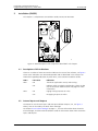
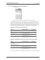
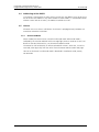
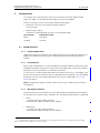
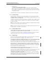
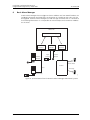
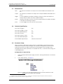
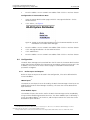
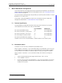
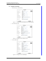
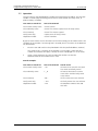
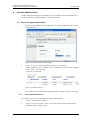
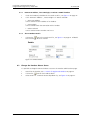
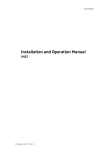
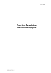
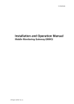
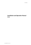
TD 92322GB
Installation and Operation Manual
Integrated Message Server, IMS/IP-WiFi
2007-06-26/ Ver. D
Installation and Operation Manual
Integrated Message Server, IMS/IP-WiFi
TD 92322GB
Contents
1 Introduction............................................................................................................. 1
1.1 Requirements ..................................................................................................... 2
2 Installation (ELISE2)................................................................................................. 3
2.1 Description of LED Indications ............................................................................ 3
2.2 Internal Inputs and Outputs ............................................................................... 3
2.3 Function Indicator and Error Relay Output .......................................................... 4
2.4 Addressing of the IMS/IP .................................................................................... 5
2.5 Licence .............................................................................................................. 5
2.5.1 Unlicensed Mode ....................................................................................... 5
3 Configuration .......................................................................................................... 6
3.1 WLAN Interface ................................................................................................. 6
3.1.1 Handset Registration .................................................................................. 6
3.1.2 Shared Phones ........................................................................................... 6
3.1.3 Message Distribution ................................................................................. 6
3.1.4 Interface Groups ........................................................................................ 7
3.1.5 Handset Administration ............................................................................. 7
3.1.6 WLAN System ............................................................................................ 7
3.1.7 Messaging Tool .......................................................................................... 8
3.1.8 Phonebook ................................................................................................ 8
3.2 900 Interface ..................................................................................................... 8
3.2.1 System 900 Interface ................................................................................. 8
3.2.2 Message Distribution ................................................................................. 9
3.3 Other Parameters ............................................................................................... 9
3.3.1 Status log .................................................................................................. 9
3.3.2 System Activity log ..................................................................................... 9
3.3.3 User Server .............................................................................................. 10
4 IMS/IP Connected to the A-bus without Central Unit ........................................ 10
5 Absence Handling ................................................................................................. 10
5.1 Absence List ..................................................................................................... 10
6 Basic Alarm Manager ............................................................................................ 11
6.1 Nomenclature .................................................................................................. 12
6.2 Technical Specification ..................................................................................... 12
6.3 Parameter Setup .............................................................................................. 12
6.4 Configuration .................................................................................................. 13
6.4.1 Define Inputs and Outputs ....................................................................... 13
6.4.2 Define an Event ....................................................................................... 14
6.5 Backup and Restore ......................................................................................... 14
2007-06-26/ Ver. D
Installation and Operation Manual
Integrated Message Server, IMS/IP-WiFi
TD 92322GB
7 IMS/IP Phonebook Configuration ........................................................................ 15
7.1 Technical Specification ..................................................................................... 15
7.2 Phonebook address .......................................................................................... 15
7.3 Phonebook Setup ............................................................................................ 16
7.3.1 Enter Search result texts ........................................................................... 16
7.3.2 Select Phonebook Database ..................................................................... 16
7.4 Local Phonebook Administration ...................................................................... 16
7.4.1 Update the Local Database ...................................................................... 17
7.4.2 Export the Local Database ........................................................................ 18
7.4.3 Delete the Local Database ........................................................................ 18
7.5 LDAP Parameter Setup ..................................................................................... 19
7.6 Examples of Settings ........................................................................................ 20
7.7 Operation ........................................................................................................ 21
8 Handset Administration ....................................................................................... 22
8.1 Search for Registered Handsets ........................................................................ 22
8.1.1 Save the Search Result list ........................................................................ 22
8.1.2 Remove IP Address, force a Relogin, or Delete a VoWiFi handset .............. 23
8.1.3 Show Handset Details .............................................................................. 23
8.2 Change the Handset Absent Status .................................................................. 23
9 Messaging tool...................................................................................................... 24
10 Phonebook Service and Route2ELISE ................................................................ 25
11 Open Access Protocol.......................................................................................... 25
11.1 Configuration ................................................................................................ 25
12 Related Documents ............................................................................................. 26
Document History ........................................................................................................ 27
Appendix A: IMS/IP and Firewalls........................................................................... 28
Appendix B: Basic Alarm Manager Configuration Examples................................ 29
2007-06-26/ Ver. D
Installation and Operation Manual
Integrated Message Server, IMS/IP-WiFi
1
TD 92322GB
Introduction
This document describes the installation and configuration of IMS/IP-WiFi, the Integrated
Message Server for the VoWiFi system.
The IMS/IP-WiFi is a message server based on the ELISE hardware. It acts as a messaging
gateway and controls messaging and alarm between Ascom messaging systems and the
VoWiFi handsets in the VoWiFi System. The IMS/IP-WiFi also enables creation of messaging
groups in the VoWiFi System and messages can be sent to the VoWiFi handsets via a
browser with an integrated Messaging Tool.
Messaging
Unite System
VoWiFi System
Send
Send
Send
access points
Unite
modules
WiFi Handsets
LAN
IMS/IP - WiFi
(Messaging Gateway)
VoIP Gateway/Gatekeeper
A-b
us
PRI
System 900
Main PBX
001
ISDN
Figure 1. IMS/IP-WiFi connected to the LAN
IMS/IP-WiFi communicates with the Unite System via the LAN and with System 900 via the
A-bus. The Central Unit in System 900 normally acts as the communication controller on
the A-bus, but if IMS/IP-WiFi is configured to control the communication on the A-bus,
then the Central Unit can be excluded.
An application called Basic Alarm Manager is included in the IMS/IP-WiFi. This application
makes it possible to send messages to Pocket Units in the system, or activate outputs in
the system as a reaction to activated inputs, or alarm or user data from Pocket Units in the
system.
A phonebook that can be accessed from the VoWiFi handsets is also included in the
IMS/IP-WiFi.
Phonebook Service is delivered along with the IMS/IP-WiFi. The service gives the same
functionality as the IMS/IP-WiFi Phonebook and is needed for large phonebooks.
Client applications can communicate with the IMS/IP-WiFi over the Local Area Network
(LAN) with help of the Open Access Protocol (OAP).
2007-06-26/ Ver. D
1
Installation and Operation Manual
Integrated Message Server, IMS/IP-WiFi
1.1
TD 92322GB
Requirements
• Microsoft Internet Explorer 6.0™ or later
(only used for installation, administration and IMS/IP Messaging Tool)
Basic licence for IMS/IP
IMS for VoWiFi licence
Additional licences for IMS/IP
OAP licences:
•
•
•
•
Basic messaging (acknowledge included)
Basic messaging, interactive messaging, and user data
Basic messaging and alarm
Basic messaging, interactive messaging, user data, and alarm
2007-06-26/ Ver. D
2
Installation and Operation Manual
Integrated Message Server, IMS/IP-WiFi
2
TD 92322GB
Installation (ELISE2)
LED2
LED3
LED4
LED5
This chapter is a complement to Installation Guide, ELISE2, TD 92232GB.
SW4
LED1
BAT1
1
SW3
8
LED5
LED2
1
SW2
8
J1
6
IC1
J2
J16
5
J22
1
IC24
1
J9
J10
J12
S3
6
J11
4
J6
1
2
J14
J15
LED6
LED7
J16
1
J4
J11
J8
J20
1
J5
4
1
J6
4
1
J12
J13
2
S4 1J242
S5
S1
S2
J14
013
J7
Figure 2. Board description with components described in this chapter.
2.1
Description of LED Indications
There are a number of LEDs on ELISE that indicate the status of the software, see figure 2.
These status indications are software dependent and are described in this chapter. For
information regarding indications by other LEDs, see the ELISE2 Installation Guide.
LED #
LED status
Indication
LED5
ON
The IMS/IP applications are up and running.
OFF
Problems when starting the applications, check the log
files on the IMS/IP Administration web page for more
information.
ON
Paging waiting in queue to A-bus
OFF
No paging in queue to A-bus
LED2
2.2
Internal Inputs and Outputs
The IMS/IP has two internal inputs and two open-collector outputs (J16, see figure 2
above), that can be used by the Basic Alarm Manager.
See chapter 6 Basic Alarm Manager on page 11, for more information about the Basic
Alarm Manager, and the ELISE2 Installation Guide for information about how to connect
inputs and outputs.
2007-06-26/ Ver. D
3
Installation and Operation Manual
Integrated Message Server, IMS/IP-WiFi
2.3
TD 92322GB
Function Indicator and Error Relay Output
003
Function indicator
Figure 3. The function indicator that indicates the status of the IMS/IP
The function indicator and the error relay indicate the status of the IMS/IP. The indication is
dependent of whether the IMS/IP is connected to the A-bus or not, and also whether
there is a Central Unit connected to the A-bus. Which mode the IMS/IP uses is set on the
IMS/IP administration pages, see chapter 3.2.1 System 900 Interface on page 8 for more
information. The function indicator and error relay indications are described below.
IMS/IP connected to A-bus with a Central Unit
Status
Function Indicator
Error Relay
Communication with the Central Green
Unit.
Operates
No communication with the
Central Unit.
Flashing orange
(100ms ON/100 ms OFF)
Released
Shut down
Flashing red
Released
(1000ms ON/3000 ms OFF)
Restart or reboot
Flashing orange
(100ms ON/800 ms OFF)
Released
IMS/IP connected to A-bus without a Central Unit, or A-bus not connected
Status
Function Indicator
Error Relay
A-bus connection or no A-bus
connection.
(Connected or not, it does not
change the indication.)
Green
Operates
Shut down
Flashing red
Released
(1000ms ON/3000 ms OFF)
Restart or reboot
Flashing orange
(100ms ON/800 ms OFF)
Released
For information about other LED indications, see Installation Guide, ELISE2, TD 92232GB.
2007-06-26/ Ver. D
4
Installation and Operation Manual
Integrated Message Server, IMS/IP-WiFi
2.4
TD 92322GB
Addressing of the IMS/IP
If the IMS/IP is connected to an A-bus with a Central Unit, the address must not be set to
00 nor to the same address as any other module. In other modes, i.e. connected to A-bus
without Central Unit or no A-bus, the address should be set to 00.
2.5
Licence
All IMS/IP units must have a valid licence. The licence is preprogrammed, and does not
need to be entered at installation.
2.5.1
Unlicensed Mode
When needed, the IMS/IP can be started in unlicensed mode. Unlicensed mode is
indicated by the Function Indicator with an orange light (3000 ms ON/100 ms OFF). For
details on the LED characteristics, see the ELISE Installation Guide.
The IMS/IP has full functionality in unlicensed mode for 2 hours. After that, it must be
restarted, either physically from the unit or from the IMS/IP Administration web page.
How to set the IMS/IP in unlicensed mode is described in Installation Guide, ELISE2,
TD 92232GB.
2007-06-26/ Ver. D
5
Installation and Operation Manual
Integrated Message Server, IMS/IP-WiFi
3
TD 92322GB
Configuration
This chapter covers the parameters that can be altered on the IMS/IP Administration
pages. The address to the administration pages is xxx.xxx.xxx.xxx/admin.
There are two types of users for the IMS/IP administration pages:
• Technicians, first time set up commissioning (sysadmin)
Full access right.
• Administrators (admin)
Limitation in troubleshooting (no access to view complete log).
3.1
User account
Default password
admin
changeme
sysadmin
setmeup
WLAN Interface
3.1.1
Handset Registration
To be able to register to the IMS/IP, each VoWiFi handset must be programmed with the IP
address of the IMS/IP used, refer to the Configuration Manual for respective VoWiFi
handset.
3.1.2
Shared Phones
When using shared phones it is recommended that all VoWiFi handsets authenticates with
individual passwords. The IMS/IP can retrieve these passwords from a User Server. Another
possibility is to use the handset´s call number as password.
If a User Server is used the operating mode for the UNS must be set to “forwarding” and
the User Server (the ESS which has the users defined) must be specified as the forwarding
destination. The ESS must also be identified as User Server as described in 3.3.3 User
Server on page 10.
Note: Shared phones requires, besides the User Server (ESS), a PDM System version for
management.
3.1.3
Message Distribution
The WLAN Interface has distribution lists that define where incoming data from handsets,
for example alarms and user data, should be sent. The following information is supported:
• Alarm
- Personal alarm from VoWiFi handsets.
The IMS/IP-WiFi adds the handset´s MAC address1.
• Mobile Data
- User data sent from VoWiFi handsets.
The IMS/IP-WiFi adds the handset´s MAC address1.
1. The MAC address is added as extended information in the original sender (USD). In for example the AMS, the MAC
address is found as service address in the source address.
2007-06-26/ Ver. D
6
Installation and Operation Manual
Integrated Message Server, IMS/IP-WiFi
TD 92322GB
• Availability Info
- Change of status of the VoWiFi handsets.
(The status can be changed from the IMS/IP GUI or from the VoWiFi handset).
When an alarm or user key data message is received from a PP, the PP MAC address
shall be added as extended information in the original sender (USD) when the message
is distributed on UNITE.
The addressing of the receivers is described in Installation Guide, ELISE2, TD 92232GB.
3.1.4
Interface Groups
Interface Groups is used when one message should be sent to several VoWiFi handsets.
The group handler has 30 groups with 15 handset addresses and one group with 50. The
first group in the list is the large group.
The groups are defined in the administration pages. Each group is given an address, either
a name or a number, and then the addresses of the handsets that should be included in
the group are added.
Note: Only VoWiFi handsets can be included in the groups in the group handler. Messages
will not be sent to any other types of Pocket Units.
Note: If it shall be possible to send messages from a VoWiFi handset or from the A-bus to
the group address, the address must be numeric.
3.1.5
Handset Administration
Handset Administration gives the possibility to list all handsets that are registered in the
system, search for a specific handset, or a range of handsets.
It is possible to customize the pages by changing the language and number of handsets
shown on the search result list. See 8 Handset Administration on page 22.
3.1.6
WLAN System
WLAN system handles the VoWiFi handset relogin time and authentication. Call diversion
display text and Extended activity logging is also enabled in this view.
The time before a handset must relogin to the IMS/IP is set in minutes and when this time
is exceeded the handset will be considered unreachable. This is the maximum time it takes
for a handset to reconnect after installing a new IMS/IP, or updating an IMS/IP.
Note that a short relogin time implies a higher service/security but it also loads the system.
Text specified in the “Call Diversion Display Text” text field is, if enabled, added to the
display text when a call diversion takes place. By entering the character “%”, the original
call ID will be included in the display text on the place where the character is entered. Note
that all characters are not possible to display.
Enable Extended Activity Log for intermediate logs, for more information refer to the
Function Description, Activity Logging in Unite, TD 92341GB.
The very first time a VoWiFi handset logs in to the IMS/IP, it must authenticate itself to the
IMS/IP with a password. The password is then stored in the handset for future
authentication. The IMS/IP has three authentication alternatives; “Common password”,
“User server” and “Number as password”.
A common password can be specified in the IMS/IP, and this password is then used for all
VoWiFi handsets in the system. If the common password field is left empty, the handset
must send an empty password for authentication.
2007-06-26/ Ver. D
7
Installation and Operation Manual
Integrated Message Server, IMS/IP-WiFi
TD 92322GB
If individual passwords is needed, for example for shared phones, passwords can either be
specified in a User Server or the individual call numbers can be used, refer to 3.1.2 Shared
Phones.
Forced login allows a user to login with a call number that already is in use. The handset
that already is logged in will then be unregistered.
The function is only valid when the authentication method is set to “Common password”
or to “Number as password”.
3.1.7
Messaging Tool
The title on the IMS/IP Messaging Tool web page can be changed.
3.1.8
Phonebook
Included in the IMS/IP is the possibility to access and search for phone numbers in a
phonebook, from a VoWiFi handset. The phone numbers can be searched for in a local
database or in an LDAP server. Refer to chapter 7 IMS/IP Phonebook Configuration on
page 15 for configuration instructions.
3.2
900 Interface
This chapter handles settings for the connection to the System 900 A-bus. If the A-bus is
not connected, the bus operating mode should be set to ‘No A-bus’. All other parameters
only needs to be set when the IMS/IP is connected to a Central Unit in the System 900, or
controlling the communication on the A-bus in systems without a Central Unit.
3.2.1
System 900 Interface
• Bus operating mode
- A-bus with Central Unit: The IMS/IP is connected to a system with a Central Unit.
- A-bus without Central Unit: The IMS/IP controls the communication on the A-bus.
- According to DIP switch: If the IMS/IP address DIP switch is set to 00, it is controlling
the communication on the A-bus. If the address is set to 01-FF the Central Unit is
controlling the communication on the A-bus.
- No A-bus connected: The A-bus connection is not used. If the IMS/IP expects an Abus with Central Unit, the IMS/IP will indicate “starting up”.
• Module Priority
This is the IMS/IP priority on the A-bus. This parameter is only used when the IMS/IP is
connected to an A-bus with Central Unit.
• Number of message transmissions
This is how many times a paging is transmitted in the System 900. This parameter is
only used when the IMS/IP is connected to an A-bus with Central Unit.
• Configuration of parameters below
When the IMS/IP is connected to an A-bus with Central Unit, the parameters in the
Central Unit can be used and this parameter can be set to “automatic”. If the IMS/IP is
controlling the communication on the A-bus, the parameters have to be configured
manually.
• Number of digits in call number
This is the number of digits in the pocket unit addresses in the system. If the IMS/IP is
controlling the communication on the A-bus, this parameter has to be set manually.
See System Planning, On-site Paging System, TD 90202GB for more information.
• Prefix and call number range
This is the prefix that is used in the system. The prefix has to be the same as for the
other modules in the system. If the IMS/IP is controlling the communication on the A-
2007-06-26/ Ver. D
8
Installation and Operation Manual
Integrated Message Server, IMS/IP-WiFi
TD 92322GB
bus, this parameter has to be set manually. See System Planning, On-site Paging
System, TD 90202GB for more information.
• Send module status from A-bus to Unite
The IMS/IP can send module status received from the A-bus to the Unite system. This
also means that if IMS/IP is connected as slave it will subscribe for module status from
the central unit in system 900.
• Call diversion display text
Text specified here is added to the display message at a call diversion. The originating
Call ID can be included by writing a “%” character where the Call ID shall be inserted
in the text.
3.2.2
Message Distribution
The 900 Interface has distribution lists that define where incoming data from the Pocket
Units in the System 900 and the System 900 modules should be sent. The receivers are
addressed in the same way as for the DECT Interface that is described in Installation
Guide, ELISE2, TD 92232GB. The following information is supported:
• Alarm
- Personal alarms with location information from Pocket Units.
• Mobile Data
- Data sent from Pocket Units.
• Input activity
- An input on an Alarm Module has been activated.
• Location
- Special Location1 information from Pocket Units.
• Availability Info
- Includes absence information, i.e. if a Pocket Unit is placed in Charging/Storage
Rack.
Pagings that are received from the A-bus will be transmitted to the destination that
corresponds to the address in the UNS.
3.3
Other Parameters
3.3.1
Status log
The Status log messages have their own distribution list that can be reached from
System Setup > Other > Logging > Status log. The status log messages include
information about errors in applications or modules, for example module status from Fixed
Units on the A-bus. For information about how to address the receiver of the Status log
messages, see Installation Guide, ELISE2, TD 92232GB.
3.3.2
System Activity log
The System Activity log messages have their own distribution list that can be reached from
System Setup > Other > Logging> System Activity log. For information of system activity
log messages, see Function Description, Activity Logging in Unite, TD 92341GB. For
information about how to address the receiver of the System Activity log messages, see
Installation and Operation Manual, Enhanced System Services, ESS, TD 92253GB.
1.The Special Location can be sent every time a pocket unit gets a new location from a locator in the system. This requires
configuration both in the handset and in the locator. Also called “Immediate Alarm Transmission”.
2007-06-26/ Ver. D
9
Installation and Operation Manual
Integrated Message Server, IMS/IP-WiFi
3.3.3
TD 92322GB
User Server
IMS/IP can use an ESS as a user server for authentication of portables, see 3.1.6 WLAN
System on page 7.
4
1
Select System Setup > User Server on the IMS/IP administration page.
2
Enter the IP address of the ESS which has users defined and click “Activate”.
IMS/IP Connected to the A-bus without Central Unit
To be able to connect the System 900 modules to the VoWiFi System without using a
Central Unit, the IMS/IP can control the communication on the System 900 A-bus. This can
be used when, for example, an Alarm Module or Output Module is connected to the
system.
5
Absence Handling
The IMS/IP keeps track of all handsets that have reported absence status. The handset can
report unavailable if it is set in Manual Absent mode from the IMS/IP GUI, see 8.2 Change
the Handset Absent Status on page 23, or from the Profiles menu in the Handset, see the
User Manual for the handset.
When a message is sent to an absent handset, the sending module can get information
from the IMS/IP that the handset is absent. Changes in the handset status, which include
availability information, can also result in a message to modules in the distribution list, see
3.1.3 Message Distribution on page 6.
5.1
Absence List
If a search is performed from the IMS/IP GUI (WLAN interface > Handset Administration) a
list indicating the handsets status is presented. Different status criteria can be used in the
search. Another possibility is to list all handsets and then sort in the search result list with
desired status.
2007-06-26/ Ver. D
10
Installation and Operation Manual
Integrated Message Server, IMS/IP-WiFi
6
TD 92322GB
Basic Alarm Manager
A Basic Alarm Manager that can trigger on alarms and data sent from VoWiFi handsets are
included in the IMS/IP. Activated inputs on the IMS/IP or a module on the A-bus can also
be triggered. The Basic Alarm Manager can send messages to Pocket Units as a reaction to
the incoming information. It is also possible to activate outputs on the IMS/IP or modules
on the A-bus.
IMS / IP
Basic Alarm Manager
900
Interface
WLAN
Interface
I/O
Handler
IMS Inputs
Input
Activity
Activate
Output
IMS Outputs
Activate
Output
Alarm
Mobile Data
VoWiFi
A-bus
Message
009
Input Activity
Figure 4. Communication flow for the Basic Alarm Manager and external systems.
2007-06-26/ Ver. D
11
Installation and Operation Manual
Integrated Message Server, IMS/IP-WiFi
6.1
6.2
6.3
TD 92322GB
Nomenclature
Input
An input on the IMS/IP or an input on an Alarm Module connected to the Abus.
Output
An output on the IMS/IP or an output on an Output Module connected to the
A-bus.
Trigger
A set of conditions that detects whether an input has been activated, or an
alarm or data has been sent from a VoWiFi handset.
Action
Sending a message to a Unite Call ID for example Pocket Unit address included
in the UNS or activating an output.
Event
A set of triggers that starts one or several actions.
Technical Specification
Max. No. of triggers:
250
Max. No. of triggers / event:
10
Max. No. of defined inputs:
250
Max. No. of actions:
250
Max. No. of actions / event:
10
Max. No of defined outputs:
250
Alarm Module requirements:
Software version 4.00 1
Parameter Setup
When the IMS/IP is delivered, the 900 Interface is configured to send all Input Activity
information to the Basic Alarm Manager. The interface is configured to send all Alarms
and User Data from the handset to the Basic Alarm Manager. These settings can be
changed when the IMS/IP parameters are restored from file, i.e. check that the settings are
as described below.
Configuration of Input Activity1
1
Open the IMS/IP administration pages and click “Message Distribution” for the 900
Interface.
2
Click “Input Activity”, see figure 5.
Figure 5. Setting up the Message Distribution list for the 900 Interface to send
information to the Basic Alarm Manager.
1.From this version the Alarm Module can be configured to send Input Activity information both when the input is
opened and closed. Previous versions have no support for this.
2007-06-26/ Ver. D
12
Installation and Operation Manual
Integrated Message Server, IMS/IP-WiFi
3
TD 92322GB
Enter the address 127.0.0.1/BAM in one address field. Click the “Activate” button.
Configuration of Alarm and User Data
1
Open the IMS/IP administration pages and click “Message Distribution” for the
WLAN Interface.
2
Click “Alarm”, see figure 6.
Figure 6. Setting up the Message Distribution list for the WLAN Interface to send
information to the Basic Alarm Manager.
6.4
3
Enter the address 127.0.0.1/BAM in one address field. Click the “Activate” button.
4
Click “Message Distribution” for the WLAN Interface.
5
Click “Mobile Data”.
6
Enter the address 127.0.0.1/BAM in one address field. Click the “Activate” button.
Configuration
The Basic Alarm Manager can be reached from the left menu in the IMS/IP administration
pages and also from the direct link http://xxx.xxx.xxx.xxx/bam, where xxx.xxx.xxx.xxx is the
IP address. The user that has access to these pages is called admin and the default
password is changeme.
6.4.1
Define Inputs and Outputs
Before an input or output can be used in the configuration, it has to be defined with a
name and address.
IMS/IP inputs1
The IMS/IP has two inputs that can be used by the Basic Alarm Manager. These inputs are
predefined in the Basic Alarm Manager at delivery. The states that can be detected are
open and close.
Alarm Module inputs
The number of inputs that can be used in the Basic Alarm Manager can be extended by
using an Alarm Module connected to the A-bus. The Alarm Module input is defined by a
name, the module address2 on the A-bus, and the input number. The states that can be
detected are open and close.
1.The IMS/IP has two inputs. When the input is activated, it is called ‘close’ in the Basic Alarm Manager. For more
information about the inputs, see the ELISE Installation Guide.
2.Every module that is connected to the A-bus has a two digit hexadecimal address that is set with a DIP switch.
2007-06-26/ Ver. D
13
Installation and Operation Manual
Integrated Message Server, IMS/IP-WiFi
TD 92322GB
IMS/IP outputs1
The IMS/IP has two outputs that can be used by the Basic Alarm Manager. These outputs
are predefined in the Basic Alarm Manager at delivery. The initial state, i.e. high or low, for
the output can also be set from the Basic Alarm Manager.
Output Module outputs
The number of outputs that can be used in the Basic Alarm Manager can be extended by
using an Output Module connected to the A-bus. The Output Module output is defined
by a name, the module address on the A-bus, and the output number. The initial state, i.e.
high or low, for the output can also be set from the Basic Alarm Manager.
6.4.2
Define an Event
An Event consists of one or several trigger conditions that leads to one or several actions.
It is indicated in the left menu how many triggers and actions that has been configured.
See also configuration examples in Appendix B.
Triggers
A trigger is a set of conditions that have to be fulfilled, for example that an input has to be
open for a certain time period or that an alarm has been sent from a handset.
Several triggers can be defined for each Event. The actions in the Event will be carried out
when any of the triggers is fulfilled.
Actions
The actions that can be carried out by the Basic Alarm Manager is to send a message to a
Pocket Unit in the system or activate an output. The UNS will be used to get the
destination address corresponding to the address entered in the “Handset No.” field.
Several actions can be carried out for each event. The actions can be repeated at a regular
time interval as long as an input is active.
6.5
Backup and Restore
The Basic Alarm Manager can be backed up and restored from the Basic Alarm Manager
user interface. The configuration of the Basic Alarm Manager will also be included in the
backup that is created from the IMS/IP administration pages.
Note: When the IMS/IP is restored from the administration pages, the Basic Alarm
Manager will also be restored, i.e. all changes that have been made since the last backup
will be discarded.
It is also possible to clear the complete configuration from the Basic Alarm Manager user
interface.
1.The IMS/IP has two outputs of open-collector type. When the output is active, it is called ‘low’ in the Basic Alarm
Manager. For more information about the outputs, see the ELISE Installation Guide.
2007-06-26/ Ver. D
14
Installation and Operation Manual
Integrated Message Server, IMS/IP-WiFi
7
TD 92322GB
IMS/IP Phonebook Configuration
This chapter describes the configuration of the internal IMS/IP Phonebook. For information
about installation and configuration of the Phonebook Service, see 10 Phonebook Service
and Route2ELISE on page 25.
The internal IMS/IP Phonebook gives the possibility to search for phone numbers in a local
database or in an LDAP server.
If the search is to be forwarded to an LDAP server, the LDAP parameters need to be
configured as described in 7.5 LDAP Parameter Setup on page 19.
7.1
Technical Specification
The local database has defined limitations while most of the limitations for the LDAP
server depends on the LDAP server used, see table below. 1
Local Database
LDAP Server
Max. No. of phonebook entries:
500
Server dependent
Max. No. of characters in family name:
20
Server dependent
Max. No. of characters in first name:
20
Server dependent
Max. No. of digits in phone number:
20
Server dependent
25
25
Max. No. of returned entries / request:
1
Handsets that can access the phonebook:
7.2
VoWiFi handsets in the VoWiFi system
Phonebook address
The default Call ID in the UNS is 999999 for phonebook access.
When the UNS in the IMS/IP is set to forwarding mode, the phonebook Call ID must exist
in the module that the requests are sent to. Any change of the Call ID and/or IP address
must be made in that module. If the default address is used, no changes are needed.
When the UNS in the IMS/IP is set to stand-alone mode, do as follows to change the
address:
1
Open the IMS/IP administration pages and click UNS > Alias / Call ID.
2
Click “999999” in the list.
3
Enter the new Call ID for the phonebook, i.e. the Call ID the handsets are using to
access the phonebook. Check that the Call ID does not conflict with any of the
handsets in the system.
1.See also documentation for the handset.
2007-06-26/ Ver. D
15
Installation and Operation Manual
Integrated Message Server, IMS/IP-WiFi
7.3
TD 92322GB
Phonebook Setup
Figure 1.
Figure 7. IMS/IP Phonebook
7.3.1
Enter Search result texts
When a request is sent to the phonebook, a text is included in the response that is sent to
the handset. These texts can be customized, for example translated.
1
Open the IMS/IP administration pages and click “Phonebook”.
2
Enter the texts that should be included in the search result, see table below for
more information about the different texts and when they are used.
7.3.2
Default text
Description
Search result
Included in a successful request before the entries that
matched the request
Sorry, no match
Sent when there were no match for the sent request.
Select Phonebook Database
Select which database to use for phone numbers; “Local” database, or “LDAP” server.
• If the default local database is selected, continue below in chapter 7.4 Local
Phonebook Administration.
• If LDAP server is selected, continue in chapter 7.5 LDAP Parameter Setup on page 19.
7.4
Local Phonebook Administration
The local phonebook database is administrated from a web browser. The administration
can be reached from the page xxx.xxx.xxx.xxx/user, where xxx.xxx.xxx.xxx is the IMS/IP
address. A special user with login name user has access to this page. It is also possible to
change the password for this user from this page.
2007-06-26/ Ver. D
16
Installation and Operation Manual
Integrated Message Server, IMS/IP-WiFi
7.4.1
TD 92322GB
Update the Local Database
The phonebook entries can be created from any CSV file and also from the web interface.
Import a CSV file
The CSV file can be created using Microsoft Excel or any leading spreadsheet or relational
database, and should have the following format:
First name 1;Family name 1;Phone number 1
First name 2;Family name 2;Phone number 2
The CSV file is imported as described below.
1
Open the page: http://xxx.xxx.xxx.xxx/user.
Log on with user. The default password is password.
2
Click the Administrate IMS/IP Phonebook link.
3
Click the “Import/Export” button.
The window shown in figure 8 will appear.
Figure 8. Importing a CSV file.
4
Click “Browse” to locate the CSV file in the file system. Click “Import file”.
Update the local database from the web interface
1
Open the page: http://xxx.xxx.xxx.xxx/user.
Log on with user. The default password is password.
2
Click the Administrate IMS/IP Phonebook link
The window shown in figure 9 will appear.
Figure 9. Web interface for updating the phonebook database.
3
Click “Add new entry”. Enter “First name”, “Family name”, and “Number”. If the
field is not filled in or if the entered value is not valid, the field is coloured yellow.
4
When all entries have been added, click “Save changes”.
5
Click the “Edit” button to return to the window in figure 9.
2007-06-26/ Ver. D
17
Installation and Operation Manual
Integrated Message Server, IMS/IP-WiFi
7.4.2
TD 92322GB
Export the Local Database
The phonebook database can be exported to a CSV file for editing and backup reasons.
1
Open the page: http://xxx.xxx.xxx.xxx/user.
Log on with user. The default password is password.
2
Click the Administrate IMS/IP Phonebook link.
The window shown in figure 10 will appear.
Figure 10. Exporting a CSV file.
3
7.4.3
Click “Export file”. Select “Save this file to disk”. Enter a file name and the location
where the file should be stored and click “Save”.
Delete the Local Database
1
Open the page: http://xxx.xxx.xxx.xxx/user.
Log on with user. The default password is password.
2
Click the Administrate IMS/IP Phonebook link.
The window shown in figure 10 will appear.
3
Click “Delete phonebook”. Click “OK” in the dialogue window that appears.
2007-06-26/ Ver. D
18
Installation and Operation Manual
Integrated Message Server, IMS/IP-WiFi
7.5
TD 92322GB
LDAP Parameter Setup
The Lightweight Directory Access Protocol (LDAP) is an application protocol for querying
and modifying directory services running over TCP/IP. The IMS/IP starts an LDAP session by
connecting to an LDAP server. The IMS/IP then sends operation requests to the server, and
the server sends responses in return.
An LDAP directory is a tree of directory entries and follows the structure below:
• An entry consists of a set of attributes.
• An attribute has a name and one or more values.
Figure 2. Each entry has a unique name; the distinguished name (DN). DN consists of its relative distinguished name (RDN) constructed from some attribute(s) in the entry, followed by the parent entry's DN. Think of the DN as a full filename and the RDN as a relative filename in a folder.
An entry can look like this:
dn: cn=John Ericson,dc=company,dc=com
cn: John Ericson
givenName: John
sn: Ericson
telephoneNumber: +1 888 555 6789
Figure 3. mail: [email protected]
dn is the name of the entry; it is not an attribute nor part of the entry. “cn=John
Ericson” is the entry's RDN, and “dc=company, dc=com” is the DN of the parent entry.
The other lines show the attributes in the entry. Attribute names are typically
mnemonic strings, like “cn” for common name, “dc” for domain component, “mail”
for e-mail address and “sn” for surname. See 7.6 Examples of Settings on page 20.
Figure 4.
1
Click on the View LDAP parameters link.
2
Enter the IP or DNS address to the LDAP server in the LDAP Server Address field.
3
Enter the port number used by the LDAP server in the Port Number field.
4
Select how to authenticate to the LDAP server in the Authentication Method drop
down list.
Note: If the authentication method “SASL/DIGEST-MD5” is selected, the IP address for
primary DNS server must be entered in the DNS server field on the Network. Otherwise it is
not possible to authenticate with the LDAP directory Microsoft Active Directory 2003.
5
Enter the user name used for logging on to the LDAP server in the User name field.
6
Enter the password used for logging on to the LDAP server in the Password field.
7
Enter the user entries' parent DN in the Search Base DN field.
(The distinguished name for all users common entry.)
8
Enter the name of the attribute that holds the phone numbers in the Number
attribute field.
9
Select the appropriate option in the Type of Name Attribute(s) drop down list.
The option depends on if the name is stored in a single attribute or if it is splitted
into two different attributes.
10
Enter name(s) of the attribute(s) containing first name and family name in the Name
Attribute(s) field. If two attributes are used, enter the first name on the first line and
the family name on the second line.
11
Enter an error message to be sent as an answer to a phonebook query that was
unsuccessful in the Error message field.
2007-06-26/ Ver. D
19
Installation and Operation Manual
Integrated Message Server, IMS/IP-WiFi
7.6
TD 92322GB
Examples of Settings
• LDAP directory in VoIP Gateway
Figure 5. i
Figure 11. Settings for the LDAP directory in the VoIP Gateway
• Active directory 2003
Figure 6.
Figure 12. Settings for Active directory 2003
• Cisco CallManager
Figure 7.
Figure 13. Settings for Cisco CallManager
2007-06-26/ Ver. D
20
Installation and Operation Manual
Integrated Message Server, IMS/IP-WiFi
7.7
TD 92322GB
Operation
The user accesses the phonebook by sending a message from the handset. The message
includes a search query containing part of the first name and/or the family name, or
phone number, see below.
You want to search for:
Text to be entered:
First name or Family name
<Part of name>
First and Family name
<Part of first name><space><Part of family name>
First name only
<Part of first name><space>
Family name only
<space><Part of family name>
Telephone number
<Part of number>
By part of name means the first characters of the name and by part of number means the
last digits of the number. If no message text is entered, the 25 first entries in the database
will be returned.
1
Enter the text and send it to the phonebook with the specified address (number).
The search result is sent back to the handset as an message. If more than one
number that matches the query is found, the result is displayed as a list of names.
2
Select a name and press the Call key to dial the number. See also the
documentation for the handset that is used.
Search examples
Text to be entered:
Search result:
First name or Family name
SM
All names that start with Sm, both
first names and family names.
First and Family name
L
All entries where the first name
starts with L and the family name
starts with B.
First name only
AN
[
B
Family name only
[
[
You want to search for:
Telephone number
200
2007-06-26/ Ver. D
AN
All first names that starts with An.
All family names that start with An.
All telephone numbers that end
with 200.
21
Installation and Operation Manual
Integrated Message Server, IMS/IP-WiFi
8
TD 92322GB
Handset Administration
Handset Administration gives the possibility to list all handsets that are registered in the
system, search for a specific handset or a range of handsets
8.1
Search for Registered Handsets
1
Open the IMS/IP administration pages and click “Handset Administration” for the
WLAN Interface.
Figure 14. Handset Administration pages.
2
Select “List All” or search with different criteria, for example the
“Address/Number”, the “IP address”, the “Hardware ID” (often the MAC address)
or the “Status” of the handset.
A result list is presented.
Figure 15. Search result list.
The search result can be sorted by address/number, IP address, status or last login.
8.1.1
Save the Search Result list
The search result list can be exported to a comma separated file.
1
Click the “Export Result” button.
2
Select “Save this file to disk”. Enter a file name and the location where the file
should be stored, and click “Save”.
2007-06-26/ Ver. D
22
Installation and Operation Manual
Integrated Message Server, IMS/IP-WiFi
8.1.2
TD 92322GB
Remove IP Address, force a Relogin, or Delete a VoWiFi handset
1
Check the handset(s) checkbox in the search result list, see figure 15 on page 22
2
Click “Remove IP Address”, “Force Relogin” or “Delete Selected”.
• Remove IP Address
Can be used to reset the address of an handset.
• Force Relogin
Can be used to check the connection with a handset.
• Delete Selected
Can be used to remove numbers not in use.
8.1.3
Show Handset Details
1
Click on the
icon in the search result list, see figure 15 on page 22. All details
of the chosen handset are viewed.
Figure 16. Handset details.
8.2
Change the Handset Absent Status
It is possible to change the Manual Absent status on the Handset administration pages.
1
Search for the handset, see 8.1 Search for Registered Handsets on page 22.
2
Click on the
3
Select on/off in the Manual Absent drop-down list, see figure 16 on page 23.
2007-06-26/ Ver. D
icon to view handset details.
23
Installation and Operation Manual
Integrated Message Server, IMS/IP-WiFi
9
TD 92322GB
Messaging tool
A web-based messaging tool that can be used to send messages to handsets is included in
the IMS/IP. The tool is opened when the IP address or DNS name is entered in the browser’s
address field, and can be used to send messages with predefined priority and beep
characteristics to Pocket Units. The figure below describes how to use the messaging tool.
The title of the tool can be customized on the IMS/IP administration pages, see 3.1.7
Messaging Tool on page 8 for more information.
Figure 17. The IMS/IP messaging tool
Enter the call number of a Pocket Unit or the address of a group (1). Enter the message
text that should be sent to the handset (2). Click the “Send” button (3).
A pop-up window indicates whether the message has been sent or not.
Figure 18. Message sent and not sent.
If the message has not been sent, try to send the message again. Possible errors are:
• No address
• Licence error
2007-06-26/ Ver. D
24
Installation and Operation Manual
Integrated Message Server, IMS/IP-WiFi
10
TD 92322GB
Phonebook Service and Route2ELISE
A CD with Phonebook Service and Route2ELISE is included in the IMS/IP delivery.
For more information about the Phonebook Service and how to install it, see
documentation included on the CD and also Installation and Operation Manual,
Phonebook Service.
Route2ELISE is used during the installation. See Installation Guide, ELISE for more
information.
11
Open Access Protocol
The IMS/IP has a server that client applications can use to communicate with the systems
that the IMS/IP is connected to, for example the VoWiFi System or System 900. The
protocol that is used for communication is called Open Access Protocol (OAP), and
therefore the server is called OAP Server.
See Function Description, Open Access Protocol, TD 92215GB for more information about
the protocol and when it can be used.
11.1 Configuration
The Message Distribution lists for the different interfaces have to be configured to send
the information to the OAP Server, in order to give the client access to the information.
The address of the OAP Server is xxx.xxx.xxx.xxx/OAP.
Configuration Example
The Interface should be configured to send User Data to the OAP Server.
1
Open the IMS/IP administration pages and click “Message Distribution” for the
Interface.
2
Click “Mobile Data”, see figure 19.
Figure 19. Setting up the Message Distribution list for the Interface to send
information to the OAP Server.
3
2007-06-26/ Ver. D
Enter the address 127.0.0.1/OAP in one of the address fields. Click the “Activate”
button.
25
Installation and Operation Manual
Integrated Message Server, IMS/IP-WiFi
12
TD 92322GB
Related Documents
Data Sheet, Integrated Message Server IMS/IP - WiFi
TD 92321GB
Installation Guide, ELISE2
TD 92232GB
Function Description, Open Access Protocol
TD 92215GB
Function Description, Activity Logging in Unite
TD 92341GB
Installation and Operation Manual, Phonebook Service
TD 92360GB
Installation and Operation Manual, Enhanced System Services, ESS TD 92253GB
Installation Guide, T941AM8 Alarm Module
TD 90858GB
Installation Guide, T941AM32 Alarm Module
TD 90854GB
Installation Guide, T942SI Serial Interface
TD 90927GB
Installation Guide, T941OM Output Module
TD 90859GB
System Installation, On-site Paging System
TD 90227GB
System Planning, On-site Paging System
TD 90202GB
System Installation, Personal Security System
TD 90678GB
General Description, PCPAR
TD 90799GB
Installation Guides of Interface Modules included in System 900
2007-06-26/ Ver. D
26
Installation and Operation Manual
Integrated Message Server, IMS/IP-WiFi
TD 92322GB
Document History
For details in the latest version, see change bars in the document.
Version
Date
A
2006-02-13 First released version
B
2006-03-06 Authentication information in 3.1.6 WLAN System on page 7,
and new chapter 3.3.3 User Server on page 10.
C
2007-02-14 New chapter 3.1.2 Shared Phones on page 6.
D
2007-06-26 • New parameter information; authentication method, forced
login and call diversion display text, added to 3.1.6 WLAN
System on page 7.
• Parameter settings for LDAP in 7.5 LDAP Parameter Setup on
page 19.
2007-06-26/ Ver. D
Description
27
Installation and Operation Manual
Integrated Message Server, IMS/IP-WiFi
TD 92322GB
Appendix A: IMS/IP and Firewalls
If an application or unit has to communicate through a firewall with the IMS/IP,
communication has to be permitted on the ports that are used. The following applies:
Port
Application or unit
Transport protocol
80
Web configuration of the IMS/IP
TCP
123
Network Time Protocol (NTP)
UDP
3217
Other Unite compliant units
UDP
2775
Phonebook Service
UDP
1321
OAP Server
TCP
1322
OAP Server
TCP
10101
Remote connection
TCP
33000
Handset communication
TCP
389
Lightweight Directory Access Protocol (LDAP)
TCP
2007-06-26/ Ver. D
28
Installation and Operation Manual
Integrated Message Server, IMS/IP-WiFi
TD 92322GB
Appendix B: Basic Alarm Manager Configuration Examples
System Components
1 Alarm Module, 1 inputs has been defined in the Basic Alarm Manager.
Input names: Cold-storage room 1
1 Output Module, 2 outputs have been defined in the Basic Alarm Manager.
Output names: Lamp cold-storage 1, Siren
4 Handsets with push-button, no-movement, man-down, and pull-cord alarms.
Handset addresses: 1440, 1441, 1442, and 1443
The addresses of the handsets are included in the UNS number plan.
Example 1
A push-button alarm (double press) is received from 1440. A message is sent to the other
handsets and a siren starts to sound. The alarm is cancelled by sending the data 1440 and
then the siren stops.
Two events are created. One that handles the push-button alarm called “Push-button
alarm from 1440” and one that handles the cancellation called “Alarm cancellation”.
Push-button alarm from 1440
Alarm from Handset Trigger
Handset No.
Type
1440
Push-button double press
Send Message Actions
Handset Address Message text
Beep code
1441
Alarm from 1440
5
1442
Alarm from 1440
5
1443
Alarm from 1440
5
Activate Output Action
Output
Activation Duration
Siren
High
–
The duration is not defined which means that the siren will sound until another action is
started.
Alarm cancellation
Data from Handset Trigger
Handset No.
Data
–
1440
It doesn’t matter which handset that sends the data so the trigger is general when it
comes to handset number.
2007-06-26/ Ver. D
29
Installation and Operation Manual
Integrated Message Server, IMS/IP-WiFi
TD 92322GB
Activate Output Action
Output
Activation Duration
Siren
Low
–
The output is set to the initial state again.
Example 2
When the door to one of the cold-storage rooms is opened, the input “Cold-storage room
1” is closed. If the door is open longer than 2 minutes a message is sent and lamp above
the door is lit. Another message is sent after 10 minutes if the door still is open. After 30
minutes another message is sent and the siren starts to sound. When the door is closed
the siren and lamp is turned off.
Cold-storage room 1, door open
Input Trigger
Input
Activation Activation Repetition Max. No. of
time (s)
time (s)
Repetitions
Cold-storage room 1 Close
120
–
100
When the door has been open for 2 minutes (120 seconds), the action is started. The
action should not be repeated so the “Repetition time” is not stated, and then the value in
the “Max. No. of Repetitions” field has no meaning.
Send Message Actions
Handset Address
Message text
Beep code
1440
Cold-storage room 1,
door is open
2
Activate Output Action
Output
Activation Duration
Lamp cold-storage 1 High
–
The duration is not defined which means that the lamp will be lit until another action is
started.
Cold-storage room 1, door open reminder
Input Trigger
Input
Activation Activation Repetition Max. No. of
time (s)
time (s)
Repetitions
Cold-storage room 1 Close
600
–
100
When the door has been open for 10 minutes (600 seconds), another message should be
sent.
2007-06-26/ Ver. D
30
Installation and Operation Manual
Integrated Message Server, IMS/IP-WiFi
TD 92322GB
Send Message Actions
Handset Address
Message text
Beep code
1440
Cold-storage room 1,
door still open
4
Cold-storage room 1, door open very long
Input Trigger
Input
Activation Activation Repetition Max. No. of
time (s)
time (s)
Repetitions
Cold-storage room 1 Close
1800
–
100
When the door has been open for 30 minutes (1800 seconds), the message is sent to all
handsets and the siren starts to sound.
Send Message Actions
Handset Address
Message text
Beep code
1440
Cold-storage room 1,
door still open
6
1441
Cold-storage room 1,
door is open
4
1442
Cold-storage room 1,
door is open
4
1443
Cold-storage room 1,
door is open
4
Activate Output Action
Output
Activation Duration
Siren
High
–
The duration is not defined which means that the siren will sound until another action is
started.
Cold-storage room door closed
Input Trigger
Input
Activation Activation Repetition Max. No. of
time (s)
time (s)
Repetitions
Cold-storage room 1 Open
0
–
100
When the door closes the actions should be started directly.
Activate Output Actions
Output
Activation Duration
Siren
Low
–
Lamp
Low
–
The outputs are set to the initial state again.
2007-06-26/ Ver. D
31