1
Touch System
Programmer's
Guide
CARROLL TOUCH
TOUCH PRODUCTS
an AMP company
Touch System
Programmer’s
Guide
CARROLL TOUCH
TOUCH PRODUCTS
an AMP company
August 1996
Part #: 2970-0011-01-Rev A
Copyright
Copyright ©1996 Carroll Touch. All rights reserved.
Trademarks
Smart-Frame is a trademark of Carroll Touch, Round Rock, Texas.
IBM and PC are trademarks of International Business Machines
Corporation.
All other brands and product names are trademarks of their respective
owners.
Disclaimer
Carroll Touch has a policy of continually improving products as new
technology becomes available. Carroll Touch reserves the right to make
changes and improvements to the specifications of this equipment at
any time without notice.
Carroll Touch has made every attempt to ensure that the information in
this document is accurate and complete. Carroll Touch assumes no
liability for any damages that result from the use of this manual or the
equipment it documents. Carroll Touch reserves the right to make
changes to this document at any time without notice.
CARROLL TOUCH
Table of Contents
Table of Contents
Welcome . . . . . . . . . . . . . . . . . . . . . . . . . . . . . . . . . . . . .xi
Purpose . . . . . . . . . . . . . . . . . . . . . . . . . . . . . . . . . . . . . . . . xi
Audience . . . . . . . . . . . . . . . . . . . . . . . . . . . . . . . . . . . . . . . xi
Organization . . . . . . . . . . . . . . . . . . . . . . . . . . . . . . . . . . . . xi
Conventions . . . . . . . . . . . . . . . . . . . . . . . . . . . . . . . . . . . . xiii
1. Introduction to Infrared Touch Systems . . . . . . . 1-1
Overview . . . . . . . . . . . . . . . . . . . . . . . . . . . . . . . . . . . . . .
Touch Frames . . . . . . . . . . . . . . . . . . . . . . . . . . . . . . . . . .
Touch Controller . . . . . . . . . . . . . . . . . . . . . . . . . . . . . . . .
Interpolating Touch Coordinates . . . . . . . . . . . . . . . . . . . .
Reporting Touch Coordinates . . . . . . . . . . . . . . . . . . . . . .
Failed Beams . . . . . . . . . . . . . . . . . . . . . . . . . . . . . . . . . . .
Criteria for Failing a Beam . . . . . . . . . . . . . . . . . . . . .
Failed Beam Timing Parameters . . . . . . . . . . . . . . . . .
Criteria for Unfailing a Beam . . . . . . . . . . . . . . . . . . .
Failed Beam Reports . . . . . . . . . . . . . . . . . . . . . . . . . .
1-2
1-2
1-2
1-3
1-4
1-4
1-5
1-5
1-7
1-7
2. Introduction to Guided Wave Touch Systems . . . 2-1
Overview . . . . . . . . . . . . . . . . . . . . . . . . . . . . . . . . . . . . . .
Touch Screens . . . . . . . . . . . . . . . . . . . . . . . . . . . . . . . . . .
Touch Controllers . . . . . . . . . . . . . . . . . . . . . . . . . . . . . . .
EEPROM File and Parameters . . . . . . . . . . . . . . . . . . . . .
2-2
2-2
2-2
2-3
3. General Programming Issues . . . . . . . . . . . . . . . . 3-1
Hardware Configurations . . . . . . . . . . . . . . . . . . . . . . . . . 3-2
Built-In Controllers . . . . . . . . . . . . . . . . . . . . . . . . . . . 3-2
External Controllers. . . . . . . . . . . . . . . . . . . . . . . . . . . 3-2
Application Program Interface . . . . . . . . . . . . . . . . . . 3-4
Calibration . . . . . . . . . . . . . . . . . . . . . . . . . . . . . . . . . . . . . 3-6
Floating Point Calibration Program Design . . . . . . . . 3-7
Floating Point Calibration Examples. . . . . . . . . . . . . . 3-8
HBC I/O Registers. . . . . . . . . . . . . . . . . . . . . . . . . . . . . . . 3-9
Overview . . . . . . . . . . . . . . . . . . . . . . . . . . . . . . . . . . . 3-9
Sending a Touch Command to the HBC . . . . . . . . . . . 3-9
Receiving Touch Data from the HBC . . . . . . . . . . . . 3-10
Polling Mode . . . . . . . . . . . . . . . . . . . . . . . . . . . . 3-10
Interrupt Mode . . . . . . . . . . . . . . . . . . . . . . . . . . . 3-11
Resetting the HBC . . . . . . . . . . . . . . . . . . . . . . . . . . . 3-11
i
Table of Contents
CARROLL TOUCH
4. Smart-Frame Protocol . . . . . . . . . . . . . . . . . . . . . . 4-1
Overview . . . . . . . . . . . . . . . . . . . . . . . . . . . . . . . . . . . . . . 4-2
SFP and SFP-II . . . . . . . . . . . . . . . . . . . . . . . . . . . . . . . . . 4-2
Types of SFP Commands . . . . . . . . . . . . . . . . . . . . . . . . . 4-2
Communication Commands . . . . . . . . . . . . . . . . . . . . 4-3
Reporting Method Commands. . . . . . . . . . . . . . . . . . . 4-3
Touch Mode Commands . . . . . . . . . . . . . . . . . . . . . . . 4-4
Information Request Commands . . . . . . . . . . . . . . . . . 4-5
System Commands . . . . . . . . . . . . . . . . . . . . . . . . . . . 4-5
Reports. . . . . . . . . . . . . . . . . . . . . . . . . . . . . . . . . . . . . . . . 4-6
Touch System Initialization. . . . . . . . . . . . . . . . . . . . . . . . 4-7
Resetting the Touch System . . . . . . . . . . . . . . . . . . . . 4-7
Power Cycle. . . . . . . . . . . . . . . . . . . . . . . . . . . . . . 4-7
Dedicated Reset Signal . . . . . . . . . . . . . . . . . . . . . 4-7
Break (Hardware Detected) . . . . . . . . . . . . . . . . . . 4-7
HBC Hardware Reset Register . . . . . . . . . . . . . . . 4-8
Break (Firmware Detected) . . . . . . . . . . . . . . . . . . 4-8
Reset (45H) . . . . . . . . . . . . . . . . . . . . . . . . . . . . . . 4-8
Performing the Autobaud/Autoparity Sequence . . . . . 4-8
Checking for Touch System Errors . . . . . . . . . . . . . . . 4-9
Setting the Reporting Method and Touch Mode . . . . 4-10
Touch System Initialization Examples . . . . . . . . . . . . . . 4-10
Using Autobaud/Autoparity . . . . . . . . . . . . . . . . . . . 4-10
Using a Fixed Baud Rate . . . . . . . . . . . . . . . . . . . . . . 4-11
Using the HBC. . . . . . . . . . . . . . . . . . . . . . . . . . . . . . 4-11
Using an SBC . . . . . . . . . . . . . . . . . . . . . . . . . . . . . . . . . 4-12
Compatibility Issues/Programming Tips . . . . . . . . . . . . . 4-12
Number of Processors Independence . . . . . . . . . . . . 4-13
Firmware Version Independence. . . . . . . . . . . . . . . . 4-13
Frame Size Independence . . . . . . . . . . . . . . . . . . . . . 4-13
Touch System Response Time Independence . . . . . . 4-13
SFP Timing . . . . . . . . . . . . . . . . . . . . . . . . . . . . . . . . . . . 4-14
Autobaud/Autoparity Delay Time . . . . . . . . . . . . . . . 4-14
Maximum Command Completion Time . . . . . . . . . . 4-14
Reset Time/Diagnostics Completion Time . . . . . . . . 4-14
SFP Programming Examples. . . . . . . . . . . . . . . . . . . . . . 4-14
5. Smart-Frame Protocol II . . . . . . . . . . . . . . . . . . . . 5-1
Overview . . . . . . . . . . . . . . . . . . . . . . . . . . . . . . . . . . . . . .
Extensibility. . . . . . . . . . . . . . . . . . . . . . . . . . . . . . . . .
Modal Protocols. . . . . . . . . . . . . . . . . . . . . . . . . . . . . .
Backward Compatibility . . . . . . . . . . . . . . . . . . . . . . .
Types of SFP-II Functions. . . . . . . . . . . . . . . . . . . . . . . . .
Functions . . . . . . . . . . . . . . . . . . . . . . . . . . . . . . . . . . . . . .
ii
5-2
5-2
5-4
5-4
5-5
5-5
CARROLL TOUCH
Table of Contents
Commands . . . . . . . . . . . . . . . . . . . . . . . . . . . . . . . . . . . . . 5-6
Validation Layer . . . . . . . . . . . . . . . . . . . . . . . . . . . . . 5-7
Interpretation Layer . . . . . . . . . . . . . . . . . . . . . . . . . . . 5-7
Example . . . . . . . . . . . . . . . . . . . . . . . . . . . . . . . . . . . . 5-8
Reports. . . . . . . . . . . . . . . . . . . . . . . . . . . . . . . . . . . . . . . . 5-8
Validation Layer . . . . . . . . . . . . . . . . . . . . . . . . . . . . . 5-9
Interpretation Layer . . . . . . . . . . . . . . . . . . . . . . . . . . 5-10
Example . . . . . . . . . . . . . . . . . . . . . . . . . . . . . . . . . . . 5-10
Reporting Modes . . . . . . . . . . . . . . . . . . . . . . . . . . . . 5-11
Report Transfer Mode . . . . . . . . . . . . . . . . . . . . . . . . 5-11
Error Reporting . . . . . . . . . . . . . . . . . . . . . . . . . . . . . . . . 5-12
Invalid Command Number . . . . . . . . . . . . . . . . . . . . 5-12
Invalid Parameter Value . . . . . . . . . . . . . . . . . . . . . . 5-13
Unsupported Feature . . . . . . . . . . . . . . . . . . . . . . . . . 5-13
Invalid Byte Count. . . . . . . . . . . . . . . . . . . . . . . . . . . 5-14
Not Enough Parameters . . . . . . . . . . . . . . . . . . . . . . . 5-17
Too Many Parameters . . . . . . . . . . . . . . . . . . . . . . . . 5-17
Overloaded Functions . . . . . . . . . . . . . . . . . . . . . . . . . . . 5-18
Shared Parameters between SFP and SFP-II . . . . . . . . . . 5-19
Touch Detection . . . . . . . . . . . . . . . . . . . . . . . . . . . . 5-19
Report Transfer . . . . . . . . . . . . . . . . . . . . . . . . . . . . . 5-20
6. Touch Application Program Interface (TAPI) . . 6-1
Overview . . . . . . . . . . . . . . . . . . . . . . . . . . . . . . . . . . . . . .
Installing a TAPI Driver . . . . . . . . . . . . . . . . . . . . . . . . . .
SBC Driver . . . . . . . . . . . . . . . . . . . . . . . . . . . . . . . . .
HBC Driver . . . . . . . . . . . . . . . . . . . . . . . . . . . . . . . . .
RS-232 Driver . . . . . . . . . . . . . . . . . . . . . . . . . . . . . . .
Error Messages . . . . . . . . . . . . . . . . . . . . . . . . . . . . . .
Determining if a TAPI Driver Is Installed. . . . . . . . . . . . .
Calling TAPI Functions. . . . . . . . . . . . . . . . . . . . . . . . . . .
Touch System Initialization Using a TAPI Driver . . . . . .
TAPI Programming Examples. . . . . . . . . . . . . . . . . . . . . .
6-2
6-3
6-3
6-4
6-4
6-6
6-7
6-7
6-8
6-9
7. CTKERN . . . . . . . . . . . . . . . . . . . . . . . . . . . . . . . . . 7-1
Overview . . . . . . . . . . . . . . . . . . . . . . . . . . . . . . . . . . . . . .
Calibration . . . . . . . . . . . . . . . . . . . . . . . . . . . . . . . . . . . . .
Scaling . . . . . . . . . . . . . . . . . . . . . . . . . . . . . . . . . . . . . . . .
Touch Reporting . . . . . . . . . . . . . . . . . . . . . . . . . . . . . . . .
Calibration and Scaling Examples. . . . . . . . . . . . . . . . . . .
Temporal Filter . . . . . . . . . . . . . . . . . . . . . . . . . . . . . . . . .
Methods for Interfacing CTKERN and an Application
Program . . . . . . . . . . . . . . . . . . . . . . . . . . . . . . . . . . . . . .
Polling Mode . . . . . . . . . . . . . . . . . . . . . . . . . . . . . . . .
Interrupt Mode . . . . . . . . . . . . . . . . . . . . . . . . . . . . . . .
7-2
7-2
7-4
7-5
7-5
7-8
7-9
7-9
7-9
iii
Table of Contents
CARROLL TOUCH
Loading the CTKERN Driver . . . . . . . . . . . . . . . . . . . . . . 7-9
Command Line . . . . . . . . . . . . . . . . . . . . . . . . . . . . . . 7-9
Error Messages . . . . . . . . . . . . . . . . . . . . . . . . . . . . . 7-10
Determining If the CTKERN Driver Is Installed . . . . . . 7-13
Calling CTKERN Functions . . . . . . . . . . . . . . . . . . . . . . 7-13
CALIB.EXE . . . . . . . . . . . . . . . . . . . . . . . . . . . . . . . . . . 7-13
Command Line . . . . . . . . . . . . . . . . . . . . . . . . . . . . . 7-14
Operation . . . . . . . . . . . . . . . . . . . . . . . . . . . . . . . . . . 7-15
Calibrate Mono, EGA, VGA Video Modes . . . . 7-16
Calibrate Other Video Modes . . . . . . . . . . . . . . . 7-17
Edit Entry. . . . . . . . . . . . . . . . . . . . . . . . . . . . . . . 7-18
Delete Entry . . . . . . . . . . . . . . . . . . . . . . . . . . . . . 7-18
CALIB.DAT . . . . . . . . . . . . . . . . . . . . . . . . . . . . . . . . . . 7-20
CTKERN Programming Examples . . . . . . . . . . . . . . . . . 7-20
8. Dynamic Link Library (DLL) Functions . . . . . . . 8-1
Calling Windows Driver DLL Functions . . . . . . . . . . . . . 8-2
A. Smart-Frame Protocol Command Reference . . . A-1
Add_Exit_Point_Modifier (29H) ()) . . . . . . . . . . . . . . A-5
Clear_Touch_Report_Buffer (3DH) (=) . . . . . . . . . . . A-6
Continuous_Mode (27H) (’) . . . . . . . . . . . . . . . . . . . . A-7
Coordinate_Reporting (23H) (#) . . . . . . . . . . . . . . . . . A-8
Echo_Off (21H) (!) . . . . . . . . . . . . . . . . . . . . . . . . . . A-10
Echo_On (20H) (SPACE) . . . . . . . . . . . . . . . . . . . . . A-11
Enter_Point_Mode (25H) (%) . . . . . . . . . . . . . . . . . . A-12
Exit_Point_Mode (28H) (() . . . . . . . . . . . . . . . . . . . . A-13
Get_Configuration_Report (33H) (3) . . . . . . . . . . . . A-14
Get_Error_Report (32H) (2) . . . . . . . . . . . . . . . . . . . A-15
Get_Failed_Beam_Report (36H) (6) . . . . . . . . . . . . . A-19
Get_Firmware_Version_Report (34H) (4) . . . . . . . . A-21
Get_Frame_Size_Report (37H) (7) . . . . . . . . . . . . . . A-23
Get_One_Report (46H) (F) . . . . . . . . . . . . . . . . . . . . A-24
Get_State_Report (47H) (G) . . . . . . . . . . . . . . . . . . . A-25
Hardware_Flow_Control_Off (42H) (B). . . . . . . . . . A-27
Hardware_Flow_Control_On (41H) (A) . . . . . . . . . . A-28
Report_Transfer_Off (43H) (C) . . . . . . . . . . . . . . . . A-29
Report_Transfer_On (44H) (D). . . . . . . . . . . . . . . . . A-30
Reset (45H) (E) . . . . . . . . . . . . . . . . . . . . . . . . . . . . . A-31
Run_Diagnostics (3AH) (:) . . . . . . . . . . . . . . . . . . . . A-32
Scan_Reporting (22H) (”) . . . . . . . . . . . . . . . . . . . . . A-33
Software_Reset (3CH) (<). . . . . . . . . . . . . . . . . . . . . A-34
SwitchToSFP-II (65H) . . . . . . . . . . . . . . . . . . . . . . . A-35
Touch_Scanning_Off (2BH) (+) . . . . . . . . . . . . . . . . A-37
iv
CARROLL TOUCH
Table of Contents
Touch_Scanning_On (2AH) (*) . . . . . . . . . . . . . . . . A-38
Tracking_Mode (26H) (&) . . . . . . . . . . . . . . . . . . . . A-39
B. Smart-Frame Protocol II Function Reference . . B-1
GetConfiguration (11H) . . . . . . . . . . . . . . . . . . . . . . . B-3
GetCoordinateRanges (10H) . . . . . . . . . . . . . . . . . . . . B-8
GetProtocolVersion (65H). . . . . . . . . . . . . . . . . . . . . B-10
GetTouchState (01H). . . . . . . . . . . . . . . . . . . . . . . . . B-12
SetReportProperties (21H) . . . . . . . . . . . . . . . . . . . . B-14
SetReportTransferMode (22H) . . . . . . . . . . . . . . . . . B-19
SetTouchModes (20H) . . . . . . . . . . . . . . . . . . . . . . . B-24
SwitchToClassicSFP (64H) . . . . . . . . . . . . . . . . . . . . B-29
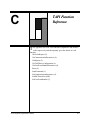
C. TAPI Function Reference . . . . . . . . . . . . . . . . . . . C-1
CheckForReports (3) . . . . . . . . . . . . . . . . . . . . . . . . . . C-3
GetCommunicationParameters (4) . . . . . . . . . . . . . . . C-4
GetReports (2) . . . . . . . . . . . . . . . . . . . . . . . . . . . . . . . C-6
GetTAPIDriverConfiguration (6) . . . . . . . . . . . . . . . . C-7
GetUserEventHandlerParameters (8) . . . . . . . . . . . . . C-8
Reset (0). . . . . . . . . . . . . . . . . . . . . . . . . . . . . . . . . . . . C-9
SendCommand (1) . . . . . . . . . . . . . . . . . . . . . . . . . . . C-10
SetCommunicationParameters (5) . . . . . . . . . . . . . . . C-11
SetSBCFrameSize (40H) . . . . . . . . . . . . . . . . . . . . . . C-13
SetUserEventHandler (7). . . . . . . . . . . . . . . . . . . . . . C-14
D. CTKERN Function Reference . . . . . . . . . . . . . . . D-1
GetCalibrationTableEntry (7) . . . . . . . . . . . . . . . . . . . D-5
GetCommunicationParameters (22) . . . . . . . . . . . . . . D-7
GetCTKERNDriverConfiguration (20) . . . . . . . . . . . . D-8
GetCurrentCalibrationModeAndParameters (5) . . . . . D-9
GetCurrentScalingModeAndParameters (10) . . . . . . D-10
GetTAPIDriverConfiguration (19) . . . . . . . . . . . . . . D-11
GetTemporalFilterModeAndParameters (16) . . . . . . D-12
GetTouchState (1) . . . . . . . . . . . . . . . . . . . . . . . . . . . D-13
GetTouchSystemStatus/Configuration (17) . . . . . . . D-15
GetUserEventHandlerModeAndParameters (25) . . . D-16
GetZ-AxisScalingModeAndParameters (13) . . . . . . D-17
Reset (0). . . . . . . . . . . . . . . . . . . . . . . . . . . . . . . . . . . D-18
SendSmart-FrameProtocolCommand
AndGetReport (18) . . . . . . . . . . . . . . . . . . . . . . . . D-20
SetCalibrationMode (3) . . . . . . . . . . . . . . . . . . . . . . . D-22
SetCalibrationParameters (4). . . . . . . . . . . . . . . . . . . D-23
SetCalibrationTableEntry (6) . . . . . . . . . . . . . . . . . . D-24
SetCommunicationParameters (21) . . . . . . . . . . . . . . D-26
SetScalingMode (8) . . . . . . . . . . . . . . . . . . . . . . . . . . D-28
v
Table of Contents
CARROLL TOUCH
SetScalingParameters (9). . . . . . . . . . . . . . . . . . . . . . D-29
SetTemporalFilterMode (14) . . . . . . . . . . . . . . . . . . . D-31
SetTemporalFilterParameters (15) . . . . . . . . . . . . . . D-34
SetTouchState (2) . . . . . . . . . . . . . . . . . . . . . . . . . . . D-36
SetUserEventHandlerMode (23) . . . . . . . . . . . . . . . . D-37
SetUserEventHandlerParameters (24) . . . . . . . . . . . . D-39
SetZ-AxisScalingMode (11) . . . . . . . . . . . . . . . . . . . D-40
SetZ-AxisScalingParameters (12) . . . . . . . . . . . . . . . D-41
E. Dynamic Link Library (DLL) Function Reference E-1
DisableMouse (11) . . . . . . . . . . . . . . . . . . . . . . . . . . . E-3
DisableTouch (12) . . . . . . . . . . . . . . . . . . . . . . . . . . . . E-4
EnableMouse (9) . . . . . . . . . . . . . . . . . . . . . . . . . . . . . E-5
EnableTouch (10) . . . . . . . . . . . . . . . . . . . . . . . . . . . . E-6
GetMouseInfo (13) . . . . . . . . . . . . . . . . . . . . . . . . . . . E-7
GetTemporalFilterInfo (18) . . . . . . . . . . . . . . . . . . . . . E-8
GetTouchInfo (14) . . . . . . . . . . . . . . . . . . . . . . . . . . . . E-9
GetTouchStateandCoord (5) . . . . . . . . . . . . . . . . . . . E-10
InitializeTouch (16) . . . . . . . . . . . . . . . . . . . . . . . . . . E-11
SetCalibInfo (7) . . . . . . . . . . . . . . . . . . . . . . . . . . . . . E-12
SetTemporalFilterInfo (17) . . . . . . . . . . . . . . . . . . . . E-14
SetTouchEvents (8) . . . . . . . . . . . . . . . . . . . . . . . . . . E-16
Glossary . . . . . . . . . . . . . . . . . . . . . . . . . . . . . . . . . . .GL-1
Index . . . . . . . . . . . . . . . . . . . . . . . . . . . . . . . . . . . . . . IN-1
vi
CARROLL TOUCH
Table of Contents
List of Figures
Figure 1-1. Infrared Touch Frame . . . . . . . . . . . . . . . . . . . . . . . . 1-2
Figure 1-2. Beam Averaging - Example 1 . . . . . . . . . . . . . . . . . . 1-3
Figure 1-3. Beam Averaging - Example 2 . . . . . . . . . . . . . . . . . . 1-4
Figure 2-1. Guided Wave Touch Screen . . . . . . . . . . . . . . . . . . . 2-2
Figure 3-1. Built-In Smart-Frame Controller Hardware . . . . . . .
Figure 3-2. RS-232 Controller Hardware (Modular IR Touch
Systems) . . . . . . . . . . . . . . . . . . . . . . . . . . . . . . . . . . . . . . . . . .
Figure 3-3. SBC and HBC Hardware (Modular IR Touch
Systems) . . . . . . . . . . . . . . . . . . . . . . . . . . . . . . . . . . . . . . . . . .
Figure 3-4. Touch Control Software . . . . . . . . . . . . . . . . . . . . . . .
Figure 3-5. Touch Calibration Screen . . . . . . . . . . . . . . . . . . . . .
3-2
3-3
3-4
3-5
3-6
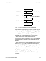
Figure 7-1. Touch System to Application Communication . . . . . 7-3
Figure 7-2. Calibration Mode Fixed or Automatic and Scaling
Mode Fixed or Automatic . . . . . . . . . . . . . . . . . . . . . . . . . . . . 7-6
Figure 7-3. Calibration Mode Fixed or Automatic and Scaling
Mode Disabled . . . . . . . . . . . . . . . . . . . . . . . . . . . . . . . . . . . . . 7-7
Figure 7-4. Calibration Mode Disabled and Scaling Mode
Fixed or Automatic . . . . . . . . . . . . . . . . . . . . . . . . . . . . . . . . . 7-7
Figure 7-5. Calibration Mode Disabled and Scaling Mode
Disabled . . . . . . . . . . . . . . . . . . . . . . . . . . . . . . . . . . . . . . . . . . 7-8
Figure 7-6. Calibration Main Menu Screen . . . . . . . . . . . . . . . . 7-15
Figure 7-7. Calibration Menu Screen . . . . . . . . . . . . . . . . . . . . . 7-16
Figure 7-8. Calibration Target Screen . . . . . . . . . . . . . . . . . . . . 7-16
Figure 7-9. Calibration Other Video Mode Screen #1 . . . . . . . . 7-17
Figure 7-10. Calibration Other Video Mode Screen #2 . . . . . . . 7-17
Figure 7-11. Calibration Other Video Mode Screen #3 . . . . . . . 7-18
Figure 7-12. Calibration Manual Edit Menu Screen . . . . . . . . . 7-19
Figure 7-13. Calibration Exit Prompt Screen . . . . . . . . . . . . . . . 7-19
Figure B-1. Flow Diagram for Report Transfer Mode . . . . . . . . B-19
Figure D-1. Temporal Filter Spatial Box Size . . . . . . . . . . . . . . D-32
vii
Table of Contents
viii
CARROLL TOUCH
CARROLL TOUCH
Table of Contents
List of Tables
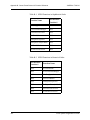
Table 1-1. Failed Beam Timing Parameters . . . . . . . . . . . . . . . . . 1-5
Table 3-1. HBC I/O Registers . . . . . . . . . . . . . . . . . . . . . . . . . . . 3-9
Table 3-2. Status Register Bit 0 Values . . . . . . . . . . . . . . . . . . . 3-10
Table 3-3. Status Register Bit 1 Values . . . . . . . . . . . . . . . . . . . 3-10
Table 4-1. SFP Communication Commands . . . . . . . . . . . . . . . .
Table 4-2. SFP Reporting Method Commands . . . . . . . . . . . . . .
Table 4-3. SFP Touch Mode Commands . . . . . . . . . . . . . . . . . . .
Table 4-4. SFP Information Request Commands . . . . . . . . . . . . .
Table 4-5. SFP System Commands . . . . . . . . . . . . . . . . . . . . . . .
Table 4-6. SFP Default Settings . . . . . . . . . . . . . . . . . . . . . . . . . .
4-3
4-4
4-4
4-5
4-6
4-9
Table 6-1. TAPI Error Messages and Explanations . . . . . . . . . . . 6-6
Table 7-1. CTKERN Error Messages . . . . . . . . . . . . . . . . . . . . . 7-10
Table A-1. SFP Commands in Alphabetical Order . . . . . . . . . . . A-3
Table A-2. SFP Commands in Numerical Order . . . . . . . . . . . . . A-4
Table A-3. Smart-Frame Protocol Error Report Error Codes . . . A-16
Table A-4. Touch System Default Settings . . . . . . . . . . . . . . . . A-34
Table B-1. SFP-II Functions in Alphabetical Order . . . . . . . . . . . B-2
Table B-2. SFP-II Functions in Numerical Order . . . . . . . . . . . . B-2
Table B-3. ComponentTypes, AttributeTags and
AttributeValues . . . . . . . . . . . . . . . . . . . . . . . . . . . . . . . . . . . . B-5
Table C-1. TAPI Functions in Alphabetical Order . . . . . . . . . . . . C-2
Table C-2. TAPI Functions in Numerical Order . . . . . . . . . . . . . C-2
Table C-3. Typical BL/BH Register Contents . . . . . . . . . . . . . . . C-7
Table D-1. CTKERN Functions in Alphabetical Order . . . . . . . . D-3
Table D-2. CTKERN Functions in Numerical Order . . . . . . . . . . D-4
Table D-3. Typical BX Register Contents . . . . . . . . . . . . . . . . . . D-8
Table D-4. Typical BL/BH Register Contents . . . . . . . . . . . . . . D-11
Table E-1. Windows Driver DLL Functions in
Alphabetical Order . . . . . . . . . . . . . . . . . . . . . . . . . . . . . . . . . . E-2
Table E-2. Windows Driver DLL Functions in
Numerical Order . . . . . . . . . . . . . . . . . . . . . . . . . . . . . . . . . . . E-2
Table E-3. Definition of Touch Events . . . . . . . . . . . . . . . . . . . E-17
ix
Table of Contents
x
CARROLL TOUCH
Welcome
s computers become a part of daily life, a technology that makes
them easier to use has become a necessity. Carroll Touch provides
the solution through the power of touch.
A
Thank you for your purchase of a Carroll Touch product and welcome
to Carroll Touch.
Purpose
This Programmer’s Guide is designed to:
•
Give an overview of the touch technologies used by Carroll Touch,
with a particular emphasis on hardware and software information
(such as calibration and initialization) needed by programmers.
•
Define the use and functions of the Smart-Frame Protocol, the
Smart-Frame Protocol II, the Touch Application Program Interface
(TAPI) driver, the CTKERN application interface, and the
Windows driver dynamic link libraries (DLLs).
Audience
This guide is designed for the programmer or software engineer who
integrates Carroll Touch touch systems with host computer systems.
Organization
Chapter 1, “Introduction to Infrared Touch Systems,” is an overview of
Carroll Touch infrared touch system hardware and operating principles.
Touch System Programmer’s Guide
xi
Welcome
CARROLL TOUCH
Chapter 2, “Introduction to Guided Wave Touch Systems,” is an
overview of Carroll Touch guided wave touch system hardware and
operating principles.
Chapter 3, “General Programming Issues,” includes information on
programming topics that apply to all Carroll Touch touch systems, such
as calibration and HBC I/O registers.
Chapter 4, “Smart-Frame Protocol,” gives an overview of the SFP
firmware protocol, including a discussion of command and report
types, initialization, timing, and programming tips and examples.
Chapter 5, “Smart-Frame Protocol II,” gives an overview of the SFP-II
firmware protocol, which extends the capabilities of SFP by offering
support of z-axes and higher resolution. Explanations of command and
report formats are included.
Chapter 6, “Touch Application Program Interface (TAPI),” includes an
overview of the TAPI software functions, and TAPI driver installation
and initialization information.
Chapter 7, “CTKERN,” includes an overview of the CTKERN
software functions, CTKERN driver installation, and parameters. It
also discusses the operation of the CTKERN calibration program
(CALIB.EXE).
Chapter 8, “Dynamic Link Library (DLL) Functions,” describes how to
use the DLL function calls to the Carroll Touch Windows driver.
Appendix A, “Smart-Frame Protocol Command Reference,” gives the
specifications for each SFP command and report.
Appendix B, “Smart-Frame Protocol II Function Reference,” gives the
specifications for each SFP-II function.
Appendix C, “TAPI Function Reference,” gives the specifications for
each TAPI function.
Appendix D, “CTKERN Function Reference,” gives the specifications
for each CTKERN function.
Appendix E, “Dynamic Link Library (DLL) Function Reference,”
gives the specifications for each Windows driver DLL.
xii
Touch System Programmer’s Guide
CARROLL TOUCH
Welcome
Conventions
For clarity, this guide uses certain conventions to visually distinguish
different types of information. The conventions are:
•
Bold is used to emphasize a word or phrase, including definitions
of important concepts.
•
SMALL CAPITAL LETTERS (such as SPACE or ENTER) indicates a
key on the keyboard.
•
Courier font indicates file names, directory names, messages
displayed by the computer, parameters in command lines, and
information to be typed by the user.
•
Italics indicate a command, function name, or mode (such as
Debug Mode).
•
Reports (such as the Touch Coordinate Report) and menus (such as
the Configuration Menu) use initial capital letters.
•
Courier italic font indicates a variable in a command line
for which you must substitute a value.
•
Hexadecimal numbers in text are identified with capital H; for
example, 1BH is the hexadecimal value 1B. Command and report
formats and examples reproduce numbers as they appear on the
screen and thus do not use the H convention.
•
Information of particular importance or actions that may have
undesirable results if performed improperly are included under the
headings Note and Caution.
Touch System Programmer’s Guide
xiii
Welcome
xiv
CARROLL TOUCH
Touch System Programmer’s Guide
1
Introduction to
Infrared Touch
Systems
T
his chapter gives an overview of Carroll Touch scanning infrared
touch systems, and covers the following topics:
• Overview.
• Touch Frames.
• Touch Controllers.
• Interpolating Touch Coordinates.
• Reporting Touch Coordinates.
• Failed Beams.
Touch System Programmer’s Guide
1-1
Chapter 1 - Introduction to Infrared Touch Systems
CARROLL TOUCH
Overview
A Carroll Touch infrared touch system consists of a touch controller and
touch frame or a combined touch frame and controller. The touch
system uses scanning infrared (IR) beam technology to detect operator
input. Generating an invisible grid of IR light beams in front of the host
video display screen, the touch system reports touch input when the IR
light field is interrupted by a stylus (typically a finger). This input can
be used by a touch application just as similar applications use input from
pointing devices such as a mouse, light pen or trackball.
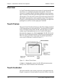
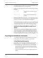
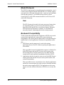
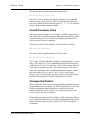
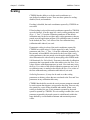
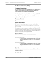
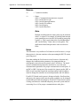
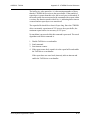
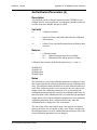
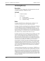
Touch Frames
The typical Carroll Touch touch frame is a thin, flat rectangle comprised
of four joined printed circuit boards (PCBs). Two adjacent PCBs contain
arrays of IR light emitting diodes (LEDs), while the other two PCBs
contain arrays of phototransistor/receivers. Each IR LED and the
phototransistor opposite it is called an opto-pair. The IR LED of each
opto-pair emits an IR light beam that is detected by the phototransistor.
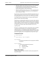
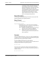
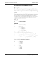
The x-axis and y-axis arrays of opto-pairs are pulsed sequentially to
create a grid of IR beams, as shown in Figure 1-1.
Figure 1-1. Infrared Touch Frame
A beam, or a beam pair, consists of an IR LED and phototransistor
directly across from each other in the touch frame.
Touch Controller
The touch controller is the circuitry required to create and monitor the
IR grid. A sequence of electrical pulses is sent to the LEDs to create the
1-2
Touch System Programmer’s Guide
CARROLL TOUCH
Chapter 1 - Introduction to Infrared Touch Systems
grid of IR beams in front of the video display surface. This grid of IR
beams is the touch active area.
When a stylus enters the touch active area, light beams are obstructed at
a particular location on the grid. The touch frame then transmits to the
controller a list that indicates which beams have been interrupted. The
controller converts this list into an x, y coordinate that identifies the
location of the touch. The x, y coordinate data is transmitted to the host
processor via the PC bus or the RS-232 serial port and is then processed
and used by the application program.
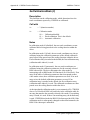
Interpolating Touch Coordinates
To achieve finer resolution than the physical IR beam grid provides,
Carroll Touch IR touch systems interpolate a virtual beam between each
pair of physical beams. The physical beams are assigned even numbers
(0, 2, 4, and so on). The virtual beams are assigned odd numbers (1, 3,
5, and so on). The combination of physical beams and virtual beams
results in a set of logical beams.
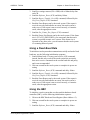
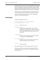
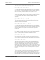
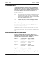
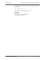
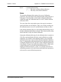
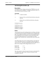
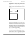
The coordinate system formed by the logical beams is called the logical
coordinate system. The origin of the logical coordinate system (0, 0) is
located in the upper left corner of the display. When multiple beams are
interrupted, the touch system averages them and reports one x, y logical
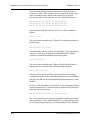
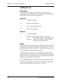
coordinate pair to the host, a process known as beam averaging.
Examples of beam averaging are shown in Figures 1-2 and 1-3.
00
02
04
06
08
10
00
02
4,4
04
06
08
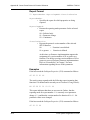
Figure 1-2. Beam Averaging - Example 1
In Figure 1-2, beams 2, 4, and 6 are interrupted on both the x- and
y-axes. The logical coordinate pair reported to the host is 4, 4.
Touch System Programmer’s Guide
1-3
Chapter 1 - Introduction to Infrared Touch Systems
00
02
04
06
CARROLL TOUCH
08
10
00
02
04
5,5
06
08
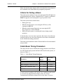
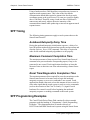
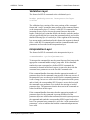
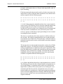
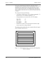
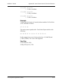
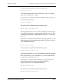
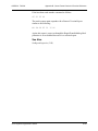
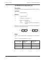
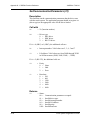
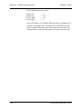
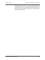
Figure 1-3. Beam Averaging - Example 2
In Figure 1-3, beams 2, 4, 6, and 8 are interrupted on both the x- and
y-axes. The logical coordinate pair reported to the host is 5, 5.
Reporting Touch Coordinates
For a touch to be reported, at least one x beam and one y beam must be
interrupted. If no beams are interrupted in either the x- or y-axis, the
touch is ignored.
The lowest logical coordinate reported for any axis on any touch frame
is zero. The maximum logical coordinate that may be reported for a
given touch frame axis may be determined from the number of physical
beams on that touch frame axis as follows:
Maximum logical coordinate = 2 x (number of physical beams - 1)
For example, on a frame that has 40 x-axis beams and 30 y-axis beams,
the maximum logical coordinates for the frame are:
Maximum logical x coordinate = 2 x (40 - 1) = 78
Maximum logical y coordinate = 2 x (30 - 1) = 58
Therefore, the reported coordinates would range from 0 to 78 on the
x-axis and from 0 - 58 on the y-axis.
Failed Beams
Carroll Touch touch systems have incorporated into their firmware a
mechanism for detecting defective beam pairs and removing them from
consideration when determining the location of a stylus within the touch
frame. This failed beam mechanism provides a measure of fault
tolerance for the touch system so that, in the event of an opto-component
1-4
Touch System Programmer’s Guide
CARROLL TOUCH
Chapter 1 - Introduction to Infrared Touch Systems
failure, the touch system simply suffers a localized loss of resolution in
one coordinate axis, rather than being completely inoperable.
Criteria for Failing a Beam
The touch system considers a beam to be interrupted if the IR light level
at the phototransistor is below a threshold level. A beam is considered
failed if it appears to be interrupted for a given period of time.
The touch system detects failed beams:
•
During power up.
•
When the touch system is reset using the SFP Reset (45H)
command or BREAK.
•
When the touch system diagnostics are run using the SFP
Run_Diagnostics (3AH) command.
•
While the touch system is scanning the beams during normal
operation.
In the first three cases, the time required to fail a beam is less than one
second. In the last case, the time required to fail a beam is determined
by the failed beam timing parameters.
The touch system maintains a table of beams that have been determined
to have failed.
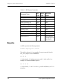
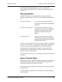
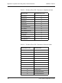
Failed Beam Timing Parameters
The values for the various failed beam timing parameters are different
for ASIC-based touch systems and non-ASIC-based touch systems, as
shown in Table 1-1.
Table 1-1. Failed Beam Timing Parameters
Parameter
ASICBased
Non-ASICBased
Valid Touch Fail Time
59 - 62 sec.
225 - 270 sec.
Non-Contiguous Touch Fail Time
2.2 - 4.4 sec.
10 - 20 sec.
Single Axis Touch Fail Time
2.2 - 4.4 sec.
10 - 20 sec.
Unfail Time
2.2 - 4.4 sec.
10 - 20 sec.
A touch system is probably ASIC-based if it is a modular touch system,
or an invasively integrated Smart-Frame with a five switch
Communication Parameters jumper block on the frame. If you are
Touch System Programmer’s Guide
1-5
Chapter 1 - Introduction to Infrared Touch Systems
CARROLL TOUCH
unsure whether your system is ASIC-based and if you need to know the
values of the failed beam timing parameters, use the touch system
diagnostics software (CTDIAG) to observe the amount of time required
to fail beams that are interrupted by a valid touch.
Table 1-1 gives a range of values rather than a specific value because the
touch system firmware checks for failed beams at a regular interval (2.2
seconds or 10 seconds). A beam that appears to be interrupted just after
the firmware checks takes longer to fail than a beam that appears to be
interrupted just before the firmware checks.
Note
Custom touch systems may have different values for the failed
beam timing parameters from those given in Table 1-1.
During normal operation, with the touch system scanning the beams, a
beam is considered failed if it is interrupted for the amount of time
specified by the Valid Touch Fail Time parameter and if the pattern of
interrupted beams appears to indicate a valid touch with a single stylus.
(A touch is considered valid if there appears to be one and only one
region of contiguous interrupted beams in each coordinate axis.) Thus,
a single stylus that remains stationary within the touch screen for the
Valid Touch Fail Time causes beams to be failed.
If beams are interrupted on only one axis of the touch frame, the
interrupted beams are failed in the amount of time specified by the
Single Axis Touch Fail Time parameter.
For any other pattern of interrupted beams, such as more than one region
of interrupted beams in an axis, the interrupted beams are failed in the
amount of time specified by the Non-Contiguous Touch Fail Time
parameter. Thus, multiple styli that remain stationary for longer than the
Non-Contiguous Touch Fail Time result in beams being failed, as do
non-contiguous touches.
For example, if you place a piece of tape over the opto-devices in one
axis of the touch screen, the beams obstructed by the tape are determined
by the touch system firmware to be failed and are added to the failed
beam table only after the amount of time specified by the Invalid Touch
Fail Time parameter has elapsed. If you then remove the tape, the time
specified in the Unfail Time parameter must elapse before the beams are
considered unfailed by the touch system firmware.
1-6
Touch System Programmer’s Guide
CARROLL TOUCH
Chapter 1 - Introduction to Infrared Touch Systems
Criteria for Unfailing a Beam
If a failed beam appears not to be interrupted for the amount of time
specified by the Unfail Time parameter, it is unfailed and removed from
the failed beam table by the touch system firmware.
Failed Beam Reports
Two SFP commands can be used to generate reports related to the failed
beam status of the touch system: Get_Error_Report (32H) and
Get_Failed_Beam_Report (36H). See Appendix A, “Smart-Frame
Protocol Command Reference,” for details on these commands.
Touch System Programmer’s Guide
1-7
Chapter 1 - Introduction to Infrared Touch Systems
1-8
CARROLL TOUCH
Touch System Programmer’s Guide
2
Introduction to
Guided Wave
Touch Systems
T
his chapter gives an overview of Carroll Touch guided wave touch
systems and covers the following topics:
• Overview.
• Touch Screens.
• Touch Controllers.
• EEPROM File and Parameters.
Touch System Programmer’s Guide
2-1
Chapter 2 - Introduction to Guided Wave Touch Systems
CARROLL TOUCH
Overview
A Carroll Touch guided wave touch system consists of a touch
controller and touch screen. The touch system uses guided acoustic
wave (GW) technology to detect operator input for a variety of
applications. Generating invisible acoustic waves, the touch system
reports touch input when the wave motion is attenuated by a stylus
(typically a finger). This input can be used by a touch application just as
similar applications use input from pointing devices such as a mouse,
light pen or trackball.
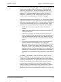
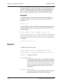
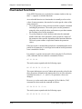
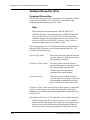
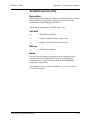
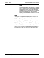
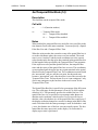
Touch Screens
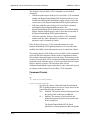
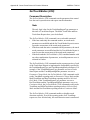
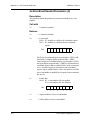
Guided acoustic wave technology is based on transmitting acoustic
waves through a glass overlay placed over the display surface. A
transducer mounted on the edge of the glass emits an acoustic wave. The
wave travels along the reflector array, is redirected across the overlay to
the reflecting edge, and returns to the array where it is reflected back to
the transducer. The first reflector will send a signal back first, then the
second, and so on, as shown in Figure 2-1.
Figure 2-1. Guided Wave Touch Screen
Touch Controllers
The touch controller is the circuitry required to create and monitor the
acoustic waves. A sequence of electrical pulses is sent to the transducer
located in the upper left of the glass overlay to generate the acoustic
waves. The area covered by the acoustic waves is the touch active area.
2-2
Touch System Programmer’s Guide
CARROLL TOUCH
Chapter 2 - Introduction to Guided Wave Touch Systems
When a stylus enters the touch active area, acoustic waves are attenuated
at that location on the overlay. The touch screen then transmits to the
controller information indicating the location of the attenuated waves.
The controller converts this information to an x, y coordinate that
identifies the location of the touch. The x, y coordinate data is
transmitted to the host processor via the controller and is then processed
and used by the application program.
EEPROM File and Parameters
Guided wave touch screens use an electrically erasable programmable
read-only memory (EEPROM) chip. An associated file stores the values
of the EEPROM parameters that control many features of the touch
screen. The following EEPROM values may be displayed, modified,
saved, and restored:
•
Touch sensitivity.
•
Touch active region.
•
Transducer corner.
•
Coordinate origin corner.
•
Transducer orientation.
•
Touch refresh time.
•
No touch refresh time.
•
Temporal filter space.
•
Temporal filter time.
Touch System Programmer’s Guide
2-3
Chapter 2 - Introduction to Guided Wave Touch Systems
2-4
CARROLL TOUCH
Touch System Programmer’s Guide
3
General
Programming
Issues
T
his chapter includes information that may apply to any Carroll
Touch touch system. It discusses the following topics:
• Hardware Configurations.
• Calibration.
• HBC I/O Registers.
Touch System Programmer’s Guide
3-1
Chapter 3 - General Programming Issues
CARROLL TOUCH
Hardware Configurations
There are two major types of Carroll Touch controller configurations:
built-in controllers (used in infrared Smart-Frames) and external
controllers (used in modular infrared and guided wave touch systems).
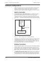
Built-In Controllers
An infrared Smart-Frame touch system has controller electronics
built onto the touch frame itself. The Smart-Frame touch system
communicates directly with the host computer through the host serial
port. Figure 3-1 illustrates the built-in Smart-Frame controller hardware.
Built-in
Controller
(Infrared
SmartFrame)
RS-232 Cable
Host PC
Figure 3-1. Built-In Smart-Frame Controller Hardware
The Smart-Frame communicates serially with the host computer using a
selectable baud rate (300, 600, 1200, 2400, 4800, 9600, 19,200 or
autobaud) and parity (odd, even, none, autoparity). Default values for
the standard Smart-Frame are autobaud and autoparity.
External Controllers
External controllers connect to the touch system via the Modular Digital
Interface (MDI) cable in modular infrared touch systems or an 8-pin
mini-DIN sensor cable in guided wave systems. The MDI cable carries
digital signals, while the mini-DIN sensor cable carries analog signals.
A modular infrared touch system consists of any one of a number of
IR-transparent protective bezels that house and protect a touch frame,
matched with any one of three modular touch controllers: the software-
3-2
Touch System Programmer’s Guide
CARROLL TOUCH
Chapter 3 - General Programming Issues
based controller (SBC), hardware-based controller (HBC), and RS-232
controller. A guided wave touch system uses HBCs or RS-232
controllers. Figure 3-2 illustrates the RS-232 controller hardware.
External
Controller
(Guided Wave
or Modular IR
Touch Frame)
MDI/Sensor Cable
RS-232
Controller
RS-232 Cable
Host PC
Figure 3-2. RS-232 Controller Hardware (Modular IR Touch Systems)
The RS-232 controller is a PCB that has its own protective housing and
requires an external power supply. The RS-232 controller
communicates with the modular touch frame via the MDI cable and with
the host computer through the host serial port.
The RS-232 controller communicates serially with the host computer
using a selectable baud rate (300, 600, 1200, 2400, 4800, 9600, 19,200
or autobaud) and parity (odd, even, none, autoparity). Default values for
the RS-232 controller are autobaud and autoparity.
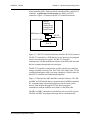
Figure 3-3 illustrates the SBC and HBC controller hardware. The SBC
and HBC are PCBs that fit into an expansion slot of an IBM-compatible
PC, communicating with and drawing power for the touch system
directly from the host through the PC bus. Both controllers
communicate with the modular touch frame via the MDI cable.
The SBC and HBC communicate with the host via several I/O registers.
The SBC and HBC also support interrupt-driven communications.
Touch System Programmer’s Guide
3-3
Chapter 3 - General Programming Issues
CARROLL TOUCH
Modular
IR Touch
Frame
Modular
IR Touch
Frame
MDI Cable
SBC
Controller
Card
SBC(TAPI)
Driver
Host
PC
SBC TAPI Driver
Software Interrupt
HBC
Controller
Card
Host
PC
PC Bus I/O Ports
Figure 3-3. SBC and HBC Hardware (Modular IR Touch Systems)
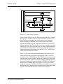
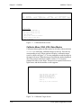
Application Program Interface
As shown in Figure 3-4, application programs may interface with
Smart-Frame systems and systems using the HBC or RS-232 controller
directly via the Smart-Frame Protocol. Smart-Frame systems and
systems using the RS-232 controller are identical in terms of software.
Both communicate using the Smart-Frame Protocol via the RS-232
serial interface. Systems using the HBC communicate with the
application program using the Smart-Frame Protocol via the HBC I/O
registers. For more details about the I/O registers, see “HBC I/O
Registers” later in this chapter. The SBC cannot use the Smart-Frame
Protocol directly because the SBC has no processor on board. The
Smart-Frame Protocol is discussed in Chapter 4, “Smart-Frame
Protocol.”
As also shown in Figure 3-4, application programs may interface with
Smart-Frame systems and systems using the SBC, HBC, or RS-232
controller using the Smart-Frame Protocol via a Touch Application
Program Interface (TAPI) driver. This is the same Smart-Frame
Protocol used when interfacing directly to the touch system hardware.
3-4
Touch System Programmer’s Guide
CARROLL TOUCH
Chapter 3 - General Programming Issues
A
P
P
L
I
C
A
T
I
O
N
P
R
O
G
R
A
M
CTKERN
CTKERN
SMART-FRAME
PROTOCOL (VIA TAPI)
TAPI
RS-232
DRIVER
TAPI
HBC
DRIVER
RS-232
CONTROLLER
HBC
CONTROLLER
SMART-FRAME
PROTOCOL (DIRECT)
SMARTFRAME
TAPI
SBC
DRIVER
SBC
CONTROLLER
MDI
FRAME
Figure 3-4. Touch Control Software
There are three TAPI drivers: the SBC driver, the HBC driver, and the
RS-232 driver. The RS-232 driver works with Smart-Frames as well.
Each TAPI driver communicates with the touch system using the
hardware interface appropriate for the touch system, and with the
application program using the TAPI functions that are accessed via a
software interrupt. The TAPI interface is the same regardless of which
TAPI driver is used. This means that you may make an application touch
system hardware-independent by interfacing at the TAPI driver level
rather than directly to the touch system hardware. The TAPI software
functions are discussed in Chapter 6.
Figure 3-4 also shows that application programs may interface with
Smart-Frame systems and systems using the SBC, HBC, or RS-232
controller via the CTKERN driver. The CTKERN driver communicates
with the touch system using the TAPI driver appropriate for the touch
system, and with the application program using the CTKERN functions,
which are accessed via a software interrupt. CTKERN is a DOS driver
that provides calibration and scaling support, as well as easy-to-use
touch state reporting. CTKERN also features an installable user event
handler that allows interrupt-driven communication with the application
program. The CTKERN functions are discussed in Chapter 7.
Touch System Programmer’s Guide
3-5
Chapter 3 - General Programming Issues
CARROLL TOUCH
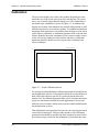
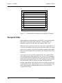
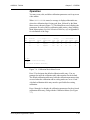
Calibration
The size of the display area of the video monitor frequently does not
match the size of the touch active area of the touch frame. The touch
active area is usually larger than the display area. The relationship of
touch and video coordinates is shown in Figure 3-5. In addition, the
display area on most video monitors may actually shift position or drift,
while the touch active area remains constant. To establish and maintain
alignment of the touch active area with the active display area, the touch
screen must be calibrated. A calibration procedure such as the one that
follows identifies the touch coordinates of the extreme outside corners
of the video image displayed on the monitor and derives calibration
parameters that may then be used to convert touch coordinates into
video coordinates.
TOUCH_MAX_X
0
0
0
VIDEO_MAX_X
0
VIDEO_MAX_Y
TOUCH_MAX_Y
Figure 3-5. Touch Calibration Screen
It is strongly recommended that a calibration program be included in any
touch application or driver. Touch applications or drivers should not use
hard-wired values that are specific to a particular touch frame and
monitor. Use of a calibration program takes care of variations in monitor
image size and location and allows touch applications to be used on
different sizes of monitors and/or touch systems without modifying the
touch application or driver.
This calibration must be performed at least once for each physical touch
screen/video monitor pair. This procedure produces four calibration
parameters that should be stored by the host computer in some form of
nonvolatile storage, which lets the calibration be performed only once.
3-6
Touch System Programmer’s Guide
CARROLL TOUCH
Chapter 3 - General Programming Issues
Once calibration is completed, the host software may use the calibration
parameters to convert touch coordinates into video coordinates (pixel
coordinates). These may then be used in the remainder of the host
software.
Some monitors do not maintain a constant video image size and
placement for all of the video modes that they support. For this reason,
the calibration should be performed using the same video mode as the
touch application in order to assure an accurate calibration.
Floating Point Calibration Program Design
When designing a program to calibrate the touch screen, include the
following steps:
1. Prompt the user to touch the upper left corner of the video screen.
2. Save the coordinates returned as TOUCH_UL_X and
TOUCH_UL_Y.
3. Prompt the user to touch the lower right corner of the video screen.
4. Save the coordinates returned as TOUCH_LR_X and
TOUCH_LR_Y.
A good way to prompt the user to touch the corners is to draw a
border around the edge of the screen and prompt the user to touch
each point using a target in the respective corner and text centered
on the screen.
5. Calculate the four calibration parameters as follows:
OFFSET_X = TOUCH_UL_X
OFFSET_Y = TOUCH_UL_Y
SCALE_X = VIDEO_MAX_X / (TOUCH_LR_X TOUCH_UL_X)
SCALE_Y = VIDEO_MAX_Y / (TOUCH_LR_Y TOUCH_UL_Y)
6. Save the four calibration parameters to a nonvolatile storage area, if
available. If none is available, the calibration procedure must be
followed each time the system is powered up.
The floating point calibration procedure is now complete. In your
application program, convert the touch coordinates reported by the
touch system into the equivalent video coordinates with these equations:
VIDEO_X = SCALE_X * (TOUCH_X - OFFSET_X)
VIDEO_Y = SCALE_Y * (TOUCH_Y - OFFSET_Y)
Touch System Programmer’s Guide
3-7
Chapter 3 - General Programming Issues
CARROLL TOUCH
You may also want to limit VIDEO_X and VIDEO_Y to the ranges
defined by VIDEO_MAX_X and VIDEO_MAX_Y. It is recommended
that the touch coordinates be converted to video coordinates
immediately upon their receipt from the touch system, and that video
coordinates be used in the remainder of the application program.
Floating Point Calibration Examples
If the coordinates resulting from calibration of a system with 640 x 480
resolution are:
TOUCH_UL_X
TOUCH_UL_Y
= 10
=7
TOUCH_LR_X
TOUCH_LR_Y
= 150
= 110
and the system has a resolution of 640 x 480:
VIDEO_MAX_X
VIDEO_MAX_Y
= 639
= 479
the four calculated calibration parameters are:
OFFSET_X
OFFSET_Y
= 10
=7
SCALE_X
SCALE_Y
= 639 / (150 - 10) = 4.5643
= 479 / (110 - 7) = 4.65
Following are three examples of how to solve for different values of
VIDEO_X and VIDEO_Y:
If TOUCH_X = 7 and TOUCH_Y = 10, then:
VIDEO_X = 4.5643 * (10 - 10) = 0
VIDEO_Y = 4.65 * (7 - 7)
=0
If TOUCH_X = 60, and TOUCH_Y= 80, then:
VIDEO_X = 4.5643 * (60 - 10) = 228
VIDEO_Y = 4.65 * (80 - 7)
= 339
If TOUCH_X = 150, and TOUCH_Y= 110, then:
VIDEO_X = 4.5643 * (150 - 10) = 639
VIDEO_Y = 4.65 * (110 - 7)
= 479
3-8
Touch System Programmer’s Guide
CARROLL TOUCH
Chapter 3 - General Programming Issues
HBC I/O Registers
Overview
The HBC communicates with the PC through the PC bus via three
consecutive I/O registers. The base address of these I/O registers is set
by the I/O address jumpers on the HBC board, and may be set in
increments of 16 to any I/O address between 200H and 3F0H inclusive.
The three I/O registers are defined in Table 3-1.
Table 3-1. HBC I/O Registers
I/O Address
Name
Read/
Write
Description
I/O Base
Address
Data Register
R/W
Used to send commands to
and receive reports from
the touch controller.
I/O Base
Address + 1
Status
Register
R
Used to check the touch
controller communications
status (i.e. ready to receive
commands, reports
available).
I/O Base
Address +2
Hardware
Reset Register
W
Used to reset the touch
controller.
The touch controller may be used in polling mode or in interrupt mode.
In polling mode, the application software must check the Status
Register before sending or receiving data. In interrupt mode, the
application software must check the Status Register when sending data
to the touch controller, but may install an interrupt handler to receive
data from the touch controller. The interrupt number used is set by the
interrupt number jumpers on the HBC board, as described in the HBC
installation instructions. When using polling mode, set these jumpers to
none to prevent the HBC from generating any interrupts.
Sending a Touch Command to the HBC
The procedure used to send a touch command to the HBC is the same
for both interrupt mode and polling mode.
Before sending a command to the touch controller, you must first
perform an I/O read of the Status Register (Base Address + 1). Bit 0 of
the Status Register indicates whether the touch controller is ready to
Touch System Programmer’s Guide
3-9
Chapter 3 - General Programming Issues
CARROLL TOUCH
receive a command or whether it is busy. Table 3-2 shows the values of
Bit 0 of the Status Register.
Table 3-2. Status Register Bit 0 Values
Bit 0
Description
0
Touch controller ready to receive command.
1
Touch controller busy.
If Bit 0 of the Status Register is 0, you may send a command to the touch
controller by performing an I/O write to the Data Register (Base
Address). If Bit 0 of the Status Register is 1, do not send a touch
command to the touch controller.
Receiving Touch Data from the HBC
The procedure used to receive data from the HBC differs depending on
which communication mode you are using.
Polling Mode
When using polling mode, the application software polls the Status
Register (Base Address + 1) to check if touch data is available in the
Data Register (Base Address).
Before reading the Data Register, you must first perform an I/O read of
the Status Register. Bit 1 of the Status Register indicates whether there
is touch data available in the Data Register. Table 3-3 shows the values
of Bit 1 of the Status Register.
Table 3-3. Status Register Bit 1 Values
Bit 1
Description
0
Touch data available.
1
No touch data available.
If Bit 1 of the Status Register is 0, you may receive a byte of touch data
by performing an I/O read of the Data Register. If Bit 1 of the Status
Register is 1, there is no data available in the Data Register.
3-10
Touch System Programmer’s Guide
CARROLL TOUCH
Chapter 3 - General Programming Issues
Interrupt Mode
When using interrupt mode, the touch controller uses a PC hardware
interrupt to notify the application software that touch data is available in
the Data Register (Base Address). When the display is touched with
touch enabled, or an information request command is received by the
touch system, the touch system sends touch data to the Data Register.
The HBC then interrupts the host computer, indicating that data is
available in the Data Register. The application software’s interrupt
handler should perform an I/O read of the Data Register to receive a byte
of touch data from the touch system.
Resetting the HBC
The procedure to perform a hardware reset on the HBC is the same for
both interrupt and polling communication modes. To cause a hardware
reset of the touch controller, perform an I/O write to the Hardware Reset
Register (Base Address + 2).
Note that the value of the data byte written to the Hardware Reset
Register does not matter.
Touch System Programmer’s Guide
3-11
Chapter 3 - General Programming Issues
3-12
CARROLL TOUCH
Touch System Programmer’s Guide
4
Smart-Frame
Protocol
his chapter gives an overview of the SFP firmware protocol,
including a discussion of command and report types, initialization,
timing, and programming tips and examples.
T
The chapter discusses the following topics:
•
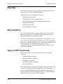
Overview.
•
SFP and SFP-II.
•
Types of SFP Commands.
•
Reports.
•
Touch System Initialization.
•
Touch System Initialization Examples.
•
Using an SBC.
•
Compatibility Issues/Programming Tips.
•
SFP Timing.
•
SFP Programming Examples.
See Appendix A, “Smart-Frame Protocol Command Reference,” for
the specifications of each Smart-Frame Protocol command.
Touch System Programmer’s Guide
4-1
Chapter 4 - Smart-Frame Protocol
CARROLL TOUCH
Overview
The Smart-Frame Protocol (SFP) regulates communication between
the touch system and the application program.
Smart-Frame Protocol commands are used to:
•
Initialize the touch system.
•
Establish host-to-touch communications.
•
Select the touch system reporting and operating modes.
•
Request special reports.
•
Manage report transfer.
•
Execute diagnostic functions.
SFP and SFP-II
The SFP, defined in 1985, is currently used by most Carroll Touch
touch systems, but will eventually be supplanted by Smart-Frame
Protocol II (SFP-II) on newer touch systems.
The SFP is implemented as a modal protocol, meaning that, even if a
touch system supports both the SFP and SFP-II, it can only support one
protocol at a time and, during that time, cannot accept commands from
the other protocol. To switch between protocols, use the
SwitchToSFP-II (65H) SFP command and the SwitchToClassicSFP
(64H) SFP-II function.
Types of SFP Commands
Smart-Frame Protocol commands are grouped into five logical
categories:
•
Communication commands.
•
Reporting method commands.
•
Touch mode commands.
•
Information request commands.
•
System commands.
SFP commands may be invoked with either a hexadecimal code or an
ASCII code, and many of the commands have associated reports. To
issue a command under the Smart-Frame Protocol, simply type its
function number. An SFP command example is 32, the hexadecimal
code for the Get_Error_Report (32H) command.
4-2
Touch System Programmer’s Guide
CARROLL TOUCH
Chapter 4 - Smart-Frame Protocol
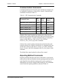
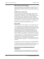
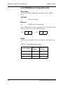
Communication Commands
Communication between the touch system and the host computer can
be regulated by hardware or software flow control. Communication
commands are shown in Table 4-1.
Table 4-1. SFP Communication Commands
Command Name
Hex
Code
ASCII
Code
Associated
Report
Hardware_Flow_Control_On
41H
A
None
Hardware_Flow_Control_Off
42H
B
None
Report_Transfer_Off
43H
C
None
Report_Transfer_On
44H
D
None
Get_One_Report
46H
F
varies
Hardware flow control regulates the transmission of data from the
touch system to the host and from the host to the touch system by using
RS-232 control signals. To enable and disable this type of data flow
control, use the Hardware_Flow_Control_On (41H) and
Hardware_Flow_Control_Off (42H) commands.
Software flow control regulates transmission of data from the touch
system to the host on a report-by-report basis. To implement this type
of data flow control, use the Report_Transfer_On (44H) command,
Report_Transfer_Off (43H) command, or the Get_One_Report (46H)
command.
The default flow control method is software flow control.
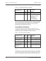
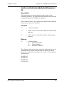
Reporting Method Commands
Reporting methods determine the form in which data is sent from the
touch system to the host. Both the desired reporting method and touch
mode should be selected before turning touch system scanning on,
although they may also be changed with scanning on. The commands
used to select the reporting method are shown in Table 4-2.
Touch System Programmer’s Guide
4-3
Chapter 4 - Smart-Frame Protocol
CARROLL TOUCH
Table 4-2. SFP Reporting Method Commands
Command Name
Hex
Code
ASCII
Code
Associated
Report
Scan_Reporting
22H
“
Scan Report
Coordinate_Reporting
23H
#
Touch Coordinate Report
Add Exit Coordinate
Point Report
Non-Contiguous
Coordinate Report
Scan reports present interrupt beam data with no software interpretation
and are used for diagnostic and testing purposes. Coordinate reports
present interrupt beam data in the form of x, y (x-axis, y-axis)
coordinate pairs for application processing.
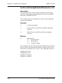
Touch Mode Commands
Touch mode commands select the conditions under which touch
coordinates are reported when the reporting method is set to coordinate
reporting. Touch mode commands are shown in Table 4-3.
Table 4-3. SFP Touch Mode Commands
Command Name
Hex
Code
ASCII
Code
Associated
Report
Enter_Point_Mode
25H
%
Touch Coordinate Report
Tracking_Mode
26H
&
Touch Coordinate Report
Continuous_Mode
27H
‘
Touch Coordinate Report
Exit_Point_Mode
28H
(
Touch Coordinate Report
Add_Exit_Point_
Modifier*
29H
)
Touch Coordinate Report
*Add Exit Point is a modifier that is used with other touch modes. It is not a stand-alone touch
mode.
To change the touch mode, simply send the touch mode command that
selects the new touch mode. For example, to change from Enter Point
Mode to Tracking Mode, send the Tracking_Mode (26H) command.
4-4
Touch System Programmer’s Guide
CARROLL TOUCH
Chapter 4 - Smart-Frame Protocol
Changing the touch mode clears the Add Exit Point modifier. To
disable the Add Exit Point modifier without changing the current touch
mode, simply send the desired touch mode command again.
For example, to select Tracking Mode with Add Exit Point, send the
Tracking_Mode (26H) command followed by the
Add_Exit_Point_Modifier (29H) command. To deselect Add Exit Point
and remain in Tracking Mode, send the Tracking_Mode (26H)
command again.
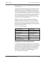
Information Request Commands
Information request commands query the touch system for system
status reports, such as error, configuration, firmware version, failed
beam, frame size, and state reports. Information request commands are
shown in Table 4-4.
Table 4-4. SFP Information Request Commands
Command Name
Hex
Code
ASCII
Code
Associated
Report
Get_Error_Report
32H
2
Error Report
Get_Configuration_Report
33H
3
Configuration Report
Get_Firmware_Version_
Report
34H
4
Firmware Version
Report
Get_Failed_Beam_Report
36H
6
Failed Beam Report
Get_Frame_Size_Report
37H
7
Frame Size Report
Get_State_Report
47H
G
State Report
System Commands
System commands control all touch system functions such as
initialization, software reset, diagnostics, and scanning. The system
commands are shown in Table 4-5.
Touch System Programmer’s Guide
4-5
Chapter 4 - Smart-Frame Protocol
CARROLL TOUCH
Table 4-5. SFP System Commands
Command Name
Hex
Code
ASCII
Code
Associated
Report
Echo_On
20H
Space
None
Echo_Off
21H
!
None
Touch_Scanning_On
2AH
*
None
Touch_Scanning_Off
2BH
+
None
Run_Diagnostics
3AH
:
Error Report
Software_Reset
3CH
<
None
Clear_Touch_Report_Buffer
3DH
=
None
Reset
45H
E
None
SwitchToSFP-II
65H
SFP-II Protocol
Version Report or
Error Report
Reports
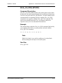
An SFP report has the following format:
header reportbytes trailer
The trailer is always FF. An example of a report returned from the
Get_Error_Report (32H) command is:
F8 00 FF
F8 is the header, 00 indicates no errors, and FF is the trailer. An
example of a touch coordinate report is:
FE 35 2D FF
FE is the header; 35 and 2D are the x, y touch coordinates; and FF is
the trailer.
4-6
Touch System Programmer’s Guide
CARROLL TOUCH
Chapter 4 - Smart-Frame Protocol
Touch System Initialization
To initialize a touch system that uses the Smart-Frame Protocol, take
the following steps:
1. Reset the touch system.
2. Perform the autobaud/autoparity sequence, if appropriate, then the
software reset command.
3. Check for any errors that may have been detected.
4. Set the desired reporting method and touch mode.
Details on each step are in the following sections.
Resetting the Touch System
The following methods may be used to reset the touch system. Be sure
to use a method that is appropriate for the touch system being used.
Power Cycle
This method resets everything. For touch systems that communicate
serially, Clear To Send (CTS) is deasserted (negative voltage) to
indicate that the touch system is busy until the touch system is ready to
accept commands. For serial touch systems that have their
communication parameters set to autobaud/autoparity, this occurs
when the touch system enters the autobaud sequence by sending breaks.
Dedicated Reset Signal
On some Smart-Frame systems, a dedicated reset signal line is present.
If present, this signal is on pin 8 of the 2 x 5 pin communication
connector that is on the frame. To reset the touch system, deassert this
pin by applying negative voltage for a minimum of 10 ms. This type of
reset is equivalent to cycling the power to the touch system. This signal
is not present on the modular RS-232 controller.
Break (Hardware Detected)
For touch systems that use the modular RS-232 controller, a break of at
least 400 ms resets the touch system. To send a break of 400 ms, set the
Transmit Data (TD) signal to the “space” condition (positive voltage),
wait 400 ms, and set the TD signal back to the “mark” condition
(negative voltage). For PC systems, the “Set Break” bit in the Line
Control Register of the 8250 USART chip is used to set and/or clear the
break condition. This type of reset is equivalent to cycling the power to
the touch system.
Touch System Programmer’s Guide
4-7
Chapter 4 - Smart-Frame Protocol
CARROLL TOUCH
HBC Hardware Reset Register
For touch systems that use the modular HBC, writing any value to the
HBC Hardware Reset Register (Base Address +2) resets the touch
system. This type of reset is equivalent to cycling the power to the touch
system.
Break (Firmware Detected)
For all touch systems that communicate serially, a break of at least
150ms resets the touch system. To send a break of 150ms, set the
Transmit Data (TD) signal to the “space” condition (positive voltage),
wait 150ms, and set the TD signal back to the “mark” condition
(negative voltage). For PC systems, the “Set Break” bit in the Line
Control Register of the 8250 USART chip is used to set and/or clear the
break condition. This type of reset is equivalent to cycling the power to
the touch system, except that Clear To Send (CTS) is not affected if
hardware flow control was not enabled before the reset.
Reset (45H)
This Smart-Frame Protocol command resets everything. If the touch
system communicates serially and hardware flow control is enabled,
CTS is deasserted (negative voltage) to indicate that the touch system
is busy until the touch system is ready to accept commands. For serial
touch systems that have their communication parameters set to
autobaud/autoparity, this occurs when the touch system enters the
autobaud/autoparity sequence by sending breaks. If hardware flow
control is disabled, Clear To Send (CTS) is not affected. This type of
reset is equivalent to cycling the power to the touch system, except that
the Clear To Send (CTS) is not affected if hardware flow control was
not enabled before the reset. Also, if the touch system communicates
serially but is set to use a fixed baud rate and parity (not
autobaud/autoparity), or if the touch system uses the HBC, the touch
system sends a Power Up Report (F1 FF) when it is ready to receive
commands.
In all cases, the touch system is ready to receive commands within one
second after the reset occurs. Touch applications must delay for one
second after resetting the touch system. In cases where a break is sent,
the one second time does not begin until the break is released.
Performing the Autobaud/Autoparity
Sequence
If you are using a touch system that communicates serially and is set to
use autobaud/autoparity, you must perform the autobaud/autoparity
4-8
Touch System Programmer’s Guide
CARROLL TOUCH
Chapter 4 - Smart-Frame Protocol
sequence to allow the touch system to establish baud rate and parity that
is used by the host.
To perform the autobaud/autoparity sequence, the host must send five
ASCII carriage returns (CR - 0DH) followed by a delay of at least
100ms after each carriage return. The touch system uses these carriage
returns to determine the baud rate used by the host. When the touch
system has determined the baud rate of the host, it stops sending breaks
to the host; the host need not send additional carriage returns after this
occurs. The simplest method, however, is for the host to send five
carriage returns with delays and ignore the breaks sent by the touch
system. This is the recommended method.
Regardless of whether or not the touch system uses autobaud/
autoparity, the host must send a Software_Reset (3CH) command
followed by a delay of at least 100ms. This clears the touch system
buffers and resets the touch system parameters listed in Table 4-6 to
their defaults. If autobaud/autoparity is being used, this also establishes
the parity being used by the host.
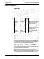
Table 4-6. SFP Default Settings
System Parameters
Default Setting
Touch Scanning
Off
Reporting Method
Coordinate reporting
Touch Mode
Tracking Mode
Add Exit Point Modifier
Off
Report Transfer
Off
Hardware Flow Control
Off
Checking for Touch System Errors
To confirm that the initialization sequence was successful, determine
the status of the touch system by sending the Get_Error_Report (32H)
command. The Error Report that is returned lists any errors detected by
the touch system. Since report transfer has not been enabled yet, the
host must enable it so that the touch system can transmit the Error
Report. This is accomplished by sending the Report_Transfer_On
(44H) command to the touch system before sending the
Get_Error_Report (32H) command.
Touch System Programmer’s Guide
4-9
Chapter 4 - Smart-Frame Protocol
CARROLL TOUCH
The contents of the Error Report vary according to whether the touch
system has a single processor or dual processors.
If the touch system did not detect any errors, the Error Report appears
as follows:
F8 00 FF
Reports no errors for single processor
systems.
F8 00 00 FF
Reports no errors for dual processor
systems.
If the touch system detects errors, the 00 byte is replaced by an error
code count, followed by error codes. These error codes are identified in
the Get_Error_Report (32H) documentation in Appendix A.
If the Error Report is not received by the host, there is a communication
error. Run the initialization sequence again or send the Echo_On (20H)
command to determine the source of the communication problem.
Setting the Reporting Method and Touch
Mode
The host may now complete the initialization sequence and enable
touch system scanning. It should send the appropriate Smart-Frame
Protocol commands to set the desired reporting method and touch
mode, send any other parameters (such as hardware flow control, and
so forth), then send the Touch_Scanning_On (2AH) command.
Touch System Initialization Examples
The following examples represent the recommended initialization
sequences for various touch system hardware configurations.
Using Autobaud/Autoparity
To initialize a touch system that communicates serially and uses
autobaud/autoparity, use the following initialization sequence:
1. Send a 400ms break. You may send a Reset (45H) command
instead, but this only works if the touch system has previously
been set to receive commands at the current baud rate and parity
and is not recommended.
2. Wait one second for the touch system to complete its power-on
testing.
4-10
Touch System Programmer’s Guide
CARROLL TOUCH
Chapter 4 - Smart-Frame Protocol
3. Send five carriage returns (CRs - 0DH) with a 100ms delay after
each CR.
4. Send the Software_Reset (3CH) and delay 100ms.
5. Send the Report_Transfer_On (44H) command, followed by the
Get_Error_Report (32H) command.
6. Read the Error Report sent by the touch system. If the report is
received correctly and indicates no errors, the touch system is
ready to use. If the report is not received correctly, or contains
errors, take the appropriate action.
7. Send the Get_Frame_Size_Report (37H) command.
8. Read the Frame Size Report sent by the touch system. If the frame
size is 223 x 223 (DFH x DFH), you can assume that the touch
system is a guided acoustic wave system. If the frame size is
reported as any other value, you can assume that the touch system
is a scanning infrared system.
Using a Fixed Baud Rate
To initialize a touch system that communicates serially and used a fixed
baud rate, use the following initialization sequence:
1. Send a 400ms break. You may send a Reset (45H) command
instead, but this only works if the touch system has previously
been set to receive commands at the current baud rate and parity
and is not recommended.
2. Wait one second for the touch system to complete its power-on
testing.
3. Send the Software_Reset (3CH) command and delay 100ms.
4. Send the Report_Transfer_On (44H) command, followed by the
Get_Error_Report (32H) command.
5. Read the Error Report sent by the touch system. If the report is
received correctly and indicates no errors, the touch system is
ready to use. If the report is not received correctly, or contains
errors, take the appropriate action.
Using the HBC
To initialize a touch system that uses the modular hardware-based
controller (HBC), use the following initialization sequence:
1. Write to the HBC Hardware Reset Register (Base Address +2).
2. Wait one second for the touch system to complete its power-on
testing.
3. Send the Software_Reset (3CH) command and delay 100ms.
Touch System Programmer’s Guide
4-11
Chapter 4 - Smart-Frame Protocol
CARROLL TOUCH
4. Send the Report_Transfer_On (44H) command, followed by the
Get_Error_Report (32H) command.
5. Read the Error Report sent by the touch system. If the report is
received correctly and indicates no errors, the touch system is
ready to use. If the report is not received correctly, or contains
errors, take the appropriate action.
Using an SBC
Touch systems that include the SBC are unique because they use the
CPU of the host PC to manage the scanning of the frame and reporting
of touch coordinates instead of using a dedicated microprocessor.
The following exceptions to the standard Smart-Frame Protocol exist
for SBC-based touch systems:
•
The scan reporting method is not supported by the SBC. Sending
the Scan_Reporting (22H) command to the SBC has no effect.
•
Sending the Echo_On (20H) command, the Echo_Off (21H)
command, or the Reset (45H) command to the SBC has no effect,
and causes the Invalid Command error to occur.
•
The Hardware_Flow_Control_On (41H) and the Hardware_
Flow_Control_Off (42H) commands apply only to touch systems
that communicate serially, and have no effect when sent to the
SBC.
When using an SBC-based touch system, turning touch scanning on via
the Touch_Scanning_On (2AH) command causes the SBC hardware to
begin issuing hardware interrupts. Turning touch scanning off via the
Touch_Scanning_Off (2BH) command causes the SBC hardware to
stop issuing hardware interrupts. Since the SBC TAPI driver only uses
host CPU time when an interrupt is issued by the SBC hardware,
turning touch scanning off whenever possible releases host CPU time
that would otherwise be used by the SBC TAPI driver for other uses.
Compatibility Issues/Programming Tips
An application or driver that is hard-wired to a typical size or model of
CT touch system may require modification if a different touch system
is used. Applications and drivers that use the Smart-Frame Protocol to
interface to the touch system should be designed to work with all types
and sizes of touch systems that use the Smart-Frame Protocol. This lets
you continue to use the application or driver without modification if a
different size and/or model of CT touch system is used. The following
design rules should be followed.
4-12
Touch System Programmer’s Guide
CARROLL TOUCH
Chapter 4 - Smart-Frame Protocol
Number of Processors Independence
Get_Error_Report (32H) causes an Error Report to be returned that
details the errors for each processor in the touch system. Use the
Get_Configuration_Report (33H) command to get a Configuration
Report that includes the number of processors in the touch system to
properly interpret this report. Do not hard wire the code that interprets
the Error Report to work with a specific number of processors.
Firmware Version Independence
Get_Firmware_Version_Report (34H) causes a Firmware Version
Report to be returned that lists firmware versions for various touch
system components. Do not hard wire the code that interprets the
Firmware Version Report to only work with a specific number of
version reports or a specific firmware version.
Frame Size Independence
If a software calibration and scaling program, as described in this guide,
is used, a change to a touch system with a different size frame simply
requires that the calibration program be run on the new touch system.
The frame size difference is reflected in the calibration parameters, and
the touch application or driver code itself does not need to be modified.
Do not hard wire the touch application or driver to a specific frame size,
since this requires the touch application or driver to be modified if a
different size frame is used.
Touch System Response Time
Independence
The amount of time required for a touch system to process a command
may vary, depending upon the model of the touch system. This, coupled
with the fact that there is no provision for software flow control in the
host-to-touch system direction, means that the input queue of the touch
system could overflow, causing commands to be missed if the touch
system is bombarded with commands at a faster rate than it can process
them. This usually occurs only when a long sequence of initialization
commands is issued at a high baud rate.
To prevent this overrun and loss of command characters:
1. Use a delay of approximately 10 milliseconds between commands
to allow the touch system time to process each command before
the next is sent.
2. Use a lower baud rate.
Touch System Programmer’s Guide
4-13
Chapter 4 - Smart-Frame Protocol
CARROLL TOUCH
Using a baud rate above 2400 baud does not produce any increase in
apparent touch responsiveness. This is due to the fact that the
communication bandwidth required to transmit the four-byte touch
coordinate reports at the typical rate of 30 scans per second is slightly
above 1200 baud. Therefore, using a baud rate above 2400 baud is
unnecessary and merely reduces the noise immunity of the
communication channel while producing no increase in apparent touch
responsiveness.
SFP Timing
The following timing parameters apply to touch systems that use the
Smart-Frame Protocol.
Autobaud/Autoparity Delay Time
During the autobaud/autoparity initialization sequence, a delay of at
least 100 milliseconds must be present between the carriage returns and
after the Software_Reset (3CH) command. This delay is required in
order for the autobaud/autoparity algorithms to work properly.
Maximum Command Completion Time
The maximum amount of time required for a Smart-Frame Protocol
command to be processed and a corresponding report (if any) to be
generated is one second. Touch applications should use at least this
amount of time as their time-out value when awaiting a Smart-Frame
report.
Reset Time/Diagnostics Completion Time
The maximum amount of time required for a touch system that uses the
Smart-Frame Protocol to become ready to begin the autobaud/
autoparity sequence or to receive commands is one second. Touch
applications should either wait at least this amount of time or wait for
some other signal that the touch system is ready to receive commands
(such as the assertion of the Clear To Send (CTS) signal if serial
hardware flow control is used) before beginning the autobaud/
autoparity sequence or sending commands to the touch system.
SFP Programming Examples
The Carroll Touch Driver/Demo Disk contains five short example
programs under the heading of “Programmer’s Guide Programming
Examples.” They demonstrate how to interface directly to
RS-232-based and HBC-based touch systems using the Smart-Frame
4-14
Touch System Programmer’s Guide
CARROLL TOUCH
Chapter 4 - Smart-Frame Protocol
Protocol. Both a polling method and an interrupt-driven method are
shown for each type of touch system. All of these programs were
developed using Borland C. Minor modifications may be required for
other compilers.
The example files are:
CT.H
UART8250.H
RS232POL.C
RS232INT.C
HBCPOL.C
HBCINT.C
Touch System Programmer’s Guide
-
Contains a CT header file.
Contains a 8250 serial UART header file.
Contains an RS-232 polling example.
Contains an RS-232 interrupt example.
Contains an HBC polling example.
Contains an HBC interrupt example.
4-15
Chapter 4 - Smart-Frame Protocol
4-16
CARROLL TOUCH
Touch System Programmer’s Guide
5
Smart-Frame
Protocol II
T
his chapter gives an overview of the Smart-Frame Protocol-II, a
firmware protocol that extends the capabilities of the SFP by
offering support for higher resolution and a z-axis. Explanations of
command formats and report formats are included.
This chapter discusses the following topics:
•
Overview.
•
Types of SFP-II Functions.
•
Functions.
•
Commands.
•
Reports.
•
Error Reporting.
•
Overloaded Functions.
•
Shared Parameters between SFP and SFP-II.
See Appendix B, “Smart-Frame Protocol II Function Reference,” for
the specifications of each Smart-Frame Protocol II function.
Touch System Programmer’s Guide
5-1
Chapter 5 - Smart-Frame Protocol II
CARROLL TOUCH
Overview
The Smart-Frame Protocol II (SFP-II) is a firmware protocol intended
to be the successor to the existing Smart-Frame Protocol firmware
protocol, which was defined in 1985. Driving factors behind the
development of the SFP-II protocol are:
•
The introduction of touch systems using guided acoustic wave
technology, which supports high resolution touch coordinates as
well as z-axis touch coordinates - features not supported by the
existing Smart-Frame Protocol.
•
The need for general and architectural enhancements to the SFP.
SFP-II has been initially implemented on guided acoustic wave
systems, but is designed for and will be implemented on all Carroll
Touch systems.
Extensibility
SFP-II is designed to support true extensibility, allowing features to be
added or removed over time. It does this by providing a standard
mechanism whereby applications or drivers that interface with the
touch system can determine which features the touch system supports.
This mechanism consists of two parts: the touch system can report the
protocol version (not to be confused with the firmware version) to an
application or driver via the Protocol Version Report, and the
application or driver can use the SetReportProperties (21H) command
to request that a Report Properties Report be sent. This report includes
a parameter called FunctionVersion that can be used to determine if a
particular function is supported.
The protocol version number reflects the unique set of features
supported by that version of the protocol. Any time that a feature is
added, removed, or changed in such a way that it would be visible to the
user using the published SFP-II functions, the protocol version number
is incremented.
The protocol version number of the SFP is (retroactively) defined to be
1.0. Note, however, that because the SFP contains no mechanism for
reporting the protocol version number, SFP touch systems do not
actually respond with a Protocol Version Report. Instead, if an
application or driver receives no response when attempting to switch to
SFP-II mode using the SwitchToSFP-II (65H) SFP command, it should
timeout waiting for the command, and then assume that the touch
system only supports SFP (SFP 1.0).
5-2
Touch System Programmer’s Guide
CARROLL TOUCH
Chapter 5 - Smart-Frame Protocol II
Protocol version numbers greater than 1.0 but less than 2.0 will be used
during the development of the SFP-II protocol. When the SFP-II
protocol is complete, that is, when it incorporates the initial set of
desired features, that version of the protocol will be given a version
number of 2.0. Subsequent changes to the protocol will result in
changes to the subminor, minor, or major portions of the protocol
version number, depending upon the extent of the changes.
One of the main purposes for extensibility is to allow properly written
applications and drivers to work with touch systems that support SFP
and touch systems that support SFP-II. A “properly written” application
or driver uses the following sequence of steps during touch system
initialization to determine the protocol version and act accordingly:
1. Initialize the touch system using the common initialization
sequence.
2. Attempt to switch to SFP-II mode by issuing the SwitchToSFP-II
(65H) SFP command.
3. If the touch system does not respond with a Protocol Version
Report within the SFP timeout time (one second), the application
or driver should assume that the touch system supports only the
SFP (SFP 1.0), and use only SFP commands and expect only SFP
reports.
4. If the touch system responds with a protocol version report that
indicates a protocol version number of 2.0 or above, the
application or driver may use all of the standard SFP-II commands
and reports. The application or driver may also (optionally) use
SetReportProperties (21H) command to request Report Properties
Reports to ensure that each command that it uses is supported. This
optional step is recommended if the application uses commands or
reports that were not included in the original SFP-II protocol (SFP
2.0).
In summary, applications or drivers can use the Protocol Version
Report to determine the firmware protocol version. The protocol
version can be used to determine whether the touch system supports
only SFP or SFP and SFP-II. The application or driver may also use the
Protocol Version Report in conjunction with the protocol version
revision history to determine the exact features that the firmware
supports. Finally, for maximum protection against protocol changes,
the application or driver can use the SetReportProperties (21H)
function to ensure that each command that it intends to use is supported.
Touch System Programmer’s Guide
5-3
Chapter 5 - Smart-Frame Protocol II
CARROLL TOUCH
Modal Protocols
The SFP-II is implemented as a modal protocol, meaning that, even if
a touch system supports both the SFP and SFP-II, it can only support
one protocol at a time and, during that time, cannot accept commands
from the other protocol. To switch between protocols, use the
SwitchToSFP-II (65H) SFP command and the SwitchToClassicSFP
(64H) SFP-II function.
Note
The SFP-II protocol currently lacks many necessary features that
are supported in SFP, so it is necessary for the host to switch
between the SFP and SFP-II to access these features. When the
SFP-II protocol specification is complete, it will include all
necessary features, eliminating the need to switch protocols.
Backward Compatibility
Touch systems that implement SFP-II (known as SFP-II aware touch
systems) also implement the existing SFP to ensure backward
compatibility with existing touch systems and to avoid obsoleting the
installed base of touch applications. Backward compatibility means
that:
1. SFP-II aware touch systems may be used with existing
applications that use the SFP without requiring the application to
be modified.
This is possible because the initialization sequence is identical for
both SFP-II aware and non SFP-II aware touch systems, and
because SFP-II aware touch systems power up under SFP and
remain in SFP until explicitly commanded to switch to SFP-II.
2. Applications and drivers may be written to use both SFP-II aware
touch systems and non SFP-II aware touch systems (albeit with
reduced functionality).
This is possible because a mechanism exists whereby applications
and drivers can interrogate the touch system to determine whether
the touch system supports SFP-II. The application or driver may
choose to use the advanced functions of SFP-II or to use only the
SFP.
5-4
Touch System Programmer’s Guide
CARROLL TOUCH
Chapter 5 - Smart-Frame Protocol II
Types of SFP-II Functions
SFP-II functions are currently grouped into four logical categories. The
logical categories are reserved in groups of 16 (10H), with each group
containing functions that have similar purposes.
•
Reset and touch reporting:
GetTouchState (01H)
•
Status reporting:
GetCoordinateRanges (10H)
GetConfiguration (11H)
•
Parameter setting and reporting:
SetTouchModes (20H)
SetReportProperties (21H)
SetReportTransferMode (22H)
•
Mode switching:
SwitchToClassicSFP (64H)
GetProtocolVersion (65H)
Functions
Touch systems that support SFP-II communicate with applications and
drivers via the use of SFP-II functions. Each function consists of a
command and a corresponding report, even if that report is simply a
null report that only returns the report number and the command error
status. The report number is the same as the command number for each
command/report pair.
Each command/report pair may be thought of as corresponding to a
function call in a language such as C, with the command parameters (if
any) representing the parameters that are passed into the function, and
the report parameters (if any) representing the parameters that are
returned by the function.
The host computer sends SFP-II commands to the touch system, and the
touch system responds by sending SFP-II reports to the host. The touch
system must respond with the corresponding SFP-II report packet for
each and every SFP-II command packet that it receives. The host, in
turn, must wait until it receives the corresponding SFP-II report packet
after sending an SFP-II command packet before it can send another
SFP-II command packet.
The host should use a one second timeout when waiting for the report
packet. If the report packet has not arrived after that time, the host
should retry sending the command. If the touch system still does not
Touch System Programmer’s Guide
5-5
Chapter 5 - Smart-Frame Protocol II
CARROLL TOUCH
respond after another timeout period, the host should send enough FFH
bytes to ensure that the touch system’s input buffer overflows, and then
retry the command again. Note that the host could certainly send the
FFH bytes without retrying the command if it so chose. Refer to “Error
Reporting,” later in this chapter, for more details on error handling.
This design greatly simplifies the handling of command and report
packets for the touch system and the host. The touch system cannot
queue up command packets from the host, thus preventing many
potential overrun and timing problems.
Commands
An SFP-II command has the format:
header packetbytecount commandnumber
optionalparameters trailer
header = Defined to be 66H.
packetbytecount
= Length of the command number + the command
parameters (if any) in bytes. For example, a command
with two bytes of parameters has a byte count of 3 (one
byte for the command number and two bytes for the
parameters).
commandnumber
= One byte opcode that identifies the SFP-II command.
Valid opcodes are 00H through BFH.
optionalparameters
= Parameters for the SFP-II command. The maximum
number of parameter bytes is 252 (FCH).
trailer
= Defined to be FFH.
The maximum length of an SFP-II command packet is 256 bytes.
The format for SFP-II commands reflects the fact that SFP-II is a
layered protocol. There are two layers, the validation layer and the
interpretation layer.
5-6
Touch System Programmer’s Guide
CARROLL TOUCH
Chapter 5 - Smart-Frame Protocol II
Validation Layer
The format for SFP-II commands at the validation layer is:
header packetbytecount interpretationlayer
trailer
The validation layer consists of the outer portions of the command
format and “wraps” around the inner portions of the command format,
or the interpretation layer. To detect a valid SFP-II command in the
incoming stream of bytes, the touch system firmware detects the
header, reads the byte count that follows the header, reads the number
of bytes specified by the byte count (the command packet), and verifies
that the following byte is a trailer byte. If the segment of the incoming
byte stream under consideration fits this format, the segment is deemed
to be a valid SFP-II command packet and the command number and
parameters are forwarded to the interpretation layer.
Interpretation Layer
The format for SFP-II commands at the interpretation layer is:
commandnumber optionalparameters
To interpret the command, the touch system firmware first jumps to the
appropriate command handler using a jump table. If the command
number does not correspond to a defined SFP-II command, the
command is deemed invalid and a report is sent to the host with the
command error parameter set to the Invalid Command value.
If the command handler determines that the appropriate number of
parameter bytes for the command is not present, or that one or more of
the parameter bytes are otherwise invalid for the command (parameter
is out of range, not set to a valid value for this particular touch system,
and so forth), the corresponding SFP-II report is sent to the host with
the command error parameter set to indicate the missing or invalid
parameter byte. The parameters that the host sent in the command are
echoed to the host in this report.
If the command handler determines that the appropriate number of
parameter bytes for the command is present and that all of the
parameter bytes are valid for that command, the touch system processes
the command and sends the corresponding SFP-II report back to the
host. The command error parameter is set to the “valid command and
parameters” value to indicate that both the command and parameters
were valid.
Touch System Programmer’s Guide
5-7
Chapter 5 - Smart-Frame Protocol II
CARROLL TOUCH
The bytes within the command packet are indexed beginning at 0 for
the SFP-II command number, and ending at (command packet byte
count - 1) for the last parameter byte. The length of the command
packet is given by the packet byte count from the validation layer.
Example
A simple example of an SFP-II command is the GetTouchState (01)
command, which has one byte of data and no optional command
parameters, is:
66 01 01 FF
A more complex example of a SFP-II command is the imaginary Fubar
command, which expects a one byte parameter (bip) and a two byte
parameter (flap):
66 04 <Fubar> <Bip> <FlapHi> <FlapLo> FF
If the command opcode for Fubar is 27H, and the values of the Bip and
Flap parameters are 18H and 8923H, respectively, the command packet
is as follows:
66 04 27 18 89 23 FF
Reports
An SFP-II report has the format:
header packetbytecount commanderrorstatus
reportnumber optionalreportparameters trailer
header = Defined to be EOH.
packetbytecount
= Length of the report number + the command error status
+ the report parameters (if any) in bytes. For example, a
report with two bytes of parameters would have a byte
count of 4 (one byte for the command number, one byte
for the command error status, and two bytes for the
parameters).
commanderrorstatus
= A one byte parameter that indicates whether the SFP-II
command number and/or the SFP-II command
5-8
Touch System Programmer’s Guide
CARROLL TOUCH
Chapter 5 - Smart-Frame Protocol II
parameters of the SFP-II command packet that solicited
the report were valid.
If the command number and parameters were all valid,
this parameter is 0.
If there was an error associated with one of the command
parameters, this parameter contains a number that points
to the first byte of the parameter that was in error. If there
are multiple parameters with errors, only the first one is
indicated.
If the command number is invalid, this parameter is FFH.
If no SFP-II command packet was associated with this
report (i.e, the report is an unsolicited report), this
parameter is 0. Refer to “Error Reporting,” later in this
chapter, for more information on this parameter.
reportnumber
= One byte opcode that identifies the SFP-II report. Valid
opcodes are 00H through BFH.
optionalreportparameters
= Parameters for the SFP-II report. The maximum number
of parameter bytes is 251 (FBH).
trailer= Defined to be FFH.
The maximum length of an SFP-II report packet is 256 bytes.
The generic report format for SFP-II reports reflects the fact that SFP-II
is a layered protocol. There are two layers, the validation layer and the
interpretation layer.
Validation Layer
The format for SFP-II reports at the validation layer is as follows:
header packetbytecount interpretationlayer
trailer
Note that the validation layer consists of the outer portions of the report
format and “wraps” around the inner portions of the format, or the
interpretation layer. To detect a valid SFP-II report in the incoming
stream of bytes, the host must detect the header, read the byte count that
Touch System Programmer’s Guide
5-9
Chapter 5 - Smart-Frame Protocol II
CARROLL TOUCH
follows the header, read the number of bytes specified by the byte count
(the report packet), and verify that the following byte is a trailer byte.
If the segment of the incoming byte stream under consideration fits this
format, the segment is deemed to be a valid SFP-II report packet and
the command error status, report number, and parameters are forwarded
to the interpretation layer.
Interpretation Layer
The format for SFP-II reports at the interpretation layer is as follows:
commanderrorstatus reportnumber
optionalreportparameters
To interpret the report, the host should first examine the command error
status parameter. If the command error status parameter indicates an
error, the host should take the appropriate action.
The host should then examine the report number. If the report number
does not correspond to a defined SFP-II report, the host should deem
the report invalid.
Finally, the host should examine the report to determine that the
appropriate number of parameter bytes for the report is present. If the
appropriate number is not present, or one or more of the parameter
bytes are otherwise invalid for the report (parameter is out of range and
so forth), the host should deem the report invalid.
If the host determines that all information in the interpretation layer is
valid, the host should process the command.
The bytes within the report packet are indexed beginning at 0 for the
SFP-II report number, and ending at (report packet byte count - 1) for
the last parameter byte. The length of the report packet is given by the
packet byte count that was read during the validation layer.
Example
An example of a report issued in response to a valid SFP-II command,
GetProtocolVersion (command 65), is:
E0 04 00 65 02 12 FF
E0 and FF are the header and footer, respectively. 04 indicates the
report contains four bytes. 00 is the command error status (Cmderr)
and indicates the report is valid. 65 is the report number, which is the
5-10
Touch System Programmer’s Guide
CARROLL TOUCH
Chapter 5 - Smart-Frame Protocol II
command number. The parameters 02 and 12 represent the
ProtocolVersionHi and ProtocolVersionLo bits, indicating protocol
version 2.12.
Reporting Modes
Each SFP-II report has a reporting mode associated with it that
specifies when the report is to be sent. The available reporting modes
are:
Solicited Only Mode
-
The touch system sends the selected
report after receiving the corresponding
command.
Parameter Change Mode-
The touch system sends the selected
report after receiving the corresponding
command and whenever any of the
parameters contained in the report
changes.
Continuous Mode
The touch system sends the selected
report after receiving the corresponding
command and each time that it executes
its main executive loop.
-
Parameter Change Mode and Continuous Mode produce “unsolicited
reports,” because reports are sent by the touch system even though it
has not received a corresponding SFP-II command. The default
reporting mode of most reports is Parameter Change Mode. The
exceptions to this are the Multi Touch State and Raw Touch State
Reports, which are solicited only.
Use the SetReportProperties (21H) function to set the reporting mode
of reports.
Report Transfer Mode
When report transfer is disabled, unsolicited reports are not transferred
from the touch system to the host. Solicited reports continue to be
transferred from the touch system to the host.
When report transfer is enabled, both solicited and unsolicited reports
are transferred.
Use the SetReportTransferMode (22H) function to set the reporting
mode of reports.
Touch System Programmer’s Guide
5-11
Chapter 5 - Smart-Frame Protocol II
CARROLL TOUCH
Error Reporting
SFP-II uses a command error status parameter (Cmderr) to report errors
in commands sent to the touch system. The one-byte parameter is part
of every SFP-II report and indicates whether the SFP-II command
number and/or command parameters were valid.
Note
The use of the Cmderr parameter to indicate unsupported features
is especially useful during the period that the SFP-II specification
is being developed. Features that have been specified but not yet
implemented will be indicated in this manner. The host should
check Cmderr in all reports returned from the touch system to
recognize these unsupported features.
Cmderr has a value of 0 if the command number and parameters are all
valid, or if the report is an unsolicited report.
When an error occurs, the command number and parameter bytes (if
any) that were sent by the host are echoed to the host in the
corresponding report. The touch system does not take any of the actions
and/or change the values of any of the parameters in the command.
Invalid Command Number
When an invalid command number is detected, an SFP-II report packet
is sent with Cmderr set to FF.
For example, if function 93H is undefined and the host sends the
following command:
66 01 93 FF
The touch system responds with the following report:
E0 02 FF 93 FF
The first FF byte is Cmderr and indicates that there is no command
defined with an opcode value of 93H.
If function 94H is undefined and the host sends the following
command:
66 04 94 01 02 03 FF
5-12
Touch System Programmer’s Guide
CARROLL TOUCH
Chapter 5 - Smart-Frame Protocol II
The touch system responds with the following report:
E0 05 FF 94 01 02 03 FF
The first FF byte is Cmderr and indicates that there is no command
defined with an opcode value of 94H. Note that the parameters that
were sent with the invalid command packet (01 02 03) are returned
along with the invalid command number.
Invalid Parameter Value
When the parameter number is out of range, an SFP-II report packet is
sent with Cmderr containing a number that points to the first byte of the
parameter that was in error. If there were multiple parameters with
errors, only the first one is indicated.
If the host sends the SetTouchModes (20H) command as follows:
66 04 20 01 04 03 FF
The touch system responds with the following report:
E0 05 02 20 01 04 03 FF
The 02 byte is Cmderr and indicates that the second parameter is out of
range. (The value of 04 for TouchStateReportType is not among the
valid values of 01, 02, or 03.) Since the 04 byte is out of range, the error
results and is reported in Cmderr. The third parameter is also out of
range. This parameter is the TouchReportingMode parameter, which
has valid values of 00, 01, and 02. The 03 byte is out of range.
However, this is not reported to the host because Cmderr only reports
the first invalid parameter if multiple parameters are invalid.
Unsupported Feature
When a parameter value requests an option that the particular firmware
implementation does not support, an SFP-II report packet is sent with
Cmderr containing a number that points to the first byte of the
parameter that was in error. If there were multiple parameters with
errors, only the first one is indicated.
Suppose the host sends the SetTouchModes (20H) command as follows
to (1) enable touch detection; (2) set the TouchStateReportType to the
Multi Touch State Report; and (3) set the Touch Reporting Mode to
Continuous:
Touch System Programmer’s Guide
5-13
Chapter 5 - Smart-Frame Protocol II
CARROLL TOUCH
66 04 20 01 02 02 FF
If the particular firmware implementation in the touch system does not
support the MultiTouchState value of the TouchStateReportType
parameter (the first 02H byte in the command), the touch system
responds with the following report:
E0 05 02 20 01 02 02 FF
The 02 byte is Cmderr and indicates that the second parameter is in
error. This parameter is the TouchStateReportType parameter. The
value of 02H is a valid value for this parameter and represents a request
by the host that the touch data be returned using the Multi Touch State
Report. However, since this particular firmware does not support the
MultiTouchState reporting method, the touch system returns the error
in Cmderr to indicate this to the host.
Invalid Byte Count
The touch system reports an invalid byte count if it reads the number of
bytes specified by the byte count and the next byte received is not a
command packet trailer byte.
Note that this means that if the number of bytes received after the byte
count is less than the byte count, no error is generated until enough
additional bytes are received to match the byte count or the touch
system’s input buffer overflows. The touch system does not use any
sort of timeout technique if it receives fewer bytes than expected.
This error also occurs if the touch system’s input buffer overflows
while it is attempting to read the number of bytes specified by the byte
count.
When an invalid byte count is detected, an SFP-II report packet is sent
with the Cmderr parameter set to FEH and the SFP-II report number set
to the command number.
For example, suppose the host sends the following command:
66 04 20 01 04 03 FF
Due to noise on the serial line, the touch system actually receives an
extra byte after the first parameter as follows:
66 04 20 01 86 04 03 FF
5-14
Touch System Programmer’s Guide
CARROLL TOUCH
Chapter 5 - Smart-Frame Protocol II
The touch system responds with the following report:
E0 06 FE 20 01 86 04 03 FF
FE is the Cmderr parameter and indicates that a byte count mismatch
error occurred. 20 is the ReportNumber parameter, and the following
four bytes echo the parameters that the touch system received.
As a second example, suppose the touch system has an input buffer size
of 32 bytes and the host sends the following, lengthy, incorrect
command:
66 50 FA 01 02 03 ... 4F FF
The touch system reads bytes until its input buffer overflows, then
responds with the following report:
E0 06 FE FA 01 02 03 ... 1D FF
FE is the Cmderr parameter and indicates that a byte count mismatch
error occurred. The following 30 bytes echo the command number and
parameters that the touch system received before the input buffer
overflowed.
For a complex example, suppose the touch system has an input buffer
size of 32 bytes and the host sends the command as follows:
66 04 20 01 04 03 FF
Due to noise on the serial line, the touch system actually receives a
value of 40H (64 decimal) for the byte count instead of 04H as follows:
66 40 20 01 04 03 FF
The touch system reads all seven bytes of the command and places
them in its input buffer. No report is sent because the touch system is
expecting a command that is 64 bytes in length (not counting the
header, byte count and trailer), but only 5 of the 64 bytes have arrived
(the command number, the three parameter bytes, and the trailer, which
the touch system interprets as byte 5 of the 64 bytes that it expects to
receive).
The host can then wait until the command completion timeout time of
one second has elapsed, and then re-send the command. The seven
bytes contained in the command are interpreted by the touch system as
bytes 6 through 12 of the 64 bytes that it is expecting, and it again sends
Touch System Programmer’s Guide
5-15
Chapter 5 - Smart-Frame Protocol II
CARROLL TOUCH
no report. At this point, there are 14 bytes in the input buffer, with 18
bytes remaining.
If the host repeats the timeout and re-send cycle three more times, the
input buffer overflows when the third command is sent, and the touch
system responds with the following report:
E0 06 FE 20 01 04 03 FF 66 04 20 01 04 03 FF 66
04 20 01 04 03 FF 66 04 20 01 04 03 FF 66 04 20
01 FF
FE is the Cmderr parameter and indicates that a byte count mismatch
error occurred. The following 30 bytes echo the command number and
parameters that the touch system received before the input buffer
overflowed. The touch system is now looking for a new command, and
if the host sent the command once more, the touch system would
receive it, process it, and return a report (presuming no error occurred
in sending this latest command).
The time to re-synchronize this entire sequence would be a little over
four seconds - the original command timeout (one second) plus three
retry timeouts (one second each). The fourth retry would not result in a
timeout because the touch system would send the report that contained
the bytes read.
The host need not wait for enough timeout and re-send cycles to fill the
input buffer, however. The host can accelerate re-synchronization by
issuing enough FFH bytes to flush the touch system’s input buffer. This
forces the input buffer to overflow and causes the touch system to begin
looking for a new command. For example, if the host had used this
method after the first report timeout had occurred, the touch system
would have responded with the following report:
E0 06 FE 20 01 04 03 FF FF FF FF FF FF FF FF FF
FF FF FF FF FF FF FF FF FF FF FF FF FF FF FF FF
FF FF
FE is Cmderr and indicates that a byte count mismatch error occurred.
The following 30 bytes echo the command number and parameters, as
well as the flushing FFHs that the touch system received before the
input buffer overflowed. The touch system is now looking for a new
command, and if the host sent the command once more, the touch
system would receive and process it, and return a report (presuming no
error occurred in sending this latest command). With this approach, the
time to re-sync is a little over one second (the timeout for only the
original command).
5-16
Touch System Programmer’s Guide
CARROLL TOUCH
Chapter 5 - Smart-Frame Protocol II
Not Enough Parameters
If the number of command parameters is less than the number of
command parameters expected for the command, an SFP-II report
packet is sent with Cmderr pointing to the location of the first missing
parameter (the trailer).
Note that this case differs from the invalid byte count case. In this case,
the command packet byte count is consistent with the total number of
bytes in the command number and parameters, there just weren’t
enough parameters.
If the host sends the SetTouchModes (20H) command as follows to
enable touch detection and set the TouchStateReportType to the Multi
Touch State Report, but leaves off the required third parameter (the
TouchReportingMode parameter):
66 03 20 01 02 FF
The touch system responds with the following report:
E0 04 03 20 01 02 FF
The 03 byte is Cmderr and indicates that a third parameter was
expected but not present.
Too Many Parameters
If the number of command parameters is greater than the number of
command parameters expected for the command, an SFP-II report
packet is sent with Cmderr pointing to the location of the first extra
parameter.
Suppose the host sends the SetTouchModes (20H) command as follows.
The first three parameters correctly enable touch detection (01), set the
TouchStateReportType to the Multi Touch State Report (02), and set
the TouchReportingMode to Continuous (02). However, an erroneous
fourth parameter (04) is also included:
66 05 20 01 02 02 04 FF
The touch system responds with the following report:
E0 06 04 20 01 02 02 04 FF
The 04 byte is Cmderr and indicates that an extra parameter (the fourth
parameter) was present but not expected.
Touch System Programmer’s Guide
5-17
Chapter 5 - Smart-Frame Protocol II
CARROLL TOUCH
Overloaded Functions
Some SFP-II functions are overloaded in a manner similar to the way
that C++ supports overloaded functions.
An overloaded function is a function that is normally used to set the
values of some parameters, but can also be used to get the values of the
same parameters.
•
To set the parameter values, the host sends the complete command
including all parameters. The touch system sets the parameters
using the values sent by the host, and returns a report that contains
the resulting values for the parameters.
•
To get the parameter values, the host sends only the command
number with none of the parameter values present or a subset of
the parameter values present, depending on the function definition.
The touch system returns a report that contains the parameter
values.
If the host sends a command that includes the command number and a
partial list of parameters, it is an illegal action and an invalid parameter
error is returned in Cmderr.
For example, to get the current touch values using the SetTouchModes
(20H) command, the host sends the command as follows:
66 01 20 FF
The touch system responds with the following report:
E0 05 00 20 01 01 00 FF
This report indicates no errors in Cmderr and reports the values for the
three parameters defined for the function that were in effect when the
command was sent (01, 01, and 00). No parameter values were
changed.
However, to set the touch values using the SetTouchModes (20H)
command, the host sends the command as follows:
66 04 20 01 01 01 FF
The touch system responds with the following report:
E0 05 00 20 01 01 01 FF
5-18
Touch System Programmer’s Guide
CARROLL TOUCH
Chapter 5 - Smart-Frame Protocol II
This report indicates no errors in Cmderr and reports the values for the
three parameters defined for the function after the parameter values
were changed as a result of the host sending the command (three 01
values).
If the host sends a partial list of parameters for the SetTouchModes
(20H) command as follows:
66 02 20 00 FF
The touch system responds with the following report:
E0 03 02 20 00 FF
This report indicates that the second parameter byte was erroneous via
Cmderr (the 02 byte) and echoes the parameters that the host sent. A
Cmderr value of 02H indicates that the touch system expected more
parameters than were actually received.
Shared Parameters between SFP and SFP-II
Most global parameters (that is, parameters that are not associated with
a particular function) in SFP and SFP-II are independent of one another.
However, some global parameters are shared between SFP and SFP-II
and maintain their value when the protocol changes.
Because touch systems that support SFP and SFP-II power up in the
SFP, shared parameters have an SFP default value but no SFP-II default
value. The initial value of shared parameters at the time that the touch
system is switched to the SFP-II is equivalent to the value of the
corresponding SFP parameter at that time.
The global parameters that are currently shared include Touch
Detection and Report Transfer.
Touch Detection
In the SFP, the Touch Scanning parameter is enabled and disabled via
the Touch_Scanning_On (2AH) and Touch_Scanning_Off (2BH) SFP
commands and is reported in the Touch Scanning parameter of the
Get_State_Report (47H) SFP command.
In SFP-II, the Touch Detection parameter is set and reported via the
TouchDetection parameter of the SFP-II function.
Touch System Programmer’s Guide
5-19
Chapter 5 - Smart-Frame Protocol II
CARROLL TOUCH
Report Transfer
The method of transferring reports differs slightly between SFP and
SFP-II. In SFP, turning Report Transfer off disables all reports, both
solicited and unsolicited. In SFP-II, setting the ReportTransferMode
parameter to disabled inhibits unsolicited reports but does not inhibit
solicited reports.
In the SFP, the Report Transfer parameter is enabled and disabled via
the Report_Transfer_On (44H) and Report_Transfer_Off (43H) SFP
commands and is reported in the Report Transfer parameter of the
Get_State_Report (47H) SFP command.
In SFP-II, the ReportTransferMode parameter is set and reported via
the ReportTransferMode parameter of the SetTouchModes (20H)
SFP-II function.
If Report Transfer is disabled when the touch system is switched to
SFP-II, any SFP reports that are pending at that time are sent before
the SFP-II Protocol Version Report is sent. The Report Transfer
parameter remains set to disabled.
Note
The Report Transfer shared parameter is implemented in the GW
DSP Serial Controller in a different manner from that described
here because the SetReportTransferMode (22H) SFP-II function is
not implemented on this controller. The ReportTransfer parameter
is shared as described, but when the controller is switched from
SFP mode to SFP-II mode, the ReportTransfer shared parameter is
set to enabled. When the controller is switched from SFP-II back
to SFP, the ReportTransfer shared parameter does not change
value.
5-20
Touch System Programmer’s Guide
6
Touch
Application
Program Interface
(TAPI)
his chapter includes an overview of the TAPI software functions,
the specifications for each function, TAPI driver installation and
initialization, and programming examples.
T
The chapter discusses the following topics:
•
Overview.
•
Installing a TAPI Driver.
•
Determining if a TAPI Driver Is Installed.
•
Calling TAPI Functions.
•
Touch System Initialization Using a TAPI Driver.
•
TAPI Programming Examples.
See Appendix C, “TAPI Function Reference,” for the specifications of
each TAPI function.
Touch System Programmer’s Guide
6-1
Chapter 6 - Touch Application Program Interface (TAPI)
CARROLL TOUCH
Overview
The Touch Application Program Interface (TAPI) is a set of software
functions that lets an application communicate with a Carroll Touch
touch system using the Smart-Frame Protocol without interfacing
directly to the hardware. Using the TAPI interface protocol yields the
following benefits:
•
An application that interfaces to a TAPI driver is independent of
the touch system hardware. Each touch system hardware
configuration has a TAPI driver, and all of these TAPI drivers
share a common interface (the TAPI interface). As a result, an
application that uses TAPI may be used with various touch system
hardware configurations without modification by simply loading
the appropriate TAPI driver.
•
It is generally easier to write an application that uses TAPI
software interrupt calls to communicate with the touch system than
to write an application that interfaces directly to the touch system
hardware.
The TAPI interface does not include support for calibration or touch
coordinate scaling. These two functions must be performed by the
touch application itself, just as in touch applications that interface
directly to the touch system hardware.
There are three TAPI drivers:
•
Software-based controller (SBC) driver.
•
Hardware-based controller (HBC) driver.
•
RS-232 controller driver.
TAPI driver is a generic term used to describe all three drivers. Each
TAPI driver is a terminate-and-stay-resident (TSR) program that makes
it possible to use the touch system via a software interrupt rather than
by directly accessing the touch system hardware.
The SBC driver must be loaded to use a touch system that uses the SBC.
The SBC is unable to use the Smart-Frame Protocol directly because
the SBC has no processor on board. Use of the HBC or RS-232 drivers
with touch systems that use the HBC or RS-232 controller is optional,
since the application may interface directly to the HBC or RS-232
controller using the Smart-Frame Protocol.
The TAPI drivers run on an IBM or IBM-compatible PC. Each TAPI
driver communicates with any Carroll Touch touch system or controller
6-2
Touch System Programmer’s Guide
CARROLL TOUCH
Chapter 6 - Touch Application Program Interface (TAPI)
that recognizes the Smart-Frame Protocol and communicates either
serially through a comm port or directly through the PC bus.
Installing a TAPI Driver
To install a TAPI driver, simply run the executable driver file with
additional command line parameters, if appropriate, from the DOS
command line. This loads the driver into memory as a TSR program.
SBC Driver
If you have set the I/O address or the interrupt number parameter of the
SBC to values other than the default parameters, or if you are using a
touch frame that has a different number of x-axis or y-axis beams than
the default, you must provide the correct values for these parameters on
the command line when installing the SBC driver.
The SBC driver command line has the following syntax:
SBC options
The available options are:
U
= Uninstalls the driver.
An
= I/O address. n may range from 200H to 3F0H. The
default is 300H.
In
= Interrupt number override. n may be 2, 3, 4, 5, or 7. The
default is 7.
Xn
= Number of x beams on frame. The default is 40.
Yn
= Number of y beams on frame. The default is 30.
Sn
= TAPI software interrupt. n may be the number of any
unused software interrupt. The default is 55H.
The command line is case insensitive and the command line parameters
may be arranged in any order. For example, to install an SBC driver
using an I/O address of 320H, interrupt 5, and 30 x-beams and 20
y-beams, you can type either:
SBC A320 I5 X30 Y20
or
sbc i5 x30 a320 y20
Touch System Programmer’s Guide
6-3
Chapter 6 - Touch Application Program Interface (TAPI)
CARROLL TOUCH
HBC Driver
If you have set the I/O address or the interrupt number parameters of
the HBC to values other than the default parameters, you must provide
the correct values for these parameters on the command line when
installing the HBC driver.
The HBC driver command line has the following syntax:
HBC options
The available options are:
U
= Uninstalls the driver.
An
= I/O address. n may range from 200H to 3F0H. The
default is 300H.
In
= Interrupt number. n may be 2, 3, 4, 5, or 7. The default
is 7.
Sn
= TAPI software interrupt. n may be the number of any
unused software interrupt. The default is 55H.
The command line is case insensitive and the command line parameters
may be arranged in any order. For example, to install an HBC driver
using an I/O address of 340H, hardware interrupt 2, and software
interrupt 57H, you can type either:
HBC A340 I2 S57
or
hbc i2 a340 s57
RS-232 Driver
If you have set the baud rate or parity parameters of the RS-232
controller board to values other than the default values of
autobaud/autoparity, or if you are using an RS-232 port other than the
default value of COM1, you must provide the correct values for these
parameters on the command line when installing the RS-232 driver.
The RS-232 driver command line has the following syntax:
RS232 options
The available options are:
6-4
Touch System Programmer’s Guide
CARROLL TOUCH
Chapter 6 - Touch Application Program Interface (TAPI)
U
= Uninstalls the driver.
Cn
= Serial port. n may be 1 or 2. The default is 1. If the A and
I parameters are used, the C parameter is ignored.
Bn
= Baud rate. n may be 3, 12, 24, 48, or 96. The default is
48.
Pn
= Parity. n may be E (even), O (odd) or N (none). The
default is N.
Sn
= TAPI software interrupt. n may be any unused software
interrupt. The default is 55H.
An
= I/O address override. n may range from 0H to FFFFH.
The A and I parameters must be used together. An error
condition occurs if one override parameter is used
without the other being present.
In
= Interrupt number override. n may be 2, 3, 4, 5, 6, or 7.
The A and I parameters must be used together. An error
condition occurs if one override parameter is used
without the other being present.
The command line is case insensitive and the command line parameters
may be arranged in any order. For example, to operate the RS-232
controller at a baud rate of 4800 with no parity through serial
communication port 1, you can type either:
RS232 C1 B48 PN
or
rs232 b48 c1 pn
If you wish to use the RS-232 driver with a serial port that uses a base
I/O address and/or interrupt number other than the standard values of
3F8H and 4 for COM1 or 2F8H and 3 for COM2, you may use the A
and I parameters to override the default values.
Touch System Programmer’s Guide
6-5
Chapter 6 - Touch Application Program Interface (TAPI)
CARROLL TOUCH
Error Messages
Table 6-1 defines the error messages and meanings for the TAPI
drivers.
Table 6-1. TAPI Error Messages and Explanations
6-6
Message:
Invalid command line parameter.
Valid command line parameters are:
Meaning:
The command line syntax is invalid. The installation
process is aborted.
Message:
A CT driver is already installed at
software interrupt xxH.
Meaning:
A CT driver has been previously installed on the same
software interrupt. xxH denotes the software interrupt.
The TAPI driver looks only for the string CT DRIVER
-. It does not look for a specific type of driver.
Message:
Communication error - unable to send
command.
Check that the touch system is
properly connected.
Meaning:
The TAPI driver could not initialize the touch system
because the driver could not send commands to the
touch system. A timeout occurred while attempting to
transmit the command.
Message:
Communication error - report expected
but not received.
Check that the touch system is
properly connected.
Meaning:
The TAPI driver could not initialize the touch system
because a report that was expected was not received. A
timeout occurred while waiting for the report.
Message:
The selected RS-232 serial port was
not found.
Meaning:
The RS-232 driver could not initialize the touch system
because the driver could not find the specified serial
port.
Touch System Programmer’s Guide
CARROLL TOUCH
Chapter 6 - Touch Application Program Interface (TAPI)
Table 6-1. TAPI Error Messages and Explanations (Continued)
Message:
TAPI driver installation failed.
Meaning:
This error message accompanies other error messages
and indicates that installation was aborted due to the
stated condition.
Message:
Communication error - report expected
but not received.
Check that the touch system is
properly connected.
Meaning:
The TAPI driver could not initialize the touch system
because a report that was expected was not received. A
timeout occurred while waiting for the report.
Message:
No TAPI driver resident at software
interrupt XXH. Uninstall aborted.
Meaning:
An attempt is made to uninstall a TAPI driver at
software interrupt XXH, but no TAPI signature is
detected at that software interrupt.
Message:
The I/O Address Override (a) and
Interrupt Number override (i)
parameters must both be present in
order to override the I/O address and
interrupt number.
Meaning:
One override parameter is present without the other.
Determining if a TAPI Driver Is Installed
An application program may determine if a TAPI driver is installed by
performing a string compare starting at the address pointed to by the
TAPI software interrupt vector +2. For all TAPI drivers, the first 9
characters read CT DRIVER. The type of driver is identified by an
additional string:
CT DRIVER - SBC
CT DRIVER - HBC
CT DRIVER - 232
Identifies an SBC driver.
Identifies an HBC driver.
Identifies an RS-232 driver.
Calling TAPI Functions
To call a TAPI function, load the registers as described in the “Call
with” sections for the TAPI functions described in Appendix C. Then,
Touch System Programmer’s Guide
6-7
Chapter 6 - Touch Application Program Interface (TAPI)
CARROLL TOUCH
call the TAPI driver software interrupt and read the registers as
described in the “Returns” section for that function.
The following example illustrates how to call TAPI functions:
int SendSmartFrameCommand (char command, int
TAPI_sw_int)
{
union REGS regs;
regs.x.ax = 1;
regs.h.bh = 0;
regs.h.bl = 0x32;
int86 (0x55, ®s, ®s);
if (regs.x.cx)
return (1);
return (0);
} /*
SendSmartFrameCommand
*/
Touch System Initialization Using a TAPI Driver
To initialize the touch system using a TAPI driver, send the following
functions and commands in this order:
1. Call Reset (0).
2. Call SendCommand (1), with the Software_Reset (3CH) as the
Smart-Frame command (BL = 3CH). If SendCommand returns a
nonzero value in CX, abort the routine.
3. Wait at least 100 ms.
4. Call SendCommand (1), with Report_Transfer_On (44H) as the
Smart-Frame command (BL = 44H).
5. Call SendCommand (1), using Get_Error_Report (32H).
6. Call GetReports (2), which loads the report into the report buffer
pointed to by BX and DX.
7. Read the Error Report out of the buffer. If there are no errors, the
report reads F8 00 FF.
At this point you may set the desired touch mode using SendCommand
(1) with the appropriate Smart-Frame Protocol command, then turn on
scanning by using SendCommand (1) with a Touch_Scanning_On
(2AH) command. The touch system is now initialized.
6-8
Touch System Programmer’s Guide
CARROLL TOUCH
Chapter 6 - Touch Application Program Interface (TAPI)
TAPI Programming Examples
The CT Driver/Demo Disk contains three short example programs
under the heading of “Programmer’s Guide Programming Examples.”
They demonstrate how to interface to RS-232-based and HBC-based
touch systems via a TAPI driver using the Smart-Frame Protocol. Both
a polling method and an interrupt-driven method are shown for each
type of touch system. All of these programs were developed using
Borland C. Minor modifications may be required for other compilers.
The example files are:
CT.H
TAPIPOL.C
TAPIINT.C
Touch System Programmer’s Guide
Contains a Carroll Touch header file.
Contains a TAPI polling example.
Contains a TAPI interrupt example.
6-9
Chapter 6 - Touch Application Program Interface (TAPI)
6-10
CARROLL TOUCH
Touch System Programmer’s Guide
7
CTKERN
his chapter describes the features and capabilities of the CTKERN
driver, as well as its installation procedures and parameters. It also
discusses the operation of the CTKERN calibration program
(CALIB.EXE).
T
This chapter discusses the following topics:
•
Overview.
•
Calibration.
•
Scaling.
•
Touch Reporting.
•
Calibration and Scaling Examples.
•
Temporal Filter.
•
Methods for Interfacing CTKERN and an Application Program.
•
Loading the CTKERN Driver.
•
Determining if the CTKERN Driver Is Installed.
•
Calling CTKERN Functions.
•
CALIB.EXE.
•
CALIB.DAT.
•
CTKERN Programming Examples.
See Appendix D, “CTKERN Function Reference,” for the
specifications of each CTKERN function.
Touch System Programmer’s Guide
7-1
Chapter 7 - CTKERN
CARROLL TOUCH
Overview
The CTKERN driver communicates with the touch system using the
TAPI driver appropriate for the touch system, and with the application
program using the CTKERN functions, which are accessed via a
software interrupt.
CTKERN is a DOS driver that offers the following features:
•
Calibration support, including multiple calibrations to allow for
monitors that do not maintain a constant image size when
displaying multiple video modes.
•
Touch coordinate scaling support, including multiple sets of
scaling parameters to automatically support multiple video modes.
•
Easy-to-use touch state reporting.
•
Support for user-installable touch event handlers for
interrupt-driven applications.
•
Uninstall capability.
The application software may not issue TAPI function calls while
CTKERN is loaded. In fact, when CTKERN loads, it reads the TAPI
software interrupt vector, saves it, and uses it to call the TAPI driver
instead of the software interrupt. The TAPI software interrupt is
replaced by a pointer to a return from interrupt instruction within
CTKERN, blocking any calls to TAPI. The return from interrupt
instruction is followed by a NOP and the CT DRIVER - string, so that
the driver detection mechanism continues to indicate an installed TAPI
driver at the TAPI software interrupt. When CTKERN is unloaded, it
replaces the TAPI software interrupt vector with the value that was
saved, re-enabling calls to TAPI.
The overall relationship between the touch hardware, the TAPI drivers,
the CTKERN driver, and the application software is illustrated in
Figure 7-1.
Calibration
CTKERN allows up to ten sets of video mode specific calibration
parameters. By using multiple calibrations, CTKERN can allow for
monitors that do not maintain a constant image size when displaying
multiple video modes. One of these sets is designated as the default
calibration.
There are three options for calibration: disabled, fixed, and automatic.
If calibration is disabled, the touch coordinates reported by CTKERN
7-2
Touch System Programmer’s Guide
CARROLL TOUCH
Chapter 7 - CTKERN
Application Software
(CTKERN function calls)
(CTKERN User Event Handler)
CTKERN Driver
(TAPI function calls)
(TAPI User Event Handler)
TAPI Driver
(SBC, HBC, RS-232)
(Serial Xmit or I/O Ports)
(Hardware Interrupt)
Touch Hardware
(SBC, HBC, RS-232)
Figure 7-1. Touch System to Application Communication
are not calibrated. If fixed calibration is selected, the default calibration
is always used, regardless of the BIOS video mode being used. If
automatic calibration is selected, CTKERN intercepts BIOS Int 10H
and watches for SetVideoMode (0). When a SetVideoMode function
occurs, CTKERN switches to the calibration parameters for that video
mode if they exist. If no calibration exists for that video mode,
CTKERN switches to the default calibration parameters.
SetCalibrationParameters (4) may also be used to set the calibration
parameters to arbitrary values that are not related to any calibration
table entry.
CTKERN attempts to read a file of calibration parameters (stored, by
default, in CALIB.DAT) when it is loaded. This file is created by
CALIB.EXE, the CTKERN calibration program, described later in this
chapter. If no calibration file is present or if the calibration file contains
multiple default calibrations, CTKERN does not load, but instead prints
an appropriate error message.
The CTKERN internal table of calibration parameters may be read or
modified while CTKERN is loaded by calling
GetCalibrationTableEntry (7) or SetCalibrationTableEntry (6),
respectively.
Touch System Programmer’s Guide
7-3
Chapter 7 - CTKERN
CARROLL TOUCH
Scaling
CTKERN has the ability to scale the touch coordinates to a
user-defined coordinate system. There are three options for scaling:
disabled, fixed, and automatic.
If scaling is disabled, the touch coordinates reported by CTKERN are
not scaled.
If fixed scaling is selected, the touch coordinates reported by CTKERN
are scaled using 0, 0 for the upper left x and y scaling parameters and
(Xres - 1, Yres - 1) from the calibration parameters of the default
calibration entry for the lower right x and y scaling parameters, then are
passed on to the application program. If no calibration entry is marked
as the default, the Xres, Yres values of the first calibration entry
(calibration table index 0) are used.
If automatic scaling is selected, the touch coordinates reported by
CTKERN are scaled using 0, 0 for the upper left x and y scaling
parameters and (Xres - 1, Yres - 1) from the calibration parameters for
the currently selected BIOS video mode for the lower right x and y
scaling parameters, then are passed on to the application program. The
driver determines the video mode by intercepting calls to BIOS mode
10H function 0 (Set Video Mode). If an entry in the table of calibration
parameters that corresponds to that video mode exists, the Xres, Yres
values of those calibration parameters are used. If no such entry exists,
the Xres, Yres values of the default calibration parameters are used. If
no calibration entry is marked as the default, the Xres, Yres values of
the first calibration entry (calibration table index 0) are used.
SetScalingParameters (9) may also be used to set the scaling
parameters to arbitrary values that are not related to the Xres and Yres
parameters in any calibration table entry.
CTKERN has the ability to scale the z-axis pressure parameter returned
by touch systems that support z-axis pressure detection. There are only
two options for z-axis scaling: disabled and enabled. When z-axis
scaling is disabled, the raw z-axis parameter reported by the touch
system is reported by CTKERN. If z-axis scaling is enabled, the z-axis
parameter reported by the touch system is scaled linearly within the
range defined by user-definable minimum and maximum pressure
values.
7-4
Touch System Programmer’s Guide
CARROLL TOUCH
Chapter 7 - CTKERN
Touch Reporting
The application program may get touch reporting information from
CTKERN either by calling GetTouchState (1) that returns the current
touch state, or by setting up a user event handler that is called whenever
the touch state changes by using SetUserEventHandlerMode (23).
Possible touch states are:
NT
Not touched, with scaled (if enabled), calibrated (if enabled)
coordinates of the last place the screen was touched. If the
screen has not been touched since the driver was last loaded
or reset, the coordinates returned are 0, 0.
TO
Touched, with scaled (if enabled), calibrated (if enabled)
coordinates of where the screen is currently being touched.
NC
Non-contiguous.
The touch state is automatically maintained by CTKERN using an
interrupt-driven background process.
CTKERN also includes SetTouchState (2) to manually set the touch
state to a user-specified state. This can be useful for debugging and so
forth.
Calibration and Scaling Examples
Because the calibration and scaling modes of CTKERN may be
independently set, there are four possible combinations of calibration
and scaling modes, as shown in Figure 7-2 through 7-5:
Figure 7-2:
Calibration mode = Fixed or automatic
Scaling mode
= Fixed or automatic
Figure 7-3:
Calibration mode = Fixed or automatic
Scaling mode
= Disabled
Figure 7-4:
Calibration mode = Disabled
Scaling mode
= Fixed or automatic
Figure 7-5:
Calibration mode = Disabled
Scaling mode
= Disabled
Each figure illustrates the touch coordinates that are returned for that
particular combination of calibration and scaling modes. The touch
Touch System Programmer’s Guide
7-5
Chapter 7 - CTKERN
CARROLL TOUCH
active area is indicated by the striped area. The range of touch
coordinates that are returned by a touch within the touch active area is
indicated by the coordinate pairs at the upper left and lower right
corners of either the touch active area defined during calibration (the
inner rectangle) or the touch active area of the touch system (the outer
rectangle).
The examples all assume the following:
•
A touch frame with 80 logical x-axis coordinates numbered 0 - 79,
and 60 logical y-axis coordinates numbered 0 - 59.
•
Scaling parameters set to match a 640 x 480 VGA display.
Upper left x
Upper left y
Lower right x
Lower right y
•
=0
=0
= 639
= 479
Touches at (5, 4) and (74, 55) for the upper left and lower right
corners, respectively, during calibration.
The numbers on the outside of the outer rectangle indicate the logical
touch coordinates along each axis.
0
4
0
5
74
79
(0,0)
55
(639,479)
59
Figure 7-2. Calibration Mode Fixed or Automatic and Scaling Mode
Fixed or Automatic
7-6
Touch System Programmer’s Guide
CARROLL TOUCH
Chapter 7 - CTKERN
0
0
4
5
74
79
(0,0)
55
(69,51)
59
Figure 7-3. Calibration Mode Fixed or Automatic and Scaling Mode
Disabled
(0,0)
0
0
5
74
79
4
55
59
(639,479)
Figure 7-4. Calibration Mode Disabled and Scaling Mode Fixed or
Automatic
Touch System Programmer’s Guide
7-7
Chapter 7 - CTKERN
CARROLL TOUCH
(0,0)
0
0
5
74
79
4
55
59
(79,59)
Figure 7-5. Calibration Mode Disabled and Scaling Mode Disabled
Temporal Filter
When enabled, the temporal filter acts much like a low pass filter in the
time domain for all touch state transitions. You must define two
parameters, Spatial Filter Box Size and Temporal Filter Time.
When the stylus touches the screen, the center of the spatial filter box
is set to the coordinates where the screen was first touched. The touch
state is set to “touched” only after the stylus has remained in the spatial
filter box for the length of time specified by the Temporal Filter Time
parameter.
If the stylus moves beyond the spatial filter box, the Temporal Filter
Time and the center of the spatial filter box are reset. The coordinates
are not updated until the stylus has once again remained in the spatial
filter box for the Temporal Filter Time. The coordinates associated with
the “not touched” state are still the exit point, but the touch state
becomes “not touched” only after the stylus is out of the screen for the
Temporal Filter Time. The touch state is set to “non-contiguous” only
after a non-contiguous stylus has been in the touch screen for the
Temporal Filter Time.
7-8
Touch System Programmer’s Guide
CARROLL TOUCH
Chapter 7 - CTKERN
Methods for Interfacing CTKERN and an Application
Program
Application programs generally use either an interrupt mode or a
polling mode to retrieve touch information.
Polling Mode
Using the polling mode, the application program periodically checks
the touch state using GetTouchState (1). If the application does this at
a comparatively rapid rate, touch state information is current. If the
application polls at a slower rate, there is danger of missing transitions
in the touch state during the time between polls.
Interrupt Mode
In the interrupt mode, the application program installs a CTKERN user
event handler (UEH) using SetUserEventHandler (7). Whenever the
touch state changes, CTKERN places the touch state parameters in the
CPU registers and calls the application’s UEH. The application’s UEH
then reads the parameters from the registers and copies them into
variables within the application. The application program should keep
the CTKERN UEH as short as possible, as touch information may be
lost if the screen is touched while the hardware interrupts are turned off.
If the CTKERN UEH is disabled for a period of time then re-enabled,
touch state changes that occurred while the UEH was disabled are lost.
Loading the CTKERN Driver
Command Line
The CTKERN driver command line has the following syntax:
ctkern options
The available options follow.
U
= Uninstalls the driver.
Tn
= TAPI software interrupt. n may be any unused software
interrupt. The default is 55H.
Kn
= CTKERN software interrupt. n may be any unused
software interrupt. The default is 56H.
Touch System Programmer’s Guide
7-9
Chapter 7 - CTKERN
CARROLL TOUCH
Dx
= Pathname to calibration data file. x may be any valid
pathname. The default is CALIB.DAT in the current
DOS drive and directory.
The command line is case-insensitive and the command line parameters
may be arranged in any order. An example command line is:
CTKERN K59 t57
If you use the uninstall command line parameter (U) to uninstall a
CTKERN driver that is installed on an interrupt other than the default,
you must also specify the CTKERN software interrupt on the command
line by using the K parameter. For example, to uninstall a copy of
CTKERN that was installed on software interrupt 59, use the following
command line:
CTKERN U K59
Error Messages
Table 7-1 defines the error messages and meanings for the CTKERN
driver.
Table 7-1. CTKERN Error Messages
Message:
A CT driver is already installed at
software interrupt xxH.
Meaning:
A CT driver has been previously installed on S/W
interrupt xxH. CTKERN looks only for the string CT
DRIVER - . It does not look for a specific type of driver.
Message:
Bad calibration entry in CALIB.DAT as
follows:
<the text line in CALIB.DAT that has the problem>
7-10
Meaning:
A calibration entry in CALIB.DAT has bad syntax.
Message:
CTKERN installation failed.
Meaning:
This error message accompanies other error messages
and indicates that installation was aborted.
Touch System Programmer’s Guide
CARROLL TOUCH
Chapter 7 - CTKERN
Table 7-1. CTKERN Error Messages (Continued)
Message:
Invalid command line parameter.
Valid CTKERN command line parameters
are:
(followed by a list of valid command line parameters)
Meaning:
The CTKERN command line syntax is invalid.
Message:
No CALIB.DAT file found.
Meaning:
The calibration data file could not be found.
Message:
No TAPI driver loaded at software
interrupt xxH.
Meaning:
CTKERN could not find a TAPI driver at S/W interrupt
xxH.
Message:
TAPI driver communication error invalid report received.
Check that the touch system is
properly connected.
Meaning:
CTKERN could not initialize the touch system because
an invalid SFP report was received.
Message:
TAPI driver communication error report expected but not received.
Check that touch system is properly
connected.
Meaning:
CTKERN could not initialize the touch system because
an SFP report that was expected was not received. (The
TAPI CheckForReports function returned a report length
of 0 in CX and CTKERN timed out waiting for the
report.)
Message:
TAPI driver communication error unable to send command.
Check that the touch system is
properly connected.
Meaning:
The CTKERN driver could not initialize the touch
system because the TAPI driver reported that it could not
send SFP commands to the touch system. (The TAPI
SendCommand function returned an error code in CX.)
Touch System Programmer’s Guide
7-11
Chapter 7 - CTKERN
CARROLL TOUCH
Table 7-1. CTKERN Error Messages (Continued)
Message:
The CALIB.DAT file contains multiple
default calibrations.
Meaning:
CALIB.DAT contains more than one default calibration.
Message:
The CALIB.DAT file does not contain a
default calibration.
Meaning:
The calibration data file contains no default calibration.
Message:
The CALIB.DAT file is invalid.
Meaning:
The calibration data file does not contain the string
Carroll Touch Calibration Data File as
its first line of text.
Message:
The calibration parameters of the
following calibration entry in
CALIB.DAT are too large for the touch
system currently being used (the sum
of the offset value and span value is
greater or equal to the frame size in
one or both axes):
(followed by the bad calibration entry)
Enter a Y to truncate the X and/or Y
span values to the frame size so that
this entry is valid for the touch
system being used and continue loading
CTKERN. Press any other key to abort
CTKERN installation.
Meaning:
A calibration entry has parameters too large for the touch
system being used.
Press the Y key to truncate the value and continue to load.
You must truncate all out of range calibration entries for
CTKERN to load. The truncation applies only to the
CTKERN driver resident in memory; the CALIB.DAT
file is not modified. Run CALIB.EXE to modify the
CALIB.DAT file so it contains calibration entries that
are correct for the touch system in use.
Press any key other than Y to abort CTKERN and display
the bad calibration entry.
7-12
Touch System Programmer’s Guide
CARROLL TOUCH
Chapter 7 - CTKERN
Determining If the CTKERN Driver Is Installed
An application program may determine if the CTKERN driver is
installed by performing a string compare starting at the address pointed
to by the CTKERN software interrupt vector + 2. For all CT drivers, the
first nine characters will be CT DRIVER. The type of driver (CTKERN
in this case) is identified by an additional string:
CT DRIVER - CTKERN
Calling CTKERN Functions
The CTKERN functions may be accessed via the CTKERN driver
software interrupt (default 56H).
To call a CTKERN function, load the registers as described in the “Call
with” section for the CTKERN functions described in Appendix D.
Then call the CTKERN driver software interrupt (default 56H) and read
the registers as described in the “Returns” section for that function.
An example of a CTKERN function call is:
int GetTouchState (int ctkern_sw_int,
int *x_coordinate, int *y_coordinate)
{
union REGS regs;
int touch_state;
regs.x.ax =1;
int86(ctkern_sw_int, ®s, ®s);
touch_state = (int) regs.h.bl;
*x_coordinate = regs.x.cx;
*y_coordinate = regs.x.dx;
return(touch_state);
} /* GetTouchState */
CALIB.EXE
Note that both a TAPI driver and the CTKERN driver must be installed
to run CALIB.EXE, the CTKERN calibration program.
Touch System Programmer’s Guide
7-13
Chapter 7 - CTKERN
CARROLL TOUCH
Command Line
The command line for CALIB.EXE has the following syntax:
calib options
The available options are:
Kn
= CTKERN software interrupt. n may be any unused
software interrupt. The default is 56H.
I
= Load calibration parameters from an installed CTKERN
driver.
Dx
= Pathname to calibration data file. x may be any valid
pathname. The default is CALIB.DAT in the current
DOS drive and directory. When CALIB.EXE exits, the
calibration data is saved in this file.
The command line is case-insensitive and the command line parameters
may be arranged in any order.
At startup, CALIB.EXE reads calibration data from either a calibration
data file (the default) or from an installed CTKERN driver if specified
on the command line. If the I and D command line parameters are both
specified, the I parameter takes precedence and CALIB.EXE loads the
calibration data from the installed CTKERN driver.
To run CALIB.EXE using the default values for the CTKERN
software interrupt and read the calibration data from CALIB.EXE in
the current DOS drive and directory, use the following command line:
calib
To run CALIB.EXE when the CTKERN driver is installed on software
interrupt 62H, and the calibration parameters are to be loaded from and
saved to a calibration data file named CARROLL.CAL in the \CALIB
directory of drive E:, use the following command line:
calib K62 de:\calib\carroll.cal
To run CALIB.EXE using the default value for the CTKERN software
interrupt and load the calibration data from the installed CTKERN
driver, use the following command line:
calib I
7-14
Touch System Programmer’s Guide
CARROLL TOUCH
Chapter 7 - CTKERN
Operation
You may create, edit, and delete calibration parameter sets for up to ten
video modes.
When CALIB.EXE is started, a message is displayed that indicates
where the calibration data is being read from, followed by the Main
Menu screen, shown in Figure 7-6. The Main Menu screen displays the
parameters for each of the ten calibration table entries, along with the
Main Menu options. See SetCalibrationTableEntry (6) in Appendix D
for a definition of the flags.
CTKERN Calibration V1.0
Table
BiosVideo
---------Flags--------
--Scaling--
--------Calib Params--------
Index
Mode (hex)
Default
Graphics/Text
Xres
Yres
Xoff
Yoff
Xspan
Yspan
0
03
Yes
Text
080
025
02
03
72
58
1
10
No
Graphics
640
350
03
05
70
56
2
12
No
Graphics
640
480
02
04
68
59
3
4
5
6
7
8
9
Main Menu
0-9 = Select Calibration Table Entry
F1 = Help
F2 = Set Default Calibration Table Entry
Figure 7-6. Calibration Main Menu Screen
Press F2 to designate the default calibration table entry. You are
prompted to enter the calibration table index number for the default.
The default calibration table entry holds the calibration parameters that
are used when the calibration and/or scaling modes are set to “fixed.”
A default calibration table entry must be specified before exiting
calibration.
Press 0 through 9 to display the calibration parameters for the selected
calibration table entry, along with the Calibration Menu. (See Figure
7-7.)
Touch System Programmer’s Guide
7-15
Chapter 7 - CTKERN
CARROLL TOUCH
CTKERN Calibration V1.0
Table
BiosVideo
---------Flags--------
--Scaling--
--------Calib Params--------
Index
Mode (hex)
Default
Graphics/Text
Xres
Yres
Xoff
Yoff
Xspan
Yspan
0
03
Yes
Text
080
025
02
03
72
58
Calibration Menu
1 = MONO Text 80x25 (BIOS 03H)
2 = EGA Graphics 640x350 (BIOS 10H)
3 = VGA Graphics 640x480 (BIOS 12H)
O = Other Video Mode
M = Manually Edit Calibration Parameters
D = Delete Calibration Table Entry
ESC= Exit to Main Menu
Figure 7-7. Calibration Menu Screen
Calibrate Mono, EGA, VGA Video Modes
Calibration Menu options include entries for all of the video modes that
CALIB.EXE can display calibration target screens for. Press the key
corresponding to one of these options to display a calibration target
screen, as shown in Figure 7-8. You are prompted to touch the target in
the upper left corner. When the target is touched, the number displayed
above the prompt counts down until it reaches 0. You are then
prompted to remove your finger. This process is repeated for the lower
right corner, and the main menu screen reappears.
o
Touch the target in the upper left
corner using only one finger,
inserting it straight into the
screen. Hold your finger in
place until you are prompted to
remove it.
Press any key to abort calibration.
Figure 7-8. Calibration Target Screen
7-16
Touch System Programmer’s Guide
CARROLL TOUCH
Chapter 7 - CTKERN
Calibrate Other Video Modes
Press the O key to perform a calibration for a video mode for which
CALIB.EXE cannot display calibration target screens. The first Other
Video Mode screen appears, as shown in Figure 7-9, and prompts you
to take several steps.
To calibrate to a video mode that CALIB cannot
display calibration target screens for, take
the following steps:
1)
Press ESC to exit this screen, then
exit from this program.
2)
Display a full screen image in the
video mode to be calibrated for and
mark the upper left and lower right
corners of the image with tape
3)
Enter this calibration program again,
select the calibration table entry
to be updated, and select “other
video mode” to return to this screen.
4)
Press C to continue the calibration
process.
Figure 7-9. Calibration Other Video Mode Screen #1
After completing these four steps, the second Other Video Mode screen
appears, as shown in Figure 7-10, and prompts you to take several
steps.
Enter the BIOS video mode number: 3
Enter “T” if this is a text mode, “G” if this is a
graphics mode: T
Enter the X resolution for this video mode: 640
Enter the Y resolution for this video mode: 480
Figure 7-10. Calibration Other Video Mode Screen #2
Touch System Programmer’s Guide
7-17
Chapter 7 - CTKERN
CARROLL TOUCH
After completing these four steps, the third Other Video Mode screen
appears as shown in Figure 7-11.
Touch the tape that was previously
applied to the upper left corner using
inserting it straight into the
only one finger, inserting it straight
into the screen. Hold your finger in
place until you are prompted to remove it.
Press any key to abort calibration.
Figure 7-11. Calibration Other Video Mode Screen #3
When the target is touched, the number displayed above the prompt
counts down until it reaches 0. You are then prompted to remove your
finger. This process is repeated for the lower right corner, and the Main
Menu screen reappears.
Edit Entry
Press the M key to display the Manual Edit Menu screen, as shown in
Figure 7-12. The screen displays the calibration parameters for the
selected calibration table entry, along with the list of menu options.
You may use the keys listed in the Manual Edit Menu to edit the
calibration table entry parameters. When the parameters are edited as
desired, and you exit the manual edit menu screen, the Main Menu
screen reappears.
Delete Entry
Press the D key to set all calibration parameters for the selected
calibration table entry to 0. The Main Menu screen reappears.
7-18
Touch System Programmer’s Guide
CARROLL TOUCH
Chapter 7 - CTKERN
CTKERN Calibration V1.0
Table
BiosVideo
---------Flags--------
--Scaling--
--------Calib Params--------
Index
Mode (hex)
Default
Graphics/Text
Xres
Yres
Xoff
Yoff
Xspan
Yspan
0
03
Yes
Text
080
025
05
05
64
48
Main Menu
-> <- = Select parameters to Edit
Spacebar = Toggle Non-Numeric Parameters
Enter = Save changes and Exit to Main Menu
ESC= Discard changes and Exit to Main Menu
Figure 7-12. Calibration Manual Edit Menu Screen
Exit
After you complete all desired calibrations and press the ESC key from
the main menu screen to exit CALIB, you are prompted to save the
calibration data to the specified calibration data file and/or the installed
CTKERN driver, as shown in Figure 7-13. If you attempt to exit
without specifying a default calibration, or if multiple default
calibrations are specified, a message appears and you are given the
option of either returning to the Main Menu or exiting CALIB without
saving any calibration data.
Save the calibration data to CALIB.DAT? (Y/N)
Update the calibration data in the
installed CTKERN driver at software
interrupt 56H? (Y/N)
Figure 7-13. Calibration Exit Prompt Screen
Touch System Programmer’s Guide
7-19
Chapter 7 - CTKERN
CARROLL TOUCH
CALIB.DAT
The calibration data file (default CALIB.DAT) has the following
format:
Carroll Touch Calibration Data File
<video mode> <flags> <xres> <yres> <xoff> <yoff> <xspan> <yspan>
<video mode> <flags> <xres> <yres> <xoff> <yoff> <xspan> <yspan>
<video mode> <flags> <xres> <yres> <xoff> <yoff> <xspan> <yspan>
. . .
All of the parameters except for the video mode and the flags are saved
in decimal. The video mode and the flags are saved in hexadecimal. An
example of a calibration data file is:
Carroll Touch Calibration Data File
0003 8001 00080 00025 00002 00003 00072 00058
0010 0000 00640 00350 00003 00005 00070 00056
0012 0000 00640 00480 00002 00004 00068 00059
Decimal entries are five characters long, and hexadecimal entries are
four characters long. The spacing between entries serves to organize
them into groups. CTKERN and CALIB.EXE read CALIB.DAT with
any spacing (white space independent), but CALIB.EXE writes the file
in this format so it is more readable.
CTKERN Programming Examples
The CT Driver/Demo Disk contains three short example programs
under the heading of “Programmer’s Guide Programming Examples.”
They demonstrate how to interface to CT touch systems via the
CTKERN driver. Both a polling mode and an interrupt-driven mode are
shown. All of these programs were developed using Borland C. Minor
modifications may be required for other compilers.
The example files are:
CT.H
CTKRNPOL.C
CTKRNINT.C
7-20
Contains a CT header file.
Contains a CTKERN polling example.
Contains a CTKERN interrupt example.
Touch System Programmer’s Guide
8
Dynamic Link
Library (DLL)
Functions
T
he Carroll Touch Windows driver is controlled through the use of
dynamic link library (DLL) function calls. The DLLs are used by
the Carroll Touch Control Panel, but may also be used by an
application, which can then control the driver directly from within the
application itself. This chapter presents the information you need to use
the DLLs for the Windows 3.x driver and covers the following topic:
•
Calling Windows Driver DLL Functions
See Appendix E, “Dynamic Link Library (DLL) Function Reference,”
for the specifications of each DLL.
Touch System Programmer’s Guide
8-1
Chapter 8 - Dynamic Link Library (DLL) Functions
CARROLL TOUCH
Calling Windows Driver DLL Functions
All Windows driver functions are exported by ordinal value. To access
these functions, you must:
1. Include a statement similar to the following in the IMPORTS
section of your application’s definitions (.DEF) file:
SetTouchEvents = MOUSE.8
2. Specify a function prototype similar to the following in your
application:
void FAR PASCAL SetTouchEvents (LPSTR);
3. Define a data structure similar to the following for the function
parameter:
typedef struct tagTOUCHEVENTS
{
char user_touch_event;
char user_untouch_event;
char user_noncontig_event;
}
TOUCHEVENTS_TYPE;
4. Create a variable using the data structure for a function similar to
the following:
static TOUCHEVENTS_TYPE touchevents;
5. Populate the data structure and call the function. All CT Windows
driver functions have either no parameters or a single LPSTR
parameter. Your application must supply an LPSTR type pointer to
a variable that uses the data structure that corresponds to the
function called.
touchevents.user_touch_event= 2;
touchevents.user_untouch_event= 3;
touchevents.user_noncontig_event= 0;
SetTouchEvents (&touchevents);
8-2
Touch System Programmer’s Guide
A
Smart-Frame
Protocol
Command
Reference
T
his appendix lists each SFP command in alphabetic and numeric
order, respectively, and subsequently gives the details of each SFP
command.
•
Add_Exit_Point_Modifier (29H).
•
Clear_Touch_Report_Buffer (3DH).
•
Continuous_Mode (27H).
•
Coordinate_Reporting (23H).
•
Echo_Off (21H).
•
Echo_On (20H).
•
Enter_Point_Mode (25H).
•
Exit_Point_Mode (28H).
•
Get_Configuration_Report (33H).
•
Get_Error_Report (32H).
•
Get_Failed_Beam_Report (36H).
•
Get_Firmware_Version_Report (34H).
•
Get_Frame_Size_Report (37H).
•
Get_One_Report (46H).
•
Get_State_Report (47H).
•
Hardware_Flow_Control_Off (42H).
•
Hardware_Flow_Control_On (41H).
•
Report_Transfer_Off (43H).
•
Report_Transfer_On (44H).
•
Reset (45H).
Touch System Programmer’s Guide
A-1
Appendix A - Smart-Frame Protocol Command Reference
A-2
•
Run_Diagnostics (3AH).
•
Scan_Reporting (22H).
•
Software_Reset (3CH).
•
SwitchToSFP-II (65H).
•
Touch_Scanning_Off (2BH).
•
Touch_Scanning_On (2AH).
•
Tracking_Mode (26H).
CARROLL TOUCH
Touch System Programmer’s Guide
CARROLL TOUCH
Appendix A - Smart-Frame Protocol Command Reference
Table A-1. SFP Commands in Alphabetical Order
Command Name
Hex Code
ASCII Code
Associated Report (in Hex)
Add_Exit_Point_Modifier
29H
)
FD X Y FF
Clear_Touch_Report_Buffer
3DH
=
_
Continuous_Mode
27H
’
FE X Y FF
Coordinate_Reporting
23H
#
FE X Y FF
Echo_Off
21H
!
_
Echo_On
20H
Space
_
Enter_Point_Mode
25H
%
FE X Y FF
Exit_Point_Mode
28H
(
FE X Y FF
Get_Configuration_Report
33H
3
F7 Nt T1...Tn FF
Get_Error_Report
32H
2
F8 Na A1...An Nb B1...Bn FF
Get_Failed_Beam_Report
36H
6
FA Nx X1 T1...Xn Tn
Ny Y1 S1...Yn Sn FF
Get_Firmware_Version_Report
34H
4
F6 Nv V1...Vn FF
Get_Frame_Size_Report
37H
7
F4 Nx Ny FF
Get_One_Report
46H
F
F5 FF
Get_State_Report
47H
G
F2 Nx S1...Sn FF
Hardware_Flow_Control_Off
42H
B
_
Hardware_Flow_Control_On
41H
A
_
Report_Transfer_Off
43H
C
_
Report_Transfer_On
44H
D
_
Reset
45H
E
_
Run_Diagnostics
3AH
:
F8 Na A1...An Nb B1...Bn FF
Scan_Reporting
22H
”
FB Nx Xa...Xn Ny Ya...Yn FF
Software_Reset
3CH
<
_
SwitchToSFP-II
65H
Touch_Scanning_Off
2BH
+
_
Touch_Scanning_On
2AH
*
_
Tracking_Mode
26H
&
FE X Y FF
Touch System Programmer’s Guide
or any other report
Protocol Version Report
(SFP-II) or Error Report (SFP)
A-3
Appendix A - Smart-Frame Protocol Command Reference
CARROLL TOUCH
Table A-2. SFP Commands in Numerical Order
Hex Code
ASCII Code
Command Name
Associated Report (in Hex)
20H
Space
Echo_On
_
21H
!
Echo_Off
_
22H
”
Scan_Reporting
FB Nx Xa...Xn Ny Ya...Yn FF
23H
#
Coordinate_Reporting
FE X Y FF
25H
%
Enter_Point_Mode
FE X Y FF
26H
&
Tracking_Mode
FE X Y FF
27H
’
Continuous_Mode
FE X Y FF
28H
(
Exit_Point_Mode
FE X Y FF
29H
)
Add_Exit_Point_Modifier
FD X Y FF
2AH
*
Touch_Scanning_On
_
2BH
+
Touch_Scanning_Off
_
32H
2
Get_Error_Report
F8 Na A1...An Nb B1...Bn FF
33H
3
Get_Configuration_Report
F7 Nt T1...Tn FF
34H
4
Get_Firmware_Version_Report
F6 Nv V1...Vn FF
36H
6
Get_Failed_Beam_Report
FA Nx X1 T1...Xn Tn
Ny Y1 S1...Yn Sn FF
37H
7
Get_Frame_Size_Report
F4 Nx Ny FF
3AH
:
Run_Diagnostics
F8 Na A1...An Nb B1...Bn FF
3CH
<
Software_Reset
_
3DH
=
Clear_Touch_Report_Buffer
_
41H
A
Hardware_Flow_Control_On
_
42H
B
Hardware_Flow_Control_Off
_
43H
C
Report_Transfer_Off
_
44H
D
Report_Transfer_On
_
45H
E
Reset
_
46H
F
Get_One_Report
F5 FF
47H
G
Get_State_Report
F2 Nx S1...Sn FF
SwitchToSFP-II
Protocol Version Report
(SFP-II) or Error Report (SFP)
65H
A-4
or any other report
Touch System Programmer’s Guide
CARROLL TOUCH
Appendix A - Smart-Frame Protocol Command Reference
Add_Exit_Point_Modifier (29H) ())
Command Description
When the Add Exit Point modifier is enabled by sending the
Add_Exit_Point_Modifier (29H) command, the touch system sends an
Add Exit Point Coordinate Report when the stylus exits the touch active
area. This report is in addition to the Touch Coordinate Reports that are
sent for the currently selected touch mode. For example, if the touch
mode is sent to Enter Point Mode and the Add Exit Point modifier is
set, a Touch Coordinate Report is sent when the stylus enters the touch
active area and an Add Exit Point Coordinate Report is sent when the
stylus is removed from the touch active area. The touch system default
is Add Exit Point modifier disabled.
Report Format
The Add Exit Point Coordinate Report has the following format:
FD X Y FF
FD
= Start of Add Exit Point Coordinate report.
X
= X-axis logical touch coordinate.
Y
= Y-axis logical touch coordinate.
FF
= End of report.
Example
An example of an Add Exit Point Coordinate Report is:
FD 10 00 FF
It indicates that the center of the stylus exited at x coordinate 16 and at
y coordinate 0.
See Also
Coordinate_Reporting (23H)
Touch System Programmer’s Guide
A-5
Appendix A - Smart-Frame Protocol Command Reference
CARROLL TOUCH
Clear_Touch_Report_Buffer (3DH) (=)
Command Description
The Clear_Touch_Report_Buffer (3DH) command clears any pending
Touch Coordinate, Add Exit Point Coordinate, or Non-Contiguous
Coordinate Report from the touch report buffer. This command is
useful when the host does not need old touch data, such as when it is
moving from one menu page to the next. The command does not stop a
report in the process of being transmitted. Once transmission has begun
the entire report is transmitted. Reports requested by the host cannot be
cleared from the touch report buffer, and therefore are not affected by
this command.
A-6
Touch System Programmer’s Guide
CARROLL TOUCH
Appendix A - Smart-Frame Protocol Command Reference
Continuous_Mode (27H) (’)
Command Description
When the touch mode is set to Continuous Mode by sending the
Continuous_Mode (27H) command, the touch system sends Touch
Coordinate Reports to the host as long as the stylus is in the touch active
area. Touch Coordinate Reports are continuously sent whether the
stylus is moving or stationary. Process control applications use
Continuous Mode to control specific functions such as filling a tank.
Report Format
When the touch mode is set to Continuous Mode, the touch system
reports the coordinates of the stylus using the Touch Coordinate
Report. See Coordinate Reporting (23H) in this appendix for the format
of the Touch Coordinate Report and Non-Contiguous Coordinate
Report.
Example
See Coordinate Reporting (23H) in this appendix for examples of the
Touch Coordinate Report and Non-Contiguous Coordinate Report.
See Also
Coordinate_Reporting (23H)
Touch System Programmer’s Guide
A-7
Appendix A - Smart-Frame Protocol Command Reference
CARROLL TOUCH
Coordinate_Reporting (23H) (#)
Command Description
When the reporting method is set to coordinate reporting by sending the
Coordinate_Reporting (23H) command, the touch system uses
software interpolation to interpret the interrupted physical beam data
and find the center of the stylus.
The three types of coordinate reports are:
•
Touch Coordinate Report.
•
Add Exit Point Coordinate Report.
•
Non-Contiguous Coordinate Report.
Touch modes are recognized when the reporting method is set to
coordinate reporting. The system default reporting method is
coordinate reporting.
Report Format
The current touch mode determines the type of report that is sent and
when it is sent.
The Touch Coordinate Report has the following format:
FE X Y FF
FE
= Start of Touch Coordinate Report.
X
= X-axis logical touch coordinate.
Y
= Y-axis logical touch coordinate.
FF
= End of report.
Non-Contiguous Coordinate Reports are issued whenever interrupted
beams are non-contiguous (not adjacent). Non-contiguous touches can
be caused by the presence of more than one stylus in the touch active
area at the same time; this occurs, for example, if you accidentally
break the touch active area with another portion of the stylus. The
Non-Contiguous Coordinate Report has the following format:
FC T FF
FC
A-8
= Start of Non-Contiguous Coordinate Report.
Touch System Programmer’s Guide
CARROLL TOUCH
Appendix A - Smart-Frame Protocol Command Reference
T
= Identifying number.
1 = Non-contiguous x-stylus.
2 = Non-contiguous y-stylus.
3 = Non-contiguous x- and y-styli.
FF
= End of report.
Caution
Because non-contiguous touches can occur accidentally, do not use
Non-Contiguous Coordinate Reports to indicate a specific
selection or trigger a critical function.
See Add_Exit_Point_Modifier (29H) in this appendix for details of the
Add Exit Point Coordinate Report.
Example
An example of a Touch Coordinate Report is:
FE 04 10 FF
It indicates that the center of the stylus at logical coordinate x is 4, and
the center of the stylus at logical coordinate y is 16.
See Also
Scan_Reporting (22H)
Enter_Point_Mode (25H)
Tracking_Mode (26H)
Continuous_Mode (27H)
Exit_Point_Mode (28H)
Add_Exit_Point_Modifier (29H)
“Interpolating Touch Coordinates” in Chapter 1
Touch System Programmer’s Guide
A-9
Appendix A - Smart-Frame Protocol Command Reference
CARROLL TOUCH
Echo_Off (21H) (!)
Command Description
The Echo_Off (21H) command turns off Echo Mode. The Echo_Off
character is not sent back to the host. Echo_Off is the system default.
Example
The example below sends the Echo_On (20H) command, followed by
a test sequence that checks every bit position, and ends with the
Echo_Off (21H) command.
20 01 02 04 08 10 20 40 80 21
Note
While Echo Mode is on, wait for each byte to be echoed back
before sending the next byte to the touch system.
See Also
Echo_On (20H)
A-10
Touch System Programmer’s Guide
CARROLL TOUCH
Appendix A - Smart-Frame Protocol Command Reference
Echo_On (20H) (SPACE)
Command Description
The Echo_On (20H) command places the touch system in Echo Mode.
In this mode, the touch system transmits back to the host all data bytes
it receives except for the Echo_Off character. To check whether serial
communications are operating correctly, send the Echo_On (20H)
command, a test sequence, and the Echo_Off (21H) command. The
touch system should return the Echo_On character and the test
sequence exactly as it was transmitted from the host.
Example
The example below sends the Echo_On (20H) command, followed by
a test sequence that checks every bit position, and ends with the
Echo_Off (21H) command.
20 01 02 04 08 10 20 40 80 21
Note
While Echo Mode is on, wait for each byte to be echoed back
before sending the next byte to the touch system.
See Also
Echo_Off (21H)
Touch System Programmer’s Guide
A-11
Appendix A - Smart-Frame Protocol Command Reference
CARROLL TOUCH
Enter_Point_Mode (25H) (%)
Command Description
When the touch mode is set to Enter Point Mode by sending the
Enter_Point_Mode (25H) command, the touch system sends a Touch
Coordinate Report to the host when the stylus enters the touch active
area. No additional Touch Coordinate Reports are transmitted until an
empty scan (no stylus located within the touch active area) is detected,
indicating that the stylus has left the touch active area. Enter Point
Mode is most commonly used to select a sequence of items on a single
menu or when an immediate response is required.
Report Format
See Coordinate Reporting (23H) in this appendix for the format of the
Touch Coordinate Report and Non-Contiguous Coordinate Report.
Example
See Coordinate Reporting (23H) in this appendix for examples of the
Touch Coordinate Report and Non-Contiguous Coordinate Report.
See Also
Coordinate_Reporting (23H)
A-12
Touch System Programmer’s Guide
CARROLL TOUCH
Appendix A - Smart-Frame Protocol Command Reference
Exit_Point_Mode (28H) (()
Command Description
When the touch mode is set to Exit Point Mode by sending the
Exit_Point_Mode (28H) command, the touch system sends a Touch
Coordinate Report to the host when the stylus leaves the touch active
area. The stylus must have already entered the touch active area before
the Exit Point touch can be detected.
Exit Point Mode is used for menu selection. It lets the stylus enter the
touch active area and move to the desired target without activating a
selection until the stylus leaves the touch active area. This can be
advantageous for small or very complex screen designs, or for
educational purposes when the user is not familiar with the selections.
Report Format
See Coordinate Reporting (23H) in this appendix for the format of the
Touch Coordinate Report and Non-Contiguous Coordinate Report.
Example
See Coordinate Reporting (23H) in this appendix for examples of the
Touch Coordinate Report and Non-Contiguous Coordinate Report.
See Also
Coordinate_Reporting (23H)
Touch System Programmer’s Guide
A-13
Appendix A - Smart-Frame Protocol Command Reference
CARROLL TOUCH
Get_Configuration_Report (33H) (3)
Command Description
When the host sends the Get_Configuration_Report (33H) command,
the touch system returns a Configuration Report that includes the
number of processors that are included in the touch system. The
Configuration Report is necessary to interpret the Error Report.
Report Format
The Configuration Report has the following format:
F7 Na Aa, ..., An FF
F7
= Start of Configuration Report.
Na
= Number of processors in the touch system.
Aa
= Identifier of first processor.
An
= Identifier of last processor.
FF
= End of report.
Note
The identifiers for each processor no longer have any meaning
associated with them, but are included for historical reasons. The
Get_Configuration_Report (33H) command has been retained so
that the number of processors in the touch system may be
determined.
Example
Examples of two Configuration Reports are:
F7 01 00 FF
Reports configuration for single-processor
touch systems.
F7 02 01 02 FF
Reports configuration for dual-processor
touch systems.
The example for the dual-processor touch system reports two
processors; the identifier of the first is 01H and of the second is 02H.
A-14
Touch System Programmer’s Guide
CARROLL TOUCH
Appendix A - Smart-Frame Protocol Command Reference
Get_Error_Report (32H) (2)
Command Description
When the host sends the Get_Error_Report (32H) command, the touch
system returns an Error Report, which identifies the current error
conditions.
Report Format
For single-processor systems, the Error Report has the following
format:
F8 Na Aa, ..., An FF
For dual-processor systems, the Error Report has the following format:
F8 Na Aa, ..., An Nb Ba, ..., Bn FF
F8
= Start of Error Report.
Na
= Number of first processor errors to follow.
Aa, ..., An
= Error codes (defined in Table A-3).
Nb
= Number of second processor errors to follow.
Ba, ..., Bn
= Error codes (defined in Table A-3).
FF
= End of report.
If the touch system does not detect any errors, the following report is
sent:
F8 00 FF
Reports no errors for single-processor systems.
F8 00 00 FF
Reports no errors for dual-processor systems.
The Error Report contains a list of error codes for each processor in the
touch system. Use the Get_Configuration_Report (33H) command to
get a Configuration Report that includes the number of processors in
the touch system in order to properly interpret this report.
Touch System Programmer’s Guide
A-15
Appendix A - Smart-Frame Protocol Command Reference
CARROLL TOUCH
Caution
Do not hard wire the code that interprets the Error Report to work
with a specific number of processors. To do so results in code that
may not be portable from one touch system to another.
Table A-3 describes the error codes that appear in the Error Report.
Table A-3. Smart-Frame Protocol Error Report Error Codes
Error
Code
A-16
Description/Affected Touch System Component
01H
ROM (Read Only Memory) checksum verification error.
The ROM has an error and must be repaired.
68705 Smart-Frame: Frame
8031 Pre-modular separate controller (UFP III): Controller
8031 Smart-Frame (SDSF): Frame
Modular: Controller
02H
RAM (Random Access Memory) verification error.
The processor RAM has an error and must be repaired.
68705 Smart-Frame: Frame
8031 Pre-modular separate controller (UFP III): Controller
8031 Smart-Frame (SDSF): Frame
Modular: Controller
03H
A/D converter error.
An error has been detected in the analog/digital circuitry and must be
repaired.
68705 Smart-Frame: Frame
8031 Pre-modular separate controller (UFP III): Controller
8031 Smart-Frame (SDSF): Frame
Modular: Frame
04H
Failed beam(s) detected.
One or more beams have failed. The system should be repaired, but will
continue to function, treating the failed beam as interrupted if it is
surrounded by interrupted beams. Use the Failed Beam report to
determine the location of the failed beam.
68705 Smart-Frame: Frame
8031 Pre-modular separate controller (UFP III): Frame
8031 Smart-Frame (SDSF): Frame
Modular: Frame
Touch System Programmer’s Guide
CARROLL TOUCH
Appendix A - Smart-Frame Protocol Command Reference
Table A-3. Smart-Frame Protocol Error Report Error Codes (Con’t)
Error
Code
Description/Affected Touch System Component
05H*
Communication error.
A communications error has been detected between the frame and
controller (NOT between the controller and the host).
68705 Smart-Frame: Interprocessor comm error
8031 Pre-modular separate controller (UFP III): Comm error over the
frame to controller interface.
8031 Smart-Frame (SDSF): All beams on at least one axis appear to be
broken.
Modular: All beams on at least one axis appear to be broken - may be
caused by having no frame attached to the controller.
06H
&
07H
Reserved.
08H*
UART (Universal Asynchronous Receiver/Transmitter) error.
A parity or framing error was detected on data received from the host.
Perform initialization procedures to reset the touch system.
09H*
Serial overrun error on data received from the host.
Commands were received by the touch system faster than it could
process them. Increase the timing delay between commands.
0AH*
Invalid command received. A command that is not recognized as valid
was received from the host. Note that a 0DH will be treated as valid
command during the autobaud phase, but as an invalid command after
the autobaud phase.
0BH
External RAM (Random Access Memory) checksum verification error.
68705 Smart-Frame: N/A (No external RAM)
8031 Pre-modular separate controller (UFP III): Controller (External
RAM)
8031 Smart-Frame (SDSF): Frame (ASIC RAM)
Modular: Frame (ASIC RAM)
0CH 0DH
Reserved.
0EH*
Power-On Reset (POR) Detected.
The touch system has been reset (usually due to a power cycle) and the
touch system has not yet been reinitialized.
0FH 10H
Reserved.
11H*
High Ambient Detected.
One or more beams are being treated as failed beams when determining
the coordinates of touches due to excessive ambient light.
The beams are not failed, however, and when the excessive ambient
light is removed, the beams recover immediately.
Touch System Programmer’s Guide
A-17
Appendix A - Smart-Frame Protocol Command Reference
CARROLL TOUCH
Table A-3. Smart-Frame Protocol Error Report Error Codes (Con’t)
Error
Code
Description/Affected Touch System Component
12H 18H
Reserved.
19H
External Read Only memory (ROM) checksum verification error.
68705 Smart-Frame: N/A (No external ROM)
8031 Pre-modular separate controller (UFP III): Frame (EEPROM)
8031 Smart-Frame (SDSF): Frame (EEPROM)
Modular: Frame (EEPROM)
1AH
& up
Reserved.
* Error is cleared by sending the Software_Reset (3CH) command. All other error
codes, once detected, are reported for each subsequent error report.
Example
An example of an Error Report is:
F8 01 04 FF
It indicates that one “failed beam(s) detected” error was found.
See Also
Get_Configuration_Report (33H)
Get_Firmware_Version_Report (34H)
Software_Reset (3CH)
Run_Diagnostics (3AH)
A-18
Touch System Programmer’s Guide
CARROLL TOUCH
Appendix A - Smart-Frame Protocol Command Reference
Get_Failed_Beam_Report (36H) (6)
Command Description
When the host sends the Get_Failed_Beam_Report (36H) command,
the touch system analyzes the beams that are listed in the failed beam
table at the time the command is processed. It does not examine any
beams other than those listed in the table and does not add beams to or
remove beams from the table.
When a beam fails, the touch system firmware attempts to determine
which opto-device is not functioning, if the touch system hardware
allows this. If the touch system hardware does not allow such an
analysis, the status indicator is set to “firmware could not determine
problem” (0) for all failed beams specified in the Failed Beam Report.
Report Format
The Failed Beam Report has the following format:
FA Nx Xa, Ta, ..., Xn, Tn Ny Ya, Sa, ..., Yn, Sn
FF
FA
= Start of Failed Beam Report.
Nx
= Number of x-beam reports to follow.
Xa, ..., Xn
= X-beam numbers.
Ta, ..., Tn
= Status of failed x-beams.
0 = Firmware could not determine problem.
1 = Failed phototransistor.
2 = Failed LED.
3 = Failed phototransistor and LED.
4 = Individual components appear to work
separately, but not together. Failure cannot be
isolated.
Ny
= Number of y-beam reports to follow.
Ya, ..., Yn
= Y-beam numbers.
Touch System Programmer’s Guide
A-19
Appendix A - Smart-Frame Protocol Command Reference
CARROLL TOUCH
Sa, ..., Sn
= Status of failed y-beams; has the same values (0-4) and
definitions as status of failed x-beams.
FF
= End of report.
Example
An example of a Failed Beam Report is:
FA 01 03 02 00 FF
It indicates that there is one failed x-beam (beam number 3), that its
LED failed, and that there are no failed y-beams.
See Also
“Failed Beams” in Chapter 2
A-20
Touch System Programmer’s Guide
CARROLL TOUCH
Appendix A - Smart-Frame Protocol Command Reference
Get_Firmware_Version_Report (34H) (4)
Command Description
When the host sends the Get_Firmware_Version_Report (34H)
command, the touch system returns a list of the firmware version for
various touch system components. Each firmware version is
represented as a 10-byte ASCII-encoded string.
Report Format
The Firmware Version Report has the following format:
F6 Nv Va Vb, ..., Vn FF
F6
= Start of Firmware Version Report.
Nv
= Number of firmware versions to follow.
Va
= Firmware version of first component.
Vb
= Firmware version of second component.
Vn
= Firmware version of last component.
FF
= End of report.
Example
A Firmware Version Report for a touch system with one firmware
version to report follows:
F6 01 2D 30 30 30 34 2D 30 30 2D 2D FF
The 2D...2D parameters indicate one firmware version report (ASCII
‘-0004-00--’).
Caution
Do not hard wire the code that interprets the Firmware Version
Report so that it only works with a specific number of version
reports or a specific firmware version. To do so results in code that
may not be portable from one touch system to another.
It is generally sufficient for an application to simply report the
firmware version strings without interpretation. Also, variations
over the years in the configurations of firmware versions reported
makes interpretation difficult. As a general rule, however, for the
Touch System Programmer’s Guide
A-21
Appendix A - Smart-Frame Protocol Command Reference
CARROLL TOUCH
standard products specified below, the configurations of the
reported firmware versions are as follows:
68705 Smart-Frame:
Firmware version #1
Firmware version #2
-
Slave processor EPROM.
Master processor EPROM.
8031 Pre-Modular (UFP III)
Firmware version #1
Firmware version #2
-
EPROM.
EEROM if present, otherwise
EPROM firmware version is
repeated.
8031 Smart-Frame (SDSF) and Modular:
Firmware version #1
Firmware version #2
A-22
-
EPROM.
EEROM.
Touch System Programmer’s Guide
CARROLL TOUCH
Appendix A - Smart-Frame Protocol Command Reference
Get_Frame_Size_Report (37H) (7)
Command Description
When the host sends the Get_Frame_Size_Report (37H) command, the
touch system returns a Frame Size Report that specifies the size of the
touch frame, expressed as the number of logical coordinates on each
axis.
Report Format
The Frame Size Report has the following format:
F4 X Y FF
F4
= Start of Frame Size Report.
X
= Number of x-axis logical coordinates.
Y
= Number of y-axis logical coordinates.
FF
= End of report.
Example
An example Frame Size Report is:
F4 4F 3B FF
It indicates that the coordinate ranges are 0-78 x-axis logical
coordinates (4FH = 79) and 0-58 y-axis logical coordinates (3BH = 59).
Touch System Programmer’s Guide
A-23
Appendix A - Smart-Frame Protocol Command Reference
CARROLL TOUCH
Get_One_Report (46H) (F)
Command Description
The Get_One_Report (46H) command requests that a single report be
sent to the host. Report transfer is turned on temporarily to transfer one
report then turned off.
Note
When using the Get_One_Report (46H) command with hardware
flow control off, wait until the full report sequence is received
before sending the next command to the touch system.
Report Format
If no reports are available to be transmitted when the Get_One_Report
(46H) command is sent, the touch system returns a Null Report to the
host. The report has the following format:
F5 FF
F5
= Start of Null Report.
FF
= End of report.
See Also
Run_Diagnostics (3AH)
Report_Transfer_Off (43H)
Report_Transfer_On (44H)
A-24
Touch System Programmer’s Guide
CARROLL TOUCH
Appendix A - Smart-Frame Protocol Command Reference
Get_State_Report (47H) (G)
Command Description
When the host sends a Get_State_Report (47H) command, the touch
system returns a State Report that indicates the current state of the touch
system. The report lists the values of various internal flags, allowing the
host to determine whether its commands were correctly received.
Report Format
The State Report has the following format:
F2 NS SRM SOM STS SUE SRT SHF FF
F2
= Start of State Report.
NS
= Number of state bytes returned.
SRM
= Reporting method.
1 = Coordinate method.
2 = Scan method.
SOM
= Touch Mode.
1 = Tracking Mode, Add Exit Point modifier off.
2 = Enter Point Mode, Add Exit Point modifier off.
3 = Continuous Mode, Add Exit Point modifier off.
4 = Exit Point Mode, Add Exit Point modifier off.
5 = Tracking Mode, Add Exit Point modifier on.
6 = Enter Point Mode, Add Exit Point modifier on.
7 = Continuous Mode, Add Exit Point modifier on.
8 = Exit Point Mode, Add Exit Point modifier on.
STS
= Touch scanning.
1 = Off.
2 = On.
SUE
= Reserved (always returns 1).
SRT
= Report transfer.
1 = Off.
2 = On.
SHF
= Hardware flow control.
1 = Off.
2 = On.
Touch System Programmer’s Guide
A-25
Appendix A - Smart-Frame Protocol Command Reference
CARROLL TOUCH
= End of report.
FF
Note
The SOM byte is not valid under scan reporting.
Example
An example of a State Report is:
F2 06 01 03 02 01 02 01 FF
The six state bytes indicate the reporting method is coordinate, the
touch mode is continuous, touch scanning is on, (reserved bit), report
transfer is on, and hardware flow control is off.
A-26
Touch System Programmer’s Guide
CARROLL TOUCH
Appendix A - Smart-Frame Protocol Command Reference
Hardware_Flow_Control_Off (42H) (B)
Command Description
When the host sends the Hardware_Flow_Control_Off (42H)
command, the touch system stops using hardware handshaking to
regulate serial communication with the host.
Data Terminal Ready (DTR) is ignored by the touch system, and
Smart-Frame Protocol reports are always transmitted.
For touch systems that use the modular RS-232 controller, Clear To
Send (CTS) is always asserted, indicating that the touch system is ready
to receive commands (even when it is not).
For Smart-Frame type touch systems, CTS follows the state of Request
To Send (RTS) signal from the host and is asserted if RTS is asserted
and deasserted if RTS is deasserted.
See Also
Hardware_Flow_Control_On (41H)
Touch System Programmer’s Guide
A-27
Appendix A - Smart-Frame Protocol Command Reference
CARROLL TOUCH
Hardware_Flow_Control_On (41H) (A)
Command Description
When the host sends the Hardware_Flow_Control_On (41H)
command, the touch system uses hardware handshaking to regulate
serial communications with the host. Carroll Touch touch systems use
one of two hardware flow control methods, depending on the type of
touch system.
Modular RS-232 Controller
The Clear To Send (CTS) signal is used to regulate data transmission
from the host to the touch system. The touch system controls the state
of the CTS signal and asserts CTS by applying a positive voltage and
deasserts CTS by applying a negative voltage. If CTS is asserted, the
touch system is ready to receive commands. If CTS is deasserted, the
touch system is processing a command or performing some other
activity, and is not ready to receive commands.
The Data Terminal Ready (DTR) signal is used to regulate data
transmission from the touch system to the host. The host controls the
state of the DTR signal and should assert DTR by applying a positive
voltage and deassert DTR by applying a negative voltage. If the host
asserts DTR, the touch system transmits Smart-Frame Protocol reports
to the host. If the host deasserts DTR, no reports are transmitted from
the touch system to the host.
Smart-Frame Type Touch Systems
The hardware flow control method is the same as for the modular
RS-232 controller with one exception. If the Request To Send (RTS)
signal is deasserted, the Clear To Send (CTS) signal is always
deasserted, regardless of whether or not the touch system is ready to
receive commands. If RTS is asserted, the CTS signal reflects the ready
state of the touch system. If CTS is asserted, the touch system is ready
to receive commands; if not, the touch system is not ready.
See Also
Hardware_Flow_Control_Off (42H)
A-28
Touch System Programmer’s Guide
CARROLL TOUCH
Appendix A - Smart-Frame Protocol Command Reference
Report_Transfer_Off (43H) (C)
Command Description
The Report_Transfer_Off (43H) command stops the transmission of
touch data to the host. If the transfer of a report is in process, it is
completed. The touch system continues to scan until another report is
generated and stored in the touch report buffer. The touch system then
stops scanning and waits for the host to send either the
Report_Transfer_On (44H), Get_One_Report (46H), or
Clear_Touch_Report_Buffer (3DH) command. When the host sends
Report_Transfer_On (44H), the touch system sends the coordinates in
the touch report buffer (if any) or scans until another report is ready for
transfer. The system default setting for report transfer is off.
See Also
Report_Transfer_On (44H)
Get_One_Report (46H)
Touch System Programmer’s Guide
A-29
Appendix A - Smart-Frame Protocol Command Reference
CARROLL TOUCH
Report_Transfer_On (44H) (D)
Command Description
The Report_Transfer_On (44H) command allows the Smart-Frame to
send reports to the host computer. Use this command when the host
processor is fast enough to receive touch data at the rate at which it is
sent. The system default setting for report transfer is off.
See Also
Report_Transfer_Off (43H)
Get_One_Report (46H)
A-30
Touch System Programmer’s Guide
CARROLL TOUCH
Appendix A - Smart-Frame Protocol Command Reference
Reset (45H) (E)
Command Description
When the touch system receives the Reset (45H) command, the touch
system reenters initialization mode. Use this command for resetting the
touch system to initialization mode at the end of an application.
See Also
“Touch System Initialization” in Chapter 4
Touch System Programmer’s Guide
A-31
Appendix A - Smart-Frame Protocol Command Reference
CARROLL TOUCH
Run_Diagnostics (3AH) (:)
Command Description
When the host sends the Run_Diagnostics (3AH) command, the touch
system executes all of the diagnostics tests that occur at power-up (such
as the RAM test, ROM test, and so forth) and generates an Error Report.
The touch system then resets the system defaults, just as if the power
had been turned off and then on again. The performance of these
diagnostics routines may take up to one second to complete.
Since the touch system defaults are reset, the host must send either the
Report_Transfer_On (44H) command or the Get_One_Report (46H)
command to the touch system so that the host can receive the Error
Report.
Report Format
See Get_Error_Report (32H) in this appendix for details of the Error
Report.
See Also
Get_Error_Report (32H)
Software_Reset (3CH)
A-32
Touch System Programmer’s Guide
CARROLL TOUCH
Appendix A - Smart-Frame Protocol Command Reference
Scan_Reporting (22H) (”)
Command Description
When the reporting method is set to scan reporting by sending the
Scan_Reporting (22H) command, a list of the physical beams that are
interrupted in each axis is reported to the host. Scan reporting is
primarily used for testing and diagnostic purposes, or to obtain raw
beam interruption data for custom touch recognition algorithms. The
first physical beam on each axis is numbered zero (0) with the origin
located in the upper left corner. Touch modes are not recognized when
the reporting method is set to scan reporting. The scan reporting method
is not supported by the software-based controller (SBC).
Report Format
The Scan Report has the following format:
FB Nx Xa, Xb, Xc, ..., Xn Ny Ya, Yb, Yc, ..., Yn
FF
FB
= Start of Scan Report.
Nx
= Number of x-axis physical beams interrupted.
Xa, ..., Xn
= List of x-axis physical beams interrupted.
Ny
= Number of y-axis beams physical beams interrupted.
Ya, ..., Yn
= List of y-axis physical beams interrupted.
FF
= End of report.
Example
An example of a Scan Report is:
FB 02 04 05 04 07 08 09 0A FF
It indicates that two x-axis physical beams (beams 4 and 5) are
interrupted and that four y-axis physical beams (beams 7, 8, 9 and A)
are interrupted.
See Also
Coordinate_Reporting (23H)
Touch System Programmer’s Guide
A-33
Appendix A - Smart-Frame Protocol Command Reference
CARROLL TOUCH
Software_Reset (3CH) (<)
Command Description
The Software_Reset (3CH) command clears all touch system internal
buffers and resets the touch system parameters to the default conditions
as shown in Table A-4.
Table A-4. Touch System Default Settings
System Parameter
Default Setting
Touch Scanning
Off
Reporting Method
Coordinate reporting
Touch Mode
Tracking Mode
Add Exit Point Modifier
Off
Report Transfer
Off
Hardware Flow Control
Off
The Software_Reset (3CH) command is used to determine the parity
during the autobaud/autoparity sequence and must be followed by a
delay of at least 100 milliseconds to allow time for the initialization
sequence to finish if autobaud/autoparity is being used. It is
recommended, but not required, that a 100 millisecond delay be
included even if autobaud/autoparity is not being used.
See Also
Get_Error_Report (32H)
A-34
Touch System Programmer’s Guide
CARROLL TOUCH
Appendix A - Smart-Frame Protocol Command Reference
SwitchToSFP-II (65H)
Command Description
The SwitchToSFP-II (65H) command instructs a touch system that is
using the Smart-Frame Protocol to switch to Smart-Frame Protocol II.
If successful, the touch system returns the SFP-II Protocol Version
Report and subsequently accepts only SFP-II commands. If the touch
system does not support SFP-II or cannot switch to SFP-II, the touch
system returns an error code.
To return to the SFP from SFP-II, the host must send the
SwitchToClassicSFP (64H) SFP-II command. (Within the
Smart-Frame Protocol II, the original Smart-Frame Protocol is referred
to as the “classic” SFP.)
Report Format
If the touch system supports SFP-II and is able to switch to SFP-II, the
touch system returns the SFP-II Protocol Version Report. (Note that the
command number for the SFP-II GetProtocolVersion command is also
65H.) The version report is structured such that it is also a legal SFP
report - that is, none of the bytes between the header and the trailer are
larger than DFH. This means that an application that uses a layered
protocol for validating SFP reports can continue to use its SFP report
validation layer until after this report is received. Refer to the
GetProtocolVersion (65H) SFP-II command in Appendix B for
additional information on this report.
If the touch system does not support SFP-II or cannot switch to SFP-II,
it does not respond to the command. The host should timeout waiting
for the command, then assume that the touch system only supports SFP.
The error code for an invalid command (0AH) is returned in the error
report that is sent the next time the host sends the Get_Error_Report
(32H) SFP command.
If report transfer is disabled when the touch system is switched to
SFP-II, any SFP reports that are pending at that time are sent before the
SFP-II Protocol Version Report is sent. The state of the Report Transfer
parameter remains set to disabled.
Examples
While in the SFP, the host sends the SwitchToSFP-II command as
follows:
65
Touch System Programmer’s Guide
A-35
Appendix A - Smart-Frame Protocol Command Reference
CARROLL TOUCH
When the touch system successfully switches to SFP-II, it responds
with an SFP-II Protocol Version Report similar to the following:
E0 04 00 65 02 20 FF
As a second example, assume the touch system is using SFP, report
transfer is disabled and an SFP Error Report (that indicates no errors for
a one processor touch system) is pending. The host sends the
SwitchToSFP-II SFP command as follows:
65
Once the touch system successfully switches to SFP-II, it responds first
with the pending SFP Error Report, then the Protocol Version Report
as follows:
F8 00 FF
E0 04 00 65 02 20 FF
A-36
Touch System Programmer’s Guide
CARROLL TOUCH
Appendix A - Smart-Frame Protocol Command Reference
Touch_Scanning_Off (2BH) (+)
Command Description
The Touch_Scanning_Off (2BH) command causes the touch system to
stop scanning the infrared beams. Use this command when the touch
system is not currently being used as an input device. The touch system
default is touch scanning off.
See Also
Touch_Scanning_On (2AH)
Touch System Programmer’s Guide
A-37
Appendix A - Smart-Frame Protocol Command Reference
CARROLL TOUCH
Touch_Scanning_On (2AH) (*)
Command Description
The Touch_Scanning_On (2AH) command causes the touch system to
begin scanning the infrared beams. When Report Transfer is also on,
the touch system sends interrupted beam data to the host in the formats
defined by the currently selected reporting method. Both the desired
reporting method and touch mode should be selected before touch
scanning is turned on, although they may also be changed with touch
scanning on. The touch system default setting is touch scanning off.
See Also
Touch_Scanning_Off (2BH)
A-38
Touch System Programmer’s Guide
CARROLL TOUCH
Appendix A - Smart-Frame Protocol Command Reference
Tracking_Mode (26H) (&)
Command Description
When the touch mode is set to Tracking Mode by sending the
Tracking_Mode (26H) command, the touch system sends Touch
Coordinate Reports to the host as long as the stylus is moving in the
touch active area. The touch system tracks the stylus, sending Touch
Coordinate Reports to indicate the current stylus position as it moves
through the touch active area. The touch system stops sending Touch
Coordinate Reports when the stylus is stationary, and resumes sending
Touch Coordinate Reports if the stylus begins to move again.
Tracking Mode is fundamentally identical to Continuous Mode except
that the touch system does not send redundant Touch Coordinate
Reports when the stylus is stationary. Tracking Mode is used in
applications where cursor positioning is required, such as graphics
applications. Tracking Mode is the system default touch mode.
Report Format
See Coordinate Reporting (23H) in this appendix for the format of the
Touch Coordinate Report and Non-Contiguous Coordinate Report.
Example
See Coordinate Reporting (23H) in this appendix for examples of the
Touch Coordinate Report and Non-Contiguous Coordinate Report.
See Also
Coordinate_Reporting (23H)
Touch System Programmer’s Guide
A-39
Appendix A - Smart-Frame Protocol Command Reference
A-40
CARROLL TOUCH
Touch System Programmer’s Guide
B
Smart-Frame
Protocol II
Function
Reference
T
his appendix lists each SFP-II function in alphabetic and numeric
order, respectively, and subsequently gives the details of each
SFP-II function.
•
GetConfiguration (11H).
•
GetCoordinateRanges (10H).
•
GetProtocolVersion (65H).
•
GetTouchState (01H).
•
SetReportProperties (21H).
•
SetReportTransferMode (22H).
•
SetTouchModes (20H).
•
SwitchToClassicSFP (64H).
Touch System Programmer’s Guide
B-1
Appendix B - Smart-Frame Protocol II Function Reference
CARROLL TOUCH
Table B-1. SFP-II Functions in Alphabetical Order
Function Name
Hexadecimal
Function #
GetConfiguration
11H
GetCoordinateRanges
10H
GetProtocolVersion
65H
GetTouchState
01H
SetReportProperties
21H
SetReportTransferMode
22H
SetTouchModes
20H
SwitchToClassicSFP
64H
Table B-2. SFP-II Functions in Numerical Order
B-2
Hexadecimal
Function #
Function Name
01H
GetTouchState
10H
GetCoordinateRanges
11H
GetConfiguration
20H
SetTouchModes
21H
SetReportProperties
22H
SetReportTransferMode
64H
SwitchToClassicSFP
65H
GetProtocolVersion
Touch System Programmer’s Guide
CARROLL TOUCH
Appendix B - Smart-Frame Protocol II Function Reference
GetConfiguration (11H)
Command Description
The GetConfiguration (11H) command instructs the touch system to
return the Get Configuration Report, which describes each component
of the touch system.
A component is a portion of the touch system hardware such as a
sensor/frame or a controller. The information for each component is
contained in its attributes. An attribute is a single piece of information
that applies to that component. Each attribute consists of two parts: a
tag that indicates the attribute’s meaning, and a value that indicates its
value.
For example, a guided wave touch system consists of a sensor/frame
component and a controller component. The sensor/frame has one
attribute - touch technology - with a value of guided wave. The
controller component has two attributes - a touch technology attribute
with a value of guided wave and an interface attribute with a value of
RS-232.
Because the GetConfiguration (11H) command is extensible, new
component types, attribute types, and attribute values may be added as
needed.
Application or driver software that seeks to list the entire configuration
of a touch system should maintain a table of strings that match the
defined component types, attribute types, and attribute values, and
should display those strings if the numeric values for the types and
values correspond to a string in the table. If a numeric value for a type
or value does not correspond to any of the strings in the table, the
numeric value should be displayed.
Application or driver software that seeks to determine the value of a
specific attribute should use the value supplied by the Get
Configuration Report if an attribute tag and value pair is returned that
corresponds to that specific attribute. If no attribute tag and value pair
is returned, the application or driver software should use the default
value for that specific attribute, if a default is defined. (Note that not all
attributes have default values defined; in that case, the application or
driver software will be unable to determine via software means the
value of the attribute.) If the touch system does not support the
GetConfiguration (11H) function (as indicated by Cmderr), the
application or driver software should act as if no attribute tag and value
pair is returned that corresponds to that specific attribute; that is, the
Touch System Programmer’s Guide
B-3
Appendix B - Smart-Frame Protocol II Function Reference
CARROLL TOUCH
application or driver software should use the default value for that
specific attribute, if a default is defined.
Command Format
11
Report Description
The Get Configuration Report details the configuration of the touch
system.
Report Format
11 ComponentCount
ComponentType
AttributeCount
AttributeTag AttributeValue
AttributeTag AttributeValue...
ComponentType...FF
ComponentCount
= Number of components in the touch system.
ComponentType
= Type of component:
0 = Unknown. The component exists and has
attributes, but its type could not be determined.
1 = Sensor/frame. This is the touch sensing portion of
the touch system, such as a GW sensor or IR
frame.
2 = Controller. This is the portion of the touch system
that controls one or more touch sensing portions
of the touch system.
3 = Processor. This is the portion of the touch system
that executes the operating firmware.
No ComponentType value is defined for Smart-Frames;
Smart-Frames are treated as the combination of a
sensor/frame and a controller.
AttributeCount
= Number of attribute tag/value pairs in the component.
AttributeTag
= Indicates the meaning of the attribute. Values for
AttributeTag depend upon the value of ComponentType.
Refer to Table B-3 for the possible values.
B-4
Touch System Programmer’s Guide
CARROLL TOUCH
Appendix B - Smart-Frame Protocol II Function Reference
AttributeValue
= Indicates the value of the attribute. Values for
AttributeValue depend upon the value of the
corresponding AttributeTag. Refer to Table B-3 for the
possible values.
Table B-3. ComponentTypes, AttributeTags and AttributeValues
ComponentType
AttributeTag
AttributeValue
00 = Unknown.
01 = Sensor/Frame.
00 = Reserved.
01 = Touch Technology. Specifies the type of
touch technology that the sensor or frame uses
to detect touches.
02 = Controller.
03 = Processor.
00 = Unknown.
01 = Infrared.
02 = Guided Wave (default).
00 = Reserved.
01 = Touch Technology. Specifies the type of
touch technology that the sensor or frame that
this controller can control uses to detect
touches.
00 = Unknown.
01 = Infrared.
02 = Guided Wave (default).
02 = Interface. Specifies the interface method
used by the controller.
00 = Unknown.
01 = RS-232 (default).
02 = Smart ISA Bus Controller
(HBC-style).
03 = Dumb ISA Bus Controller
(SBC-style).
03 = GW Dual Sensitivity. Specifies whether
the controller supports the dual sensitivity
feature, i.e., it supports two sensitivity
parameters, the Entry Sensitivity and Tracking
Sensitivity parameters, as opposed to one
sensitivity parameter, the Touch Sensitivity
parameter.
00 = Dual sensitivity is not
supported (default).
01 = Dual sensitivity is supported.
00 = Reserved.
01 = Processor family. Specifies the type of
microprocessor used by the controller. Note
that the type of processor is not generally of
direct interest to software, but often serves to
help identify the exact controller being used.
Touch System Programmer’s Guide
00 = Unknown.
01 = DSP (320c26) (default).
02 = 805x (8051, 8052, etc...).
03 = 6805 (6805, 68705, ...).
B-5
Appendix B - Smart-Frame Protocol II Function Reference
CARROLL TOUCH
Examples
The host sends the following GetConfiguration (11H) command string:
66 01 11 FF
If the touch system is a guided wave sensor with a guided wave serial
DSP touch system, the returned report may be:
E0 13 00 11 03 01 01 01 02 02 03 01 02 02 01 03
00 03 01 01 01 FF
The above report indicates that the system has three components (03).
The first component is a sensor (01), with one attribute (01) of touch
technology (01) of guided wave (02). The second component is a
controller (02) with three attributes (03): a touch technology attribute
(01) of guided wave (02), an interface attribute (02) of RS-232 (01),
and a sensitivity attribute (03) which does not support dual sensitivity
(00). The last component is the processor (03), with one attribute (01)
of processor family (01) of DSP (01).
A guided wave sensor with a guided wave serial 8051 touch system
may report:
E0 13 00 11 03 01 01 01 02 02 03 01 02 02 01 03
01 03 01 01 02 FF
The above report is the same as the previous report, except that the
controller supports dual sensitivity (01) and the processor is of the
8051 family (02).
A guided wave sensor with a guided wave dumb ISA bus controller
(GWSBC) may issue the following report:
E0 0F 00 11 02 01 01 01 02 02 03 01 02 02 03 03
00 FF
The above report indicates that the system has two components (02).
The first component is a sensor (01), with one attribute (01) of touch
technology (01) of guided wave (02). The second component is a
controller (02) with three attributes (03): a touch technology attribute
(01) of guided wave (02), an interface attribute (02) of dumb ISA bus
controller (03), and a sensitivity attribute (03) which does not support
dual sensitivity (00). No processor component is reported, since the
controller has no processor.
B-6
Touch System Programmer’s Guide
CARROLL TOUCH
Appendix B - Smart-Frame Protocol II Function Reference
Either an infrared modular frame with RS-232 controller or an infrared
Smart-Frame with a single 8051 processor would report:
E0 13 00 11 03 01 01 01 01 02 03 01 01 02 01 03
00 03 01 01 02 FF
An infrared Smart-Frame with dual 68705 processors may report:
E0 17 00 11 04 01 01 01 01 02 03 01 01 02 01 03
00 03 01 01 03 03 01 01 03 FF
The above report indicates that the system has four components (04).
The first component is a frame (01), with one attribute (01) of touch
technology (01) of IR (01). The second component is a controller (02)
(which happens to be integrated with the frame) with three attributes
(03): a touch technology attribute (01) of IR (01), an interface
attribute (02) of RS-232 (01), and a sensitivity attribute (03) which
does not support dual sensitivity (00). The third component of the
controller is a processor (03), with one attribute (01) of processor
family (01) of 6805 family (03). The last component is also a
processor (03), with one attribute (01) of processor family (01) of
6805 family (03).
An infrared modular frame with ISA bus controller (HBC) with 8052
processor may report:
E0 13 00 11 03 01 01 01 01 02 03 01 01 02 02 03
00 03 01 01 02 FF
Touch System Programmer’s Guide
B-7
Appendix B - Smart-Frame Protocol II Function Reference
CARROLL TOUCH
GetCoordinateRanges (10H)
Command Description
The GetCoordinateRanges (10H) command instructs the touch system
to report the minimum and maximum values for the x-, y-, and z-axes.
Command Format
10
Report Description
The Coordinate Ranges Report contains the minimum and maximum
coordinate values that the touch system will report for each coordinate
axis.
Report Format
10 XMinHi XMinLo XMaxHi XMaxLo YMinHi YMinLo
YMaxHi YMaxLo ZMinHi ZMinLo ZMaxHi ZMaxLo
XMinHi XMinLo
= Minimum x-axis coordinate (16-bit)
XMaxHi XMaxLo
= Maximum x-axis coordinate (16-bit)
YMinHi YMinLo
= Minimum y-axis coordinate (16-bit)
YMaxHi YMaxLo
= Maximum y-axis coordinate (16-bit)
ZMinHi ZMinLo
= Minimum z-axis coordinate (16-bit)
ZMaxHi ZMaxLo
= Maximum z-axis coordinate (16-bit)
Example
To obtain the minimum and maximum coordinate values that the touch
system will report for each coordinate axis, the host sends the
GetCoordinateRanges (10H) command as follows:
66 01 10 FF
B-8
Touch System Programmer’s Guide
CARROLL TOUCH
Appendix B - Smart-Frame Protocol II Function Reference
The touch system responds with a Coordinate Ranges Report similar to
the following:
E0 0E 00 10 00 00 07 AA 00 00 0B AB 00 01 00 0F FF
In this example, the x-axis coordinates range from 0 to 1962 (00H to
07AAH), the y-axis coordinates range from 0 to 2987 (00H to
0BABH), and the z-axis coordinates range from 1 to 15 (01H to
000FH).
Touch System Programmer’s Guide
B-9
Appendix B - Smart-Frame Protocol II Function Reference
CARROLL TOUCH
GetProtocolVersion (65H)
Command Description
The GetProtocolVersion (65H) command instructs the touch system to
return the version number of the interface protocol that the touch
system firmware uses to communicate with the host.
Note that this is not the same as the GetFirmwareVersion (34H) SFP
command, which instructs the touch system to return the Firmware
Version Report containing the version number of the firmware that
implements the interface protocol.
Command Format
65
Report Description
The Protocol Version Report returns the version number of the
firmware protocol in an xx.yz format using Binary Coded Decimal
(BCD) encoding.
This report is also sent in response to the SwitchToSFP-II (65H) SFP
command if a touch system that supports SFP-II receives that command
while it is in SFP mode. This mechanism can used by an application to
determine if the touch system supports SFP-II.
Report Format
65 ProtocolVersionHi ProtocolVersionLo
ProtocolVersionHi
= Two-digit major version number encoded in BCD with
the most significant BCD digit in the most significant
nibble.
ProtocolVersionLo
= Two-digit minor version number encoded in BCD with
the most significant BCD digit in the most significant
nibble.
Example
To obtain the protocol version, the host sends the GetProtocolVersion
command as follows:
66 01 65 FF
B-10
Touch System Programmer’s Guide
CARROLL TOUCH
Appendix B - Smart-Frame Protocol II Function Reference
The touch system responds with a Protocol Version Report similar to
the following:
E0 04 00 65 02 13 FF
In this example, the protocol version is 2.13.
See Also
SwitchToSFP-II (65H) in Appendix A
SwitchToClassicSFP (64H)
Touch System Programmer’s Guide
B-11
Appendix B - Smart-Frame Protocol II Function Reference
CARROLL TOUCH
GetTouchState (01H)
Command Description
The GetTouchState (01H) command instructs the touch system to
return the current touch state and coordinates.
Command Format
01
Report Description
The Touch State Report contains the touch state and x, y, and z
coordinates that together describe the current state of the touch system.
The touch state parameter is a single byte that reports whether the touch
system is currently being touched. The x, y, and z coordinates are all
16-bit parameters that report the location and pressure of the touch. If
the touch system does not support the z-axis, the z-axis parameter is 0.
The host should use either the TouchReportingMode parameter in the
SetTouchModes (20H) command (the preferred method) or the
ReportingMode parameter in the SetReportProperties (21H) command
to indicate under what conditions the Touch State Report should be
sent.
•
To send Touch State Reports to the host only when requested, set
the Reporting Mode to solicited only.
•
To send Touch State Reports continuously or whenever a
parameter changes, set the Reporting Mode to continuous or
parameter change, respectively.
Report Format
01 TouchState XCoordHi XCoordLo YCoordHi
YCoordLo ZCoordHi ZCoordLo
TouchState
= Value for the TouchState parameter:
00 = Not touched. The x, y, and z parameters report
where and how hard the screen was last touched.
01 = Touched. The x, y, and z parameters report where
and how hard the screen is currently being
touched.
02 = Non-contiguous. The x, y, and z parameters are
undefined if the screen is being touched with
more than one finger.
B-12
Touch System Programmer’s Guide
CARROLL TOUCH
Appendix B - Smart-Frame Protocol II Function Reference
XCoordHi XCoordLo
= 16-bit x coordinate.
YCoordHi YCoordLo
= 16-bit y coordinate.
ZCoordHi ZCoordLo
= 16-bit z coordinate.
Example
To determine the location of a touch, the host sends the GetTouchState
(01H) command as follows:
66 01 01 FF
The touch system responds with a Touch State Report similar to the
following:
E0 09 00 01 01 00 0C 07 D3 00 00 FF
In this example, the screen is being touched at x=12 (000CH) and
y=2003 (07D3H). The z-axis is not supported.
See Also
SetTouchModes (20H)
SetReportProperties (21H)
Touch System Programmer’s Guide
B-13
Appendix B - Smart-Frame Protocol II Function Reference
CARROLL TOUCH
SetReportProperties (21H)
Command Description
The SetReportProperties (21H) command acts in conjunction with the
SetReportTransferMode (22H) command to control under what
conditions the touch system generates reports.
Note
This command is not implemented in the GW DSP Serial
Controller firmware. The reporting mode for all SFP-II functions
except GetTouchState (01H) is set to Solicited Only Mode and
cannot be changed. The reporting mode for GetTouchState (01H)
can be set to Solicited Only Mode, Parameter Change Mode, or
Continuous Mode using SetTouchModes (20H).
The SetReportProperties (21H) command sets the reporting mode for
individual SFP-II functions via the ReportingMode parameter. The
available reporting modes are:
Solicited Only Mode
-
The touch system only sends the selected
report in response to having received the
corresponding command.
Parameter Change Mode-
The touch system sends the selected
report both in response to having received
the corresponding command and
whenever any of the parameters
contained in the report changes.
Continuous Mode
The touch system sends the selected
report in response to having received the
corresponding command and each time
that it executes its main executive loop.
-
Parameter Change Mode and Continuous Mode produce “unsolicited
reports,” because reports are sent by the touch system when other
conditions occur, without the corresponding SFP-II command having
been received.
The SetReportProperties (21H) command is an overloaded command.
•
B-14
If the host sends only the SetReportProperties (24H) command
number and the report number for a report, the report properties of
that report are not modified and the Report Properties Report is
sent to report the current report properties of the selected report.
Touch System Programmer’s Guide
CARROLL TOUCH
Appendix B - Smart-Frame Protocol II Function Reference
•
If the host sends the entire SetReportProperties (21H) command
with all parameters, the report properties of that report are
modified and the Report Properties Report are sent to report the
current report properties of the selected report.
•
If the host sends the SetReportProperties (21H) command number
with any other combination of parameters, an invalid parameter
error is returned in Cmderr.
In general, the touch system firmware should allow all reports to be set
to any reporting mode, even if it does not seem sensible. For example,
the reporting mode of the GetProtocolVersion (65H) function can be
set to either Parameter Change Mode or Continuous Mode, but the
protocol version is not likely to change.
If the firmware is implemented so that there is one place in the code that
decides when to send a report for all reports, then no extra development
effort is required to allow the report to be set to all modes, even though
it doesn't make sense to do so. In fact, extra development effort would
be required to prevent the report from being able to be set to all
reporting modes.
If, however, a situation arises where it is deemed necessary to prohibit
a particular report from being set to a particular reporting mode,
SetReportProperties (21H) should use the Cmderr parameter to report
an invalid parameter for the ReportingMode parameter to indicate that
the desired reporting mode is not supported by that particular report.
Command Format
21 ReportNumber
or
21 ReportNumber ReportingMode
ReportNumber
= Specifies the report that is to have its properties modified
or reported.
ReportingMode
= Value for the reporting mode parameter:
00 = Solicited only.
01 = Parameter change.
02 = Continuous.
Report Description
The Report Properties Report returns the current report properties for
the specified report.
Touch System Programmer’s Guide
B-15
Appendix B - Smart-Frame Protocol II Function Reference
CARROLL TOUCH
Report Format
21 ReportNumber ReportingMode FunctionVersion
ReportNumber
= Specifies the report for which properties are being
reported.
ReportingMode
= Returns the reporting mode parameter for the selected
report.
00 = Solicited only.
01 = Parameter change.
02 = Continuous.
FunctionVersion
= Reports the protocol version number of the selected
SFP-II function.
00
= Function is not defined.
01 or greater = Function is defined.
At this time, no firmware implementation supports the
assignment of a version number of 02 or greater to a
function. The ability to assign version numbers of 02 or
greater is reserved for future firmware implementations.
Refer to “Extensibility” in Chapter 5 for more
information regarding the use of this parameter.
Examples
If the host sends the SetReportProperties (21H) command as follows:
66 02 21 01 FF
The touch system responds with the following report (assuming that
function 01 is defined and is currently set to Parameter Change Mode):
E0 05 00 21 01 01 01 FF
This report indicates that there are no errors in Cmderr, that the
reporting mode for report number 01 is currently set to parameter
change (01), and that the version number for function 01 is 01. No
parameter values were changed.
If the host sends the SetReportProperties (21H) command as follows:
66 01 21 FF
B-16
Touch System Programmer’s Guide
CARROLL TOUCH
Appendix B - Smart-Frame Protocol II Function Reference
The touch system responds with the following report:
E0 02 01 21 FF
This report indicates that fewer parameters byte were received than
expected via Cmderr (the 01 byte).
If function 09 is not defined and the host sends the SetReportProperties
(21H) command as follows:
66 02 21 09 FF
The touch system responds with the following report:
E0 05 00 21 09 00 00 FF
This report indicates no errors in Cmderr and indicates that function 09
is not defined (that is, has a version number of 00) in the last 00. The
reporting mode parameter is undefined and reported as 00 in the next
to last 00.
If function 01 is defined and the continuous reporting mode (02) is valid
for that particular function and the host sends the SetReportProperties
(21H) command as follows:
66 03 21 01 02 FF
The touch system responds with the following report:
E0 05 00 21 01 02 01 FF
This report indicates no errors in Cmderr and reports that the reporting
mode for function 01 is now continuous (02). It also reports that the
version number for function 01 is 01.
If function 05 is defined and the continuous reporting mode (02) is
invalid for that particular function and the host sends the
SetReportProperties (21H) command as follows:
66 03 21 05 02 FF
The touch system responds with the following report:
E0 05 02 21 05 01 01 FF
Touch System Programmer’s Guide
B-17
Appendix B - Smart-Frame Protocol II Function Reference
CARROLL TOUCH
This report indicates that the second parameter byte was erroneous via
Cmderr (the 02 byte). This indicates that the reporting mode property
could not be set to continuous (02) for this particular function.
See Also
SetReportTransferMode (22H)
B-18
Touch System Programmer’s Guide
CARROLL TOUCH
Appendix B - Smart-Frame Protocol II Function Reference
SetReportTransferMode (22H)
Command Description
The SetReportTransferMode (22H) command acts in conjunction with
the SetReportProperties (21H) command to control under what
conditions the touch system generates reports.
Note
This command is not implemented in the GW DSP Serial
Controller firmware. The reporting mode for all SFP-II functions
except GetTouchState (01H) is set to Solicited Only Mode and
cannot be changed. The reporting mode for GetTouchState (01H)
can be set to Solicited Only Mode, Parameter Change Mode, or
Continuous Mode using SetTouchModes (20H).
The SetReportTransferMode (22H) command sets the
ReportTransferMode SFP-II global parameter via the
ReportTransferMode function parameter. When ReportTransferMode
is set to disabled, the transfer of unsolicited reports from the touch
system to the host is inhibited. The transfer of solicited reports from the
touch system to the host is unaffected. When ReportTransferMode is
set to enabled, the transfer of both solicited and unsolicited reports from
the touch system to the host is unaffected. The use of the
ReportTransferMode parameter to regulate the transfer of unsolicited
reports is illustrated in Figure B-1.
Solicited
Reports
Unsolicited
Reports
Report
Transfer
Mode
Output Queue
Figure B-1. Flow Diagram for Report Transfer Mode
Touch System Programmer’s Guide
B-19
Appendix B - Smart-Frame Protocol II Function Reference
CARROLL TOUCH
The SetReportTransferMode (22H) command is an overloaded
command.
•
If the host sends only the SetReportTransferMode (22H) command
number, the ReportTransferMode SFP-II global parameter is not
modified and the ReportTransferMode report is sent to report the
current state of the ReportTransferMode SFP-II global parameter.
•
If the host sends the entire SetReportTransferMode command
including the ReportTransferMode parameter, the
ReportTransferMode SFP-II global parameter is modified and the
Report Transfer Mode Report is sent to report the current state of
the ReportTransferMode SFP-II global parameter.
•
If the host sends the SetReportTransferMode (22H) command
number with any other combination of parameters, an invalid
parameter error is returned in Cmderr.
If the SetReportProperties (21H) command attempts to set the
ReportTransferMode SFP-II global parameter to a value other than
enabled or disabled, an invalid parameter error is returned in Cmderr.
The primary purpose of the SetReportTransferMode (22H) command is
to provide the host computer with the means to implement software
flow control in the touch system-to-host direction. The host may use the
SetReportTransferMode (22H) command to inhibit report transfer from
the touch system when necessary, as in the case where the host’s input
buffer is about to overflow. The host must allow for the
SetReportTransferMode report packet that is sent by the touch system
in response to the SetReportTransferMode (22H) command.
Command Format
22
or
22 ReportTransferMode
ReportTransferMode
= Specifies the value to which the ReportTransferMode
SFP-II global parameter is to be set. Legal values for the
report transfer mode parameter are:
00 = Disabled. The transfer of unsolicited reports from
the touch system to the host is inhibited.
01 = Enabled. The transfer of both solicited and
unsolicited reports from the touch system to the
host is unaffected.
The ReportTransferMode SFP-II global
parameter is a shared parameter and corresponds
B-20
Touch System Programmer’s Guide
CARROLL TOUCH
Appendix B - Smart-Frame Protocol II Function Reference
to the Report Transfer SFP global parameter. As
with all shared parameters, there is no SFP-II
default for this parameter. The initial value of this
parameter is equivalent to the value of the
corresponding SFP parameter at the time that the
touch system is switched to the SFP-II protocol.
The SFP default for this parameter is report
transfer disabled. Refer to Chapter 5 for more
details concerning shared parameters.
Report Description
The Set Report Transfer Mode Report returns the current state of the
ReportTransferMode SFP-II global parameter.
Report Format
22 ReportTransferMode
ReportTransferMode
= Returns the value to which the ReportTransferMode
SFP-II global parameter is currently set. Legal values for
the report transfer mode parameter are:
00 = Disabled. The transfer of unsolicited reports from
the touch system to the host is inhibited.
01 = Enabled. The transfer of both solicited and
unsolicited reports from the touch system to the
host is unaffected.
Examples
If the host sends the SFP Report_Transfer_On (44H) command before
switching to SFP-II, the state of the ReportTransferMode SFP-II global
parameter upon entry to SFP-II mode is enabled.
If, after switching to SFP-II mode, the host sends the
SetReportTransferMode (22H) command as follows to read the state of
the ReportTransferMode SFP-II global parameter:
66 01 22 FF
The touch system responds with a Report Transfer Mode Report to
indicate that the current state of the ReportTransferMode parameter is
enabled as follows:
E0 03 00 22 01 FF
Touch System Programmer’s Guide
B-21
Appendix B - Smart-Frame Protocol II Function Reference
CARROLL TOUCH
If the host subsequently sets the reporting mode of the function to
Parameter Change Mode and the screen is touched, the touch system
sends TouchState reports similar to the following to report the
movements of the stylus within the active area of the touch screen:
E0 09 00 01 01 00 0C 07 D3 00 00 FF
E0 09 00 01 01 00 0D 07 D2 00 00 FF
E0 09 00 01 00 00 0D 07 D2 00 00 FF
If the host then sends the GetProtocolVersion (65H) command as
follows:
66 01 65 FF
The touch system responds with a Protocol Version Report similar to
the following:
E0 04 00 65 01 15 FF
If the host then sends the SetReportTransferMode (22H) command as
follows to set the state of the ReportTransferMode SFP-II global
parameter to disabled and inhibits unsolicited reports:
66 02 22 00 FF
The touch system responds with a Report Transfer Mode Report to
indicate the new state of the ReportTransferMode parameter:
E0 03 00 22 00 FF
If the screen is touched again, the touch system does not send any
Touch State Reports because all unsolicited reports have been inhibited
due to the fact that the ReportTransferMode global parameter is set to
disabled.
However, if the host sends a GetTouchState (01H) command, the touch
system responds with a Touch State Report similar to the following to
report the current touch state:
E0 09 00 01 00 00 0D 07 D2 00 00 FF
The Touch State Report is sent even though the ReportTransferMode
global parameter is set to disabled because it is a solicited report; that
is, it was generated in response to a corresponding SFP-II command.
B-22
Touch System Programmer’s Guide
CARROLL TOUCH
Appendix B - Smart-Frame Protocol II Function Reference
If the host then sends another command as follows:
66 01 65 FF
The touch system again responds with a Protocol Version Report
similar to the following:
E0 04 00 65 01 15 FF
Again, this report is sent even though the ReportTransferMode global
parameter is set to disabled because it is a solicited report.
See Also
SetReportProperties (21H)
Touch System Programmer’s Guide
B-23
Appendix B - Smart-Frame Protocol II Function Reference
CARROLL TOUCH
SetTouchModes (20H)
Command Description
The SetTouchModes (20H) command sets the parameters that control
how the touch system detects and reports touch information.
Note
The only legal value for the TouchStateReportType parameter at
this time is Touch State Report. The Multi Touch State and Raw
Touch State Reports have yet to be defined.
The SetTouchModes (20H) command is an overloaded command.
•
If the host sends only the command number, no touch mode
parameters are modified and the Set Touch Modes Report is sent to
report the current state of the touch mode parameters.
•
If the host sends the entire command with all parameters, the touch
mode parameters are modified and the Set Touch Modes Report is
sent to report the current state of the touch mode parameters.
•
If the host sends the SetTouchModes (20H) command number with
any other combination of parameters, an invalid parameter error is
returned in Cmderr.
The SetTouchModes (20H) command sets the report properties of each
of the Touch State Reports to implement the functionality specified by
the TouchStateReportType and TouchReportingMode parameters. For
example, if the TouchStateReportType parameter was set to Touch
State Report and the TouchReportingMode parameter was set to
Parameter Change Mode, the SetTouchModes (20H) command would
set the TouchState reporting mode to Parameter Change Mode and the
MultiTouchState and RawTouchState reporting modes to Solicited
Only Mode. If the TouchStateReportType parameter was set to
RawTouchState and the TouchReportingMode parameter was set to
Continuous Mode, the SetTouchModes (20H) command would set the
TouchState and MultiTouchState reporting modes to Solicited Only
Mode and the RawTouchState reporting mode to Continuous Mode.
The SetTouchModes (20H) command enables or disables touch
detection explicitly. Even if the reporting mode of all TouchState
reports are set to solicited only, the touch detection state is unaffected.
B-24
Touch System Programmer’s Guide
CARROLL TOUCH
Appendix B - Smart-Frame Protocol II Function Reference
Command Format
20
or
20 TouchDetection TouchStateReportType
TouchReportingMode
TouchDetection
= Specifies the value to which the TouchDetection SFP-II
global parameter is to be set. The TouchDetection global
parameter enables or disables the touch system hardware
that detects touches. For example, disabling touch
detection on an IR touch system would cause the touch
system to stop scanning the IR beams to detect touches.
Legal values for the touch detection parameter are:
00 = Touch detection disabled
01 = Touch detection enabled
Note that the TouchDetection SFP-II global parameter is
a shared parameter and corresponds to the Touch
Scanning SFP global parameter. As with all shared
parameters, there is no SFP-II default for this parameter.
The initial value of this parameter is equivalent to the
value of the corresponding SFP parameter at the time
that the touch system is switched to the SFP-II protocol.
Refer to Chapter 5 for more details on shared parameters.
TouchStateReportType
= Selects the type of touch state report that is to be sent
when the touch system detects a change in the touch
state. Legal values for the touch state report type
parameter are:
01 = Touch State Report (default)
02 = Multi Touch State Report
03 = Raw Touch State Report
Note that the values for the touch state report type
parameter match the function numbers for the various
types of touch state reports. For example, the value of 03
for the Raw Touch State Report matches the function
number of 03 for the GetRawTouchState function.
TouchReportingMode
= Determines under what conditions TouchState reports
should be sent. Legal values for the touch reporting mode
parameter are:
Touch System Programmer’s Guide
B-25
Appendix B - Smart-Frame Protocol II Function Reference
CARROLL TOUCH
00 = Solicited only. The touch system only sends the
touch state report in response to having received
the corresponding command.
01 = Parameter change (default). The touch system
sends the touch state report both in response to
having received the corresponding command and
whenever the touch state changes (including
coordinate changes).
02 = Continuous. The touch system sends the touch
state report both in response to having received
the corresponding command and each time that it
executes its main executive loop. This should
mean that the touch system reports the touch state
after every scan.
Note that the values for the touch reporting mode
parameter match the values for the ReportingMode
parameter in SetReportProperties (21H).
Report Description
The Set Touch Modes Report returns the current values of the
parameters that control how the touch system detects and reports touch
information.
Report Format
20 TouchDetection TouchStateReportType
TouchReportingMode
TouchDetection
= Reports the enable status of the touch system hardware
that detects touches. Legal values for the touch detection
parameter are:
00 = Touch detection disabled.
01 = Touch detection enabled.
TouchStateReportType
= Reports the type of touch state report that is sent when
the touch system detects a change in the touch state.
Legal values for the touch state report type parameter
are:
01 = Touch State Report.
02 = Multi Touch State Report.
03 = Raw Touch State Report.
Note that the values for the touch state report type
parameter match the function numbers for the various
B-26
Touch System Programmer’s Guide
CARROLL TOUCH
Appendix B - Smart-Frame Protocol II Function Reference
types of touch state reports. For example, the value of 03
for the Raw Touch State Report matches the function
number of 03 for the GetRawTouchState function.
TouchReportingMode
= Reports the conditions under which TouchState reports
are sent. Legal values for the touch reporting mode
parameter are:
00 = Solicited only. The touch system only sends the
touch state report in response to having received
the corresponding command.
01 = Parameter change. The touch system sends the
touch state report both in response to having
received the corresponding command and
whenever the touch state changes (including
coordinate changes).
02 = Continuous. The touch system sends the touch
state report both in response to having received
the corresponding command and each time that it
executes its main executive loop. This should
mean that the touch system reports the touch state
after every scan.
Note that the values for the touch reporting mode
parameter match the values for the ReportingMode
parameter in SetReportProperties (21H).
Examples
If the host sends the SetTouchModes (20H) command as follows:
66 01 20 FF
The touch system responds with the following report:
E0 05 00 20 01 01 00 FF
This report indicates no errors in Cmderr and reports the values for the
three parameters defined for the function that were in effect when the
command was sent (the 01, 01, and 00 values in the report). No
parameter values were changed.
If the host sends the SetTouchModes (20H) command as follows:
66 02 20 00 FF
Touch System Programmer’s Guide
B-27
Appendix B - Smart-Frame Protocol II Function Reference
CARROLL TOUCH
The touch system responds with the following report:
E0 03 02 20 00 FF
This report indicates that the second parameter byte was erroneous via
Cmderr (the 02 byte), and echoes back the parameters that the host
sent. The fact that Cmderr is set to 02 reflects the fact that the touch
system expected more parameters than were actually received.
If the host sends the SetTouchModes (20H) command as follows:
66 04 20 01 01 01 FF
The touch system responds with the following report:
E0 05 00 20 01 01 01 FF
This report indicates no errors in Cmderr and reports the values for the
three parameters defined for the function after the parameter values
were changed as a result of the host sending the command (the three 01
values in the report).
See Also
GetTouchState (01H)
SetReportProperties (21H)
B-28
Touch System Programmer’s Guide
CARROLL TOUCH
Appendix B - Smart-Frame Protocol II Function Reference
SwitchToClassicSFP (64H)
Command Description
The SwitchToClassicSFP (64H) command instructs the touch system to
return to the classic Smart-Frame Protocol. (Within SFP-II, the original
Smart-Frame Protocol is referred to as the “classic” SFP.) After the
associated report is returned, the touch system accepts only SFP
commands and does not accept SFP-II commands. To return to SFP-II,
the host must send the SwitchToSFP-II (65H) SFP command.
Command Format
64
Report Description
The Switch To Classic SFP Report reports to the host the result of the
touch system's attempt to return to the classic SFP.
Report Format
64 SwitchResult
SwitchResult
= Indicates whether the switch to SFP mode was
successful.
00H= Switch successful.
01H= Switch failed; touch system still in SFP-II.
Examples
While in SFP-II mode, the host sends the SwitchToClassicSFP (64H)
command as follows:
66 01 64 FF
If the touch system was able to successfully switch to Classic SFP
mode, it responds with the following report:
E0 03 00 64 00 FF
If the touch system could not switch to Classic SFP mode, it responds
with the following report:
E0 03 00 64 01 FF
See Also
GetProtocolVersion (65H)
Touch System Programmer’s Guide
B-29
Appendix B - Smart-Frame Protocol II Function Reference
B-30
CARROLL TOUCH
Touch System Programmer’s Guide
C
TAPI Function
Reference
his appendix lists each TAPI function in alphabetic and numeric
order respectively and subsequently gives the details of each
function.
T
•
CheckForReports (3).
•
GetCommunicationParameters (4).
•
GetReports (2).
•
GetTAPIDriverConfiguration (6).
•
GetUserEventHandlerParameters (8).
•
Reset (0).
•
SendCommand (1).
•
SetCommunicationParameters (5).
•
SetSBCFrameSize (40H).
•
SetUserEventHandler (7).
Touch System Programmer’s Guide
C-1
Appendix C - TAPI Function Reference
CARROLL TOUCH
Table C-1. TAPI Functions in Alphabetical Order
Function Name
Function # (AX = )
CheckForReports
3
GetCommunicationParameters
4
GetReports
2
GetTAPIDriverConfiguration
6
GetUserEventHandlerParameters
8
Reset
0
SendCommand
1
SetCommunicationParameters
5
SetSBCFrameSize
40H
SetUserEventHandler
7
Table C-2. TAPI Functions in Numerical Order
C-2
Function # (AX = )
Function Name
0
Reset
1
SendCommand
2
GetReports
3
CheckForReports
4
GetCommunicationParameters
5
SetCommunicationParameters
6
GetTAPIDriverConfiguration
7
SetUserEventHandler
8
GetUserEventHandlerParameters
40H
SetSBCFrameSize
Touch System Programmer’s Guide
CARROLL TOUCH
Appendix C - TAPI Function Reference
CheckForReports (3)
Description
If any reports are available from the touch system, the number of bytes
available for transfer to the report buffer is returned in CX. This
function is similar to GetReports (2), but does not transfer any reports.
Call with
AX
= 3 (function number).
Returns
AX
= 3 (function number).
CX
= Number of bytes available for transfer to the report
buffer.
0
= No reports available - no bytes transferred.
nonzero = Reports were available - number of bytes
available for transfer to the buffer.
Notes
The application program may use this function to poll the driver to
determine if any reports are available.
The SBC driver does not return the number of bytes available in CX. If
no report bytes are available, CX is 0. If report bytes are available, CX
is FFH.
Touch System Programmer’s Guide
C-3
Appendix C - TAPI Function Reference
CARROLL TOUCH
GetCommunicationParameters (4)
Description
This function returns the communication parameters that the driver
uses to communicate with the touch system. The application program
should read the BH register to determine how to interpret the remaining
registers.
Touch applications that use these TAPI functions must use the register
that defines the driver type in order to interpret the driver-specific
parameters. If this is not done (that is, the application is hard-wired to
a specific driver type), the resulting touch application may not be
compatible with other TAPI drivers.
Call with
= 4 (function number).
AX
Returns
AX
= 4 (function number).
BH
= Driver type.
0 = SBC driver.
1 = HBC driver.
2 = RS-232 driver.
If BH = 0 (SBC) or 1 (HBC), the additional returns are:
BL
= Interrupt number. Valid values are 2, 3, 4, 5 and 7.
CX
= I/O address. Valid values are from 200H through 3F0H
in 10H increments (200H, 210H, 220H, ..., 3F0H).
If BH = 2 (RS-232), the additional returns are:
C-4
BL
= Comm port.
1 = COM1.
2 = COM2.
CH
= Parity.
0 = None.
1 = Odd.
2 = Even.
Touch System Programmer’s Guide
CARROLL TOUCH
Appendix C - TAPI Function Reference
CL
Touch System Programmer’s Guide
= Baud rate.
0 = 300.
1 = 600.
2 = 1200.
3 = 2400.
4 = 4800.
5 = 9600.
C-5
Appendix C - TAPI Function Reference
CARROLL TOUCH
GetReports (2)
Description
If any reports are available from the touch system, this function
transfers them to the report buffer. The length (in bytes) of the reports
transferred to the report buffer is returned in CX.
Call with
AX
= 2 (function number).
BX
= Segment of report buffer.
CX
= Size of report buffer (in bytes).
DX
= Offset of report buffer.
Returns
AX
= 2 (function number).
CX
= Number of bytes transferred to the report buffer.
0
= No reports available - no bytes transferred.
nonzero = Reports were available - number of bytes
transferred to the report buffer.
Notes
The report buffer is an area of memory in the application program that
is dedicated to receiving Smart-Frame Protocol reports. One or several
reports may be sent to the report buffer. Only complete reports are sent
to the report buffer. No partial reports are sent.
The buffer size value passed in CX is the maximum number of bytes
that the TAPI driver writes to the report buffer. If the number of bytes
that the TAPI driver has available to write to this buffer is greater than
this value, the excess bytes are discarded.
It is recommended that the report buffer be at least 64 bytes long. Since
the TAPI driver transfers a maximum of 512 bytes to the report buffer,
the maximum report buffer size necessary is 512 bytes.
C-6
Touch System Programmer’s Guide
CARROLL TOUCH
Appendix C - TAPI Function Reference
GetTAPIDriverConfiguration (6)
Description
This function returns the configuration information for the TAPI driver.
Call with
AX
= 6 (function number).
Returns
AX
= 6 (function number).
BX
= TAPI driver version number.
CX
= Protocol version number.
01 00
= Indicates SFP.
all other = Indicates the specific version number of
SFP-II.
If the driver version is represented as X.YZ, then the version number in
register BX is in the following format:
BH:
0
X
BL:
76543210
Y
Z
76543210
Notes
Table C-3 gives examples of how version numbers are represented in
BX.
Table C-3. Typical BL/BH Register Contents
Version Number
Register BL
Contents
Register BH
Contents
1.0
01
00
2.1
02
10
2.13
02
13
Touch System Programmer’s Guide
C-7
Appendix C - TAPI Function Reference
CARROLL TOUCH
GetUserEventHandlerParameters (8)
Description
This function returns the parameters associated with the user event
handler.
Call with
= 8 (function number).
AX
Returns
AX
= 8 (function number).
BH
= Event mask.
Bit 0= If 1, handler is called on all coordinate reports.
Bit 1= If 1, handler is called on all non-coordinate
reports.
BH:
7
6
5
4
3
2
X
X
1
0
The Touch Coordinate Report (report header = FEH), Add
Exit Point Coordinate Report (report header = FDH),
Non-Contiguous Coordinate Report (report header = FCH),
and Scan Report (report header = FBH) are all classified as
coordinate reports, and are enabled if bit 0 of the event mask
is set. All other reports are classified as non-coordinate
reports, and are enabled if bit 1 of the event mask is set. If the
user event handler is enabled for all reports, both event mask
bits are set.
BL
= Enable bits.
Bit 0= If 1, event handler calls are enabled.
If 0, event handler calls are disabled.
BH:
X
7
C-8
6
5
4
3
2
1
CX
= Segment address of user event handler.
DX
= Offset address of user event handler.
0
Touch System Programmer’s Guide
CARROLL TOUCH
Appendix C - TAPI Function Reference
Reset (0)
Description
This function resets the driver and/or touch system, using the hardware
reset feature that is appropriate for the touch controller used. The driver
is reset by performing the following steps:
1. Reinstalling the hardware interrupt vector.
2. Clearing the report buffer.
3. Clearing the user event handler event mask and enable bits.
A driver reset does NOT affect any communication parameters or the
address of the user event handler.
Resetting the report buffer only clears the TAPI report buffer. It does
not send a Clear_Touch_Report_Buffer (3DH) command to the touch
system.
Call with
AX
= 0 (function number).
BH
= 0.
BL
= Select driver / touch system reset.
0 = Reset touch system and driver.
1 = Reset driver only.
2 = Reset touch system only.
3 = Reset report buffer only.
Returns
AX
= 0 (function number).
CX
= Reset result.
0 = Reset OK.
1 = TAPI driver could not send commands to touch
system.
2 = TAPI driver received an error report from the
touch system that contained error codes.
3 = TAPI driver did not receive the expected error
report from the touch system.
Notes
For the SBC driver, there is no difference between resetting the driver
and resetting the touch system. Therefore, the SBC driver resets the
driver and the touch system if BL = 0, 1, or 2.
Touch System Programmer’s Guide
C-9
Appendix C - TAPI Function Reference
CARROLL TOUCH
SendCommand (1)
Description
This function sends the specified Smart-Frame Protocol command to
the touch system.
Call with
AX
= 1 (function number).
BH
= 0.
BL
= Smart-Frame Protocol command.
Returns
AX
= 1 (function number).
CX
= Command status.
0 = Command accepted.
1 = Command could not be transmitted to the touch
system because a time out occurred. The TAPI
driver has a time out value of approximately 150
ms.
2 = Command not supported by TAPI driver. The
SBC driver does not support the full
Smart-Frame command set. If a valid SFP
command is sent, but is not supported by the SBC
driver, CX is set to 2.
Notes
For more specific information concerning the Smart-Frame Protocol
commands, see Chapter 4, “Smart-Frame Protocol.”
C-10
Touch System Programmer’s Guide
CARROLL TOUCH
Appendix C - TAPI Function Reference
SetCommunicationParameters (5)
Description
This function is used to set the communication parameters that the
driver uses to communicate with the touch system. The application
program should set register BH to the appropriate driver type for the
driver loaded.
Touch applications that use these TAPI functions must use the register
that defines the driver type in order to interpret the driver-specific
parameters. If this is not done (that is, the application is hard-wired to
a specific driver type), the resulting touch application may not be
compatible with other TAPI drivers.
Call with
AX
= 5 (function number).
BH
= Driver type.
0 = SBC driver.
1 = HBC driver.
2 = RS-232 driver.
If BH = 0 (SBC) or 1 (HBC), the additional calls are:
BL
= Interrupt number. Valid values are 2, 3, 4, 5 and 7.
CX
= I/O address. Valid values are from 200H through 3F0H
in 10H increments (200H, 210H, 220H, ..., 3F0H).
If BH = 2 (RS-232), the additional calls are:
CH
= Parity.
0 = None.
1 = Odd.
2 = Even.
CL
= Baud rate.
0 = 300.
1 = 600.
2 = 1200.
3 = 2400.
4 = 4800.
5 = 9600.
Touch System Programmer’s Guide
C-11
Appendix C - TAPI Function Reference
CARROLL TOUCH
Returns
AX
= 5 (function number).
CX
= Status.
00H = Communication parameters accepted.
01H = Invalid driver type.
02H = Invalid interrupt number.
04H = Invalid I/O address.
08H = Invalid parity.
10H = Invalid baud rate.
Note
Multiple invalid parameter status codes may be returned
in the CX register. For example, if both the baud rate and
parity parameters were invalid, 18H would be returned in
register CX. This is equivalent to the “Invalid Baud Rate”
and “Invalid Parity” status codes or’ed together. The
application should interpret these codes on a bitwise
basis.
Notes
This function is very similar to GetCommunicationParameters, except
that register BL does not contain a value representing the RS-232 comm
port being used.
Note that sending the SetCommunicationParameters function only
changes the communication parameters for commands that are
subsequently sent to the touch system by the TAPI driver. The touch
system communication parameters must also be set to the same
communication parameters for proper communication to take place. If
an SBC or HBC is being used, for example, the jumpers on the SBC or
HBC circuit board that control the interrupt number and I/O address
must be changed to match the new interrupt number and I/O address.
If an RS-232-based touch system is being used with a fixed baud rate
and parity, the jumpers on the touch system would have to be changed
to match the new baud rate and parity. If an RS-232-based touch system
is being used that uses autobaud/autoparity, the touch system must be
reset using Reset (0) for proper communication to take place.
C-12
Touch System Programmer’s Guide
CARROLL TOUCH
Appendix C - TAPI Function Reference
SetSBCFrameSize (40H)
Description
This function sets the frame size parameters for the SBC driver. Setting
these parameters is equivalent to passing the parameters on the
command line when loading the SBC driver.
This function is supported by the SBC driver only.
Call with
AX
= 40H (function number).
BX
= Number of physical beams on the x-axis.
CX
= Number of physical beams on the y-axis.
Returns
AX
= 40H (function number).
Notes
It is best to set the frame size parameters by passing them on the
command line when loading the SBC driver. Avoid using this
command, since it violates the philosophy of interchangeability
between the TAPI drivers.
The frame size may be read by using the Get_Frame_Size_Report
(37H) SFP command.
Touch System Programmer’s Guide
C-13
Appendix C - TAPI Function Reference
CARROLL TOUCH
SetUserEventHandler (7)
Description
This function lets you install a user event handler (UEH) subroutine
that is called whenever a report is available from the driver. This lets a
user application receive reports from the TAPI driver using an interrupt
method rather than a polling method. The UEH subroutine should end
with a normal return instruction, not a return from interrupt instruction.
Once a UEH has been installed and enabled, execution of the user
program is halted and the event handler subroutine is called whenever
the TAPI driver has a report to be sent to the user, as long as the bit in
the event mask that corresponds to the type of report is set.
When the UEH is called, the CPU registers contain the following:
BX
CX
DX
= Segment of the TAPI driver’s internal report buffer.
= Number of report bytes available for transfer.
= Offset of the TAPI driver’s internal report buffer.
The UEH may then read report bytes from the buffer, up to the number
of bytes in CX. Any bytes read from the buffer beyond the value passed
in CX are invalid. The UEH must not write to the buffer.
When the event handler subroutine returns, it must load AX as follows:
AX
= 0
= Leave the TAPI driver’s internal report
buffer intact.
AX
= Nonzero = Clear the TAPI driver’s internal report
buffer.
The execution of the user program then continues at the point at which
it was interrupted.
Call with
AX
= 7 (function number).
BH
= Event mask.
Bit 0= If 1, call handler on all coordinate reports.
Bit 1= If 1, call handler on all non-coordinate reports.
BH:
7
C-14
6
5
4
3
2
X
X
1
0
Touch System Programmer’s Guide
CARROLL TOUCH
Appendix C - TAPI Function Reference
The Touch Coordinate Report (report header = FEH),
Add Exit Point Coordinate Report (report header =
FDH), Non-Contiguous Coordinate Report (report
header = FCH), and Scan Report (report header = FBH)
are all classified as coordinate reports, and are enabled
by setting bit 0 of the event mask. All other reports are
classified as non-coordinate reports, and are enabled by
setting bit 1 of the event mask. To enable the user event
handler for all reports, set both event mask bits.
BL
= Enable Bits
Bit 0= If 1, enable calls to event handler.
If 0, disable calls to event handler.
Bit 7= If 1, set user event handler address from
CX: DX.
If 0, do not set user event handler address.
BL:
X
7
X
6
5
4
3
2
1
CX
= Segment address of user event handler.
DX
= Offset address of user event handler.
0
Returns
AX
= 7 (function number).
Notes
Hardware interrupts are disabled during the user event handler. The
interrupt enable flag is cleared with a CLI instruction.
Use of reentrant function calls such as BIOS calls in the user event
handler is acceptable, as is the use of TAPI function calls in the user
event handler. However, use of non reentrant function calls such as
DOS function calls is not acceptable.
The UEH should execute as quickly as possible to let the TAPI driver
continue to process hardware interrupts from the touch system. If the
UEH takes too long to return, the TAPI driver may miss hardware
interrupts from the touch system.
The UEH is called once and only once for each report. If reports were
pending when the UEH was installed, multiple reports could be in the
buffer the first time the UEH is called. If this condition is undesirable,
Touch System Programmer’s Guide
C-15
Appendix C - TAPI Function Reference
CARROLL TOUCH
clear the report buffer using Reset (function 0) immediately before
enabling the UEH.
The usual method for using the UEH is for the user program to clear the
report buffer (using Reset (0)), install the handler (using
SetUserEventHandler (7)), read one report per event in the user event
handler, and exit the UEH with an AX = nonzero, causing the report
buffer to be cleared.
Before terminating the user program, be sure to disable the UEH, either
by using SetUserEventHandler (7) or Reset (0). Otherwise, when the
TAPI driver calls the address of where the user program’s event handler
was, it will now be an invalid address.
The SBC driver does not support calling the UEH on non-coordinate
reports. Therefore, the SBC driver ignores bit 1 of BH.
C-16
Touch System Programmer’s Guide
D
CTKERN
Function
Reference
T
his appendix lists each CTKERN function in alphabetic and
numeric order and subsequently gives the details of each function.
•
GetCalibrationTableEntry (7).
•
GetCommunicationParameters (22).
•
GetCTKERNDriverConfiguration (20).
•
GetCurrentCalibrationModeAndParameters (5).
•
GetCurrentScalingModeAndParameters (10).
•
GetTemporalFilterModeAndParameters (16).
•
GetTAPIDriverConfiguration (19).
•
GetTouchState (1).
•
GetTouchSystemStatus/Configuration (17).
•
GetUserEventHandlerModeAndParameters (25).
•
GetZ-AxisScalingModeAndParameters (13).
•
Reset (0).
•
SendSmartFrameProtocolCommandAndGetReport (18).
•
SetCalibrationMode (3).
•
SetCalibrationParameters (4).
•
SetCalibrationTableEntry (6).
•
SetCommunicationParameters (21).
•
SetScalingMode (8).
•
SetScalingParameters (9).
•
SetTemporalFilterMode (14).
•
SetTemporalFilterParameters (15).
Touch System Programmer’s Guide
D-1
Appendix D - CTKERN Function Reference
D-2
CARROLL TOUCH
•
SetTouchState (2).
•
SetUserEventHandlerMode (23).
•
SetUserEventHandlerParameters (24).
•
SetZ-AxisScalingMode (11).
•
SetZ-AxisScalingParameters (12).
Touch System Programmer’s Guide
CARROLL TOUCH
Appendix D - CTKERN Function Reference
Table D-1. CTKERN Functions in Alphabetical Order
Function Name
Function # (AL = )
GetCalibrationTableEntry
7
GetCommunicationParameters
22
GetCTKERNDriverConfiguration
20
GetCurrentCalibrationModeAndParameters
5
GetCurrentScalingModeAndParameters
10
GetTemporalFilterModeAndParameters
16
GetTAPIDriverConfiguration
19
GetTouchState
1
GetTouchSystemStatus/Configuration
17
GetUserEventHandlerModeAndParameters
25
GetZ-AxisScalingModeAndParameters
13
Reset
0
SendSmartFrameProtocolCommandAndGetReport
18
SetCalibrationMode
3
SetCalibrationParameters
4
SetCalibrationTableEntry
6
SetCommunicationParameters
21
SetScalingMode
8
SetScalingParameters
9
SetTemporalFilterMode
14
SetTemporalFilterParameters
15
SetTouchState
2
SetUserEventHandlerMode
23
SetUserEventHandlerParameters
24
SetZ-AxisScalingMode
11
SetZ-AxisScalingParameters
12
Touch System Programmer’s Guide
D-3
Appendix D - CTKERN Function Reference
CARROLL TOUCH
Table D-2. CTKERN Functions in Numerical Order
D-4
Function # (AL = )
Function Name
0
Reset
1
GetTouchState
2
SetTouchState
3
SetCalibrationMode
4
SetCalibrationParameters
5
GetCurrentCalibrationModeAndParameters
6
SetCalibrationTableEntry
7
GetCalibrationTableEntry
8
SetScalingMode
9
SetScalingParameters
10
GetCurrentScalingModeAndParameters
11
SetZ-AxisScalingMode
12
SetZ-AxisScalingParameters
13
GetZ-AxisScalingModeAndParameters
14
SetTemporalFilterMode
15
SetTemporalFilterParameters
16
GetTemporalFilterModeAndParameters
17
GetTouchSystemStatus/Configuration
18
SendSmartFrameProtocolCommandAndGetReport
19
GetTAPIDriverConfiguration
20
GetCTKERNDriverConfiguration
21
SetCommunicationParameters
22
GetCommunicationParameters
23
SetUserEventHandlerMode
24
SetUserEventHandlerParameters
25
GetUserEventHandlerModeAndParameters
Touch System Programmer’s Guide
CARROLL TOUCH
Appendix D - CTKERN Function Reference
GetCalibrationTableEntry (7)Description
This function gets the calibration parameters for one entry in the
internal calibration table. There are two retrieval methods, using either
a calibration table index, or a search for a BIOS video mode. If a BIOS
video mode is searched for, and no entry is found in the table that
corresponds to the BIOS video mode, the default calibration entry is
returned. If no calibration entry is marked as the default, the first
calibration entry (calibration table index 0) is returned.
Call with
AL
= 7 (function number).
BH
= Calibration table entry retrieval method.
00 = Retrieve by calibration table index.
01 = Retrieve by searching for a video mode.
BL
= Calibration table index (if BH = 00).
BL
= BIOS video mode to search for (if BH = 01).
CX
= Segment of eight-word buffer to hold the calibration data
structure.
DX
= Offset of eight-word buffer to hold the calibration data
structure.
Returns
AL
= Calibration status.
00 = Calibration table entry returned successfully.
01 = Calibration table index out of range.
02 = Calibration table entry returned is not the BIOS
video mode that was searched for.
BL
= Calibration table index of the calibration table entry that
was returned.
Calibration data structure in the buffer pointed to by CX and DX:
WORD VideoMode
WORD Flags
WORD Xres
WORD Yres
WORD Xoff
WORD Yoff
WORD Xspan
Touch System Programmer’s Guide
D-5
Appendix D - CTKERN Function Reference
CARROLL TOUCH
WORD Yspan
The bits of the WORD Flags are set as follows:
Bit 0
= Video mode text/graphics flag.
0 = Graphics video mode.
1 = Text video mode.
Bits 1-14 = Reserved and must be 0.
Bit 15
= Default calibration flag.
0 = This entry is not the default calibration.
1 = This entry is the default calibration.
Notes
The internal calibration table consists of ten sets of calibration
parameters. The valid range for the calibration table index parameter is
0 through 9. If this function is called with a calibration table index
outside this range, the calibration status is set to 01, the calibration table
index value in BL is undefined, and no calibration data is returned.
D-6
Touch System Programmer’s Guide
CARROLL TOUCH
Appendix D - CTKERN Function Reference
GetCommunicationParameters (22)
Description
This function returns the communication parameters that the driver
uses to communicate with the touch system. The application program
should read the BH (driver type) register to determine how to interpret
the remaining registers.
Call with
= 22 (function number).
AL
Returns
BH
= Driver type.
0 = SBC driver.
1 = HBC driver.
2 = RS-232 driver.
If BH = 0 (SBC) or 1 (HBC), the additional returns are:
BL
= Interrupt number.
CX
= I/O address.
If BH = 2 (RS-232), the additional returns are:
BL
= Comm port.
1 = COM1.
2 = COM2.
CH
= Parity.
0 = None.
1 = Odd.
2 = Even.
CL
= Baud rate.
0 = 300.
1 = 600.
2 = 1200.
3 = 2400.
4 = 4800.
5 = 9600.
Touch System Programmer’s Guide
D-7
Appendix D - CTKERN Function Reference
CARROLL TOUCH
GetCTKERNDriverConfiguration (20)
Description
This function returns configuration information for the CTKERN
driver.
Call with
= 20 (function number).
AL
Returns
= CTKERN driver version number.
BX
If the CTKERN driver version is represented as X.YZ, then the version
number in register BX is in the following format:
BH:
0
X
BL:
76543210
Y
Z
76543210
Notes
Table D-3 gives examples of how version numbers are represented in
BX.
Table D-3. Typical BX Register Contents
D-8
Version Number
Register BH
Contents
Register BL
Contents
1.0
01
00
2.1
02
10
2.13
02
13
Touch System Programmer’s Guide
CARROLL TOUCH
Appendix D - CTKERN Function Reference
GetCurrentCalibrationModeAndParameters
(5)
Description
This function gets the current calibration mode and the current
calibration parameters. The calibration mode determines how the touch
coordinates reported by CTKERN are calibrated.
If the calibration mode is set to disabled, the contents of the calibration
data structure returned are undefined.
Call with
AL
= 5 (function number).
CX
= Segment of four-word buffer to hold the calibration data
structure.
DX
= Offset of four-word buffer to hold the calibration data
structure.
Returns
BL
= Calibration mode.
00 = Calibration disabled.
01 = Fixed calibration.
02 = Automatic calibration.
The calibration data structure that contains the calibration data for the
calibration that is in effect at the time that this function is called is
placed in the buffer that was pointed to by CX and DX. The calibration
data structure is:
WORD Xoff
WORD Yoff
WORD Xspan
WORD Yspan
Touch System Programmer’s Guide
D-9
Appendix D - CTKERN Function Reference
CARROLL TOUCH
GetCurrentScalingModeAndParameters (10)
Description
This function gets the current scaling mode and the current scaling
parameters. The scaling mode determines how the touch coordinates
reported by CTKERN are scaled.
If the scaling mode is set to disabled, the contents of the scaling data
structure are undefined.
Call with
AL
= 10 (function number).
CX
= Segment of four-word buffer to hold the scaling data
structure.
DX
= Offset of four-word buffer to hold the scaling data
structure.
Returns
BL
= Scaling mode.
00 = Scaling disabled.
01 = Fixed scaling.
02 = Automatic scaling.
The scaling data structure that contains the scaling data for the scaling
that is in effect at the time that this function is called is placed in the
buffer that was pointed to by CX and DX. The scaling data structure is:
WORD Upper Left X
WORD Upper Left Y
WORD Lower Right X
WORD Lower Right Y
D-10
Touch System Programmer’s Guide
CARROLL TOUCH
Appendix D - CTKERN Function Reference
GetTAPIDriverConfiguration (19)
Description
This function returns configuration information for the TAPI driver.
Call with
= 19 (function number).
AL
Returns
= TAPI driver version number.
BX
If the driver version is represented as X.YZ, then the version number in
register BX is in the following format:
BH:
0
X
BL:
76543210
Y
Z
76543210
Notes
Table D-4 gives examples of how version numbers are represented in
BX.
Table D-4. Typical BL/BH Register Contents
Version Number
Register BH
Contents
Register BL
Contents
1.0
01
00
2.1
02
10
2.13
02
13
Touch System Programmer’s Guide
D-11
Appendix D - CTKERN Function Reference
CARROLL TOUCH
GetTemporalFilterModeAndParameters (16)
Description
This function gets the temporal filter parameters.
Call with
AL
= 16 (function number).
BL
= Parameter reporting mode.
00 = Original parameters.
01 = Absolute parameters.
Returns
BL
= Temporal filter mode.
00 = Temporal filter disabled.
01 = Temporal filter enabled.
If BL is 00 (original parameters), the additional returns are:
CX
= Spatial filter box size expressed as a percentage (%) of
the full screen size.
DX
= User-specified temporal filter time (ms). This parameter
returns the exact number of milliseconds set by the call
to SetTemporalFilterParameters (15).
If BL is 01 (absolute parameters), the additional returns are:
D-12
CH
= Spatial filter box size x (actual size of the box in pixels).
CL
= Spatial filter box size y (actual size of the box in pixels).
DX
= Actual temporal filter time used (ms). This parameter
returns the number of milliseconds that the driver
actually uses for the wait (modulo 55 ms). Note that the
actual time waited may still vary by +/- 55ms.
Touch System Programmer’s Guide
CARROLL TOUCH
Appendix D - CTKERN Function Reference
GetTouchState (1)
Description
This function returns the instantaneous touch state of the touch system.
Call with
AL
= 1 (function number).
Returns
BH
= Z-axis touch pressure.
BL
= Touch state.
0 = Not touched (x, y set to last place screen was
touched).
1 = Touched (x, y set to where the screen is touched).
2 = Non-contiguous (x, y undefined).
CX
= X coordinate.
DX
= Y coordinate.
Notes
The x and y coordinates may be scaled and/or calibrated as defined by
the calibration and scaling parameters.
The default origin for the touch coordinate reports is the upper left
corner. This default origin may be changed by setting the scaling
parameters appropriately. See SetScalingParameters (9) for more
information about setting the default origin.
All touch coordinates reported are scaled and calibrated according to
the scaling and calibration modes and parameters that are in effect at the
time that the touch event occurred, not at the time that the coordinates
are reported. For example, if the scaling mode was set to fixed with
Xres, Yres set to 640, 200 and the screen was touched at the point
corresponding to 200, 100 and released, subsequent calls to
GetTouchState (1) report the touch state as not touched, x=200, y=100,
even if the scaling or calibration modes or parameters were changed.
If the touch screen has not been touched since CTKERN was loaded or
reset, the touch state is Not Touched (0), and the x and y coordinates are
both set to 0.
If z-axis scaling is disabled, the raw z-axis parameter reported by the
touch system is reported in BH. If z-axis scaling is enabled, the z-axis
Touch System Programmer’s Guide
D-13
Appendix D - CTKERN Function Reference
CARROLL TOUCH
parameter reported in BH is determined by linearly scanning the raw
z-axis parameter reported by the touch system within the range defined
by the minimum and maximum z-axis pressure values.
If the touch system hardware does not support the z-axis, BH is set to 0
if z-axis scaling is disabled. If z-axis scaling is enabled, BH is set to the
minimum pressure value.
If the calibration mode is set to fixed or auto and the screen is touched
outside of the calibrated area, the coordinates of the point inside the
calibrated area closest to the location of the touch are reported.
D-14
Touch System Programmer’s Guide
CARROLL TOUCH
Appendix D - CTKERN Function Reference
GetTouchSystemStatus/Configuration (17)
Description
This function returns the status and configuration information for the
touch system.
Call with
AL
= 17 (function number).
CX
= Segment of 64-byte buffer to hold the touch system
status/configuration data structure.
DX
= Offset of 64-byte buffer to hold the touch system
status/configuration data structure.
Returns
= Touch system error status.
00 = The touch system reported no errors.
01 = The touch system reported some errors (see
status/configuration data structure for details),
the host received unexpected data from the touch
system, or expected data was missing.
02 = Unable to communicate with the touch system.
AL
Touch system status/configuration data structure in the buffer pointed
to by CX and DX is:
8
8
10
10
BYTE
BYTE
BYTES
BYTE
BYTES
WORD
WORD
WORD
BYTES
BYTES
Number of processors
Number of processor 1 errors
Processor 1 errors
Number of processor 2 errors
Processor 2 errors
X frame size
Y frame size
Z-axis resolution
Firmware version report #1
Firmware version report #2
Notes
See the explanations for the Smart-Frame Protocol configuration, Error
Report, frame size, z-axis resolution and Firmware Version Report in
Appendix A, “Smart-Frame Protocol Command Reference.”
If the touch system has no z-axis, the z-axis resolution is reported as 0.
Touch System Programmer’s Guide
D-15
Appendix D - CTKERN Function Reference
CARROLL TOUCH
GetUserEventHandlerModeAndParameters
(25)
Description
This function returns the parameters associated with the user event
handler.
Call with
AL
= 25 (function number).
Returns
D-16
BL
= User event handler mode.
00 = User event handler disabled.
01 = User event handler enabled.
CX
= Segment address of user event handler.
DX
= Offset address of user event handler.
Touch System Programmer’s Guide
CARROLL TOUCH
Appendix D - CTKERN Function Reference
GetZ-AxisScalingModeAndParameters (13)
Description
This function gets the z-axis scaling parameters.
Call with
= 13 (function number).
AL
Returns
BL
= Z-axis scaling mode.
00 = Z-axis scaling disabled.
01 = Z-axis scaling enabled.
CL
= Minimum z-axis pressure value.
DL
= Maximum z-axis pressure value.
Touch System Programmer’s Guide
D-17
Appendix D - CTKERN Function Reference
CARROLL TOUCH
Reset (0)
Description
This function resets the CTKERN driver and/or touch system. The
CTKERN driver is reset by reinitializing the driver queues, status bits,
interrupt masks, and so forth. The TAPI driver and/or touch system is
reset by calling the TAPI Reset (0) function with the select driver/touch
system reset value from BL in BL.
Call with
AL
= 0 (function number).
BH
= 0.
BL
= Select driver / touch system reset.
0 = Reset touch system and driver.
1 = Reset driver only.
2 = Reset touch system only.
Returns
AL
= Reset result.
0 = Reset OK.
1 = The TAPI driver indicated that it could not send
commands to the touch system.
2 = The TAPI driver indicated that it received an
error report from the touch system that contained
error codes.
3 = The TAPI driver indicated that it did not receive
the expected error report from the touch system.
Notes
If BL = 0 (Reset touch system and driver):
1. Reset CTKERN variables.
2. Call TAPI with BL = 0 (Reset the touch system and the driver).
3. Send init string via TAPI to set the touch system to the tracking
with add exit touch mode and enable scanning.
If BL = 1 (Reset driver only):
1. Reset CTKERN variables.
2. Call TAPI with BL = 1 (Reset driver only).
If BL = 2 (Reset touch system only):
1. Do not reset CTKERN variables.
D-18
Touch System Programmer’s Guide
CARROLL TOUCH
Appendix D - CTKERN Function Reference
2. Call TAPI with BL = 2 (Reset touch system only).
3. Send init string via TAPI to set the touch system to the tracking
with add exit touch mode and enable scanning.
Touch System Programmer’s Guide
D-19
Appendix D - CTKERN Function Reference
CARROLL TOUCH
SendSmart-FrameProtocolCommandAnd
GetReport (18)
Description
This function sends one Smart-Frame Protocol command to the touch
system; the Smart-Frame Protocol report that the touch system sends
back is returned in the report buffer. The length (in bytes) of the report
transferred to the report buffer is also returned.
Call with
AL
= 18 (function number).
BH
= Smart-Frame Protocol command byte. The only SFP
commands valid for use with this function are
Get_Failed_Beam_Report (36H) and State_Report
(47H).
BL
= Size of report buffer (in bytes).
CX
= Segment of report buffer that holds the Smart-Frame
Protocol report received from the touch system.
DX
= Offset of report buffer that holds the Smart-Frame
Protocol report received from the touch system.
Returns
AL
= Smart-Frame Protocol command status.
00 = Smart-Frame Protocol command accepted.
01 = Invalid SFP command. An SFP command other
than Get_Failed_Beam_Report (36H) and
State_Report (47H) was sent.
CX
= Number of bytes transferred to the report buffer.
0
= No bytes transferred (time out).
nonzero = Report was returned - number of bytes
transferred to the report buffer.
Notes
This function is normally not needed to create a touch application using
CTKERN. However, it does allow you to obtain touch screen
information that would otherwise be unobtainable because the touch
application is unable to make TAPI driver calls while using CTKERN.
D-20
Touch System Programmer’s Guide
CARROLL TOUCH
Appendix D - CTKERN Function Reference
The buffer size value passed in CX is the maximum number of bytes
that the CTKERN driver writes to the report buffer. If the number of
report bytes is greater than this value, the excess bytes are discarded. If
the touch system does not respond to the command with a report within
a set time, the function returns with 00 in CX, indicating that a timeout
occurred and no report bytes were transferred.
The report buffer should be at least 64 bytes long. Since the CTKERN
driver can transfer a maximum of 512 bytes to the report buffer, the
maximum report buffer size necessary is 512 bytes.
No touch data is processed while this command is processed. The actual
algorithm used in this command is:
1. Disable TAPI driver event handler.
2. Send command.
3. Start timeout counter.
4. If the report comes back, transfer it to the report buffer and enable
the TAPI driver event handler.
If the report does not come back (timeout), indicate timeout and
enable the TAPI driver event handler.
Touch System Programmer’s Guide
D-21
Appendix D - CTKERN Function Reference
CARROLL TOUCH
SetCalibrationMode (3)
Description
This function sets the calibration mode, which determines how the
touch coordinates reported by CTKERN are calibrated.
Call with
AL
= 3 (function number).
BL
= Calibration mode.
00 = Calibration disabled.
01 = Fixed calibration. This is the default.
02 = Automatic calibration.
Notes
In calibration mode 00 (disabled), the raw touch coordinates are not
calibrated before being passed on to the scaling function within the
driver.
In calibration mode 01 (fixed), the raw touch coordinates are always
calibrated using the calibration parameters of the default calibration
entry before being passed on to the scaling function within the driver.
If no calibration entry is marked as the default, the first calibration entry
(calibration table index 0) is used.
In calibration mode 02 (automatic), the raw touch coordinates are
calibrated using the calibration parameters for the currently selected
BIOS video mode. The driver determines the video mode by
intercepting calls to BIOS mode 10H function 0 (SetVideoMode). If an
entry in the table of calibration parameters that corresponds to that
video modes exists, those calibration parameters are used. If no such
entry exists, the default calibration parameters are used. If no
calibration entry is marked as the default, the first calibration entry
(calibration table index 0) is used. The calibrated coordinates are then
passed on to the scaling function within the driver.
At the time that the calibration mode is set to automatic (02), CTKERN
does a GetVideoMode BIOS call, and looks in the calibration table for
an entry that matches the currently selected video mode. If a matching
entry is found, it is used. If there is no matching entry, the default entry
is used. CTKERN then hooks the BIOS Video Interrupt (Int 10H). If the
calibration mode is subsequently changed to other than automatic, the
BIOS Video Interrupt is unhooked.
D-22
Touch System Programmer’s Guide
CARROLL TOUCH
Appendix D - CTKERN Function Reference
SetCalibrationParameters (4)
Description
This function sets the calibration parameters that CTKERN uses to
calibrate the raw touch coordinates, overriding the parameters that are
in effect at the time that this function is called.
Call with
AL
= 4 (function number).
CX
= Segment of four-word buffer that holds the calibration
data structure.
DX
= Offset of four-word buffer that holds the calibration data
structure.
Returns
AL
= Calibration status.
00 = Calibration parameters set successfully.
01 = Calibration offset and/or span out of range.
Calibration data structure in the buffer pointed to by CX and DX:
WORD Xoff
WORD Yoff
WORD Xspan
WORD Yspan
Notes
This function lets you set the calibration parameters to arbitrary values
that are not related to the calibration parameters in any calibration table
entry. The calibration mode should be set to fixed when this function is
used. If the calibration mode is set to automatic, the next video mode
change causes the calibration parameters to be overwritten by the
calibration parameters that correspond to the calibration table entry for
that video mode. If the calibration mode is set to disabled, the parameter
change has no effect, and the calibration parameters are overwritten by
calibration parameters from a calibration table entry when the
calibration mode is changed to fixed or automatic.
The sum of the offset value and the span value must be less than or
equal to the frame size in both the x- and y-axes. If this is not the case,
the calibration status is set to 01, and the function call has no effect. The
current calibration parameters are not changed.
Touch System Programmer’s Guide
D-23
Appendix D - CTKERN Function Reference
CARROLL TOUCH
SetCalibrationTableEntry (6)
Description
This function sets the calibration parameters for one entry in the
internal calibration table.
Call with
AL
= 6 (function number).
BL
= Calibration table index.
CX
= Segment of eight-word buffer that holds the calibration
data structure.
DX
= Offset of eight-word buffer that holds the calibration data
structure.
Returns
AL
= Calibration status.
00 = Calibration table entry set successfully.
01 = Calibration table index out of range.
02 = Calibration offset and/or span out of range.
Calibration data structure in the buffer pointed to by CX and DX:
WORD VideoMode
WORD Flags
WORD Xres
WORD Yres
WORD Xoff
WORD Yoff
WORD Xspan
WORD Yspan
The bits of the WORD Flags are set as follows:
Bit 0
= Video mode text/graphics flag.
0 = Graphics video mode.
1 = Text video mode.
Bits 1-14 = Reserved and must be 0.
D-24
Touch System Programmer’s Guide
CARROLL TOUCH
Appendix D - CTKERN Function Reference
Bit 15
= Default calibration flag.
0 = This entry is not the default calibration.
1 = This entry is the default calibration.
Notes
The internal calibration table consists of ten sets of calibration
parameters. The valid range for the calibration table index parameter is
0 through 9. If this function is called with a calibration table index
outside this range, the calibration status is set to 01, and the function
call has no effect.
The sum of the offset value and the span value must be less than or
equal to the frame size in both the x- and y-axes. If this is not the case,
the calibration status is set to 02, and the function call has no effect.
If the default calibration flag is set, the default calibration flag of all of
the other calibration table entries is cleared. This is done in order to help
ensure that there is only one default calibration.
Setting the calibration table entry for the calibration that is currently in
effect does not immediately affect the current calibration or scaling
parameters. For example, if the calibration mode is set to fixed and
calibration table entry 0 is the default calibration (Default Calibration
Flag =1), changing the calibration parameters for calibration table entry
0 using this function does not cause the current calibration parameters
to be changed. The previous calibration remains in effect, which can be
verified using GetCurrentCalibrationModeandParameters (5).
Sending SetCalibrationMode (3) with BL=01 (fixed) causes the new
calibration parameters to be read from the table and the new parameters
to become the current calibration parameters.
Touch System Programmer’s Guide
D-25
Appendix D - CTKERN Function Reference
CARROLL TOUCH
SetCommunicationParameters (21)
Description
This function sets the communication parameters that the driver uses
with the touch system. The application program should set register BH
(driver type) to the appropriate value for the driver loaded.
Call with
AL
= 21 (function number).
BH
= Driver type.
0 = SBC driver.
1 = HBC driver.
2 = RS-232 driver.
If BH = 0 (SBC) or 1 (HBC), the additional calls are:
BL
= Interrupt number. Valid values are 2, 3, 4, 5 and 7.
CX
= I/O address. Valid values are from 200H through 3F0H
in 10H increments (200H, 210H, 220H, ..., 3F0H).
If BH = 2 (RS-232), the additional calls are:
CH
= Parity.
0 = None.
1 = Odd.
2 = Even.
CL
= Baud rate.
0 = 300.
1 = 600.
2 = 1200.
3 = 2400.
4 = 4800.
5 = 9600.
Returns
CX
D-26
= Status.
00 =
01 =
02 =
04 =
08 =
10H=
Communication parameters accepted.
Invalid driver type.
Invalid interrupt number.
Invalid I/O address.
Invalid parity.
Invalid baud rate.
Touch System Programmer’s Guide
CARROLL TOUCH
Appendix D - CTKERN Function Reference
Note
Multiple invalid parameter status codes may be returned
in the CX (Status) register. For example, if both the baud
rate and parity parameters were invalid, 18H would be
returned in register CX. This is equivalent to the “Invalid
Baud Rate” and “Invalid Parity” status codes or’ed
together. The application should interpret these codes on
a bitwise basis.
Notes
This function is very similar to GetCommunicationParameters (22),
except that register BL does not contain a value representing the
RS-232 communication port being used.
Sending this function causes CTKERN to modify the communication
parameters and then reset the touch system, just as if Reset (0) was
called. For any touch system other than an RS-232-based touch system
using autobaud/autoparity, the communication parameters of the touch
system must be changed to the new parameters before this function is
called. For RS-232-based touch systems that use autobaud/autoparity,
the touch system is simply reset using the new baud rate and parity.
Touch System Programmer’s Guide
D-27
Appendix D - CTKERN Function Reference
CARROLL TOUCH
SetScalingMode (8)
Description
This function sets the scaling mode, which determines how the touch
coordinates reported by CTKERN are scaled.
Call with
AL
= 8 (function number).
BL
= Scaling mode.
00 = Scaling disabled.
01 = Fixed scaling. This is the default.
02 = Automatic scaling.
Notes
If scaling is disabled (00), the calibrated touch coordinates are not
scaled before being passed on to the application program.
If scaling is fixed (01), the calibrated touch coordinates are scaled using
0, 0 for the upper left x and y scaling parameters and (Xres - 1, Yres 1) from the calibration parameters of the default calibration entry for
the lower right x and y scaling parameters before being passed on to the
application program. If no calibration entry is marked as the default, the
first calibration entry (calibration table index 0) is used.
If scaling is automatic (02), the calibrated touch coordinates are scaled
using 0, 0 for the upper left x and y scaling parameters and (Xres - 1,
Yres - 1) from the calibration parameters for the currently selected
BIOS video mode for the lower right x and y scaling parameters before
being passed on to the application program. The driver determines the
video mode by intercepting calls to BIOS mode 10H function 0
(SetVideoMode). If an entry in the table of calibration parameters that
corresponds to that video mode exists, the Xres, Yres values of those
calibration parameters are used. If no such entry exists, the Xres, Yres
values of the default calibration parameters are used. If no calibration
entry is marked as the default, the first calibration entry (calibration
table index 0) is used.
At the time that the scaling mode is set to automatic, CTKERN does a
GetVideoMode BIOS call, and looks in the calibration table for an entry
that matches the currently selected video mode. If a matching entry is
found, it is used. If there is no matching entry, the default entry is used.
CTKERN then hooks the BIOS Video Interrupt (Int 10H). If the scaling
mode is subsequently changed to other than automatic, the BIOS Video
Interrupt is unhooked.
D-28
Touch System Programmer’s Guide
CARROLL TOUCH
Appendix D - CTKERN Function Reference
SetScalingParameters (9)
Description
This function sets the scaling parameters that CTKERN uses to scale
the calibrated touch coordinates, overriding the parameters that are in
effect at the time that this function is called.
Call with
AL
= 9 (function number).
CX
= Segment of four-word buffer that holds the scaling data
structure.
DX
= Offset of four-word buffer that holds the scaling data
structure.
Scaling data structure:
WORD Upper Left X
WORD Upper Left Y
WORD Lower Right X
WORD Lower Right Y
Notes
This function lets you set the scaling parameters to arbitrary values that
are not related to the Xres and Yres parameters in any calibration table
entry. The scaling mode should be set to fixed when using this function.
If the scaling mode is set to automatic, the next video mode change
causes the scaling parameters to be overwritten by the scaling
parameters that correspond to the calibration table entry for that video
mode.
The default origin for the Touch Coordinate Reports is the upper left
corner. This default origin may be changed by setting the upper left
value of an axis to a value greater than that for the lower right value for
that axis. For example, if the scaling parameters are set to:
Upper left x
Upper left y
Lower right x
Lower right y
=
=
=
=
0
0
639
479
The screen reports 0, 0 when the upper left corner is touched and 639,
479 when the lower right corner is touched, and linearly scaled
coordinates in between.
Touch System Programmer’s Guide
D-29
Appendix D - CTKERN Function Reference
CARROLL TOUCH
If the scaling parameters are set to:
Upper left x
Upper left y
Lower right x
Lower right y
=
=
=
=
0
479
639
0
The screen reports 0, 479 when the upper left corner is touched, 639, 0
when the lower right corner is touched, and 0, 0 when the lower left
corner is touched. This places the origin in the lower left corner. By
swapping either or both axes, the origin may be placed in any corner.
D-30
Touch System Programmer’s Guide
CARROLL TOUCH
Appendix D - CTKERN Function Reference
SetTemporalFilterMode (14)
Description
This function sets the temporal filter mode.
Call with
AL
= 14 (function number).
BL
= Temporal filter mode.
00 = Temporal filter disabled.
01 = Temporal filter enabled.
Notes
When enabled, the temporal filter acts much like a low pass filter in the
time domain for all touch state transitions. You must specify a Spatial
Filter Box Size and a Temporal Filter Time.
When the stylus touches the screen the center of the spatial filter box is
set to the coordinates where the screen was first touched. The touch
state is set to “touched” and the touch coordinates set to the current
stylus location only after the stylus has remained in the spatial filter box
for the length of time specified by the Temporal Filter Time parameter.
If the stylus moves beyond the spatial filter box, the temporal filter
timer and the center of the spatial filter box are reset. The coordinates
are not updated until the stylus has once again remained in the spatial
filter box for the Temporal Filter Time. The coordinates associated with
the “not touched” state are still the exit point, but the touch state
becomes “not touched” only after the stylus is out of the screen for the
Temporal Filter Time. The touch state is set to “non-contiguous” only
after a non-contiguous stylus has been in the touch screen for the
Temporal Filter Time.
The Spatial Filter Box Size is specified as a percentage of the full screen
size. The valid range for this parameter is from 0% to 100% and the
default is 10%. This parameter specifies the width of the box. The
spatial filter box size is specified as a percentage rather than as an
absolute touch coordinate value because if it were specified as an
absolute value, the absolute size of the spatial filter box would vary if
the display resolution changed as a result of a change in the BIOS video
mode. Note that while the same percentage is used for both the x- and
y-axes, the absolute size of the box is not necessarily square. The box
instead has the same aspect ratio as the display. No correction for
display aspect ratio is performed.
Touch System Programmer’s Guide
D-31
Appendix D - CTKERN Function Reference
CARROLL TOUCH
The absolute pixel value is derived by taking a percentage of either the
scaled or raw touch coordinate range, depending on whether scaling is
enabled.
Figure D-1 pictures an example of a spatial filter box set to 25%. Note
that this is a much larger value than is usually used - this value is usually
less than 10%.
box size
+
Figure D-1. Temporal Filter Spatial Box Size
This approach ensures that the spatial filter box size remains constant
for a given monitor. However, if a touch application that uses the
temporal filter is run on several monitors of differing sizes, the absolute
size of the spatial filter box will vary and may need to be adjusted.
The Temporal Filter Time is specified in milliseconds. The valid range
for this parameter is between 0 ms and 2000 ms, and the default is 500
ms. The actual filter time that is used, however, is restricted to multiples
of 55 ms. The actual formula used is as follows:
absolute time = Trunc (specified filter time / 55) * 55
For example, if you specify a time of 50, the time value used is actually
set to 0. If you specified a value of 100, the time value is 55. If you
specified a value of 500, the time value is 495. The filter time resolution
is 55 ms, which means that the actual amount of time that is required to
trigger a touch may vary from the actual filter time by +/- 55 ms.
D-32
Touch System Programmer’s Guide
CARROLL TOUCH
Appendix D - CTKERN Function Reference
Normally, the time value is set to a value large enough so that entry and
exit coordinate transients resulting from the stylus not entering/leaving
straight into/out of the screen are eliminated, but small enough so that
the delay time is not noticeable. The typical range of values to achieve
this is 100ms through 500ms.
Touch System Programmer’s Guide
D-33
Appendix D - CTKERN Function Reference
CARROLL TOUCH
SetTemporalFilterParameters (15)
Description
This function sets the temporal filter parameters.
Call with
AL
= 15 (function number).
CL
= Spatial filter box size.
DX
= Temporal filter time.
Returns
AL
= Temporal filter status.
00 = Temporal filter parameters valid.
01 = Spatial filter box size out of range.
02 = Temporal filter time out of range.
Notes
The Spatial Filter Box Size is specified as a percentage of the full screen
size. The valid range for this parameter is from 0% to 100% and the
default is 10%. This parameter specifies the width of the box. The
spatial filter box size is specified as a percentage rather than as an
absolute touch coordinate value because if it were specified as an
absolute value, the absolute size of the spatial filter box would vary if
the display resolution changed as a result of a change in the BIOS video
mode. Note that while the same percentage is used for both the x- and
y-axes, the absolute size of the box is not necessarily square. The box
instead has the same aspect ratio as the display. No correction for
display aspect ratio is performed.
The absolute pixel value is derived by taking a percentage of either the
scaled or raw touch coordinate range, depending on whether scaling is
enabled.
This approach ensures that the spatial filter box size remains constant
for a given monitor. However, if a touch application that uses the
temporal filter is run on several monitors of differing sizes, the absolute
size of the spatial filter box will vary and may need to be adjusted.
The temporal filter time is specified in milliseconds. The valid range for
this parameter is between 0 ms and 2000 ms and the default is 500 ms.
The actual filter time that is used, however, is restricted to multiples of
55 ms. The actual formula used is as follows:
D-34
Touch System Programmer’s Guide
CARROLL TOUCH
Appendix D - CTKERN Function Reference
absolute time = Trunc (specified filter time / 55) * 55
For example, if you specify a time of 50, the time value used is actually
set to 0. If you specified a value of 100, the time value is 55. If you
specified a value of 500, the time value is 495. The filter time resolution
is 55 ms, which means that the actual amount of time that is required to
trigger a touch may vary from the actual filter time by +/- 55 ms.
Normally, the time value is set to a value large enough so that entry and
exit coordinate transients resulting from the stylus not entering/leaving
straight into/out of the screen are eliminated, but small enough so that
the delay time is not noticeable. The typical range of values to achieve
this is 100ms through 500ms.
Touch System Programmer’s Guide
D-35
Appendix D - CTKERN Function Reference
CARROLL TOUCH
SetTouchState (2)
Description
This function sets the touch state that CTKERN reports. It is useful for
debugging, or any other situation where it is necessary to force the
touch state to be a particular value without a touch actually occurring.
Call with
AL
= 2 (function number).
BH
= Touch pressure (z-axis).
BL
= Touch state.
00 = Not touched (x, y set to last place the screen was
touched).
01 = Touched (x, y set to where the screen is touched).
02 = Non-contiguous (x, y undefined).
CX
= X coordinate.
DX
= Y coordinate.
Notes
If calling this function causes the touch state to change and a CTKERN
user event handler is installed and enabled, the user event handler is
called just as if the change in touch state had resulted from an actual
touch.
You must ensure that the touch coordinates passed in this function are
compatible with the scaling mode and parameters that are in effect at
the time that this function is called. This function performs no
parameter checking.
D-36
Touch System Programmer’s Guide
CARROLL TOUCH
Appendix D - CTKERN Function Reference
SetUserEventHandlerMode (23)
Description
This function sets the user event handler (UEH) mode, which lets you
install an event handler subroutine that is called whenever the touch
state changes.
It also allows a user application to receive reports from the CTKERN
driver using an interrupt mode rather than a polling mode. The UEH
subroutine should end with a normal return instruction, not a return
from interrupt instruction.
Once a UEH has been installed and enabled, execution of the user
program is halted and the event handler subroutine is called whenever
the touch state changes.
When the UEH is called, the CPU registers contain the following:
BH
= Z-axis touch pressure.
BL
= Touch state.
0 = Not touched (x, y set to last place screen was
touched).
1 = Touched (x, y set to where the screen is touched).
2 = Non-contiguous (x, y undefined).
CX
= X coordinate.
DX
= Y coordinate.
These parameters are the same as those in the GetTouchState (1)
function.
When the event handler subroutine returns, the execution of the user
program continues at the point at which it was interrupted.
Call with
AL
= 23 (function number).
BL
= User event handler mode.
00 = User event handler disabled.
01 = User event handler enabled.
Touch System Programmer’s Guide
D-37
Appendix D - CTKERN Function Reference
CARROLL TOUCH
Notes
The UEH is most often used to get the touch state and to update an
internal touch state variable in the user program.
Use of reentrant function calls such as BIOS calls in the UEH is
acceptable, as is the use of CTKERN function calls. However, use of
non reentrant function calls such as DOS calls is not.
Hardware interrupts are disabled while the UEH is executing. The UEH
should execute as quickly as possible to allow the TAPI driver to
continue to process hardware interrupts from the touch system. If the
UEH takes too long to return, the TAPI driver may miss hardware
interrupts from the touch system.
The UEH is called once and only once each time the touch state
changes.
While the UEH is disabled, CTKERN continues to update the touch
state. When re-enabled after being disabled, the UEH is NOT called to
notify you of any change in the touch state that may have occurred
during the time that the UEH was disabled.
Before terminating the user program, be sure to disable the UEH.
Otherwise, when the CTKERN driver calls the address of where the
application program’s event handler was, it will now be an invalid
address.
D-38
Touch System Programmer’s Guide
CARROLL TOUCH
Appendix D - CTKERN Function Reference
SetUserEventHandlerParameters (24)
Description
This function sets the user event handler parameters.
Call with
AL
= 24 (function number).
CX
= Segment address of user event handler.
DX
= Offset address of user event handler.
Touch System Programmer’s Guide
D-39
Appendix D - CTKERN Function Reference
CARROLL TOUCH
SetZ-AxisScalingMode (11)
Description
This function sets the z-axis scaling mode.
Call with
AL
= 11 (function number).
BL
= Z-axis scaling mode.
00 = Z-axis scaling disabled.
01 = Z-axis scaling enabled.
Notes
If z-axis scaling is disabled, the raw z-axis parameter reported by the
touch system is reported by CTKERN. If z-axis scaling is enabled, the
z-axis parameter reported by CTKERN is determined by linearly
scaling the raw z-axis parameter reported by the touch system within
the range defined by the minimum and maximum z-axis pressure
values.
D-40
Touch System Programmer’s Guide
CARROLL TOUCH
Appendix D - CTKERN Function Reference
SetZ-AxisScalingParameters (12)
Description
This function sets the z-axis scaling parameters.
Call with
AL
= 12 (function number).
CL
= Minimum z-axis pressure value.
DL
= Maximum z-axis pressure value.
Notes
The origin of the z-axis parameter may be changed from the minimum
z-axis pressure value to the maximum z-axis pressure value by
specifying a larger value for the maximum z-axis pressure value than
for the minimum z-axis pressure value.
The default value for the minimum and maximum z-axis pressure
values are 0 and 255, respectively.
Touch System Programmer’s Guide
D-41
Appendix D - CTKERN Function Reference
D-42
CARROLL TOUCH
Touch System Programmer’s Guide
E
Dynamic Link
Library (DLL)
Function
Reference
he Windows 3.x driver exports the functions listed at the
beginning of this appendix. Subsequent sections give specific
details on each function, its data structure, and function call.
T
•
DisableMouse (11).
•
DisableTouch (12).
•
EnableMouse (9).
•
EnableTouch (10).
•
GetMouseInfo (13).
•
GetTemporalFilterInfo (18).
•
GetTouchInfo (14).
•
GetTouchStateandCoord (5).
•
InitializeTouch (16).
•
SetCalibInfo (7).
•
SetTemporalFilterInfo (17).
•
SetTouchEvents (8).
Touch System Programmer’s Guide
E-1
Appendix E - Dynamic Link Library (DLL) Function Reference
CARROLL TOUCH
Table E-1. Windows Driver DLL Functions in Alphabetical Order
Function Name
Ordinal Export Value
DisableMouse
11
DisableTouch
12
EnableMouse
9
EnableTouch
10
GetMouseInfo
13
GetTemporalFilterInfo
18
GetTouchInfo
14
GetTouchStateandCoord
5
InitializeTouch
16
SetCalibInfo
7
SetTemporalFilterInfo
17
SetTouchEvents
8
Table E-2. Windows Driver DLL Functions in Numerical Order
Ordinal Export Value
E-2
Function Name
5
GetTouchStateandCoord
7
SetCalibInfo
8
SetTouchEvents
9
EnableMouse
10
EnableTouch
11
DisableMouse
12
DisableTouch
13
GetMouseInfo
14
GetTouchInfo
16
InitializeTouch
17
SetTemporalFilterInfo
18
GetTemporalFilterInfo
Touch System Programmer’s Guide
CARROLL TOUCH
Appendix E - Dynamic Link Library (DLL) Function Reference
DisableMouse (11)
Description
This function disables the mouse.
IMPORTS Statement in the Definition File
DisableMouse=MOUSE.11
Functions Prototype
void FAR PASCAL DisableMouse();
Function Call
DisableMouse();
Touch System Programmer’s Guide
E-3
Appendix E - Dynamic Link Library (DLL) Function Reference
CARROLL TOUCH
DisableTouch (12)
Description
This function disables the touch system.
IMPORTS Statement in the Definition File
DisableTouch=MOUSE.12
Functions Prototype
void FAR PASCAL DisableTouch();
Function Call
DisableTouch();
E-4
Touch System Programmer’s Guide
CARROLL TOUCH
Appendix E - Dynamic Link Library (DLL) Function Reference
EnableMouse (9)
Description
This function enables the mouse for user input.
IMPORTS Statement in the Definition File
EnableMouse=MOUSE.9
Functions Prototype
void FAR PASCAL EnableMouse();
Function Call
EnableMouse();
Touch System Programmer’s Guide
E-5
Appendix E - Dynamic Link Library (DLL) Function Reference
CARROLL TOUCH
EnableTouch (10)
Description
This function enables the touch system for user input.
IMPORTS Statement in the Definition File
EnableTouch=MOUSE.10
Functions Prototype
void FAR PASCAL EnableTouch();
Function Call
EnableTouch();
E-6
Touch System Programmer’s Guide
CARROLL TOUCH
Appendix E - Dynamic Link Library (DLL) Function Reference
GetMouseInfo (13)
Description
This function gets the type of mouse being used by the driver, plus a
mouse flag byte.
IMPORTS Statement in the Definition File
GetMouseInfo=MOUSE.13
Functions Prototype
void FAR PASCAL GetMouseInfo(LPSTR);
Data Structure and Parameter Variable
Definitions of flag bits for the mouse_flags variable:
#define MFLAG_ENABLED0x01 Mouse is enabled
#define MF_INT33H
0x02 Int 33H mouse found
0x04
0x08
0x10
0x20
#define MF_ON_SLAVCPIC0x040 Mouse is on slave PIC
#define MF_MOUSE_EXISTS0x080 Mouse was found at boot time
Definitions of mouse types for the mouse_type variable:
#define
#define
#define
#define
#define
#define
#define
MT_NO_MOUSE
MT_BUS
MT_SERIAL
MT_INPORT
MT_PS2
MT_HP
MT_INT33
0
1
2
3
4
5
6
typedef struct tagMOUSEINFO
{
char mouse_flags;
char mouse_type;
}
MOUSE_INF_TYPE;
static MOUSEINFO_TYPE mouseinfo;
Function Call
GetMouseInfo (&mouseinfo);
mouse_flags
mouse_type
Touch System Programmer’s Guide
= mouseinfo.mouse_flags;
= mouseinfo.mouse_type;
E-7
Appendix E - Dynamic Link Library (DLL) Function Reference
CARROLL TOUCH
GetTemporalFilterInfo (18)
Description
To be determined.
IMPORTS Statement in the Definition File
To be determined.
Functions Prototype
To be determined.
Data Structure and Parameter Variable
To be determined.
Function Call
To be determined.
E-8
Touch System Programmer’s Guide
CARROLL TOUCH
Appendix E - Dynamic Link Library (DLL) Function Reference
GetTouchInfo (14)
Description
This function gets the type of touch system being used by the driver,
plus a touch flag byte.
IMPORTS Statement in the Definition File
GetTouchInfo=MOUSE.14
Functions Prototype
void FAR PASCAL GetTouchInfo(LPSTR);
Data Structure and Parameter Variable
Definitions of the flag byte touch_flags:
#define TF_ENABLED
0x01 Touch is enabled
0x02
0x04
0x08
0x10
0x20
#define TF_ON_SLAVEPIC0x040 Touch is on slave PIC
#define TF_TOUCH_EXISTS
0x080 Touch was found at boot
time
Definitions of touch types for the touch_type variable:
#define
#define
#define
#define
TT_NO_TOUCH
TT_TAPI
TT_HBC
TT_RS232
0
1
2
3
typedef struct tagTOUCHINFO
{
char touch_flags;
char touch_type;
}
TOUCH_INFO_TYPE;
static TOUCHINFO_TYPE touchinfo;
Function Call
GetTouchInfo(&touchinfo);
touch_flags
touch_type
Touch System Programmer’s Guide
= touchinfo.touch_flags;
= touchinfo.touch_type;
E-9
Appendix E - Dynamic Link Library (DLL) Function Reference
CARROLL TOUCH
GetTouchStateandCoord (5)
Description
This function gets the touch state and the raw touch coordinates from
the touch system. The touch state indicates whether the screen is
touched at the time that the call is made. The X and Y coordinates that
are returned are the raw touch coordinates from the touch system. The
intended purpose for this function is to provide raw touch data to a
calibration program.
IMPORTS Statement in the Definition File
GetTouchStateandCoord=Mouse.5
Functions Prototype
void FAR PASCAL GetTouchStateandCoord (LPSTR);
Data Structure and Parameter Variable
define NOT_TOUCHED
define TOUCHED
0
1
typedef struct tagTOUCHSTATEANDCOORDS
{
char touch_state;
char Xcoord;
char Ycoord;
}
TOUCHSTATEANDCOORDS_TYPE;
static TOUCHSTATEANDCOORDS_TYPE touchstateandcoords;
Function Call
GetTouchStateandCOORD (&touchstateandcoords);
touch_state
Xcoord
YCoord
E-10
=
=
=
touchstateandcoords.touch_state;
touchstateandcoords.Xcoord;
touchstateandcoords.Ycoord;
Touch System Programmer’s Guide
CARROLL TOUCH
Appendix E - Dynamic Link Library (DLL) Function Reference
InitializeTouch (16)
Description
This function re-initializes the touch system. The touch system type and
communication parameters that were in effect when Windows was
started are used.
IMPORTS Statement in the Definition File
InitializeTouch=MOUSE.16
Functions Prototype
void FAR PASCAL InitializeTouch(LPSTR);
Data Structure and Parameter Variable
static char initresult;
Function Call
InitializeTouch(&initresult);
Touch System Programmer’s Guide
E-11
Appendix E - Dynamic Link Library (DLL) Function Reference
CARROLL TOUCH
SetCalibInfo (7)
Description
This function sets the calibration parameters that the driver uses to
convert raw touch coordinates to touch coordinates that correspond to
the 65535 x 65535 Windows virtual display screen. To calculate the
correct calibration parameter values, you must first get the raw touch
coordinates that correspond to the upper left and lower right corners of
the video image. This is typically done by displaying touch targets in
the corners and using the GetTouchStateandCoord function to get the
raw touch information. You then calculate the calibration parameters as
shown in the CalculateCalibInfo function and send them to the driver
via SetCalibInfo.
IMPORTS Statement in the Definition File
SetCalibInfo=MOUSE.7
Functions Prototype
void FAR PASCAL SetCalibInfo(LPSTR);
Data Structure and Parameter Variable
typedef struct tagCALIBINFO
long
long
long
long
}
int
int
int
int
{
Xmag;
Xoff;
Ymag;
Yoff;
CALIBINFO_TYPE calibinfo;
static CALIBINFO_TYPE calibinfo;
E-12
Touch System Programmer’s Guide
CARROLL TOUCH
Appendix E - Dynamic Link Library (DLL) Function Reference
Function Call
void FAR CalculateCalibInfo()
{
static unsigned int video_max_xy = 65535;
static
static
static
static
float
float
float
float
Xmag_float;
Ymag_float;
Xoff_float;
Yoff_float;
Xmag_float = video_max_xy / (touch_lr_x - touch_ul_x);
calibinfo.Xmag = Xmag_float;
Ymag_float = video_max_xy / (touch_lr_y - touch_ul_y);
calibinfo.Ymag = Ymag_float;
Xoff_float = Xmag_float * touch_ul_x);
calibinfo.Xoff = Xoff_float;
Yoff_float = Ymag_float * touch_ul_y);
calibinfo.Yoff = Yoff_float;
}
/*
CalculateCalibInfo
*/
CalculateCalibInfo();
SetCalibInfo(&calibinfo);
Touch System Programmer’s Guide
E-13
Appendix E - Dynamic Link Library (DLL) Function Reference
CARROLL TOUCH
SetTemporalFilterInfo (17)
Description
To be determined.
IMPORTS Statement in the Definition File
SetTemporalFilter=MOUSE.17
Functions Prototype
void FAR PASCAL SetTemporalFilter(LPSTR);
Data Structure and Parameter Variable
Definitions of legal values for the temporal_filter_time variable:
#define
#define
#define
#define
#define
#define
#define
#define
TFTI_disable
TFTI_142ms
TFTI_285ms
TFTI_428ms
TFTI_571ms
TFTI_714ms
TFTI_857ms
TFTI_1000ms
0
1
2
3
4
5
6
7
Definitions of legal values for the temporal_filter_space variable:
#define
#define
#define
#define
#define
#define
#define
#define
#define
#define
#define
#define
#define
#define
#define
#define
TFSP_0
TFSP_1
TFSP_2
TFSP_3
TFSP_4
TFSP_5
TFSP_6
TFSP_7
TFSP_8
TFSP_9
TFSP_A
TFSP_B
TFSP_C
TFSP_D
TFSP_E
TFSP_F
0
1
2
3
4
5
6
7
8
9
A
B
C
D
E
F
typedef struct tagTEMPORALFILTERPARAMS {
char TFTime;
char TFSpace;
}
TEMPORALFILTERPARAMS_TYPE;
static TEMPORALFILTERPARAMS_TYPE temporalfilter_params;
E-14
Touch System Programmer’s Guide
CARROLL TOUCH
Appendix E - Dynamic Link Library (DLL) Function Reference
Function Call
temporalfilter_params.TFTime= TFTI_142ms;
temporalfilter_params.TFSpace= TFSP_2;
SetTemporalFilter (&temporalfilter_params);
if (temporalfilter_params = FF)
then *T_F_ not supported*
Touch System Programmer’s Guide
E-15
Appendix E - Dynamic Link Library (DLL) Function Reference
CARROLL TOUCH
SetTouchEvents (8)
Description
This function sets the mouse/touch event mapping parameters. The
mouse events and the associated codes are specified in Table E-3.
Table E-3. Definition of Touch Events
Event
Definition
Touch Event
A finger enters the touch screen.
Untouch Event
The finger leaves the touch screen.
Non-Contiguous
Event
More than one finger is present in the touch
screen at the same time.
IMPORTS Statement in the Definition File
SetTouchEvents=MOUSE.8
Functions Prototype
void FAR PASCAL SetTouchEvents (LPSTR);
Data Structure and Parameter Variable
typedef struct tagTOUCHEVENTS
{
char user_touch_event;
char user_untouch_event;
char user_noncontig_event;
}
TOUCHEVENT_TYPE
static TOUCHEVENTS_TYPE touchevents;
Function Call
touchevents.user_touch_event= 2;
touchevents.user_untouch_event= 3;
touchevents.user_noncontig_event= 0;
SetTouchEvents(&touchevents);
E-16
Touch System Programmer’s Guide
CARROLL TOUCH
Glossary
Glossary
Add Exit Point Modifier
A modifier that can be added to any of the four touch reporting
types (Continuous Mode, Enter Point Mode, Exit Point Mode,
Tracking Mode) under the SFP and that reports the coordinates at
which the stylus exits the screen.
axis (x-axis, y-axis, z-axis)
A dimension that makes up the touch coordinate system. The
x-axis is the horizontal axis and the y-axis is the vertical axis. The
z-axis, available on guided wave systems only, measures the
pressure placed on the screen.
baud rate
The speed of data transfer between a peripheral and the computer.
This is a communication parameter used by the serial (RS-232)
controller.
beam
An infrared light beam emitted by an infrared light-emitting diode
(LED) and received by a phototransistor, which are set opposite
each other in the touch frame. Also called a physical beam or
opto-pair.
bezel
The plastic protective housing of the touch frame or touch screen,
which either replaces or is fastened over the existing bezel of the
monitor.
broken beam
A beam in which the infrared light level received by the infrared
sensitive phototransistor falls below a threshold value set by the
touch system firmware. In normal operation, this is due to a stylus
obstructing the beam path from the LED to the phototransistor.
Broken beams may also result from a defective LED,
phototransistor, or other touch system hardware, and from other
obstructions of the beam path. See beam.
comm port
The serial (RS-232) port on the back of the computer to which a
touch frame or touch screen is connected.
communication
parameters
The variables that control the transfer of information between the
controller and the computer. For serial (RS-232) controllers, the
variables are comm port, parity, baud rate, data bits, and stop bits.
For hardware- and software-based controllers, the variables are
I/O address and interrupt number.
Continuous Mode
A touch reporting type under the SFP that reports touch
coordinates at intervals from the time a stylus enters the screen
until it exits, even if the stylus is unmoving. Add Exit Point can
be added as a modifier.
Touch System Programmer’s Guide
GL-1
Glossary
CARROLL TOUCH
controller
The interface between the touch system and the computer. The
controller may be software-based or hardware-based, or may use
the computer’s serial (RS-232) port. See hardware-based
controller, serial (RS-232) controller, and software-based
controller.
coordinate origin corner
The 0, 0 origin of the video coordinate system. This is usually in
the upper left corner of the display.
coordinate reporting
One of two methods that determines the form used to send data
from the touch system to the host. The touch system reports x, y
coordinate values that identify the touch location. The x and y
values are reported as logical coordinates. See also scan
reporting.
coordinates
The two-dimensional mathematical representation of a point. For
example, 29, 38 represents a value of 29 on the x-axis and a value
of 38 on the y-axis.
data bits
The number of bits used to represent a character or byte of data,
usually 8. This is a communication parameter used by the serial
(RS-232) controller.
EEPROM
An electrically erasable programmable read-only memory
(EEPROM) chip.
Enter Point Mode
A touch reporting type under the SFP that reports only the
coordinates at which a stylus enters the touch screen. Add Exit
Point reporting can be added as a modifier.
Exit Point Mode
A touch reporting type under the SFP that reports only the
coordinates at which the stylus exits the touch screen. Add Exit
Point reporting can be added as a modifier; if you do this,
however, the touch system reports the coordinates at which the
stylus exits the screen twice, first as a normal Coordinate Report
and then as an Add Exit Point Coordinate Report.
frame size
A general term for either logical or physical frame size. See
logical frame size, physical frame size.
guided acoustic wave
touch technology
A technology used in touch screens, based upon transmitting
acoustic waves through a glass overlay placed over the display
surface.
hardware-based controller
(HBC)
A touch-system-independent, digital controller containing a
microprocessor. The HBC is a half-card installed in the computer,
drawing its power through the PC bus and communicating
through the bus using an I/O address and hardware interrupt.
GL-2
Touch System Programmer’s Guide
CARROLL TOUCH
Glossary
hardware interrupt
A dedicated hardware line between the touch system and the
computer, defining where to search for an SBC or HBC.
HBC
See hardware-based controller (HBC).
HBC driver
A software program that interfaces with the hardware-based
controller via a selectable I/O address and optional hardware
interrupt and with the application via the touch application
program interface (TAPI).
host (host system)
The computer system to which a touch system is added.
I/O address
A parameter that defines the hardware base address location of an
SBC’s or HBC’s hardware registers on the controller card.
infrared touch technology
A technology used in touch systems, based upon superimposing a
grid of invisible infrared light in front of the display surface.
interrupt number
A parameter that defines where to search for an SBC or HBC
controller.
logical (virtual) beam
A member of a set of beams that includes both the physical beams
and the interpolated virtual beams, which are imaginary beams
that occupy the spaces between physical beams. In each axis, the
number of logical beams is twice the number of physical beams
minus one.
logical coordinates
A coordinate system consisting of an x- and y-axis, each made up
of logical beams. The origin of the coordinate system is the upper
left corner of the display/touch frame.
logical frame size
The logical frame size is double the physical frame size minus
one, since the space between the opto-pair is considered a virtual
beam. See beam, physical frame size.
MDI
See modular digital interface (MDI).
modular digital interface
(MDI)
The touch-system-to-controller interface created by confining all
of the analog functions to the touch system. The MDI makes a
standard touch system controller-independent and reduces the
touch system cabling requirement to a simple 8-pin standard
phone cable up to six feet in length. This extends the allowable
distance between the touch system and controller and improves
noise immunity.
option
A selection, test, or function available on a menu.
opto-pair
An infrared light-emitting diode (LED) matched with a
phototransistor and set opposite one another in a touch frame
(opto-matrix frame) and pulsed sequentially so as to send and
receive a single beam of infrared light. See beam.
Touch System Programmer’s Guide
GL-3
Glossary
CARROLL TOUCH
parity
A parameter used for error-checking to ensure that the data that
was transmitted by the serial peripheral is identical to that
received by the computer, and vice versa. This is a
communication parameter used by the RS-232 controller.
physical beam
A member of a set of beams that includes only the beams that
actually exist as an LED/phototransistor pair. See beam.
physical coordinates
A coordinate system consisting of an x- and y-axis, each made up
of physical beams. The origin of the coordinate system is the
upper left corner of the display/touch screen.
physical frame size
The actual number of opto-pairs (beams) that make up each axis
of the frame. See beam, logical frame size.
RS-232 controller
See serial (RS-232) controller.
SBC
See software-based controller (SBC).
SBC driver
A software program that interfaces with the software-based
controller via a selectable I/O address and hardware interrupt and
with the application via TAPI.
scan reporting
One of two methods that determines the form used to send data
from the touch system to the host. The touch system reports a list
of physical beams that are interrupted in each axis. See also
coordinate reporting.
scanning infrared
technology
See infrared touch technology.
serial (RS-232) controller
A touch-system-independent, digital controller containing a
microprocessor. This controller requires an external +12V power
supply and communicates using a standard RS-232 serial port.
serial (RS-232) driver
A software program that interfaces with the RS-232 controller, or
any other serially communicating CT controller that recognizes
the Smart-Frame protocol, via the RS-232 serial port, and with
the application program TAPI.
Smart-Frame
A Carroll Touch touch frame with built-in serial (RS-232)
controller.
Smart-Frame Protocol
A Carroll Touch proprietary set of commands and reports used to
communicate with Carroll Touch touch systems. This protocol is
used by virtually all Carroll Touch infrared touch systems.
Smart-Frame Protocol II
A Carroll Touch proprietary set of commands and reports used to
communicate with Carroll Touch touch systems. This is an
enhancement of the Smart-Frame Protocol and supports both
guided acoustic wave and infrared touch systems.
GL-4
Touch System Programmer’s Guide
CARROLL TOUCH
Glossary
software-based controller
(SBC)
A touch-system-independent, digital controller that has no
microprocessor, but, instead, shares processor time with the host
microprocessor. The SBC is a half-card installed in the computer,
drawing its power through the PC bus and communicating
through the bus using an I/O address and hardware interrupt.
stop bit
The number of bits, usually 1, inserted by the serial (RS-232)
controller into the data stream to inform the host computer that
the transmission of a byte of data is complete. This is a
communication parameter used by the RS-232 controller.
sync error
An error that occurs when the beam number provided by the SBC
hardware at the time of an SBC hardware interrupt is not one
beam greater than the beam number provided by the previous
SBC hardware interrupt.
TAPI
See Touch Application Program Interface (TAPI).
TAPI driver
A software program that interfaces with the touch system
controller and with TAPI.
TAPI interrupt
The software interrupt used to communicate with the TAPI
driver.
temporal filter space
A parameter that defines a guardband around a touch point, within
which other touches are not reported. This reduces demands upon
system processing.
temporal filter time
A parameter that reduces the frequency of coordinate reporting,
which helps differentiate valid touches from noise and other
transient events.
touch active area
The area inside the touch frame or touch screen that is sensitive to
touch.
Touch Application
Program Interface (TAPI)
A Carroll Touch proprietary series of software function calls
within the individual controller driver that interfaces a touch
application to a touch system using the Smart-Frame Protocol.
TAPI enables a properly-written application to interface with any
Carroll Touch controller driver that communicates serially or
through the PC bus and recognizes the Smart-Frame Protocol.
touch frame
A rectangular assembly of circuit boards. Two adjacent circuit
boards contain banks of infrared light-emitting diodes (LEDs),
while the opposite two contain banks of complementary
phototransistor-receivers. The LEDs and phototransistors create a
grid of invisible infrared light. The opto-electronics are concealed
behind an IR transparent bezel, which shields the opto-electronics
from the operating environment, while allowing the IR beams to
pass through.
Touch System Programmer’s Guide
GL-5
Glossary
CARROLL TOUCH
Touch Reporting Mode
A method that determines the form used to send data from the
touch system to the host. In scan reporting, the touch system
reports a list of physical beams that are interrupted in each axis.
In coordinate reporting, the touch system reports x, y coordinate
values that identify the touch location.
touch reporting type
A touch mode that determines when touch coordinates are
reported. Enter Point Mode reports only the coordinates at which
a finger or stylus enters the touch screen. Exit Point Mode reports
only the coordinates at which the stylus exits the touch screen.
Tracking Mode reports the coordinates of the entry of the touch
screen and all movement within the screen. Continuous Mode
generates reports at intervals from the time the screen is entered
until it is exited, even though the finger or stylus is unmoving.
Exit Point reporting can be added as a modifier to the four basic
reporting types.
touch screen
A glass overlay containing a transducer and reflectors, placed
over the display surface. A transducer mounted on the edge of the
glass emits an acoustic wave. The wave travels along the reflector
array, is redirected across the overlay to the reflecting edge, and
returns to the array where it is reflected back to the transducer.
The first reflector will send a signal back first, then the second,
and so on.
Touch State Report
A touch reporting type under SFP-II that reports touch
coordinates at intervals from the time a stylus enters the screen
until it exits, even if the stylus is unmoving.
touch system
The collection of all the components that are necessary to detect a
touch and report it to the host. This collection usually consists of
the touch frame or screen, protective bezel, controller, and
software.
transducer
The device that is mounted on the corner of the glass overlay of a
guided wave touch system and emits an acoustic wave.
Tracking Mode
A touch reporting type under the SFP that reports the coordinates
of the initial touch on the touch screen, as well as all movement
within the screen. Add Exit Point can be added as a modifier.
virtual beam
Imaginary beams that occupy the spaces between physical beam.
GL-6
Touch System Programmer’s Guide
CARROLL TOUCH
Index
Index
Symbols
.DEF file . . . . . . . . . . . . . . . . . . . . . . . . . . . . . . . . . . . . . . . . . . . . 8-2
A
Add Exit Point Coordinate Report . . . . . . . . . . . . 4-4, A-5, A-6, A-8
Add Exit Point Modifier . . . . . . . . . . . . . . . . . . . . . . . . . . . . . . . . 4-9
Add_Exit_Point_Modifier (29H) SFP command . . . . . . . . . 4-4, A-5
attenuated waves . . . . . . . . . . . . . . . . . . . . . . . . . . . . . . . . . . .2-2, 2-3
attribute . . . . . . . . . . . . . . . . . . . . . . . . . . . . . . . . . . . . . . . . . . . . . B-3
attribute tag . . . . . . . . . . . . . . . . . . . . . . . . . . . . . . . . . . . . . . . . . . B-3
attribute value . . . . . . . . . . . . . . . . . . . . . . . . . . . . . . . . . . . . . . . . B-3
autobaud . . . . . . . . . . . . . . . . . . . . . . . . . . . . . . . . . . . . . . . . .3-2, 3-3
autobaud/autoparity sequence . . . . . . . . . . . . . . . . . . . . 4-8, 4-9, 4-14
automatic calibration . . . . . . . . . . . . . . . . . . . . . . . . . . . . . 7-2, D-22
automatic scaling . . . . . . . . . . . . . . . . . . . . . . . . . . . . . . . . 7-4, D-28
autoparity . . . . . . . . . . . . . . . . . . . . . . . . . . . . . . . . . . . . . . . .3-2, 3-3
B
backward compatibility . . . . . . . . . . . . . . . . . . . . . . . . . . . . . . . . 5-4
baud rate . . . . . . . . . . . . . . . . . . . . . . . . . . . . . . . . . . . . . 3-2, 3-3, 4-9
beam . . . . . . . . . . . . . . . . . . . . . . . . . . . . . . . . . . . . . . . . . . . . . . . 1-2
beam averaging . . . . . . . . . . . . . . . . . . . . . . . . . . . . . . . . . . . . . . . 1-3
beam pair . . . . . . . . . . . . . . . . . . . . . . . . . . . . . . . . . . . . . . . . . . . 1-2
bezels . . . . . . . . . . . . . . . . . . . . . . . . . . . . . . . . . . . . . . . . . . . . . . 3-2
BIOS video mode . . . . . . . . . . . . . . . . . . . . . . . . . . . . . . . .D-5, D-22
built-in controllers . . . . . . . . . . . . . . . . . . . . . . . . . . . . . . . . . . . . 3-2
C
CALIB.DAT . . . . . . . . . . . . . . . . . . . . . . . . . . . 7-3, 7-10, 7-14, 7-20
CALIB.EXE . . . . . . . . . . . . . . . . . . . . . . . . . . . . . . . . . . . . .7-3, 7-13
calibration . . . . . . . . . . . . . . . . . . . . . . . . . . 3-6, 4-13, 7-2, 7-5, D-22
automatic . . . . . . . . . . . . . . . . . . . . . . . . . . . . . . . . . . . 7-2, D-22
calibration table . . . . . . . . . .7-15, D-5, D-22, D-24, D-25, D-29
command line . . . . . . . . . . . . . . . . . . . . . . . . . . . . . . . . . . . . 7-14
data file . . . . . . . . . . . . . . . . . . . . . . . . . . . . . . . . . . . . . . . . . 7-20
disabled . . . . . . . . . . . . . . . . . . . . . . . . . . . . . . . . . . . . . 7-2, D-22
fixed . . . . . . . . . . . . . . . . . . . . . . . . . . . . . . . . . . 7-2, D-22, D-23
Main Menu . . . . . . . . . . . . . . . . . . . . . . . . . . . . . . . . . . . . . . 7-15
Manual Edit Menu . . . . . . . . . . . . . . . . . . . . . . . . . . . . . . . . 7-18
Touch System Programmer’s Guide
IN-1
Index
CARROLL TOUCH
Mono, EGA, VGA video modes . . . . . . . . . . . . . . . . . . . . . 7-16
other video modes . . . . . . . . . . . . . . . . . . . . . . . . . . . . . . . . . 7-17
parameters . . . . . . . . . . . . . . . . . . . . . . . . . . . . . . . . . . . . .3-6, 3-7
procedures . . . . . . . . . . . . . . . . . . . . . . . . . . . . . . . . . . . . . . . 7-15
target screens . . . . . . . . . . . . . . . . . . . . . . . . . . . . . . . . . . . . 7-17
Calibration Menu . . . . . . . . . . . . . . . . . . . . . . . . . . . . . . . . . . . . 7-15
calling CTKERN functions . . . . . . . . . . . . . . . . . . . . . . . . . . . . 7-13
calling TAPI functions . . . . . . . . . . . . . . . . . . . . . . . . . . . . . . . . . 6-7
calling Windows driver DLL functions . . . . . . . . . . . . . . . . . . . . 8-2
Carroll Touch Control Panel . . . . . . . . . . . . . . . . . . . . . . . . . . . . . 8-1
CheckForReports (3) TAPI function . . . . . . . . . . . . . . . . . . . . . . C-3
Clear_Touch_Report_Buffer (3DH) SFP command . . . . . . 4-6, A-6
Cmderr . . . . . . . . . . . . . . . . . . . . . . . . . . . . . . . . . . . .5-10, 5-12, B-3
command error status . . . . . . . . . . . . . . . . . . . . . . . . . . . . . .5-8, 5-10
command header (SFP-II) . . . . . . . . . . . . . . . . . . . . . . . . . . . . . . 5-6
command interpretation layer (SFP-II) . . . . . . . . . . . . . . . . . .5-6, 5-7
command packet (SFP-II) . . . . . . . . . . . . . . . . . . . . . . . . . . . .5-5, 5-7
command trailer (SFP-II) . . . . . . . . . . . . . . . . . . . . . . . . . . . . . . . 5-6
command validation layer (SFP-II) . . . . . . . . . . . . . . . . . . . .5-6, 5-7
communication commands (SFP) . . . . . . . . . . . . . . . . . . . . . . . . . 4-3
component . . . . . . . . . . . . . . . . . . . . . . . . . . . . . . . . . . . . . . . . . . B-3
Configuration Report . . . . . . . . . . . . . . . . . . . . . . . . 4-5, 4-13, A-14
Continuous Mode . . . . . . . . . . . . . . . . . . . . . . . . . . . . . . . 5-11, B-14
Continuous_Mode (27H) SFP command . . . . . . . . . . . . . . . 4-4, A-7
controller . . . . . . . . . . . . . . . . . . . . . . . . . . . . . . . . . . . . . 1-2, 2-2, 3-2
coordinate origin corner . . . . . . . . . . . . . . . . . . . . . . . . . . . . . . . . 2-3
Coordinate Ranges Report . . . . . . . . . . . . . . . . . . . . . . . . . . . . . . B-8
Coordinate_Reporting (23H) SFP command . . . . . . . . . . . . 4-4, A-8
CTDIAG . . . . . . . . . . . . . . . . . . . . . . . . . . . . . . . . . . . . . . . . . . . . 1-6
CTKERN
CALIB.DAT . . . . . . . . . . . . . . . . . . . . . . . . . . . . . . . . . . . . . . 7-3
CALIB.EXE . . . . . . . . . . . . . . . . . . . . . . . . . . . . . . . . . .7-3, 7-13
calibration
automatic . . . . . . . . . . . . . . . . . . . . . . . . . . . . . . . . . . . . . 7-2
calibration data file . . . . . . . . . . . . . . . . . . . . . . . . . . . . . 7-20
command line . . . . . . . . . . . . . . . . . . . . . . . . . . . . . . . . . 7-14
example . . . . . . . . . . . . . . . . . . . . . . . . . . . . . . . . . . . . . . . 7-5
fixed . . . . . . . . . . . . . . . . . . . . . . . . . . . . . . . . . . . . . . . . . 7-2
operation . . . . . . . . . . . . . . . . . . . . . . . . . . . . . . . . . . . . . 7-15
parameters . . . . . . . . . . . . . . . . . . . . . . . . . . . . . . . . . . . . . 7-2
program . . . . . . . . . . . . . . . . . . . . . . . . . . . . . . . . . . . . . . 7-13
calling a function . . . . . . . . . . . . . . . . . . . . . . . . . . . . . . . . . 7-13
command line . . . . . . . . . . . . . . . . . . . . . . . . . . . . . . . . . . . . . 7-9
driver . . . . . . . . . . . . . . . . . . . . . . . . . . . . . . . . . . . . . . . . .3-5, 7-2
driver software interrupt . . . . . . . . . . . . . . . . . . . . . . . . . . . . 7-13
error messages . . . . . . . . . . . . . . . . . . . . . . . . . . . . . . . . . . . 7-10
IN-2
Touch System Programmer’s Guide
CARROLL TOUCH
Index
functions, list in alphabetical order . . . . . . . . . . . . . . . . . . . . . D-3
functions, list in numerical order . . . . . . . . . . . . . . . . . . . . . . D-4
GetCalibrationTableEntry (7) . . . . . . . . . . . . . . . . . . . . . . . . . D-5
GetCommunicationParameters (22) . . . . . . . . . . . . . . . . . . . . D-7
GetCTKERNDriverConfiguration (20) . . . . . . . . . . . . . . . . . D-8
GetCurrentCalibrationModeAndParameters (5) . . . . . . . . . . . D-9
GetCurrentScalingModeAndParameters (10) . . . . . . . . . . . . D-10
GetTAPIDriverConfiguration (19) . . . . . . . . . . . . . . . . . . . . D-11
GetTemporalFilterModeAndParameters (16) . . . . . . . . . . . . D-12
GetTouchState (1) . . . . . . . . . . . . . . . . . . . . . . . . . . . . . . . . . D-13
GetTouchSystemStatus/Configuration (17) . . . . . . . . . . . . . D-15
GetUserEventHandlerModeAndParameters (25) . . . . . . . . . D-16
GetZ-AxisScalingModeAndParameters (13) . . . . . . . . . . . . D-17
installing the driver . . . . . . . . . . . . . . . . . . . . . . . . . . . . . . . . 7-13
interrupt mode . . . . . . . . . . . . . . . . . . . . . . . . . . . . . . . . . . . . . 7-9
overview . . . . . . . . . . . . . . . . . . . . . . . . . . . . . . . . . . . . . . . . . 7-2
polling mode . . . . . . . . . . . . . . . . . . . . . . . . . . . . . . . . . . . . . . 7-9
programming examples . . . . . . . . . . . . . . . . . . . . . . . . . . . . 7-20
Reset (0) . . . . . . . . . . . . . . . . . . . . . . . . . . . . . . . . . . . . . . . . D-18
scaling
automatic . . . . . . . . . . . . . . . . . . . . . . . . . . . . . . . . . . . . . 7-4
disabled . . . . . . . . . . . . . . . . . . . . . . . . . . . . . . . . . . . . . . . 7-4
example . . . . . . . . . . . . . . . . . . . . . . . . . . . . . . . . . . . . . . . 7-5
fixed . . . . . . . . . . . . . . . . . . . . . . . . . . . . . . . . . . . . . . . . . 7-4
z-axis parameter . . . . . . . . . . . . . . . . . . . . . . . . . . . . . . . . 7-4
SendSmart-FrameProtocolCommandAndGetReport (18) . . D-20
SetCalibrationMode (3) . . . . . . . . . . . . . . . . . . . . . . . . . . . . D-22
SetCalibrationParameters (4) . . . . . . . . . . . . . . . . . . . . . . . . D-23
SetCalibrationTableEntry (6) . . . . . . . . . . . . . . . . . . . . . . . . D-24
SetCommunicationParameters (21) . . . . . . . . . . . . . . . . . . . D-26
SetScalingMode (8) . . . . . . . . . . . . . . . . . . . . . . . . . . . . . . . D-28
SetScalingParameters (9) . . . . . . . . . . . . . . . . . . . . . . . . . . . D-29
SetTemporalFilterMode (14) . . . . . . . . . . . . . . . . . . . . . . . . D-31
SetTemporalFilterParameters (15) . . . . . . . . . . . . . . . . . . . . D-34
SetTouchState (2) . . . . . . . . . . . . . . . . . . . . . . . . . . . . . . . . . D-36
SetUserEventHandlerMode (23) . . . . . . . . . . . . . . . . . . . . . D-37
SetUserEventHandlerParameters (24) . . . . . . . . . . . . . . . . . D-39
SetZ-AxisScalingMode (11) . . . . . . . . . . . . . . . . . . . . . . . . . D-40
SetZ-AxisScalingParameters (12) . . . . . . . . . . . . . . . . . . . . D-41
temporal filter . . . . . . . . . . . . . . . . . . . . . . . . . . . . . . . . . . . . . 7-8
temporal filter parameters
Spatial Filter Box Size . . . . . . . . . . . . . . . . . . . . . . . . . . . 7-8
Temporal Filter Time . . . . . . . . . . . . . . . . . . . . . . . . . . . . 7-8
touch states . . . . . . . . . . . . . . . . . . . . . . . . . . . . . . . . . . . . . . . 7-5
Touch System Programmer’s Guide
IN-3
Index
CARROLL TOUCH
D
Data Register . . . . . . . . . . . . . . . . . . . . . . . . . . . . . . . 3-9, 3-10, 3-11
data transmission . . . . . . . . . . . . . . . . . . . . . . . . . . . . . . . . . . . . A-28
default settings (SFP) . . . . . . . . . . . . . . . . . . . . . . . . . . . . . 4-9, A-34
deleting a calibration table entry . . . . . . . . . . . . . . . . . . . . . . . . 7-18
design rules for applications or drivers using SFP . . . . . . . . . . . 4-12
disabled calibration . . . . . . . . . . . . . . . . . . . . . . . . . . . . . . . 7-2, D-22
disabled scaling . . . . . . . . . . . . . . . . . . . . . . . . . . . . . . . . . . 7-4, D-28
DisableMouse (11) DLL function . . . . . . . . . . . . . . . . . . . . . . . . E-3
DisableTouch (12) DLL function . . . . . . . . . . . . . . . . . . . . . . . . . E-4
drift . . . . . . . . . . . . . . . . . . . . . . . . . . . . . . . . . . . . . . . . . . . . . . . . 3-6
DSP serial controller . . . . . . . . . . . . . . . . . . . . . . . . 5-20, B-14, B-19
dual-processor systems . . . . . . . . . . . . . . . . . . . . . . . . . . . . . . . . A-15
Dynamic Link Library functions
calling . . . . . . . . . . . . . . . . . . . . . . . . . . . . . . . . . . . . . . . . . . . 8-2
data structure . . . . . . . . . . . . . . . . . . . . . . . . . . . . . . . . . . . . . . 8-2
definition . . . . . . . . . . . . . . . . . . . . . . . . . . . . . . . . . . . . . . . . . 8-1
DisableMouse (11) . . . . . . . . . . . . . . . . . . . . . . . . . . . . . . . . . E-3
DisableTouch (12) . . . . . . . . . . . . . . . . . . . . . . . . . . . . . . . . . E-4
EnableMouse (9) . . . . . . . . . . . . . . . . . . . . . . . . . . . . . . . . . . . E-5
EnableTouch (10) . . . . . . . . . . . . . . . . . . . . . . . . . . . . . . . . . . E-6
functions, list in alphabetical order . . . . . . . . . . . . . . . . . . . . . E-2
functions, list in numerical order . . . . . . . . . . . . . . . . . . . . . . E-2
GetMouseInfo (13) . . . . . . . . . . . . . . . . . . . . . . . . . . . . . . . . . E-7
GetTemporalFilterInfo (18) . . . . . . . . . . . . . . . . . . . . . E-9, E-14
GetTouchInfo (14) . . . . . . . . . . . . . . . . . . . . . . . . . . . . . . . . . E-9
GetTouchStateandCoord (5) . . . . . . . . . . . . . . . . . . . . . . . . . E-10
IMPORTS statement in the .DEF file . . . . . . . . . . . . . . . . . . . 8-2
InitializeTouch (16) . . . . . . . . . . . . . . . . . . . . . . . . . . . . . . . E-11
LPSTR parameter . . . . . . . . . . . . . . . . . . . . . . . . . . . . . . . . . . 8-2
parameter variable . . . . . . . . . . . . . . . . . . . . . . . . . . . . . . . . . 8-2
SetCalibInfo (7) . . . . . . . . . . . . . . . . . . . . . . . . . . . . . . . . . . E-12
SetTouchEvents (8) . . . . . . . . . . . . . . . . . . . . . . . . . . . . . . . E-16
E
Echo_Off (21H) SFP command . . . . . . . . . . . . . . . . 4-6, 4-12, A-10
Echo_On (20H) SFP command . . . . . . . . . . . . . . . . 4-6, 4-12, A-11
EEPROM chip . . . . . . . . . . . . . . . . . . . . . . . . . . . . . . . . . . . . . . . 2-3
EEPROM parameters . . . . . . . . . . . . . . . . . . . . . . . . . . . . . . . . . . 2-3
EGA video mode . . . . . . . . . . . . . . . . . . . . . . . . . . . . . . . . . . . . 7-16
EnableMouse (9) DLL function . . . . . . . . . . . . . . . . . . . . . . . . . . E-5
EnableTouch (10) DLL function . . . . . . . . . . . . . . . . . . . . . . . . . E-6
Enter_Point_Mode (25H) SFP command . . . . . . . . . . . . . . 4-4, A-12
IN-4
Touch System Programmer’s Guide
CARROLL TOUCH
Index
error codes
SFP . . . . . . . . . . . . . . . . . . . . . . . . . . . . . . . . . . . . . . . . . . . . A-16
error messages
CTKERN . . . . . . . . . . . . . . . . . . . . . . . . . . . . . . . . . . . . . . . 7-10
SFP-II . . . . . . . . . . . . . . . . . . . . . . . . . . . . . . . . . . . . . . . . . . 5-12
TAPI . . . . . . . . . . . . . . . . . . . . . . . . . . . . . . . . . . . . . . . . . . . . 6-6
Error Report . . . . . . . . . . 4-5, 4-6, 4-9, 4-13, 6-8, A-14, A-15, A-32
Exit_Point_Mode (28H) SFP command . . . . . . . . . . . . . . . 4-4, A-13
expansion slot . . . . . . . . . . . . . . . . . . . . . . . . . . . . . . . . . . . . . . . . 3-3
extensibility . . . . . . . . . . . . . . . . . . . . . . . . . . . . . . . . . .5-2, 5-3, B-3
external controllers . . . . . . . . . . . . . . . . . . . . . . . . . . . . . . . . . . . . 3-2
F
Failed Beam Report . . . . . . . . . . . . . . . . . . . . . . . . . . . . . . 4-5, A-19
failed beam table . . . . . . . . . . . . . . . . . . . . . . . . . . . . . . . . . . . . . . 1-5
failed beam timing parameters . . . . . . . . . . . . . . . . . . . . . . . . . . . 1-5
failed beams . . . . . . . . . . . . . . . . . . . . . . . . . . . . . . . . . . 1-4, 1-5, 1-7
firmware version . . . . . . . . . . . . . . . . . . . . . . . . . . . . . . . . . . . . . . 5-2
Firmware Version Report . . . . . . . . . . . . . . . . . . . . . 4-5, 4-13, A-21
fixed calibration . . . . . . . . . . . . . . . . . . . . . . . . . . . . 7-2, D-22, D-23
fixed scaling . . . . . . . . . . . . . . . . . . . . . . . . . . . . . . . 7-4, D-28, D-29
floating point calibration program . . . . . . . . . . . . . . . . . . . . . . . . 3-7
frame size . . . . . . . . . . . . . . . . . . . . . . . . . . . . . . . . . . . . . . . . . . C-13
Frame Size Report . . . . . . . . . . . . . . . . . . . . . . . . . . . . . . . 4-5, A-23
function prototype . . . . . . . . . . . . . . . . . . . . . . . . . . . . . . . . . . . . . 8-2
FunctionVersion . . . . . . . . . . . . . . . . . . . . . . . . . . . . . . . . . . . . . . 5-2
G
Get Configuration Report . . . . . . . . . . . . . . . . . . . . . . . . . . . B-3, B-4
Get_Configuration_Report (33H) SFP command . . 4-5, 4-13, A-14
Get_Error_Report (32H) SFP
command . . . . . . . . . . . . . . . . . . . . 1-7, 4-5, 4-9, 4-13, 6-8, A-15
Get_Failed_Beam_Report (36H) SFP command . . . . 1-7, 4-5, A-19
Get_Firmware_Version_Report (34H) SFP
command . . . . . . . . . . . . . . . . . . . . . . . . . . . . . . . 4-5, 4-13, A-21
Get_Frame_Size_Report (37H) SFP command . . . . . . . . . 4-5, A-23
Get_One_Report (46H) SFP command . . . . . . . . . . . . . . . 4-3, A-24
Get_State_Report (47H) SFP command . . . . . . 4-5, 5-19, 5-20, A-25
GetCalibrationTableEntry (7) CTKERN function . . . . . . . . 7-3, D-5
GetCommunicationParameters (22) CTKERN function . . . . . . . D-7
GetCommunicationParameters (4) TAPI function . . . . . . . . . . . . C-4
GetConfiguration (11H) SFP-II function . . . . . . . . . . . . . . . 5-5, B-3
GetCoordinateRanges (10H) SFP-II function . . . . . . . . . . . 5-5, B-8
GetCTKERNDriverConfiguration (20) CTKERN function . . . . . D-8
Touch System Programmer’s Guide
IN-5
Index
CARROLL TOUCH
GetCurrentCalibrationModeAndParameters (5) CTKERN
function . . . . . . . . . . . . . . . . . . . . . . . . . . . . . . . . . . . . . . . . . . D-9
GetCurrentScalingModeAndParameters (10) CTKERN
function . . . . . . . . . . . . . . . . . . . . . . . . . . . . . . . . . . . . . . . . . D-10
GetMouseInfo (13) DLL function . . . . . . . . . . . . . . . . . . . . . . . . E-7
GetProtocolVersion (65H) SFP-II function . . . . . . . . . . . . 5-5, B-10
GetReports (2) TAPI function . . . . . . . . . . . . . . . . . . . . . . . 6-8, C-6
GetTAPIDriverConfiguration (19) CTKERN function . . . . . . . D-11
GetTAPIDriverConfiguration (6) TAPI function . . . . . . . . . . . . . C-7
GetTemporalFilterInfo (18) DLL function . . . . . . . . . . . . . E-8, E-14
GetTemporalFilterModeAndParameters (16) CTKERN
function . . . . . . . . . . . . . . . . . . . . . . . . . . . . . . . . . . . . . . . . . D-12
GetTouchInfo (14) DLL function . . . . . . . . . . . . . . . . . . . . . . . . . E-9
GetTouchState (01H) SFP-II function . . . . . . . . . . . . . . . . 5-5, B-12
GetTouchState (1) CTKERN function . . . . . . . . . . . . 7-5, 7-9, D-13
GetTouchStateandCoord (5) DLL function . . . . . . . . . . . . . . . . E-10
GetTouchSystemStatus/Configuration (17) CTKERN
function . . . . . . . . . . . . . . . . . . . . . . . . . . . . . . . . . . . . . . . . . D-15
GetUserEventHandlerModeAndParameters (25) CTKERN
function . . . . . . . . . . . . . . . . . . . . . . . . . . . . . . . . . . . . . . . . . D-16
GetUserEventHandlerParameters (8) TAPI function . . . . . . . . . . C-8
GetZ-AxisScalingModeAndParameters (13) CTKERN
function . . . . . . . . . . . . . . . . . . . . . . . . . . . . . . . . . . . . . . . . . D-17
global parameters . . . . . . . . . . . . . . . . . . . . . . . . . . . . . . . . . . . . 5-19
guided acoustic wave touch system . . . . . . . . . . . . 2-2, 3-2, 3-3, 5-2
H
hardware flow control . . . . . . . . . . . . . . . . . . . . . . . . . . . . . . .4-3, 4-9
hardware handshaking . . . . . . . . . . . . . . . . . . . . . . . . . . .A-27, A-28
hardware interrupts . . . . . . . . . . . . . . . . . . . . . . . . . . . . . . 4-12, C-15
hardware reset . . . . . . . . . . . . . . . . . . . . . . . . . . . . . . . . . . . . . . . . C-9
Hardware Reset Register . . . . . . . . . . . . . . . . . . . . . . . . . . .3-9, 3-11
Hardware_Flow_Control_Off (42H) SFP command 4-3, 4-12, A-27
Hardware_Flow_Control_On (41H) SFP command 4-3, 4-12, A-28
hardware-based controller (see HBC) . . . . . . . . . . . . . . . . . . . . . 3-3
HBC driver . . . . . . . . . . . . . . . . . . . . . . . . . . . . . . . . . . . . . . .3-5, 6-2
HBC driver command line . . . . . . . . . . . . . . . . . . . . . . . . . . . . . . 6-4
HBC I/O registers . . . . . . . . . . . . . . . . . . . . . . . . . . . . . . . . . . . . . 3-4
high resolution touch coordinates . . . . . . . . . . . . . . . . . . . . . . . . . 5-2
I
I/O address . . . . . . . . . . . . . . . . . . . . . . . . . . . . . . . . . . . . . . .3-9, 6-3
I/O registers . . . . . . . . . . . . . . . . . . . . . . . . . . . . . . . . . . . . . .3-3, 3-9
information request commands (SFP) . . . . . . . . . . . . . . . . . . . . . 4-5
IN-6
Touch System Programmer’s Guide
CARROLL TOUCH
Index
infrared touch system . . . . . . . . . . . . . . . . . . . . . . . . . . . . . . . . . . 1-2
initialization
autobaud/autoparity example . . . . . . . . . . . . . . . . . . . . . . . . 4-10
cycling the power . . . . . . . . . . . . . . . . . . . . . . . . . . . . . . . . . . 4-7
fixed baud rate example . . . . . . . . . . . . . . . . . . . . . . . . . . . . 4-11
mode . . . . . . . . . . . . . . . . . . . . . . . . . . . . . . . . . . . . . . . . . . . A-31
procedures . . . . . . . . . . . . . . . . . . . . . . . . . . . . . . . . . . . . . . . . 4-7
using a TAPI driver . . . . . . . . . . . . . . . . . . . . . . . . . . . . . . . . 6-8
using the HBC . . . . . . . . . . . . . . . . . . . . . . . . . . . . . . . . . . . 4-11
InitializeTouch (16) DLL function . . . . . . . . . . . . . . . . . . . . . . . E-11
installing a TAPI driver . . . . . . . . . . . . . . . . . . . . . . . . . . . . .6-3, 6-7
installing CTKERN . . . . . . . . . . . . . . . . . . . . . . . . . . . . . . .7-9, 7-13
interrupt mode . . . . . . . . . . . . . . . . . . . . . . . . . . . 3-9, 3-11, 7-9, D-37
interrupt number . . . . . . . . . . . . . . . . . . . . . . . . . . . . . . . . . . . . . . 6-3
interrupted beams . . . . . . . . . . . . . . . . . . . . . . . . . . . . . . 1-4, 1-5, 1-6
invalid byte count . . . . . . . . . . . . . . . . . . . . . . . . . . . . . . . . . . . . 5-14
invalid command numbers . . . . . . . . . . . . . . . . . . . . . . . . . . . . . 5-12
invalid parameter value . . . . . . . . . . . . . . . . . . . . . . . . . . . . . . . 5-13
Invalid Touch Fail Time . . . . . . . . . . . . . . . . . . . . . . . . . . . . . . . . 1-6
L
layered protocol . . . . . . . . . . . . . . . . . . . . . . . . . . . . . . . . . . . . . .
light emitting diodes . . . . . . . . . . . . . . . . . . . . . . . . . . . . . . . . . . .
logical beams . . . . . . . . . . . . . . . . . . . . . . . . . . . . . . . . . . . . . . . .
logical coordinate system . . . . . . . . . . . . . . . . . . . . . . . . . . . . . . .
5-6
1-2
1-3
1-3
M
maximum logical coordinate . . . . . . . . . . . . . . . . . . . . . . . . . . . . 1-4
MDI cable . . . . . . . . . . . . . . . . . . . . . . . . . . . . . . . . . . . . . . . .3-2, 3-3
mini-DIN sensor cable . . . . . . . . . . . . . . . . . . . . . . . . . . . . . . . . . 3-2
modal protocol . . . . . . . . . . . . . . . . . . . . . . . . . . . . . . . . . . . .4-2, 5-4
mode switching commands (SFP-II) . . . . . . . . . . . . . . . . . . . . . . 5-5
Modular Digital Interface (see MDI) . . . . . . . . . . . . . . . . . . . . . . 3-2
modular infrared touch frames . . . . . . . . . . . . . . . . . . . . . . . .3-2, 3-3
mono video mode . . . . . . . . . . . . . . . . . . . . . . . . . . . . . . . . . . . . 7-16
Multi Touch State Report . . . . . . . . . . . . . . . . . . . . . . . . . . . . . . 5-11
multiple video modes . . . . . . . . . . . . . . . . . . . . . . . . . . . . . . . . . . 7-2
N
no touch refresh time . . . . . . . . . . . . . . . . . . . . . . . . . . . . . . . . . . 2-3
non reentrant function calls . . . . . . . . . . . . . . . . . . . . . . . . . . . . C-15
Non-Contiguous Coordinate Report . . . . . . . . . . . . . . . 4-4, A-6, A-8
non-contiguous event . . . . . . . . . . . . . . . . . . . . . . . . . . . . . . . . . E-16
Touch System Programmer’s Guide
IN-7
Index
CARROLL TOUCH
Non-Contiguous Touch Fail Time . . . . . . . . . . . . . . . . . . . . . . . . 1-6
not enough command parameters . . . . . . . . . . . . . . . . . . . . . . . . 5-17
Null Report . . . . . . . . . . . . . . . . . . . . . . . . . . . . . . . . . . . . . . . . . A-24
O
opto-pair . . . . . . . . . . . . . . . . . . . . . . . . . . . . . . . . . . . . . . . . . . . . 1-2
overloaded command . . . . . . . . . . . . . . . . . . . . . . . B-14, B-20, B-24
overloaded function . . . . . . . . . . . . . . . . . . . . . . . . . . . . . . . . . . 5-18
P
packet byte count . . . . . . . . . . . . . . . . . . . . . . . . . . . . . . . . . .5-6, 5-8
Parameter Change Mode . . . . . . . . . . . . . . . . . . . . . . . . . 5-11, B-14
parameter setting and reporting commands (SFP-II) . . . . . . . . . . 5-5
parity . . . . . . . . . . . . . . . . . . . . . . . . . . . . . . . . . . . . . . . . 3-2, 3-3, 4-9
PC bus . . . . . . . . . . . . . . . . . . . . . . . . . . . . . . . . . . . . . . . . . . .3-3, 3-9
phototransistor . . . . . . . . . . . . . . . . . . . . . . . . . . . . . . . . . . . . . . . 1-2
physical beams . . . . . . . . . . . . . . . . . . . . . . . . . . . . . . . . . . 1-3, A-33
polling mode . . . . . . . . . . . . . . . . . . . . . . . . . . . . 3-9, 3-10, 7-9, D-37
programming examples
CTKERN . . . . . . . . . . . . . . . . . . . . . . . . . . . . . . . . . . . . . . . 7-20
SFP . . . . . . . . . . . . . . . . . . . . . . . . . . . . . . . . . . . . . . . . . . . . 4-14
TAPI . . . . . . . . . . . . . . . . . . . . . . . . . . . . . . . . . . . . . . . . . . . . 6-9
protocol version . . . . . . . . . . . . . . . . . . . . . . . . . . . . . . . . . . .5-2, 5-3
Protocol Version Report . . . . . . . . . . 4-6, 5-2, 5-3, 5-20, A-35, B-10
R
Raw Touch State Report . . . . . . . . . . . . . . . . . . . . . . . . . . . . . . . 5-11
reentrant function calls . . . . . . . . . . . . . . . . . . . . . . . . . . . . . . . . C-15
reflector array . . . . . . . . . . . . . . . . . . . . . . . . . . . . . . . . . . . . . . . . 2-2
report buffer . . . . . . . . . . . . . . . . . . . . . . . . . . . . . . . . . . . . . . . . . C-6
report format (SFP) . . . . . . . . . . . . . . . . . . . . . . . . . . . . . . . . . . . . 4-6
report format (SFP-II) . . . . . . . . . . . . . . . . . . . . . . . . . . . . . . . . . . 5-8
report header (SFP) . . . . . . . . . . . . . . . . . . . . . . . . . . . . . . . . . . . . 4-6
report header (SFP-II) . . . . . . . . . . . . . . . . . . . . . . . . . . . . . . . . . . 5-8
report interpretation layer (SFP-II) . . . . . . . . . . . . . . . . . . . . . . . 5-10
report packet (SFP-II) . . . . . . . . . . . . . . . . . . . . . . . . . . . . . . . . . . 5-5
Report Properties Report . . . . . . . . . . . . . . . . . . . . . . .5-2, 5-3, B-15
report trailer (SFP) . . . . . . . . . . . . . . . . . . . . . . . . . . . . . . . . . . . . 4-6
report trailer (SFP-II) . . . . . . . . . . . . . . . . . . . . . . . . . . . . . . . . . . 5-9
Report Transfer (SFP) . . . . . . . . . . . . . . . . . . . . . . . . . . . . .4-9, 5-20
report transfer mode . . . . . . . . . . . . . . . . . . . . . . . . . . . . . . . . . . 5-11
report validation layer . . . . . . . . . . . . . . . . . . . . . . . . . . . . . . . . . . 5-9
Report_Transfer_Off (43H) SFP command . . . . . . . 4-3, 5-20, A-29
IN-8
Touch System Programmer’s Guide
CARROLL TOUCH
Index
Report_Transfer_On (44H) SFP command 4-3, 4-9, 5-20, 6-8, A-30
Reporting Method . . . . . . . . . . . . . . . . . . . . . . . . . . . . . . . . . . . . . 4-9
reporting method commands (SFP) . . . . . . . . . . . . . . . . . . . . . . . 4-3
ReportTransferMode . . . . . . . . . . . . . . . . . . . . . . . . . . . . . . . . . 5-20
Reset (0) CTKERN function . . . . . . . . . . . . . . . . . . . . . . . . . . . D-18
Reset (0) SFP command . . . . . . . . . . . . . . . . . . . . . . . . . . . . . . . . 6-8
Reset (0) TAPI function . . . . . . . . . . . . . . . . . . . . . . . . . . . . . . . . C-9
Reset (45H) SFP command . . . . . . . . . . . . . . . . . . . 4-6, 4-12, A-31
reset and touch reporting commands (SFP-II) . . . . . . . . . . . . . . . 5-5
resetting the CTKERN driver . . . . . . . . . . . . . . . . . . . . . . . . . . . D-18
resetting the TAPI driver . . . . . . . . . . . . . . . . . . . . . . . . . . . . . . D-18
resetting the touch system . . . . . . . . . . . . . . . . . . . . . . . . . . 4-7, D-18
Hardware Reset Register . . . . . . . . . . . . . . . . . . . . . . . . . . . . 4-8
resetting the signal line . . . . . . . . . . . . . . . . . . . . . . . . . . . . . . 4-7
sending a break (firmware detected) . . . . . . . . . . . . . . . . . . . . 4-8
sending a break (hardware detected) . . . . . . . . . . . . . . . . . . . 4-7
using the Reset (45H) SFP command . . . . . . . . . . . . . . . . . . . 4-8
re-synchronization . . . . . . . . . . . . . . . . . . . . . . . . . . . . . . . . . . . 5-16
RS-232 controller . . . . . . . . . . . . . . . . . . . . . . . . . . . . . . . . . .3-3, 3-4
RS-232 driver . . . . . . . . . . . . . . . . . . . . . . . . . . . . . . . . . . . . .3-5, 6-2
RS-232 driver command line . . . . . . . . . . . . . . . . . . . . . . . . . . . . 6-4
RS-232 serial interface . . . . . . . . . . . . . . . . . . . . . . . . . . . . . . . . . 3-4
Run_Diagnostics (3AH) SFP command . . . . . . . . . . . . . . . 4-6, A-32
S
saving calibrations . . . . . . . . . . . . . . . . . . . . . . . . . . . . . . . . . . . 7-19
SBC driver . . . . . . . . . . . . . . . . . . . . . . . . . . . . . . . . . . . . . . .3-5, 6-2
SBC driver command line . . . . . . . . . . . . . . . . . . . . . . . . . . . . . . 6-3
scaling
automatic . . . . . . . . . . . . . . . . . . . . . . . . . . . . . . . . . . . 7-4, D-28
disabled . . . . . . . . . . . . . . . . . . . . . . . . . . . . . . . . . . . . . 7-4, D-28
fixed . . . . . . . . . . . . . . . . . . . . . . . . . . . . . . . . . . 7-4, D-28, D-29
modes . . . . . . . . . . . . . . . . . . . . . . . . . . . . . . . . . . . . . . 7-5, D-10
parameters . . . . . . . . . . . . . . . . . . . . . . . . . . . . . . . . . .D-10, D-29
Scan Report . . . . . . . . . . . . . . . . . . . . . . . . . . . . . . . . . . . . . 4-4, A-33
Scan_Reporting (22H) SFP command . . . . . . . . . . . 4-4, 4-12, A-33
SendCommand (1) SFP command . . . . . . . . . . . . . . . . . . . . . . . . 6-8
SendCommand (1) TAPI function . . . . . . . . . . . . . . . . . . . . . . . C-10
SendSmart-FrameProtocolCommandAndGetReport (18)
CTKERN function . . . . . . . . . . . . . . . . . . . . . . . . . . . . . . . . . D-20
Set Report Transfer Mode Report . . . . . . . . . . . . . . . . . . . . . . . B-21
Set Touch Modes Report . . . . . . . . . . . . . . . . . . . . . . . . . . . . . . B-26
SetCalibInfo (7) DLL function . . . . . . . . . . . . . . . . . . . . . . . . . . E-12
SetCalibrationMode (3) CTKERN function . . . . . . . . . . . . . . . . D-22
SetCalibrationParameters (4) CTKERN function . . . . . . . 7-3, D-23
Touch System Programmer’s Guide
IN-9
Index
CARROLL TOUCH
SetCalibrationTableEntry (6) CTKERN function . . 7-3, 7-15, D-24
SetCommunicationParameters (21) CTKERN function . . . . . . . D-26
SetCommunicationParameters (5) TAPI function . . . . . . . . . . . C-11
SetReportProperties (21H) SFP-II function 5-2, 5-3, 5-5, 5-11, B-14
SetReportTransferMode (22H) SFP-II function . . . . .5-5, 5-11, B-19
SetSBCFrameSize (40H) TAPI function . . . . . . . . . . . . . . . . . . C-13
SetScalingMode (8) CTKERN function . . . . . . . . . . . . . . . . . . . D-28
SetScalingParameters (9) CTKERN function . . . . . . . . . . 7-4, D-29
SetTemporalFilterMode (14) CTKERN function . . . . . . . . . . . . D-31
SetTemporalFilterParameters (15) CTKERN function . . . . . . . D-34
SetTouchEvents (8) DLL function . . . . . . . . . . . . . . . . . . . . . . . E-16
SetTouchModes (20H) SFP-II function . . . . . . . . . . .5-5, 5-20, B-24
SetTouchState (2) CTKERN function . . . . . . . . . . . . . . . . 7-5, D-36
SetUserEventHandler (7) TAPI function . . . . . . . . . . . . . . 7-9, C-14
SetUserEventHandlerMode (23) CTKERN function . . . . . 7-5, D-37
SetUserEventHandlerParameters (24) CTKERN function . . . . . D-39
SetVideoMode (0) . . . . . . . . . . . . . . . . . . . . . . . . . . . . . . . . . . . . 7-3
SetZ-AxisScalingMode (11) CTKERN function . . . . . . . . . . . . D-40
SetZ-AxisScalingParameters (12) CTKERN function . . . . . . . . D-41
SFP
Add_Exit_Point_Modifier (29H . . . . . . . . . . . . . . . . . . . . . . . A-5
application program interface . . . . . . . . . . . . . . . . . . . . . . . . . 3-4
Clear_Touch_Report_Buffer (3DH) . . . . . . . . . . . . . . . . . . . . A-6
command categories . . . . . . . . . . . . . . . . . . . . . . . . . . . . . . . . 4-2
commands . . . . . . . . . . . . . . . . . . . . . . . . . . . . . . . . . . . . . . . . 4-2
commands, list in alphabetical order . . . . . . . . . . . . . . . . . . . A-3
commands, list in numerical order . . . . . . . . . . . . . . . . . . . . . A-4
communication commands . . . . . . . . . . . . . . . . . . . . . . . . . . . 4-3
Continuous_Mode (27H) . . . . . . . . . . . . . . . . . . . . . . . . . . . . A-7
Coordinate_Reporting (23H) . . . . . . . . . . . . . . . . . . . . . . . . . A-8
Echo_Off (21H) . . . . . . . . . . . . . . . . . . . . . . . . . . . . . . . . . . A-10
Echo_On (20H) . . . . . . . . . . . . . . . . . . . . . . . . . . . . . . . . . . . A-11
Enter_Point_Mode (25H) . . . . . . . . . . . . . . . . . . . . . . . . . . . A-12
Exit_Point_Mode (28H) . . . . . . . . . . . . . . . . . . . . . . . . . . . . A-13
Get_Configuration_Report (33H) . . . . . . . . . . . . . . . . . . . . . A-14
Get_Error_Report (32H) . . . . . . . . . . . . . . . . . . . . . . . . . . . . A-15
Get_Failed_Beam_Report (36H) . . . . . . . . . . . . . . . . . . . . . A-19
Get_Firmware_Version_Report (34H) . . . . . . . . . . . . . . . . . A-21
Get_Frame_Size_Report (37H) . . . . . . . . . . . . . . . . . . . . . . A-23
Get_One_Report (46H) . . . . . . . . . . . . . . . . . . . . . . . . . . . . A-24
Get_State_Report (47H) . . . . . . . . . . . . . . . . . . . . . . . . . . . . A-25
Hardware_Flow_Control_Off (42H) . . . . . . . . . . . . . . . . . . A-27
Hardware_Flow_Control_On (41H) . . . . . . . . . . . . . . . . . . . A-28
information request commands . . . . . . . . . . . . . . . . . . . . . . . 4-5
initialization
autobaud/autoparity example . . . . . . . . . . . . . . . . . . . . . 4-10
IN-10
Touch System Programmer’s Guide
CARROLL TOUCH
Index
error reporting . . . . . . . . . . . . . . . . . . . . . . . . . . . . . . . . . . 4-9
fixed baud rate example . . . . . . . . . . . . . . . . . . . . . . . . . 4-11
HBC example . . . . . . . . . . . . . . . . . . . . . . . . . . . . . . . . . 4-11
performing autobaud/autoparity sequence . . . . . . . . . . . . 4-8
resetting touch systems . . . . . . . . . . . . . . . . . . . . . . . . . . . 4-7
setting reporting method and touch mode . . . . . . . . . . . 4-10
initializing touch systems . . . . . . . . . . . . . . . . . . . . . . . . . . . . 4-7
overview . . . . . . . . . . . . . . . . . . . . . . . . . . . . . . . . . . . . . . . . . 4-2
programming examples . . . . . . . . . . . . . . . . . . . . . . . . . . . . 4-14
programming tips
firmware version . . . . . . . . . . . . . . . . . . . . . . . . . . . . . . . 4-13
frame size . . . . . . . . . . . . . . . . . . . . . . . . . . . . . . . . . . . . 4-13
number of processors . . . . . . . . . . . . . . . . . . . . . . . . . . . 4-13
touch system response time . . . . . . . . . . . . . . . . . . . . . . 4-13
Report_Transfer_Off (43H) . . . . . . . . . . . . . . . . . . . . . . . . . A-29
Report_Transfer_On (44H) . . . . . . . . . . . . . . . . . . . . . . . . . A-30
reporting method commands . . . . . . . . . . . . . . . . . . . . . . . . . 4-3
reports . . . . . . . . . . . . . . . . . . . . . . . . . . . . . . . . . . . . . . . . . . . 4-6
Reset (45H) . . . . . . . . . . . . . . . . . . . . . . . . . . . . . . . . . . . . . . A-31
Run_Diagnostics (3AH) . . . . . . . . . . . . . . . . . . . . . . . . . . . . A-32
Scan_Reporting (22H) . . . . . . . . . . . . . . . . . . . . . . . . . . . . . A-33
Software_Reset (3CH) . . . . . . . . . . . . . . . . . . . . . . . . . . . . . A-34
SwitchToSFP-II (65H) . . . . . . . . . . . . . . . . . . . . . . . . . . . . . A-35
system commands . . . . . . . . . . . . . . . . . . . . . . . . . . . . . . . . . . 4-5
timing parameters
autobaud/autoparity delay . . . . . . . . . . . . . . . . . . . . . . . . 4-14
maximum command completion . . . . . . . . . . . . . . . . . . 4-14
reset/diagnostics completion . . . . . . . . . . . . . . . . . . . . . . 4-14
touch mode commands . . . . . . . . . . . . . . . . . . . . . . . . . . . . . . 4-4
Touch_Scanning_Off (2BH) . . . . . . . . . . . . . . . . . . . . . . . . A-37
Touch_Scanning_On (2AH) . . . . . . . . . . . . . . . . . . . . . . . . . A-38
Tracking_Mode (26H) . . . . . . . . . . . . . . . . . . . . . . . . . . . . . A-39
using an SBC . . . . . . . . . . . . . . . . . . . . . . . . . . . . . . . . . . . . 4-12
using TAPI . . . . . . . . . . . . . . . . . . . . . . . . . . . . . . . . . . . . . . . 6-2
SFP-II
backward compatibility . . . . . . . . . . . . . . . . . . . . . . . . . . . . . 5-4
Cmderr . . . . . . . . . . . . . . . . . . . . . . . . . . . . . . . . . . . . . . . . . 5-12
command error status . . . . . . . . . . . . . . . . . . . . . . . . . . . . . . 5-12
command example . . . . . . . . . . . . . . . . . . . . . . . . . . . . . . . . . 5-8
command format . . . . . . . . . . . . . . . . . . . . . . . . . . . . . . . . . . . 5-6
command interpretation layer . . . . . . . . . . . . . . . . . . . . . . . . . 5-7
command validation layer . . . . . . . . . . . . . . . . . . . . . . . . . . . 5-7
error reporting . . . . . . . . . . . . . . . . . . . . . . . . . . . . . . . . . . . . 5-12
invalid byte count . . . . . . . . . . . . . . . . . . . . . . . . . . . . . . 5-14
invalid command number . . . . . . . . . . . . . . . . . . . . . . . . 5-12
invalid parameter value . . . . . . . . . . . . . . . . . . . . . . . . . 5-13
Touch System Programmer’s Guide
IN-11
Index
CARROLL TOUCH
not enough parameters . . . . . . . . . . . . . . . . . . . . . . . . . . 5-17
too many parameters . . . . . . . . . . . . . . . . . . . . . . . . . . . . 5-17
unsupported feature . . . . . . . . . . . . . . . . . . . . . . . . . . . . 5-13
extensibility . . . . . . . . . . . . . . . . . . . . . . . . . . . . . . . . . . . . . . 5-2
functions . . . . . . . . . . . . . . . . . . . . . . . . . . . . . . . . . . . . . . . . . 5-5
functions, list in alphabetical order . . . . . . . . . . . . . . . . . . . . . B-2
functions, list in numerical order . . . . . . . . . . . . . . . . . . . . . . B-2
GetConfiguration (11H) . . . . . . . . . . . . . . . . . . . . . . . . . . . . . B-3
GetCoordinateRanges (10H) . . . . . . . . . . . . . . . . . . . . . . . . . B-8
GetProtocolVersion (65H) . . . . . . . . . . . . . . . . . . . . . . . . . . B-10
GetTouchState (01H) . . . . . . . . . . . . . . . . . . . . . . . . . . . . . . B-12
modal protocol . . . . . . . . . . . . . . . . . . . . . . . . . . . . . . . . . . . . 5-4
mode switching commands . . . . . . . . . . . . . . . . . . . . . . . . . . 5-5
overloaded functions . . . . . . . . . . . . . . . . . . . . . . . . . . . . . . . 5-18
parameter setting and reporting commands . . . . . . . . . . . . . . 5-5
report example . . . . . . . . . . . . . . . . . . . . . . . . . . . . . . . . . . . 5-10
report format . . . . . . . . . . . . . . . . . . . . . . . . . . . . . . . . . . . . . . 5-8
report interpretation layer . . . . . . . . . . . . . . . . . . . . . . . . . . . 5-10
report transfer mode . . . . . . . . . . . . . . . . . . . . . . . . . . . . . . . 5-11
report validation layer . . . . . . . . . . . . . . . . . . . . . . . . . . . . . . . 5-9
reporting mode
Continuous Mode . . . . . . . . . . . . . . . . . . . . . . . . . . . . . . 5-11
Parameter Change Mode . . . . . . . . . . . . . . . . . . . . . . . . 5-11
Solicited Only Mode . . . . . . . . . . . . . . . . . . . . . . . . . . . . 5-11
reset and touch reporting commands . . . . . . . . . . . . . . . . . . . 5-5
SetReportProperties (21H) . . . . . . . . . . . . . . . . . . . . . . . . . . B-14
SetReportTransferMode (22H) . . . . . . . . . . . . . . . . . . . . . . . B-19
SetTouchModes (20H) . . . . . . . . . . . . . . . . . . . . . . . . . . . . . B-24
shared parameters . . . . . . . . . . . . . . . . . . . . . . . . . . . . . . . . . 5-19
ReportTransferMode . . . . . . . . . . . . . . . . . . . . . . . . . . . 5-20
Touch Detection . . . . . . . . . . . . . . . . . . . . . . . . . . . . . . . 5-19
status reporting commands . . . . . . . . . . . . . . . . . . . . . . . . . . . 5-5
SwitchToClassicSFP (64H) . . . . . . . . . . . . . . . . . . . . . . . . . B-29
shared parameters . . . . . . . . . . . . . . . . . . . . . . . . . . . . . . . . . . . . 5-19
Single Axis Touch Fail Time . . . . . . . . . . . . . . . . . . . . . . . . . . . . 1-6
single-processor systems . . . . . . . . . . . . . . . . . . . . . . . . . . . . . . A-15
Smart-Frame Protocol (see SFP) . . . . . . . . . . . . . . . . . . . . . . . . . 4-2
Smart-Frame Protocol II (see SFP-II) . . . . . . . . . . . . . . . . . . . . . 5-2
Smart-Frames . . . . . . . . . . . . . . . . . . . . . . . . . . . . . . . 3-2, 3-4, A-30
software flow control . . . . . . . . . . . . . . . . . . . . . . . . . . . . . . . . . . 4-3
software interpolation . . . . . . . . . . . . . . . . . . . . . . . . . . . . . . . . . . A-8
software interrupt . . . . . . . . . . . . . . . . . . . . . . . . . . . . . . . . .3-5, 7-13
Software_Reset (3CH) SFP command . . . . 4-6, 4-9, 4-14, 6-8, A-34
software-based controller (see SBC) . . . . . . . . . . . . . . . . . . . . . . 3-3
Solicited Only Mode . . . . . . . . . . . . . . . . . . . . . . . . . . . . . 5-11, B-14
solicited reports . . . . . . . . . . . . . . . . . . . . . . . . . . . . . . . . . 5-11, B-14
IN-12
Touch System Programmer’s Guide
CARROLL TOUCH
Index
Spatial Filter Box Size . . . . . . . . . . . . . . . . . . . . . . . 7-8, D-31, D-34
State Report . . . . . . . . . . . . . . . . . . . . . . . . . . . . . . . . . . . . 4-5, A-25
Status Register . . . . . . . . . . . . . . . . . . . . . . . . . . . . . . . . . . .3-9, 3-10
status reporting commands (SFP-II) . . . . . . . . . . . . . . . . . . . . . . . 5-5
Switch To Classic SFP Report . . . . . . . . . . . . . . . . . . . . . . . . . . B-29
SwitchToClassicSFP (64H) SFP-II function . . . . 4-2, 5-4, 5-5, B-29
SwitchToSFP-II (65H) SFP command . 4-2, 4-6, 5-2, 5-3, 5-4, A-35
system commands (SFP) . . . . . . . . . . . . . . . . . . . . . . . . . . . . . . . 4-5
T
TAPI
advantages . . . . . . . . . . . . . . . . . . . . . . . . . . . . . . . . . . . . . . . 6-2
calling a function . . . . . . . . . . . . . . . . . . . . . . . . . . . . . . . . . . 6-7
CheckForReports (3) . . . . . . . . . . . . . . . . . . . . . . . . . . . . . . . C-3
drivers . . . . . . . . . . . . . . . . . . . . . . . . . . . . . . . . . . . . . . . .3-5, 6-2
error messages . . . . . . . . . . . . . . . . . . . . . . . . . . . . . . . . . . . . 6-6
functions, list in alphabetical order . . . . . . . . . . . . . . . . . . . . . C-2
functions, list in numerical order . . . . . . . . . . . . . . . . . . . . . . C-2
GetCommunicationParameters (4) . . . . . . . . . . . . . . . . . . . . . C-4
GetReports (2) . . . . . . . . . . . . . . . . . . . . . . . . . . . . . . . . . . . . C-6
GetTAPIDriverConfiguration (6) . . . . . . . . . . . . . . . . . . . . . . C-7
GetUserEventHandlerParameters (8) . . . . . . . . . . . . . . . . . . . C-8
HBC driver . . . . . . . . . . . . . . . . . . . . . . . . . . . . . . . . . . . . . . . 6-2
initializing a touch system . . . . . . . . . . . . . . . . . . . . . . . . . . . 6-8
installing a driver . . . . . . . . . . . . . . . . . . . . . . . . . . . . . . .6-3, 6-7
installing the HBC driver . . . . . . . . . . . . . . . . . . . . . . . . . . . . 6-4
installing the RS-232 driver . . . . . . . . . . . . . . . . . . . . . . . . . . 6-4
overview . . . . . . . . . . . . . . . . . . . . . . . . . . . . . . . . . . . . . . . . . 6-2
programming examples . . . . . . . . . . . . . . . . . . . . . . . . . . . . . 6-9
Reset (0) . . . . . . . . . . . . . . . . . . . . . . . . . . . . . . . . . . . . . . . . . C-9
RS-232 driver . . . . . . . . . . . . . . . . . . . . . . . . . . . . . . . . . . . . . 6-2
SBC driver . . . . . . . . . . . . . . . . . . . . . . . . . . . . . . . . . . . . . . . 6-2
SendCommand (1) . . . . . . . . . . . . . . . . . . . . . . . . . . . . . . . . C-10
SetCommunicationParameters (5) . . . . . . . . . . . . . . . . . . . . C-11
SetSBCFrameSize (40H) . . . . . . . . . . . . . . . . . . . . . . . . . . . C-13
SetUserEventHandler (7) . . . . . . . . . . . . . . . . . . . . . . . . . . . C-14
temporal filter . . . . . . . . . . . . . . . . . . . . . . . . . . . . . . . . . . . 2-3, D-31
temporal filter parameters . . . . . . . . . . . . . . . . . . . . . 7-8, D-12, D-34
Temporal Filter Time . . . . . . . . . . . . . . . . . . . . . . . . 7-8, D-31, D-32
terminate-and-stay-resident program . . . . . . . . . . . . . . . . . . . . . . 6-2
too many command parameters . . . . . . . . . . . . . . . . . . . . . . . . . 5-17
touch active area . . . . . . . . . . . . . . . . . . . . . . . . . . . 1-3, 2-2, 3-6, 7-6
touch active region . . . . . . . . . . . . . . . . . . . . . . . . . . . . . . . . . . . . 2-3
Touch Application Program Interface (see TAPI) . . . . . . . . . . . . 3-4
Touch Coordinate Report . . . .4-4, A-6, A-7, A-8, A-12, A-13, A-39
Touch System Programmer’s Guide
IN-13
Index
CARROLL TOUCH
touch coordinate scaling . . . . . . . . . . . . . . . . . . . . . . . . . . . . . . . . 7-2
touch coordinates . . . . . . . . . . . . . . . . . . . . . . . . . . . . . . . . . .3-6, 3-7
Touch Detection (SFP-II) . . . . . . . . . . . . . . . . . . . . . . . . . . . . . . 5-19
touch event . . . . . . . . . . . . . . . . . . . . . . . . . . . . . . . . . . . . . . . . . E-16
touch frame . . . . . . . . . . . . . . . . . . . . . . . . . . . . . . . . . . . 1-2, 3-2, 3-6
touch mode . . . . . . . . . . . . . . . . . . . . . . . . . . . . . . . . . . 4-3, 4-9, A-8
touch mode commands (SFP) . . . . . . . . . . . . . . . . . . . . . . . . . . . . 4-4
touch refresh time . . . . . . . . . . . . . . . . . . . . . . . . . . . . . . . . . . . . . 2-3
touch reporting method . . . . . . . . . . . . . . . . . . . . . . . . . . . . . . . . . 4-3
Touch Scanning . . . . . . . . . . . . . . . . . . . . . . . . . . . . . . . . . .4-9, 5-19
touch screen . . . . . . . . . . . . . . . . . . . . . . . . . . . . . . . . . . . . . . . . . 2-2
touch sensitivity . . . . . . . . . . . . . . . . . . . . . . . . . . . . . . . . . . . . . . 2-3
Touch State Report . . . . . . . . . . . . . . . . . . . . . . . . . . . . . . . . . . . B-12
touch states . . . . . . . . . . . . . . . . . . . . . . . . . . . . . . . . . . . . . . . . . . 7-5
touch system default settings . . . . . . . . . . . . . . . . . . . . . . . . . . . A-34
touch system diagnostics software . . . . . . . . . . . . . . . . . . . . . . . . 1-6
Touch_Scanning_Off (2BH) SFP command . . 4-6, 4-12, 5-19, A-37
Touch_Scanning_On (2AH) SFP
command . . . . . . . . . . . . . . . . . . 4-6, 4-10, 4-12, 5-19, 6-8, A-38
Tracking Mode . . . . . . . . . . . . . . . . . . . . . . . . . . . . . . . . . . . . . . A-39
Tracking_Mode (26H) SFP command . . . . . . . . . . . . . . . . 4-4, A-39
transducer . . . . . . . . . . . . . . . . . . . . . . . . . . . . . . . . . . . . . . . .2-2, 2-3
TSR program . . . . . . . . . . . . . . . . . . . . . . . . . . . . . . . . . . . . . . . . 6-2
U
Unfail Time . . . . . . . . . . . . . . . . . . . . . . . . . . . . . . . . . . . . . . .1-6, 1-7
unsolicited reports . . . . . . . . . . . . . . . . . . . . . . . . . . . . . . . 5-11, B-14
unsupported feature . . . . . . . . . . . . . . . . . . . . . . . . . . . . . . . . . . 5-13
untouch event . . . . . . . . . . . . . . . . . . . . . . . . . . . . . . . . . . . . . . . E-16
user event handler . . . . . . . . . . . . . . . . . . 3-5, 7-9, D-16, D-37, D-39
V
Valid Touch Fail Time . . . . . . . . . . . . . . . . . . . . . . . . . . . . . . . . . 1-6
valid touches . . . . . . . . . . . . . . . . . . . . . . . . . . . . . . . . . . . . . . . . . 1-6
VGA video mode . . . . . . . . . . . . . . . . . . . . . . . . . . . . . . . . . . . . 7-16
video coordinates . . . . . . . . . . . . . . . . . . . . . . . . . . . . . . . . . .3-6, 3-7
video modes . . . . . . . . . . . . . . . . . . . . . . . . . . . . . . . . . . . . . . . . 7-16
virtual beam . . . . . . . . . . . . . . . . . . . . . . . . . . . . . . . . . . . . . . . . . 1-3
Z
z-axis scaling mode . . . . . . . . . . . . . . . . . . . . . . . . . . . . . . . . . . D-40
z-axis scaling parameters . . . . . . . . . . . . . . . . . . . . . 7-4, D-17, D-41
z-axis touch coordinates . . . . . . . . . . . . . . . . . . . . . . . . . . . . . . . . 5-2
IN-14
Touch System Programmer’s Guide
CONTACTING CARROLL TOUCH:
Carroll Touch
2800 Oakmont Drive
Round Rock, Texas 78664
http://www.carrolltouch.com
(512) 244-3500
(800) 386-8241
(512) 388-5643
(512) 388-5509
(512) 244-7040
(512) 388-5668
Switchboard
Toll Free
Order Assistance
Technical Support
Fax
Bulletin Board (14400K,N81)