1
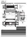
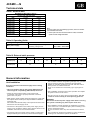
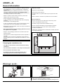
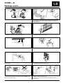
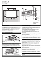
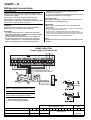
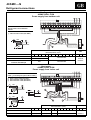
40SMC---N
INSTALLATION MANUAL
IR Remote Control
“Room Controller”
“Zone Manager”
The unit can be used with infrared Remote Control, with the Carrier “Room
Controller” or “Zone Manager”.
For the installation instructions of the wired remote controls and the remote control refer
to the corresponding manuals.
For the instructions for use of the air conditioner and outdoor installation instructions
refer to the corresponding manuals.
Contents
Dimensions .................................................................................................
Technical data .............................................................................................
General information ....................................................................................
Warnings: avoid... .......................................................................................
Installation...................................................................................................
Refrigerant connections..............................................................................
Electric connection .....................................................................................
Alarm code ..................................................................................................
Accessories .................................................................................................
Guide for the owner .....................................................................................
Fan diagrams ..............................................................................................
Cooling only and
heat pump
models
40SMC009N
40SMC012N
40SMC018N
40SMC024N
40SMC028N
40SMC036N
40SMC048N
40SMC060N
Page
2
3
3/4
4/5
6
7
8/12
12
12
12
13/14
ENGLISH
40SMC---N
Ducted above-ceiling units (Cooling only and heat pump)
Power
supply
230V~50Hz
GB - 1
40SMC---N
Dimensions
Ø AP
Ø AN
햵
햹
햻
햲
햳
햴
햵
햶
햷
햸
햹
햺
햻
Ø AM
K
AC
AE
L
N
M
AF
45
P
햺
AD
Coil
Fan
Drain pan
Drain connection Ø AP
Outside air intake
Electrical box
Unit support
Air filter
Liquid Ø AM
Gas Ø AN
AC
E
D
19
H
AB
29
19
G
260
햳
햷
햸
햲
햴
Y
180
J
B
9
Z
AJ
AK
F
AL
I
AG
AH
햶
햺
Ø AM
햻
32
28
Ø AN
Ø AP
햵
Y
S
T
X
180
C
Z
28
87
U
V
W
Q
V
U
R
Q
A
40SMC---N
Ø AM
Ø AN
Ø AP
009
1/4”
3/8”
20
012 - 018
1/4”
1/2”
20
024
1/4”
1/2”
25
028
1/4”
5/8”
25
036 - 048 - 060
3/8”
3/4”
25
40SMC---N
A
B
C
D
E
F
G
H
I
J
K
L
M
N
P
Q
R
S
009 - 012 - 018
725
555
220
743
781
262
222
71
23
607
31.5
59
140
200
35
33
659
45
024 - 028 - 036
925
660
285
943
981
241.5
321
97.5
23
712
33.5
118.5
199.5
264.5
35
37.5
850
87.5
048 - 060
1250
750
310
1268
1306
261
321
168
22
801
43
143
224
289
43
110
1030
103
AL
40SMC---N
T
U
V
W
X
Y
Z
AB
AC
AD
AE
AF
AG
AH
AJ
AK
009 - 012 - 018
143
62
211
179
103
13
27
3,5
89
545
33
142
31
90
128
54
38
90
276
193
125
23
82
31
99
725
33
207
31
110
160
50
75
203
290
264
116
23
107
31
109
1030
32
233
32
140
185
50
75
024 - 028 - 036 165.5
048 - 060
175
When designin an installation ensure the use of up-to-date drawings available from your local Carrier office.
GB - 2
40SMC---N
Technical data
ENGLISH
Table I: Nominal data
MAXIMUM POWER INPUT (WATT) (1)
Cooling only and heat pump
Unit
Cooling
Heating
40SMC009N
120
120
40SMC012N
130
130
40SMC018N
180
180
40SMC024N
290
290
40SMC028N
320
320
40SMC036N
420
420
40SMC048N
576
576
40SMC060N
620
620
Note:
For power supply wire size and delay type fuses, refer to the outdoor
unit installation instructions.
(1)
Power inputs have been measured with free outlet, at maximum
speed and with voltage 264V~50Hz.
Table II: Operating limits
Cooling / Heating
Refer to outdoor unit installation manual.
Nominal single-phase voltage
230V ~ 50Hz
Operating voltage limits
min. 198V – max. 264V
Main power supply
Table III: External static pressure
40SMC---N
Nominal static
pressure (Pa)
Maximum static
pressure (Pa)
009
012
018
024
028
036
048
060
33
40
45
60
50
50
70
80
60
70
160
General information
Unit installation
Read this instruction manual thoroughly before starting
installation.
• This unit complies with the low-voltage (EEC/73/23) and
electromagnetic compatibility (EEC/ 89/336) directives.
• Follow all current national safety code requirements.
In particular ensure that a properly sized and connected
ground wire is in place.
• Make sure the electric system voltage and frequency comply with
the required values and the power input available is suitable for
running the unit.
Also ensure that national safety code requirements have been
followed for the main supply circuit.
• Connection of the system to the mains power supply is to be
carried out in compliance with the wiring diagram shown in the
installation instructions of the external section.
• Connect the indoor and outdoor units by means of copper pipes
equipped with flanged connections (not included in the supply).
Use insulated seamless refrigeration grade pipe only, (Cu DHP
type according to ISO1337), degreased and deoxidized,
suitable for operating pressures of at least 4200 kPa and for
burst pressure of at least 20700 kPa.
Under no circumstances must sanitary type copper pipe be
used.
• After installation thoroughly test system operation and explain
all system functions to the owner.
• Use this unit only for factory approved applications: the unit
cannot be used in laundry or steam pressing premises.
WARNING:
Disconnect the mains power supply switch before servicing
the system or handling any internal parts of the unit.
• This installation manual describes the installation procedures
of the indoor unit of a residential split system consisting of two
Carrier manufactured units.
Do not connect this unit to any other manufacturer's outdoor
unit.
The manufacturer declines any liability for system malfunction
resulting from unauthorised system combinations.
GB - 3
40SMC---N
General information
• The manufacturer declines any liability for damage resulting
from modifications or errors in the electrical or refrigerant
connections.
Failure to observe the installation instructions, or use of the
unit under conditions other than those indicated in table
“Operating limits” of the outdoor unit installation manual, will
immediately invalidate the unit warranty.
• Failure to observe electric safety codes may cause a fire
hazard in the event of short circuits.
Positions to avoid:
• Exposure to direct sunlight.
• Areas close to heat sources.
• On damp walls or in positions that may be exposed to water
hazard.
• Where curtains or furniture may obstruct free air circulation.
• Inspect equipment for damage during transport.
In case of damage file an immediate claim with the shipping
company.
Do not install or use damaged units.
Recommendations:
• In case of malfunction turn the unit off, disconnect the mains
power supply and contact a qualified service engineer.
• Consider using an area where installation is easy.
• Choose an area free from obstructions which may cause
uneven air distribution and/or return.
• Choose a position that allows for the clearances required.
• Maintenance of the refrigerant circuit must only be carried out
by qualified personnel.
• All of the manufacturing and packaging materials used for
this appliance are recyclable.
• Look for a position in the room which ensures the best
possible air distribution.
• Install unit in a position where condensate can easily be piped
to an appropriate drain.
• Dispose of the packaging material in accordance with local
requiremements.
• This equipment contains refrigerant that must be disposed of
correctly.
At the end of the unit’s life, the refrigerant must be taken to
special collection points or delivered to the retailer for correct
disposal.
Choosing the installation site
250 mm
200
220
• The unit must be installed in a not easily accessible place.
400
• The SMC---N unit has been conceived for above-ceiling
installation.
• Do not install the unit below 2.5 mm.
• To install the unit at 2.2-2.5 m from the floor, use a
discharge pipe with a minimum length of 250 mm.
Warnings: avoid...
... any obstruction of the unit air intake or supply grilles.
GB - 4
... exposure to direct sunshine, when the unit is operating in the
cooling mode; always use shutters or shades.
... positions too close to heating sources which may damage the unit.
40SMC---N
Warnings: avoid...
ENGLISH
... connecting condensate piping to sewage system drain without
appropriate trap. Trap height must be calculated according to the
unit discharge head in order to allow sufficient and continuous
water evacuation.
... exposure to oil vapours.
... installation in areas with high frequency waves.
... only partial insulation of the piping.
... inclined installation which could cause dripping.
... flattening or kinking the refrigerant pipes or condensate pipes.
5
... horizontal sections or curves of condensate drain piping with less
than 5% slope.
... excessive height difference between outdoor and indoor units
(see installation manual of outdoor unit).
... slack on electrical connections.
... disconnecting refrigerant connections after installation: this
will cause refrigerant leaks.
... unnecessary turns and bends in connection pipes (see
installation manual of outdoor unit).
Excessive connection pipe length (see installation manual of
outdoor unit).
GB - 5
40SMC---N
Installation
Service area
250 mm
햲
200
220
햳
400
햴
햵
햲
햳
햴
햵
Screws-in rod
Shoch absorbers
Washer
Nut
Unit installation
Condensate drainage
Insert 4 M8 threaded rods into the celling. Introduce the other end
of the rods through the slots of unit suspension brackets.
Position the shock absorbers, add washers and screw the nuts
down until the unit is correctly suported.
If there is sufficient space, a rubber or neoprene sheet can be
placed between the ceiling and the unit.
All units are provided with an internal condensate drain pan which
incorporates a drainage tube 20 mm external Ø (009, 012, 018)
and 25 mm (024, 028, 036, 048, 060).
A tube for evacuating condensates must therefore be provided.
The recommendations below must be followed in all cases:
• Use galvanizad steel, copper or plastic piping.
Do not used ordinary garden hose.
• Use a material that guarantees perfect watertightness on the
drainage pipe.
• If rigid material has been used for the drainage, it is necessary to
provide some kind of elastic coupling in the drainage line to
absorb possible vibrations.
• The drainage line should always be below the connextion itself,
and should also slope to facilitate drainage.
IMPORTANT:
The unit must be perfectly levelled.
햴
WARNING:
No drillholes should be made in the base of the unit, since the
drain pans may be perforated.
햲
햲
햳
햴
햵
Unit
False ceiling
Ceiling
Register cover
햵
햳
Once these operations have been completed, an above-ceiling
installation will be necessary to conceal the unit; do not forget to
install a removable panel to allow for maintenance operations.
Grills of an adequate size should be incorporated in the unit for
return air suction.
쐃
햲 Minimum 5% slope
GB - 6
Ductwork
The ductwork dimensions should be determined in accordance
with the air flow circulating through it and with the available static
pressure of the unit.
These information are available in the final pages of the manual.
Various suggestions are made herebelow, regarding the layout
and design of the said doctwork:
• Whatever type of duct is used, it should not be made of materials
which are flammable, or which give off toxic gases in the event
of a fire.
The internal surfaces should be smooth, and not conteminate the
air which passes through.
• At the points where the duct joins with the unit, it is advisable to
use a flexible connection which absorbs vibration and prevents
the transmission of noise inside the ductwork.
• Bends should be avoided as much as possible near the unit
outlet.
If unavoidable, they should be as slight as possible, and internal
deflectors should be used when the duct is of large dimensiones.
IMPORTANT:
Duct calculation and design must be effected by a qualified
technician.
40SMC---N
Refrigerant connections
ENGLISH
Refer to the outdoor unit installation manual for tube sizing,
and limitations (slope, length, number of bends allowed,
refrigerant charge, etc.).
Tubing diameter
Model
Gas
Liquid
(Suction)
(Discharge)
mm
(inches)
mm
(inches)
9,52
(3/8")
6,35
(1/4")
40SMC 012N-018N-024N
12,70
(1/2")
6,35
(1/4")
40SMC 028N
15,87
(5/8")
6,35
(1/4")
40SMC 036N-048N-060N
19,05
(3/4")
9,52
(3/8")
40SMC 009N
For refrigerant tubes use seamless, insulated refrigeration grade
tube, (Cu DHP type according to ISO1337), degreased and
deoxidized, suitable for operating pressures of at least 4200 kPa
and for burst pressure of at least 20700 kPa.
Under no circumstances must sanitary type copper pipe be used.
Lubricate the tube end and thread of the flare fitting with antifreeze oil.
Finger-tighten the fitting several turns, then tighten it fully with
two wrenches by applying the tightening torque indicated in the
table.
Connection to the unit
Flaring the end of the tubing
Insufficient tightening torque will cause gas leaks.
Overtightening the fittings will damage the tube flaring and
cause gas leaks.
햲
햴
Remove protective caps from the copper tube ends.
Position tube end downward, cut the tube to the required length
and remove the burrs with a reamer.
햳
햲 Adjustable wrench or torque wrench
햳 Outdoor end
햴 Indoor end
Tubing diameter
mm (inches)
Torque
Nm
6,35
(1/4")
18
9,52
(3/8")
42
12,70
(1/2")
55
15,87
(5/8")
65
19,05
(3/4")
100
햵
햶
L
L
Remove flare nuts from the unit connections and place them on
the tube end.
Flare the tube with the flaring tool.
Flare end must not have any burrs or imperfections.
The length of the flared walls must be uniform.
햵 Tube
햶 Tube insulation
햷 Fastening tape
햷
Once all connections have been completed, check for leaks by
using a leak detector specific for HFC refrigerants.
Finally wrap connections with anti-condensate insulation and
tighten with tape, without exerting great pressure on the
insulation.
Repair and cover any possible cracks in the insulation.
Connection pipes and electric cables between indoor and
outdoor units must be fixed to the wall with appropriate
conduits.
GB - 7
40SMC---N
Refrigerant connections
VERY IMPORTANT:
To prevent electrical shock or equipment damage, make
sure the power supply sectioners are open before electrical
connections are made.
If this action is not taken, personal injury may occur.
First make the refrigerant connections and then the
electrical ones. In the case of disassembly, operations must
be carried out in the opposite sequence.
standards in force affecting the installation of air
conditioning equipment.
• To connect a condensate drainage pump follow the wiring
diagram instructions in the next pages.
VERY IMPORTANT:
The installer should place protection elements in the line
according to the legislation in force.
IMPORTANT:
• Make ground connection prior to any other electrical
connections.
• Make electrical connections between units prior to proceeding
to mains supply unit connection.
• According to the installation instructions, the disconnecting
switches from the mains power supply should have a contact gap
(4 mm) such that total disconnection can be ensured under the
conditions provided for by overvoltage class III.
WARNING:
Operation of unit on improper line voltage constitutes
abuse and is not covered by Carrier warranty.
IMPORTANT:
• The mains supply indoor unit – outdoor unit connecting
cable must be H07 RN-F (60245IEC66) type synthetic rubber
insulation with neoprene coating.
Consult the wiring diagram sent with the outdoor unit.
• To effect the unit power supply (wire inlet, conductor
section, protections, etc..), consult the Electrical Data
Table, the wiring diagram sent with the unit and the
NOTE:
• All field electrical connection are the responsibility of the
installer.
Cooling only
40SMC 009N, 012N
Power supply from indoor unit
C
G
P
1
L N N Y O W2 V1 V2 V3 V4 40 41
1 2 3
1
2
10
C
G
P
3
100
1
10 80
IMPORTANT:
Cable 햲 must always be placed above cable 햴.
10
100
3
NOTE:
See the outdoor unit installation manual.
햲 Power supply cable (H07 RN-F)
햴 Interconnection cable (H07 RN-F)
10 80
Indoor and outdoor units
interconnections (mm2)
Model
GB - 8
GND
L
N
GND
N
40SMC009N
3G1,5
3G1,5
40SMC012N
3G2,5
3G2,5
Y
O
W2
V1
V2
V3
CRC
V4
Disconnected
40
41
1
2
3 x 0,75
H03VV-F
3
40SMC---N
Refrigerant connections
ENGLISH
Cooling only
40SMC 009N, 012N
Power supply from outdoor unit
C
G
P
1
L N N Y O W2 V1 V2 V3 V4 40 41
1 2 3
NOTE:
See the outdoor unit installation
manual.
햴 Interconnection cable (H07 RN-F)
10
100
3
3
10 80
Indoor and outdoor units
interconnections (mm2)
Model
GND
L
N
40SMC009N
4G1,5
40SMC012N
4G2,5
40SMC009N, 40SMC012N
combined with Multisplit
4G1
-
Y
O
W2
2
C
G
P
V1
CRC
V2
V3
V4
40
41
1
Disconnected
2
3
3 x 0,75
H03VV-F
Disconnected
Heat pump
40SMC 009N, 012N
Power supply from indoor unit
C
IMPORTANT:
Cable 햲 must always be placed above cable 햴.
햲 Power supply cable (H07 RN-F)
햳 Interconnection cable (H07 RN-F)
햴 Interconnection cable (H07 RN-F)
10
100
G
P
1
L N N Y O W2 V1 V2 V3 V4 40 41
1 2 3
1
1
10 80
10
2
10 80
100
3
3
10 80
C
G
P
2
Indoor and outdoor units
interconnections (mm2)
Model
GND
L
N
GND
N
Y
O
W2
V1
V2
V3
2
CRC
V4
40
41
1
2
3
40SMC009N
3G1,5
3G1,5
2 x 1,5
Disconnected
3 x 0,75
40SMC012N
3G2,5
3G2,5
2 x 1,5
Disconnected
H03VV-F
GB - 9
40SMC---N
Refrigerant connections
Heat pump combined with Multisplit
40SMC 009N, 012N, 018N, 024N
Power supply from outdoor unit
C
G
P
1
L N N Y O W2 V1 V2 V3 V4 40 41
1 2 3
햲 Interconnection cable (H07 RN-F)
햳 Interconnection cable (H07 RN-F)
1
10 80
2
10 80
1
C
G
P
2
Indoor and outdoor units
interconnections (mm2)
Model
GND
40SMC 009,012,018,024N combined with Multisplit
L
N
Y
3G1
O
W2
V1
3x1
V2
V3
2
CRC
V4
40
41
1
Disconnected
2
3
3 x 0,75
H03VV-F
Cooling only
40SMC 018N, 024N, 028N, 036N, 048N, 060N
C
G
P
1
NOTE:
See the outdoor unit installation manual.
R C C Y O W2 S V1 V2 V3 V4 40 41
1 2 3
햴 Interconnection cable (H07 RN-F)
10
100
3
10 80
C
G
P
3
Indoor and outdoor units
interconnections (mm2)
Model
40SMC018, 024, 028N
40SMC036, 048, 060N
GB - 10
GND
R
C
4G1
Y
O
W2
S
V1
2
CRC
V2
V3
Disconnected
V4
40
41
1
2
3 x 0,75
H03VV-F
3
40SMC---N
Refrigerant connections
ENGLISH
Heat pump
40SMC 018N, 024N, 028N, 036N, 048N, 060N
1
NOTE:
See the outdoor unit installation manual.
R C C Y O W2 S V1 V2 V3 V4 40 41
햳 Interconnection cable (H07 RN-F)
햴 Interconnection cable (H07 RN-F)
10 80
10
100
C
P
1 2 3
3
2
2
10 80
C
G
P
3
Indoor and outdoor units
interconnections (mm2)
Model
GND
R
40SMC018N, 024N, 028N
C
Y
O
3G1
W2
S
V1
V2
4x1
2
CRC
V3
V4
40
Disconnected
40SMC036N, 048N, 060N
41
1
2
3
3 x 0,75
H03VV-F
Legend
1 Indoor unit
L
N
R
C
G
Y
Compressor interlocking
contac
O Reversing valve control
(Heat pump only)
W2 Outdoor fan signal
S Thermostat end of defrosting
signal
Earth
Live power supply
Neutral power supply
Power supply connection to outdoor unit
Neutral, connection to outdoor unit
V1, V2, V3, V4
40, 41
1, 2, 3
Indoor fan speed
Electric heater control
Room Controller control
2 Room Controller (CRC)
P
G
C
Power supply
Earth
Signal
Electric connections for auxiliary pump installation - 40SMC009N-40SMC012N
1
1
1
J5
J10
J3
1
J2
J13
1
J6A
1
J17
1
T1
K1
J6B
1
J18
J15
J11
J8
1
J7
J4
1
1
J20
1
1
PUMP SENSOR
230Vac - 3,15 A min
N/C
N/O
COM
L N N Y O W2
L
PS
N
230V-1N-50Hz
To make electric connections you need to modify the cables connecting the N or C pole of the terminal block to the J3 pole of the card and
insert the pump contact according to the instructions shown in the diagram above.
GB - 11
40SMC---N
Electric connection
Electric connections for auxiliary pump installation
40SMC018N-40SMC024N- 40SMC028N- 40SMC036N- 40SMC048N- 40SMC060N
J1
1
1
1
J5
J10
J3
1
J2
J13
1
J6A
1
J17
1
J6B
1
J18
J15
J7
J11
1
J8
J4
1
J20
1
1
1
PUMP SENSOR
/
/
To make electric connections you need to modify the cables connecting the N or C pole of the terminal block to the J3 pole of the card and insert
the pump contact according to the instructions shown in the diagram above.
Alarm code, accessories and guide for the owner
Alarm code
Accessories
A diagnostic system is contained in the electronic card to
“check” the system integrity.
When the diagnostic system is under alarm, the red LED
installed onto the main card flashes as indicated below:
• 0,5 sec ON and 0,5 sec OFF with a 5 second pause before the
error code is repeated.
• The number of flashes depends on the error that has been
detected.
For accessories refer to the product catalogues and documents.
Not all of the errors can be reset (see table below).
Error
code
3
4
5
7
10
11
12
*
Error
Air temperature sensor
Internal battery temp. sensor
External battery temp. sensor
Outdoor unit error
EEPROM faulty
Card serial number faulty
Address/zone number incomplete
Resettable
*
YES
YES
YES
YES
YES
YES
YES
NO: Turn off power supply to the system, check and repair, if necessary.
Turn on power.
YES: Check
GB - 12
Guide for the owner
When installation and tests are completed explain the Operation
and Maintenance Manual to the owner, with particular attention to
the main operating modes of the air conditioner, such as:
• Turning the unit on and off.
• Functions of the remote control.
Leave the two installation manuals for the indoor and outdoor
units with the owner for future use during maintenance operations
or for any other needs.
40SMC---N
Fan diagrams
ENGLISH
40SMC012N
40SMC009N
100
100
90
90
80
80
70
70
60
60
1
Pa
Pa
50
50
1
2
40
40
2
3
30
3
30
4
20
20
10
10
0
4
0
70
90
110
130
햶
150
170 180 190
100
120
140
160
180
200
햶
220
40SMC024N
40SMC018N
100
100
90
90
80
80
70
70
60
60
Pa
Pa
1
50
1
50
2
2
40
40
3
30
3
30
4
20
20
10
10
0
4
0
120
150
햶
200
240
170
200
250
300
햶
350
400 410
1 - Super high speed
(optional)
2 - High speed
3 - Medium speed
4 - Low speed
햶 Air flow (l/s)
GB - 13
40SMC---N
Fan diagrams
40SMC028N
40SMC036N
100
100
90
90
80
80
70
70
1
60
1
60
Pa
Pa
2
50
3
40
2
50
40
30
3
30
4
20
20
10
10
0
0
220
250
300
햶
350
400
450
4
300
350
400
200
200
190
190
180
180
170
170
160
160
150
150
140
140
130
130
120
120
110
Pa 100
100
2
3
3
70
50
50
40
40
30
30
20
20
10
10
0
0
400
500
4
60
4
300
600
햶
GB - 14
2
80
60
550
90
80
70
500
1
110
1
90
450
40SMC060N
40SMC048N
Pa
햶
700
800 850 900
1 - Super high speed
(optional)
2 - High speed
3 - Medium speed
4 - Low speed
햶 Air flow (l/s)
300
400
500
600
700
햶
800
900
L010127H27 - 1205
Via R. Sanzio, 9 - 20058 Villasanta (MI) Italy - Tel. 039/3636.1
The manufacturer reserves the right to change any product specifications without notice.
December, 2005.
Printed in Italy